International Journal of Scientific Engineering and Research (IJSER) www.ijser.in
ISSN (Online): 2347-3878, Impact Factor (2015): 3.791
Volume 4 Issue 7, July 2016 Licensed Under Creative Commons Attribution CC BY
Analytical Study of FRCM under Elevated
Temperature
Raichel Biju George1, Shobha Elizabeth Thomas
2
1PG Scholar, Structural Engineering, Sree Buddha College of Engg., Pattoor, Alappuzha, Kerala, India
2Asst. Professor, Dept of Civil Engineering, Sree Buddha College of Engg., Pattoor, Alappuzha, Kerala, India
Abstract: The term strengthening means to increase the capacity of an existing structure and probability that it will survive for a long-
period of time. This can be accomplished through strengthening by externally bonded FRP. Externally bonded FRP have advantages
like light-weight, high tensile strength and resistance to corrosion which makes it an alternative to conventional methods. But it has
certain limitations like poor behaviour of epoxy resin at temperatures above the glass transition temperature and relative high cost of
epoxies [1]. The epoxy resin can be substituted with a cementitious matrix to improve the overall performance of strengthening system.
This new system is known as Fiber Reinforced Cementitious Matrix (FRCM). FRCM has long-term durability, inherent heat resistance
and compatibility with the substrate. In this paper, the mechanical properties of beam strengthened with FRCM at elevated temperature
are studied analytically using ANSYS software. The reduction in load carrying capacity of FRCM strengthened beam at 300ºC after
1.5hrs, 2hrs, 3hrs and 6hrs were 2.1%, 2.8%, 5.6% and 12.5% respectively.
Keywords: Strengthening, FRP, FRCM, Elevated temperature
1. Introduction
Repairing of a structure means to return the strength of the
building or part of building. A building may get damaged
through many ways like corrosion, overloading or by
exposure to severe weather. If these damages are not repaired
properly, the building may fail to continue its function.
Externally bonded reinforcement is a good option as
retrofitting system. Example for externally bonded
reinforcement is fiber reinforced polymer (FRP). FRP
consists of a polymer matrix and fibers (e.g. carbon, glass
fibers). The advantages of FRP are light weight, high tensile
strength and corrosion resistant. But it has several
disadvantages due to the epoxy resin like debonding of FRP
from the concrete structure, unstable nature of the epoxy at
higher temperatures, and expensive.
A new composite material called fiber reinforced
cementitious matrix (FRCM) can be used as an alternative to
FRP. FRCM consists of a fiber mesh (e.g. carbon, PBO) and
a cementitious matrix. The epoxy resin in the FRP is replaced
by a cement mortar in FRCM, thus reducing the drawbacks
offered by epoxy. FRCM has the following advantages [2].
(i) Compatibility with concrete
(ii) Corrosion resistant and long term durability
(iii) Inherent heat resistance
The application of FRCM for strengthening and change in
the properties at higher temperatures should be further
studied.
Bisby L.A experimented on FRCM systems for flexural
strengthening on concrete under high temperature exposure.
The type of FRCM used for the study was polybenzoxozole
(PBO) FRCM and the experimental program included twelve
RC beams – four were strengthened with FRP, six were
strengthened with PBO FRCM and remaining two control
beams. The beams were tested up to temperature of 120ºC
and proved to be effective in bending [3]. As an extension
they conducted an experiment on FRP versus FRCM at
temperatures 50ºC and 80ºC i.e. glass transition temperature
of epoxy resin. Beams were strengthened with CFRP and
PBO FRCM. The reduction of strength in FRP strengthened
beam was from 52% to 74% compared with 6% to 28%
reduction in FRCM strengthened beam [4].
Rizwan Azam et al. investigated the effectiveness of different
types of FRCM systems to strengthen shear critical
reinforced concrete beams [5]. The results showed increase
of load carrying capacity ranged from 19% to 105%. U-
wrapped and side bonded strengthening schemes were also
adopted and both exhibited similar behaviour.
2. Objectives
1. To investigate flexural behavior of FRCM strengthened
beam using ANSYS software
2. To investigate the mechanical properties of FRCM beam at
elevated temperatures.
3. Beam Specimen
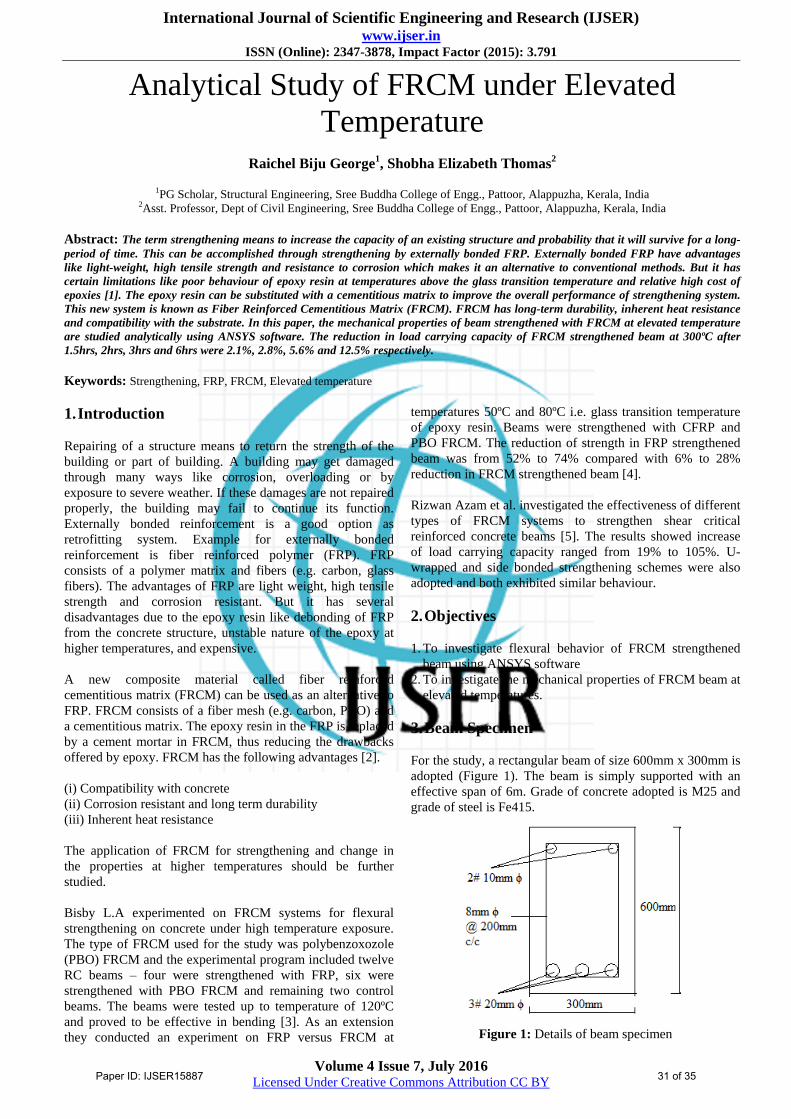
For the study, a rectangular beam of size 600mm x 300mm is
adopted (Figure 1). The beam is simply supported with an
effective span of 6m. Grade of concrete adopted is M25 and
grade of steel is Fe415.
Figure 1: Details of beam specimen
Paper ID: IJSER15887 31 of 35

International Journal of Scientific Engineering and Research (IJSER) www.ijser.in
ISSN (Online): 2347-3878, Impact Factor (2015): 3.791
Volume 4 Issue 7, July 2016 Licensed Under Creative Commons Attribution CC BY
The fiber for FRP is carbon. FRP is provided as three layers
each of 1mm. The material for fiber mesh in FRCM is
polybenzoxozole (PBO) and two layers of cement mortar
(2mm each) is used Table 1 shows the properties of carbon
FRP and FRCM.
Table 1: Material properties
Material
Modulus of
Elasticity
(GPa)
Poisson’s
ratio
Concrete 25 0.2
Steel 200 0.3
FRCM
PBO 270 0.33
Cement
Mortar 6 0.2
FRP
Ex = 62
Ey = 4.8
Ez = 4.8
vxy = 0.22
vxz = 0.22
vyz = 0.3
4. Finite Element Analysis
4.1 Elements used
Solid65 was used for concrete beam. It has 8 nodes with 3
degree of freedom at each nodes, translations in nodal, x, y &
z directions. Beam188 was used for steel reinforcement. It is
a 2-node linear beam element in 3-D with six degrees of
freedom at each node. For FRP, solid185 layered element
was used, which has eight nodes having three degree of
freedom. In the case of FRCM, for PBO fiber Link180 3D
spar and for cement mortar SOLID185 with layered solid
option is adopted. For the support and loading plate,
SOLID185 was used.
4.2 Real Constants and Beam Section
Real constant for concrete is defined as 1. Real constant for
PBO fiber is defined as 2 and its area of cross-section given
is 3 mm2. Shell section is defined for FRP and cementitious
mortar and it includes thickness of layer and its orientation
with respect to the axis. The beam section is defined for the
steel reinforcement. The radius of the bar is given and shape
of section is given as circular.
4.3 Material Properties
Linear properties such as modulus of elasticity and Poisson’s
ratio and non-linear properties like stress-strain curve, yield
stress of steel reinforcement etc. are added.
4.5 Modelling and meshing
One-fourth of Concrete beam of size 600x300x6800 mm was
modelled by creating volumes. Meshing was done by giving
each specified element edge length size. Steel reinforcement
is created by joining each nodes formed by meshing by
specifying the section number, thus separate meshing is not
required for steel reinforcement. After meshing, the areas
between the supporting and loading plates, FRP layer,
cementitious layer and beam should be bonded properly by
contact pair.
Figure 2: One-fourth beam model
4.5 Analysis
The beam is subjected to four-point bending. The appropriate
boundary and support conditions were applied. Static
structural analysis is done. Each load step is defined and
during the analysis load step is divided into substeps. The
time at end load step in solution and control option is total
load at the load step. The load step file is solved.
Figure 3: Beam model with support and boundary conditions
4.6 Results
The ultimate load for control beam obtained from static
analysis is 86.5 kN. The maximum loads obtained for FRP
and FRCM strengthened beams are shown in Table 2. The
nodal displacement contours and the load versus deflection
graph for control beam, FRP and FRCM strengthened beams
are shown in Figure 4 to Figure 9.
Table 2: Ultimate loads obtained
Specimen Ultimate load
obtained (kN) Deflection (mm)
Control beam 86.5 4.42
FRP strengthened
beam 99.7 5.73
FRCM strengthened
beam 107.6 6.13
Paper ID: IJSER15887 32 of 35

International Journal of Scientific Engineering and Research (IJSER) www.ijser.in
ISSN (Online): 2347-3878, Impact Factor (2015): 3.791
Volume 4 Issue 7, July 2016 Licensed Under Creative Commons Attribution CC BY
Figure 4: Deflection of control beam
Load vs Deflection
86.5
0
10
20
30
40
50
60
70
80
90
100
0 1 2 3 4 5
Deflection (mm)
Lo
ad
(k
N)
Control
beam
Figure 5: Load vs. Deflection at mid-span of control beam
Figure 6: Deflection of FRP strengthened beam
Load vs Deflection
99.7
0
10
20
30
40
50
60
70
80
90
100
110
0 1 2 3 4 5 6 7
Deflection (mm)
Load
(k
N)
FRP strengthened
beam
Figure 7: Load vs. Deflection of FRP strengthened beam
Figure 8: Deflection of FRCM strengthened beam
Load vs Deflection
107.6
0
10
20
30
40
50
60
70
80
90
100
110
120
0 1 2 3 4 5 6 7Deflection (mm)
Lo
ad
(k
N)
FRCM strengthened
beam
Figure 9: Load vs Deflection of FRCM strengthened beam
5. Coupled Thermal and Structural Analysis
5.1 Preprocessor
The element used for PBO fiber is LINK33 and rest is
SOLID70. Thermal conductivity, specific heat and Thermal
expansion coefficient are defined as the thermal properties.
The beam is modeled. The thermal load is applied on the
beam on the areas of the volume. The duration of heating is
defined as time at the end of load step for the thermal
analysis.
Along with thermal analysis, structural analysis is also done
in order to know the flexural behaviour of the strengthened
beam at higher temperature. After the analysis the results
were plotted. The combined thermal and structural analysis
was done at 300ºC up to duration of 6hrs. The thermal
properties of the materials used are given Table 3.
Table 3: Thermal properties
Materials Density
(kg/m3)
Specific heat
(J/kgºC)
Thermal
Conductivity
(W/mºC)
Concrete 2400 1000 1.2
Steel 7875 500 60
FRCM- PBO
fiber 1560 1600 20
FRCM – cement
mortar 1800 900 0.72
5.2 Results
The ultimate loads obtained for FRCM strengthened beam
after 1.5hrs, 2hrs 3hrs and 6hrs at 300ºC are 105.4kN, 104.6
kN, 101.55 kN and 94.12 kN respectively which is higher
than the maximum load carrying capacity of control beam.
Their corresponding deflections are 6.29mm, 6.4mm,
Paper ID: IJSER15887 33 of 35
International Journal of Scientific Engineering and Research (IJSER) www.ijser.in
ISSN (Online): 2347-3878, Impact Factor (2015): 3.791
Volume 4 Issue 7, July 2016 Licensed Under Creative Commons Attribution CC BY
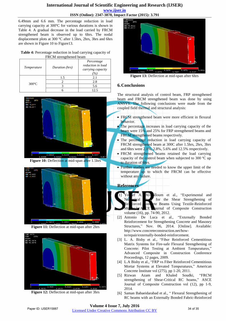
6.49mm and 6.6 mm. The percentage reduction in load
carrying capacity at 300ºC for various durations is shown in
Table 4. A gradual decrease in the load carried by FRCM
strengthened beam is observed up to 6hrs. The nodal
displacement plots at 300 ºC after 1.5hrs, 2hrs, 3hrs and 6hrs
are shown in Figure 10 to Figure13.
Table 4: Percentage reduction in load carrying capacity of
FRCM strengthened beam
Temperature Duration (hrs)
Percentage
reduction in load
carrying capacity
(%)
300ºC
1.5 2.1
2 2.8
3 5.6
6 12.5
Figure 10: Deflection at mid-span after 1.5hrs
Figure 11: Deflection at mid-span after 2hrs
Figure 12: Deflection at mid-span after 3hrs
Figure 13: Deflection at mid-span after 6hrs
6. Conclusions
The structural analysis of control beam, FRP strengthened
beam and FRCM strengthened beam was done by using
ANSYS. The following conclusions were made from the
coupled field thermal and structural analysis:
FRCM strengthened beam were more efficient in flexural
behavior.
The percentage increases in load carrying capacity of the
beam were 15% and 25% for FRP strengthened beams and
FRCM strengthened beams respectively.
The percentage reduction in load carrying capacity of
FRCM strengthened beam at 300C after 1.5hrs, 2hrs, 3hrs
and 6hrs were 2.1%, 2.8%, 5.6% and 12.5% respectively.
FRCM strengthened beams retained the load carrying
capacity of the control beam when subjected to 300 ºC up
to duration of 6hrs.
Further studies are needed to know the upper limit of the
temperature up to which the FRCM can be effective
without any failure.
References
[1] Yousef A. Al-Salloum et al., “Experimental and
Numerical Study for the Shear Strengthening of
Reinforced Concrete Beams Using Textile-Reinforced
Mortar,” ASCE Journal of Composite Construction
volume (16), pp. 74-90, 2012.
[2] Antonio De Luca et al., “Externally Bonded
Reinforcement for Strengthening Concrete and Masonry
Structures,” Nov. 06, 2014. [Online]. Available:
http://www.concreteconstruction.net/how-
to/repair/externally-bonded-reinforcement.
[3] L. A. Bisby et al., “Fiber Reinforced Cementitious
Matrix Systems for Fire-safe Flexural Strengthening of
Concrete: Pilot Testing at Ambient Temperatures,”
Advanced Composite in Construction Conference
Proceedings, 12 pages, 2009.
[4] L.A Bisby et al., “FRP vs Fiber Reinforced Cementitious
Mortar Systems at Elevated Temperatures,” American
Concrete Institute vol (275), pp 1-20, 2011.
[5] Rizwan Azam and Khaled Soudki, “FRCM
strengthening of Shear-Critical RC beams,” ASCE
Journal of Composite Construction vol (12), pp 1-9,
2014.
[6] Saman Babaeidarabad et al., “ Flexural Strengthening of
RC beams with an Externally Bonded Fabric-Reinforced
Paper ID: IJSER15887 34 of 35

International Journal of Scientific Engineering and Research (IJSER) www.ijser.in
ISSN (Online): 2347-3878, Impact Factor (2015): 3.791
Volume 4 Issue 7, July 2016 Licensed Under Creative Commons Attribution CC BY
Cementitious Matrix,” ASCE Journal of Composite
Construction vol (18), pp 1-12, 2014
Author Profile
Raichel Biju George received B.Tech degree in Civil
Engineering from Sree Buddha College of Engineering,
Pattoor, Kerala and currently pursuing M.Tech degree in
Structural Engineering.
Shobha Elizabeth Thomas is Assistant Professor,
Department of Civil Engineering, Sree Buddha College of
Engineering, Pattoor, Kerala. She received M.Tech degree in
Structural Engineering from SRM University and B.Tech
degree in Civil Engineering from M.G University.
Paper ID: IJSER15887 35 of 35


