
ANNEXURE – 5 LOAD TEST REPORTS

Annexure-5
15t Mobile Crane Page No:
LOAD TEST REPORT OF 15t MOBILE CRANE
1. Equipment Details:
1.1 15t capacity Mobile Crane VALF/MC/15T/01 WORK STATION- A
1.2 Capacity 15t at 3.5m operating radius
1.3 Load Test venue
1.4 Date
2. Pre-Checks of trailer: Check the 15t Capacity Mobile crane as per the daily checklist 3. Procedure for Load Testing:
Description With no load With load Remarks
Power Plant
Power Plant fitted with ALU 412 Ashok Leyland water cooled engine with Spark Arrestor fitted
to engine exhaust. Dash board parameters :
Engine oil pressure (1.0-5.5ksc)
Volt meter (24V)
Fuel gauge
Engine coolant temperature (750-900C)
Transmission shift lever
Swing control lever
Rear steer control switch
Main hoist control lever
Boom lift control lever
Transmission range selector switch
Outrigger selector panel
Outrigger extension / retraction switch
Park brake control switch
360 degree swing lock control
Load moment indicating (LMI) control panel
Differential lock switch

Annexure-5
15t Mobile Crane Page No:
Description With no load With load Remarks
Boom System: Boom system provided with 3 section telescopic full power boom extending from 9.4m to 22.9m. Telescoping is mechanically synchronized with single lever control. Telescopic sections slide on adjustable and replaceable lower friction wear pads. The boom provided with boom angle, boom radius indicator, boom length indicator, max. permissible load indicator, overload warning indicator, limit switch etc.,
Function:
Boom up (-30 to 760)
Boom down (760 to -30)
Boom Telescope extraction (22.9m)
Boom Telescope retraction (9.4m)
Hoist System The Hoist System provided with power up and power lowering , automatic brakes for hoist system, 16mm dia, 137 m long non-rotating rope of suitable capacity , overload warning for hoist system, load indicator etc.,
Function :
Hoist up
Hoist down
Hoist brake
Slew System 360 degree slew system provided with spring applied hydraulically release brake and slew lock.
Function :
Clock wise ( 2 RPM)
Anti-clock wise( 2 RPM)
Slew system brake

Annexure-5
15t Mobile Crane Page No:
Description With no load With load Remarks
Outrigger System: The out rigger system is provided with hydraulic operated independent horizontal and vertical movements. The controls of outriggers provided at operator’s cab, level indicator at operator’s cabin and also provided with failsafe lock for safety.
Function :
Front outriggers
Front left outrigger extraction
Front left outrigger retraction
Front right outrigger extraction
Front right outrigger retraction
Rear outriggers
Rear left outrigger extraction
Rear left outrigger retraction
Rear right outrigger extraction
Rear right outrigger retraction
Transmission:: Transmission is
engine mounted multi speed power shift of 6Forward / 6 Reverse speeds.
Function :
Transmission range selector switch (HI / LOW)
Forward
Reverse
Steering The steering system
provided with 4 main steering modes – front only, rear only, crab and coordinated steering
Function :
Axle differential lock
Four wheel steering
Front wheel steering
Rear wheel steering
Four wheel steering
Crabbing
Brakes The crane provided with foot operated service brake and parking brake which acts as failsafe brake.

Annexure-5
15t Mobile Crane Page No:
Description With no load With load Remarks
Function :
Service brake of the crane
Parking brake of the crane
Hydraulic System: The Hydraulic system is provided with 2 main pumps & steering pumps driven by engine through PTO. The hydraulic system can be operated by precision 4 way double acting pilot operated control valve, permits simultaneous control of multiple crane functions by 2 individual valve banks. The capacity of the hydraulic reservoir is 341lts, oil cooled with temp control, full flow return type filter with by-pass protection, service indicator, oil level indicator for reservoir and replaceable type filter cartridge.
Function :
Condition of hydraulic hoses (leaks etc)
Functioning of hydraulic pumps
Maintenance Details:
Type of maintenance scheduled Monthly, quarterly, Annual
Maintenance last attended
Next maintenance due
Load test results are found Satisfactory. Date: Contractor’s Supervisor Engineer-in-charge

Annexure-5
LOAD TEST REPORT OF VOLVO & HIPPO HAULERS 1. Equipment details:
1.1
HIPPO Hauler – 1 VALF/HA/70t/01
WORK STATION-A
HIPPO Hauler – 2 VALF/HA/70T/02
VOLVO Hauler -1 VALF/HA/70T/03
VOLVO Hauler -2 VALF/HA/70T/04
VOLVO Hauler -3 VALF/HA/70T/05
VOLVO Hauler 520 HP AP 26 Y 7685 WORK STATION-B
VOLVO Hauler 400 HP AP 26 TB 5085
1.2 Capacity 86t GCW
1.3 Load Test Venue
1.4 Date
2. Pre-Checks: Daily Checks for Hauler and Hydraulic suspension Goldhofer trailer / Cometto trailer as per the Daily Checklists shall be carried out. 3. No load performance of Hauler & Trailer:
Sl No Item Status
01 Connect the Hauler and Trailer – adjust the steering wedge play (Tighten fully with hand and loosen 1/4th turn).
02 Start the Hauler engine and pressurize the trailer and hauler lines and ensure release of parking/ fail-safe brakes.
03 Start Hydraulic suspension trailer’s Hydraulic power pack
and adjust the trailer platform level to 1165mm± 10mm at all four corners.
04 Check Wheel alignment of trailer and readjust if required.
05 Check Performance of Hauler and trailer in no load condition.
4. Dead Weight / Tools & Materials Required
Sl No Item Qty Status
1. Concrete block – 55t Dead weight 1 No
2. Four legged Handling slings for the above blocks
1 No
3. Crane facility for loading the block 1 No
4. Felt pieces As required
5. Steel Rule 1 No.
6. 15m tape 1 No.

Annexure-5
5. Procedure for Load testing:
Sl No Item Status
01 Take the hauler and trailer to the facility where the concrete blocks and EOT crane facility are available for loading of concrete blocks.
02 Spread the felt pieces on the trailer to have even seating of the concrete blocks.
03 Load the concrete blocks by using the EOT crane/ mobile crane at a distance of 3.5m from rear end of the trailer as per the Loading Scheme:
04 Check for any abnormality and leaks at hydraulic pipe lines, hoses and couplings in loaded condition
05 Check the performance of the hauler and trailer under loaded condition and record the parameters
6. Performance of the Hauler & Trailer
Sl No
Description Observations
No load With load
1. Engine: Eng Oil Pressure - Idling (between 1.0 and 3.0 bar) Eng Oil Pressure at Operating speed (between 3.0 and 5.5 bar) Radiator coolant Temp Maximum (Indicator should be in green zone) Charging System :
Should show charging Deflection of pointer on +ve side
2. Clutch - Engagement & disengagement - For any slip
3. Transmission - Engagement & Disengagement of
gears. - For any slip - For any abnormality
4. Steering (Hauler & Trailer) - Function of steering on both sides. - For any other abnormality
5. Brakes ( Hauler & Trailer) Service Brakes

Annexure-5
Sl No
Description Observations
No load With load
- Function of brakes on all wheels. - Effectiveness of brakes Parking Brakes - Effectiveness of brakes
6. Gradient: - Performance of the Equipment
7. For any leaks in hose connections
8. Function of fifth wheel coupling
7. Maintenance Details: Hauler maintenance Details::
Type of maintenance scheduled Monthly, half yearly & Annual
Maintenance last attended
Next maintenance due
Hydraulic Suspension Trailer::
Type of maintenance scheduled Quarterly & Annual
Maintenance last attended
Next maintenance due
Load test results are found Satisfactory. Date: Contractor’s Supervisor Engineer-in-charge

Annexure-5
Annexure-5
AMW Haulers load test Report
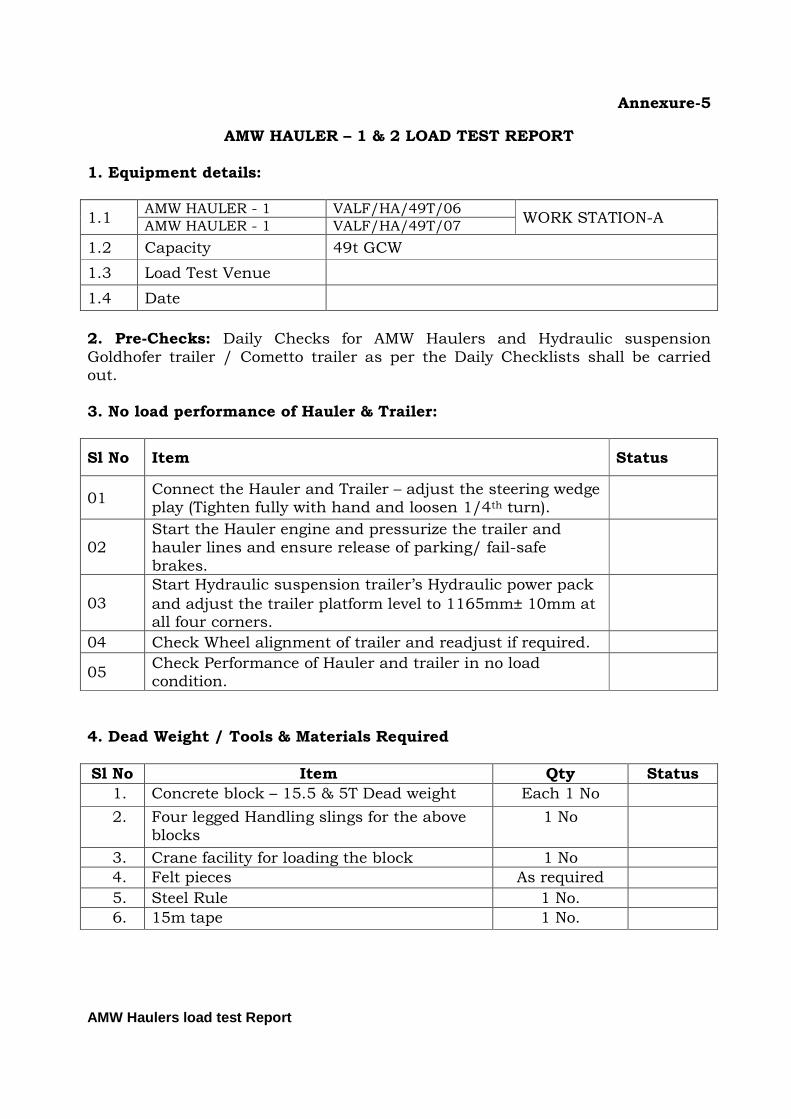
AMW HAULER – 1 & 2 LOAD TEST REPORT 1. Equipment details:
1.1 AMW HAULER - 1 VALF/HA/49T/06
WORK STATION-A AMW HAULER - 1 VALF/HA/49T/07
1.2 Capacity 49t GCW
1.3 Load Test Venue
1.4 Date
2. Pre-Checks: Daily Checks for AMW Haulers and Hydraulic suspension Goldhofer trailer / Cometto trailer as per the Daily Checklists shall be carried out. 3. No load performance of Hauler & Trailer:
Sl No Item Status
01 Connect the Hauler and Trailer – adjust the steering wedge play (Tighten fully with hand and loosen 1/4th turn).
02 Start the Hauler engine and pressurize the trailer and hauler lines and ensure release of parking/ fail-safe brakes.
03
Start Hydraulic suspension trailer’s Hydraulic power pack
and adjust the trailer platform level to 1165mm± 10mm at all four corners.
04 Check Wheel alignment of trailer and readjust if required.
05 Check Performance of Hauler and trailer in no load condition.
4. Dead Weight / Tools & Materials Required
Sl No Item Qty Status
1. Concrete block – 15.5 & 5T Dead weight Each 1 No
2. Four legged Handling slings for the above blocks
1 No
3. Crane facility for loading the block 1 No
4. Felt pieces As required
5. Steel Rule 1 No.
6. 15m tape 1 No.

Annexure-5
AMW Haulers load test Report
5. Procedure for load testing:
Sl No Item Status
01 Take the hauler and trailer to the facility where the concrete blocks and EOT crane facility are available for loading of concrete blocks.
02 Spread the felt pieces on the trailer to have even seating of the concrete blocks.
03 Load the concrete blocks by using the EOT crane/ mobile crane at a distance of 3.5m from rear end of the trailer as per the Loading Scheme: VALF/MHS/T&E/HA/49T
04 Check for any abnormality and leaks at hydraulic pipe lines, hoses and couplings in loaded condition
05 Check the performance of the hauler and trailer under loaded condition and record the parameters
6. Performance of the Hauler & Trailer
Sl No
Description Observations
No load With load
1. Engine:
Eng Oil Pressure - Idling (between 1.0 and 3.0 bar) Eng Oil Pressure at Operating speed (between 3.0 and 5.5 bar) Radiator coolant Temp Maximum (Indicator should be in green zone) Charging System : Should show charging Deflection of pointer on +ve side
2. Clutch
- Engagement & disengagement - For any slip
3. Transmission - Engagement & Disengagement of
gears. - For any slip - For any abnormality
4. Steering (Hauler & Trailer) - Function of steering on both sides. - For any other abnormality
5. Brakes ( Hauler & Trailer) Service Brakes
- Function of brakes on all wheels.

Annexure-5
AMW Haulers load test Report
Sl No
Description Observations
No load With load
- Effectiveness of brakes Parking Brakes
- Effectiveness of brakes
6. Gradient: - Performance of the Equipment
7. For any leaks in hose connections
8. Function of fifth wheel coupling
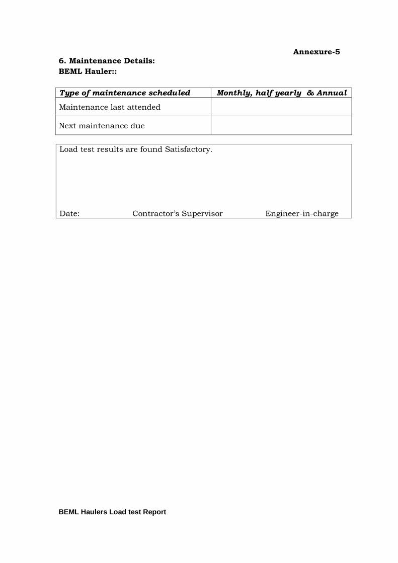
7. Maintenance Details: Hauler maintenance Details::
Type of maintenance scheduled Monthly, half yearly & Annual
Maintenance last attended
Next maintenance due
Hydraulic Suspension Trailer::
Type of maintenance scheduled Quarterly & Annual
Maintenance last attended
Next maintenance due
Load test results are found Satisfactory. Date: Contractor’s Supervisor Engineer-in-charge

Annexure-5
AMW Haulers load test Report

Annexure-5
BEML Haulers Load test Report
BEML HAULR LOAD TEST REPORT
1. Equipment Details:
1.1
70T BEML HAULER - 1 VALF/HA/70T/01 70T BEML HAULER - 2 VALF/HA/70T/01 70T BEML HAULER - 1 SPROB/1745
70T BEML HAULER – 2 PRT/2229
70T BEML HAULER – 3 PRT/7003
1.2 Capacity 86t GCW
1.3 Load Test Venue
1.4 Date
2. Pre-Checks: Daily Checks for BEML Hauler and 30t Flat Bed trailer as per the Daily Checklists shall be carried out.
3. Procedure: The BEML Tractor is load tested for Payload of 30t as per
the procedure given below.
Sl No. Description Status
1 Carry out the pre test checks to the hauler and trailer as per daily check lists.
2 Connect the trailer to the BEML Hauler
3 Take the hauler and trailer for a trial to check the hauler for no load performance.
4 If no load performance is satisfactory, load the trailer with two 30t payload as per the loading scheme: VALF/MHS/T&E/HA/70T.
5 Lash the loads to the trailer platform.
6 Take the hauler and trailer for road trial and check for the parameters given in the performance table 5 and record.
4. Load Details:
Sl No Item Description Qty Remarks
1 30t Flat bed Full Trailer 1 No
2 15t Dead Weights 2 nos
3. 15m Measuring tape 1 No
4. Chalk Pieces 05 nos

Annexure-5
BEML Haulers Load test Report
5. Performance of BEML Haulers:
Sl No Description Observations
No load With load
1. Engine: Lub Oil Pressure - Engine idling (1.0ksc – 2.0 ksc) Lub Oil Pressure – Engine full speed ( 3.0 ksc – 4.0 ksc ) Radiator water temperature Maximum (850C) Charging System : Should show charging By deflection of pointer on +ve side
2. Clutch
- Engagement & disengagement - For any slip
3. Transmission - Engagement & Disengagement
of gears. - For any slip - For any abnormality
4. Rear Axle : For any abnormal sound and over heating of wheel hubs.
5. Wheels : Check rubbing of wheels of wheels against any body surface and wheel shake
6. Steering (Hauler & Trailer) - Function of steering on both
sides. - For any other abnormality
7. Brakes ( Hauler & Trailer) Service Brakes - Function of brakes on all
wheels. - Effectiveness of brakes Parking Brakes - Effectiveness of brakes
8. Gradient:
- Performance of the Equipment
Annexure-5
BEML Haulers Load test Report
6. Maintenance Details:
BEML Hauler::
Type of maintenance scheduled Monthly, half yearly & Annual
Maintenance last attended
Next maintenance due
Load test results are found Satisfactory. Date: Contractor’s Supervisor Engineer-in-charge

Annexure-5
BEML Haulers Load test Report

Annexure-5
Tractor Page No:
LOAD TESTING OF TRACTORS 1. Equipment Details:
1.1 HMT TRACTOR PRT/2031 WORK STATION-B
1.2 Capacity 13t GCW
1.3 Load Test Venue
1.4 Date
2. Materials & Equipment Required for Load Testing:
S.NO Item Qty Status
01 5t Concrete blocks 1 Nos.
02 MST Wheels 2 nos
03 10t Flat bed full trailer 1 No
04 15m Measuring Tape 1 No.
05 Chalk-piece As required
3. Procedure:
Sl No. Description Status
01 Connect the trailer to Eicher tractor
02 Load the trailer with 8t Concrete blocks as per the scheme: SPROB/MHS/T&E/HA/13T
03 Take the Tractor and trailer for road trial and check the performance and record in table 4
4. Performance of Hauler:
Sl No Description Observations
No load With load
1. Engine: Lub Oil Pressure –Engine idling (Should be in Green Zone) Lub Oil Pressure – Engine full speed (Should be in Green Zone ) Temp Maximum (850 Celsius) Charging System : Should show charging By deflection of pointer on +ve side
2. Clutch - Engagement & disengagement - For any slip
3. Transmission - Engagement & Disengagement of
gears. - For any slip - For any abnormality
4. Steering

Annexure-5
Tractor Page No:
Sl No Description Observations
No load With load
- Function of steering on both sides. - For any other abnormality
5. Brakes Service Brakes - Function of brakes on all wheels. - Effectiveness of brakes Parking Brakes - Effectiveness of brakes
6. Gradient: - Performance of the Equipment
5. Maintenance Details:
Type of maintenance scheduled
Monthly, Quarterly, Annual
Maintenance last attended
Next maintenance due
Load test results are found Satisfactory. Date: Contractor’s Supervisor Engineer-in-charge

Annexure-5
Tractor Page No:

Annexure-5
Tractor Page No:
LOAD TESTING OF TRACTORS 1. Equipment Details:
1.1
Eicher Tractor-1 VALF/HA/15T/01 Eicher Tractor-2 VALF/HA/15T/02 Eicher Tractor-3 VALF/HA/15T/03 Eicher Tractor-4 VALF/HA/15T/04 SAME Tractor – 1 AP 26 Y 2900
SAME Tractor – 1 AP 26 Y 2901
SAME Tractor – 1 AP 26 AC 2503
1.2 Capacity 15t GCW
1.3 Load Test Venue
1.4 Date
2. Materials & Equipment Required for Load Testing:
S.NO Item Qty Status
01 5t Concrete blocks 2 Nos.
02 10t Flat bed Full trailer 1 No
04 15m Measuring Tape 1 No.
05 Chalk-piece As required
3. Procedure:
Sl No. Description Status
01 Connect the 10t Flat Bed full trailer to Eicher tractor
02 Load the trailer with 2 Nos. of 5t Concrete blocks as per the scheme: VALF/MHS/T&E/HA/15T
03 Take the Tractor and trailer for road trial and check the performance and record in table 4
4. Performance of Hauler:
Sl No Description Observations
No load With load
1. Engine: Lub Oil Pressure –Engine idling (Should be in Green Zone) Lub Oil Pressure – Engine full speed (Should be in Green Zone ) Temp Maximum (850 Celsius) Charging System : Should show charging By deflection of pointer on +ve side
2. Clutch - Engagement & disengagement - For any slip
3. Transmission

Annexure-5
Tractor Page No:
Sl No Description Observations
No load With load
- Engagement & Disengagement of gears.
- For any slip - For any abnormality
4. Steering - Function of steering on both sides. - For any other abnormality
5. Brakes Service Brakes - Function of brakes on all wheels. - Effectiveness of brakes Parking Brakes - Effectiveness of brakes
6. Gradient: - Performance of the Equipment
5. Maintenance Details:
Type of maintenance scheduled
Monthly, Quarterly, Annual
Maintenance last attended
Next maintenance due
Load test results are found Satisfactory. Date: Contractor’s Supervisor Engineer-in-charge

Annexure-5
Tractor Page No:

Annexure -5
2t Forklift Load test report Page No:
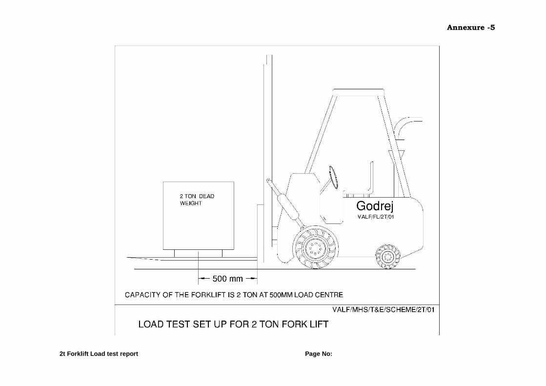
2t CAPACITY FORKLIFT LOAD TEST REPORT
1. Equipment Details:
1.1 2T Godrej Forklift VALF/FL/2T/01 WORK STATION- A
1.2 Capacity 2t at 500mm Load centre
1.3 Load Test venue
1.4 Date
2. Pre-Checks: Daily Checks for 2t forklift as per the Daily Checklists shall be
carried out. 3. Materials Required for Load Testing
Sl No Item Qty Status
1. 2 t cement block 1 no
2. Measuring Tape 15m 1 No
3. Chalk pieces / scriber As required
4. Procedure:
Sl No Description Status
1. Arrange to keep the dummy 2t dummy weight on a level ground.
2. Support the load on forks at 500mm load center as per the Load test scheme no. VALF/MHS/T&E/SCHEME/2T/01
3. Lift the load slowly from the ground and check the fork lift for performance in loaded condition
4. Keep the load in the lift condition for 3 minutes and mark the position of guide way with chalk
5. Slowly bring down the load to the ground in mast back condition.
VI Performance of the Forklift:
Sl No Description Observations
No load With load
01 Engine: Lub Oil Pressure – Engine idling (1.0 ksc - 1.5 ksc) Lub Oil Pressure – Engine full speed (3.0 ksc - 4.0 ksc) Radiator water temperature Maximum (850 Celsius) Charging System :
Should show charging By deflection of pointer on +ve side

Annexure -5
2t Forklift Load test report Page No:
Sl No Description Observations
No load With load
02 Mast Lifting & Lowering: Functioning of Mast lifting and lowering Observe for any leaks in hoses during operations.
03 Mast Tilting:
Functioning of Mast tilting Forward and Backward. Observe for any leaks during operation
04
Transmission - Engagement & Disengagement of
gears. - For any slip - For any abnormality
05 Steering
- Function of steering on both sides. - For any other abnormality
06 Brakes Service Brakes - Function of brakes on all wheels. - Effectiveness of brakes Parking Brakes - Effectiveness of brakes
07 Gradient: - Performance of the Equipment
VII Maintenance Details:
Type of maintenance scheduled Monthly, quarterly, Annual
Maintenance last attended
Next maintenance due
Load test results are found Satisfactory. Date: Contractor’s Supervisor Engineer-in-charge
Annexure -5
2t Forklift Load test report Page No:
Annexure-5
3t Forklift Load test report Page No:
3t CAPACITY FORKLIFT LOAD TEST REPORT 1. Equipment details:
1.1
3T Godrej Forklift – 1 VALF/FL/3T/01
WORK STATION – A 3T Godrej Forklift – 2 VALF/FL/3T/02
3T Godrej Forklift – 3 VALF/FL/3T/03
3T Godrej Forklift PRT/2278 WORK STATION – B
1.2 Capacity 3t at 500mm Load centre
1.3 Load Test venue
1.4 Date
2. Pre-Checks: Daily Checks 3t Forklift as per the Daily Checklists shall be carried out. 3. Materials Required for Load Testing
Sl No Item Qty Status
1. 2t cement block 1 no
2. 1t cement block 1 no
3. Measuring Tape 15m 1 No
4. Chalk pieces / scriber As required
4. Procedure:
Sl No Description Status
1. Arrange to keep the dummy 3t weight on a level ground.
2. Support the load on forks at 500mm load center as per the drawing Scheme. VALF/MHS/T&E/FL/3T
3. Lift the load slowly from the ground and check the fork lift for performance in loaded condition
4. Keep the load in the lift condition for 3 minutes and mark the position of guide way with chalk
5. Slowly bring down the load to the ground in mast back condition.
VI Performance of the Forklift:
Sl No Description Observations
No load With load
01 Engine: Lub Oil Pressure – Engine idling (1.0 ksc - 1.5 ksc) Lub Oil Pressure – Engine full speed (3.0 ksc - 4.0 ksc) Radiator water temperature Maximum (850 Celsius)

Annexure-5
3t Forklift Load test report Page No:
Sl No Description Observations
No load With load
Charging System :
Should show charging By deflection of pointer on +ve side
02 Mast Lifting & Lowering:
Functioning of Mast lifting and lowering Observe for any leaks in hoses during operations.
03 Mast Tilting:
Functioning of Mast tilting Forward and Backward. Observe for any leaks during operation
04
Transmission - Engagement & Disengagement of
gears. - For any slip - For any abnormality
05 Steering - Function of steering on both sides. - For any other abnormality
06 Brakes Service Brakes - Function of brakes on all wheels. - Effectiveness of brakes Parking Brakes - Effectiveness of brakes
07 Gradient: - Performance of the Equipment
VII Maintenance Details:
Type of maintenance scheduled Monthly, quarterly, Annual
Maintenance last attended
Next maintenance due
Load test results are found Satisfactory. Date: Contractor’s Supervisor Engineer-in-charge

Annexure-5
3t Forklift Load test report Page No:

Annexure-5
5t Forklift Load test report Page No:
5t CAPACITY FORKLIFT LOAD TEST REPORT
1. Equipment details:
1.1 5t Godrej Forklift VALF/FL/5T/01 WORK STATION – A
5t Godrej Forklift SPROB/FL/5T/01 WORK STATION – B
1.2 Capacity 5t at 600mm Load Centre
1.3 Load Test Venue
1.4 Date
2. Pre-Checks: Daily Checks for Hauler and Hydraulic suspension Goldhofer trailer / Cometto trailer as per the Daily Checklists shall be carried out. 3. Materials Required for Load Testing
Sl No Item Qty Status
1. 5t Cement Block 1 no
2. Measuring Tape 15m 1 No
3. Chalk pieces / scriber As required
4. Procedure:
Sl No Description Status
1. Arrange to keep the dummy 5t dummy weight on a level ground.
2. Support the load on forks at 600mm load center as per the loading scheme. VALF/MHS/T&E/FL/5T
3. Lift the load slowly from the ground and check the fork lift for performance in loaded condition
4. Keep the load in the lift condition for 3 minutes and mark the position of guide way with chalk
5. Slowly bring down the load to the ground in mast back condition.
5. Performance of the Forklift:
Sl No Description Observations
No load With load
01 Engine: Lub Oil Pressure – Engine idling (1.0ksc - 1.5ksc) Lub Oil Pressure – Engine full speed (3.0ksc-4.0ksc) Radiator water temperature Maximum (850 Celsius) Charging System : Should show charging

Annexure-5
5t Forklift Load test report Page No:
Sl No Description Observations
No load With load
By deflection of pointer on +ve side
02 Mast Lifting & Lowering: Functioning of Mast lifting and lowering Observe for any leaks in hoses during operations.
03 Mast Tilting: Functioning of Mast tilting Forward and Backward. Observe for any leaks during operation
04
Transmission
- Engagement & Disengagement of gears.
- For any slip - For any abnormality
05 Steering
- Function of steering on both sides. - For any other abnormality
06 Brakes Service Brakes
- Function of brakes on all wheels. - Effectiveness of brakes Parking Brakes
- Effectiveness of brakes
07 Gradient: - Performance of the Equipment
6. Maintenance Details:
Type of maintenance scheduled Monthly, quarterly, Annual
Maintenance last attended
Next maintenance due
Load test results are found Satisfactory. Date: Contractor’s Supervisor Engineer-in-charge

Annexure-5
5t Forklift Load test report Page No:

Annexure-5
8t Forklift Load test report Page No:
8t CAPACITY FORKLIFT LOAD TEST REPORT
1. Equipment details:
1.1 8t Godrej Forklift SPROB/FL/8T/01 WORK STATION – B
1.2 Capacity 8t at 600mm Load Centre
1.3 Load Test Venue
1.4 Date
2. Pre-Checks: Daily Checks for 8t Forklift as per the Daily Checklists shall be
carried out. 3. Materials Required for Load Testing
Sl No Item Qty Status
1. 5t Cement Block 1 nos
2. MST wheels 2 nos
3. Measuring Tape 15m 1 No
4. Chalk pieces / scriber As required
4. Procedure:
Sl No Description Status
1. Arrange to keep the dummy 8t dummy weight on a level ground.
2. Support the load on forks at 900mm load center as per the loading scheme. SPROB/MHS/T&E/FL/8T
3. Lift the load slowly from the ground and check the fork lift for performance in loaded condition
4. Keep the load in the lift condition for 3 minutes and mark the position of guide way with chalk
5. Slowly bring down the load to the ground in mast back condition.
5. Performance of the Forklift:
Sl No Description Observations
No load With load
01 Engine:
Lub Oil Pressure – Engine idling (1.0ksc - 1.5ksc) Lub Oil Pressure – Engine full speed (3.0ksc-4.0ksc) Radiator water temperature Maximum (850 Celsius) Charging System :
Should show charging By deflection of pointer on +ve side

Annexure-5
8t Forklift Load test report Page No:
Sl No Description Observations
No load With load
02 Mast Lifting & Lowering:
Functioning of Mast lifting and lowering Observe for any leaks in hoses during operations.
03 Mast Tilting:
Functioning of Mast tilting Forward and Backward. Observe for any leaks during operation
04
Transmission - Engagement & Disengagement of
gears. - For any slip - For any abnormality
05 Steering
- Function of steering on both sides. - For any other abnormality
06 Brakes
Service Brakes
- Function of brakes on all wheels. - Effectiveness of brakes Parking Brakes
- Effectiveness of brakes
07 Gradient:
- Performance of the Equipment
6. Maintenance Details:
Type of maintenance scheduled Monthly, quarterly, Annual
Maintenance last attended
Next maintenance due
Load test results are found Satisfactory. Date: Contractor’s Supervisor Engineer-in-charge

Annexure-5
8t Forklift Load test report Page No:

Annexure-5
10t Forklift Load test report Page No:
10t CAPACITY FORKLIFT LOAD TEST REPORT
1. Equipment details:
1.1 10t Godrej Forklift VALF/FL/10T/01 WORK STATION – A
1.2 Capacity 10t at 900mm Load Centre
1.3 Load Test Venue
1.4 Date
2. Pre-Checks: Daily Checks for Hauler and Hydraulic suspension Goldhofer
trailer / Cometto trailer as per the Daily Checklists shall be carried out. 3. Materials Required for Load Testing
Sl No Item Qty Status
1. 5t Cement Block 2 nos
2. Measuring Tape 15m 1 No
3. Chalk pieces / scriber As required
4. Procedure:
Sl No Description Status
1. Arrange to keep the dummy 10t dummy weight on a level ground.
2. Support the load on forks at 900mm load center as per the scheme. VALF/MHS/T&E/FL/10T
3. Lift the load slowly from the ground and check the fork lift for performance in loaded condition
4. Keep the load in the lift condition for 3 minutes and mark the position of guide way with chalk
5. Slowly bring down the load to the ground in mast back condition.
5. Performance of the Forklift:
Sl No Description Observations
No load With load
01 Engine: Lub Oil Pressure – Engine idling (1.0ksc - 1.5ksc) Lub Oil Pressure – Engine full speed (3.0ksc-4.0ksc) Radiator water temperature Maximum (850 Celsius) Charging System :
Should show charging By deflection of pointer on +ve side

Annexure-5
10t Forklift Load test report Page No:
Sl No Description Observations
No load With load
02 Mast Lifting & Lowering: Functioning of Mast lifting and lowering Observe for any leaks in hoses during operations.
03 Mast Tilting:
Functioning of Mast tilting Forward and Backward. Observe for any leaks during operation
04
Transmission - Engagement & Disengagement of
gears. - For any slip - For any abnormality
05 Steering - Function of steering on both sides. - For any other abnormality
06 Brakes Service Brakes - Function of brakes on all wheels. - Effectiveness of brakes Parking Brakes - Effectiveness of brakes
07 Gradient: - Performance of the Equipment
6. Maintenance Details:
Type of maintenance scheduled Monthly, quarterly, Annual
Maintenance last attended
Next maintenance due
Load test results are found Satisfactory. Date: Contractor’s Supervisor Engineer-in-charge

Annexure-5
10t Forklift Load test report Page No:

Annexure-5
12t Forklift Load test report Page No:
12t CAPACITY FORKLIFT LOAD TEST REPORT
1. Equipment details:
1.1 12t Godrej Forklift PRT/2279
WORK STATION – B 12t Godrej Forklift SPROB/FL/12T/02
1.2 Capacity 12t at 1200mm Load Centre
1.3 Load Test Venue
1.4 Date
2. Pre-Checks: Daily Checks for 8t Forklift as per the Daily Checklists shall be carried out. 3. Materials Required for Load Testing
Sl No Item Qty Status
1. 5t Cement Block 2 nos
2. 2t Dead weight 1 nos
3. Measuring Tape 15m 1 No
4. Chalk pieces / scriber As required
4. Procedure:
Sl No Description Status
1. Arrange to keep the dummy 12t dummy weight on a level ground.
2. Support the load on forks at 900mm load center as per the loading scheme. SPROB/MHS/T&E/FL/12T
3. Lift the load slowly from the ground and check the fork lift for performance in loaded condition
4. Keep the load in the lift condition for 3 minutes and mark the position of guide way with chalk
5. Slowly bring down the load to the ground in mast back condition.
5. Performance of the Forklift:
Sl No Description Observations
No load With load
01 Engine:
Lub Oil Pressure – Engine idling (1.0ksc - 1.5ksc) Lub Oil Pressure – Engine full speed (3.0ksc-4.0ksc) Radiator water temperature Maximum (850 Celsius) Charging System : Should show charging By deflection of pointer on +ve side

Annexure-5
12t Forklift Load test report Page No:
Sl No Description Observations
No load With load
02 Mast Lifting & Lowering:
Functioning of Mast lifting and lowering Observe for any leaks in hoses during operations.
03 Mast Tilting:
Functioning of Mast tilting Forward and Backward. Observe for any leaks during operation
04
Transmission
- Engagement & Disengagement of gears.
- For any slip - For any abnormality
05 Steering
- Function of steering on both sides. - For any other abnormality
06 Brakes Service Brakes
- Function of brakes on all wheels. - Effectiveness of brakes Parking Brakes
- Effectiveness of brakes
07 Gradient:
- Performance of the Equipment
6. Maintenance Details:
Type of maintenance scheduled Monthly, quarterly, Annual
Maintenance last attended
Next maintenance due
Load test results are found Satisfactory. Date: Contractor’s Supervisor Engineer-in-charge

Annexure-5
12t Forklift Load test report Page No:

Annexure-5
16t Forklift Load test report Page No:
16t CAPACITY FORKLIFT LOAD TEST REPORT
1. Equipment details:
1.1 16t VOLTAS Forklift VALF/FL/16T/01 WORK STATION-A
1.2 Capacity 16t at 1200 Load Centre
1.3 Load Test Venue
1.4 Date
2. Pre-Checks: Daily Checks for 16t forklift as per the Daily Checklists shall be carried out. 3. Materials Required for Load Testing
Sl No Item Qty Status
1. 5t Cement Block 3 nos
2. 1 dead weight 1 no
3. Measuring Tape 15m 1 No
4. Chalk pieces / scriber As required
4. Procedure:
Sl No Description Status
1. Arrange to keep the dummy 16t dummy weight on a level ground.
2. Support the load on forks at 1200mm load center as per the scheme. VALF/MHS/T&E/FL/16T
3. Lift the load slowly from the ground and check the fork lift for performance in loaded condition
4. Keep the load in the lift condition for 3 minutes and mark the position of guide way with chalk
5. Slowly bring down the load to the ground in mast back condition.
5. Performance of the Forklift:
Sl No Description Observations
No load With load
01 Engine: Lub Oil Pressure – Engine idling (1.0ksc - 1.5ksc) Lub Oil Pressure – Engine full speed (3.0ksc-4.0ksc) Radiator water temperature Maximum (850 Celsius) Charging System : Should show charging By deflection of pointer on +ve side

Annexure-5
16t Forklift Load test report Page No:
Sl No Description Observations
No load With load
02 Mast Lifting & Lowering: Functioning of Mast lifting and lowering Observe for any leaks in hoses during operations.
03 Mast Tilting: Functioning of Mast tilting Forward and Backward. Observe for any leaks during operation
04
Transmission
- Engagement & Disengagement of gears.
- For any slip - For any abnormality
05 Steering
- Function of steering on both sides. - For any other abnormality
06 Brakes Service Brakes
- Function of brakes on all wheels. - Effectiveness of brakes Parking Brakes
- Effectiveness of brakes
07 Gradient: - Performance of the Equipment
6. Maintenance Details:
Type of maintenance scheduled Monthly, quarterly, Annual
Maintenance last attended
Next maintenance due
Load test results are found Satisfactory. Date: Contractor’s Supervisor Engineer-in-charge

Annexure-5
16t Forklift Load test report Page No:

Annexure-5
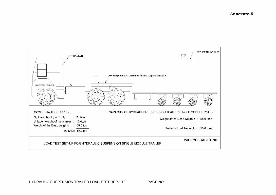
HYDRAULIC SUSPENSION TRAILER LOAD TEST REPORT PAGE NO
LOAD TESTING OF HYDRAULIC SUSPENSION TRAILERS (GOLDHOFER/COMETTO TRAILER)
I. Equipment Details:
1.1 GOLDHOFER TRAILER-1 VALF/HT/65T/01
WORK STATION- A GOLDHOFER TRAILER-2 VALF/HT/65T/01
GOLDHOFER TRAILER-3 VALF/HT/65T/01
COMETTO TRAILER-1 VALF/HT/70T/01
COMETTO TRAILER-1 SPROB/HT/70T/01 WORK STATION-B
1.2 Capacity 65t/70T Payload
1.3 Load Test venue
1.4 Date
II. Pre-Checks of trailer: Check the 15t Flat Bed Air suspension trailer and Hauler as per the daily checklist III. No load performance of Hauler & Trailer:
Sl No Item Status
01 Connect the Hauler and Trailer – adjust the steering wedge play (Tighten fully with hand and loosen 1/4th turn)
02 Start the Hauler engine and pressurize the trailer and hauler lines and ensure release of parking/ fail-safe brakes
03 Start the power pack and adjust the trailer platform
level at four corners to the operating level 1165mm± 10mm
04 Check the alignment of trailer wheels and readjust if required.
05 In no load condition, take the hauler and trailer for a road trial, check the performance
IV. Materials Required
Sl No Item Qty Status
1. Dead Weight Concrete block
15t block -4no 5ton – 1 block
Total: 55.0t
2. Four legged Handling sling for the above blocks (80t)
1 No
3. Crane facility for loading the block 1 No
4. Felt pieces As required
5. Steel Rule 1 No.
6. 15m tape 1 No.
7. Square Steel plates 4 nos

Annexure-5
HYDRAULIC SUSPENSION TRAILER LOAD TEST REPORT PAGE NO
Sl No Item Qty Status
8. permanent marker 1 no
V. Procedure:
Sl No Item Status
01 Take the hauler and trailer to the facility where the concrete blocks and EOT crane facility are available for loading of concrete blocks (weight = 55t)
02 Spread the felt pieces on the trailer to have even seating of the concrete blocks.
03 Load the concrete blocks by using the EOT crane / Crane / Forklift as per the scheme: VALF/MHS/T&E/HT/70T
04 Park the trailer on level ground and note down the heights of the trailer on four corners of the platform.
04 Check for any abnormality and leaks at pipe lines, hoses and couplings in loaded condition
05 If no abnormality is observed check the performance of the hauler and trailer under loaded condition and record.
VI. Heights of the trailer platform:
S.No Description Initial level Final Level
Remarks
1 55 t loaded on single module GH trailer, level shall be checked from top edge of the platform to ground
FR FR
2 FL FL
3 RR RR
4 RL RL
NOTE: FR – FRONT RIGHT FL: FRONT LEFT; RR – REAR RIGHT; RL – REAR LEFT VII. Line Pressure checks are made as Follows:
S.No
Description Unladen Laden Remarks
1
Pressure Gauge Readings (bar)
FR FR
2 FL FL
3 RR RR
4 RL RL

Annexure-5
HYDRAULIC SUSPENSION TRAILER LOAD TEST REPORT PAGE NO
VIII. General Observations:
S.No Description Unladen Laden Remarks
1 Lifting & Lowering of gooseneck
2 Lifting & Lowering of Rear Left side of trailer
3 Lifting & Lowering of Rear Right side of trailer
4 RH Steering of the trailer at standstill condition
5 LH Steering of the trailer at standstill condition
6 RH Steering of the trailer in normal movement
7 LH Steering of the trailer in normal movement
IX. Performance of the Hauler & Trailer
Sl No Description Observations
No load With load
1. Engine Parameters: Eng Oil Pressure - Idling (between 1.0 and 3.0 bar) Eng Oil Pressure at Operating speed (between 3.0 and 5.5 bar) Radiator coolant Temp Maximum (Indicator needle should be in green zone)
2. Charging System : Should show charging Deflection of pointer to +ve side
3. Clutch - Engagement & disengagement
4. Transmission - Engagement & Disengagement of
gears. - For any abnormal noise
5. Steering (Hauler & Trailer) - Function of steering on both sides. - For any other abnormal noise

Annexure-5
HYDRAULIC SUSPENSION TRAILER LOAD TEST REPORT PAGE NO
Sl No Description Observations
No load With load
6. Brakes ( Hauler & Trailer) Service Brakes - Function of brakes on all wheels. - Effectiveness of brakes Parking Brakes - Effectiveness of brakes
7. Climbing Gradient: (1 in 10) - Performance of the Equipment
8. For any leaks at hose connections
9. Function of 5th wheel coupling
Engagement
Disengagement
X. Maintenance Details: Hauler::
Type of maintenance scheduled Monthly, half yearly & Annual
Maintenance last attended
Next maintenance due
GOLD HOFER/COMETTO Trailer::
Type of maintenance scheduled Quarterly & Annual
Maintenance last attended
Next maintenance due
Certified that the above Equipment are cleared for operation Date: Engineer, MHS Engineer, QRG
Annexure-5
HYDRAULIC SUSPENSION TRAILER LOAD TEST REPORT PAGE NO

Annexure-5
15t Pneumatic suspension trailer Page No:
15T AIR SUSPENSION TRAILER - LOAD TEST REPORT
1. Equipment Details:
1.1 15t Air Suspension Trailer VALF/AST/15T/01 WORK STATION- A
1.2 Capacity 15t Payload
1.3 Load Test venue
1.4 Date
2. Pre-Checks of trailer: Check the 15t Flat Bed Air suspension trailer as per the daily checklist 3. Procedure for Load Testing:
Sl No Description Status
01 Park the trailer on a level ground.
02 Take the initial measurements for measuring the deflection under no load condition as shown in the sketch
03 Keep a 15t (5t concrete blocks – 3 nos) load at the center of the trailer platform as per the loading scheme: VALF/MHS/T&E/AST/15T
04 Take the measurements under loaded condition
06 Permissible Deflection (Wheel base /325) 5150/325= 14.71mm
07 Record the Deflection
08 Whether the deflection is with in the limits?
09 Previous year deflection
10 Raise all four landing legs
Take the trailer for road test in loaded condition and test the performance of the trailer for the following. - Free rotation of wheels without any binding and
wobbling - Function of Turn table for free operation on both
left and right directions. - Function of tow bar & spring. - Effectiveness of brakes. Suspension System: - The suspension control valve should exhaust the
air in the bellows when wheel happen to climb a heap.
- The suspension Control valve should admit air into bellows when the wheels fall into road pit.
- For any abnormality

Annexure-5
15t Pneumatic suspension trailer Page No:
4. Maintenance Details:
Type of maintenance scheduled Half yearly / Annual
Maintenance last attended
Next Maintenance Due
Load test results are found Satisfactory. Date: Contractor’s Supervisor Engineer-in-charge

Annexure-5
15t Pneumatic suspension trailer Page No:

Annexure-5
10T AIR SUSPENSION TRAILER Page No:
LOAD TEST REPORT OF 10T AIR SUSPENSION TRAILER
1. Equipment Details:
1.1 10t Air Suspension Trailer VALF/AST/10T/01 WORK STATION- A
1.2 Capacity 10t Payload
1.3 Load Test venue
1.4 Date
2. Pre-Checks of trailer: Check the 10t Flat Bed Air suspension trailer and Hauler as per the daily checklist 3. Procedure for Load Testing:
Sl No.
Description Status
1. Connect the hauler and check for no load performance (The hauler to be used)
2. If no load performance is satisfactory, keep the trailer for loading.
3. Take the measurements of the trailer platform as per the details given in the sketch in no load condition for calculating the deflection
4. Load 10t (5T concrete blocks – 2 nos) so that the load is equally shared on the trailer platform as per the scheme: VALF/MHS/T&E/AST/10T.
5. Take the measurements of the trailer platform as per the details given in the sketch in loaded condition for calculating deflection
6. Calculate the deflection as per the procedure given in the sketch and record.
7. Take the hauler and trailer for road trial and check the performance of the trailer for the items mentioned in the sketch and record.
8. After the road trial, remove the load. Take measurements of the trailer platform again as per the details given in the sketch compare with the measurements taken to verify that there is no permanent set
9. Check the trailer platform and parts physically that no permanent deformation has taken place.
4. TRAILER OPERATIONAL CHECKS:
Sl No
SYSTEM
Status
No Load With Load (10.0T)
1. DEFLECTION CALCULATION
2. CLH = Height of the platform at ( C) on
left side
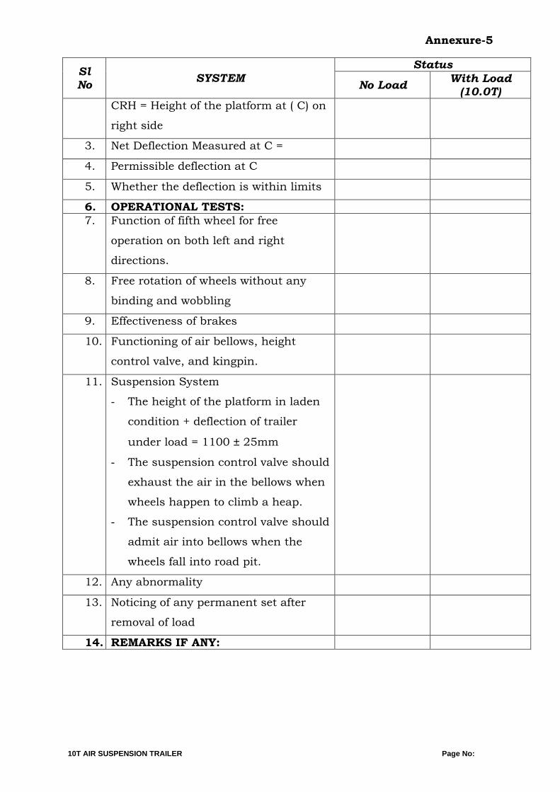
Annexure-5
10T AIR SUSPENSION TRAILER Page No:
Sl No
SYSTEM
Status
No Load With Load (10.0T)
CRH = Height of the platform at ( C) on
right side
3. Net Deflection Measured at C =
4. Permissible deflection at C
5. Whether the deflection is within limits
6. OPERATIONAL TESTS:
7. Function of fifth wheel for free
operation on both left and right
directions.
8. Free rotation of wheels without any
binding and wobbling
9. Effectiveness of brakes
10. Functioning of air bellows, height
control valve, and kingpin.
11. Suspension System
- The height of the platform in laden
condition + deflection of trailer
under load = 1100 ± 25mm
- The suspension control valve should
exhaust the air in the bellows when
wheels happen to climb a heap.
- The suspension control valve should
admit air into bellows when the
wheels fall into road pit.
12. Any abnormality
13. Noticing of any permanent set after
removal of load
14. REMARKS IF ANY:

Annexure-5
10T AIR SUSPENSION TRAILER Page No:
VI Maintenance Details:
Type of maintenance scheduled Monthly, quarterly, Annual
Maintenance last attended
Next Maintenance Due
Load test results are found Satisfactory.
Date: Contractor’s Supervisor Engineer-in-charge

Annexure-5
10T AIR SUSPENSION TRAILER Page No:
Annexure-5
18t Pneumatic suspension trailer Page No:
18T AIR SUSPENSION TRAILER - LOAD TEST REPORT I. EQUIPMENT DETAILS:
1.1 18t Air Suspension Trailer VALF/FT/18T/01 WORK STATION- A
1.2 Capacity 18t Payload
1.3 Load Test venue
1.4 Date
II. Pre-Checks of trailer: Check the 18t Flat Bed Air suspension trailer and Hauler as per the daily checklist III Procedure for Load Testing:
Sl No Description Status
01 Park the trailer on a level ground.
02 Take the initial measurements for measuring the deflection under no load condition as shown in the sketch
03 Keep a 18t (3 Concrete blocks & 2 MST wheels) load at the center of the trailer platform as per the loading scheme: VALF/MHS/T&E/AST/18T
04 Take the measurements under loaded condition
05 Permissible Deflection (Wheel base /325) 11850/325= 36.46mm
06 Measured Deflection
07 Whether the deflection is with in the limits?
08 Previous Year measured Deflection
09 Raise all four landing legs
Take the trailer for road test in loaded condition and test the performance of the trailer for the following. - Free rotation of wheels without any binding and
wobbling - Function of Turn table for free operation on both left
and right directions. - Function of tow bar & spring. - Effectiveness of brakes. Suspension System: - The suspension control valve should exhaust the air
in the bellows when wheel happen to climb a heap. - The suspension Control valve should admit air into
bellows when the wheels fall into road pit. - For any abnormality
V Maintenance Details:
Type of maintenance scheduled Half yearly / Annual
Maintenance last attended
Next Maintenance Due
Certified that the above Equipment is cleared for operation Date: Engineer, MH Engineer, QRG

Annexure-5
18t Pneumatic suspension trailer Page No:

Annexure-5
10T FLATBED TRAILER Page No:
LOAD TEST REPORT OF 10T FLAT BED TRAILER
1. Equipment Details:
1.1 10t Flat Bed Full Trailer VALF/FT/10T/01 WORK STATION- A
1.2 Capacity 10t Payload
1.3 Load Test venue
1.4 Date
2. Pre-Checks of trailer: Check the 10t Flat Bed Full Trailer and Hauler as per the daily checklist 3. No load Performance of the trailer:
S.No Description Status
1. Connect the hauler and check the trailer - Function of turntable for free operation on both Left & right directions. - Free rotation of wheels without any binding and wobbling - Action of toe bar spring and anchoring points - For any abnormality
4. Material required for Load testing:
Sl.No Item Qty Status
6.1 5t Concrete blocks 2 nos
6.2 Steel rule 1 no
6.3 MS plate 4 nos
6.4 Measuring tape 1no
6.5 Chalk piece or scriber A.R
6.6 Nylon thread required length
5.Procedure:
Sl No.
Description Status
7.1 Park the trailer on a level ground.
7.2 Take the initial measurements for measuring the deflection under no load condition as shown in the sketch.
7.3 Keep 5 ton blocks- 2 nos load at the centre of the trailer platform.
7.4 Take the measurements under loaded condition.
7.5 Calculate the Deflection as per the procedure as per the procedure given in the sketch & Record.
7.6 Total Deflection measured
7.7 Permissible deflection (Wheel Base / 325)

Annexure-5
10T FLATBED TRAILER Page No:
Sl
No.
Description Status
6950/325 = 21.385 mm
7.8 Whether the deflection is within the limits?
7.9 Previous year deflection measured in mm
8.0 After measuring the deflection, remove the load and take the measurements again and compare with the initial measurements taken to verify that there is no permanent set.
8.1 Place the load again in the same position
8.2 Take the trailer for the road test in loaded condition and test the performance of the trailer for the following.
- Function of turntable for free operation on both left & right directions.
- Free rotation of wheels without any binding and wobbling.
- Action of the Toe bar spring & anchoring points. - For any abnormality.
VI Maintenance Details:
Type of maintenance scheduled Monthly, quarterly, Annual
Maintenance last attended
Next Maintenance Due
Load test results are found Satisfactory. Date: Contractor’s Supervisor Engineer-in-charge

Annexure-5
10T FLATBED TRAILER Page No:

Annexure-5
8T FLATBED TRAILER Page No:
LOAD TEST REPORT OF 8T FLAT BED TRAILER
1. Equipment Details:
1.1 8t Flat Bed Full Trailer VALF/FT/8T/01 WORK STATION- A
1.2 Capacity 8t Payload
1.3 Load Test venue
1.4 Date
2. Pre-Checks of trailer: Check the 8t Flat Bed Full Trailer and Hauler as per the daily checklist
3. No load Performance of the trailer:
Sl No.
Description Status
1. Connect the hauler and check the trailer - Function of turntable for free operation on both Left & right directions. - Free rotation of wheels without any binding and wobbling - Action of toe bar spring and anchoring points - For any abnormality
4. Material required for Load testing:
Sl.No Item Qty Status
1. 5t Concrete block & MST Wheels 1 no & 2 nos
2. Steel rule 1 no
3. MS plate 150mmX 150mm 4 nos
4. Measuring tape 1no
5. Chalk piece or scriber A.R
5.Procedure:
S.No Description Status
1 Park the trailer on a level ground.
2 Take the initial measurements for measuring the deflection under no load condition as shown in the sketch.
3 Keep 5 ton blocks- 1 no and MST wheels 02 nos load at the centre of the trailer platform as per the Load test scheme
4 Take the measurements under loaded condition.
5 Calculate the Deflection as per the procedure as per the procedure given in the sketch & Record.
6 Total Deflection measured
7 Permissible deflection (Wheel Base / 325) 1600/325 = 4.90 mm

Annexure-5
8T FLATBED TRAILER Page No:
S.No Description Status
8 Whether the deflection is within the limits?
9 Previous year deflection measured in mm
10 After measuring the deflection, remove the load and take the measurements again and compare with the initial measurements taken to verify that there is no permanent set.
11 Place the load again in the same position
12 Take the trailer for the road test in loaded condition and test the performance of the trailer for the following.
- Function of turntable for free operation on both left & right directions.
- Free rotation of wheels without any binding and wobbling.
- Action of the Toe bar spring & anchoring points. - For any abnormality.
Maintenance Details:
Type of maintenance scheduled Half yearly / Annual
Maintenance last attended
Next Maintenance Due
Certified that the above Equipment is cleared for operation Date: Contract Supervisor Engineer, MHS

Annexure-5
8T FLATBED TRAILER Page No:

Annexure-5
20T BOWL TRAILER Page No:
LOAD TEST REPORT OF 20t BOWL TRAILER
1. Equipment Details:
1.1 Low Bed Trailer WORK STATION- B
1.2 Capacity 20t PAYLOAD
1.3 Load Test venue
1.4 Date
2. Pre-Checks of trailer: Check the 20t capacity Bowl Trailer and Hauler as per the daily checklist
3. No load Performance of the trailer:
Sl No.
Description Status
1. Connect the hauler and check the trailer - Function of turntable for free operation on both Left & right directions. - Free rotation of wheels without any binding and wobbling - Action of toe bar spring and anchoring points - For any abnormality
4. Material required for Load testing:
Sl.No Item Qty Status
1. 5t Concrete blocks 4 nos
2. Steel rule 1 no
3. MS plate 150mmX 150mm 4 nos
4. Measuring tape 1no
5. Chalk piece or scriber A.R
5. Procedure:
S.No Description Status
1 Park the trailer on a level ground.
2 Take the initial measurements for measuring the deflection under no load condition as shown in the sketch.
3 Keep 5t block- 4 nos and load at the centre of the trailer platform as per the Load test scheme: SPROB/MHS/T&E/FT/20T
4 Take the measurements under loaded condition.
5 Calculate the Deflection as per the procedure as per the procedure given in the sketch & Record.
6 Total Deflection measured
7 Permissible deflection (Wheel Base / 325)
8 Whether the deflection is within the limits?

Annexure-5
20T BOWL TRAILER Page No:
S.No Description Status
9 Previous year deflection measured in mm
10 After measuring the deflection, remove the load and take the measurements again and compare with the initial measurements taken to verify that there is no permanent set.
11 Place the load again in the same position
12 Take the trailer for the road test in loaded condition and test the performance of the trailer for the following.
- Function of turntable for free operation on both left & right directions.
- Free rotation of wheels without any binding and wobbling.
- Action of the Toe bar spring & anchoring points. - For any abnormality.
Maintenance Details:
Type of maintenance scheduled Half yearly / Annual
Maintenance last attended
Next Maintenance Due
Certified that the above Equipment is cleared for operation Date: Contract Supervisor Engineer, MHS

Annexure-5
20T BOWL TRAILER Page No:

Annexure-5
15t Flat bed trailer Load test report Page No:
LOAD TEST REPORT FOR 15 TON FLAT BED TRAILER
1. Equipment Details:
1.1 15t Air Suspension Trailer VALF/FT/15T/01 WORK STATION- A
1.2 Capacity 15t Payload
1.3 Load Test venue
1.4 Date
2. Pre-Checks of trailer: Check the 15t Flat Bed Air suspension trailer and Hauler as per the daily checklist 3. No load Performance of the trailer:
Sl No Description Status
01 Connect the hauler and check the trailer
- Function of Turn Table for free operation on both left and right directions.
- Free rotation of wheels without any binding and wobbling
- Action of toe bar spring and anchoring points - For any abnormality
4. Materials Required for Load Testing
Sl No Item Qty Status
01 5t Concrete block 3 Nos.
02 Steel rule 1 No
03 Ms Plates 4 Nos.
04 Measuring tape 1 No
05 Chalk piece or scriber A.R
06 Nylon thread required length
5. Procedure:
Sl No Description Status
01 Park the trailer on a level ground.
02 Take the initial measurements for measuring the deflection under no load condition as shown in the sketch
03 Keep a 5t block-3nos load at the center of the trailer platform as per the load test scheme
04 Take the measurements under loaded condition
05 Calculate the deflection as per the procedure given in the sketch and record.

Annexure-5
15t Flat bed trailer Load test report Page No:
Sl No Description Status
06 Total Deflection measured
07 Permissible Deflection (Wheel base /325) 5950/325= 18.3 mm
08 Whether the deflection is with in the limits?
09 Previous year deflection measured (mm)
10 After measuring of deflection, remove the load moment and take the measurements again and compare with the initial measurements taken to verify that there is no permanent set .
11 Place the load again in the same position
12 Take the trailer for road test in loaded condition and test the performance of the trailer for the following. - Function of turntable for free operation on
both left and right directions. - Free rotation of wheels without any binding
and wobbling - Action of toe bar spring and anchoring points - For any abnormality
6. Maintenance Details:
Type of maintenance schedule Half yearly & Annual
Maintenance last attended
Next maintenance due
Load test results are found Satisfactory.
Date: Contractor’s Supervisor Engineer-in-charge

Annexure-5
15t Flat bed trailer Load test report Page No:

Annexure-5
AP BIN TRAILER Page No:
LOAD TEST REPORT OF AP BIN TRAILERS
1. Equipment Details:
1.1
AP BIN Trailer SXC 4005
WORK STATION- B AP BIN Trailer SXC 4105
AP BIN Trailer
AP BIN Trailer
1.2 Capacity 5t Payload
1.3 Load Test venue
1.4 Date
2. Pre-Checks of trailer: Check the 5t capacity AP bin Full Trailer and Hauler as per the daily checklist 3. No load Performance of the trailer:
Sl
No. Description Status
1. Connect the hauler and check the trailer
- Function of turntable for free operation on both Left & right directions. - Free rotation of wheels without any binding and wobbling - Action of toe bar spring and anchoring points - For any abnormality
4. Material required for Load testing:
Sl.No Item Qty Status
1. 5t Concrete block 1 no
2. Steel rule 1 no
3. MS plate 150mmX 150mm 4 nos
4. Measuring tape 1no
5. Chalk piece or scriber A.R
5.Procedure:
S.No Description Status
1 Park the trailer on a level ground.
2 Take the initial measurements for measuring the deflection under no load condition as shown in the sketch.
3 Keep 5ton block- 1 no and load at the centre of the trailer platform as per the Load test scheme: SPROB/MHS/T&E/FBT/5T
4 Take the measurements under loaded condition.
5 Calculate the Deflection as per the procedure as per the procedure given in the sketch & Record.
6 Total Deflection measured

Annexure-5
AP BIN TRAILER Page No:
S.No Description Status
7 Permissible deflection (Wheel Base / 325)
8 Whether the deflection is within the limits?
9 Previous year deflection measured in mm
10 After measuring the deflection, remove the load and take the measurements again and compare with the initial measurements taken to verify that there is no permanent set.
11 Place the load again in the same position
12 Take the trailer for the road test in loaded condition and test the performance of the trailer for the following.
- Function of turntable for free operation on both left & right directions.
- Free rotation of wheels without any binding and wobbling.
- Action of the Toe bar spring & anchoring points. - For any abnormality.
Maintenance Details:
Type of maintenance scheduled Half yearly / Annual
Maintenance last attended
Next Maintenance Due
Certified that the above Equipment is cleared for operation Date: Contract Supervisor Engineer, MHS

Annexure-5
AP BIN TRAILER Page No:

Annexure-5
APPLE FULL TRAILER Page No:
LOAD TEST REPORT OF APPLE TRAILERS
1. Equipment Details:
1.1 APPLE Trailer – 8 SXC 3101
WORK STATION- B APPLE Trailer – 10 SXC 3301
1.2 Capacity 1t Payload
1.3 Load Test venue
1.4 Date
2. Pre-Checks of trailer: Check the 1t capacity Apple Full Trailer and Hauler as per the daily checklist 3. No load Performance of the trailer:
Sl No.
Description Status
1. Connect the hauler and check the trailer - Function of turntable for free operation on both Left & right directions. - Free rotation of wheels without any binding and wobbling - Action of toe bar spring and anchoring points - For any abnormality
4. Material required for Load testing:
Sl.No Item Qty Status
1. 1t Concrete block 1 no
2. Steel rule 1 no
3. MS plate 150mmX 150mm 4 nos
4. Measuring tape 1no
5. Chalk piece or scriber A.R
5.Procedure:
S.No Description Status
1 Park the trailer on a level ground.
2 Take the initial measurements for measuring the deflection under no load condition as shown in the sketch.
3 Keep 1ton block- 1 no and load at the centre of the trailer platform as per the Load test scheme: SPROB/MHS/T&E/FBT-1/1T
4 Take the measurements under loaded condition.
5 Calculate the Deflection as per the procedure as per the procedure given in the sketch & Record.
6 Total Deflection measured
7 Permissible deflection (Wheel Base / 325)

Annexure-5
APPLE FULL TRAILER Page No:
S.No Description Status
1000/325 = 3.07 mm
8 Whether the deflection is within the limits?
9 Previous year deflection measured in mm
10 After measuring the deflection, remove the load and take the measurements again and compare with the initial measurements taken to verify that there is no permanent set.
11 Place the load again in the same position
12 Take the trailer for the road test in loaded condition and test the performance of the trailer for the following.
- Function of turntable for free operation on both left & right directions.
- Free rotation of wheels without any binding and wobbling.
- Action of the Toe bar spring & anchoring points. - For any abnormality.
Maintenance Details:
Type of maintenance scheduled Half yearly / Annual
Maintenance last attended
Next Maintenance Due
Certified that the above Equipment is cleared for operation Date: Contract Supervisor Engineer, MHS

Annexure-5
APPLE FULL TRAILER Page No:

APPLE FULL TRAILER Page No:
LOAD TEST REPORT OF APPLE TRAILERS
1. Equipment Details:
1.1
APPLE Trailer – 1 1SXC 1601
WORK STATION- B
APPLE Trailer – 2 SXC 1801
APPLE Trailer – 3 SXC 2201
APPLE Trailer – 4 SXC 2301
APPLE Trailer – 5 SXC 2501
APPLE Trailer – 6 SXC 2601
APPLE Trailer – 7 SXC 3001
APPLE Trailer – 9 SXC 3201
1.2 Capacity 1t Payload
1.3 Load Test venue
1.4 Date
2. Pre-Checks of trailer: Check the 1t capacity Apple Full Trailer and Hauler as per the daily checklist 3. No load Performance of the trailer:
Sl
No. Description Status
1. Connect the hauler and check the trailer - Function of turntable for free operation on both Left & right directions. - Free rotation of wheels without any binding and wobbling - Action of toe bar spring and anchoring points - For any abnormality
4. Material required for Load testing:
Sl.No Item Qty Status
1. 1t Concrete block 1 no
2. Steel rule 1 no
3. MS plate 150mmX 150mm 4 nos
4. Measuring tape 1no
5. Chalk piece or scriber A.R
5.Procedure:
S.No Description Status
1 Park the trailer on a level ground.
2 Take the initial measurements for measuring the deflection under no load condition as shown in the sketch.
3 Keep 1ton block- 1 no and load at the centre of the trailer platform as per the Load test scheme:
SPROB/MHS/T&E/FT/1T
4 Take the measurements under loaded condition.

APPLE FULL TRAILER Page No:
S.No Description Status
5 Calculate the Deflection as per the procedure as per the procedure given in the sketch & Record.
6 Total Deflection measured
7 Permissible deflection (Wheel Base / 325) 800/325 = 2.46 mm
8 Whether the deflection is within the limits?
9 Previous year deflection measured in mm
10 After measuring the deflection, remove the load and take the measurements again and compare with the initial measurements taken to verify that there is no permanent set.
11 Place the load again in the same position
12 Take the trailer for the road test in loaded condition and test the performance of the trailer for the following.
- Function of turntable for free operation on both left & right directions.
- Free rotation of wheels without any binding and wobbling.
- Action of the Toe bar spring & anchoring points. - For any abnormality.
Maintenance Details:
Type of maintenance scheduled Half yearly / Annual
Maintenance last attended
Next Maintenance Due
Certified that the above Equipment is cleared for operation Date: Contract Supervisor Engineer, MHS

APPLE FULL TRAILER Page No:

Annexure-5
BOWL TRAILER Page No:
LOAD TEST REPORT OF BOWL TRAILERS
1. Equipment Details:
1.1 BOWL Trailer SXC 4615
WORK STATION- B BOWL Trailer – 1 SXC 2115
BOWL Trailer – 2 SXC 2915
BOWL Trailer – 3 SXC 3215
1.2 Capacity 20t GCW
1.3 Load Test venue
1.4 Date
2. Pre-Checks of trailer: Check the 15t capacity Bowl Full Trailer and Hauler as per the daily checklist 3. No load Performance of the trailer:
Sl No.
Description Status
1. Connect the hauler and check the trailer - Function of turntable for free operation on both Left & right directions. - Free rotation of wheels without any binding and wobbling - Action of toe bar spring and anchoring points - For any abnormality
4. Material required for Load testing:
Sl.No Item Qty Status
1. 1t Concrete block 1 no
2. Steel rule 1 no
3. MS plate 150mmX 150mm 4 nos
4. Measuring tape 1no
5. Chalk piece or scriber A.R
5.Procedure:
S.No Description Status
1 Park the trailer on a level ground.
2 Take the initial measurements for measuring the deflection under no load condition as shown in the sketch.
3 Keep 5ton block- 3 nos and load at the centre of the trailer platform as per the Load test scheme:
SPROB/MHS/T&E/FBT/15T
4 Take the measurements under loaded condition.
5 Calculate the Deflection as per the procedure as per the procedure given in the sketch & Record.

Annexure-5
BOWL TRAILER Page No:
S.No Description Status
6 Total Deflection measured
7 Permissible deflection (Wheel Base / 325)
8 Whether the deflection is within the limits?
9 Previous year deflection measured in mm
10 After measuring the deflection, remove the load and take the measurements again and compare with the initial measurements taken to verify that there is no permanent set.
11 Place the load again in the same position
12 Take the trailer for the road test in loaded condition and test the performance of the trailer for the following.
- Function of turntable for free operation on both left & right directions.
- Free rotation of wheels without any binding and wobbling.
- Action of the Toe bar spring & anchoring points. - For any abnormality.
Maintenance Details:
Type of maintenance scheduled Half yearly / Annual
Maintenance last attended
Next Maintenance Due
Certified that the above Equipment is cleared for operation Date: Contract Supervisor Engineer, MHS

Annexure-5
BOWL TRAILER Page No:

Annexure-5
LOW BED TRAILER Page No:
LOAD TEST REPORT OF LOW BED TRAILERS
1. Equipment Details:
1.1
Low Bed Trailer SXC 4202
WORK STATION- B Low Bed Trailer SXC 4302
Low Bed Trailer SXC 4402
Low Bed Trailer SXC 4802
1.2 Capacity 2t PAYLOAD
1.3 Load Test venue
1.4 Date
2. Pre-Checks of trailer: Check the 2t capacity Low bed Trailer and Hauler as per the daily checklist 3. No load Performance of the trailer:
Sl
No. Description Status
1. Connect the hauler and check the trailer
- Function of turntable for free operation on both Left & right directions. - Free rotation of wheels without any binding and wobbling - Action of toe bar spring and anchoring points - For any abnormality
4. Material required for Load testing:
Sl.No Item Qty Status
1. 2t Concrete block 1 nos
2. Steel rule 1 no
3. MS plate 150mmX 150mm 4 nos
4. Measuring tape 1no
5. Chalk piece or scriber A.R
5. Procedure:
S.No Description Status
1 Park the trailer on a level ground.
2 Take the initial measurements for measuring the deflection under no load condition as shown in the sketch.
3 Keep 2t block- 1 nos and load at the centre of the trailer platform as per the Load test scheme: SPROB/MHS/T&E/FBT/2T
4 Take the measurements under loaded condition.
5 Calculate the Deflection as per the procedure as per the procedure given in the sketch & Record.
6 Total Deflection measured

Annexure-5
LOW BED TRAILER Page No:
S.No Description Status
7 Permissible deflection (Wheel Base / 325)
8 Whether the deflection is within the limits?
9 Previous year deflection measured in mm
10 After measuring the deflection, remove the load and take the measurements again and compare with the initial measurements taken to verify that there is no permanent set.
11 Place the load again in the same position
12 Take the trailer for the road test in loaded condition and test the performance of the trailer for the following.
- Function of turntable for free operation on both left & right directions.
- Free rotation of wheels without any binding and wobbling.
- Action of the Toe bar spring & anchoring points. - For any abnormality.
Maintenance Details:
Type of maintenance scheduled Half yearly / Annual
Maintenance last attended
Next Maintenance Due
Certified that the above Equipment is cleared for operation Date: Contract Supervisor Engineer, MHS

Annexure-5
LOW BED TRAILER Page No:

Annexure-5
AP BIN TRAILER Page No:
LOAD TEST REPORT OF LOW BED TRAILERS
1. Equipment Details:
1.1 Low Bed Trailer SXC 2820 WORK STATION- B
1.2 Capacity 20t PAYLOAD
1.3 Load Test venue
1.4 Date
2. Pre-Checks of trailer: Check the 20t capacity Low bed Trailer and Hauler as per the daily checklist 3. No load Performance of the trailer:
Sl No.
Description Status
1. Connect the hauler and check the trailer - Function of turntable for free operation on both Left & right directions. - Free rotation of wheels without any binding and wobbling - Action of toe bar spring and anchoring points - For any abnormality
4. Material required for Load testing:
Sl.No Item Qty Status
1. 5t Concrete blocks 4 nos
2. Steel rule 1 no
3. MS plate 150mmX 150mm 4 nos
4. Measuring tape 1no
5. Chalk piece or scriber A.R
5. Procedure:
S.No Description Status
1 Park the trailer on a level ground.
2 Take the initial measurements for measuring the deflection under no load condition as shown in the sketch.
3 Keep 5t block- 4 nos and load at the centre of the trailer platform as per the Load test scheme:
SPROB/MHS/T&E/FBT/20T
4 Take the measurements under loaded condition.
5 Calculate the Deflection as per the procedure as per the procedure given in the sketch & Record.
6 Total Deflection measured
7 Permissible deflection (Wheel Base / 325)
8 Whether the deflection is within the limits?

Annexure-5
AP BIN TRAILER Page No:
S.No Description Status
9 Previous year deflection measured in mm
10 After measuring the deflection, remove the load and take the measurements again and compare with the initial measurements taken to verify that there is no permanent set.
11 Place the load again in the same position
12 Take the trailer for the road test in loaded condition and test the performance of the trailer for the following.
- Function of turntable for free operation on both left & right directions.
- Free rotation of wheels without any binding and wobbling.
- Action of the Toe bar spring & anchoring points. - For any abnormality.
Maintenance Details:
Type of maintenance scheduled Half yearly / Annual
Maintenance last attended
Next Maintenance Due
Certified that the above Equipment is cleared for operation Date: Contract Supervisor Engineer, MHS

Annexure-5
AP BIN TRAILER Page No:

Annexure-5
PS0 XL TRAILER Page No:
LOAD TEST REPORT OF PS0 XL TRAILER
1. Equipment Details:
1.1 WELL BED TRAILER SXC 4825 WORK STATION- B
1.2 Capacity 25t Payload
1.3 Load Test venue
1.4 Date
2. Pre-Checks of trailer: Check the 25t capacity Well Bed trailer and Hauler as per the daily checklist 3. No load Performance of the trailer:
Sl No.
Description Status
1. Connect the hauler and check the trailer - Function of turntable for free operation on both Left & right directions. - Free rotation of wheels without any binding and wobbling - Action of toe bar spring and anchoring points - For any abnormality
4. Material required for Load testing:
Sl.No Item Qty Status
1. 5t Concrete blocks 5 nos
2. Steel rule 1 no
3. MS plate 150mmX 150mm 4 nos
4. Measuring tape 1no
5. Chalk piece or scriber A.R
5. Procedure:
S.No Description Status
1 Park the trailer on a level ground.
2 Take the initial measurements for measuring the deflection under no load condition as shown in the sketch.
3 Keep 5t blocks- 5 no and load at the centre of the trailer platform as per the Load test scheme: SPROB/MHS/T&E/WBT/25T
4 Take the measurements under loaded condition.
5 Calculate the Deflection as per the procedure as per the procedure given in the sketch & Record.
6 Total Deflection measured
7 Permissible deflection (Wheel Base / 325)

Annexure-5
PS0 XL TRAILER Page No:
S.No Description Status
8 Whether the deflection is within the limits?
9 Previous year deflection measured in mm
10 After measuring the deflection, remove the load and take the measurements again and compare with the initial measurements taken to verify that there is no permanent set.
11 Place the load again in the same position
12 Take the trailer for the road test in loaded condition and test the performance of the trailer for the following.
- Function of turntable for free operation on both left & right directions.
- Free rotation of wheels without any binding and wobbling.
- Action of the Toe bar spring & anchoring points. - For any abnormality.
Maintenance Details:
Type of maintenance scheduled Half yearly / Annual
Maintenance last attended
Next Maintenance Due
Certified that the above Equipment is cleared for operation Date: Contract Supervisor Engineer, MHS

Annexure-5
PS0 XL TRAILER Page No:

ANNEXURE – 6 LIST OF MINOR BREAKDOWNS

Annexure-6
LIST OF MINOR BREAKDOWN / REPAIR WORKS
ENGINE, CLUTCH, STEERING, BRAKES AND GENERAL VEHICLE SYSTEMS
SL No. Type of break down / Repair activities
1. Fan belt replacement
2. Replacement of radiator hoses
3. Removing and changing of radiator assembly
4. Diesel and oil pipes changing
5. Minor radiator repairs
6. Removal and fitment of Water pump assembly
7. Changing of water pump kit
8. Removal and fitment of FIP injectors
9. Removal and fitment of FI Pump Assembly
10. Removing and changing of cylinder head and changing of head gasket
11. Removing and refitting exhaust pipes for repairs
12. Removing and refitting of clutch units and changing of clutch plates
13. Replacement of Propeller Shaft Universal Joint crosses
14. Replacement of Propeller Shaft Center Joint bearing
15. Replacing of unloader valve kit
16. Replacing of check valve kit
17. Replacing of tyre inflator kit
18. Replacing of brake chamber diaphragm
19. Replacing palm coupling / kit
20. Replacing foot pedal valve kit
21. Replacing of Speedo meter / hour meter cable
22. Replacing of Master Cylinder Kit and bleeding
23. Replacing of Wheel Cylinder kits and bleeding
24. Removing of diesel tank, cleaning, repairing and fitment
HYDRAULIC SYSTEM
SL No. Type of break down / Repair activities
1. Replacing of hoses and connected fittings and filters
2. Removing and refitting of hydraulic drive pump assembly
3. Replacing of hydraulic pump kits
4. Removing and refitting of control valve assembly
5. Replacing of control valve service kits
6. Replacing of check valve assembly
7. Replacing of check valve kit
8. Removing of hoist cylinder, changing of kit and refitting to the equipment
9. Removing of tilt cylinder, changing of kit and refitting to the equipment
10. Removing and replacing of steering cylinder
11. Replacing of steering repair kit
12. Removing and cleaning of transmission oil strainer and refitting
ELECTRICAL SYSTEM
SL No. Type of break down / Repair activities
1. Replacing of Battery
2. Soldering of battery clamps & terminals
3. Battery pole replacement
4. Replacing of ignition switch and other switches
5. Removal and fitment of Head light assemblies
7. Removing and refitting of generator / alternator
8. Adjusting regulator settings
9. Replacing of regulator assembly
10. Removal and fitment of horn assemblies
11. Attending to the repairs of horn and tuning
12. Attending to self motor problems and overhauling
13. Attending to dynamo / alternator problems and overhauling

Annexure-6
LIST OF MINOR BREAKDOWN / REPAIR WORKS
14. Fixing of extra light fittings as per requirement
15. Adjusting head light focus
16. Reconditioning of self motor solenoid switches
OTHER ELECTRICAL SYSTEM
SL No. Type of break down / Repair activities
1. Mixing of battery acid, making the new dry battery ready for charging and charging
2. Reconditioning of self motor and dynamo / alternator armatures with new winding and commutator setting
3. Providing new insulation tape to filed coils of self motor and dynamo / alternator, varnishing and fitting back.

ANNEXURE – 7 PAINTING EQUIPMENT

ANNEXURE-7
1 of 9 | P a g e
PAINTING OF MATERIAL HANDLING EQUIPMENT WORKSTATION – A (VALF)
Sl.NO EQUIPMENT NAME & EQUIPMENT NUMBER
1. 2T GODREJ FORKLIFT VALF/FL/2T/01
2. 3T GODREJ FORKLIFT-1 VALF/FL/3T/01
3. 3T GODREJ FORKLIFT-2 VALF/FL/3T/02
4. 3T GODREJ FORKLIFT-3 VALF/FL/3T/03
5. 5T GODREJ FORKLIFT VALF/FL/5T/01
6. 10T GODREJ FORKLIFT VALF/FL/10T/01
7. 16T VOLTAS FORKLFIT VALF/FL/16T/01
8. EICHER TRACTOR-1 VALF/HA/15T/01
9. EICHER TRACTOR-2 VALF/HA/15T/02
10. EICHER TRACTOR-3 VALF/HA/15T/03
11. EICHER TRACTOR-4 VALF/HA/15T/04
12. ASHOK LEYLAND HIPPO HAULER 1/13, VALF/HA/49T/01
13. ASHOK LEYLAND HIPPO HAULER ¼ VALF/HA/49T/02
14. VOLVO HAULER -1 VALF/HA/49T/03
15. VOLVO HAULER -2 VALF/HA/49T/04
16. VOLVO HAULER -3 VALF/HA/49T/05
17. AMW HAULER - 1 VALF/HA/49T/06
18. AMW HAULER - 2 VALF/HA/49T/07
19. TATA PRIMA HAULER VALF/HA/49T/08
20. 70T BEML HAULER - 1 VALF/HA/70T/01
21. 70T BEML HAULER - 2 VALF/HA/70T/02
22. TATA ACE CYLINDER TRANSPORTER AP 26 X 7113
23. TATA ACE AGNI MOTOR TRANSPORTER AP 26 X 7116 24. TATA ACESAMPLE PROPELLANT TRANSPORTER , AP 26 TT 4189
25. TATA 407 MINI EXPLOSIVE VAN AP26 TT 0510

ANNEXURE-7
2 of 9 | P a g e
Sl.NO EQUIPMENT NAME & EQUIPMENT NUMBER
26. TATA UPLINK VEHICLE
27. TATA 807 SAFETY VAN, AP26 T 2240
28. TATA 709 SAFETY VAN, AP26 X 7114
29. TATA 709 EXINDUSTIAL MINI TRUCK, AP26 W 9868
30. TATA 1210 E PLATFORM TRUCK AP26 T 791
31. TATA 1613 EXPLOSIVE VAN AP26 X 1954
32. 10T HYDRA PICK ‘N’ CARRY CRANE VALF/MC/10T/01
33. 15T TYRE MOUNTED TIL CRANE VALF/MC/15T/01
34. 10T AIR SUSPENSION TRAILER VALF/ST/AST/10T/01
35. 15T AIR SUSPENSION TRAILER VALF/FT/AFT/15T/01
36. 18T AIR SUSPENSION TRAILER VALF/AST/18T/01
37. GOLDHOFER TRAILER-2 VALF/HT/65T/02
38. GOLDHOFER TRAILER-3 VALF/HT/65T/03
39. COMETTO TRAILER-1 VALF/HT/70T/01
40. 4T FLAT BED FULL TRAIER VALF/FT/4T/01
41. 5T FLAT BED FULL TRAILER VALF/FT/5T/01
42. 8T FLAT BED FULL TRAILER VALF/FT/8T/01
43. 10T FLAT BED FULL TRAILER-1 VALF/FT/10T/01
44. 10T FLAT BED FULL TRAILER-2 VALF/FT/10T/02
45. 10T WELL BED TRAILER-1 VALF/LT/10T/01
46. 10T WELL BED TRAILER-2 VALF/LT/10T/02
47. 15T FLAT BED FULL TRAILER-1 VALF/FT/15T/01
48. 15T FLAT BED FULL TRAILER-2 VALF/FT/15T/02
49. 30T DEAD WEIGHT TRANSPORTER VALF/FT/30T/01
50. 30T FLAT BED SEMI TRAILER VALF/ST/30T/01
51. PS0 TRANSTILT
VALF/ST/PS0/01
52. CRYO TRANSTILT VALF/ST/CT/01
53. CRYO TRANSTILT C25 VALF/ST/CT/02

ANNEXURE-7
3 of 9 | P a g e
Sl.NO EQUIPMENT NAME & EQUIPMENT NUMBER
54. L40 TRANSTILT VALF/ST/L40/01
55. L110 TRANSTILT VALF/ST/L110/01
56. PS0M – XL TRANSTILT VALF/ST/PS0-XL/01
57. 12T SEMI TRAILER – 1 VALF/HAT/N2-2X2/01
58. 12T SEMI TRAILER – 2 VALF/HAT/N2-2X2/02
59. LIQUID HYDROGEN TANKER-I LSSF/ST/LH-2/45CM/01
60. LIQUID HYDROGEN TANKER-II LSSF/ST/LH-2/45CM/02
61. LIQUID OXYGEN TANKER LSSF/ST/OXY/45CM/01
62. 15 KL LIQUID HYDROGEN TANKER-I LSSF/ST/LH-1/15KL/01
63. 40 KL LIQUID HYDROGEN TANKER-I LSSF/ST/LH-1/40KL/01
64. 40 KL LIQUID HELIUM TANKER-I LSSF/ST/LHE-1/40KL/01
65. ADITHYA MOTOR TRANSPORTER VALF/FT/1T/01
66. AGNI MOTOR TRAILER-1 VALF/AT/1T/01
67. AGNI MOTOR TRAILER-2 VALF/AT/1T/02
68. JEEP TRAILER-1 VALF/JT/1T/01
69. JEEP TRAILER-2 VALF/JT/1T/02
70. RH 200 TRANSPORTER VALF/FT/RH200/2T/01
71. RH 560 TRANSPORTER-2 VALF/FT/RH560/3T/01
72. RH 560 TRANSPORTER-1 VALF/FT/RH560/6T/01
73. NITROGEN TANKER (8CM) LSSF/FT/N2-8CM/01
74. 10T N2 MODULE TRAILER-I LSSF/FT/N2-10T/01
75. 10T N2 MODULE TRAILER-II LSSF/FT/N2-10T/02
76. 10T N2 MODULE TRAILER-III LSSF/FT/N2-10T/03
77. 10T N2 MODULE TRAILER-IV LSSF/FT/N2-10T/04
78. 12T SEMI TRAILER – I,CTF/N2-2X2/01
79. 12T SEMI TRAILER – II, BS/N2-2X2/02
80. 12T SEMI TRAILER – III, CTF/03
81. 12T SEMI TRAILER – IV, CTF/04
82. DM WATER TANKER – I LSSF/FT/DMW-1.5KL/0.1
83. DM WATER TANKER - II LSSF/FT/DMW-5KL/0.2
84. DM WATER TANKER - III LSSF/FT/5KL/02

ANNEXURE-7
4 of 9 | P a g e
Sl.NO EQUIPMENT NAME & EQUIPMENT NUMBER
85. 15T DM WATER TANKER – IV LSSF/ST/DMW-10KL/01
86. EFFLUENT TANKER – I LSSF/FT/EF-7KL/01
87. N2 MODULE – I LSSF/FT/N2-1X2/01
88. N2 MODULE – II LSSF/FT/N2-1X2/02
89. SITVC TANKER - 1 LPSC/FT/SITVC-5KL/01
90. SITVC TANKER -2 LPSC/FT/SITVC-5KL/02
91. PROPELLANT TRANSFER UNIT – I LSSF/FT/MON-3.5KL/01
92. PROPELLANT TRANSFER UNIT – II LSSF/FT/MMH-3.5KL/02
93. N2 MODULE TRAILER – I LSSF/FT/N2-0.5X2/01
94. 12T NITROGEN TANKER – I LSSF/ST/N2/2X2/01
95. 12T NITROGEN TANKER - II LSSF/ST/N2/2X2/02
96. NITROGEN TANKER – I LSSF/ST/N2/0.5X4/01
97. 12T HELIUM MODULE-I LSSF/ST/HE-2x2/01
98. 12T HELIUM MODULE-II LSSF/ST/HE-2x2/02
99. 12T HELIUM MODULE-III LSSF/ST/HE-1x4/01
100. IMT TANKER-1(New) N2O4 LSSF/ST/30KL/E-5003/01
101. IMT TANKER -2 N2O4 LSSF/ST/30KL/02
102. IMT TANKER -1(New) UH25 LSSF/ST/30KL/E-4003/01
103. IMT TANKER -2 UH25
LSSF/ST/30KL/02
104. RT TANKER -1 UH-25 LSSF/BS/UH-25/01
105. RT TANKER -2 UH-25 LSSF/BS/UH-25/02
106. RT TANKER -1 N2O4 LSSF/BS/N2O4/01
107. RT TANKER -2 N2O4 LSSF/BS/N2O4/02
108. MOBILE MOTR AIR SUSPENSION SEMI TRAILER 109. PS2/GS2 STAGE TRANSPORTATION TRAILER
110. BATTERY OPERATED TRUCK-1 VALF/BOT/2T/01
111. BATTERY OPERATED TRUCK-2 VALF/BOT/2T/02
112. BATTERY OPERATED TRUCK-3 VALF/BOT/2T/03

ANNEXURE-7
5 of 9 | P a g e
Sl.NO EQUIPMENT NAME & EQUIPMENT NUMBER
113. BATTERY OPERATED TRUCK-4 VALF/BOT/2T/04
114. BATTERY OPERATED TRUCK-5 VALF/BOT/2T/05
115. BATTERY OPERATED TRUCK-6 VALF/BOT/2T/06
116. BATTERY OPERATED TRUCK-7 VALF/BOT/2T/07
117. BATTERY OPERATED TRUCK-8 VALF/BOT/2T/08
118. BATTERY OPERATED TRUCK-9
VALF/BOT/2T/09
119. BATTERY OPERATED TRUCK-10 VALF/BOT/2T/10
120. BATTERY OPERATED TRUCK-11 VALF/BOT/2T/11
121. BATTERY OPERATED TRUCK-12 VALF/BOT/2T/12
122. BATTERY OPERATED TRUCK-13 VALF/BOT/2T/13
123. BATTERY OPERATED TRUCK-14 VALF/BOT/2T/14
124. BATTERY OPERATED TRUCK-15 VALF/BOT/2T/15
125. BATTERY OPERATED TRUCK-16
VALF/BOT/2T/16
126. BATTERY OPERATED TRUCK-17 VALF/BOT/2T/17
127. BATTERY OPERATED TRUCK-18 VALF/BOT/2T/18
128. BATTERY OPERATED TRUCK-19 VALF/BOT/2T/19
129. BATTERY OPERATED TRUCK-20 VALF/BOT/2T/20
130. BATTERY OPERATED TRUCK-21 VALF/BOT/2T/21
131. BATTERY OPERATED TRUCK-22
VALF/BOT/2T/22
132. BATTERY OPERATED TRUCK-23 VALF/BOT/2T/23
133. BATTERY OPERATED TRUCK-24 VALF/BOT/2T/24
134. BATTERY OPERATED TRUCK-25 VALF/BOT/2T/25
135. BATTERY OPERATED TRUCK-26 VALF/BOT/2T/26
136. BATTERY OPERATED TRUCK-27

ANNEXURE-7
6 of 9 | P a g e
Sl.NO EQUIPMENT NAME & EQUIPMENT NUMBER
VALF/BOT/2T/27
137. BATTERY OPERATED TRUCK-28 VALF/BOT/2T/28
138. BATTERY OPERATED TRUCK-29 VALF/BOT/2T/29
139. DOLLEY – 1 (2 AXLES) VALF/DL/20T/01
140. DOLLEY – 2 (2 AXLES) VALF/DL/20T/02
141. DOLLEY – 3 (2 AXLES) VALF/DL/20T/03
142. DOLLEY – 4 (SINGLE AXLE)
VALF/DL/10T/01
143. HMT TRACTOR, PRT/2031 144. SAME TRACTOR-1, AP 26 Y 2900 145. SAME TRACTOR-2, AP 26 Y 2901 146. SAME TRACTOR-3, AP 26 AC 2503
147. VOLVO HAULER 520 HP AP 26 Y 7685
148. VOLVO HAULER 400 HP 149. 70T BEML HAULER-1, SPROB/1745 150. 70T BEML HAULER-2, PRT/2229 151. 70T BEML HAULER-3, PRT/7003 152. 3T GODREJ FORKLIFT, PRT/2278 153. 5T GODREJ FORKLIFT SPROB/FL/5T/01 154. 8T GODREJ FORKLIFT
155. 12T GODREJ FORKLIFT-1 PRT/2279
156. 12T GODREJ FORKLIFT-2 SPROB/FL/12T/02 157. TATA 207, AP 26 Y 7152
158. TATAACE CYLINDER TRANSPORTER AP26X7113
159. TATA 407 EXPLOSIVES VAN-2 AP 26 X 7614
160. TATA 1613 EXPLOSIVES VAN-1
AP 26 U 7150
161. COMETTO TRAILER-1 162. COMETTO TRAILER-2 163. APPLE TRAILER-1, SXC 1601 164. APPLE TRAILER-2, SXC 1801 165. APPLE TRAILER-3 SXC 2201 166. APPLE TRAILER-4, SXC 2301 167. APPLE TRAILER-5, SXC 2501 168. APPLE TRAILER-6, SXC 2601 169. APPLE TRAILER-7, SXC 3001 170. APPLE TRAILER-8, SXC 3101 171. APPLE TRAILER-9, SXC 3201
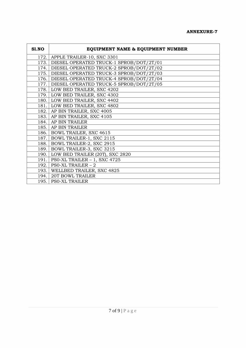
ANNEXURE-7
7 of 9 | P a g e
Sl.NO EQUIPMENT NAME & EQUIPMENT NUMBER
172. APPLE TRAILER-10, SXC 3301 173. DIESEL OPERATED TRUCK-1 SPROB/DOT/2T/01 174. DIESEL OPERATED TRUCK-2 SPROB/DOT/2T/02 175. DIESEL OPERATED TRUCK-3 SPROB/DOT/2T/03 176. DIESEL OPERATED TRUCK-4 SPROB/DOT/2T/04 177. DIESEL OPERATED TRUCK-5 SPROB/DOT/2T/05 178. LOW BED TRAILER, SXC 4202 179. LOW BED TRAILER, SXC 4302 180. LOW BED TRAILER, SXC 4402 181. LOW BED TRAILER, SXC 4802 182. AP BIN TRAILER, SXC 4005 183. AP BIN TRAILER, SXC 4105 184. AP BIN TRAILER 185. AP BIN TRAILER 186. BOWL TRAILER, SXC 4615 187. BOWL TRAILER-1, SXC 2115 188. BOWL TRAILER-2, SXC 2915 189. BOWL TRAILER-3, SXC 3215 190. LOW BED TRAILER (20T), SXC 2820 191. PS0-XL TRAILER – 1, SXC 4725 192. PS0-XL TRAILER – 2 193. WELLBED TRAILER, SXC 4825 194. 20T BOWL TRAILER 195. PS0-XL TRAILER

ANNEXURE – 8 COMPLIANCE STATEMENT

Annexure-8
CONFIRMATION / COMPLIANCE STATEMENT
Sl No
Description of terms and conditions
Compliance Reasons for deviation
Yes No
If No, explain the reason (if space is not sufficient separate sheet may be
enclosed)
1 SCOPE OF WORK: Operation / Driving, Maintenance, Painting and Load testing of equipment once in a year, attending to Minor & Major breakdown maintenance & Operational support as per the points 1.1 to 1.3 of tender document (Annexure-1).
2 Acceptance for carrying out all the works mentioned in the tender document (Annexure-1) as per point 1.4
3 Work Stations: Number of Work Stations, Place of work & its location as per the point 2.1 to 2.3 of tender document (Annexure-1).
4 Operation / Driving works: List of vehicles / equipment to be operated in and around SDSC SHAR, Sriharikota in general & outside as and when required & as per the points 3.1 to 3.4.7 of tender document (Annexure-1).
5 Equipment to be Maintained: List of vehicles / equipment to be maintained, type of Maintenance as per Annexure 3, 4, 5 & 6 as per points 4.1 to 4.4 of tender document (Annexure-1).
6 Periodic maintenance schedule book for each equipment / vehicle as per the Annexure 4 & 5 as per points 4.5 of tender document (Annexure-1).
7 Submission of rates for scheduled periodic maintenance of equipment / vehicle listed in the Annexure-2 as per point 4.6 of tender document (Annexure-1).
8 Tyre & Wheel Change as per point 4.7.1 of tender document (Annexure-1).
9 Quotation of rate for Replacement / re-fitment of ages tyres as per point 4.7.2 of tender document (Annexure-1).
10 Tyres and tubes will be supplied by Department as per point 4.7.3 of tender document (Annexure-1).
11 Essential expertise of Maintenance staff as per point 4.8 of tender document (Annexure-1).
12 Addition or deletion of equipment / vehicles during the contract period as per point 4.9 of tender document (Annexure-1).
13 Arranging additional manpower for completion of maintenance of vehicles / equipment with no extra payment as per point 4.10 of tender document (Annexure-1).
14 Load Testing: Acceptance for load testing of Equipment / Vehicles after annual maintenance as per the terms mentioned in the point 4.11.1 to 4.11.3 of tender document (Annexure-1)
15 Acceptance for Load testing of equipment as per point 4.11.4 of tender document (Annexure-1)
16 Working Hours: General working timings, public holidays as per points 5.1 to 5.2 of tender document (Annexure-1).
17 Working on public holidays, beyond normal working hours on working days as and when work demands as per points 5.3 to 5.4 of tender document (Annexure-1).

Annexure-8
CONFIRMATION / COMPLIANCE STATEMENT
Sl No
Description of terms and conditions
Compliance Reasons for deviation
Yes No
If No, explain the reason (if space is not sufficient separate sheet may be
enclosed)
18 Duration of Contract: Period of contract will be Two years as per Point 6.1 of tender document (Annexure-1).
19 Acceptance of contract for 3rd year as per the point 6.2 of tender document (Annexure-1).
20 Department’s right to terminate contract at any time as per the point 6.3 of tender document (Annexure-1).
21 Manpower requirement: Qualification and experience of Contractor’s staff as per point 7.1 to 7.3 of tender document (Annexure-1).
22 Minimum work force and penalty for absenteeism as per point 7.4 of tender document (Annexure-1).
23 Work Routines: Scrutinize of Maintenance schedules, responsibility of filling up schedules check lists in prescribed format as per 8.1 to 8.3 of tender document (Annexure-1).
24 Attending to Minor breakdown maintenance to vehicles / equipment with no extra cost as per 9.1 of tender document (Annexure-1).
25 Major breakdown maintenance: Acceptance of providing additional manpower for attending to major breakdown maintenance as per Point 9.2.1 of tender document (Annexure-1).
26 Acceptance of attending to Major Breakdown maintenance in side & outside SDSC SHAR & Machining works as per Point 9.2.2, 9.2.3 & 9.2.4 respectively of tender document (Annexure-1).
27 Acceptance for providing additional manpower for operational support works as per points 9.3.1 to 9.3.4 of tender document (Annexure-1).
28 Acceptance for Painting of Equipment as per the point 10.1 to 10.9 of tender document (Annexure-1).
29 Acceptance for bringing set of Tools and minimum quantity of consumable as per the point 11.1 to 11.3 of tender document (Annexure-1).
30 Spare parts / Lubricants: Procurement of spare parts, lubricants & components as per points 12.1 to 12.4 of tender document (Annexure-1).
31 Transportation & Accommodation: Transportation and accommodation arrangements for contractor’s staff as per points 13.1 to 13.2 of tender document (Annexure-1).
32 Entry Pass arrangement: Furnishing authentic proof of his staff and Acceptance of points 14.1 to 14.3 of tender document (Annexure-1).
33 Payment of Bills: Acceptance of Payment terms, Income tax deductions as per the points 15.1 to 15.3 of tender document (Annexure-1).
34 Acceptance of terms as per point 15.4 of tender document (Annexure-1)
35 Penalty clause: Acceptance of penalty as per the points 16.1 to 16.2 of tender document (Annexure-1).

Annexure-8
CONFIRMATION / COMPLIANCE STATEMENT
Sl No
Description of terms and conditions
Compliance Reasons for deviation
Yes No
If No, explain the reason (if space is not sufficient separate sheet may be
enclosed)
36 Contractor’s Site visit as per the Point 17.1 of tender document (Annexure-1).
37 Acceptance of offer validity period of SIX months as per
the point 17.2 of tender document (Annexure-1).
38 Acceptance for issue of individual letter of appointments to contractor’s staff as per point 17.3 of tender document (Annexure-1).
39 Acceptance of disbursement of monthly salaries through Nationalized Bank as per the point 17.4 of tender document (Annexure-1).
40 Acceptance for ensuring contract staff wearing safety gadgets as per points 17.5 to 17.8 as per tender document (Annexure-1).
41 Acceptance of Insurance of Contractor and his staff as per point 17.9 of tender document (Annexure-1).
42 Acceptance for submitting proof of EPF remittance as per point 17.10 of tender document (Annexure-1).
43 Acceptance for point 17.11 as per tender document (Annexure-1).
44 Acceptance for no liability of department as per point 17.12 to 17.13 as per tender document (Annexure-1).
45 Acceptance for responsibility of violation of security provisions as per point 17.14 of tender document (Annexure-1).
46 Acceptance for point 17.15 as per tender document (Annexure-1).
47 Acceptance for mobilization of contractor’s team within 15 days from the date of receipt of firm purchase order as per point 17.16 of tender document (Annexure-1).
48 Acceptance for disbursement of salaries to Contractor’s staff on or before 7th of every succeeding month as per 17.17 of tender document (Annexure-1).
49 Acceptance for ensuring various acts and amendments as per point 17.18 of tender document (Annexure-1).
50 Acceptance for maintaining records and documents as per labour laws as per point 17.19 of tender document (Annexure-1).
51 Acceptance to ensure minimum wages and leaves for contract staff as per points 17.20 to 17.22 as per tender document (Annexure-1).
52 Acceptance for department’s rights to withhold the bills as per point 17.23 of tender document (Annexure-1).
53 Age limit: Acceptance for deploying manpower as per the age restrictions mentioned in the point 17.24.1 to 17.24.2 of tender document (Annexure-1).
54 Taxes & Duties: Acceptance of terms as per 17.25.1 to 17.25.2 of tender document (Annexure-1)
55 Security Deposit: Acceptance of security deposit terms as per the point 18.1 of tender document (Annexure-1).
56 Price Variation Per Year : Submission of price variation per year, Quotation format- 8 as per point 19 of tender document (Annexure-1).

Annexure-8
CONFIRMATION / COMPLIANCE STATEMENT
Sl No
Description of terms and conditions
Compliance Reasons for deviation
Yes No
If No, explain the reason (if space is not sufficient separate sheet may be
enclosed)
57 Arbitration: Acceptance of Arbitration terms as per point 20 of tender document (Annexure-1).
58 Earnest Money Deposit (EMD): Acceptance of EMD terms as per the point 21.1 to 21.6 of tender document (Annexure-1).
59 Submission of Confirmation / Compliance statement along with Techno Commercial bid (part-1) as per the point 22.2.1 of tender document. (Annexure-1).
60 Submission of Quotation Format-1, 2, 3, 4 & 5 along with Price bid (part-2) as per the point 22.2.2 of tender document (Annexure-1).
61 Acceptance of receipt of Annexure-1, 2, 3, 4, 5, 6 & 7
62 Work Experience: Minimum five years of Work Experience & terms as per point 23.1 (a) of tender document (Annexure-1)
63 Annual Turnover: Annual Turnover of minimum 75 lakh and terms as per 23.1 (b) of tender document (Annexure-1).
64 Acceptance of terms as per point 23.1 (c) to 23.1 (d) of tender document (Annexure-1)


