
Antenna Theory fundamentals
Rafael Medina Sanchez
Assistant ProfessorAssistant Professor
University of Puerto Rico Mayaguez
Radio Frequency Spectrum Management WorkshopMayaguez, PR
May 25, 2016

Outline
• Antenna Fundamental
• Antenna Types
• Rules, Regulations, and Recommendations for
Antenna PatternsAntenna Patterns
May 25 2
Antenna FundamentalsAntenna Fundamentals
May 25 3

Antenna Definition
• “A means for radiating or receiving radio waves” (IEEE Std 145–
1983)
Transmitter Receiver
Antenna Antenna
• An antenna is a passive structure that provides a transitionbetween a guided wave (in a transmission line or waveguide) anda propagating wave (usually in free-space), and focuses theelectromagnetic energy into particular direction
May 25 4

Radiation
Two dimensional
representation of the
electric field radiated by a
wire antenna
The fields are the result of
solving the Maxwell
May 25 5
∫−
= '4
dlR
IeA
kR
πµ
µA
H A
×∇=
).( Aw
jjwAEA ∇∇−−=
εµ
solving the Maxwell
equations
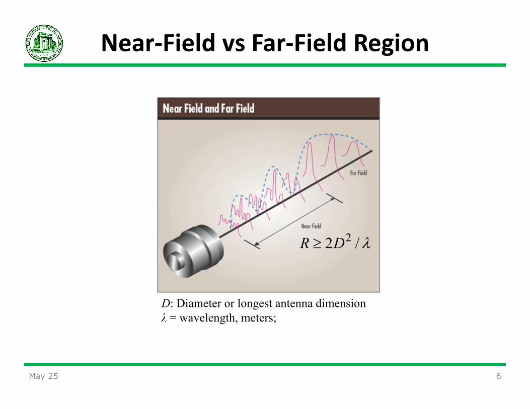
Near-Field vs Far-Field Region
May 25 6
λ/2 2DR ≥
D: Diameter or longest antenna dimension
λ = wavelength, meters;

Types of Antennas
• An isotropic antenna is a fictitious antenna that radiate the power
equally in all directions
• A directional antenna is a source of electromagnetic wave which
transmits or receives more power in some directions than others
• An omnidirectional antenna is an directional antenna that can provide
uniform radiation in a reference plane
May 25 7
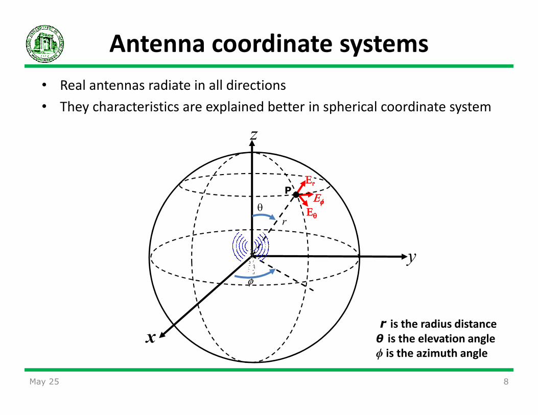
• Real antennas radiate in all directions
• They characteristics are explained better in spherical coordinate system
Antenna coordinate systems
z
θ ΕΕΕΕΕΕΕΕφφφφ
ΕΕΕΕr
P
May 25 8
x
y
θ
φ
ΕΕΕΕθθθθ
r is the radius distance
θ is the elevation angle
ϕ is the azimuth angle
r

Communication Link
• The signal power received by a radio system in the at point P is given
by
( )22
4
),(),(),,(
r
PLGGrP
tprrrtttr
π
λφθφθφθ =
Pr: received power, watts;
Gt(θt,ϕt) : transmitting antenna power gain;
Gr(θr,ϕr) : receiving antenna power gain;
• The received power not only depend on the system characteristics, but
also of the direction of the antenna observation point
9
Gr(θr,ϕr) : receiving antenna power gain;
λ = wavelength, meters;
Lp: propagation loss
Pt: transmitter power, watts;
r = range, meters

Radiation Pattern
• The radiation pattern is a graphical representation of the geometrical
distribution of the radiated power over all space
θ
Field
Strength
360°
May 25 10
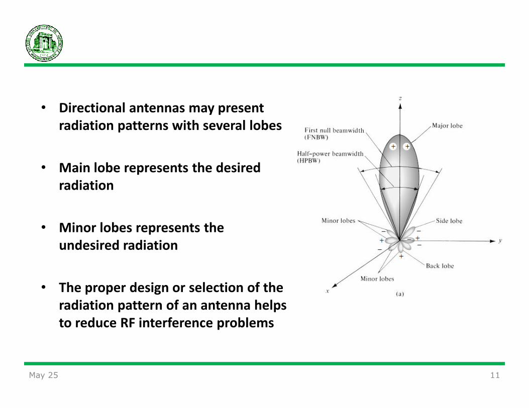
• Directional antennas may present
radiation patterns with several lobes
• Main lobe represents the desired
radiation
• Minor lobes represents the
undesired radiation
• The proper design or selection of the
radiation pattern of an antenna helps
to reduce RF interference problems
May 25 11
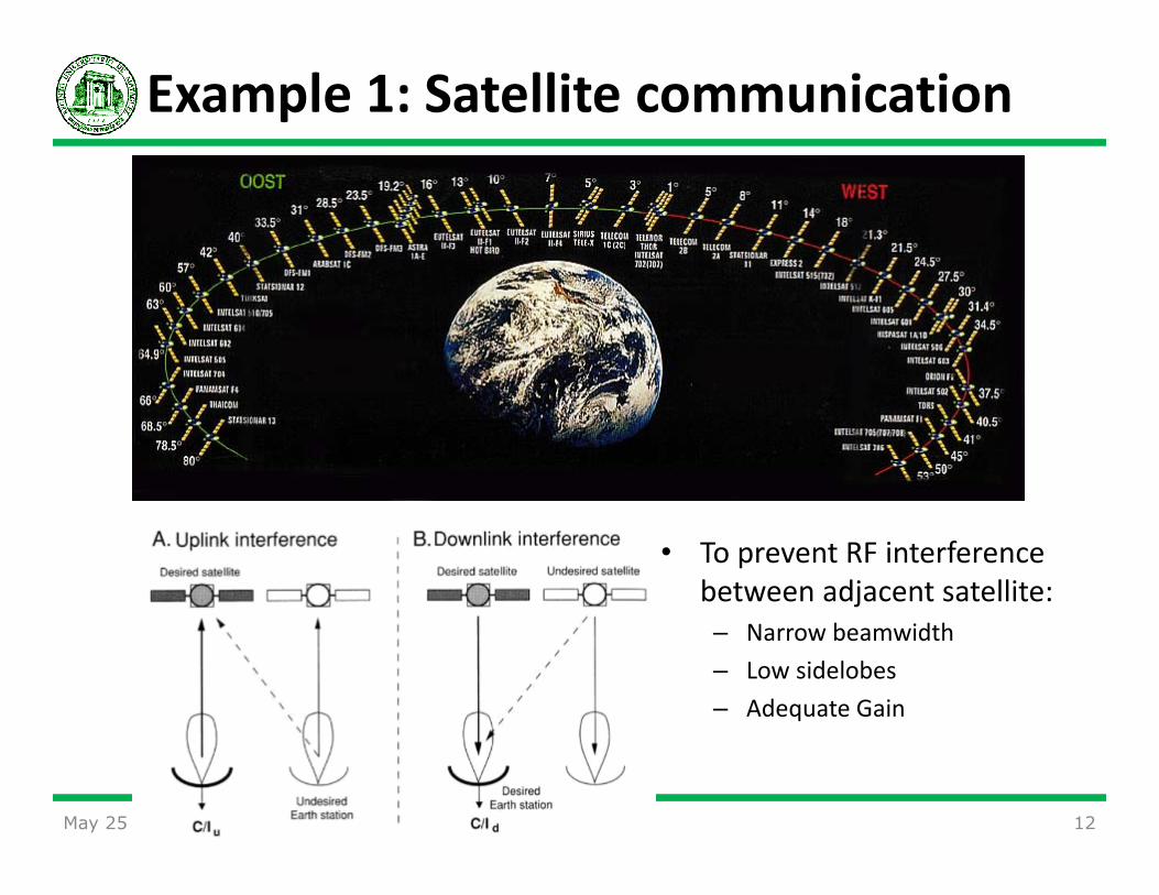
Example 1: Satellite communication
May 25 12
• To prevent RF interference
between adjacent satellite:
– Narrow beamwidth
– Low sidelobes
– Adequate Gain
May 25 13

Example 2: Meteorological Radar
May 25 14

Power
• The available power, P , is the total power supplied by the transmitter
Pant
Radiation
efficiency
Prad
Pavailable
Preflected
Antenna
=Prad
• The available power, Pavailable, is the total power supplied by the transmitter
• The antenna power, Pant, is the total power input to the antenna system. It
generates the far-field radiating EM wave, the non-radiating EM field that
stores energy in the near field, and joule heat.
• The far-field radiated power, Prad, is the total radiated power carried by the
far-field EM wave. Prad is independent of the propagation distance r and is a
constant.
15

Radiated Power Density
• The power density, Wrad, is the
product of the electric and magnetic
fields at a particular location (θ, ϕ)
in space.
• Wrad is given in watts/meters2
*Re2
1),( HEWrad ×=φθ
May 25 16
• We can be measured with power
meters
• When regulating radio interference
between radio systems, one of the
specifications is maximum allowable
Wrad
at the front end of a receiving
antenna
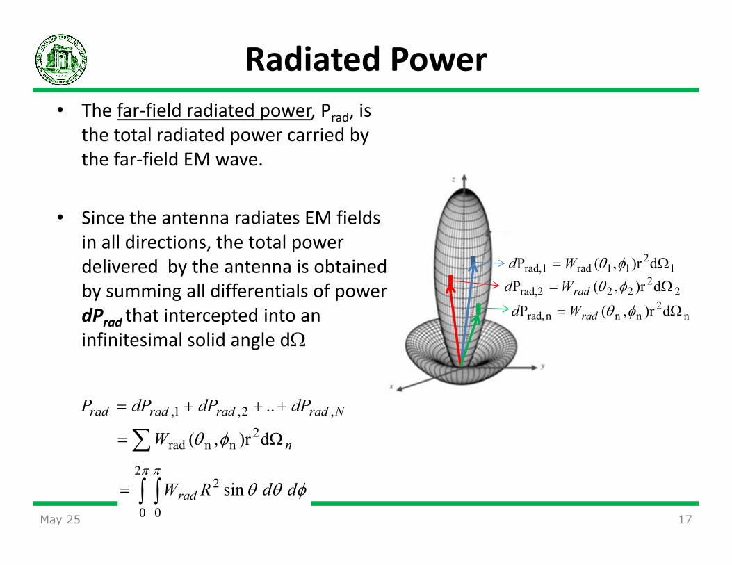
Radiated Power
• The far-field radiated power, Prad, is
the total radiated power carried by
the far-field EM wave.
• Since the antenna radiates EM fields
in all directions, the total power
delivered by the antenna is obtained
by summing all differentials of power
d)r,(P 12
11radrad,1 Ω= φθWd2d)r,(P Ω= φθWd
May 25 17
by summing all differentials of power
dPrad
that intercepted into an
infinitesimal solid angle dΩ
22
22rad,2 d)r,(P Ω= φθradWd
n2
nnnrad, d)r,(P Ω= φθradWd
∑ Ω=
+++=
n
Nradradradrad
W
dPdPdPP
d)r,(
..
2nnrad
,2,1,
φθ
∫ ∫=π π
φθθ2
0 0
2 sin ddRWrad

Directivity and Gain
• The directive gain of Directivity is given by
intensityradiation isotropic
intensity radiation DUT),( =φθD
18
intensityradiation isotropic
Gain
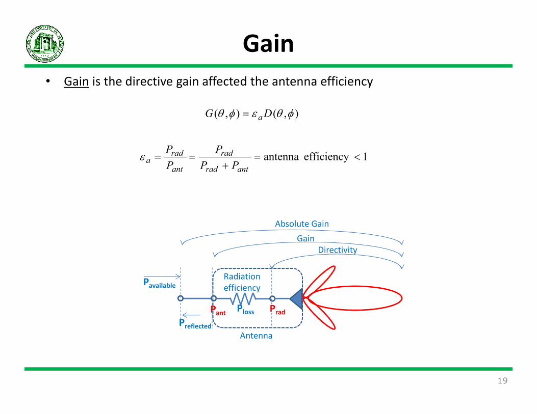
• Gain is the directive gain affected the antenna efficiency
),(),( φθεφθ DG a=
1efficiency antenna <=+
==antrad
rad
ant
rada
PP
P
P
Pε
19
Pant
Radiation
efficiency
Prad
Pavailable
Directivity
Gain
Absolute Gain
Preflected
Antenna
Ploss
• Usually, it is practical for antenna engineer expresses the directive and
gain in decibels
),(log10),( d10d φθφθ BB GG =
),(log10),( 10dB φθφθ DD =
May 25 20
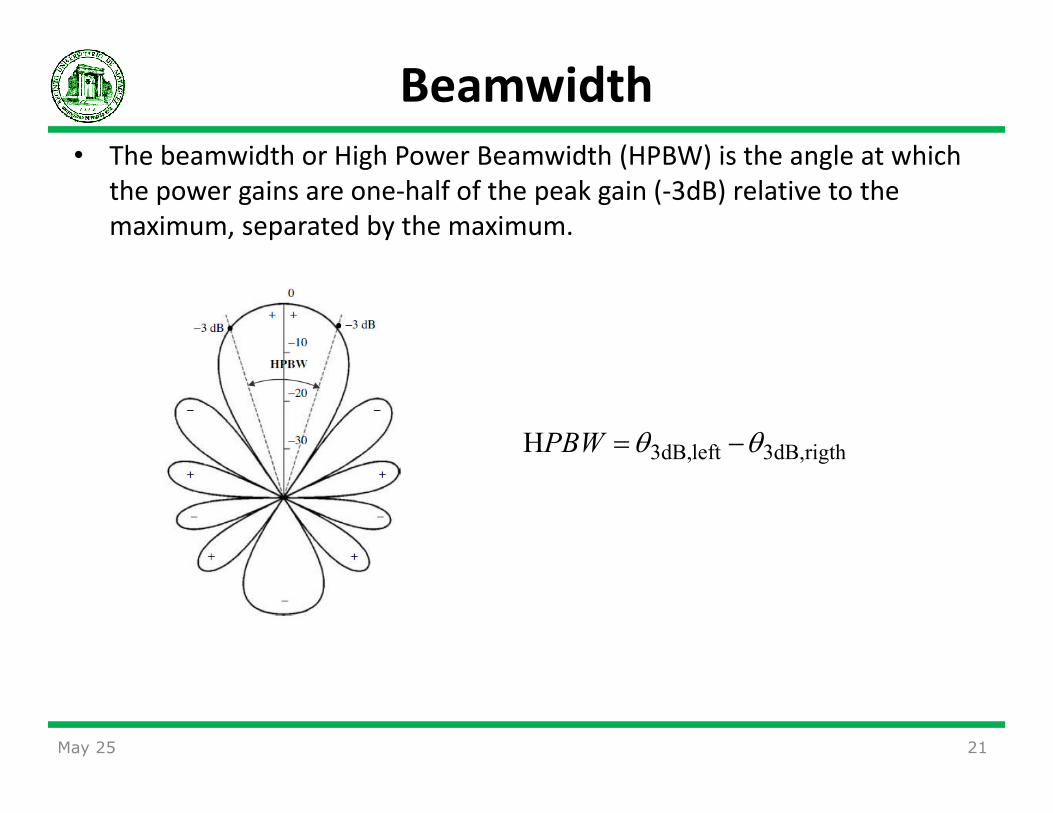
Beamwidth
• The beamwidth or High Power Beamwidth (HPBW) is the angle at which
the power gains are one-half of the peak gain (-3dB) relative to the
maximum, separated by the maximum.
rigth3dB,left3dB,H θθ −=PBW
21May 25
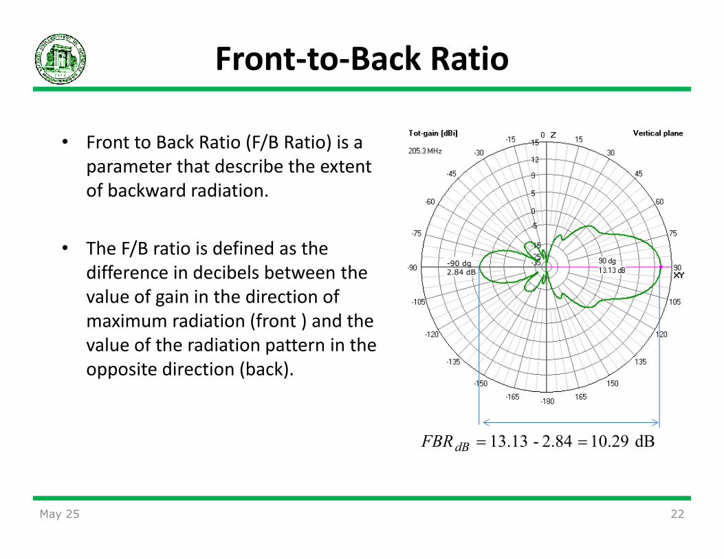
Front-to-Back Ratio
• Front to Back Ratio (F/B Ratio) is a
parameter that describe the extent
of backward radiation.
• The F/B ratio is defined as the
difference in decibels between the -90 dg2.84 dBdifference in decibels between the
value of gain in the direction of
maximum radiation (front ) and the
value of the radiation pattern in the
opposite direction (back).
May 25 22
dB 10.29 2.84-13.13 ==dBFBR

Sidelobe level
• Side Lobe Level (SLL) is a parameter used to describe the level of side
lobe suppression.
• High side lobes are often not desired
• The side lobe level is defined as the difference in decibels between the
main beam peak value and the side lobe peak value.
May 25 23
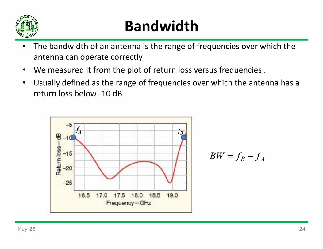
Bandwidth
• The bandwidth of an antenna is the range of frequencies over which the
antenna can operate correctly
• We measured it from the plot of return loss versus frequencies .
• Usually defined as the range of frequencies over which the antenna has a
return loss below -10 dB
24
AB ffBW −=
fA fB
May 25
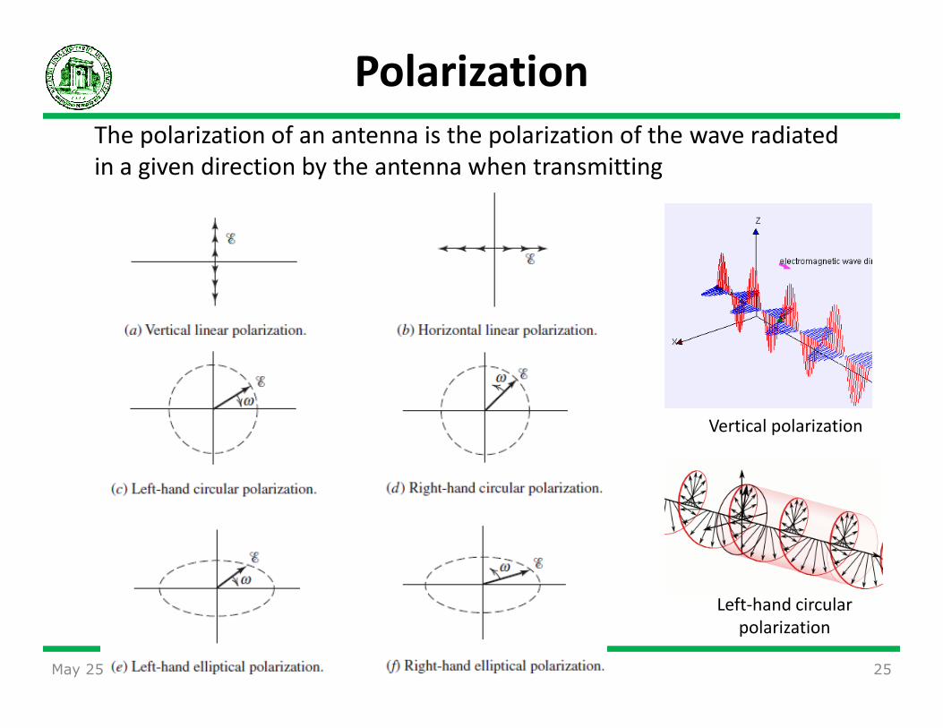
The polarization of an antenna is the polarization of the wave radiated
in a given direction by the antenna when transmitting
Polarization
May 25 25
Vertical polarization
Left-hand circular
polarization

Co-polarization and Cross-Polarization
• Most of the antennas are designed for one polarization, but the unavoidable
imperfection of the antenna design can cause the antenna to have cross-
polarization characteristics in its operations.
• When a radiation pattern is measured as the same polarization as the
antenna’s designated polarization, we called Co-Polarization pattern
• while its orthogonal pair, it called Cross-Polarization pattern
May 25 26

Ground Effect
May 25 27
Radiation pattern for an horizontal dipoles
placed at various height above a flat ground off
the ends of the antenna wire

Antenna TypesAntenna Types
May 25 28
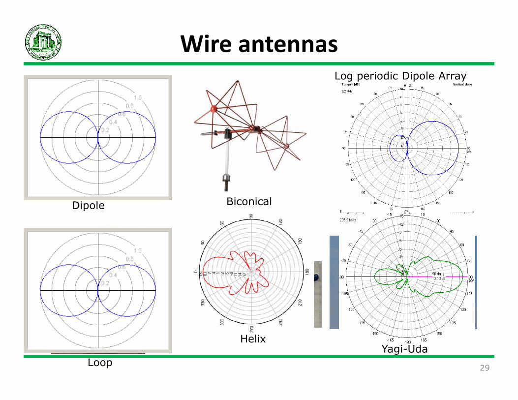
Wire antennasLog periodic Dipole Array
Dipole Biconical
Yagi-UdaHelix
Dipole
Loop29
Biconical

Aperture antennas
Open waveguide antennaHorn antenna Open waveguide antenna
Conical antenna
Horn antenna
30
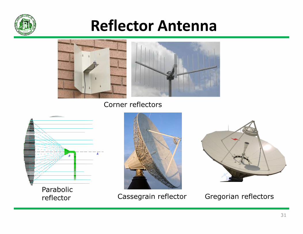
Reflector Antenna
Corner reflectors
Parabolic reflector
31
Cassegrain reflector Gregorian reflectors
32

Microstrip
PatchMicrostrip Patch Antenna in GPS Receiver Circuit Board
Log periodic
Dipole
Spiral
33
GPS Receiver Circuit Board
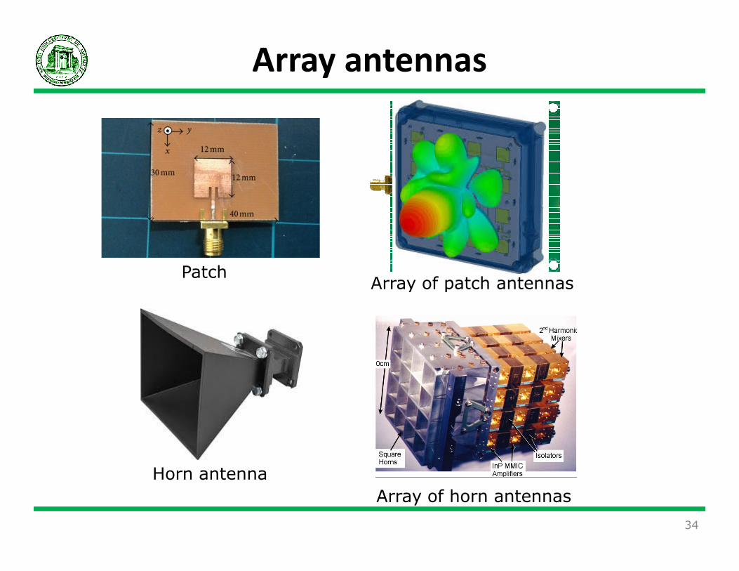
Array antennas
PatchArray of patch antennasArray of patch antennas
Array of horn antennas
34
Horn antenna

May 25 35
Phased array antennas
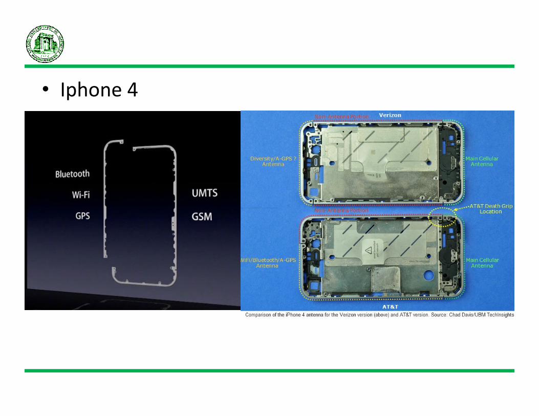
• Iphone 4

Rules, Regulations, and
Recommendations for Antenna Recommendations for Antenna
Patterns
May 25 37

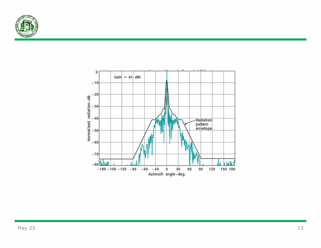
Reference Radiation Pattern
• Considering that there is a need to control the levels of interference which
may occur at difference radio services, due to various sources of
interference, a reference antenna pattern is typically defined
• A reference radiation pattern is the envelope of the actual radiation pattern,
and is usually artificially shaped to be symmetric to the mainbeam axis.
May 25 38
Antenna radiation performance standards
• Some sources for rules, regulations, and recommendations about
antennas are:
– NTIA Manual
– Title 47 of the Code of Federal Regulations (47 CFR) for FCC
– The ITU-R Radio Regulations (RR)
– The ITU-R Recommendations
• Antenna radiation performance standards and reference radiation
patterns are developed from measured radiation patterns,
• and then established as reference with consensus from radio spectrum
regulators and antenna engineers.
• Regulators use them as reference in EMC analyses,
• and engineers use them as compliance guidelines in antenna design
and production.
May 25 39
Categories of Radio Services
• Classes of radio services categorized by ITU-R
– Antenna data for the Fixed Service (FS),
– Fixed-Satellite Service (FSS),
– Broadcasting Service (BS),
– Broadcasting-Satellite Service (BSS), Mobile Service (MS),
– Mobile-Satellite Service (MSS),
– Radiodetermination Service (RDS),– Radiodetermination Service (RDS),
– Radiodetermination-Satellite Service (RDSS),
– Radio Astronomy Service (RAS),
– Remote Sensing Service (RSS),
– and Space Application Service (SA)
May 25 40

Example: Broadcasting-Satellite Service
• Consists of an uplink that feeds the program to the satellite for downlink broadcasting,
• and many receive-only earth stations to receive the program.
• Ground antennas:
17.3–17.8 GHz 12.2–12.7 GHz
• Ground antennas:
– Feeder Link Transmitting Antenna
– Downlink Receive-Only Antenna
• Satellite antenna
– Feeder Link Receiving Antenna
– Downlink Receive-Only Antenna
May 25 41
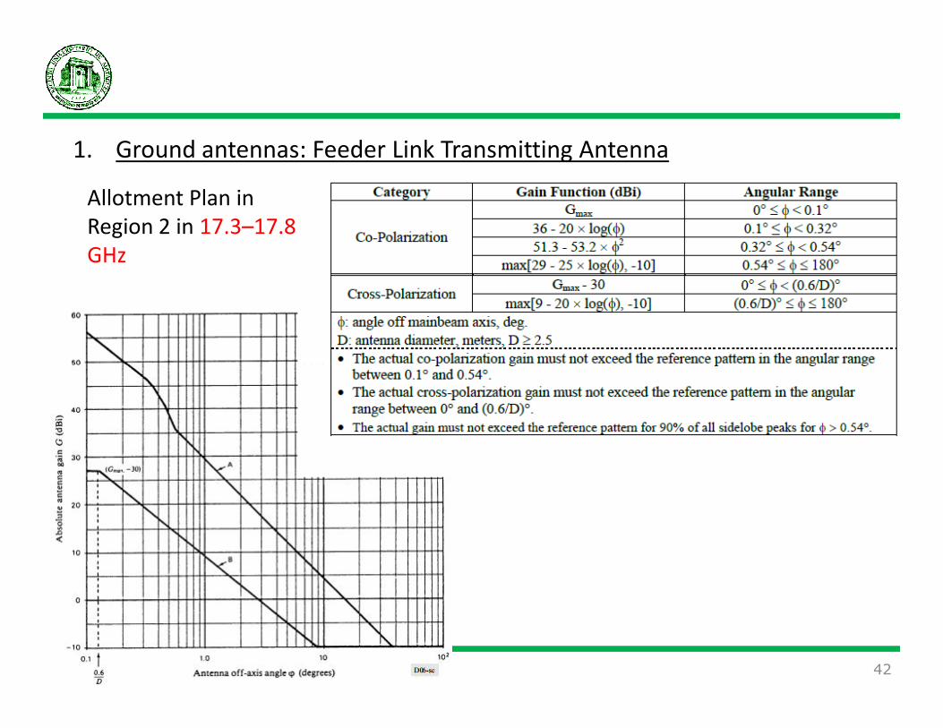
1. Ground antennas: Feeder Link Transmitting Antenna
Allotment Plan in
Region 2 in 17.3–17.8
GHz
May 25 42

4. Satellite antennas: Feeder Link Transmitting Antenna
Allotment Plan in
Region 2 in 17.3–17.8
GHz
May 25 43

2. Ground antennas: Downlink Receive-Only Antenna
Allotment Plan in
Region 2 in 12.2–12.7
GHz
May 25 44

May 25 45


