970-385 Revised 0513
MC SERIES
Table of ContentsUnit Features...........................................................................................................................1Design Features......................................................................................................................2Reverse Cycle Operation........................................................................................................5Economizer / Filter Bank Module............................................................................................5Blowers ...................................................................................................................................5Available Options ....................................................................................................................5Selection Procedure................................................................................................................7Specification Data Sheets.......................................................................................................9Physical Data Specifications.................................................................................................13Water-side Economizer Performance ...................................................................................14Correction Factors.................................................................................................................14Hot Water Coil Capacity........................................................................................................15Pressure Drop Tables ...........................................................................................................16Blower Performance..............................................................................................................17Drive Selection Table............................................................................................................18Shipping Weights ..................................................................................................................19Physical Dimensions.............................................................................................................20Electrical Specifications ........................................................................................................24Wiring Diagrams....................................................................................................................25Guide Specifications .............................................................................................................28
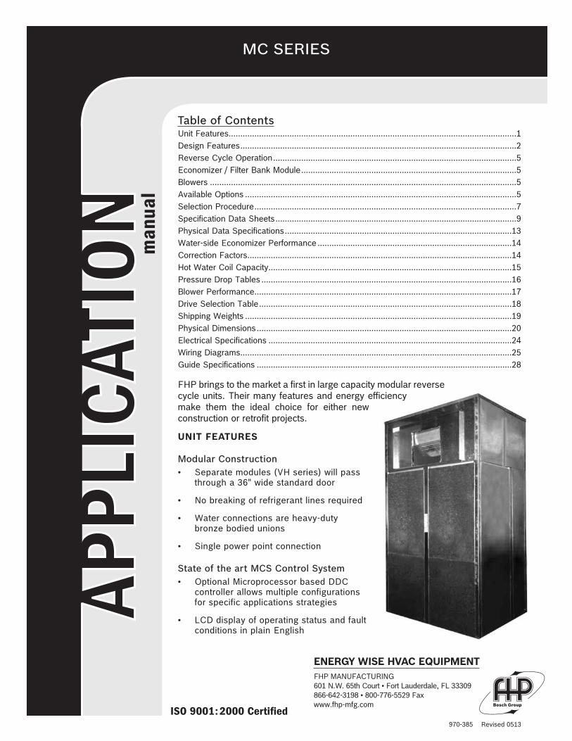
FHP brings to the market a first in large capacity modular reversecycle units. Their many features and energy efficiencymake them the ideal choice for either newconstruction or retrofit projects.
UNIT FEATURES
Modular Construction• Separate modules (VH series) will pass
through a 36" wide standard door
• No breaking of refrigerant lines required
• Water connections are heavy-dutybronze bodied unions
• Single power point connection
State of the art MCS Control System• Optional Microprocessor based DDC
controller allows multiple configurationsfor specific applications strategies
• LCD display of operating status and faultconditions in plain English
ENERGY WISE HVAC EQUIPMENTFHP MANUFACTURING601 N.W. 65th Court • Fort Lauderdale, FL 33309866-642-3198 • 800-776-5529 Faxwww.fhp-mfg.com

970-385 Revised 0513
REVERSE CYCLE HEAT PUMP OPERATION• Optional reverse cycle heating
• Takes full advantage of building diversity
ENERGY EFFICIENCY
• High efficiency in the cooling mode
• Economical operation in heating with reverse cycleoperation
• Economizer operation reduces compressoroperating hours increases system efficiency
• Individual units can be monitored for actualelectrical usage by tenants
VARIABLE AIR VOLUME CAPABILITY
• Units can be fitted with VFD for additional energysavings
• Increased operational flexibility
QUIET OPERATION
• Scroll compressors for efficient quiet operation
• Heavy duty structural components
• Multi density coated glass fiber insulation
RELIABILITY
• Units are fully assembled and tested at the factoryto ensure smooth assembly and start up in the field
• No reliance on central plant equipment for buildingclimate control
• Multiple refrigerant circuits provide redundancy inthe event of component failure
100% OUTSIDE AIR CAPABILITY
• Hot gas reheat for humidity control
HOT GAS BYPASS
• Allows operation under a wide variety of conditions
• Provides protection against coil freezing
DESIGN FEATURES:
UNIT CONSTRUCTION
The FHP MC series is available in two basic configurations:
VH CONFIGURATION
The VH design concept is to provide a unit that willfacilitate on site handling and can be installed in locationsdifficult to access. All units can be broken down intoseparate modules that can pass through a 36" widestandard door or service elevator. No refrigerant pipingrequires disconnection, maintaining circuit integrity. Water
piping connections are made with the use of heavy-dutybronze-bodied unions so no welding or brazing is requiredin the field. Single supply and return connection to the unitare standard. This creative design allows the installer totransport and locate the modules in the equipment roomwithout the use of heavy-duty cranes or lifts. Buildingpenetrations or interior wall penetrations are not normallyrequired on retrofit jobs where space is at a premium. The30 ton module can be easily broken down into 3 separatemodules - the fan module, main heating/cooling moduleand the economizer/filter bank. The 40 through 60 tonunits can be broken into 6 separate modules, two each aspreviously mentioned. Very few competitive equipmentmanufacturers have this capability.
VL CONFIGURATION
The VL is designed for those applications where there isa restriction in the height of the unit. In this model theblower is dropped into the main coil section reducing theunits overall height and increasing unit depth. Unit sizesMC480 through MC720 can be split into two sections fortransportation and access into the plant room.
Please see unit drawings on pages 20 through 23 forunit dimensions.
FLEXIBILITY
The FHP MC series is available in cooling only or withreverse cycle heating with either constant or variable airvolume discharge to provide a highly efficient operatingsystem. Water-side economizer packages are availableto take advantage of free cooling. Optional fieldinstalled hot water coils provide preheating or heating.Hot gas bypass allows the unit to operate under a widevariation of conditions and the hot gas reheat optionprovides a means of controlling humidity, a majorconcern in the interior environment of a building.
2
VH Configuration
MC SERIES

970-385 Revised 0513
UNIT PERFORMANCE
The units are available in four sizes from nominal 30through 60 tons.
Performance is with nominal CFM and rated in accordancewith ARI/ISO 13256-1 conditions. Performance numbersare gross.
CABINET, CASING AND FRAME
For heavy-duty structural support an internal angle ironframework is utilized. The angle iron members are attachedusing 1/2 inch bolts and locking nuts for ease ofdisassembly and reassembly. The base-pan assembly isconstructed of 14 gauge galvanized steel. Exterior panelsare made of 18 gauge, G90 galvanized steel providingprotection against corrosion. All panels are insulated with1/2 inch thick dual density Neoprene backed fiberglassinsulation for thermal and acoustic performance. Insulationmeets the erosion requirements of UL 181. Base rails areprovided to assist rigging the unit on site. All componentsare located for ease of inspection and service. Majorcomponents are out of the units air stream to allowmaintenance while the unit is in operation. Service accessis through the removal of access panels located on the unit.
COMPRESSORS
All units utilize high efficiency scroll compressors. TheMC360 has two compressors while the MC480 throughMC720 units contain four compressors for efficient partload control, quiet operation and system redundancy.
Each compressor has its own independent refrigerantcircuit and is protected by individual branch fusing.Additional protection is providedby thermal overloads and highand low pressure safety switches.Suction and discharge schradervalves are provided for manifoldgauge connections to facilitateservicing. Compressors aremounted on vibration isolators.
The entire condensing section isisolated from the air-handlingcompartment by the use of aninsulated bulkhead partitiondesigned to minimize soundtransmission.
Externally equalized balancedport thermostatic expansionvalves are utilized for wide rangerefrigerant metering control.Superheat shifts are minimal from
cooling to heating operation ensuring stable operation inboth the heating and cooling modes. All TXV’s are factoryset and are field adjustable for specific operating conditions.Reversing valves are large bodied to minimize refrigerantpressure drop. All refrigerant components are accessiblefrom the front of the unit for service and maintenance.
CONDENSERS (water to refrigerant heat exchangers)
All condensers are coaxial tube-in-tube for maximumheat transfer efficiency and performance. Inner watertubes are either copper or optional cupro-nickel withlarge internal diameters for reduced water-side pressuredrops. Outer tubes are steel, painted for corrosionprotection. All condensers are rated at 450 PSIGoperating refrigerant pressures and 400 PSIG water-sidepressures. Condensers are individually leak tested. Allcondensers are chemically cleanable. Please consult thefactory for cleaning procedures. Units are designed forsingle water supply/return connections with modulesbeing connected by the use of heavy-duty bronze unions.
DX COOLING/HEATING COIL
Evaporators are enhanced fin, rifled tube type for maximumperformance. Large face areas ensure low airside pressuredrops and reduced face velocities to prevent condensatecarry over and maximum moisture removal.
Coils are either three or four rows deep depending onunit model and mounted in small area, sealed drain pansto inhibit condensate buildup levels.
All drain pans are galvanized steel with Archem typecoating for corrosion protection. Optional stainless steeldrain pans are available. Bottom outlet fittings in drainpans ensure free draining. Optional condensate overflowswitches are available.
Each refrigerant circuit is independently piped allowingpart load operation in the event of a component failure.Compressor/evaporator staging is such that airstratification is kept to a minimum. The lowerevaporators on each module are staged first to keepcoils wet and enhance condensate removal. In the eventof an evaporator failure only the individual coil need bechanged compared to the full face evaporators utilizedby some manufacturers.
ELECTRICAL
All units are completely wired and tested at the factoryprior to shipment. Wiring complies with NECrequirements and units are UL 1995 safety certified andlisted. Single point power supply is standard on allmodels. Each module has its own power blocksimplifying wiring in the field for knock down capabilities.Supply air fan motors are protected by use of a solidstate adjustable current motor starter with reset.
Extra starter heaters are not required. All compressorpower circuits are branch fuse protected. Control circuitpower is provided by a factory mounted 100 VA lowvoltage transformer with an integral resettable circuitbreaker. Solenoid valves are line voltage to reducetransformer loading.
3
Unit Size CFM RangeCooling Capacity
TonsEER
Heating CapacityMBH
COP
MC360 6,000 - 12,400 32.6 18.6 386.9 5.5
MC480 8,000 - 19,200 41.7 19.0 623.3 5.4
MC600 10,000 - 24,000 53.1 19.0 731.8 5.4
MC720 12,000 - 24,800 65.3 18.6 773.9 5.5
MC SERIES

970-385 Revised 0513
SAFETY DEVICES AND THE UPM CONTROLLER
Each MC unit is factory provided with a Unit ProtectionModule (UPM) that controls compressor operation andmonitors the safety controls that protect the unit. Unitsizes 480-720 will have a board in each section.
Safety controls include the following:
• High pressure switches located in the refrigerantdischarge lines. One per refrigeration circuit.
• Low pressure switches for loss of charge protectionlocated in the unit refrigerant suction lines. One perrefrigeration circuit.
• Optional freeze protection sensor located on theleaving side of the water coil prevents unit operationbelow 35ºF. A freeze stat pin located on the boardmay be put in the YES or NO position dependingwhether the freeze stat is ordered
NOTE: The factory default is in the YES position. If thefreeze stat option is not ordered the pin must berelocated to the NO position.
• Optional Condensate overflow protection sensorlocated in the drain pan(s) of the unit and wired tothe UPM board.
The UPM includes the following features:
• ANTI-SHORT CYCLE TIMER – 5 minute delay onbreak timer to prevent compressor short cycling.
• RANDOM START – Each controller has a uniquerandom start delay ranging between 270 through 330seconds.
• LOW PRESSURE BYPASS TIMER - The lowpressure switch is bypassed for 120 seconds aftercompressor start-up to prevent nuisance lowpressure lockouts during cold start-up in the heatingmode.
• B R O W N O U T / S U R G E / P O W E RINTERRUPTION PROTECTION – a 20millisecond window is monitored for the abovecondition. Should any of these conditions bedetected, the 5-minute delay on break timer and therandom start timer delay are initiated.
• MALFUNCTION OUTPUT – The controller has aset of wet contacts for remote fault indication.
• TEST SERVICE PIN – A jumper pin is provided toreduce all time delay settings to 5 seconds duringtroubleshooting or verification of unit operation. Notethat operation of the unit in test mode can lead toaccelerated wear and premature failure of the unit.
• L.E.D. FAULT INDICATION – Two L.E.D.indicators are provided as follows:
• GREEN: Power L.E.D. indicates 18 – 30 VACpresent at the board.
• RED: Fault indicator with blink codes as follows:
One per Dual Circuits (UPM-II)
• ONE BLINK 1st Stage high pressure lockout
• TWO BLINKS 1st Stage low pressure lockout
• THREE BLINKS2nd Stage high pressure lockout
• FOUR BLINKS 2nd Stage low pressure lockout
• FIVE BLINKS Freeze Protection lockout
• SIX BLINKS Condensate overflow lockout
• INTELLIGENT RESET - If a fault condition isinitiated the 5 minute delay on break time period isinitiated and the unit will restart after this delayexpires. If the fault condition still exists or reoccurswithin one hour, the unit will go into a hard lockoutand require a manual lockout reset.
• LOCKOUT RESET - A hard lockout can be reset byturning the unit thermostat off and then back on or byshutting off unit power at the circuit breaker.
NOTE: The blower motor will remain active during alockout condition.
MCS (MODULAR CONTROL SYSTEMSDDC CONTROLLER)
OPTIONAL MCS DDC CONTROLLER
An optional MCS DDC controller is available on the MCseries. This controller can act as a stand-alone controlleror interface with a building management system or beconnected to a PC. Remote dial in capability through anoptional modem is also available. The MCS has thecapability to interface with BACNET communicationprotocol through an optional portal.
The controller is capable of monitoring and controllingtemperatures, static pressure (VAV applications),humidity, fluid flow and airflow as required and whenordered with the appropriate sensors.
The standard unit controller is configured for constantvolume, return air control. Optional control strategies are
4 MC SERIES

available, for example, humidity/reheat control andvariable air volume discharge air temperature control withreturn air reset. All safety inputs are monitored and alarmsignals can be generated. The controller willautomatically restart the machine following a non-criticalalarm condition, not taking the unit off line unless thesame alarm has occurred twice within an adjustable timeperiod. Nuisance shut down of the unit is avoided whilestill providing protection against possible equipmentfailure. A record of faults and time of occurrence is keptin the controller to facilitate trouble shooting and servicingof the unit. A systems time clock is standard on all MCScontrollers enabling programming for daily operations.
All necessary sensors are factory provided, field installedfor application specific control strategy. The controller isconveniently located on the unit for easy reading andprogramming. A 2 line 16 character LCD displays alltemperature, pressure and control functions in easy to readEnglish. Battery back up is standard to prevent loss ofoperating parameters during power interruptions/losses. Afour layered printed circuit board protects themicroprocessor from power surges or fast transientsacross or over the lines. Please refer to the unit controllermanual for further details
REVERSE CYCLE OPERATION
All MC series units are capable of operating in the reversecycle heat pump mode for efficient, cost effective heating.The MC series is the only self-contained heat pump unit inits class. This feature allows the designer to take fulladvantage of building diversity, transferring excess heatfrom areas with a net cooling load to areas requiringheating providing a truly energy efficient system.
HOT WATER COIL
An optional one or two row hot water coil is available forhydronic heating. The coil is available either installed inthe filter section (if the economizer option is not ordered)or for external mounting. In both cases piping, valvesand controls are by others.
ECONOMIZER/FILTER BANK MODULE
Factory installed water-side economizer coils are availableon all MC series units. The economizer package consistsof full-face area multi-row copper tube, aluminum fin coilsdesigned for low water-side pressure drops. A 3-waymotorized ball valve is included in the package for waterflow control. The valve includes a manual clutch option forfield over-ride capability while an optional minimumpositioner for the valve is also available. The economizermay be controlled through the optional controller whichsenses entering fluid temperature to the unit and opens thevalve to allow flow through the economizer coil andcondenser in series. In normal operation, flow is throughthe condenser only. The set point is adjustable between 45degrees and 70 degrees in the cooling mode. A heatingeconomizer cycle is also available utilizing hightemperature loop fluid or high temperature fluid from a heatexchanger that is on a hot water hydronic loop. Thepackage has a 400 PSIG design working pressure and ispressure tested for leaks at the factory.
FILTERS
All MC series units come with standard 4 inch 30%efficiency pleated filters. Optional 65% 4 inch pleatedfilters are available. Filters are removable from the sidesof the frames through filter access panels. Throw awayconstruction filters should be field installed to protect themain filters during the construction period.
BLOWERS
The units contain either one or two forward curved high-pressure class II fan assemblies depending on the modelsize. The fans are double width, double inlet weldedassemblies statically and dynamically balanced. In the VHSeries, the fan module is isolated from the main moduleby the use of rubertex gaskets providing excellentvibration isolation and quiet operation. The modules arebolted together with 1/2 inch diameter bolts and lockingnuts. Each fan is powered by it’s own motor and driveassembly. Motors are mounted on individual motorplatforms for stable operation and belt tension adjustment.All assemblies include 150,000-hour re-greaseable pillowblock bearings with large diameter solid steel shafts forhigh torque/speed operation. Drive packages comprisemultiple belt, fixed pitch blower pulleys and motor sheavessized for specific application requirements of CFM,external static pressures, and motor horsepower. Allcomponents are easily accessible for generalmaintenance. Motors are open drip proof NEMA T-FrameE high efficiency EPACT rated with sealed ball bearings.
Optional factory installed variable frequency drives areavailable for variable air volume systems. The drives arelocated in the fan section and may be controlled by theoptional DDC. A static pressure sensor is field installed in thesupply duct plenum dictating motor speed based on anincrease or decrease in the supply duct static pressure. VFD’sare factory programmed per job specific design criteria.
5MC SERIES
Revised 0513

970-385 Revised 0513
All drives are NEMA 4/12 enclosed with an integralkeypad for program adjustments. Removable accesspanels allow drive adjustments during motor operation.Constant power line reactors are also furnished witheach drive for power supply filtration.
AVAILABLE OPTIONS
• Proof of fluid flow - factory installed differentialpressure switch
• Entering/leaving fluid temperature sensors.
• Factory installed freeze protection sensor.
• Control algorithm options - space/return air control,discharge air with space/return air reset control,VAV control. Only available with optional DDC.
• Water-side economizer.
• Hot gas reheat on constant volume units with orwithout 100% outside air introduction - factoryinstalled with controls for dehumidificationapplications when equipped with optional DDC.
• Hot water heating coils, one or two rows.
• Hot gas bypass for extended capacity operation andto prevent coil freezing at low load conditions.
• *MCS DDC Controller
TESTING
All completed units are leak checked, evacuated andfactory charged with R-410A. Units are 100% run testedprior to shipment.
PERFORMANCE
For unit performance under specific conditions pleasecontact you FHP Manufacturing representative.
CONSTANT VOLUME AIRFLOW
MC units are ideally suited to air condition large spacesin offices and shops providing a total climate controlsystem. The units may be applied on a floor by floorbasis or serve a specific area. Unit control isaccomplished by sensing the space or return airtemperature and staging the unit based on the controlset point.
VARIABLE AIR VOLUME
MC units are available with a factory installed variablefrequency drive package for modulating the airflow inresponse to changes in the system duct static pressure.VAV units have the ability to control temperatures inareas of different loading such as the interior andexterior zones of a building. Only the volume of air thatis required to satisfy the space load is deliveredproviding significant savings in energy. Typically thesystem is designed to provide supply air at a constant
temperature through the control of discharge airtemperature. VAV terminals in the space modulate openor closed as the load varies increasing or reducing theairflow to satisfy the demand. Temperature reset basedon return air temperature is also available.
DEHUMIDIFICATION
Indoor air quality is a major concern in the design andoperation of today’s buildings. Humidity levels, if notproperly controlled, can play a major role in thedevelopment of fungal growth which is a major cause ofthe problem. Controlling the space temperature alonewill not assure proper humidity control. To bring thehumidity to an acceptable level requires cooling the airto a relatively low temperature, which can result inuncomfortable conditions within the space. The air,after dehumidification, needs to be reheated to avoidthis problem. Typically electric heat has been applied todo this but is probably the most expensive optionadding significantly to operating costs. An alternativewould be to use hot water if it is available. Again thisrepresents an additional operating cost. Addition hotwater piping will be needed, increasing initial costs. MCunits offer a factory installed hot gas reheat option thatuses the hot refrigerant gas to reheat the air. All of theheat of rejection is not used to reheat the air so there isa net cooling effect but not enough to createuncomfortable conditions within the occupied space.Hot gas reheat operation is controlled through spacehumidity levels and only operates when needed.
6 MC SERIES

970-385 Revised 0513
SELECTION PROCEDURE
The following example is intended to illustrate the selection of an MC unit. For applications outside of the published datasheets please contact your FHP representative.
RequirementsFHP series MC unit is to provide cooling and reverse cycle heating. A water-side economizer coil is to be provided tooperate when the loop water temperature falls below 60°F. Electrical service is 460/3/60
Design conditions:Airflow................................................................................................................................................................16,000 CFMExternal static pressure.................................................................................................................................................2.75"Entering air temperature ...........................................................................................................................................85/73°FFlow rate ................................................................................................................................................................120 GPM
CoolingCooling capacity total ....................................................................................................................................530,000 BTUHCooling capacity sensible ..............................................................................................................................390,000 BTUHEntering temperature .....................................................................................................................................................85°F
Heating Capacity.........................................................................................................................................................400,000 BTUHEntering air temperature ................................................................................................................................................70°FEntering water temperature ...........................................................................................................................................65°FUnit selectionSelect the unit with the airflow and capacity closest to the specified requirements. From the unit specification sheet thiswould be a model MC480.Cooling performanceFrom the MC480 specification data sheet:AT 16,000 CFM and condenser water flow rate of 120 GPMTotal capacity ................................................................................................................................................534,660 BTUHSensible Capacity..........................................................................................................................................393,510 BTUHWatts input .......................................................................................................................................................32,760 WattsEER ................................................................................................................................................................................16.3Heat rejection ................................................................................................................................................646,470 BTUH
Calculate:Water temperature rise..................................................... 646,470 ...........................................................................10.8°F
500 x 120
Leaving water temperature ............................................ 85 + 10.8 ...........................................................................95.8°FFrom the water-side component pressure drop tableWater pressure drop...................................................................................................................................................15.0 ft.Heating performanceFrom the unit specification data sheet the entering water temperature falls between 60 and 70°F and the unit performancemay be interpolated. Do not extrapolate unit performance.Unit capacity ..................................................................................................................................................615,395 BTUHWatts input.......................................................................................................................................................38,332 BTUHUnit COP ..........................................................................................................................................................................4.7Heat of absorption .........................................................................................................................................484,570 BTUHWater temperature drop ................................................... 484,570 .............................................................................8.1°F
500 x 120Leaving water temperature ...............................................65 - 8.1.............................................................................56.9°F
Economizer PerformanceFrom the economizer performance sheet, based 80/67°F air and 120 gpm water entering at 45°F.Total capacity ................................................................................................................................................552,000 BTUHSensible Capacity..........................................................................................................................................384,000 BTUHThe performance must be adjusted for specific operating conditions.
7MC SERIES

970-385 Revised 0513
8
Fluid temperature correction factor: Total capacity ...............................................................................................................................................................0.470Sensible capacity..........................................................................................................................................................0.470
Air temperature Correction factor:Total capacity correction at 73°F WB...........................................................................................................................1.090Sensible capacity correction at 85°F DB......................................................................................................................0.970Economizer corrected capacity:Total capacity.......................................................552,000 x 0.470 x 1.090 ..................................................282,790 BTUHSensible capacity .................................................384,000 x 0.470 x 0.970 ..................................................175.065 BTUH
From a psychometric chart the leaving air conditions can be determined.Leaving air DB/WB........................................................................................................................................75.4/68.4°FWater temperature rise.................................................. 282,790 ..........................................................................4.7°F
500 x 120
Leaving water temperature ............................................60 + 4.7 .........................................................................64.7°F
This is the entering water temperature to the unit condenser (64.7°F)
Water pressure drop through economizer............................................................................................................13.1 Ft Total water pressure drop with economizer operating is the sum of condenser and economizerTotal unit water pressure drop ...................................15.0 + 13.1 ......................................................................28.1 Ft
Fan PerformanceDetermine the internal air pressure drop through the unitDX coil (wet) ............................................................................................................................................................0.47"Economizer coil .......................................................................................................................................................0.26"4" 30% filters (clean) ...............................................................................................................................................0.09"Total internal static pressure ...................................................................................................................................0.82"Add external static pressure.................................................................................................................................+ 2.75"
Total static pressure ................................................................................................................................................3.57"From the MB480 fan curve RPM .........................................................................................................................................................................1050Motor - each.......................................................................................................................................................10.0 HP.From the drive selection table select drive....................................................................................041-017 two requiredUnit Weight VH ConfigurationFrom the table of unit weightsMain section ......................................................................................................................................................2,350 lbsFilter section.........................................................................................................................................................620 lbsEconomizer ..........................................................................................................................................................400 lbsFan section........................................................................................................................................................1,300 lbsTotal weight.......................................................................................................................................................4,670 lbsUnit Electrical DataFrom the table on unit electrical dataCompressor RLA ......................................................................................................................................................20.0Number of compressors ................................................................................................................................................4Fan RLA....................................................................................................................................................................12.6Number of motors ..........................................................................................................................................................2Minimum circuit ampacity .......................(Largest load x 1.25) + all other loadsAmpacity.......................................................(20 x 1.25) + 3 x 20 + 2 x 12.6 .........................................................110.8Maximum fuse size.................................(Largest load x 2.25) + all other loadsFuse size......................................................(20 x 2.25) + 3 x 20 + 2 x 12.6 .........................................................130.8Use next smaller fuse size.........................................................................................................................................130
Note: Performance data calculated above is gross with no allowance made for fan HP.
MC SERIES

970-385 Revised 0513
WATER FLOW (GPM) PRESS. DROP (FOH)
50.0 6.0
60.0 8.7
70.0 11.8
80.0 15.4
90.0 19.5
100.0 24.1
9
ELECTRICAL SPECIFICATIONS
PERFORMANCE DATA
BLOWER PERFORMANCESee Blower Performance Curves
HEATING
CONDENSER WATER FLOW
CAPACITY DATAAll performance at 12000 CFM and 90.0 GPMNOTE: All capacities and efficiencies shown are gross values.
MC360 MODULE-AIRE
R-410A
MECHANICAL SPECIFICATIONS
As a result of continuing research and development, specifications are subject to change without notice.
MODULAR VERTICAL PACKAGE UNITSSPECIFICATION DATA SHEETFHP MANUFACTURING HIGH-EFFICIENCY WATER SOURCE HEAT PUMPS
RATED IN ACCORDANCE WITH ARI 320
COOLING HEATING
CAPACITY EER CAPACITY COP GPM
391200 18.6 386900 5.5 90.0
EnteringWaterTemp.
DryBulb
HeatingCapacityBTUH
Heat ofAbsorptionBTUH
PowerInputWatts
COP
50°60° 331,560 259,481 21,119 4.6
70° 314,490 241,353 21,429 4.3
80° 294,420 218,928 22,119 3.9
60°60° 380,850 303,126 22,773 4.9
70° 361,240 282,710 23,009 4.6
80° 338,200 257,677 23,593 4.2
70°60° 430,150 347,429 24,237 5.2
70° 408,000 322,999 24,905 4.8
80° 381,970 295,157 25,436 4.4
80°60° 479,520 390,721 26,018 5.4
70° 454,830 363,863 26,653 5.0
80° 425,810 333,243 27,122 4.6
EnteringWaterTemp.
Ent. AirWet BulbTemp.
TotalCapacityBTUH
WattsInput
HeatRejectionBTUH
Sensible Capacity BTUHEnt. Air Dry Bulb ˚F EER
75˚ 80˚ 85˚
50˚
61° 470,328 19,920 538,320 357,920 429,410 470,330 23.6
64° 493,130 20,300 562,410 334,830 425,080 471,430 24.3
67° 516,310 20,770 587,200 308,240 402,730 464,680 24.9
70° 539,880 21,220 612,300 256,990 355,240 462,140 25.4
73° 563,840 21,670 637,800 - 302,780 414,980 26.0
60˚
61° 437,560 20,910 508,930 332,980 399,490 437,560 20.9
64° 458,770 21,330 531,570 311,500 395,460 438,580 21.5
67° 480,340 21,750 554,570 286,760 374,660 432,310 22.1
70° 502,270 22,260 578,240 239,080 330,490 429,940 22.6
73° 524,550 22,770 602,260 - 281,680 386,070 23.0
70˚
61° 403,330 21,880 478,010 306,930 368,240 403,330 18.4
64° 422,880 22,360 499,190 287,140 364,520 404,270 18.9
67° 442,760 22,830 520,680 264,330 345,360 398,490 19.4
70° 462,980 23,300 542,500 220,380 304,640 396,310 19.9
73° 483,520 23,760 564,610 - 259,650 355,870 20.4
85˚
61° 349,800 23,660 430,550 266,200 319,370 349,800 14.8
64° 366,760 24,180 449,290 249,030 316,140 350,620 15.2
67° 384,000 24,690 468,270 229,250 299,520 345,600 15.6
70° 401,530 25,200 487,540 191,130 264,210 343,710 15.9
73° 419,340 25,690 507,020 - 225,190 308,640 16.3
100˚
61° 299,180 25,130 384,950 227,680 273,150 299,180 11.9
64° 313,690 25,730 401,510 212,990 270,400 299,880 12.2
67° 328,440 26,320 418,270 196,080 256,180 295,590 12.5
70° 343,430 26,700 434,560 163,470 225,980 293,970 12.9
73° 358,660 27,270 451,730 - 192,600 263,980 13.2
Units are complete packages containing all refrigerationcomponents: compressor, reversing valve, thermalexpansion valve metering device and water-to-refrigerant condenser. Also included are safety controls:Overload protection for motors, high and low refrigerantpressure switches and a lock-out control circuit.
FHP MANUFACTURING601 N.W. 65th Court
Ft. Lauderdale, FL 33309Phone: 866-642-3198Fax: 800-776-5529www.fhp-mfg.com
EVAPORATOR
SQUAREFEET
ROWSDEEP
TUBESIZE
FPI
23.2 4 1/2 12BLOWER
SIZE (EACH)SHIP
WEIGHT
18 x 18 2,866
MC SERIES
COOLING
ELECTRICALCHARACTERISTICS
ELECTR. SYM.
COMPRESSOREACH
BLOWEREACH MIN.
CIRCUITAMPACITY
FUSE (T/D)HACRCIRCUITBREAKER RLA LRA NPA HP
208-230/3/60 -3 59.1 425.0See
“Motor Nameplate Data”on Page 24
460/3/60 -4 27.6 178.0
– – – –
– – – –

970-385 Revised 0513
10
WATER FLOW (GPM) PRESS. DROP (FOH)
80.0 6.7
90.0 8.4
100.0 10.3
110.0 12.6
120.0 15.0
130.0 17.6
ELECTRICAL SPECIFICATIONS
PERFORMANCE DATA
BLOWER PERFORMANCESee Blower Performance Curves
HEATING
CONDENSER WATER FLOW
CAPACITY DATAAll performance at 16000 CFM and 120.0 GPMNOTE: All capacities and efficiencies shown are gross values.
MC480 MODULE-AIRE
R-410A
MECHANICAL SPECIFICATIONS
As a result of continuing research and development, specifications are subject to change without notice.
MODULAR VERTICAL PACKAGE UNITSSPECIFICATION DATA SHEETFHP MANUFACTURING HIGH-EFFICIENCY WATER SOURCE HEAT PUMPS
RATED IN ACCORDANCE WITH ARI 320
COOLING HEATING
CAPACITY EER CAPACITY COP GPM
500000 19.0 623000 5.4 120.0
EnteringWaterTemp.
DryBulb
HeatingCapacityBTUH
Heat ofAbsorptionBTUH
PowerInputWatts
COP
50°60° 530,500 415,175 33,790 4.6
70° 503,180 386,162 34,286 4.3
80° 471,080 350,291 35,391 3.9
60°60° 609,360 485,001 36,437 4.9
70° 577,990 452,340 36,815 4.6
80° 541,110 412,273 37,749 4.2
70°60° 688,240 555,887 38,779 5.2
70° 652,800 516,799 39,848 4.8
80° 611,150 472,251 40,697 4.4
80°60° 767,230 625,150 41,629 5.4
70° 727,730 582,183 42,645 5.0
80° 681,300 533,193 43,395 4.6
Units are complete packages containing all refrigerationcomponents: compressor, reversing valve, thermalexpansion valve metering device and water-to-refrigerant condenser. Also included are safety controls:Overload protection for motors, high and low refrigerantpressure switches and a lock-out control circuit.
FHP MANUFACTURING601 N.W. 65th Court
Ft. Lauderdale, FL 33309Phone: 866-642-3198Fax: 800-776-5529www.fhp-mfg.com
ELECTRICALCHARACTERISTICS
ELECTR. SYM.
COMPRESSOREACH
BLOWEREACH MIN.
CIRCUITAMPACITY
FUSE (T/D)HACRCIRCUITBREAKER RLA LRA NPA HP
208-230/3/60 -3 37.0 239.0See
“Motor Nameplate Data”on Page 24
460/3/60 -4 20.0 125.0
– – – –
– – – –
EVAPORATOR
SQUAREFEET
ROWSDEEP
TUBESIZE
FPI
46.4 3 3/8 12BLOWER
SIZE (EACH)SHIP
WEIGHT
18 x 18 4,846
EnteringWaterTemp.
Ent. AirWet BulbTemp.
TotalCapacityBTUH
WattsInput
HeatRejectionBTUH
Sensible Capacity BTUHEnt. Air Dry Bulb ˚F EER
75˚ 80˚ 85˚
50˚
61° 599,670 25,390 686,330 456,350 547,500 599,670 23.6
64° 628,740 25,890 717,100 426,910 541,970 601,080 24.3
67° 658,300 26,480 748,680 393,010 513,480 592,470 24.9
70° 688,350 27,060 780,710 327,660 452,940 589,230 25.4
73° 718,890 27,630 813,190 - 386,050 529,100 26.0
60˚
61° 557,880 26,660 648,870 424,550 509,350 557,880 20.9
64° 584,930 27,200 677,760 397,170 504,210 559,190 21.5
67° 612,430 27,740 707,110 365,620 477,700 551,190 22.1
70° 640,390 28,390 737,290 304,820 421,380 548,170 22.6
73° 668,800 29,030 767,880 - 359,150 492,240 23.0
70˚
61° 514,240 27,900 609,460 391,340 469,500 514,240 18.4
64° 539,170 28,510 636,470 366,100 464,770 515,450 18.9
67° 564,520 29,110 663,870 337,020 440,330 508,070 19.4
70° 590,290 29,700 691,660 280,980 388,410 505,290 19.9
73° 616,480 30,290 719,860 - 331,050 453,730 20.4
85˚
61° 445,990 30,170 548,960 339,400 407,190 445,990 14.8
64° 467,610 30,830 572,830 317,510 403,080 447,040 15.2
67° 489,600 31,480 597,040 292,290 381,890 440,640 15.6
70° 511,950 32,130 621,610 243,690 336,860 438,230 15.9
73° 534,660 32,760 646,470 - 287,110 393,510 16.3
100˚
61° 381,460 32,040 490,810 290,290 348,270 381,460 11.9
64° 399,950 32,800 511,900 271,570 344,760 382,350 12.2
67° 418,750 33,550 533,260 250,000 326,630 376,880 12.5
70° 437,870 34,040 554,050 208,430 288,120 374,820 12.9
73° 457,300 34,770 575,970 - 245,570 336,570 13.2
COOLING
MC SERIES

970-385 Revised 0513
11
WATER FLOW (GPM) PRESS. DROP (FOH)
110.0 7.3
120.0 8.7
130.0 10.1
140.0 11.7
150.0 13.5
160.0 15.4
ELECTRICAL SPECIFICATIONS
PERFORMANCE DATA
BLOWER PERFORMANCESee Blower Performance Curves
HEATING
CONDENSER WATER FLOW
CAPACITY DATAAll performance at 20000 CFM and 150.0 GPMNOTE: All capacities and efficiencies shown are gross values.
MC600 MODULE-AIRE
R-410A
MECHANICAL SPECIFICATIONS
As a result of continuing research and development, specifications are subject to change without notice.
MODULAR VERTICAL PACKAGE UNITSSPECIFICATION DATA SHEETFHP MANUFACTURING HIGH-EFFICIENCY WATER SOURCE HEAT PUMPS
RATED IN ACCORDANCE WITH ARI 320
COOLING HEATING
CAPACITY EER CAPACITY COP GPM
637200 19.0 731800 5.4 150.0
EnteringWaterTemp.
Ent. AirWet BulbTemp.
TotalCapacityBTUH
WattsInput
HeatRejectionBTUH
Sensible Capacity BTUHEnt. Air Dry Bulb ˚F EER
75˚ 80˚ 85˚
50˚
61˚ 764,280 32,360 874,720 581,620 697,790 764,280 23.6
64˚ 801,330 32,990 913,920 544,110 690,750 766,080 24.3
67˚ 839,010 33,740 954,160 500,890 654,430 755,110 24.9
70˚ 877,310 34,490 995,020 417,600 577,270 750,980 25.4
73˚ 916,240 35,220 1,036,450 - 492,020 674,350 26.0
60˚
61˚ 711,070 33,820 826,500 541,130 649,210 711,070 21.0
64˚ 745,540 34,670 863,870 506,220 642,660 712,740 21.5
67˚ 780,600 35,350 901,250 466,020 608,870 702,540 22.1
70˚ 816,230 36,180 939,710 388,530 537,080 698,690 22.6
73˚ 852,440 37,000 978,720 - 457,760 627,400 23.0
70˚
61˚ 655,410 35,560 776,780 498,770 598,390 655,410 18.4
64˚ 687,180 36,340 811,210 466,600 592,350 656,950 18.9
67˚ 719,490 37,100 846,110 429,540 561,200 647,540 19.4
70˚ 752,330 37,860 881,550 358,110 495,040 644,000 19.9
73˚ 785,710 38,610 917,490 - 421,930 578,290 20.4
85˚
61˚ 568,420 38,450 699,650 432,570 518,970 568,420 14.8
64˚ 595,980 39,290 730,080 404,670 513,730 569,760 15.2
67˚ 624,000 40,120 760,930 372,530 486,720 561,600 15.6
70˚ 652,480 40,940 792,210 310,580 429,340 558,530 15.9
73˚ 681,430 41,750 823,920 - 365,930 501,540 16.3
100˚
61˚ 486,170 40,840 625,560 369,980 443,870 486,170 11.9
64˚ 509,740 41,810 652,440 346,110 439,400 487,310 12.2
67˚ 533,710 42,770 679,680 318,620 416,290 480,340 12.5
70˚ 558,070 43,380 706,130 265,640 367,210 477,710 12.9
73˚ 582,830 44,310 734,060 - 312,980 428,960 13.2
Units are complete packages containing all refrigerationcomponents: compressor, reversing valve, thermalexpansion valve metering device and water-to-refrigerant condenser. Also included are safety controls:Overload protection for motors, high and low refrigerantpressure switches and a lock-out control circuit.
FHP MANUFACTURING601 N.W. 65th Court
Ft. Lauderdale, FL 33309Phone: 866-642-3198Fax: 800-776-5529www.fhp-mfg.com
ELECTRICALCHARACTERISTICS
ELECTR. SYM.
COMPRESSOREACH
BLOWEREACH MIN.
CIRCUITAMPACITY
FUSE (T/D)HACRCIRCUITBREAKER RLA LRA NPA HP
208-230/3/60 -3 53.6 245.0See
“Motor Nameplate Data”on Page 24
460/3/60 -4 20.7 125.0
– – – –
– – – –
EVAPORATOR
SQUAREFEET
ROWSDEEP
TUBESIZE
FPI
46.4 4 1/2 12BLOWER
SIZE (EACH)SHIP
WEIGHT
18 x 18 5,700
EnteringWaterTemp.
DryBulb
HeatingCapacityBTUH
Heat ofAbsorptionBTUH
PowerInputWatts
COP
50°60° 624,110 488,433 39,753 4.6
70° 591,980 454,310 40,337 4.3
80° 554,210 412,106 41,636 3.9
60°60° 716,900 570,595 42,867 4.9
70° 679,990 528,879 44,275 4.5
80° 636,600 485,029 44,410 4.2
70°60° 809,690 650,927 46,517 5.1
70° 768,000 607,999 46,880 4.8
80° 719,000 555,592 47,878 4.4
80°60° 902,630 735,475 48,976 5.4
70° 856,150 684,920 50,170 5.0
80° 801,530 623,412 52,188 4.5
MC SERIES
COOLING
970-385 Revised 0513
12
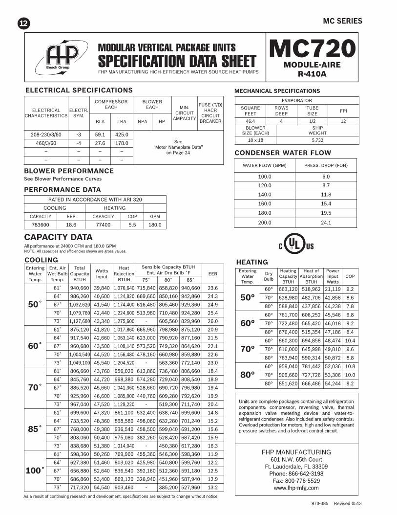
WATER FLOW (GPM) PRESS. DROP (FOH)
100.0 6.0
120.0 8.7
140.0 11.8
160.0 15.4
180.0 19.5
200.0 24.1
ELECTRICAL SPECIFICATIONS
PERFORMANCE DATA
BLOWER PERFORMANCESee Blower Performance Curves
HEATING
CONDENSER WATER FLOW
CAPACITY DATAAll performance at 24000 CFM and 180.0 GPMNOTE: All capacities and efficiencies shown are gross values.
MC720 MODULE-AIRE
R-410A
MECHANICAL SPECIFICATIONS
As a result of continuing research and development, specifications are subject to change without notice.
MODULAR VERTICAL PACKAGE UNITSSPECIFICATION DATA SHEETFHP MANUFACTURING HIGH-EFFICIENCY WATER SOURCE HEAT PUMPS
RATED IN ACCORDANCE WITH ARI 320
COOLING HEATING
CAPACITY EER CAPACITY COP GPM
783600 18.6 77400 5.5 180.0
EnteringWaterTemp.
DryBulb
HeatingCapacityBTUH
Heat ofAbsorptionBTUH
PowerInputWatts
COP
50°60° 663,120 518,962 21,119 9.2
70° 628,980 482,706 42,858 8.6
80° 588,840 437,856 44,238 7.8
60°60° 761,700 606,252 45,546 9.8
70° 722,480 565,420 46,018 9.2
80° 676,400 515,354 47,186 8.4
70°60° 860,300 694,858 48,474 10.4
70° 816,000 645,998 49,810 9.6
80° 763,940 590,314 50,872 8.8
80°60° 959,040 781,442 52,036 10.8
70° 909,660 727,726 53,306 10.0
80° 851,620 666,486 54,244 9.2
Units are complete packages containing all refrigerationcomponents: compressor, reversing valve, thermalexpansion valve metering device and water-to-refrigerant condenser. Also included are safety controls:Overload protection for motors, high and low refrigerantpressure switches and a lock-out control circuit.
FHP MANUFACTURING601 N.W. 65th Court
Ft. Lauderdale, FL 33309Phone: 866-642-3198Fax: 800-776-5529www.fhp-mfg.com
ELECTRICALCHARACTERISTICS
ELECTR. SYM.
COMPRESSOREACH
BLOWEREACH MIN.
CIRCUITAMPACITY
FUSE (T/D)HACRCIRCUITBREAKER RLA LRA NPA HP
208-230/3/60 -3 59.1 425.0See
“Motor Nameplate Data”on Page 24
460/3/60 -4 27.6 178.0
– – – –
– – – –
EVAPORATOR
SQUAREFEET
ROWSDEEP
TUBESIZE
FPI
46.4 4 1/2 12BLOWER
SIZE (EACH)SHIP
WEIGHT
18 x 18 5,732
EnteringWaterTemp.
Ent. AirWet BulbTemp.
TotalCapacityBTUH
WattsInput
HeatRejectionBTUH
Sensible Capacity BTUHEnt. Air Dry Bulb ˚F EER
75˚ 80˚ 85˚
50˚
61˚ 940,660 39,840 1,076,640 715,840 858,820 940,660 23.6
64˚ 986,260 40,600 1,124,820 669,660 850,160 942,860 24.3
67˚ 1,032,620 41,540 1,174,400 616,480 805,460 929,360 24.9
70˚ 1,079,760 42,440 1,224,600 513,980 710,480 924,280 25.4
73˚ 1,127,680 43,340 1,275,600 - 605,560 829,960 26.0
60˚
61˚ 875,120 41,820 1,017,860 665,960 798,980 875,120 20.9
64˚ 917,540 42,660 1,063,140 623,000 790,920 877,160 21.5
67˚ 960,680 43,500 1,109,140 573,520 749,320 864,620 22.1
70˚ 1,004,540 44,520 1,156,480 478,160 660,980 859,880 22.6
73˚ 1,049,100 45,540 1,204,520 - 563,360 772,140 23.0
70˚
61˚ 806,660 43,760 956,020 613,860 736,480 806,660 18.4
64˚ 845,760 44,720 998,380 574,280 729,040 808,540 18.9
67˚ 885,520 45,660 1,041,360 528,660 690,720 796,980 19.4
70˚ 925,960 46,600 1,085,000 440,760 609,280 792,620 19.9
73˚ 967,040 47,520 1,129,220 - 519,300 711,740 20.4
85˚
61˚ 699,600 47,320 861,100 532,400 638,740 699,600 14.8
64˚ 733,520 48,360 898,580 498,060 632,280 701,240 15.2
67˚ 768,000 49,380 936,540 458,500 599,040 691,200 15.6
70˚ 803,060 50,400 975,080 382,260 528,420 687,420 15.9
73˚ 838,680 51,380 1,014,040 - 450,380 617,280 16.3
100˚
61˚ 598,360 50,260 769,900 455,360 546,300 598,360 11.9
64˚ 627,380 51,460 803,020 425,980 540,800 599,760 12.2
67˚ 656,880 52,640 836,540 392,160 512,360 591,180 12.5
70˚ 686,860 53,400 869,120 326,940 451,960 587,940 12.9
73˚ 717,320 54,540 903,460 - 385,200 527,960 13.2
COOLING
MC SERIES

970-385 Revised 0513NOTE: PERFORMANCE IS AT ARI 320 RATING CONDITIONS. CAPACITY IS GROSS.
PHYSICAL DATA SPECIFICATIONSMC - SERIES MODEL
360 480 600 720
PERFORMANCE
COOLING CAPACITY - TONS 32.6 41.7 53.0 65.0EER 18.6 19.0 19.0 18.6WATER FLOW - GPM 90 120 150 180HEATING CAPACITY - MBH 387 620 730 774COP 5.5 5.4 5.4 5.5
COMPRESSORS
QUANTITY 2 4 4 4SIZE 15 HP 10 HP 12.5 HP 15 HP
EVAPORATOR COILS
FACE AREA - SQ. FT. 22.6 45.2 45.2 45.2ROWS 4 3 4 4FPI 12 12 12 12
WATERSIDE ECONOMISER COILS
FACE AREA - SQ. FT. 22.2 44.4 44.4 44.4ROWS 3 3 3 3FPI 10 10 10 10
HOT GAS REHEAT COILS
FACE AREA - SQ. FT. 22.7 44.4 44.4 44.4ROWS 1 1 1 1FPI 8 8 8 8
HOT WATER HEATING COIL
FACE AREA - SQ. FT. 22.2 22.2 22.2 22.2ROWS (OPTIONAL) 1 (2) 1 (2) 1 (2) 1 (2)FPI 10 10 10 10
EVAPORATOR FANS & MOTORS
QUANTITY 1 2 2 2SIZE - CLASS II 18 X 18 18 X 18 18 X 18 18 X 18MIN. HP EACH 7.5 7.5 7.5 7.5MAX. HP EACH 20 15 20 20NOMINAL CFM 12,200 16,000 20,000 24,000MINIMUM CFM CV 9,600 12,800 16,000 19,200MINIMUM CFM W/HOT GAS BYPASS 6,000 8,000 10,000 12,000MINIMUM CFM VAV 6,000 8,000 10,000 12,000MAXIMUM DESIGN CFM 12,400 19,200 24,000 24,800STANDARD MOTORS 15 10 15 15
FILTERS
QUANTITY 8 16 16 16NOMINAL SIZE (INCHES) 17 X 27 X 4 17 X 27 X 4 17 X 27 X 4 17 X 27 X 4
CONDENSERS
QUANTITY MANIFOLDED CIRCUITS 2 4 4 4TYPE TUBE IN TUBE COAXIALMAX. REF. WORKING PSIG 450 450 450 450MAX. H20 WORKING PSIG 400 400 400 400MIN. ENT. FLUID TEMP 45 45 45 45MAX. ENT. FLUID TEMP 110 110 110 110
MC SERIES 13

970-385 Revised 0513
14
CFM GPM
MC360 12,000
MC480 16,000
MC600 20,000
MC720 24,000
609090120120150150180
336.0378.0504.0552.0620.0660.0716.0756.0
258.0276.0364.0384.0452.0472.0536.0552.0
• Capacities at 80˚F DB, 67˚F WB entering air and 45.0˚F entering water.
AIRFLOW
To obtain economizer performance multiply the base performance by the CFM correctionfactor, entering air correction factor and entering fluid temperature factor as applicable
WATER-SIDE ECONOMIZER PERFORMANCECOOLING CAPACITY
TOTAL MBH SENSIBLE MBH
PERCENTAGE CFM
-20%
-10%
STANDARD
+10%
+20%
TOTAL COOLING CAPACITY
0.920
0.960
1.000
1.040
1.080
SENSIBLE COOLING CAPACITY
0.870
0.930
1.000
1.060
1.120
CORRECTION FACTORS
ENTERING AIR TEMPERATURE
ENTERING WB TOTAL CAPACITY˚F CORRECTION
57 0.851
61 0.910
64 0.955
67 1.000
73 1.090
78 1.164
SENSIBLE CAPACITY CORRECTION
ENTERING DB °F
ENTERING FLUID TEMPERATURE
ENTERING FLUIDTEMPERATURE ˚F
455055606570
TOTAL COOLING CAPACITY
1.0000.7900.6100.4700.3500.240
SENSIBLE COOLING CAPACITY
1.0000.8900.7800.4700.3500.240
70
0.961
0.763
0.615
75
1.030
0.881
0.733
80
1.148
1.000
.703
85
1.267
.970
.723
95
1.257
MC SERIES

970-385 Revised 0513
15
MC360
MC480
MC600
MC720
60
120
120
120
6,000
12,000
14,000
8,000
16,000
18,000
16,000
20,000
24,000
20,000
24,000
28,000
349
488
523
558
808
856
808
898
976
898
976
1046
113.4
97.3
94.3
124.0
106.3
103.6
106.3
101.2
97.3
101.2
97.3
94.3
168.4
163.7
162.6
170.7
166.5
165.7
166.5
165.0
163.7
165.0
163.7
162.6
MODEL WATERGPM
AIRFLOW CFM
CAPACITYMBH
LEAVING AIR˚F
LEAVING WATER˚F
Coil performance is based on entering air temperature of 60˚F and 180˚F entering water.Please contact your FHP representative for performance at other conditions and two row coil performance data.
ONE ROW HOT WATER COIL CAPACITY
MC SERIES

970-385 Revised 0513
16
WATER-SIDE COMPONENT PRESSURE DROPS - (Ft. of H20)
NOTE: ECONOMISER PRESSURE DROP INCLUDES MOTORIZED BALL VALVE AND ALL ASSOCIATED PIPING.HOT WATER COIL IS 1 ROW
NOTE: 1) Cooling coil and economiser coil shown with wet surface.2) Reheat coil and hot water coil shown dry.3) Filters shown clean.4) Two-row hot water coil shown.
GPM
60
70
80
90
90
100
110
120
120
130
140
150
150
160
170
180
CONDENSERS
8.7
11.8
15.4
19.5
8.4
10.3
12.6
15.0
8.7
10.1
11.7
13.5
13.5
15.4
17.4
19.5
ECONOMISER
13.1
17.9
23.5
29.8
7.3
9.1
11.0
13.1
13.1
15.4
17.9
20.6
20.6
23.5
26.5
29.8
HOT WATER COIL
4.2
5.7
7.5
9.5
2.6
2.9
3.5
4.2
4.2
4.9
5.7
6.6
6.6
7.5
8.5
9.5
MODEL
MC360
MC480
MC600
MC720
AIR-SIDE PRESSURE DROPS - (INCHES OF H2O)
MODEL CFMCOILS FILTERS
FACEVELOCITYCOOLING ECONOMISER REHEAT
HOTWATER
4" - 30% 4" - 65%
MC360
8,000 0.35 0.25 0.06 0.12 0.07 0.24 345
10,000 0.53 0.32 0.07 0.17 0.12 0.30 431
12,000 0.77 0.47 0.12 0.25 0.19 0.43 517
13,000 0.90 0.56 0.15 0.29 0.22 0.51 560
MC480
12,000 0.26 0.15 0.02 0.06 0.05 0.10 259
14,000 0.36 0.20 0.04 0.09 0.06 0.14 302
16,000 0.47 0.26 0.05 0.11 0.09 0.19 345
18,000 0.59 0.33 0.06 0.15 0.11 0.24 388
MC600
16,000 0.35 0.25 0.06 0.12 0.07 0.24 345
18,000 0.43 0.28 0.07 0.16 0.10 0.26 388
20,000 0.53 0.32 0.07 0.17 0.12 0.30 431
22,000 0.64 0.40 0.12 0.24 0.15 0.40 474
MC720
20,000 0.53 0.32 0.07 0.17 0.12 0.30 431
22,000 0.64 0.40 0.12 0.24 0.15 0.40 474
24,000 0.77 0.47 0.12 0.25 0.19 0.43 517
25,000 0.84 0.52 0.14 0.26 0.20 0.47 539
MC SERIES

970-385 Revised 0513
17
BLOWER PERFORMANCE
MC360
MC480 - 720
1000 CFM
MC SERIES

970-385 Revised 0513
18
NOTE: 1) For the specific application CFM and TSP select the part number and motor HP.2) MB480, 600 and 720 require a quantity of 2 drive packages.
DRIVE SELECTION TABLE
CFM
TOTAL STATIC PRESSURE - INS WATER
2.0 2.5 3.0 3.5 4.0 4.5
DrivePart # HP Drive
Part # HP DrivePart # HP Drive
Part # HP DrivePart # HP Drive
Part # HP
041 041 041 041 041 041
MC360
9,500 -002 7.5 -006 15 -011 10 -018 15 -024 15 -030 15
10,000 -002 7.5 -008 10 -011 10 -017 15 -024 15 -030 15
10,500 -040 10 -008 10 -014 15 -018 15 -024 15 -030 15
11,000 -040 10 -008 10 -014 15 -017 15 -024 15 -030 15
11,500 -006 15 -009 15 -014 15 -018 15 -024 15 -031 20
12,000 -006 15 -012 15 -014 15 -021 15 -025 20 -030 20
12,500 -006 15 -012 15 -018 15 -022 20 -025 20 -031 20
13,500 -009 15 -015 20 -019 20 -022 20 -027 20 - -
MC480 - REQUIRES TWO MOTORS
13,000 000 7.5 -007 7.5 -013 7.5 -023 7.5 -041 10 -036 10
14,000 000 7.5 -005 7.5 -013 7.5 -020 10 -029 10 -036 10
15,000 000 7.5 -005 7.5 -013 7.5 -020 10 -029 10 -037 15
16,000 000 7.5 -005 7.5 -013 7.5 -017 10 -026 10 -037 15
17,000 000 7.5 -005 7.5 -013 7.5 -017 10 -024 15 -042 15
18,000 -002 7.5 -005 7.5 -011 10 -017 10 -024 15 -030 15
19,000 -002 7.5 -006 15 -011 10 -018 15 -024 15 -030 15
MC600 - REQUIRES TWO MOTORS
16,000 000 7.5 -005 7.5 -013 7.5 -017 10 -026 10 -037 15
17,000 000 7.5 -005 7.5 -013 7.5 -017 10 -024 15 -042 15
18,000 -002 7.5 -005 7.5 -011 10 -017 10 -024 15 -030 15
19,000 -002 7.5 -006 15 -011 10 -018 15 -024 15 -030 15
20,000 -002 7.5 -008 10 -011 10 -017 15 -024 15 -030 15
21,000 -040 10 -008 10 -014 15 -018 15 -024 15 -030 15
22,000 -040 10 -008 10 -014 15 -017 15 -024 15 -030 15
23,000 -006 15 -009 15 -014 15 -018 15 -024 15 -031 20
24,000 -006 15 -012 15 -014 15 -021 15 -025 20 -030 20
MC720 - REQUIRES TWO MOTORS
19,000 -002 7.5 -006 15 -011 10 -018 15 -024 15 -030 15
20,000 -002 7.5 -008 10 -011 10 -017 15 -024 15 -030 15
21,000 -040 10 -008 10 -014 15 -018 15 -024 15 -030 15
22,000 -040 10 -008 10 -014 15 -017 15 -024 15 -030 15
23,000 -006 15 -009 15 -014 15 -018 15 -024 15 -031 20
24,000 -006 15 -012 15 -014 15 -021 15 -025 20 -030 20
25,000 -006 15 -012 15 -018 15 -022 20 -025 20 -031 20
MC SERIES

970-385 Revised 0513
19
NET WEIGHT IN LBS.
MC SERIES SHIPPING WEIGHTS (LBS)
MODEL MC360 MC480 MC600 MC720 MC360 MC480 MC600 MC720
VH CONFIGURATION VL CONFIGURATION
MAIN AIR CONDITIONING SECTION (EACH)
NUMBER OF SECTIONS 1 2 2 2 1 2 2 2
MAIN SECTION EACH 1,450 1,175 1,550 1,575 2,100 1,825 2,200 2,225
REHEAT COIL OPTION EACH 40 40 40 40 40 40 40 40
FILTER/ECONOMISER SECTIONS (EACH)
NUMBER OF SECTIONS 1 2 2 2 1 2 2 2
FILTER SECTION 310 310 310 310 310 310 310 310
ECONOMISER OPTION 200 200 200 200 200 200 200 200
BLOWER SECTION (EACH)
NUMBER OF SECTIONS 1 2 2 2
INCLUDED IN MAIN AC SECTIONFAN SECTION (MAX MOTOR
SIZE) 650 650 650 650
TOTAL UNIT
NUMBER OF SECTIONS 3 6 6 6 2 4 4 4
TOTAL UNIT WITH OPTIONS 2,650 4,750 5,500 5,550 2,650 4750 5500 5550
MC SERIES

970-385 Revised 0513
20 MC SERIES

970-385 Revised 0513
21MC SERIES

970-385 Revised 0513
22 MC SERIES

970-385 Revised 0513
23MC SERIES

970-385 Revised 0513
24
UNIT ELECTRICAL SPECIFICATIONS
GeneralWiring must comply with applicable codes.A single power block is provided for power cables to the unit.Each individual module has it’s own terminal block and wiring between sections follows the concept of single pointpower supply.
Unit DisconnectUnit disconnects are required under Article 440 of the National Electric Code. The disconnect switch should belocated in accordance with NEC guidelines. Unit disconnects are not factory installed.
NOTES:1. Model MC 360 uses one motor/blower assembly2. Models MC 480,600 and 720 use 2 motor/blower assemblies3. All motors are high efficiency open drip proof and meet all EPACT efficiency requirements.4. Service factor is 1.15 on all motors.
NOTE: All units are three phase power supply. Check compressor and blower rotations at start-up. See unitnameplate for allowable voltage tolerances.
Power lead wire sizing.Minimum circuit ampacity: (largest load x 1.25) + all other loadsMax fuse size: (largest load x 2.25) + all other loads - use next smaller fuse size.All wiring to be in accordance with N.E.C. table 310-16 or 310-19
MOTOR NAMEPLATE DATA
HORSEPOWER230-3-60 460-3-60 575-3-60
FLA FLA FLA
7.5 19.4 9.7 7.8
10.0 25.2 12.6 10.3
15.0 38.6 19.3 15.4
20.0 49.6 24.8 19.8
COMPRESSOR NAMEPLATE DATA
MODEL QTY.230-3-60 460-3-60
RLA (EA.) LRA (EA.) RLA (EA.) LRA (EA.)
MC360 2 59.1 425 27.6 178
MC480 4 37.0 239 20.0 125
MC600 4 53.6 245 20.7 125
MC720 4 59.1 425 27.6 178
MC SERIES

970-385 Revised 0513
25MCS CONTROLLE
R
TYPICAL W
IRING DIAGRAM
MC SERIES

970-385 Revised 0513
26 MC SERIES

970-385 Revised 0513
27MC SERIES

970-385 Revised 0513
28
GENERAL
Furnish and install where shown on plans, FHPManufacturing MC Series self-contained packaged airconditioning unit. Capacities, models and unitarrangement shall be as shown on the unit schedule andthe contract drawings. Units shall be listed for UL andCUL. Units shall conform to ANSI/UL standard 1995. Unitshall be accepted for use in the City of New York by theDepartment of Buildings (MEA). Each unit shall becompletely factory assembled, piped, wired and tested.Units shall be leak tested and charged with a fulloperating charge of Refrigerant 410A. Units shall then bedisassembled into their individual modules for shippingand assembly on site. Installation and maintenancemanuals and wiring diagrams shall be supplied with eachunit. Factory test shall include, but not be limited to:complete run check of all electrical components andsafeties, including proper control sequencing; pressuretest of refrigerant coils and condensers; leak check ofcompleted refrigerant circuits; leak check of completedwater circuit; compressor run check.
CABINET
VH CONFIGURATION:The unit shall be comprised of three distinct modules: 1)Main cooling/heating, 2) Filter/waterside economizer, and3) Fan section. The unit shall be designed for easyassembly. The refrigeration circuit shall remain intactduring disassembly/assembly. All modules shall be able topass through a 36" steel framed door. The frame shall befabricated of an angle iron framework. Unit exterior panelsshall be 18 gauge G90 galvanized steel for corrosionprotection. Each section shall incorporate removableaccess panels. The complete cabinet frame and accesspanels shall be insulated with 1/2 inch, dual densityNeoprene backed fiberglass fiber insulation. The maincooling/heating section and the filter/waterside economizersection shall contain a galvanized steel drain pan coatedwith archem type paint for corrosion resistance.
VL CONSTRUCTION:The unit shall be comprised of two distinct modules: 1)Main cooling/heating section with blower(s) and motor(s) 2)Filter/waterside economizer section. The unit shall bedesigned for easy assembly. The refrigeration circuit shallremain intact during disassembly/assembly. The frameshall be fabricated of an angle iron framework. Unit exterior
panels shall be 18 gauge G90 galvanized steel forcorrosion protection. Each section shall incorporateremovable access panels. The complete cabinet frame andaccess panels shall be insulated with 1/2 inch, dual densityNeoprene backed fiberglass fiber insulation. The maincooling/heating section and the filter/waterside economizersection shall contain a galvanized steel drain pan coatedwith archem type paint for corrosion resistance.
EVAPORATORThe direct expansion coil shall be a minimum of 3 rows andfabricated from 3/8" or 1/2" O.D. seamless copper tubingmechanically bonded to rippled and corrugated aluminumfins. Each individual evaporator coil shall be removable forreplacement without disturbing the remaining refrigerantcircuits. Each evaporator coil circuit shall be fed by anadjustable thermostatic expansion valve, with externalequalizer, sized to provide efficient operation at full and atpart load operating points in the cooling and heating modes.
SUPPLY FANSupply fans shall be double width, double inlet forwardcurved type of Class II construction. All fans shall bestatically and dynamically balanced. Fan shafts shall bemounted in heavy duty 150,000 hour greaseable pillowblock bearings. The fan motor shall be open drip proofthree phase, NEMA T frame E high efficiency EPACTrated, 1800 rpm, with grease lubricated ball bearings.The drive shall include fixed pitch sheaves with multipleV belts sized for 115% of the fan brake horsepower.
REVERSE CYCLE OPERATIONUnits shall be equipped with reversing valves to allowoperation in the reverse cycle heating mode. Electricheaters shall not be allowed as a substitute.
VARIABLE AIR VOLUME, (OPTIONAL)
Airflow modulation shall be achieved by the use of afactory controlled variable frequency drive. The unitshall be able to operate at 100% of rated airflow in theevent of a failure of the VFD. Static pressure shall becontrolled by the unit mounted MCS controller. Staticpressure to be sensed by field installed duct sensors.The installer to provide and install wiring from thesensor to the unit mounted controller. The staticpressure setpoint shall be keypad adjustable throughthe MCS controller.
GUIDESPECIFICATIONS
MC SERIESVERTICAL PACKAGE UNITSFHP MANUFACTURING
ENERGY WISE HVAC EQUIPMENT
MC SERIES

970-385 Revised 0513
29
REFRIGERATION CIRCUIT
Each unit shall contain multiple independent refrigerationcircuits. Each circuit shall include a high efficiencyheavy-duty scroll compressors. Each circuit shall havehigh and low pressure cutouts. Each circuit shall bedehydrated and factory charged with Refrigerant 410A.Suction and discharge schrader valves shall be provided formanifold gauge connections to facilitate servicing. Optionalhot gas bypass shall be provided to allow unit operationunder extended operating conditions avoiding coil freeze up.
COMPRESSORS
Each unit shall have multiple high efficiency scrollcompressors with internal or external motor protection anda time delay to prevent short cycling and simultaneousstarting of compressors following a power failure. Eachcompressor shall be on an independent refrigerant circuit.The compressors shall be mounted on rubber isolators.
CONDENSERS
All condensers shall be coaxial tube-in-tube formaximum heat transfer efficiency and performance.Inner water tubes shall be either copper or optionalcupro-nickel with large internal diameters for reducedwaterside pressure drops. Outer tubes shall be steel,painted for corrosion protection. All condensers shall berated at 450 PSIG operating refrigerant pressures and400 PSIG waterside pressures. Units shall be rateddown to 45°F without the use of water regulating valves.
WATERSIDE ECONOMIZER, (OPTIONAL)
A complete waterside economizer package shall be provided,including coil, control valves and factory piping. The completeeconomizer package shall be rated for 400 psig watersideworking pressure. Economizer operation shall be controlledto maximize free cooling operation. Economizer shall beenabled by the optional MCS controller whenever theentering water temperature is less than an adjustable setpoint. Water flow shall pass through the economizer coil andcondenser in series while in the economizer operating modeand shall bypass the economizer coil while not calling foreconomizer operation. Mechanical cooling or heating shall beenabled during economizer operation.
HOT WATER PREHEAT, (OPTIONAL)
Hot water coils shall be 1 or 2 rows, fabricated from1/2"O.D. seamless copper tubing mechanically bondedto rippled and corrugated aluminum fins. Coil shall befield mounted.
HOT GAS REHEAT, (OPTIONAL)
Provide a one row hot gas reheat coil to allow the unitto operate in the dehumidification mode. Control of thehot gas reheat shall be provided by the unit controller.
FILTER SECTION
The unit shall be supplied with 4" deep pleated, 30%high efficiency filters. The filters shall have side accesscapability through an access panel.
ELECTRICAL
Each unit shall be wired and tested at the factory prior toshipment. Wiring shall comply with NEC requirementsand shall conform with all applicable UL standards. Theunits shall have a single point power connection. Thecontrol power shall be supplied through a factoryinstalled, low voltage control circuit transformer with anintegral resettable circuit breaker. The fan motor startershall have a magnetic three line, ambient compensatedoverload protector with a manual reset. A terminal blockshall be provided for the main power connection.
Each unit shall be provided with a Unit ProtectionModule (UPM) that controls compressor operation andmonitors the safety controls that protect the unit.
Safety controls include the following:
• High pressure switches located in the refrigerantdischarge lines. One per refrigeration unit.
• Low pressure switches for loss of charge protectionlocated in the unit refrigerant suction lines. One perrefrigeration unit.
• Optional freeze protection sensor located on theleaving side of the water coil prevents unitoperation below 35ºF. Freeze terminals must bejumped together if the freeze sensor is not installed.
• Condensate overflow protection sensor located inthe drain pan(s) of the unit and wired to the UPMboard.
The UPM includes the following features:
• ANTI-SHORT CYCLE TIMER – 5 minute delay onbreak timer to prevent compressor short cycling.
• RANDOM START – Each controller has a uniquerandom start delay ranging from 270 to 300 seconds.
• LOW PRESSURE BYPASS TIMER – The lowpressure switch will be bypassed for 120 seconds aftercompressor start-up to prevent nuisance low pressurelockouts during cold start-up in the heating mode.
• BROWNOUT/SURGE/POWER INTERRUPTIONPROTECTION – a 20 millisecond window is to bemonitored for the above condition. Should any of theseconditions be detected, the 5-minute delay on breaktimer and the random start timer delay are initiated.
• MALFUNCTION OUTPUT – The controller shallhave a set of wet contacts for remote faultindication.
• TEST SERVICE PIN – A jumper pin is to be providedto reduce all time delay settings to 5 seconds duringtroubleshooting or verification of unit operation.
• L.E.D. FAULT INDICATION – Two L.E.D. indicators areprovided as follows:
• GREEN: Power L.E.D. indicates 18 – 30 VAC presentat the board.
• RED: Fault indicator with blink codes as follows:
MC SERIES

970-385 Revised 0513
30
• ONE BLINK 1st Stage high pressure lockout
• TWO BLINKS 1st Stage low pressure lockout
• THREE BLINKS 2nd Stage high pressure lockout
• FOUR BLINKS 2nd Stage low pressure lockout
• FIVE BLINKS Freeze protection lockout
• SIX BLINKS Condensate overflow lockout
• SEVEN BLINKS Brown Out
• INTELLIGENT RESET - If a fault condition is initiatedthe 5 minute delay on break time period and therandom start timer are initiated and the unit will restartafter these delays expire. If the fault condition stillexists or reoccurs within one hour, the unit will go intoa hard lockout and requires a manual lockout reset.
• LOCKOUT RESET - A hard lockout can be reset byturning the unit thermostat off and then back on or byshutting off unit power at the circuit breaker.
NOTE: The blower motor will remain active duringa lockout condition.
(OPTIONAL)AUXILIARY CONTROL OPTIONSA pressure differential type water flow switch shall beprovided, factory installed, to verify water flow status atthe unit. Compressor operation shall be disabled andan alarm signal provided if condenser water flow is lost.Unit operation will be restored when water flow hasbeen reestablished.
MC SERIES

31
NOTES
MC SERIES

970-385 Revised 0513
LARGEVERTICALMODELS6-60 TONS
SMALLVERTICALMODELS
1/2 - 5 TONS
SMALLHORIZONTALMODELS
1/2 - 5 TONSCONSOLEMODELS
3/4 - 11/2 TONS
PRODUCT OFFERING• Vertical Units ..............................................................................................................................1/2 - 60 Tons• Horizontal Units .........................................................................................................................1/2 - 20 Tons• Console Units ...........................................................................................................................3/4 - 11/2 Tons• Rooftop Units ..............................................................................................................................4 - 35 Tons• Water to Water Chillers / Boilers .................................................................................................3 - 35 Tons• Split Systems .............................................................................................................................1/2 - 25 Tons• Variable Air Volume ....................................................................................................................6 - 60 Tons
FACTORY INSTALLED OPTIONS• Hot Gas Reheat ( Dehumidification ) • 100% Outside / Make up Air Units• Water-side Economizer • Cupronickel Water Coil• Heat Recovery ( Desuperheater ) • Custom Options Available Upon Request
SOFTWAREOur Engineering Application Data Software ( EAD ) is customized for the professional HVAC designer.Professional HVAC designers will find this software to be a valuable tool for equipment selection. EADSoftware is available for HVAC designers through our network of representatives. To locate the FHPrepresentative nearest you please refer to our web site at www.fhp-mfg.com.
ROOFTOP MODELS4 - 35 TONS
LARGEHORIZONTALMODELS
6 - 20 TONS
Available with
ALTERNATIVE
REFRIGERANT
R-410A
970-385
COMMERCIAL WATER SOURCE & GEOTHERMAL PRODUCTS
FHP MANUFACTURING601 N.W. 65th CourtFort Lauderdale, FL 33309866-642-3198800-776-5529 Faxwww.fhp-mfg.com


