indracompany.com
ATM
CONTROL AND
COORDINATION
SYSTEM
World leader with more than 1.000 installations in 75 countries
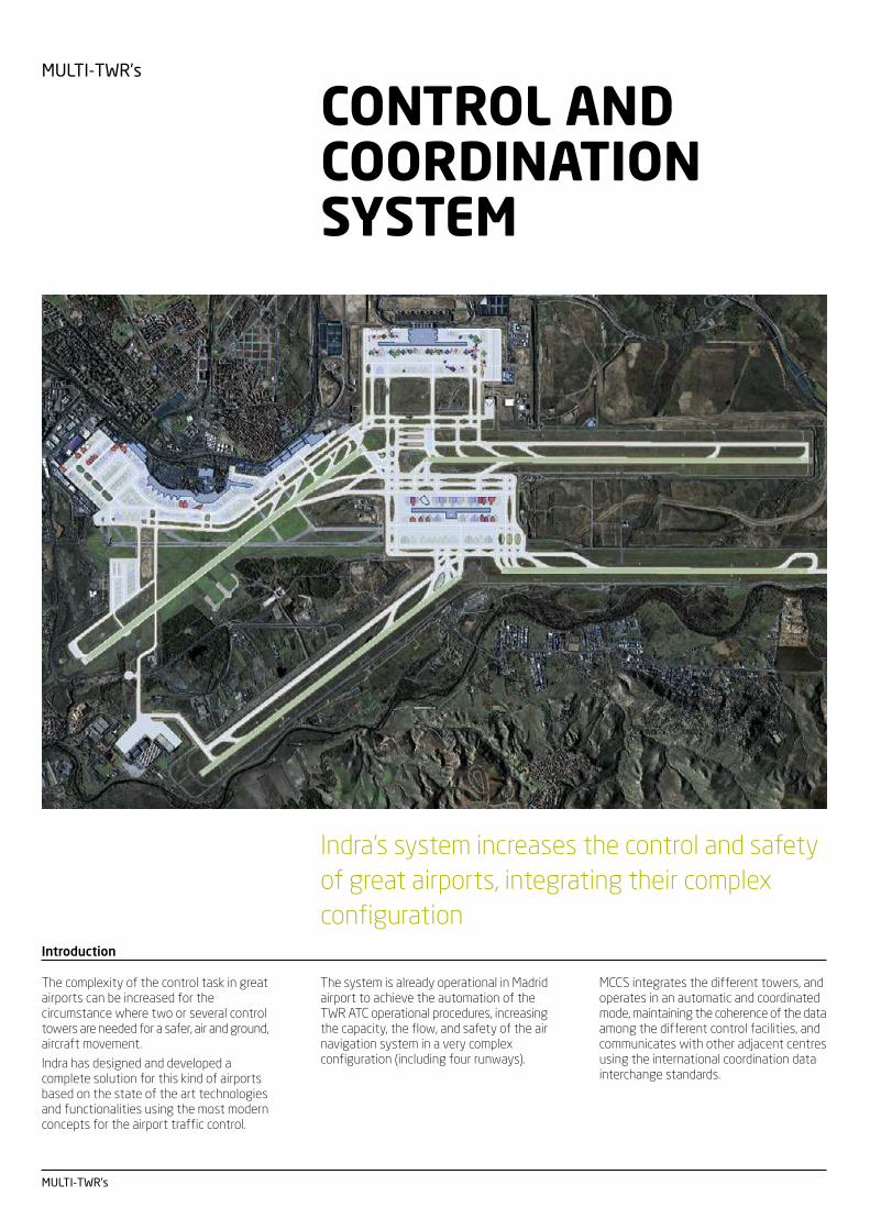
MULTI-TWR’s
MULTI-TWR’s
Indra’s system increases the control and safety
of great airports, integrating their complex
configuration
CONTROL AND
COORDINATION
SYSTEM
Introduction
The complexity of the control task in greatairports can be increased for thecircumstance where two or several controltowers are needed for a safer, air and ground,aircraft movement.
Indra has designed and developed acomplete solution for this kind of airportsbased on the state of the art technologiesand functionalities using the most modernconcepts for the airport traffic control.
MCCS integrates the different towers, andoperates in an automatic and coordinatedmode, maintaining the coherence of the dataamong the different control facilities, andcommunicates with other adjacent centresusing the international coordination datainterchange standards.
The system is already operational in Madridairport to achieve the automation of theTWR ATC operational procedures, increasingthe capacity, the flow, and safety of the airnavigation system in a very complexconfiguration (including four runways).
ATM
Surveillance data processingsubsystem (SUR)
The surveillance subsystem is in charge ofdetecting aircrafts inside the controlled area,identifying them, tracking their evolutionand providing surveillance information fortheir visualization in Control WorkingPositions (CWPs) according to A-SMGCSconcept. The subsystem performs thesefunctions in two different environmentscharacterized by the radar andmultilateration data acquisition, both air andsurface.
It processes data sent by radars and sensorsconnected to the system, using for it aprecise description of their characteristicsand the controlled area. In the same way, itaccesses to information about flight plansand aircraft tale number readers to identifythe detected aircrafts. It also provides theflight plan–radar track linkage service as wellas the alert service to the controller workingposition.
System incorporates alert detectionfunctionality for:
• Runway incursion
• Landing on wrong runway
• Distance conflict
• Not allowed movement
The following functions are supportedby this subsystem:
• Surveillance data acquisition function (airand surface)
• Air tracking function
• Data fusion and distribution function
• FP-track association function
• Safety nets function
• Meteorological data processing function
Flight Data Processing Subsystem(FDPS)
The Flight Plan Subsystem (FPS) is in chargeof the management of flight planinformation specific for tower controlsystems.
The main functions performed are thefollowing:
• Reception of flight plans coming from themain external system (ACC or TMA FPDS)
• Reception of flight plans from the AFTNline in case of unavailability of the mainsystem (ACC or TMA FPDS)
• Management of abbreviated flight plancreated by the controller
• Attention to the tower controller actions,and particularly, the management of thedifferent clearances
• Flight plans supply to FP-TRACKassociation functionality on thesurveillance subsystem (SUR)
• Support for the CWP degraded mode
The following functions are supportedwith the available FPs information:
• FP data distribution to the correspondingcontroller workstations
• Electronic flight strip facility (EFS)
• FP state control, taking into account thecontroller commands and the automaticevents
• Support for the handover between towercontrollers and between the differenttowers
• Interface with the Radar SurveillanceSystem
• Interface with the Airport Operational DataBase (AODB)
Electronic Flight Strip (EFS) facility
The CWP system displays two main windowscorresponding to departure FPs strips andto arrival FPs strips.
Each window displays the EFSscorresponding to the flights affecting suchCWP, depending on the role assigned to it(clearance, ground or local).
The windows can be configured in differentareas for flights in specific conditions, forexample, the assumed flights separated fromthose already transferred, or the flightswhich have already a specific clearanceseparated from those which have not it yet.
There also exist windows where the FPs inde-ice or ground-hold status are displayed.
Fields composing the different strips aredefined by adaptation, with an optional fieldspecific for notes and another for free text.
The EFSs dragging allows the controller tomanually sort the EFS’s, inside a specificarea or even between different areas.Interaction with EFS’s also allows thecontroller to modify the FP or enter theclearances.
Changes to FP data, for which there exist astrip on a window, are displayed in the stripwith the modified field in highlighted state.
ATM
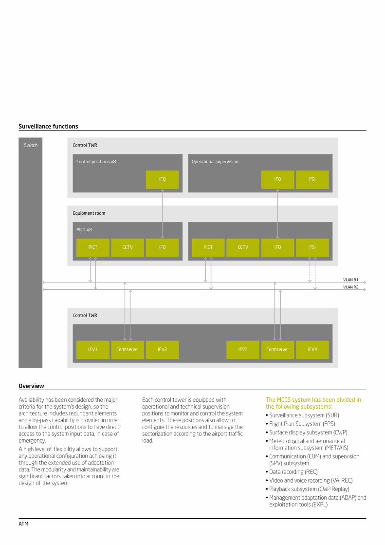
Overview
Availability has been considered the majorcriteria for the system’s design, so thearchitecture includes redundant elementsand a by-pass capability is provided in orderto allow the control positions to have directaccess to the system input data, in case ofemergency.
A high level of flexibility allows to supportany operational configuration achieving itthrough the extended use of adaptationdata. The modularity and maintainability aresignificant factors taken into account in thedesign of the system.
Each control tower is equipped withoperational and technical supervisionpositions to monitor and control the systemelements. These positions also allow toconfigure the resources and to manage thesectorization according to the airport trafficload.
The MCCS system has been divided inthe following subsystems:
• Surveillance subsystem (SUR)
• Flight Plan Subsystem (FPS)
• Surface display subsystem (CWP)
• Meteorological and aeronauticalinformation subsystem (MET/AIS)
• Communication (COM) and supervision(SPV) subsystem
• Data recording (REC)
• Video and voice recording (VA-REC)
• Playback subsystem (CWP Replay)
• Management adaptation data (ADAP) andexploitation tools (EXPL)
Surveillance functions
Control TWR
IFO
Control positions x8
IFO
Operational supervision
PSI
Switch
Equipment room
IFO
PICT x8
IFO PSICCTV CCTVPICTPICT
VLAN R1
VLAN R2
Control TWR
TermserverIFV1 IFV2 IFV3 IFV4Termserver
ATM
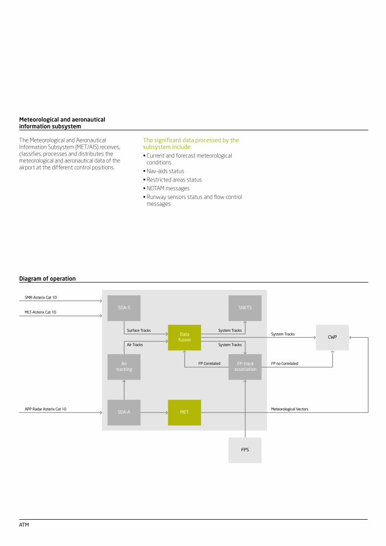
Diagram of operation
Surface Tracks
Air Tracks
SMR-Asterix Cat 10
MLT-Asterix Cat 10
APP Radar Asterix Cat 10
System Tracks
FP Correlated
System TracksSystem Tracks
Meteorological Vectors
FP no Correlated
Data
fusionCWP
SDA-A MET
FPS
Air
tracking
FP-track
association
SDA-S SNETS
Meteorological and aeronauticalinformation subsystem
The significant data processed by thesubsystem include:
• Current and forecast meteorologicalconditions
• Nav-aids status
• Restricted areas status
• NOTAM messages
• Runway sensors status and flow controlmessages
The Meteorological and AeronauticalInformation Subsystem (MET/AIS) receives,classifies, processes and distributes themeteorological and aeronautical data of theairport at the different control positions.
ATM
Voice communication subsystem
The voice communication subsystem allowsto perform all the voice communicationrequired by the air traffic controllersbetween them and aircrafts and betweenthe control positions in different towers.
The system uses the IP technology (Voiceover Internet Protocol) achieving the highestlevels of safety, quality and flexibility. Systemprovides access to the radio channels,including retransmission functions, shiftedfrequencies, multiple sites and remoteequipment supervision and to the telephonesubsystem including access to hot lines,direct access lines and indirect access linesand all kind of facilities.
The subsystem is connected to externalnetworks using, CCITT5, ISDN, ATS-R2 andATS-Q-SIG standards and provides aninterface to the automation system forautomatic reconfiguration purposes. It alsoprovides an interface with the supervisionsubsystem to maintain coherent status data,synchronization and sectorization.
The HMI interface is implemented via TFTmonitors with touch input devices.
Supervision subsystem
The supervision subsystem processessystem overall status information and makesit available to the operational and technicalsupervisors.
Each control tower is equipped withoperational and technical supervisionpositions to monitor and control the systemelements. These positions also allow toconfigure the resources and to manage thesectorization according to the airport trafficload.
The subsystem also performs automatic (incase of failure) reconfiguration of the systemresources and establishes the sectorizationof the control positions and allows theautomatic recovery of non configuredelements.
It also provides system data recordingfacilities for further exploitation off lineand/or legal recording analysis.
Dynamic simulation and supportsubsystems
The dynamic simulation subsystem providesthe capability of training to the controllersin an environment replicated from theoperational system. To achieve this goal thesimulation subsystem includes differentcontroller positions, pilot and supervisorpositions as well as a set of tools for thecreation and evaluation of the trainingexercises.
The support subsystem provides theresources required to perform the followingactivities associated to the tower ATCmanagement:
• Geographic and air space map generation
• Adaptation data base generation
• Repetitive FP generation
• Incident analysis
• Flight plan statistics
• Radar data and FP historic information
• Air traffic billing...
ATM
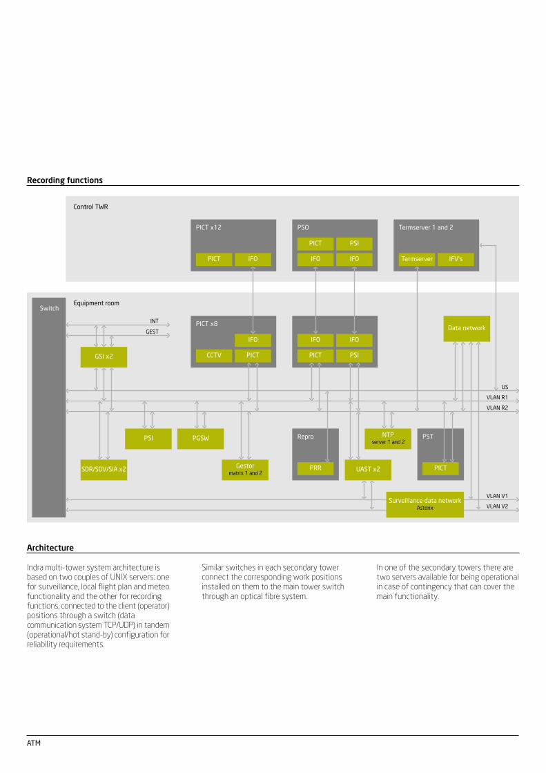
Architecture
Indra multi-tower system architecture isbased on two couples of UNIX servers: onefor surveillance, local flight plan and meteofunctionality and the other for recordingfunctions, connected to the client (operator)positions through a switch (datacommunication system TCP/UDP) in tandem(operational/hot stand-by) configuration forreliability requirements.
In one of the secondary towers there aretwo servers available for being operationalin case of contingency that can cover themain functionality.
Similar switches in each secondary towerconnect the corresponding work positionsinstalled on them to the main tower switchthrough an optical fibre system.
Recording functions
Equipment room
IFO
PSIPICT
IFOIFO
PICT x8
PICTCCTV
Control TWR
Switch
VLAN R1
VLAN R2
US
VLAN V1
VLAN V2
NTPserver 1 and 2
UAST x2Gestor
matrix 1 and 2
PGSWPSI
SDR/SDV/SIA x2
Surveillance data networkAsterix
Data network
GSI x2
PSI
IFOIFO
PICT
PSO Termserver 1 and 2
IFV’sTermserver
PICT
PST
PRR
Repro
INT
GEST
PICT
PICT x12
IFO

Ctra de Loeches, 928850 Torrejón de ArdozMadrid (Spain)T + 34 91 627 11 47F + 34 91 627 10 05indracompany.com
Indra reserves the rightto modify thesespecifications withoutprior notice.


![Atm 1204-Chapter 2[Aerodrome Control]](https://cdn.vdocument.in/doc/165x107/577cd3bd1a28ab9e78976ff4/atm-1204-chapter-2aerodrome-control.jpg)

