ATM Frame
Last Update 2011.06.01
1.0.0
Copyright 2011 Kenneth M. Chipps Ph.D. www.chipps.com
1
Objectives of This Section
• Learn– What an ATM frame looks like
Copyright 2011 Kenneth M. Chipps Ph.D. www.chipps.com 2
Channelized ATM Configuration
• When used as a way to replace a large number of T1 circuits coming into a site a service provider’s SONET/ATM MAN can be extended to a customer’s location as Channelized ATM
• For example here is a site that once had 200 T1 lines connecting to it as part of a hub and spoke network
• Here is the original setupCopyright 2011 Kenneth M. Chipps Ph.D. www.chipps.com 3
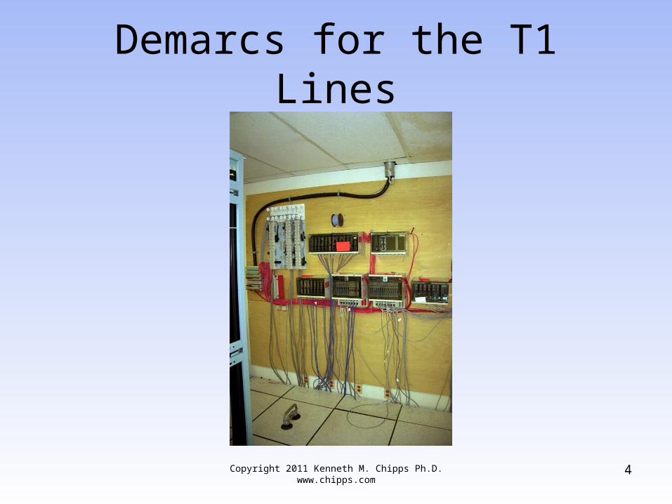
Demarcs for the T1 Lines
Copyright 2011 Kenneth M. Chipps Ph.D. www.chipps.com 4
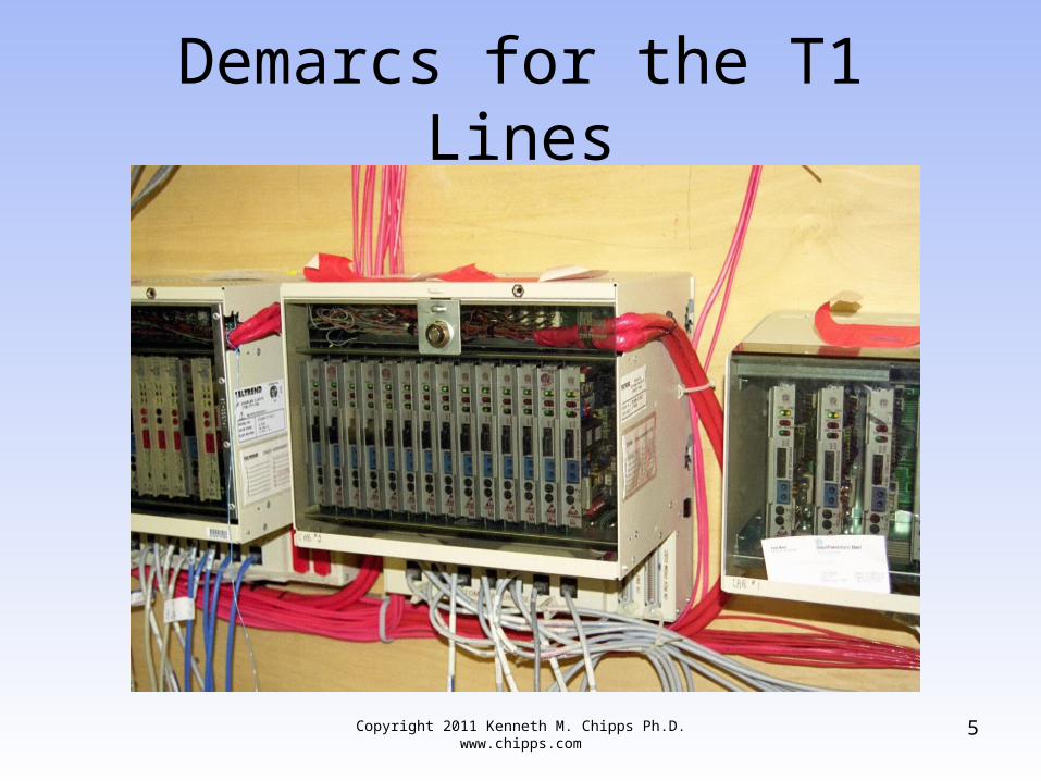
Demarcs for the T1 Lines
Copyright 2011 Kenneth M. Chipps Ph.D. www.chipps.com 5
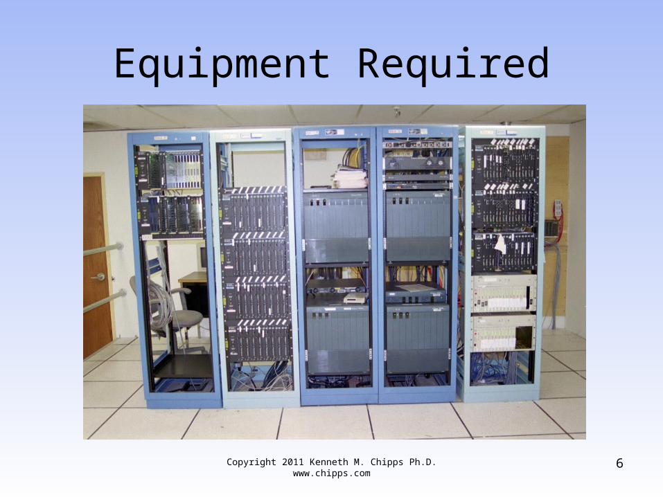
Equipment Required
Copyright 2011 Kenneth M. Chipps Ph.D. www.chipps.com 6
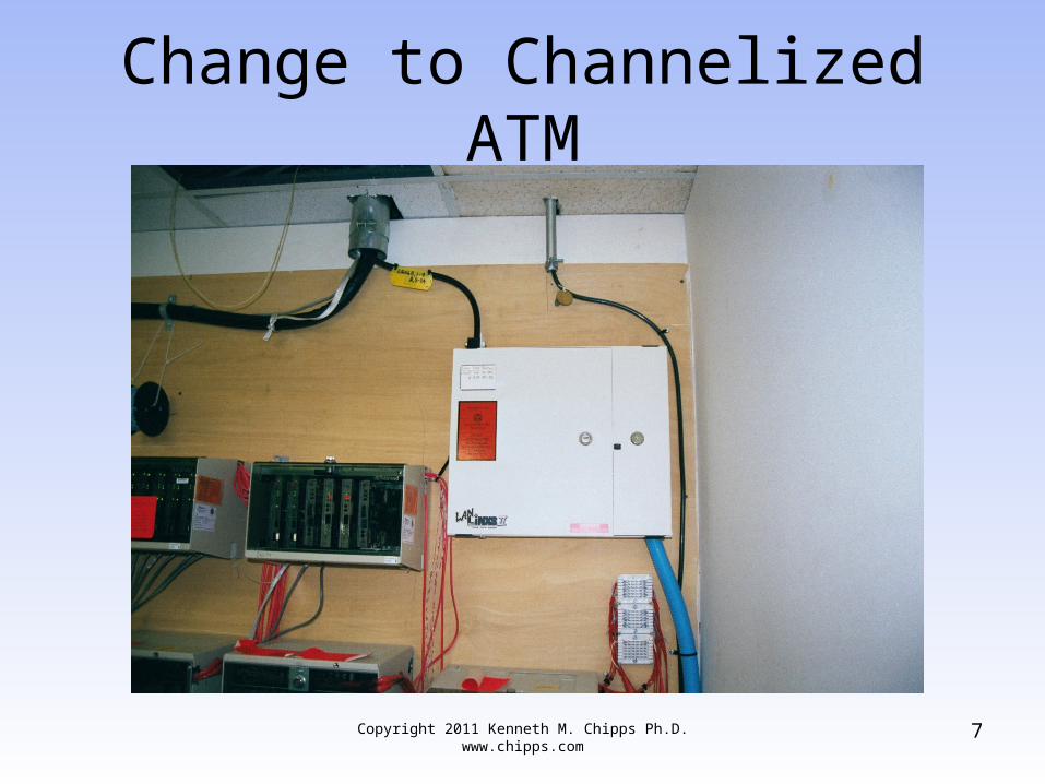
Change to Channelized ATM
Copyright 2011 Kenneth M. Chipps Ph.D. www.chipps.com 7
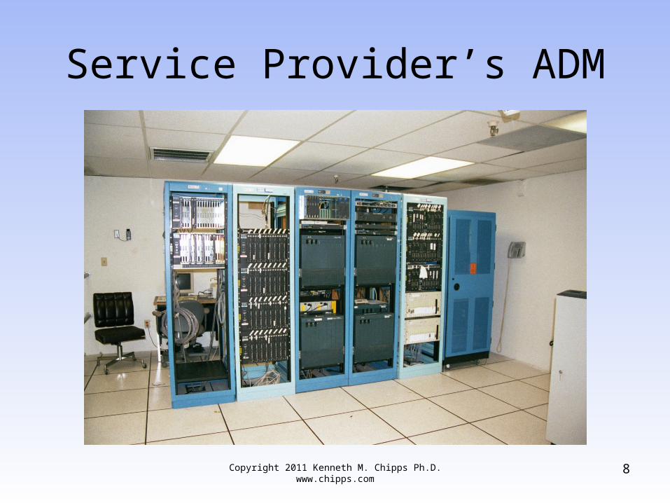
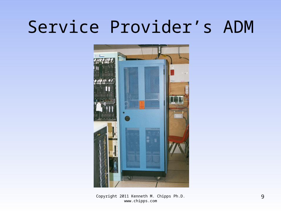
Service Provider’s ADM
Copyright 2011 Kenneth M. Chipps Ph.D. www.chipps.com 8
Service Provider’s ADM
Copyright 2011 Kenneth M. Chipps Ph.D. www.chipps.com 9
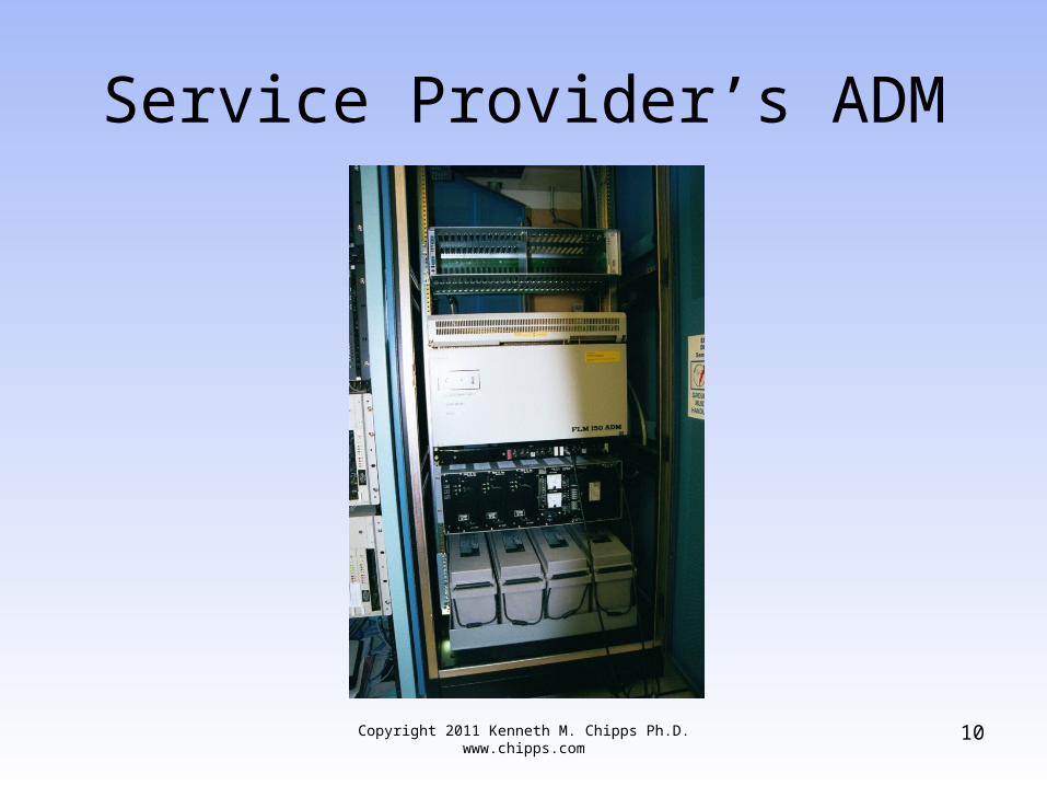
Service Provider’s ADM
Copyright 2011 Kenneth M. Chipps Ph.D. www.chipps.com 10

Service Provider’s ADM
Copyright 2011 Kenneth M. Chipps Ph.D. www.chipps.com 11
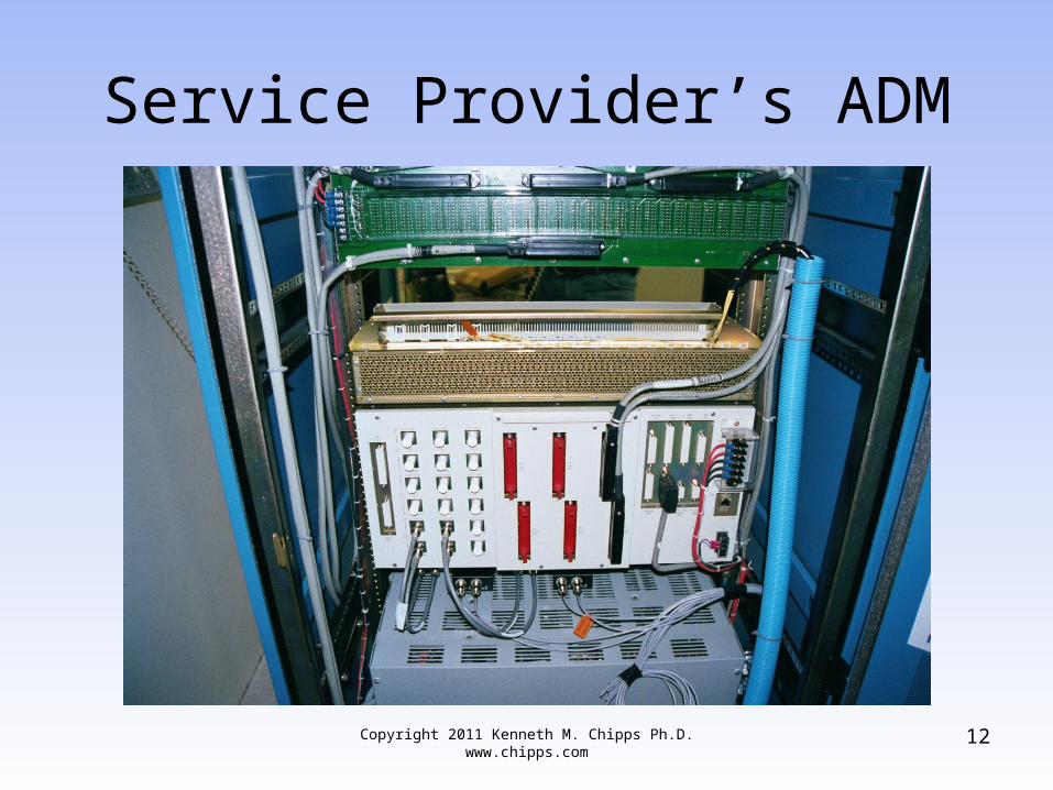
Service Provider’s ADM
Copyright 2011 Kenneth M. Chipps Ph.D. www.chipps.com 12
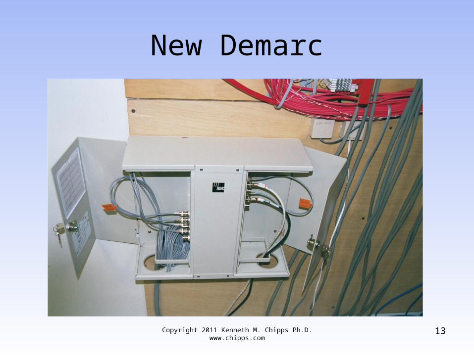
New Demarc
Copyright 2011 Kenneth M. Chipps Ph.D. www.chipps.com 13
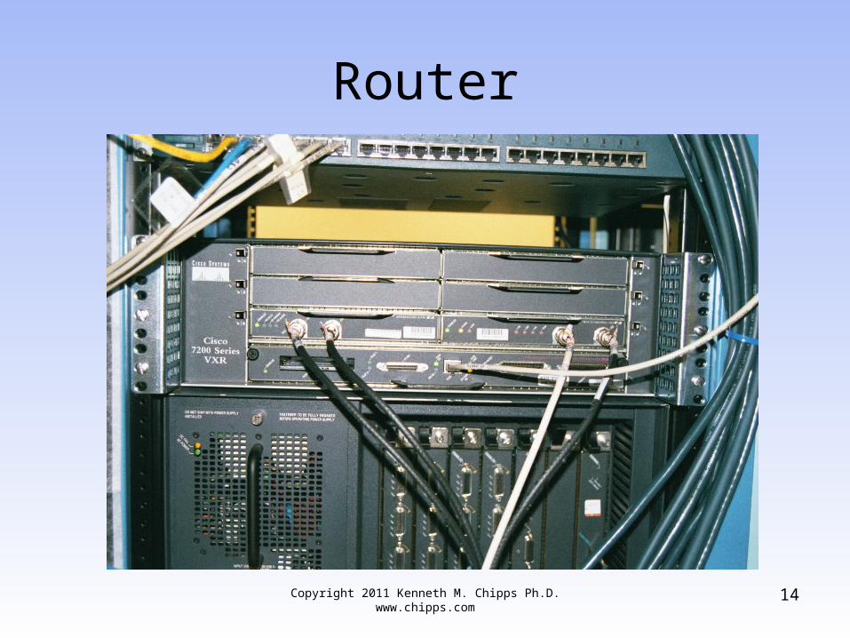
Router
Copyright 2011 Kenneth M. Chipps Ph.D. www.chipps.com 14
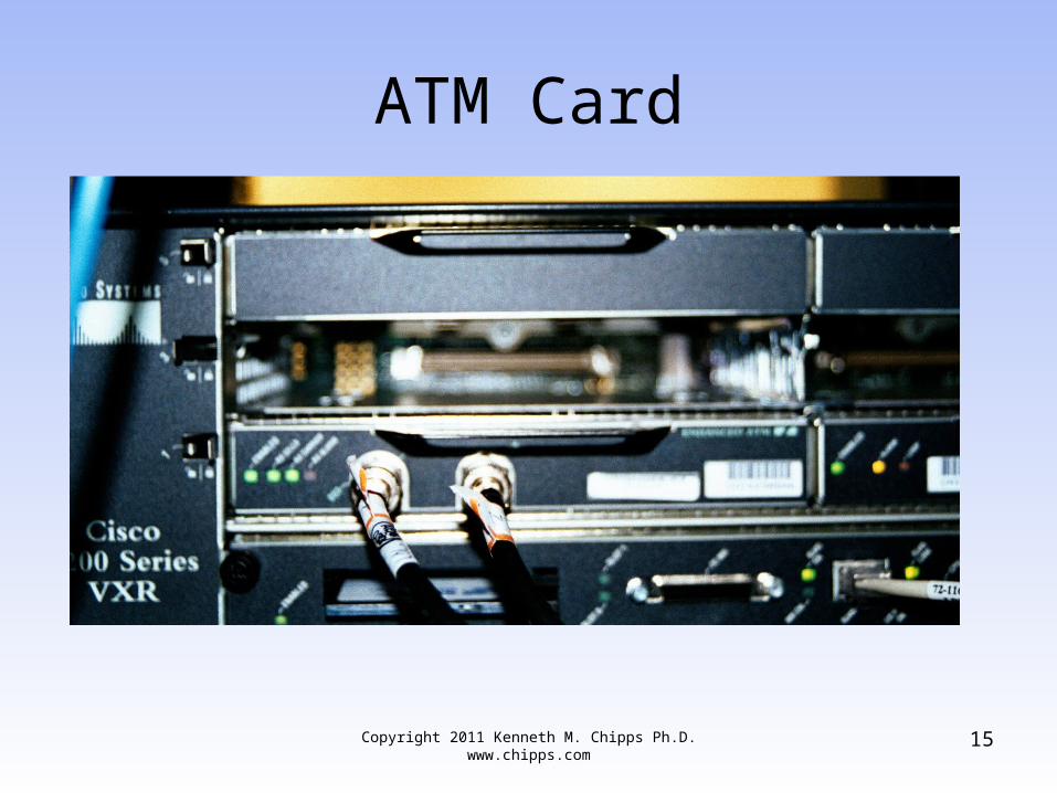
ATM Card
Copyright 2011 Kenneth M. Chipps Ph.D. www.chipps.com 15
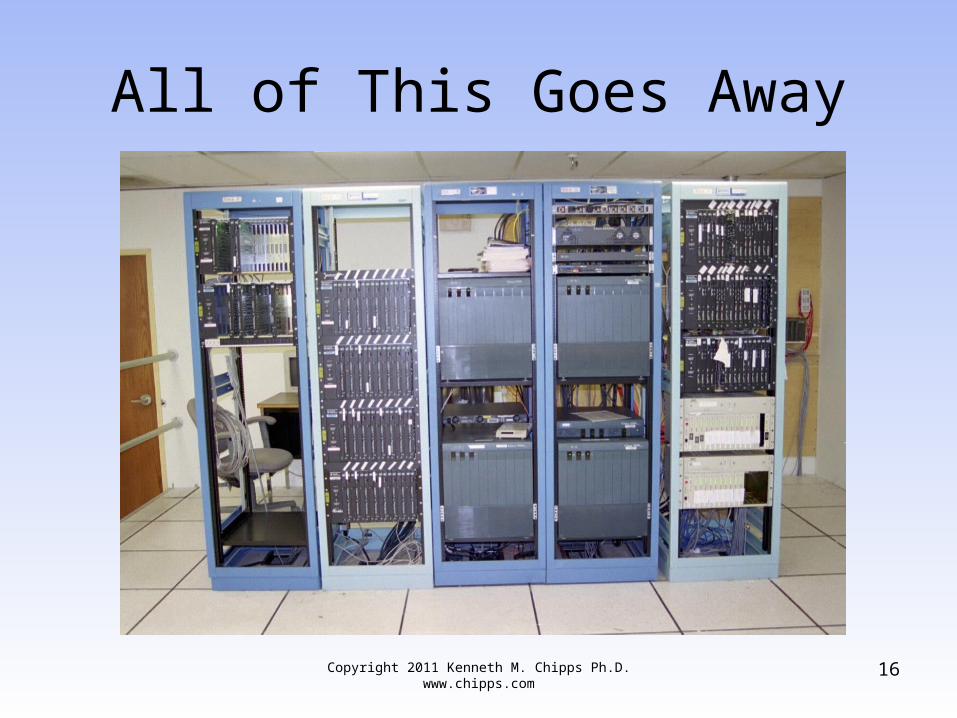
All of This Goes Away
Copyright 2011 Kenneth M. Chipps Ph.D. www.chipps.com 16
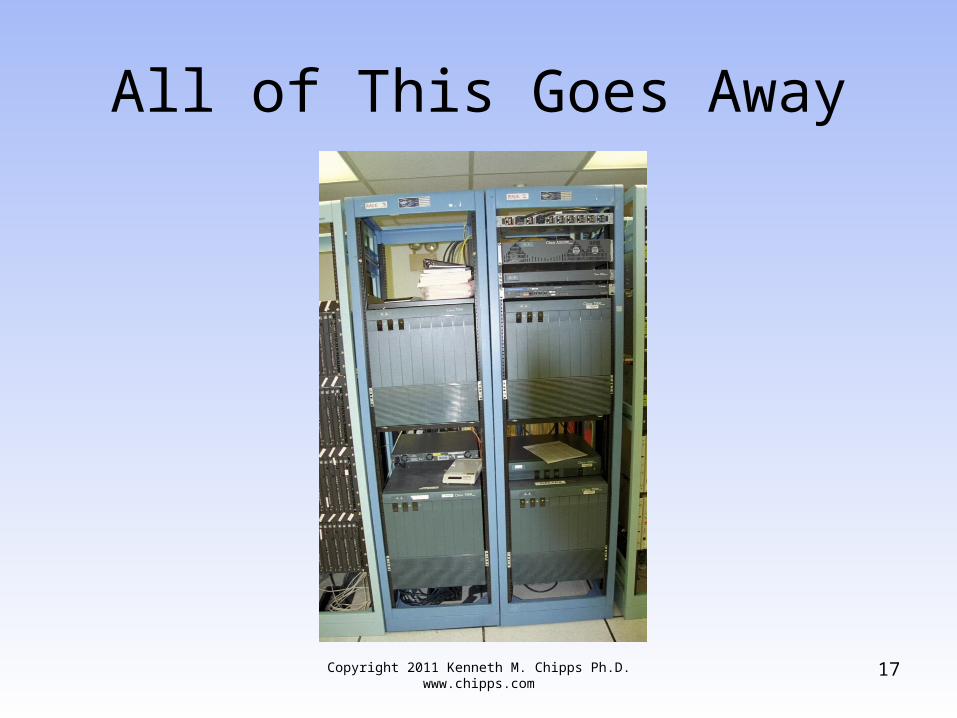
All of This Goes Away
Copyright 2011 Kenneth M. Chipps Ph.D. www.chipps.com 17
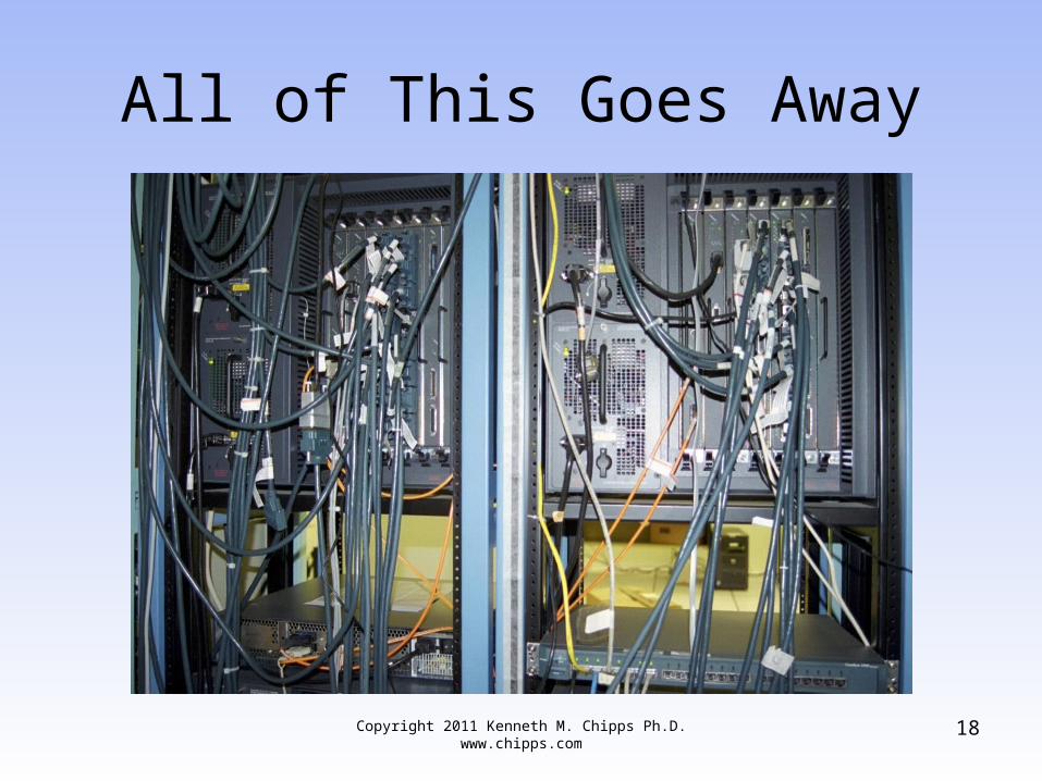
All of This Goes Away
Copyright 2011 Kenneth M. Chipps Ph.D. www.chipps.com 18
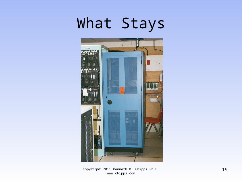
What Stays
Copyright 2011 Kenneth M. Chipps Ph.D. www.chipps.com 19
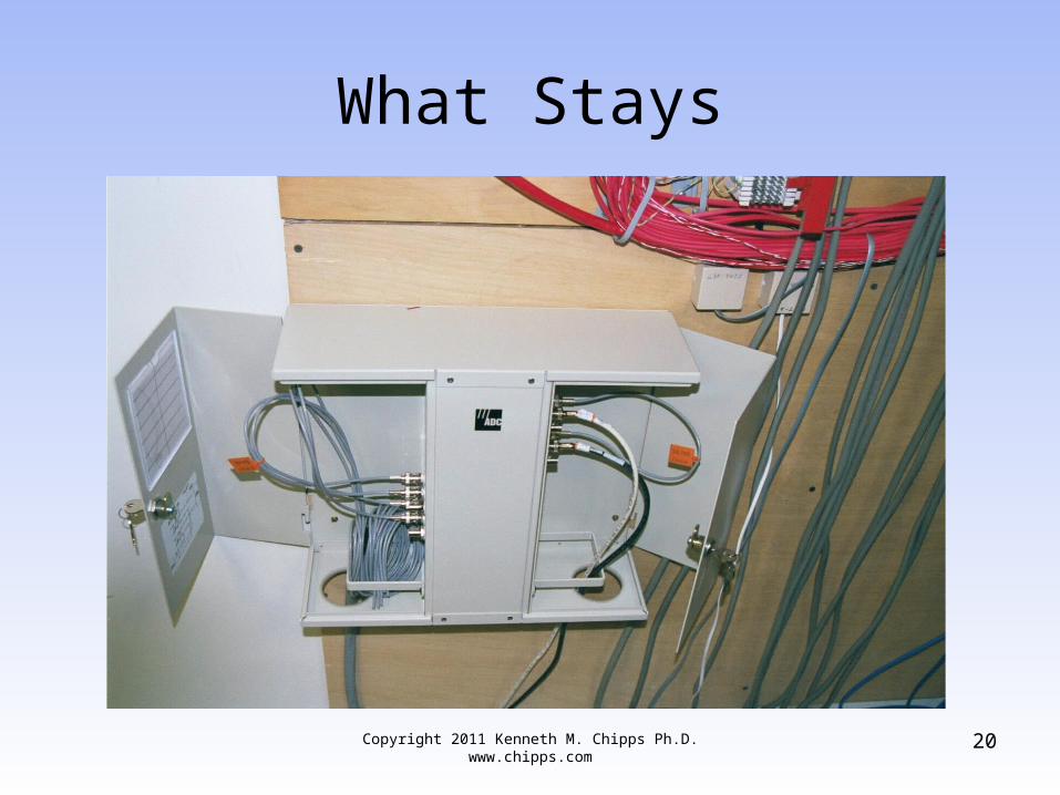
What Stays
Copyright 2011 Kenneth M. Chipps Ph.D. www.chipps.com 20
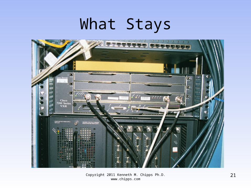
What Stays
Copyright 2011 Kenneth M. Chipps Ph.D. www.chipps.com 21
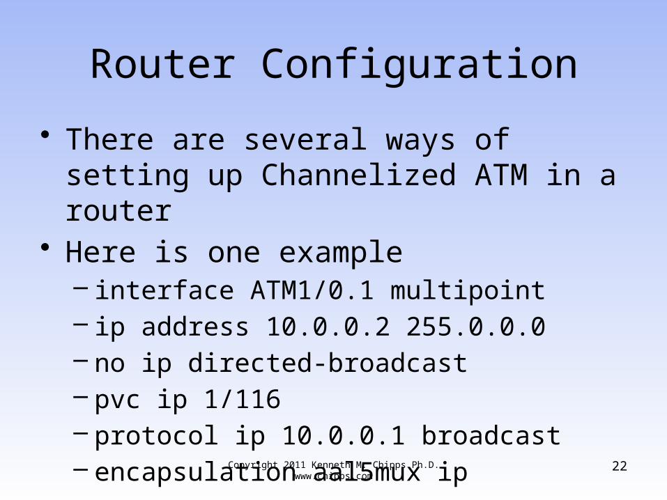
Router Configuration
• There are several ways of setting up Channelized ATM in a router
• Here is one example– interface ATM1/0.1 multipoint– ip address 10.0.0.2 255.0.0.0– no ip directed-broadcast– pvc ip 1/116– protocol ip 10.0.0.1 broadcast– encapsulation aal5mux ip
Copyright 2011 Kenneth M. Chipps Ph.D. www.chipps.com 22
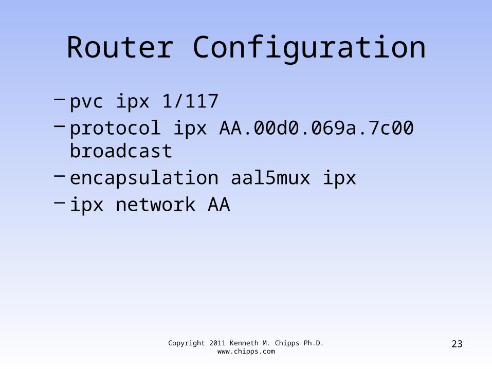
Router Configuration
– pvc ipx 1/117– protocol ipx AA.00d0.069a.7c00 broadcast– encapsulation aal5mux ipx– ipx network AA
Copyright 2011 Kenneth M. Chipps Ph.D. www.chipps.com 23
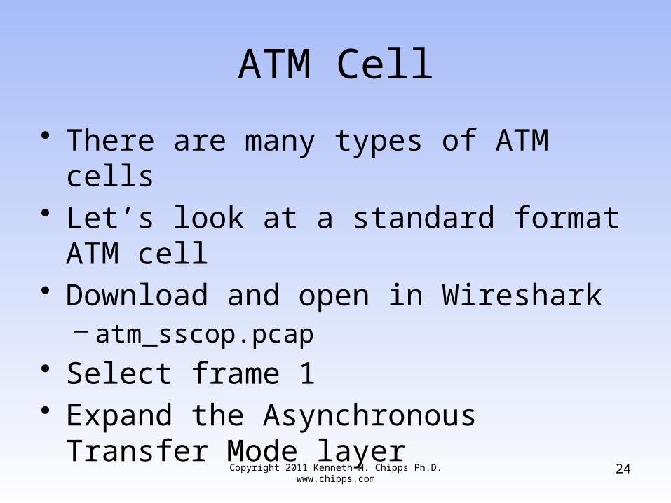
ATM Cell
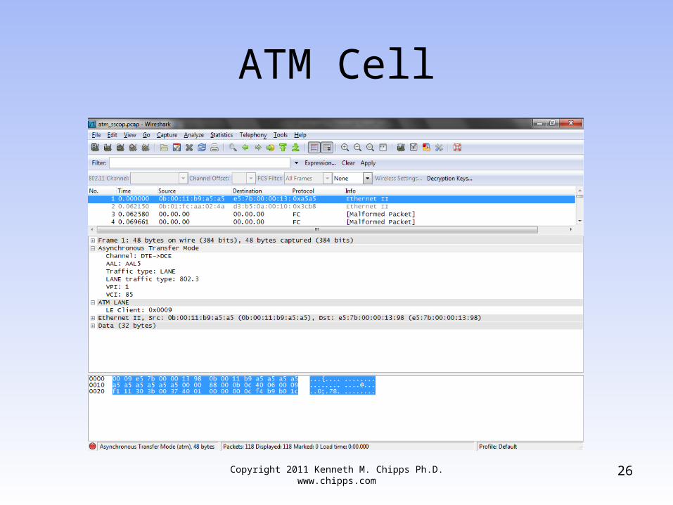
• There are many types of ATM cells• Let’s look at a standard format ATM cell• Download and open in Wireshark
– atm_sscop.pcap• Select frame 1• Expand the Asynchronous Transfer Mode
layer
Copyright 2011 Kenneth M. Chipps Ph.D. www.chipps.com 24
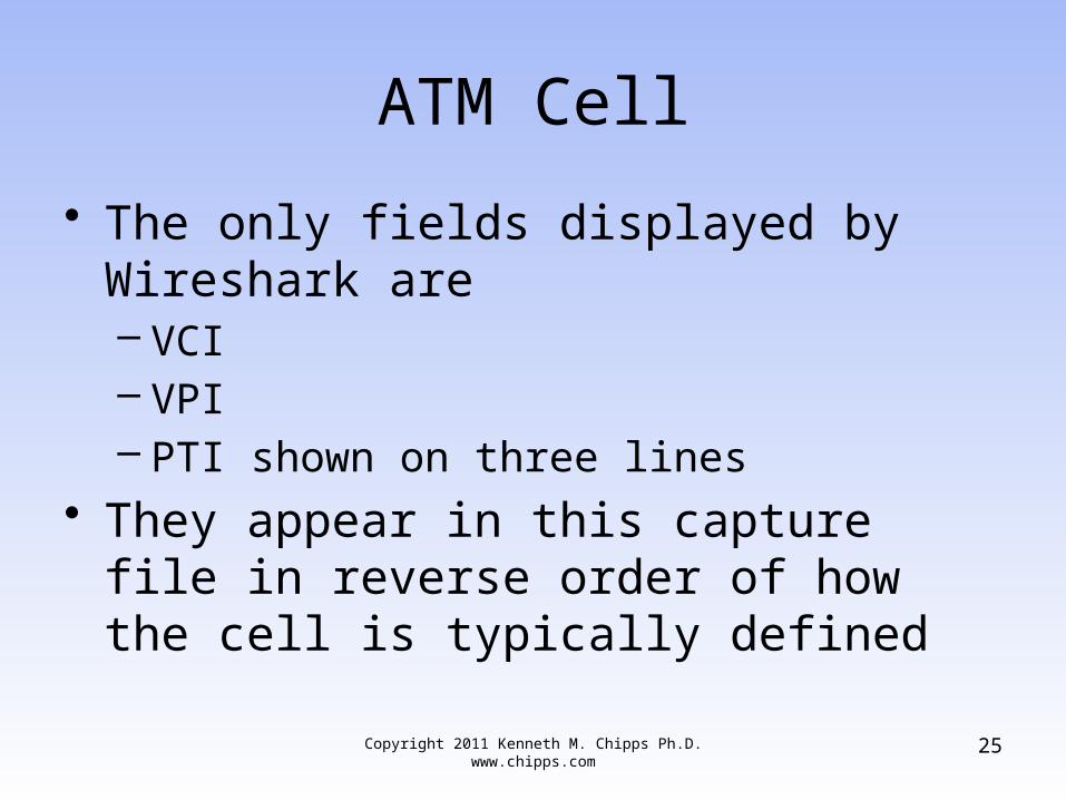
ATM Cell
• The only fields displayed by Wireshark are– VCI– VPI– PTI shown on three lines
• They appear in this capture file in reverse order of how the cell is typically defined
Copyright 2011 Kenneth M. Chipps Ph.D. www.chipps.com 25
ATM Cell
Copyright 2011 Kenneth M. Chipps Ph.D. www.chipps.com 26
ATM Cell
• Here are the fields in an ATM 5 byte header as shown in a discussion on the Microsoft TechNet web site
Copyright 2011 Kenneth M. Chipps Ph.D. www.chipps.com 27
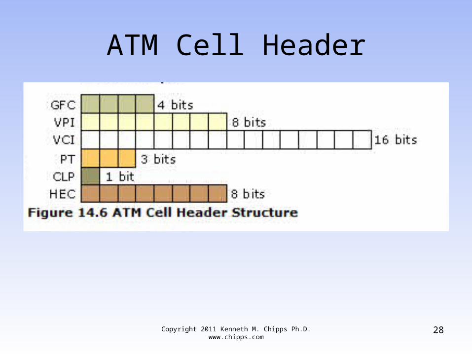
ATM Cell Header
Copyright 2011 Kenneth M. Chipps Ph.D. www.chipps.com 28
GFC Field
• The GFC – Generic Flow Control is 4 bits that was designed for flow control, but was never standardized
• So this field is always set to 0000
Copyright 2011 Kenneth M. Chipps Ph.D. www.chipps.com 29
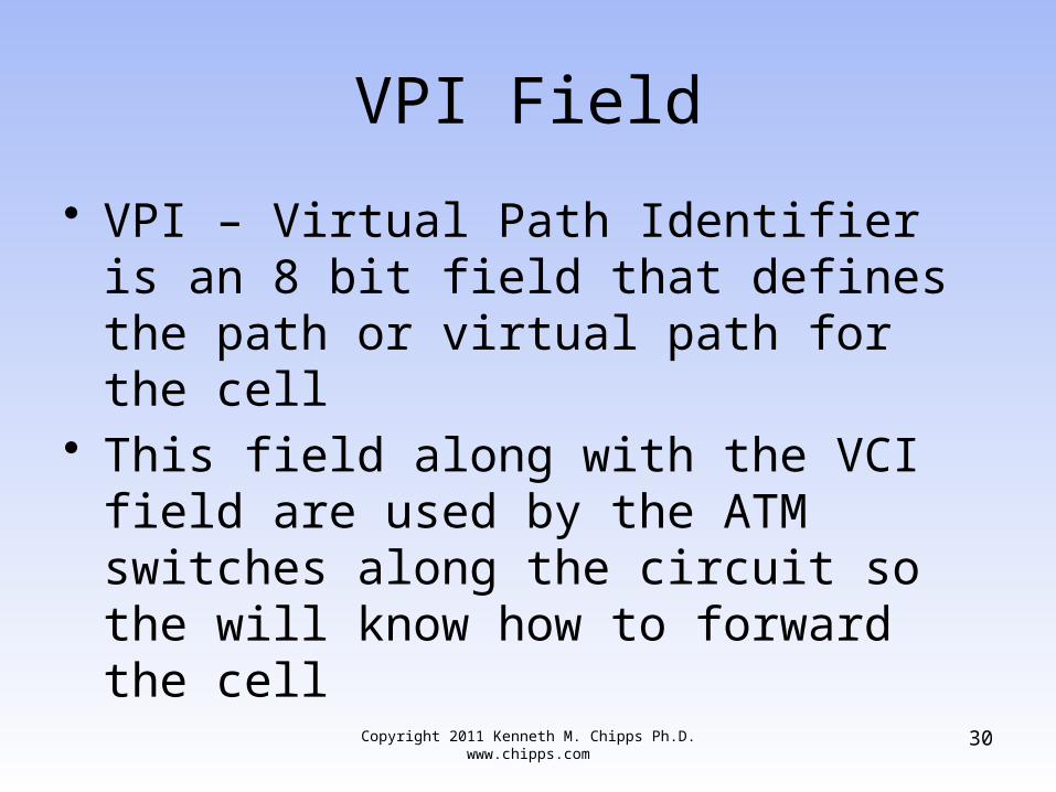
VPI Field
• VPI – Virtual Path Identifier is an 8 bit field that defines the path or virtual path for the cell
• This field along with the VCI field are used by the ATM switches along the circuit so the will know how to forward the cell
Copyright 2011 Kenneth M. Chipps Ph.D. www.chipps.com 30
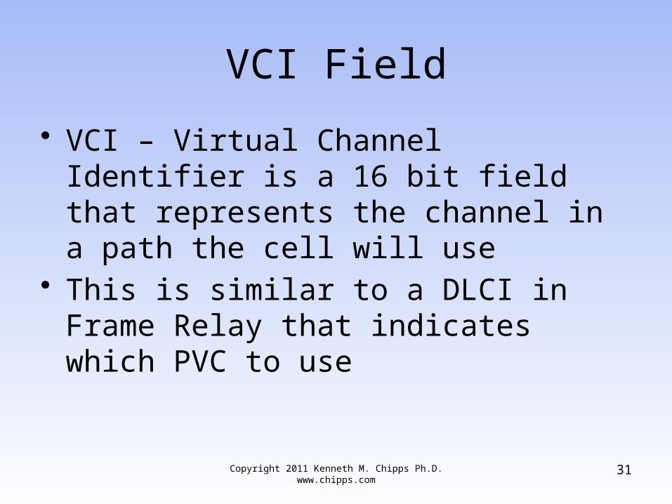
VCI Field
• VCI – Virtual Channel Identifier is a 16 bit field that represents the channel in a path the cell will use
• This is similar to a DLCI in Frame Relay that indicates which PVC to use
Copyright 2011 Kenneth M. Chipps Ph.D. www.chipps.com 31
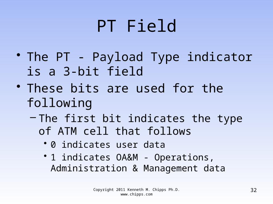
PT Field
• The PT - Payload Type indicator is a 3-bit field
• These bits are used for the following– The first bit indicates the type of ATM cell that
follows• 0 indicates user data• 1 indicates OA&M - Operations, Administration &
Management data
Copyright 2011 Kenneth M. Chipps Ph.D. www.chipps.com 32
PT Field
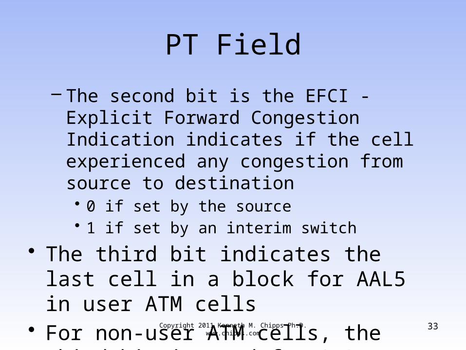
– The second bit is the EFCI - Explicit Forward Congestion Indication indicates if the cell experienced any congestion from source to destination• 0 if set by the source• 1 if set by an interim switch
• The third bit indicates the last cell in a block for AAL5 in user ATM cells
• For non-user ATM cells, the third bit is used for OA&M functions
Copyright 2011 Kenneth M. Chipps Ph.D. www.chipps.com 33
CLP Field
• The CLP - Cell Loss Priority field is a 1-bit field to tell the forwarding switches what priority to give to the cell• 0 is high priority• Switches must make every effort to forward
the cell successfully• 1 means the switch may discard the cell if
congestion warrants it like the DE - Discard Eligibility bit in Frame Relay
Copyright 2011 Kenneth M. Chipps Ph.D. www.chipps.com 34
HEC Field
• The HEC – Header Checksum Field is an 8 bit field
• This is the checksum to ensure the cell header arrived undamaged
• It relies on the upper layers to check the data
• A single bit error can be repaired• A multi-bit error calls for it to be discarded
Copyright 2011 Kenneth M. Chipps Ph.D. www.chipps.com 35
ATM Cell
• Now let’s look at another type of ATM cell such as would be used in a CAN
• ATM CAN links and ATM in the LAN to the extent it ever migrated that far used a different format for their cells
• These are the AAL5 cells used to send data over these local as opposed to long distance service provider networks that use the standard 53 byte cell
Copyright 2011 Kenneth M. Chipps Ph.D. www.chipps.com 36
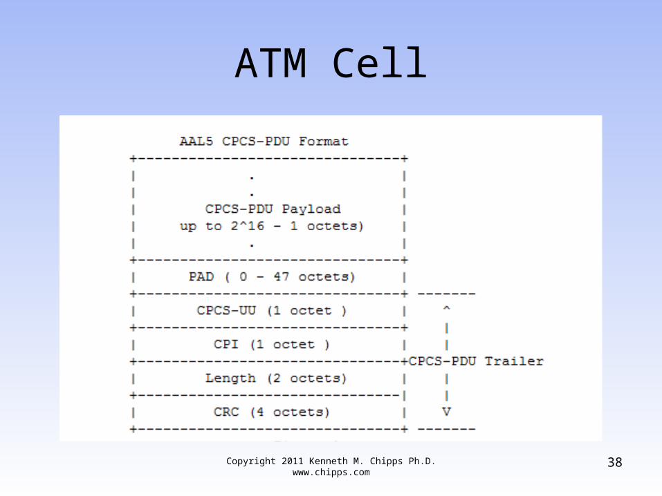
ATM Cell
• The format of these cells is defined in RFC 2364
• As it says– ATM AAL5 protocol is designed to provide
virtual connections between end stations attached to the same network
• Here is the format of these cells
Copyright 2011 Kenneth M. Chipps Ph.D. www.chipps.com 37
ATM Cell
Copyright 2011 Kenneth M. Chipps Ph.D. www.chipps.com 38

ATM Cell
• Notice that in this cell the header has become a trailer
Copyright 2011 Kenneth M. Chipps Ph.D. www.chipps.com 39
ATM Cell
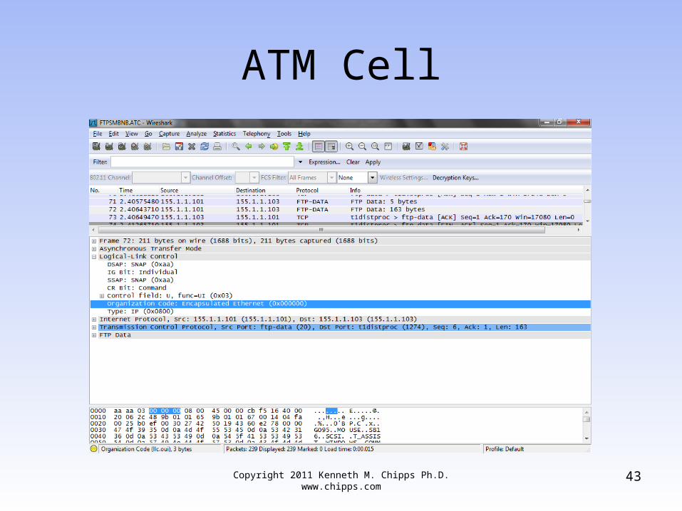
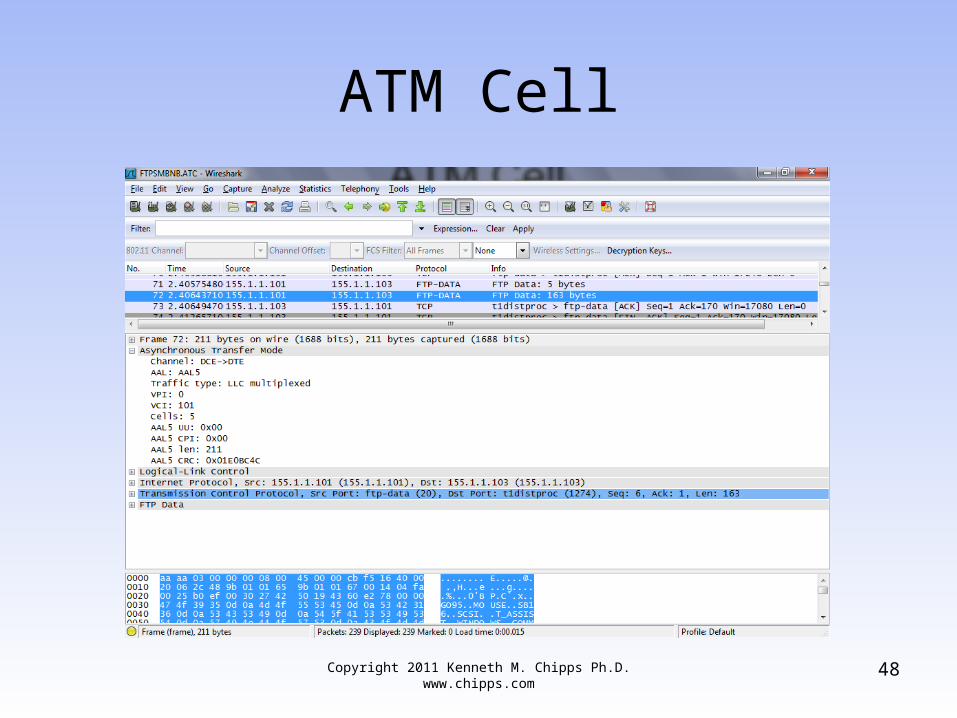
• Let’s look at an example of a real cell in this format
• Download and open in Wireshark– ftpsmbnb.atc
• Select frame 72• This is a ftp data frame where a file is
being retrieved from a FTP server by a client
Copyright 2011 Kenneth M. Chipps Ph.D. www.chipps.com 40
ATM Cell
• Notice how the common LAN layers of– LLC– IP– TCP– FTP
• are all present• The difference is the data link
transportation is being done over ATM as the first layer shows
Copyright 2011 Kenneth M. Chipps Ph.D. www.chipps.com 41
ATM Cell
• The physical layer is likely some form of fiber optic cable, although we cannot tell from the capture file
• Expand the LLC layer• Notice that is carrying encapsulated
Ethernet
Copyright 2011 Kenneth M. Chipps Ph.D. www.chipps.com 42
ATM Cell
Copyright 2011 Kenneth M. Chipps Ph.D. www.chipps.com 43
ATM Cell
• Expand the Asynchronous Transfer Mode layer
• From bottom to top we see these fields– CRC
• The error free transmission verification normally seen in a trailer
– Len• This field indicates the length in octets of the
Payload field• The maximum value for this field is 65535 octets
Copyright 2011 Kenneth M. Chipps Ph.D. www.chipps.com 44
ATM Cell
– CPI• This field is not normally used• The RFC says this about it
– The CPI (Common Part Indicator) field aligns the CPCS-PDU trailer to 64 bits
– Possible additional functions are for further study in ITU-T
– When only the 64 bit alignment function is used, this field shall be coded as 0x00
Copyright 2011 Kenneth M. Chipps Ph.D. www.chipps.com 45
ATM Cell
– UU• This field is always set to zero zero since as the
RFC says– The CPCS-UU (User-to-User indication) field is used to
transparently transfer CPCS user to user information– The field has no function under the multi-protocol ATM
encapsulation described in this memo and can be set to any value
Copyright 2011 Kenneth M. Chipps Ph.D. www.chipps.com 46
ATM Cell
• Above these fields we see the usual VCI and VPI fields to indicate the channel and path for the cells and that this is a AAL5 format cell
Copyright 2011 Kenneth M. Chipps Ph.D. www.chipps.com 47
ATM Cell
Copyright 2011 Kenneth M. Chipps Ph.D. www.chipps.com 48
ATM Cell
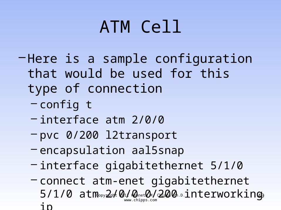
–Here is a sample configuration that would be used for this type of connection– config t – interface atm 2/0/0 – pvc 0/200 l2transport – encapsulation aal5snap – interface gigabitethernet 5/1/0 – connect atm-enet gigabitethernet 5/1/0 atm
2/0/0 0/200 interworking ipCopyright 2011 Kenneth M. Chipps Ph.D. www.chipps.com 49


