
Audi Vorsprung durch Technik
AudiService Training
Audi A8 ’10 Power Transmission
Eight-speed Automatic Gearboxes 0BK and 0BLRear Axle Drives 0BF and 0BE – Sport Differential
All rights reserved. Technical
specifications subject to change
without notice.
Copyright
AUDI AG
I/VK-35
AUDI AG
D-85045 Ingolstadt
Technischer Stand 11/09
Printed in Germany
A10.5S00.61.20
Self-Study Programme 457
45
7
The world of Audi gearboxes
With the innovative new developments in the field of power trans-
mission, such as the multitronic gearbox and the dual-clutch gear-
box, Volkswagen and Audi have radically revised the requirements
profile for modern multistep automatic gearboxes.
In addition to better fuel economy, now a major issue in view of
the ongoing debate on CO2 emissions, both dynamics and respon-
siveness top the list of requirements for sporty premium vehicles.
These demands have already been satisfied with the launch of the
second-generation six-speed automatic gearboxes by ZF Getriebe
GmbH (refer to Self-Study Programme 385 covering the 0B6 gear-
box).
Vibration damping has been improved with the help of new torque
converters, giving better fuel economy and a more direct driving
feel. Thanks to neutral idle control, which reduces torque input
when the vehicle is stationary with the foot brake applied, and a
marked reduction in shift and reaction times, the user-friendly
automatic torque converters have evolved into modern, highly
efficient sport gearboxes.
"When developing the new automatic gearbox we did not focus on
the number of gears, but on markedly improved fuel economy and
enhanced performance."
Dr. Michael Paul,
Board Member with responsibility for Technology,
ZF Friedrichshafen AG
A detailed system analysis carried out by ZF Getriebe GmbH has
shown that the ever-growing list of customer wishes can no longer
be satisfied by further enhancement of the existing six-speed auto-
matic gearboxes. For this reason, a gearbox series based on an
entirely new gearbox concept has been developed for the new
Audi A8 ’10 in collaboration with ZF Getriebe GmbH.
The main focus of development was on:
• better fuel economy with reduced RPM and drag losses
• improved performance with shorter gear steps, multiple direct
shifts and a low power-to-weight ratio
• design flexibility in the interior through the use of a shift-by-wire
concept
These development efforts are reflected in the new eight-speed
automatic gearboxes 0BK and 0BL.

3
457_007
- 6 %
- 2 %
- 5 %
- 3 %
- 6 %
- 5 %1)
457_006
The higher fuel efficiency of the 8HP automatic gearbox genera-
tion is due to the following modifications:
• a wider ratio spread and more gears for better adaptation to
ideal engine operating points
• significantly reduced drag torque in the shift elements
(only two open shift elements per gear)
• use of a more efficient ATF pump (twin-stroke vane pump)
• improved torsion damping in the converter
Improving the fuel efficiency of ZF automatic gearboxes
Three-speed Four-speed Five-speed Second-genera-
tion six-speed
Eight-speedFirst-genera-
tion six-speed
Another potentially effective way of improving fuel efficiency is to
eliminate idling fuel consumption in the internal combustion
engine while the vehicle is at a standstill. This has a very positive
impact in city traffic.
To exploit this potential, the 3.0 V6 TDI uses the start-stop
function in combination with an automatic gearbox for the first
time. Other applications are currently being developed.
1) Potential fuel savings in start-stop mode as determined in
NEDC simulations (New European Driving Cycle)

4
Power transmission in the Audi A8 ’10New features at a glance __________________________________________________________________________________________________________________________ 6
shift-by-wire shift control systemIntroduction ________________________________________________________________________________________________________________________________________ 8
tiptronic function___________________________________________________________________________________________________________________________________ 8
Features of the shift control system _____________________________________________________________________________________________________________ 9
Operating concept_________________________________________________________________________________________________________________________________10
Shift schematic – function________________________________________________________________________________________________________________________11
Selector lever sensors control unit J587 ________________________________________________________________________________________________________12
Selector lever position sensor G727_____________________________________________________________________________________________________________12
Functions, networking and interfaces___________________________________________________________________________________________________________13
Gear knob/selector lever release button E681 _________________________________________________________________________________________________14
Selector lever position indicator unit Y26 ______________________________________________________________________________________________________14
Function diagram – selector lever E313_________________________________________________________________________________________________________15
Gearshift indicators _______________________________________________________________________________________________________________________________15
shift-by-wire functions/operation _______________________________________________________________________________________________________________16
Auto P function (automatic parking lock)_______________________________________________________________________________________________________16
Emergency release device for the parking lock _________________________________________________________________________________________________18
Eight-speed automatic gearbox 0BK/0BLIntroduction _______________________________________________________________________________________________________________________________________20
Specifications ______________________________________________________________________________________________________________________________________21
Special and common features at a glance ______________________________________________________________________________________________________22
Splined prop shaft_________________________________________________________________________________________________________________________________23
Centre differential_________________________________________________________________________________________________________________________________23
Torque converter __________________________________________________________________________________________________________________________________24
ATF supply/ATF pump_____________________________________________________________________________________________________________________________25
ATF (Automatic Transmission Fluid)_____________________________________________________________________________________________________________25
Planetary gearbox _________________________________________________________________________________________________________________________________26
Shift elements _____________________________________________________________________________________________________________________________________26
Brakes ______________________________________________________________________________________________________________________________________________27
Clutches ____________________________________________________________________________________________________________________________________________27
Shift schematic/shift matrix _____________________________________________________________________________________________________________________28
Description of gears – torque characteristic ____________________________________________________________________________________________________29
Sectional view of 0BK gearbox ___________________________________________________________________________________________________________________32
Oil system/lubrication/sealing of 0BK gearbox ________________________________________________________________________________________________34
Separate oil systems ______________________________________________________________________________________________________________________________34
Common oil system _______________________________________________________________________________________________________________________________35
Oil system/lubrication/sealing of 0BL gearbox ________________________________________________________________________________________________36
Gear oil system (common oil system) ___________________________________________________________________________________________________________36
Common oil system – gear oil circuit ____________________________________________________________________________________________________________37
Innovative Thermal Management (ITM) ________________________________________________________________________________________________________38
Gearbox heating/cooling – V8 FSI engine_______________________________________________________________________________________________________38
Gearbox heating/cooling – V8 TDI engine ______________________________________________________________________________________________________40
Mechatronics – electro-hydraulic control system ______________________________________________________________________________________________42
Mechatronics/automatic gearbox control unit J217___________________________________________________________________________________________43
Mechatronics – actuators _________________________________________________________________________________________________________________________44
Pressure regulating valves – solenoid valves ___________________________________________________________________________________________________44
Hydraulic interfaces _______________________________________________________________________________________________________________________________45
Monitoring of temperature in J217______________________________________________________________________________________________________________46
Mechatronics – sensors ___________________________________________________________________________________________________________________________47
Gearbox input speed sender G182_______________________________________________________________________________________________________________47
Gearbox output speed sender G195_____________________________________________________________________________________________________________47
Parking lock ________________________________________________________________________________________________________________________________________48
Parking lock – function____________________________________________________________________________________________________________________________48
Parking lock – limp-home functions _____________________________________________________________________________________________________________50
Parking lock sender G747 ________________________________________________________________________________________________________________________51
Contents
Functions – neutral idle __________________________________________________________________________________________________________________________ 52
Functions – gearbox adaption ___________________________________________________________________________________________________________________ 53
Functions – start-stop system ___________________________________________________________________________________________________________________ 54
Hydraulic Impulse Storage – HIS ________________________________________________________________________________________________________________ 54
Start-stop mode __________________________________________________________________________________________________________________________________ 56
Functions – navigation-based gear selection___________________________________________________________________________________________________ 58
Functions – displays/warnings___________________________________________________________________________________________________________________ 62
Functions – special feature of adaptive cruise control (ACC) mode__________________________________________________________________________ 63
Functions – encoding the automatic gearbox control unit J217 _____________________________________________________________________________ 63
Functions – adapting the gear indicator ________________________________________________________________________________________________________ 63
Functions – limp-home programs and substitute programs _________________________________________________________________________________ 63
Towing _____________________________________________________________________________________________________________________________________________ 63
Rear axle drive 0BC/0BF/0BEConventional rear axle drive/sport differential _______________________________________________________________________________________________ 64
Rear axle drive 0BE/sport differential __________________________________________________________________________________________________________ 65
Intelligent torque distribution __________________________________________________________________________________________________________________ 66
Self-Study Programmes relevant to the Audi A8 ’10__________________________________________________________________________________________ 67
• The Self-Study Programme teaches the basics of the design and function of new models, automotive
components or technologies.
It is not a Repair Manual. Figures given are for guidance purposes only and refer to the software version
valid at the time of preparation of the SSP.
For further information about maintenance and repair work, always refer to the current technical literature.
!Reference
Note
5
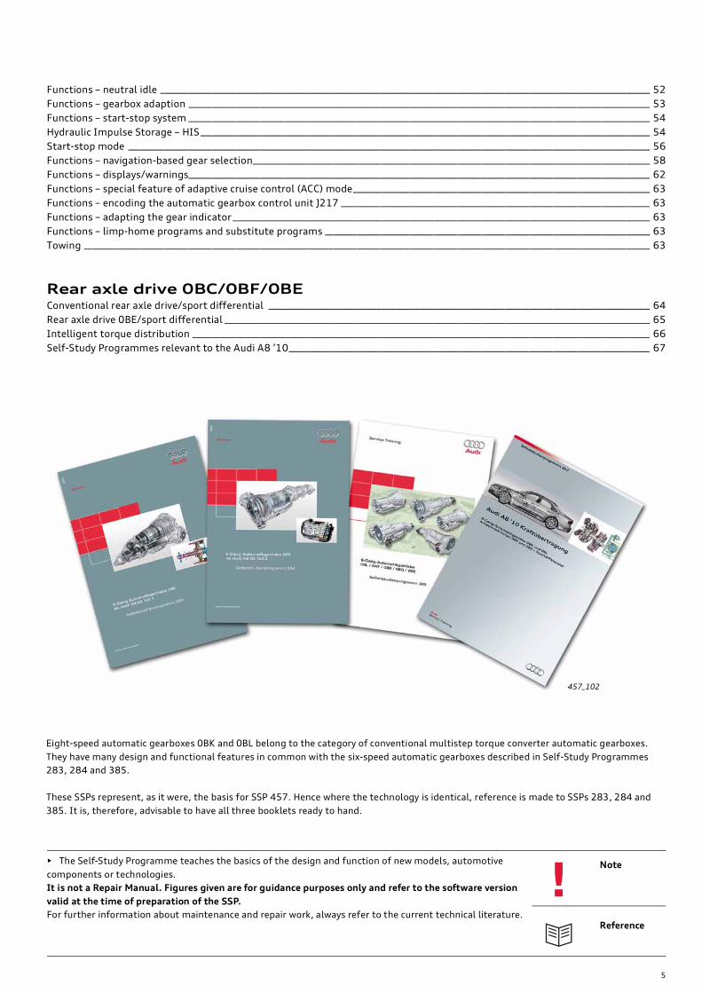
Eight-speed automatic gearboxes 0BK and 0BL belong to the category of conventional multistep torque converter automatic gearboxes.
They have many design and functional features in common with the six-speed automatic gearboxes described in Self-Study Programmes
283, 284 and 385.
These SSPs represent, as it were, the basis for SSP 457. Hence where the technology is identical, reference is made to SSPs 283, 284 and
385. It is, therefore, advisable to have all three booklets ready to hand.
457_102

6
Power transmission in the Audi A8 ’10
457_043
New features at a glance
The drive concept with set-back engine-gearbox layout was previ-
ously implemented in the Audi A8 ’03. The Audi A8 ’03 therefore
pioneered the concept of setting forward the centre of the front
axle, later improved in the B8 series. This new engine-gearbox
layout is now also the basis for the Audi A8 ’10.
The new eight-speed automatic gearboxes are without doubt one
of the highlights. They take the Audi A8 ’10 into a new dimension
in driving dynamics, comfort and efficiency.
In conjunction with the latest generation of the quattro all-wheel
drive system, these gearboxes provide a maximum in driving
dynamics. The Audi A8 ’10 will be available exclusively with
quattro drive at market launch and later.
To include a model optimised for fuel economy in this vehicle class,
a version with front-wheel drive is planned.Two newly developed automatic gearboxes:
Eight-speed automatic gearbox 0BK for all engine
versions except 4.2l TDI
Eight-speed automatic gearbox 0BL (for 4.2l TDI only) –
exclusively available with quattro drive
Other new features/special features:
– shift-by-wire shift control system
– with start-stop application
Depending on engine version, the following differen-
tials are used:
– Rear axle drive 0BC (all engines except 4.2l TDI)
– Rear axle drive 0BF, sport differential
(optional, all engines except 4.2l TDI)
– Rear axle drive 0BE, sport differential (available with
4.2l TDI only, standard)
New, higher-torque sport differential 0BE for 4.2l TDI
engine (standard); the sport differential 0BF is option-
ally available in combination with other engine versions
(refer to page 64).
Axle flange with new sealing and assembly
concept (as in the B8 series)
(refer to Self-Study Programme 409, page 30 ff.).

7
457_001
Set-forward axle gear (as in the B8 series)
(refer to Self-Study Programmes 392 and 409)
quattro with asymmetrical/dynamic torque split and intelligent
torque distribution
For information about the intelligent torque distribution system
(refer to page 66).
Splined prop shaft – weight has been significantly reduced by
eliminating the screw flange coupling (refer to page 23)
Reference
The drive concept of the Audi A8 ’10 is identical to that of the B8 series (Audi A4/A5) in several respects.
A large amount of information, to which reference is made in this booklet, has been previously published in Self-Study Pro-
grammes 392 and 409.
Other special features of the power transmission system in the Audi A5 were presented in the Audi iTV broadcast of
04.07.2007. The information relating to the axle configuration equally applies to the Audi A8 ’10 and represents a basic
knowledge of this subject.
8
Advantages of the "full" shift-by-wire concept
• new scope for configuring the shift control system, e.g. design,
size, positioning in vehicle and operating concept
• scope for new comfort and safety functions, e.g. automatic park-
ing lock engagement
• simplified assembly of the shift control system and gearbox, no
setting work required
• improved acoustics in the vehicle interior by separation of the
shift control system and gearbox1)
Introduction
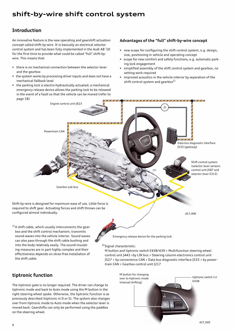
An innovative feature is the new operating and gearshift actuation
concept called shift-by-wire. It is basically an electrical selector
control system and has been fully implemented in the Audi A8 ’10
for the first time to provide what could be called "full" shift-by-
wire. This means that:
• there is no mechanical connection between the selector lever
and the gearbox
• the system works by processing driver inputs and does not have a
mechanical fallback level
• the parking lock is electro-hydraulically actuated; a mechanical
emergency release device allows the parking lock to be released
in the event of a fault so that the vehicle can be moved (refer to
page 18)
2)
457_008
shift-by-wire shift control system
457_009
Powertrain CAN
Engine control unit J623
Gearbox sub-bus
Shift control system
(selector lever sensors
control unit J587 and
selector lever E313)
Data bus diagnostic interface
J533 (gateway)
Shift-by-wire is designed for maximum ease of use. Little force is
required to shift gear. Actuating forces and shift throws can be
configured almost individually.
1)A shift cable, which usually interconnects the gear-
box and the shift control mechanism, transmits
sound waves into the vehicle interior. Sound waves
can also pass through the shift cable bushing and
into the body relatively easily. The sound-insulat-
ing measures are in part highly complex and their
effectiveness depends on stree-free installation of
the shift cable.
Emergency release device for the parking lock
tiptronic function
The tiptronic gate is no longer required. The driver can change to
tiptronic mode and back to Auto mode using the M button in the
right steering wheel spoke. Otherwise, the tiptronic function is as
previously described (tiptronic in D or S). The system also changes
over from tiptronic mode to Auto mode when the selector lever is
moved back. Gearshifts can only be performed using the paddles
on the steering wheel.
2)Signal characteristic:
M button and tiptronic switch E438/439 > Multifunction steering wheel
control unit J443 >by LIN bus > Steering column electronics control unit
J527 > by convenience CAN > Data bus diagnostic interface J533 > by power-
train CAN > Gearbox control unit J217
M button for changing
over to tiptronic mode
(manual shifting)
tiptronic switch (+)
E438

9
Features of the shift control system
The new design and operating concept of the shift control system
are an innovation. The overview shows you the components, spe-
cial features and innovations in summary form.
457_010
Integrated selector lever position indicator unit
(gear) Y26.
It indicates the currently selected gear (not the
selector lever position).
Selector lever release button E681
(electrical switch), replaces the previ-
ously known mechanical locking and
release mechanism used for shifting in
and out of certain gears.
Intuitive operating logic, selector
returns automatically to centre position.
Short throw shifting for maximum ease
of use (max. travel 23 mm).
Selector lever travel is dependent on the
current gear, maximum 3 positions for-
wards and 3 back (refer to page 11).
Ergonomic selector lever in "yacht lever design"
with various applications in leather or wood.
The "yacht lever" serves as a comfortable
handrest and makes the MMI input unit easier
to operate (in the Audi A8 ’10 the MMI is
located in front of the shift controls).
Shift control without tiptronic selector gate,
tiptronic mode can be selected using the M
button in the right steering wheel spoke
(refer to page 8).
Separate control unit with integrated sensors
for selector lever movement and position
recognition.
The system communicates with the gearbox
control unit via the local CAN bus
(refer to page 13).
12-way plug-in connector from
selector lever control unit to
gear knob
Easy assembly of the shift control by means of centring pins on the housing.
If the shift control does not fit despite centring, the centring pins can be cut
off and the shift control aligned within the hole clearance.
Conductor strip
Shift mechanism with locking device
and 5 locking solenoids.
Movement of the selector lever
(forwards or back) is limited according to
gear by means of multiple locking
solenoids in lieu of a shift gate.
In addition, shift-locking is implemented
in the P and N positions by means of
locking solenoids (refer to page 11).
Selector gate cover/masking
panel, with flexible mounting
for self-centring with respect
to the console

10
Operating concept
The shift-by-wire shift control of the Audi A8 ’10 is not only a
visually striking feature, but is also an innovation in terms of its
operation and function.
The shift-by-wire concept has made possible a new shift control
design. Another new aspect is that the selector lever does not, as
previously, follow a shift gate depending on what gear is selected,
but always returns to its original position (normal position) in
much the same way as a joystick.
This means that the selector lever position and the gear or func-
tion mode do not match up like before.
For example: the gearbox is in the "Park" position (P), but the
selector lever is in its normal position.
To avoid confusion between the terms "selector lever position",
"gear" and "function mode", we call this normal position "X".
A logical operating concept was developed so that the shift con-
trol can be operated comfortably and intuitively.
From its normal position "X", the selector lever has three positions
forward and three positions back. The locking device applies
defined actuating forces and provides short, precise shift throws.
Five locking solenoids suppress illogical selector lever movements
and make for logical and intuitive operation.
For example: If the gearbox is in "Park", the selector lever cannot
be moved forward but can be moved up to 3 positions back, e. g.
when the driver wants to shift from P to D (1st step P > R, 2nd step
R > N, 3rd step N > D). This corresponds to the actuation logic of a
conventional shift control system.
457_011
X = normal position
Locking lever
Selector gate
Shift lock
1) The N lock is active approx. 1 second after "N" is
selected.
For the following gearshifts, the button must be pushed and/or
the foot brake applied:
P > button and foot brake
R > P button
N > D foot brake1)
D/S > N button
N > R button and foot brake1)

11
As before, the unlock button must be pushed and/or the foot
brake applied to shift out of certain gears, e.g. the button must be
pushed and the foot brake applied when shifting out of "P".
Shift schematic – function
As mentioned, the shift movements of the selector lever are
limited by 5 locking solenoids, resulting in logical and intuitive
operation for the driver.
The locking solenoids are activated by the selector lever sensors
control unit J587 in accordance with the selected gear.
457_012
457_013 457_014
Stop damping
Stop damper
Selector lever pivot
Stop damper
Direction of travel
M1 Selector lever lock solenoid 1 N496
M2 Selector lever lock solenoid 2 N497
M3 Selector lever lock solenoid 3 N498
M4 Selector lever lock solenoid 4 N499
M5 Selector lever lock solenoid 5 N500
M1 suppresses shift movements to A2 and A3
(only A1 is enabled)
M2 suppresses shift movements to B2 and B3
(only B1 is enabled)
M3 + M5 lock the selector lever in normal position X
(with P lock and N lock)
M4 suppresses shift movements to A3 and B3
(A1, A2 and B1, B2 are enabled)
M5 + M3 lock the selector lever in normal position X
(with P lock and N lock)Shift schematic
Possible shift movements forward 1)
Range of movement
max. 3 slots forwards
Normal position
Range of movement
max. 3 slots back
Selected gear
Selector lever position
Possible shift movements back 1) Mode changeover 2)
1) Gears can be selected either by repeatedly flicking the selector lever
slot by slot in the desired direction or directly by moving the selector
lever up to three slots (as per the previous operating logic).
2) The S gear can be selected from gear D. To change from D to S or from
S to D, select B1 (pull selector lever 1 notch back).
If the "dynamic" mode is selected with "Audi drive select", "S" is auto-
matically engaged.

12
The selector lever sensors control unit J587 forms a functional unit
together with the selector lever position sensor G727. This func-
tional unit is responsible for detecting driver inputs, evaluating
signals and communicating with the gearbox control unit J217,
and for all control and diagnostic functions of the shift control sys-
tem.
Characteristics and special features at a glance:
• Address word 81
• Data protocol UDS
• Separate CAN connection to gearbox control unit
• Independent event logger (max. 8 entries)
• 24 measured values are available for diagnostics
• Actuator test (in self-diagnostics mode only)
• the control unit can be replaced separately
• no programming/encoding needed
• updatable with the vehicle diagnostic tester
The selector lever sensors control unit J587 has the following
tasks:
• To determine the shift movements and position of the selector
lever (together with G727) and relay the sensor signal to the
gearbox control unit
• To select and activate the 5 locking solenoids for the P/N lock
and for shift throw limitation according to the gear signalled
back by the gearbox control unit
• To communicate with the gearbox control unit via a separate
CAN bus
• To process the signal from the selector lever release button
E681 and relay this information to the gearbox control unit
• To activate the display unit Y26 according to the gear signalled
back by the gearbox control unit
457_015
Selector lever sensors control unit J587
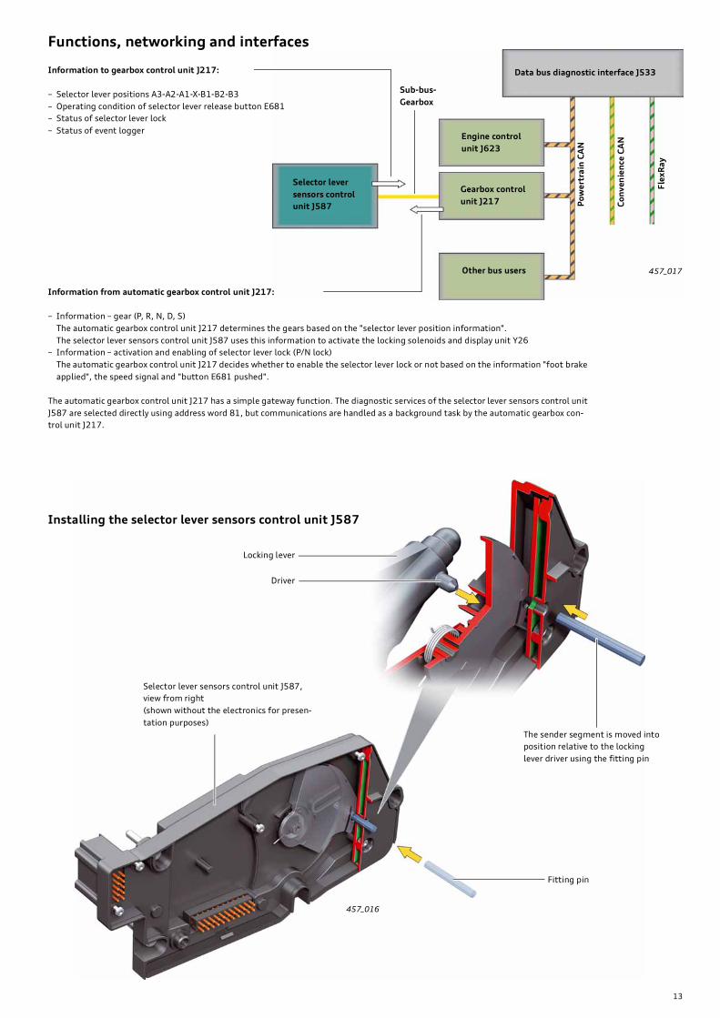
When installing the control unit, the gate of sender G727
must be positioned in relation to the arrow as shown.
The sender segment should always be pushed to the stop
by the force of the spring. For positioning, the sender
segment must be fixed in place from the other side using
a fitting pin (Ø 3 mm), see Fig. 457_016.
Gate
Sender segment
Selector lever position
sensor G727
Selector lever sensors control unit J587
Sender segment
Selector lever position sensor G727
The selector lever position sensor G727 records the movements or
positions of the selector lever (A3-A2-A1-X-B1-B2-B3).
Selector lever control unit J587 signals the selector lever position
to the gearbox control unit J217.
Gearbox control unit J217 uses this information to determine the
gear (P, R, N, D or S) and signals the active gear and information
for activating the P/N lock back to the selector lever control unit.
Locking solenoids N496 to N500 and the display unit Y26 are acti-
vated based on this feedback.
The speed signal and the brake signal which are required to gener-
ate the P/N lock signal are processed by the gearbox control unit.
10-pin connector to vehicle
electrical system
22-pin connector to gear
knob and locking solenoids
13
Functions, networking and interfaces
Information to gearbox control unit J217:
– Selector lever positions A3-A2-A1-X-B1-B2-B3
– Operating condition of selector lever release button E681
– Status of selector lever lock
– Status of event logger
457_017
457_016
Data bus diagnostic interface J533
Po
we
rtra
in C
AN
Fle
xR
ay
Co
nv
en
ien
ce C
AN
Other bus users
Engine control
unit J623
Sub-bus-
Gearbox
Gearbox control
unit J217
Selector lever
sensors control
unit J587
Information from automatic gearbox control unit J217:
– Information – gear (P, R, N, D, S)
The automatic gearbox control unit J217 determines the gears based on the "selector lever position information".
The selector lever sensors control unit J587 uses this information to activate the locking solenoids and display unit Y26
– Information – activation and enabling of selector lever lock (P/N lock)
The automatic gearbox control unit J217 decides whether to enable the selector lever lock or not based on the information "foot brake
applied", the speed signal and "button E681 pushed".
The automatic gearbox control unit J217 has a simple gateway function. The diagnostic services of the selector lever sensors control unit
J587 are selected directly using address word 81, but communications are handled as a background task by the automatic gearbox con-
trol unit J217.
Installing the selector lever sensors control unit J587
Locking lever
Driver
Selector lever sensors control unit J587,
view from right
(shown without the electronics for presen-
tation purposes)
The sender segment is moved into
position relative to the locking
lever driver using the fitting pin
Fitting pin
14
Both switches are monitored by the self-diagnostics. If a switch is
faulty, a fault will be indicated. However, the selector lever can
still be actuated as long as a switch is still working.
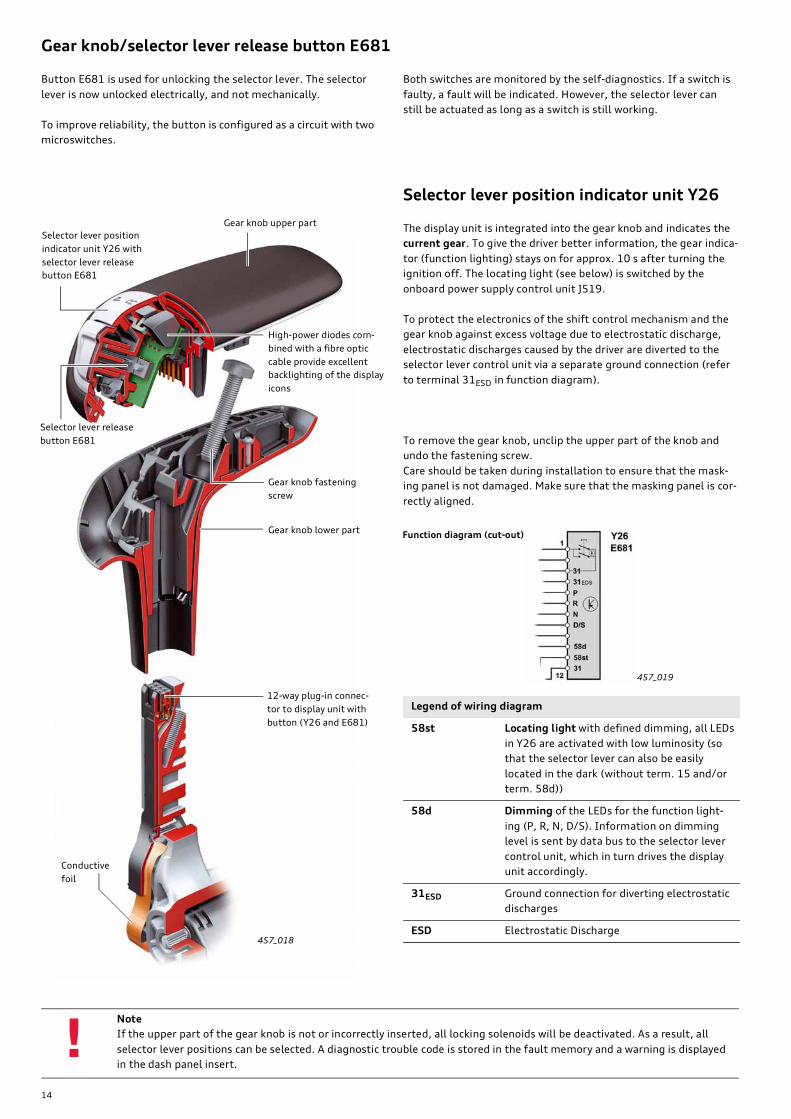
Selector lever position indicator unit Y26
The display unit is integrated into the gear knob and indicates the
current gear. To give the driver better information, the gear indica-
tor (function lighting) stays on for approx. 10 s after turning the
ignition off. The locating light (see below) is switched by the
onboard power supply control unit J519.
To protect the electronics of the shift control mechanism and the
gear knob against excess voltage due to electrostatic discharge,
electrostatic discharges caused by the driver are diverted to the
selector lever control unit via a separate ground connection (refer
to terminal 31ESD in function diagram).
To remove the gear knob, unclip the upper part of the knob and
undo the fastening screw.
Care should be taken during installation to ensure that the mask-
ing panel is not damaged. Make sure that the masking panel is cor-
rectly aligned.
Button E681 is used for unlocking the selector lever. The selector
lever is now unlocked electrically, and not mechanically.
To improve reliability, the button is configured as a circuit with two
microswitches.
457_018
457_019
Note
If the upper part of the gear knob is not or incorrectly inserted, all locking solenoids will be deactivated. As a result, all
selector lever positions can be selected. A diagnostic trouble code is stored in the fault memory and a warning is displayed
in the dash panel insert.!
Gear knob/selector lever release button E681
Selector lever position
indicator unit Y26 with
selector lever release
button E681
Gear knob upper part
Selector lever release
button E681
High-power diodes com-
bined with a fibre optic
cable provide excellent
backlighting of the display
icons
Gear knob fastening
screw
Gear knob lower partFunction diagram (cut-out)
12-way plug-in connec-
tor to display unit with
button (Y26 and E681)
Conductive
foil
Legend of wiring diagram
58st Locating light with defined dimming, all LEDs
in Y26 are activated with low luminosity (so
that the selector lever can also be easily
located in the dark (without term. 15 and/or
term. 58d))
58d Dimming of the LEDs for the function light-
ing (P, R, N, D/S). Information on dimming
level is sent by data bus to the selector lever
control unit, which in turn drives the display
unit accordingly.
31ESD Ground connection for diverting electrostatic
discharges
ESD Electrostatic Discharge
15
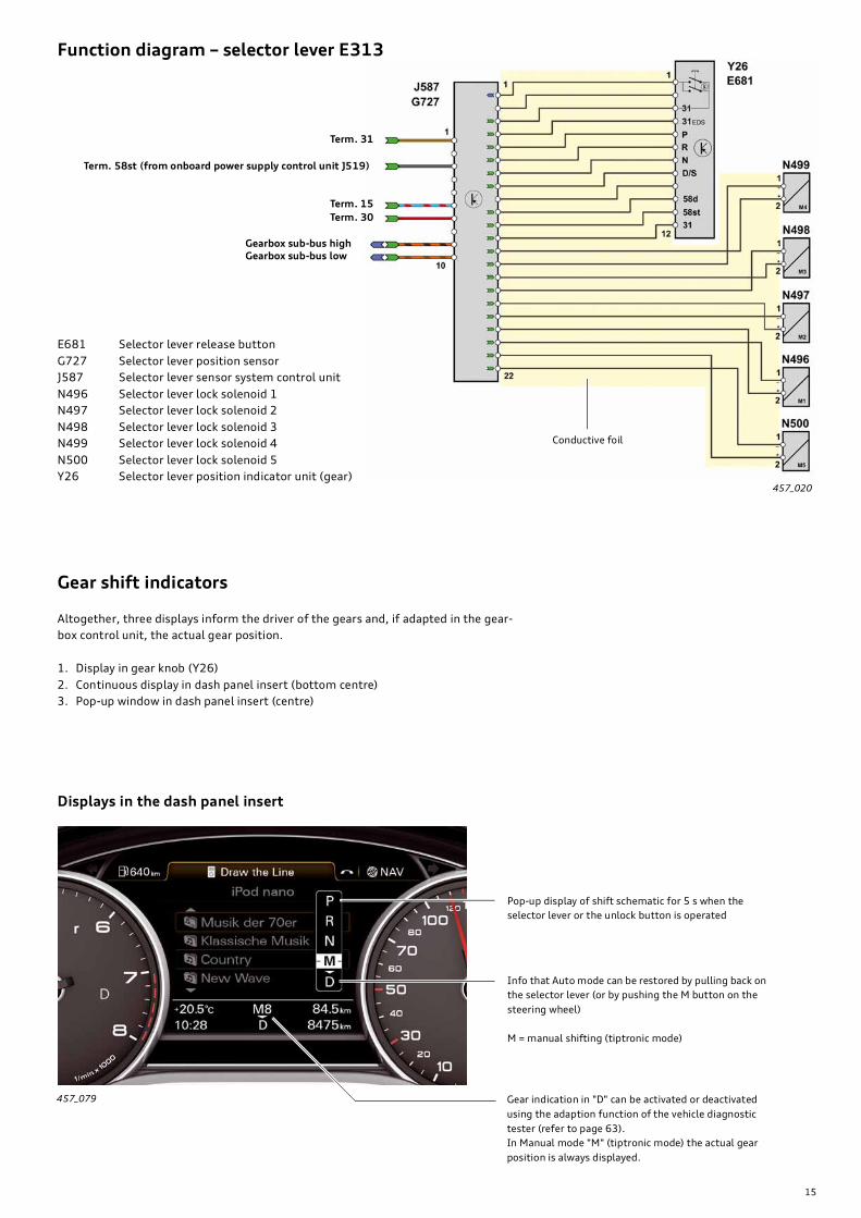
Function diagram – selector lever E313
457_020
457_079
Term. 31
Term. 58st (from onboard power supply control unit J519)
Term. 15
Term. 30
Gearbox sub-bus highGearbox sub-bus low
E681 Selector lever release button
G727 Selector lever position sensor
J587 Selector lever sensor system control unit
N496 Selector lever lock solenoid 1
N497 Selector lever lock solenoid 2
N498 Selector lever lock solenoid 3
N499 Selector lever lock solenoid 4
N500 Selector lever lock solenoid 5
Y26 Selector lever position indicator unit (gear)
Conductive foil
Gear shift indicators
Altogether, three displays inform the driver of the gears and, if adapted in the gear-
box control unit, the actual gear position.
1. Display in gear knob (Y26)
2. Continuous display in dash panel insert (bottom centre)
3. Pop-up window in dash panel insert (centre)
Displays in the dash panel insert
Pop-up display of shift schematic for 5 s when the
selector lever or the unlock button is operated
Info that Auto mode can be restored by pulling back on
the selector lever (or by pushing the M button on the
steering wheel)
M = manual shifting (tiptronic mode)
Gear indication in "D" can be activated or deactivated
using the adaption function of the vehicle diagnostic
tester (refer to page 63).
In Manual mode "M" (tiptronic mode) the actual gear
position is always displayed.

16
Possible ways of putting the gearbox into neutral:
1. Select position "N" with the shift control when the engine is run-
ning. Please note there are certain differences between vehicles
with and without advanced key system (refer to functional sche-
matics of "Auto P function").
– Active selection of position "N" is intended for briefly pushing
the vehicle because gear "N" is only available for a limited time.
This can, for example, be used for going through a car wash or
for pushing the vehicle inside a workshop or garage.
– When position "N" is actively selected, the gearbox control
unit and the selector lever control unit remain active (without
term. 15) and hold "N" for up to 30 minutes while the vehicle is
stationary1).
2. Engage position "N" using the emergency release device.
– If position "N" is to be engaged…
… for a lengthy period of time, …
… continuously, …
… when the engine is not running …
… or if the electro-hydraulic
parking lock mechanism fails, the emergency release device
must be operated.
This is the case, for example, if the vehicle needs to be towed or
parked in neutral.
Auto P function (automatic parking lock)
The parking lock in the new Audi A8 ’10 is actuated electro-hydrau-
lically. This design allows the parking lock to be operated automat-
ically for enhanced ease of use.
A description of how the parking lock works is given on page 48.
It is recommended that you read the description of how the park-
ing lock works in order to gain a better understanding of the Auto
P function.
The Auto P function engages the parking lock automatically, i.e.
without the driver's intervention, when the engine is turned off
(either using the ignition key or the START ENGINE STOP button).
The parking lock is engaged automatically when …
• the vehicle is stationary (speed < 1 kph),
• gear D, S, or R is active,
• and the engine is turned off (Term. 15 off (0)).
To put the gearbox into neutral, move the selector lever into "N"
when the engine is running or operate the emergency release
device for the parking lock.
457_022
457_021
shift-by-wire functions/operation
Functional schematic/Auto P function
Turn off engine in the current gear (D/S/
M or R)
v signal = 0 kph
Term. 15 = 0
Term. S = 1 or 0
Engine running,
select N,
turn off engine,
leave key in ignition
v signal = 0 kph
Term. 15 = 0
Term. S = 1
Functional schematic/active selection of gear "N"
in vehicles without advanced key Driver information in the
dash panel insert:
"Vehicle may roll.
Selector lever not in P"
+ continuous tone
If the ignition key is removed,
the parking lock will engage
Term. S = 0
Open driver door
1) The gearbox engages the parking lock automatically if the vehicle is stationary (v
= < 1 kph) for more than approx. 30 minutes.
If a speed signal is detected (v = > 1 kph), the time is extended accordingly until
either a standstill time of at least 5 minutes expires or the vehicle battery goes
flat.
The holding phase in "N" draws an electrical current of approx. 800 mA due in
order to power the gearbox control unit, the selector lever control unit and the
parking lock. A lengthy holding phase in position "N" will cause the battery to
discharge. To avoid this, the emergency release device for the parking lock
should be operated before a lengthy holding phase in "N" (refer to page 18).
The following driver information will be displayed
in the dash panel insert after 29 minutes:
"Time limit exceeded! Shifting to P. Start engine
for N" + continuous tone
If this warning is ignored, the parking lock will
engage after 30 minutes1).
T

17
Functional schematic/active selection of gear "N"
in vehicles with advanced key
The ignition lock will be deleted in vehicles with advanced key in Q3
2010. This will result in some changes with regard to the Auto P
function.
Important information
Information for vehicles without advanced key and vehicles with advanced key until Q3 20102).
When using automated conveyor-type car wash systems, the neutral position must be selected and the ignition key left
inserted in the ignition lock so that the gearbox stays in neutral.
To tow the vehicle or after leaving the gearbox in neutral for lengthy periods of time, the emergency release device for the
parking lock must be operated.
Do not forget to protect vehicle against unintentional rolling away (using the parking brake, wheel chocks etc.) if you have
selected position "N" or if the emergency release device for the parking lock has been operated.
!
457_023
2)Locking the vehicle
engages the parking
lock
1)Opening the driver's
door engages the park-
ing lock (at term. S = 0)
1)Removing the ignition
key engages the parking
lock (term. S = 0)
Engine running,
select position N,
turn off engine,
insert ignition key into ignition
lock1), see text on right
v signal = 0 kph
Term. 15 = 0
Term. S1)= 1
1) To keep the gearbox in neutral in vehicles
with advanced key, the key must be
inserted into the ignition lock (before
opening the driver's door).
Open driver's door
T
Description of maximum duration of
30 minutes1) see Fig. 457_022, page 16.
Driver information in the dash
panel insert: "Vehicle may roll.
Selector lever not in P"
+ continuous tone
The following driver information is dis-
played in the dash panel insert after 29
minutes:
"Time limit exceeded! Shifting to P. Start
engine for N" + continuous tone
If this warning is ignored, the parking
lock will engage after 30 minutes.
Legend
Term. 15 Voltage at "ignition on" (1)
Term. S Indicates whether ignition key is in ignition
lock (1) or not (0)
v signal Speed signal
(from automatic gearbox)
T Duration in neutral position
Driver action/other conditions
Action in gearbox
Display in dash panel insert
1)Vehicles with advanced key until Q3 20102)Vehicles with advanced key from Q3 2010
A new advanced key system will be introduced. The new
advanced key system does not have an ignition lock.

18
During normal operation the parking lock is actuated / unlocked
electro-hydraulically. As described on page 16, the engine must be
running to release the parking lock and a sufficient supply of
power is required to hold the gearbox in neutral (N holding phase).
In addition, the so-called N holding phase is limited in duration.
For these reasons, full implementation of the shift-by-wire system
(without selector lever cable) requires an emergency release device
for the parking lock. This is the only way to move the vehicle in cer-
tain situations.
457_025
457_026
Emergency release device for the parking lock
The emergency release device serves to temporarily release the
parking lock and must be actuated in the following situations:
• for towing the vehicle,
• if the parking lock cannot be released electro-hydraulically due
to a malfunction,
• to manoeuvre or move the vehicle if there is not enough battery
power to start the engine,
• to manoeuvre or move the vehicle when the engine is not run-
ning (e.g. in the workshop)
• after assembly work on components of the emergency release
device, the emergency release device must be checked (see
information on right-hand side).
Cover
Emergency release lever –
upper part (two-piece),
shown in blue
Band
Gearshift lever for
emergency release
of the parking lockReleasing the parking lock
1.Remove the cover using the tool kit. Pull out the emer-
gency release lever with the band until it engages and
locks in the upright position.
Cable pull 1
Quick-release coupling
To simplify installation, the emergency release
cable comprises two parts connected by a
quick-release coupling. When removing and
installing the gearbox, the emergency release
cable need only be disconnected or connected
here.
The cable pull does not have to be adjusted.
2.The emergency release lever is comprised of two
parts. The upper part has to be folded down so
that the lever cannot be unintentionally actuated
with the feet.
The cover is designed so that it cannot be installed
in this condition and should be set aside.
For detailed information on the parking lock, refer to page 16
(Auto P function) and page 48 (Parking lock).
Isolating element
The quick-release coupling and the mounting
of the emergency release device for the park-
ing lock are attached using special isolating
elements. This helps to minimise structure-
borne sound transmission.

19
When the emergency release device for the parking lock is oper-
ated, the warning lamp and gear indicator "N" light up in the dash
panel insert. The driver warning "Vehicle may roll!!
Cannot shift to P. Please apply parking brake."
Note
Do not forget to protect vehicle against unintentional rolling away (using the parking brake, wheel chocks etc.) if you have
selected gear "N" or if the emergency release device for the parking lock has been operated.
After removing and installing the gearbox or after assembly work on components of the emergency release device, a
functional check should be carried out as described in the Workshop Manual.
!
X
X
457_024 457_027
Warning lamp
Gearshift lever for emergency
release of the parking lock
Reduction of structure-borne sound transmission
A special feature is the connection between the emergency release
cable and the gearshift lever. A rigid rod and a conical nipple are
fitted on the end of the emergency release cable. The rod is guided
virtually backlash free and contactlessly by the gearshift lever. The
rod and the gearshift lever do not come into contact unless the
emergency release device is operated. This largely eliminates
transmission of structure-borne sound from the gearbox to the
cable pull (i.e. vehicle interior).
Contactless emergency release
cable connection
X = circumferential clearance (play)
(in non-actuated state only)
The illustration shows the emergency
release device in a left-hand-drive model. In
a right-hand-drive model, the emergency
release control is located on the right-hand
side.
Emergency release cable
Cable pull 2
Release lever
Releasing the parking lock
The release lever (shown in green) unlocks the emer-
gency release lever so that the parking lock can again
be engaged. This is done by pushing the release lever
against the emergency release lever and moving the
lever back into its normal position. The cover is
designed so that it can only be fitted if the emergency
release lever is folded down.
20
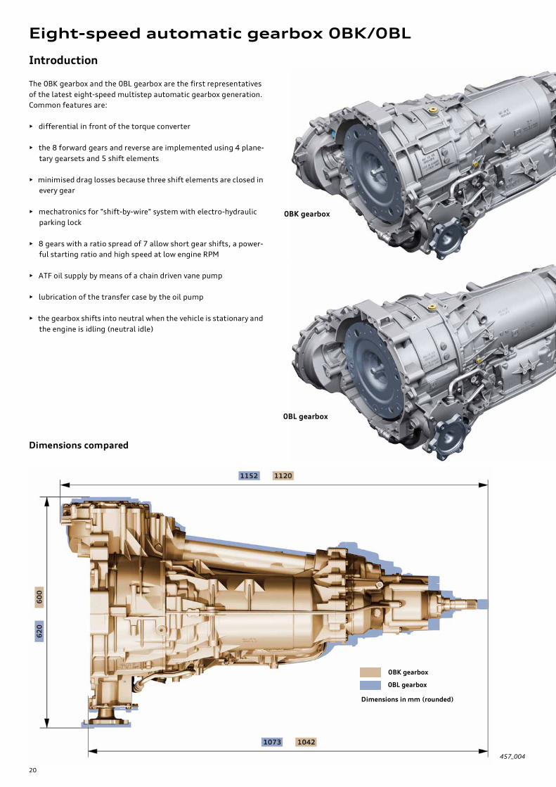
Introduction
The 0BK gearbox and the 0BL gearbox are the first representatives
of the latest eight-speed multistep automatic gearbox generation.
Common features are:
• differential in front of the torque converter
• the 8 forward gears and reverse are implemented using 4 plane-
tary gearsets and 5 shift elements
• minimised drag losses because three shift elements are closed in
every gear
• mechatronics for "shift-by-wire" system with electro-hydraulic
parking lock
• 8 gears with a ratio spread of 7 allow short gear shifts, a power-
ful starting ratio and high speed at low engine RPM
• ATF oil supply by means of a chain driven vane pump
• lubrication of the transfer case by the oil pump
• the gearbox shifts into neutral when the vehicle is stationary and
the engine is idling (neutral idle)
457_004
Dimensions compared
Eight-speed automatic gearbox 0BK/0BL
0BK gearbox
0BL gearbox
0BL gearbox
0BK gearbox
Dimensions in mm (rounded)

21
457_002
457_003
Specifications
0BK gearbox 0BL gearbox
Developer/manufac-
turer
ZF Getriebe GmbH Saarbrücken
Service designation 0BK 0BL
ZF designation 8HP-55AF 8HP-90AF
Audi designation AL551-8Q AL951-8Q
Gearbox type electro-hydraulically controlled 8-speed planetary gearbox with a hydrodynamic torque
converter and slip-controlled converter lockup clutch
Control • Mechatronics (integration of the hydraulic control unit and the electronic control sys-
tem unit)
• Dynamic shift program with separate sport program "S" and "tiptronic" shift program
for manual gear shifting
• shift-by-wire shift control system with electro-hydraulic parking lock function
Engine type • Longitudinally-mounted gearbox and all-wheel drive
• Final drive/front axle in front of torque converter
Power distribution Self-locking centre differential with asymmetrical/dynamic
torque split
Weight including oil 141 kg – 146 kg1)
Gear ratio 1st gear: 4.71; 2nd gear: 3.14; 3rd gear: 2.11; 4th gear: 1.67; 5th gear: 1.29; 6th gear:
1.00; 7th gear: 0.84; 8th gear: 0.67; Reverse: 3.32
Ratio spread 7.03 7.03
Max. torque 700 Nm1) 1000 Nm1)
1) depending on engine version
Seen from the exterior, there is hardly any difference between the
0BK and 0BL gearboxes. Because the 0BL gearbox is rated for a
maximum torque of 1000 Nm, most components of the
0BL gearbox are accordingly larger in size.
This also applies to the exterior dimensions of the gearbox, as
illustrated in Fig. 457_004 on page 20.

22
The illustrations show the 0BK gearbox
Special features and common features at a glance
Connector to vehicle electrical system Gearshift lever for emergency
release of the parking lock
Primary driveATF cooler (heat exchanger)
mounted on gearbox
The rating plate is located below the
flange shaft (visible from below)
Gearbox output shaft
with stub shaft spline
Splined prop shaft Spring sleeve
Transfer case oil pump
(refer to page 37)
Slot
Centre differential
Clamp
The joint is an integral part of the prop shaft and can-
not be replaced separately. The rubber sleeve can be
replaced using a special tool.

23
457_066
Torque converter
Transfer plate
Chain drive for laterally
positioned ATF pump
(twin stroke vane pump)
Engine and gearbox are connected
together by aluminium screws
(refer to SSP 385, page 31)
Oil drain port for double shaft
seal between planetary gearbox
and transfer case
The front axle differential has been notice-
ably set forward, thus reducing the dis-
tance between the gearbox flange and the
centre of the flange shaft to 43 mm from
61 mm.
The crown wheel is welded together with
the differential.
a biplanar angled
side shaft
ATF filler and level
checking screw
Sealed housing tube for the side shaft
(the differences between 0BK and 0BL
gearbox are discussed in "Oil system")
Splined prop shaft
For the first time, an innovative, new prop shaft coupling is used.
The prop shaft mated to the gearbox output shaft and locked into
a slot by means of a spring sleeve. The connection is secured axi-
ally by the clamping force exerted by the clamp. The new connec-
tion system provides a weight saving of 0.6 kg. The new
connection system will be phased in for all gearboxes in the course
of further development.
Centre differential
The self-locking centre differential with asymmetrical/dynamic
torque split used in the 0BK/0BL gearbox. It is similar in terms of
its design and function to the centre differential in the 0B2 and
0B5 gearboxes (refer to SSP 429, page 22 ff.).
The intelligent torque distribution (refer to page 66) is an innova-
tion.
Front axle spur pinion – the drive gear has a special tooth geometry which allows the
shaft to rotate at an angle in two planes (beveloid gearing)

24
The torque converters of the 0BK and 0BL gearboxes are config-
ured as so-called "three line converters". This means that the tur-
bine chamber is supplied by two lines and the lockup clutch is
activated by a separate line (third line). The lockup clutch closes
and opens independently of and separately from the turbine cham-
ber.
This design offers advantages in terms of controlling the lockup
clutch.
The pressure of the lockup clutch is controlled by the pressure reg-
ulating valve 6 N371 (refer to page 43) and the associated hydrau-
lic control valves.
Torque converter
The parameters (e.g. dimensions and torque conversion factor) of
the torque converter and the lockup clutch are adapted for each
engine. To effectively dampen the torsional vibration of the
engine, various torsion damper systems are used depending on
engine version. Use is made of turbine torsion dampers (on all
engines except the 3.0 V6 TDI) and dual-damper converters (3.0l
V6 TDI engine only).
For further information on the torque converters, refer to SSP 283
and 385.
457_029
Piston, brake BDrive hub for ATF pump with spline
and chain sprocket
The illustration shows a dual-damper converter.
Stator shaft
Torque converter centring
shaft – when installing the
gearbox make sure that the
torque converter centring
shaft mates exactly with the
crankshaft.
Spline for drive hub – ATF
pump
ATF pump – twin-stroke
vane pump
Gear chainSun gear shaft S1/S2
Brake A
Effective damping systems and precision lockup clutch control
allow a further minimisation of torque converter slip from first
gear upwards. Furthermore, a direct and dynamic driving feel is
achieved without any adverse acoustic effects.
The neutral idle control also minimises converter loss torque when
the engine is idling and the vehicle is stationary (also refer to page
52).
These modifications give a significant improvement in fuel econ-
omy compared to the previous six-speed gearboxes.

25
ATF supply/ATF pump
One of the key components of an automatic gearbox is the ATF
pump.
No gearbox can function without a sufficient supply of oil.
Special features are the lateral, axle-parallel configuration and the
chain drive. The different ratios of the chain drive allow the deliv-
ery rate of the pump to be adapted to meet various requirements.
The ATF pump is a highly efficient twin-stroke vane pump. It also
makes a contribution to improving fuel economy.
The ATF pump takes in the ATF through a filter and conveys pressu-
rised oil to the system pressure valve in the hydraulic unit. Here
the system pressure is adjusted to the level required for operation
of the gearbox. Excess oil is returned to the ATF pump through the
intake duct, which provides ideal conditions of flow. The energy
liberated in this way is utilised to charge the intake side. In addi-
tion to increased efficiency, noise emission is reduced by avoiding
cavitation.
457_030
System pressure
valve
System pressure – to
hydraulic valves
System pressure – to
converter pressure
valve
Control pressure from pres-
sure regulating valve 7 N443
ATF suction filterATF pan
Recirculation of excess
oil
to ATF pump
Sleeve with duct for direct, flow-
optimised recirculation to the ATF
pump
System pressure valve
from ATF suction filter
ATF (Automatic Transmission Fluid)
The ATF is a "hightech product". The special requirements with
respect to shift quality, functional reliability and freedom from
maintenance (lifetime service) mean that the ATF needs to satisfy
very exacting standards. The ATF has a major impact on the fric-
tion in the clutches and brakes. This is why the ATF is codeveloped
during the design and testing phases.
Always make sure that the correct ATF is used and pay attention
to cleanliness and grade purity.
The ATF pump is installed in the gearbox as an assembly, the so-
called "oil supply". The assembly includes the following compo-
nents:
• Pump housing
• ATF pump drive hub
• ATF pump chain drive
• ATF pump
• Housing of brake A
• Brake A
• Piston and piston chambers of brake B
• Stator shaft (fixed)
A new feature is that power is transmitted from the torque con-
verter housing to the ATF pump drive hub through a spline. Again,
care must be taken to ensure that the converter and the drive hub
are correctly mated when installing the converter.
Important: when installing the converter, pay attention to fit-
ting dimensions.

26
Planetary gearbox
The 8 forward gears and the reverse gear are produced by a combi-
nation of four simple single-carrier planetary gearsets. The front
two gearsets share a common sun gear. Power is output always
through the planetary carrier of the fourth gearset.
E
C
D
RS1
RS2
RS3
PT1
PT3
Shift elements
Only 5 shift elements are used to shift 8
gears.
2 multidisc brakes – A and B
3 multi-plate clutches – C, D and E
The shift elements, clutches or brakes close
hydraulically. Oil pressure compresses the
clutch plate assembly and engages the
clutch.
When the oil pressure drops, the diaphragm
spring abutting the piston pushes the piston
back into its original position.
The shift elements allow gearshifts to be exe-
cuted under load and without any interrup-
tion in tractive power flow.
Multi-plate clutches C, D and E transfer
engine power to the planetary gearbox. Multi-
disc brakes A and B multiply the torque at the
gearcase.
When each individual gear is engaged, three
shift elements are closed and two shift ele-
ments are open (see shift matrix on page 28).
This constellation has a very positive effect on
gearbox efficiency since each open shift ele-
ment produces a certain amount of drag
torque during operation.
Brake A Brake B
Resetting spring
(diaphragm
spring), brake A
Clutch E
Pressure compensation
chamber
Baffle plate
Pressure chamber
Piston
ATF pump
Resetting spring (diaphragm spring)

27
457_032
RS4
B1
Clutch D
Piston, brake B
Clutch C
B2
Brakes
Brake B has a special design. The piston of brake B does not have a
resetting spring. This task is performed by a second piston cham-
ber (piston chamber B2).
Brake B has a piston chamber (cylinder) on both sides (piston
chamber B1 and piston chamber B2).
Piston chamber B1 is for closing the brake and piston chamber B2
functions as a resetting spring (opening the brake). When brake B
is vented, a certain amount of oil pressure is retained inside piston
chamber B2 in order to push the piston back into its rest position.
Brake B is operated with slip in neutral idle mode (refer to page
52). Brake B is specially rated for continuous duty in neutral idle
mode. It is also cooled in a controlled fashion when activated by
the hydraulic unit.
Brake A is fitted with a resetting spring.
Legend of planetary gearbox
RS1 (2, 3, 4) Planetary gearset 1 (2, 3, 4)
PT1 (2, 3, 4) Planet carrier 1 (2, 3, 4)
S1 (2, 3, 4) Sun gear of planetary gearset 1 (2, 3, 4)
P1 (2, 3, 4) Planetary gears of planetary gearset 1 (2, 3, 4)
H1 (2, 3, 4) Ring gear of planetary gearset 1 (2, 3, 4)
Clutches
Clutches E, C and D are dynamically pressure-equalised. This
means that the clutch piston is swept by oil on both sides in order
to avoid any speed-related increase in pressure in the clutch.
This pressure-equalising effect is achieved by using a second pis-
ton chamber - the pressure equalisation chamber. In the case of
clutch D, the pressure equalisation chamber is created by means of
a baffle plate. In the case of clutches C and E, the clutch plate
carrier acts as a barrier. Oil is pressurelessly supplied to the
pressure equalisation chamber through lubrication ducts.
Advantages of dynamic pressure equalisation are:
• reliable opening and closing of the clutch at all engine speeds
• greater ease of shifting
Planet carrier PT4 also acts as the gearbox
output shaft, the parking lock gear and the
encoder wheel for the gearbox output speed
sender G195
To illustrate the shift elements and the planetary gearsets more clearly,
several parts are not shown (e.g. the outer plate carriers of the shift
elements).
Reference
The function of the shift elements and the dynamic pressure equalisation system is described in detail in SSP 283 and
SSP 367.
28
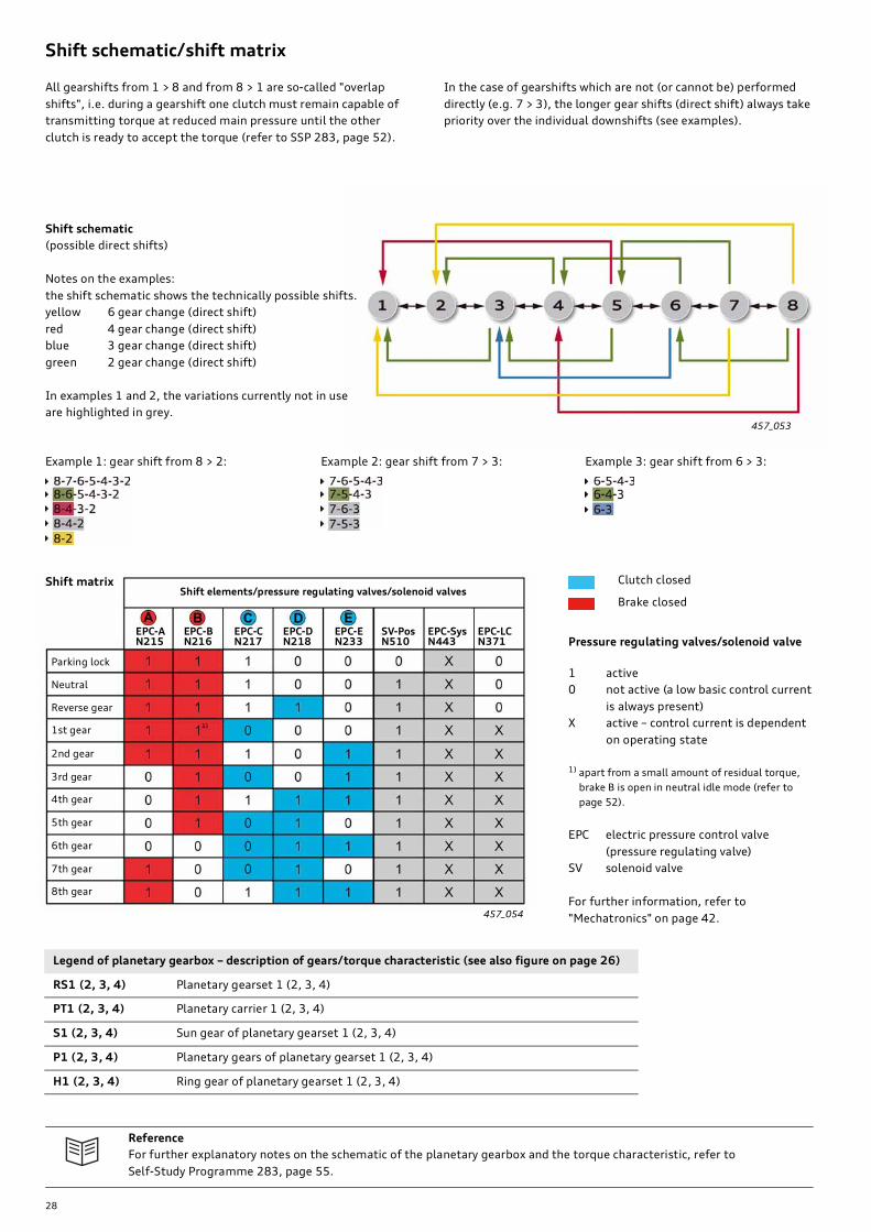
In the case of gearshifts which are not (or cannot be) performed
directly (e.g. 7 > 3), the longer gear shifts (direct shift) always take
priority over the individual downshifts (see examples).
Shift schematic/shift matrix
All gearshifts from 1 > 8 and from 8 > 1 are so-called "overlap
shifts", i.e. during a gearshift one clutch must remain capable of
transmitting torque at reduced main pressure until the other
clutch is ready to accept the torque (refer to SSP 283, page 52).
457_053
457_054
Shift schematic
(possible direct shifts)
Notes on the examples:
the shift schematic shows the technically possible shifts.
yellow 6 gear change (direct shift)
red 4 gear change (direct shift)
blue 3 gear change (direct shift)
green 2 gear change (direct shift)
In examples 1 and 2, the variations currently not in use
are highlighted in grey.
Example 1: gear shift from 8 > 2: Example 2: gear shift from 7 > 3: Example 3: gear shift from 6 > 3:
Brake closed
Clutch closedShift matrixShift elements/pressure regulating valves/solenoid valves
EPC-AN215
EPC-BN216
EPC-CN217
EPC-DN218
EPC-EN233
SV-PosN510
EPC-SysN443
EPC-LCN371
Parking lock
Neutral
Reverse gear
1st gear
2nd gear
3rd gear
4th gear
5th gear
6th gear
7th gear
8th gear
Pressure regulating valves/solenoid valve
1 active
0 not active (a low basic control current
is always present)
X active – control current is dependent
on operating state
1) apart from a small amount of residual torque,
brake B is open in neutral idle mode (refer to
page 52).
EPC electric pressure control valve
(pressure regulating valve)
SV solenoid valve
For further information, refer to
"Mechatronics" on page 42.
Legend of planetary gearbox – description of gears/torque characteristic (see also figure on page 26)
RS1 (2, 3, 4) Planetary gearset 1 (2, 3, 4)
PT1 (2, 3, 4) Planetary carrier 1 (2, 3, 4)
S1 (2, 3, 4) Sun gear of planetary gearset 1 (2, 3, 4)
P1 (2, 3, 4) Planetary gears of planetary gearset 1 (2, 3, 4)
H1 (2, 3, 4) Ring gear of planetary gearset 1 (2, 3, 4)
Reference
For further explanatory notes on the schematic of the planetary gearbox and the torque characteristic, refer to
Self-Study Programme 283, page 55.

29
457_044
457_045
457_046
Torque characteristic/power flow
Stationary parts (blocked by foot brake)
Co-rotating parts not contributing to
power flow
Planetary gearset in blocking mode or
blocked
Description of gears – torque characteristic
Power flow in 1st gear – activated shift elements: A, B, C
Turbine shaft > clutch C > S4 > P4 > PT4 (> output shaft > transfer case …)
2nd gear
i = 3.14
Power flow in 2nd gear – activated shift elements: A, B, E
Turbine shaft > PT2 > P2 > H2 > clutch E > S4 > P4 > PT4 (> output shaft > transfer case …)
3rd gear
i = 2.11
Power flow in 3rd gear – activated shift elements: B, E, C
1. Turbine shaft > clutch C > S4 > P4 > PT4 (> output shaft > transfer case …)
2. Clutch C > clutch E > H2 > P2 (RS2 blocks power transmission, because H2 and PT2 are connected through clutches C
and E)
3. Turbine shaft > PT2 > S2 (PT2 in blocking mode) > S1 > P1 > PT1 > H4
The connection between PT1 and H4 produces a corresponding ratio in RS4 (compare to power flow in first gear)
1st gear
i = 4.71

30
457_047
457_048
457_049
Power flow in 4th gear – activated shift elements: B, E, D
1. Clutch E blocks power transmission in RS3, and clutch D and the blocking mode of RS3 block power trans-
mission in RS4 (gearsets 3 and 4 rotate at the same speed = output speed)
2. Turbine shaft > PT2 > P2 > S2/S1 > P1 > PT1 > H4 > P4 > PT4 (= output shaft > transfer case …)
4th gear
i = 1.67
Power flow in 5th gear – activated shift elements: B, C, D
1. Turbine shaft > clutch C > S4 + H3 (PT2, H2 and S4 = turbine speed)
2. Clutch D connects PT3 to PT4 (= output shaft)
3. Turbine shaft > PT2 > P2 > S2/S1 > P1 > PT1 > H4 > results in a speed ratio between S4 (=turbine speed) and H4 with corre-
sponding speed at PT4 (= output shaft > transfer case …)
5th gear
i = 1.29
Power flow in 6th gear – activated shift elements: C, D, E
Clutches E and D block power transmission in RS3 and RS4.
Torque is transmitted to the planetary gearbox through clutch C.
The complete planetary gearbox rotates at turbine speed (blocking mode).
6th gear
i = 1.00

31
457_050
457_051
457_052
Torque characteristic/power flow
Stationary parts (blocked by brake(s))
Co-rotating parts not contributing to
power flow
Planetary gearset in blocking mode or
blocked
Power flow in 7th gear – activated shift elements: A, C, D
1. Turbine shaft > clutch C > S4 + H3 (= turbine speed)
2. Turbine shaft > PT2 > P2 > H2 > S3 > P3 > PT3 > clutch D > PT4 (= output shaft > transfer case …}
Clutch D connects PT3 to PT4 (= output shaft)
7th gear
i =0.84
Power flow in 8th gear – activated shift elements: A, E, D
1. Clutch E blocks power transmission in RS3
2. Turbine shaft > PT2 > P2 > H2 > RS3 (blocking mode) > clutch D > PT4 (= output shaft > transfer case …)
Clutch D connects PT3 to PT4 (= output shaft)
8thgear
i = 0.67
Power flow in reverse gear – activated shift elements: A, B, D
1. Clutch D connects PT3 to PT4 (= output shaft)
2. Turbine shaft > PT2 > P2 > H2 > S3 > P3 > PT3 > clutch D > PT4 (= output shaft > transfer case …)
H3 is permanently connected to S4. S4 drives P4 in the opposite direction of rotation to that of the engine.
Gears P4 roll against fixed gear H4 and rotate PT4 in the opposite direction of rotation to that of the engine and at the specified ratio.
Reverse gear
i = 3.32
32
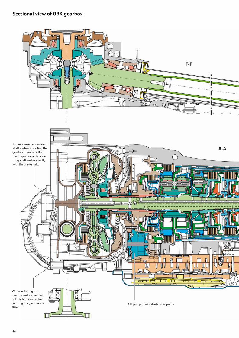
Sectional view of 0BK gearbox
Torque converter centring
shaft – when installing the
gearbox make sure that
the torque converter cen-
tring shaft mates exactly
with the crankshaft.
When installing the
gearbox make sure that
both fitting sleeves for
centring the gearbox are
fitted.ATF pump – twin-stroke vane pump
33
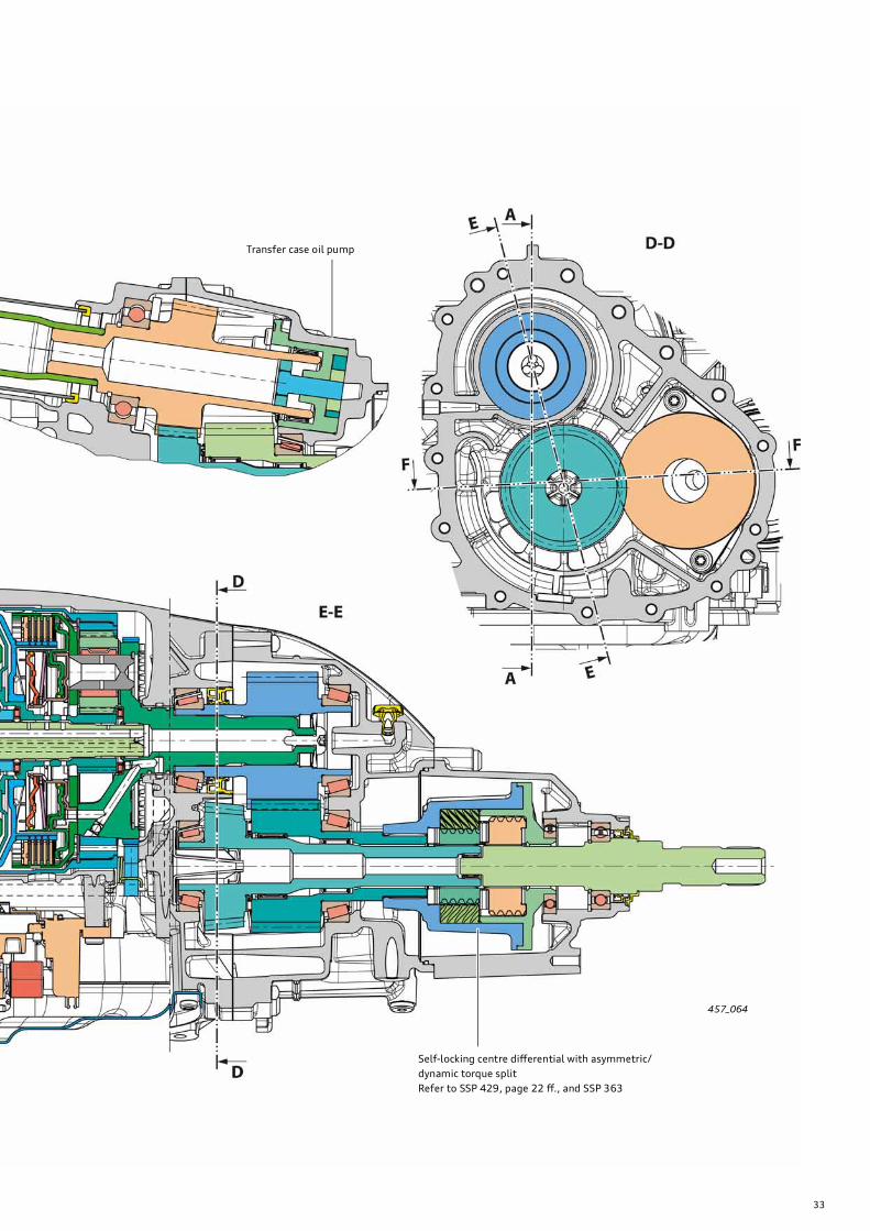
457_064
Transfer case oil pump
Self-locking centre differential with asymmetric/
dynamic torque split
Refer to SSP 429, page 22 ff., and SSP 363

34
Oil system/lubrication/sealing of 0BK gearbox
There are two versions of the oil system in the 0BK gearbox:
1. Separate oil systems
The oil chambers (oil systems) of the transfer case and front axle
differential are separate. The gearbox has a total of three separate
oil systems (oil chambers) filled with different types of oil:
ATF oil system for the planetary gearbox, the hydrau-
lic control unit and the torque converter
Oil system for the transfer case (gear oil with
STURACO1))
Oil system for the front axle drive (gear oil without
STURACO1))
This double shaft seal and the seal-
ing disc separate the ATF oil system
from the transfer case oil system.
The oil drain port is located on the
left-hand side of the gearbox level
with the shaft seal (see Fig.
457_066 on page 22).
Sealing disc
Transfer case breather
Gear oil filler and level check-
ing screw for transfer case
Gear oil drain screw
(for transfer case)
Aluminium ATF pan
(refer to SSP 385, page 32 ff.)
ATF filler and level checking screw
Side shaft housing tube
Transfer case oil pump
Side shaft housing tube
Oil is supplied to the ATF oil system by a highly efficient vane pump
(see "ATF pump" on page 25).
The transfer case oil pump provides controlled and reliable lubrica-
tion of all bearings and gears in the transfer case. This design
allows highly efficient lubrication with a minimal oil level. Churn-
ing losses are significantly reduced and foaming of the oil is mini-
mised.
This design was adopted for the first time for the 09E gearbox and
differs only slightly in the 0BK gearbox. The functional principle is
described in greater detail in SSP 283, page 70 ff.
This double shaft seal separates
the oil system of the front axle dif-
ferential from the transfer case oil
system.
Oil drain port directly below
(not shown here, see Fig.
457_073 on page 45)
35
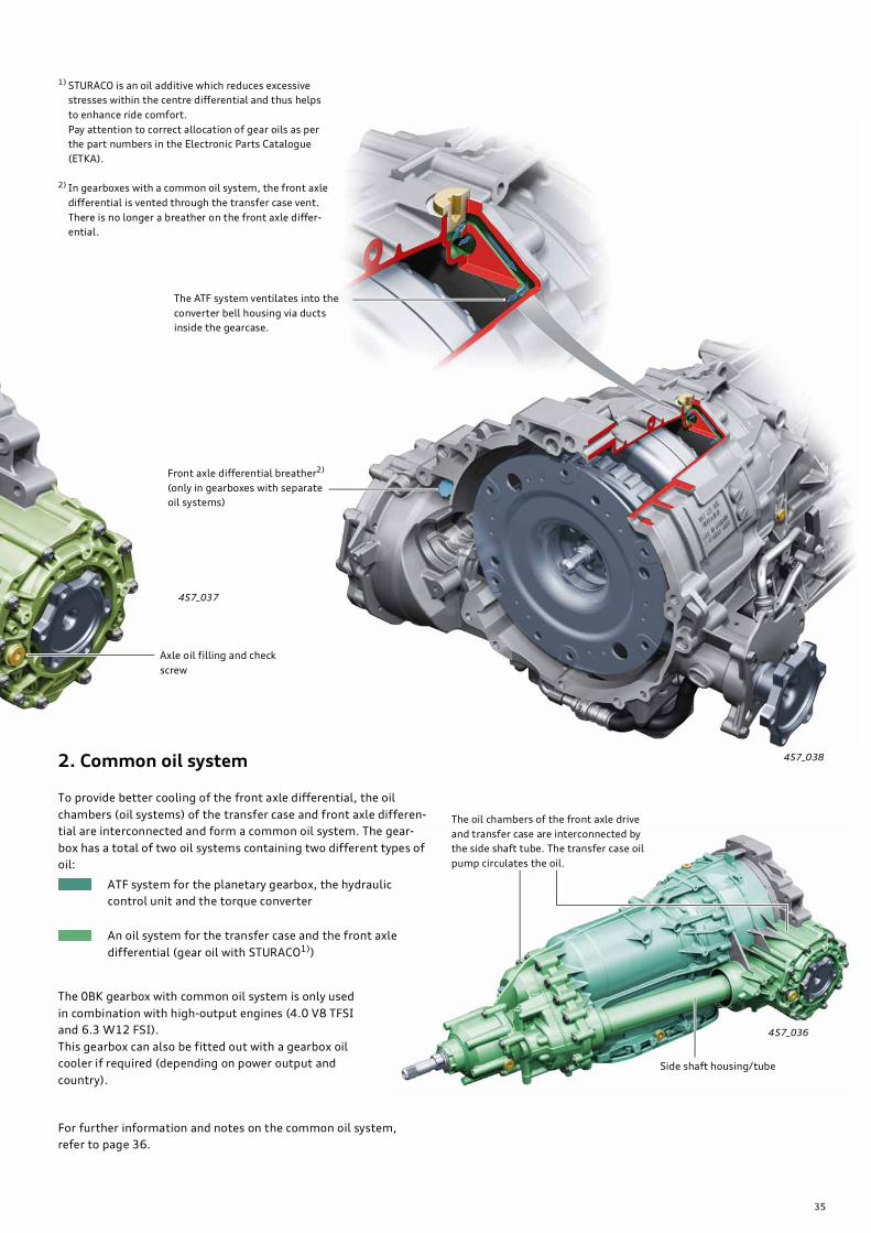
457_037
457_038
457_036
Front axle differential breather2)
(only in gearboxes with separate
oil systems)
The ATF system ventilates into the
converter bell housing via ducts
inside the gearcase.
1) STURACO is an oil additive which reduces excessive
stresses within the centre differential and thus helps
to enhance ride comfort.
Pay attention to correct allocation of gear oils as per
the part numbers in the Electronic Parts Catalogue
(ETKA).
2) In gearboxes with a common oil system, the front axle
differential is vented through the transfer case vent.
There is no longer a breather on the front axle differ-
ential.
Axle oil filling and check
screw
2. Common oil system
To provide better cooling of the front axle differential, the oil
chambers (oil systems) of the transfer case and front axle differen-
tial are interconnected and form a common oil system. The gear-
box has a total of two oil systems containing two different types of
oil:
ATF system for the planetary gearbox, the hydraulic
control unit and the torque converter
An oil system for the transfer case and the front axle
differential (gear oil with STURACO1))
The 0BK gearbox with common oil system is only used
in combination with high-output engines (4.0 V8 TFSI
and 6.3 W12 FSI).
This gearbox can also be fitted out with a gearbox oil
cooler if required (depending on power output and
country).
For further information and notes on the common oil system,
refer to page 36.
Side shaft housing/tube
The oil chambers of the front axle drive
and transfer case are interconnected by
the side shaft tube. The transfer case oil
pump circulates the oil.

36
Gear oil system (common oil system)
To provide better cooling of the front axle differential, the oil
chambers (oil systems) of the transfer case and the front axle
differential are interconnected and form a common oil system.
The oil pump in the transfer case provides efficient and reliable
lubrication of the transfer case and conveys cooler gear oil to the
front axle drive.
This design was adopted for the first time for the 09E gearbox and
differs only slightly in the 0BL gearbox. The functional principle is
described in greater detail in SSP 283, page 70 ff.
Basically, the 0BL gearbox has only two oil systems - an oil system
filled with ATF and an oil system filled with gear oil (axle oil).
457_055
Oil system/lubrication/sealing of 0BL gearbox
ATF system for the planetary gearbox, the hydraulic
control unit and the torque converter
Gear oil system for the transfer case and the front axle
differential (gear oil with STURACO1))
Oil is supplied to the ATF oil system by a highly efficient vane
pump (see "ATF pump" on page 25).
This double shaft seal and the
sealing disc separate the ATF oil
system from the transfer case oil
system.
The oil drain port is located on the
left-hand side of the gearbox level
with the shaft seal (see Fig.
457_066 on page 23).
ATF system ventilation,
see Fig. 457_038 on page 35.
The front axle differential is ventilated
through the transfer case breather via the
side shaft housing tube.
Sealing disc
Transfer case breather
ATF filler and level check-
ing screw
Side shaft
housing tube
Axle oil filling and
check screw
Gear oil drain screw
(for transfer case)
Aluminium ATF pan
(refer to SSP 385, page 32 ff.)
Transfer case oil pump
Gear oil filler and level checking
screw for transfer case
Oil return line from front axle differential to transfer case
via the housing tube (without shaft oil seal)
Note
Because of the common oil system, there is a special procedure for filling and checking the gear oil in the front axle differ-
ential and transfer case. Different levels are possible depending on the driving situation.
When checking the oil level, therefore, the oil level must always be adjusted at both check-points.
Refer to the Workshop Manual.
!
37
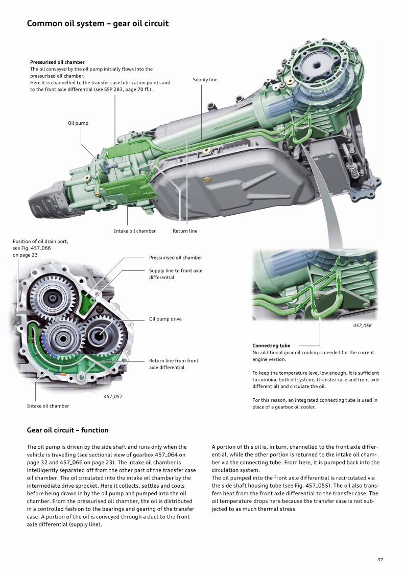
457_056
457_057
Common oil system – gear oil circuit
Pressurised oil chamber
The oil conveyed by the oil pump initially flows into the
pressurised oil chamber.
Here it is channelled to the transfer case lubrication points and
to the front axle differential (see SSP 283, page 70 ff.).
Supply line
Oil pump
Return lineIntake oil chamber
Position of oil drain port,
see Fig. 457_066
on page 23
Return line from front
axle differential
Oil pump drive
Supply line to front axle
differential
Pressurised oil chamber
Intake oil chamber
Connecting tube
No additional gear oil cooling is needed for the current
engine version.
To keep the temperature level low enough, it is sufficient
to combine both oil systems (transfer case and front axle
differential) and circulate the oil.
For this reason, an integrated connecting tube is used in
place of a gearbox oil cooler.
Gear oil circuit – function
The oil pump is driven by the side shaft and runs only when the
vehicle is travelling (see sectional view of gearbox 457_064 on
page 32 and 457_066 on page 23). The intake oil chamber is
intelligently separated off from the other part of the transfer case
oil chamber. The oil circulated into the intake oil chamber by the
intermediate drive sprocket. Here it collects, settles and cools
before being drawn in by the oil pump and pumped into the oil
chamber. From the pressurised oil chamber, the oil is distributed
in a controlled fashion to the bearings and gearing of the transfer
case. A portion of the oil is conveyed through a duct to the front
axle differential (supply line).
A portion of this oil is, in turn, channelled to the front axle differ-
ential, while the other portion is returned to the intake oil cham-
ber via the connecting tube. From here, it is pumped back into the
circulation system.
The oil pumped into the front axle differential is recirculated via
the side shaft housing tube (see Fig. 457_055). The oil also trans-
fers heat from the front axle differential to the transfer case. The
oil temperature drops here because the transfer case is not sub-
jected to as much thermal stress.

38
The air conditioner and gearbox control unit indicate their heating
requirements to the engine control unit via CAN bus. This informa-
tion, together with the engine heating requirements, is then
weighted, prioritised and used to generate activation signals for
the ITM components (valves and controls).
By way of example, the function and design of the gearbox heat-
ing and cooling system are discussed here in combination with the
4.2l V8 FSI engine. Other engine combinations differ from one
another. Refer to "ATF cooling - 0BL gearbox"
(4.2l V8 TDI engine) on page 40.
For further information on the ITM system, refer to SSP 456.
The gearbox cooling system is a part of the Innovative Thermal
Management system – or ITM for short.
The aim of the Innovative Thermal Management system is to
improve fuel economy by shortening the warm-up phase of the
engine and gearbox.
The "Heat Manager" – a newly developed software module in the
engine control unit – provides optimal distribution of the heat gen-
erated by the engine within the engine cooling circuits (engine
heating) to the air conditioning system (interior heating) and to
the gearbox (gearbox heating).
6
54
3
2
1
457_040
G694
N509
V51
V50
N82
G62
N488
7
Innovative Thermal Management (ITM)
Function diagram – coolant system of Audi A8 ’10 with 4.2l V8
FSI engine and 0BK gearbox
Gearbox heating/gearbox cooling – V8 FSI engine
Heater heat exchanger Heater heat exchanger, rear
ATF heat exchanger
Radiator
G62 Coolant temperature sender
G694 Engine temperature control temperature sender
N82 Coolant shutoff valve (activated by Climatronic J255)
N488 Gearbox coolant valve (activated by engine control unit J623)
N509 Gearbox cooling valve (activated by gearbox control unit J217)
V50 Coolant circulation pump (activated by Climatronic J255)
V511) Coolant run-on pump (activated by engine control unit J623)
1 Crankcase breather heater
2 Heat exchanger for engine oil cooling
3 Alternator
4 Coolant pump
5 Coolant thermostat (F265 map-controlled engine cooling thermostat)
6 Coolant expansion tank
7 Coolant shutoff valve (vacuum controlled) is activated by cylinder head
coolant valve N489, which, in turn, is activated by engine control unit J623
1) V51 runs in ATF cooling and after-cooling modes

39
Gearbox heating function
(Fig. 357_041)
Initial situation – engine/gearbox cold
The gearbox control unit signals its heating requirements to the
engine control unit 1) (the objective is to heat up the ATF as quickly
as possible). The engine first tries to heat up as quickly as possi-
ble. Solenoid valves N509 (energised) and N488 (deenergised) are
closed.
N488 is not opened (energised) until the engine has reached a pre-
determined target temperature. Warm coolant now flows from
the cylinder heads to the ATF heat exchanger. The ATF is heated.
1) The heating requirements of the air conditioning system
(interior heating) have the highest priority. In this case,
engine and gearbox heating are secondary.
457_042
457_041
N488
X
X
N509
V51
From the engine
(from the cylinder heads)
Return line to coolant
thermostat
(to engine)
ATF heat exchanger
View X
View XGearbox cooling function
(Fig. 357_042)
Initial situation – engine/gearbox at operating temperature
The gearbox heating phase ends when a defined ATF temperature
is exceeded and N488 is closed (turned off). If the ATF tempera-
ture continues to increase, N509 is opened (deenergised) and
cooled coolant flows from the radiator to the ATF heat exchanger.
If the ATF temperature rises to 96 °C, pump V51 is activated to
increase cooling capacity.

40
457_039
V50
N488
9
4
G62
7
1
3
1
G83
V400
2
N509
5
V51
7
8
6
G694
Function diagram – coolant system of Audi A8 ’10
with 4.2l V8 TDI engine and 0BL gearbox
Gearbox heating/gearbox cooling – V8 TDI engine
Heater heat exchanger, rearHeater heat exchanger
ATF heat exchanger
Radiator
G62 Coolant temperature sender
G83 Radiator outlet coolant temperature sender
G694 Engine temperature control temperature sender
N488 Gearbox coolant valve (activated by engine control unit J623)
N509 Gearbox cooling valve (activated by gearbox control unit J217)
V50 Coolant circulation pump (activated by Climatronic J255)
V511) Coolant run-on pump (activated by engine control unit J623)
V400 EGR cooler pump
1 Exhaust turbocharger
2 Heat exchanger for engine oil cooling
3 Alternator
4 Switchable coolant pump – vacuum controlled (by N492 coolant circuit
solenoid valve, activated by engine control unit J623)
5 Coolant thermostat (with F265 map-controlled engine cooling thermo-
stat)
6 Coolant expansion tank
7 Exhaust gas recirculation valve, cylinder bank 1/2
8 Exhaust gas recirculation cooler
9 Exhaust gas recirculation coolant thermostat
1) V51 runs in ATF cooling and after-cooling modes 2) applies to page 41 – The heating requirements of the air conditioning system
(interior heating) have the highest priority. In this case, engine and gearbox
heating are secondary.

41
457_058
N509
X
X
V51
N488
457_059
457_060
N509
V51
N488
457_061
Return line to coolant ther-
mostat (to engine)
from engine
(from coolant pump)
View X
Gearbox heating function
Initial situation – engine/gearbox cold
The gearbox control unit signals its heating requirements to the engine control unit 2)
(the objective is to heat up the ATF as quickly as possible).
The engine first tries to heat up as quickly as possible. Solenoid valves N509 (energised) and
N488 (not energised) are closed and coolant pump 4 (Fig. 457_039) is off (not shown).
Coolant pump 4 (Fig. 457_039) is not activated and N488 is not opened (energised) until the
engine has reached a predetermined target temperature. Warm coolant now flows from the
coolant thermostat and the coolant pump to the ATF heat exchanger via N488. The ATF is
heated.
Return line to coolant
thermostat (to engine)
ATF heat exchangerView X
Gearbox cooling function
Initial situation – engine/gearbox at operating temperature
The gearbox heating phase ends when a defined ATF temperature is exceeded. First of all,
N488 is closed (turned off). If the ATF temperature continues to increase, N509 is opened
(turned off) and cooled coolant flows from the radiator to the ATF heat exchanger.
If the ATF temperature rises to approx. 96 °C, pump V51 is activated to increase cooling
capacity.

42
The increased number of gears has drastically increased the com-
plexity of the clutch control mechanism. This means that an 8-2
downshift can be achieved in various ways. The shift schematic
shows the variety of possible shift sequences.
A major innovation contributing to improved gear selection is the
inclusion of route data from the navigation system.
This supplementary information, which provides the driver with a
view of the road ahead, makes possible an anticipatory shift strat-
egy with matching gear selection.
Refer to "Navigation-based gear selection", page 58 ff.
The neutral idle control, which minimises torque converter loss
when the vehicle is stationary (e.g. when waiting at traffic lights),
was previously introduced in the 0B6 gearbox (refer to SSP 385).
Thanks to systematic further development of the hardware and
software, the neutral idle control system in the 0BK and 0BL gear-
boxes sets new standards in terms of comfort and fuel economy
(refer to page 52).
To enable the mechatronics to perform these tasks in a highly
dynamic fashion, the electrical control unit has been fundamen-
tally reworked. The hydraulic control unit and the gearbox mecha-
nism have to be able to react to electrical commands very quickly.
In this case too, shift dynamics and control quality have been fur-
ther improved by enhancing component design.
457_053
457_062
Mechatronics – electro-hydraulic control system
The shift program selects a suitable shift sequence based on the
driver's reaction, driving situation and driving program. The aim is
to execute as direct a shift as possible (refer to page 28).
Mechatronics (E26/6)
ATF pump pressure
connection
Hydraulic control unit
Automatic gearbox control unit J217 (elec-
trical control unit)
Gearbox input speed sender
G182
Connector for vehicle
Intake port to
ATF pumpE module
Parking lock slide valve
Parking lock solenoid N486
Parking lock sender G747
ATF temperature sender G93
Connector/wiring harness for parking lock
solenoid N486 and pressure accumulator
solenoid N4851)
Hydraulic Impulse Storage1)
1)only available in combination with start-stop system
(refer to page 54)

43
N215
N218
N216
N233
N217
N371
N443
N88
457_063
Special care must be taken to ensure that the electronics
are protected against electrostatic discharge. Please follow
the guidelines and instructions given in SSP 284 (page 6)
and in the Workshop Manual.
Mechatronics (E26/6)
Wiring harness from vehicle
to E module
Connection for ATF suction
filter (for ATF pump)
Wiring harness from E module
to parking lock solenoid N486
(refer to page 48)
N88 Solenoid valve 1 (SV-Pos)
N215 Pressure regulating valve 1 (EPC-A)
N216 Pressure regulating valve 2 (EPC-B)
N217 Pressure regulating valve 3 (EPC-C)
N218 Pressure regulating valve 4 (EPC-D)
N233 Pressure regulating valve 5 (EPC-E)
N371 Pressure regulating valve 6 (EPC-LC)
N443 Pressure regulating valve 7 (EPC-Sys)
N486 Parking lock solenoid
Gearbox output speed sender
G195
To achieve high shift dynamics and a variety of shift sequences, a
separate electrical pressure regulating valve (EPC) is assigned to
each shift element.
Mechatronics/automatic gearbox control unit J217
The mechatronics are integrated into the immobiliser system,
which means that there is no hydro-mechanical limp-home func-
tion (see SSP 385, page 52 ff.).
Due to the special demands on and complexity of the self-diagnos-
tics, the 0BK and 0BL gearboxes have adopted the diagnostic data
description (to ASAM/ODX standard) which Audi used for the first
time in the 0B6 gearbox (refer to SSP 385, page 35).
Replacing the mechatronics
Care must be taken to ensure that the control unit and electronic
components are not damaged by electrostatic discharges when
replacing the mechatronics.
After a gearbox software update or after replacing the mechatron-
ics, the following points must be checked and carried out:
• Control unit coding (refer to page 63)
• Adaption of the gear indicator (refer to page 63)
• Adaption of the shift elements (refer to page 53)
Reference
For general information and notes on the mechatronics and the sensors, refer to Self-Study Programme 284 and 385.

44
Two types of electronic pressure regulating valve are fitted:
• EDC with rising characteristic – deenergised – no control pres-
sure (0 mA = 0 bar)
• EDC with falling characteristic – deenergised – maximum control
pressure (0 mA = approx. 5 bar)
Mechatronics – actuators
Pressure regulating valves, also referred to as EPCs (electric pres-
sure control valves), convert a control current to a hydraulic con-
trol pressure. They are activated by the gearbox control unit and
control the hydraulic valves (slide valves) belonging to the shift
elements.
457_070
457_068
457_067
457_069
Pressure regulating valves 1, 2, 4, 5, 6 (orange)
Pressure regulating valves – solenoid valves
1 N215 pressure regulating valve 1 – brake A
2 N216 pressure regulating valve 2 – brake B
4 N218 pressure regulating valve 4 – clutch D
5 N233 pressure regulating valve 5 – clutch E
6 N371 pressure regulating valve 6 – lockup
clutch
Pressure range 0 to 4.7 bar
Operating voltage 12 V
Resistance at 20 °C 5.05 ohms
Characteristic rising
3 N217 pressure regulating valve 3 – clutch C
7 N443 pressure regulating valve 7 – system
pressure
Pressure range 4.7 to 0 bar
Operating voltage 12 V
Resistance at 20 °C 5.05 ohms
Characteristic falling
Pressure regulating valves 3, 7 (white)
N88 is an electrically operated solenoid valve.
It is a so-called 3/2 valve, i.e. it has 3 terminals and
2 switching positions (open/close or on/off).
Solenoid valve 1 – N88 (black/brown)
Operating voltage < 16 V
Pick-up voltage > 6 V
Dropout voltage < 5 V
Resistance at 20 °C 11 ohms +/- 2 ohms
N88 is activated by the gearbox control unit and controls both the
position valve and the parking lock valve. The position valve
replaces the previous gear selector valve for selector lever cable
operated shift controls. The position valve regulates the system
pressure for the various clutches and brake control operations.
The parking lock valve controls the system pressure for the park-
ing lock slide valve. The parking lock slide valve operates the park-
ing lock - a task it has taken over from the selector lever cable.
The task of the parking lock slide valve is to disengage the parking
lock (refer to "Parking lock", page 48 ff.).
Parking lock
Neutral
Reverse gear
1st gear
2nd gear
3rd gear
4th gear
5th gear
6th gear
7th gear
8th gear
EPC-AN215
EPC-BN216
EPC-CN217
EPC-DN218
EPC-EN233
SV-PosN510
EPC-SysN443
Shift matrixShift elements/pressure regulating valves/solenoid valves
Pressure regulating valves/solenoid valve
1 active
0 not active (a low basic control current
is always present)
X active – control current is depending
on operating condition
1) apart from a small amount of residual torque,
brake B is open in neutral idle mode (refer to
page 52).
Brake closed
Clutch closed
EPC Electric pressure control valve
(pressure regulating valve)
SV Solenoid valve

45
Parking lock solenoid – N486 (green)
457_072
457_073
457_071
The parking lock solenoid N486 serves to hold of the
parking lock slide valve in the "parking lock disen-
gaged" position (refer to "Parking lock", page 48 ff.).
Operating voltage < 16 V
Pick-up voltage > 8 V
Resistance at 20 °C 25 ohms +/- 2 ohms
Hydraulic interfaces
Brake B1
Lockup clutch closed
from torque converter
to torque converter
Brake B2
Intake to ATF pump
Oil supply from ATF pump
Clutch D
Clutch C
Clutch E
Brake A
Cooling, brake B
Parking lock solenoid
N486
from cooler
to cooler
Connector for wiring harness to
parking lock solenoid N486
parking lock slide valve
Clutch E
Clutch C
Brake B1
Close lockup clutch
from torque converterBrake B2
to torque converter
Intake to ATF pump
Oil supply from ATF pump
from cooler
to cooler Parking lock
Cooling, brake B
Clutch D
Oil drain port for double shaft seal
(available only in the 0BK gearbox with separate oil system)
Brake A
46
To measure the temperature of the microprocessor (main proces-
sor of J217) as accurately as possible, a so-called substrate tem-
perature sensor is integrated into the substrate1) of the
semiconductor blocks.
1) "substrate" is the base ceramic of the semiconductor components or
microprocessor. The substrate temperature sensor is integrated directly in
the substrate adjacent to the microprocessor and measures the substrate
temperature directly in situ.
Due to the integration of the electronics into the (ATF-lubricated)
gearbox, it is very important to monitor the control unit tempera-
ture, i.e. the ATF temperature.
High temperatures have a significant impact on the service life and
performance of electronic components.
Temperatures over 120 °C shorten the service life of electronic
components in the control unit. At temperatures over 150 °C, it is
no longer possible to rule out damage to components, and hence
malfunctioning of the whole system.
To provide protection against overheating, countermeasures are
taken when predetermined threshold temperatures are exceeded.
The DSP (dynamic shift program) has separate programs specifi-
cally for this purpose (refer to SSP 284, page 41 Hotmode pro-
grams).
Monitoring of temperature in J217
Hotmode
Hotmode is subdivided into 3 stages:
Stage 1 > 124 °C substrate temperature
(126 °C ATF temperature, G93)
The shift points are adjusted to higher RPM using the DSP func-
tion. The operating range within which the lockup clutch is closed
is extended.
Stage 2 > 139 °C substrate temperature
(141 °C ATF temperature, G93)
Engine torque is significantly reduced depending on the extent to
which the temperature continues to increase.
Stage 3 > 145 °C substrate temperature
(147 °C ATF temperature, G93)
For protection against overheating of the control unit (associated
with malfunctioning and component damage), the power supply to
the solenoid valves is disconnected. The gearbox loses positive
engagement. A fault is stored in the event logger.
All temperature specifications refer to the software version valid
at the time of preparation of the SSP. The temperature specifica-
tions for other software versions can differ.
Monitoring of the oil temperature spectrum
The control unit J217 checks the current gearbox temperature
range at regular intervals using the gearbox oil (ATF) temperature
sender G93. The measurement data is stored. From this data it is
possible to determine the thermal load on the gearbox through-
out its life cycle. This is referred to as an oil temperature
spectrum2).
The oil temperature spectrum is used by the manufacturer for ana-
lysing component damage to the E module of the mechatronics.
2) A spectrum is a collection of measured data or readings of any size which
can be used for statistical evaluation by means of weighting and quantifi-
cation.

47
For further information on the functional principle of Hall sensors,
refer to SSP 268, page 34 ff.
Sensors G93, G182, G195 and G747 are integral to the E module.
The E module cannot be replaced separately. In the event of a fault
in one of the specified components, the complete mechatronics
must be replaced.
Mechatronics – sensors
Speed senders G182, G195 and the parking lock sender G747 are
configured as Hall sensors.
For information on the parking lock sender G747, refer to page 51.
For further information on the speed senders and the ATF temper-
ature sender G93, refer to SSP 283, page 16 ff.
457_075
Contrary to the information given in SSP 268, the gearbox input
speed sender G182 has an encoder wheel with a magnetic ring.
The encoder wheel is connected to planetary carrier 2.
G182 measures the rotational speed of the planetary carrier of the
second planetary gearset (PT2). Planetary carrier 2 is interlock-
ingly connected to the turbine shaft.
(turbine input speed = gearbox input speed).
The cylinder connecting the planetary carrier 1 to the ring gear 4 is
located above the magnetic ring encoder wheel. The cylinder is
made of a high-strength aluminium alloy. The material is there-
fore non-magnetic and the magnetic fields produced by the mag-
netic ring act upon the sensor G182 through the cylinder. Metal
swarf on the encoder wheel can affect the performance of the
encoder wheel to a greater or lesser extent.
The gearbox input speed sender G182 and the gearbox output
speed sender G195 are so-called intelligent sensors. They recog-
nise the direction of rotation and changes in the magnetic field
strength, and adapt the tolerances of the gap between the sensor
and the encoder wheel.
Gearbox input speed sender G182Gearbox output speed sender G195
Gearbox input speed sender G182 Gearbox output speed sender G195

48
N486
457_076
Parking lock
The parking lock in the new Audi A8 ’10 is electro-hydraulically
operated. The parking lock is controlled by the mechatronics.
It can be controlled either manually by the driver (using the shift
control) or automatically by the Auto P function (refer to page 16).
The parking lock mechanism in the gearbox derives from the previ-
ous mechanism.
The parking lock is engaged by spring force. It is electro-hydrauli-
cally operated and protected electromagnetically.
The following components engage, disengage and hold the
parking lock:
1. Engaging the parking lock:
• Parking lock spring
• Parking lock lever
• Linkage
• Conical slide valve with
spring
• Pawl
2. Disengaging the
parking lock:
• Solenoid valve N88
• Parking lock valve
• Parking lock slide valve
3. Holding the disengaged
parking lock:
• Parking lock solenoid N486
Pawl with spring
Parking lock gear
Linkage
N88
Parking lock lever with
spring
Conical slide
valve with
spring
Catch spring Parking lock engaged
(engine at standstill)
Depressurised (0 bar)
Control pressure (approx. 5 bar)
System pressure
(approx. 5 bar - 16.5 bar)
Parking lock valveParking lock slide valve
Piston
Catch hook
Locking element
Parking lock – function
Engaging the parking lock
If solenoid valve N88 and solenoid N486 are deenergised, the
parking lock is engaged (e.g. when the engine is turned off or when
gear P is selected - refer to "Auto P function" on page 16). The
parking lock valve moves into its normal position and the cylinder
chamber of the parking lock slide valve is depressurised and
evacuated.
When solenoid N486 is deenergised, the piston of N486 pushes
the catch springs apart. The catch hooks release the locking
element and hence also the parking lock slide valve.
The spring of the parking lock lever pushes the pawl into the
parking lock gear. The parking lock is engaged.
Disengaging the parking lock
Basically, the parking lock is disengaged by electro-hydraulic
activation of the parking lock slide valve. The hydraulic force is
several times greater than the spring force of the spring on the
parking lock lever. The necessary hydraulic pressure is produced by
the ATF pump.
Note: to disengage the parking lock, the engine must be run-
ning.
If the engine is not running, the parking lock can be disengaged
using the parking lock emergency release (refer to "Parking lock
emergency release", page 18 ff.).

49
457_077
N88
N486
N88
Disengaging the parking lock or parking lock disengaged
(engine running)
To disengage the parking lock, solenoid valve N88 and solenoid
N486 are energised. The control pressure of solenoid valve N88
acts on the parking lock valve. The slide valve moves into its work-
ing position and releases the system pressure to the parking lock
slide valve cylinder. The parking lock slide valve pulls the conical
slide valve out of the pawl, thus disengaging the parking lock.
As an additional safeguard against a possible drop in pressure, the
parking lock slide valve is locked in position using N486
(see next page).
Pawl with spring
Parking lock gear
Linkage
Control pressure
N88
If the solenoid N486 is ener-
gised, the piston is retracted.
The catch springs now return
to their normal position and
the catch hooks engage the
shoulder of the locking ele-
ment.
Disengage parking lock or parking lock
disengaged (engine at standstill)
System pressure Parking lock valve
Parking lock slide valve is
locked electromagnetically
Hold parking lock disengaged
(neutral holding position, engine at
standstill)
To keep the parking lock disengaged
after the engine has been turned off,
the selector lever must be moved into
N before turning off the engine
(refer to "shift-by-wire – functions/
operation", page 16 ff.).
The pressure in the system is reduced as described under "Engaging the parking lock" .
The solenoid N486 stays energised. The parking lock slide valve is now held in position by the
catch springs. This neutral holding position is maintained for a limited time only because it uses
up battery power (refer to "shift-by-wire – functions/operation", page 16 ff.
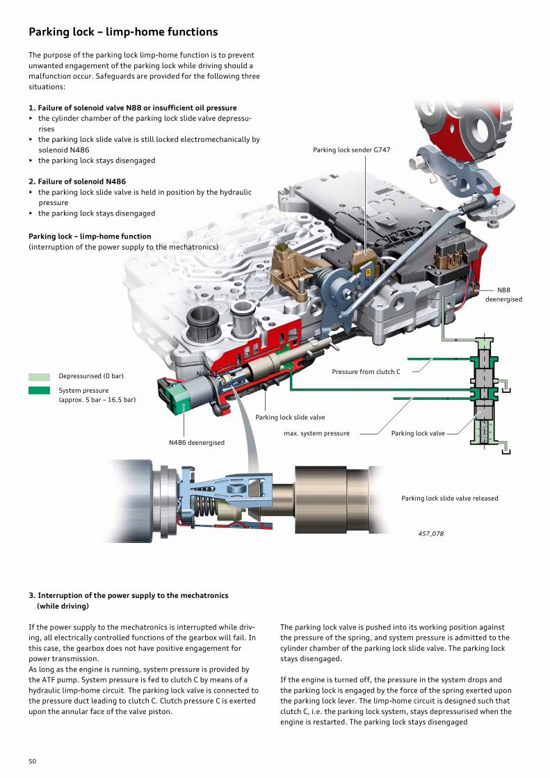
50
457_078
N486
Parking lock – limp-home functions
The purpose of the parking lock limp-home function is to prevent
unwanted engagement of the parking lock while driving should a
malfunction occur. Safeguards are provided for the following three
situations:
1. Failure of solenoid valve N88 or insufficient oil pressure
• the cylinder chamber of the parking lock slide valve depressu-
rises
• the parking lock slide valve is still locked electromechanically by
solenoid N486
• the parking lock stays disengaged
2. Failure of solenoid N486
• the parking lock slide valve is held in position by the hydraulic
pressure
• the parking lock stays disengaged
Parking lock – limp-home function
(interruption of the power supply to the mechatronics)
Parking lock sender G747
N88
deenergised
Pressure from clutch CDepressurised (0 bar)
System pressure
(approx. 5 bar – 16.5 bar)
max. system pressure Parking lock valve
N486 deenergised
Parking lock slide valve
Parking lock slide valve released
3. Interruption of the power supply to the mechatronics
(while driving)
If the power supply to the mechatronics is interrupted while driv-
ing, all electrically controlled functions of the gearbox will fail. In
this case, the gearbox does not have positive engagement for
power transmission.
As long as the engine is running, system pressure is provided by
the ATF pump. System pressure is fed to clutch C by means of a
hydraulic limp-home circuit. The parking lock valve is connected to
the pressure duct leading to clutch C. Clutch pressure C is exerted
upon the annular face of the valve piston.
The parking lock valve is pushed into its working position against
the pressure of the spring, and system pressure is admitted to the
cylinder chamber of the parking lock slide valve. The parking lock
stays disengaged.
If the engine is turned off, the pressure in the system drops and
the parking lock is engaged by the force of the spring exerted upon
the parking lock lever. The limp-home circuit is designed such that
clutch C, i.e. the parking lock system, stays depressurised when the
engine is restarted. The parking lock stays disengaged

51
The P sensor determines/recognises the following positions:
P engaged —> intermediate position —> P not engaged.
The intermediate position does not normally exist during opera-
tion and is defined as a fault after a predetermined filtering time.
The parking lock sender G747 has the following tasks:
1. Monitoring the proper functioning of the parking lock
2. Start enabling in P (the sensor signal is directly converted to a
P/N signal by the gearbox control unit)
3. Display in dash panel insert "Gearbox in position P"
4. Display in dash panel insert when parking lock emergency
release is actuated
Parking lock sender G747
The position of the parking lock is monitored by the gearbox con-
trol unit using a sensor - the parking lock sender G747.
G747 is comprised of two Hall sensors. The Hall sensors are oper-
ated by a permanent magnet on the parking lock lever.
457_094
Gearbox input speed sender G182
Parking lock sender G747
Permanent magnet
Linkage with conical slide valve for
actuating the parking lock
Parking lock lever
If G747 fails or is faulty (e.g. intermediate position), this has
following effects:
• Fault message in dash panel insert
• The system pressure is set to maximum (to ensure that the
parking lock slide valve has maximum power)
• The engagement of the parking lock is not indicated in the dash
panel insert (even if it is engaged).Information regarding point 3, page 50:
First of all, clutch C or clutch E has to be activated so that the
limp-home circuit (described under point 3) is functional. This is
the case with one of the eight forward gears (refer to "Shift
matrix" on page 28).
If the power supply is interrupted while the selector is in position R
or N, the parking lock is engaged unless either of the two clutches
has previously been activated as described above.

52
The neutral idle control was introduced in an early version of the
0B6 gearbox (refer to SSP 385). Thanks to systematic further
development of the hardware and software, the second genera-
tion of the neutral idle control (in the 0BK and 0BL gearboxes) sets
new standards in terms of comfort and fuel economy.
In addition to reducing the converter residual torque, response to
positive engagement has been improved.
The neutral idle control can be activated and deactivated by means
of encoding (refer to page 63).
The neutral idle control system is also referred to as NIC.
Functions – neutral idle
The neutral idle control significantly improves fuel economy in city
traffic. This is achieved by interrupting the transmission of con-
verter loss torque when the engine is idling, when driving for-
wards, when the vehicle is stationary and when the foot brake is
applied.Engine idling torque is reduced to a minimum, e.g. when
waiting at traffic lights. In addition to the advantages in terms of
fuel efficiency at engine idle, both acoustics and ride comfort are
improved. As there is less load on the engine, it runs more
smoothly and quietly. Reducing torque to a small residual amount
keeps brake pedal force to a minimum.
The neutral idle control is implemented in the 0BK and 0BL gear-
boxes by opening brake B. Opening brake B interrupts the trans-
mission of multiplying torque to ring gear 1. The torque is diverted
to brake B .
Brake B is operated with slip in neutral idle mode. Brake B is spe-
cially rated for continuous duty in neutral idle mode. It is also
cooled in a controlled fashion when activated by the hydraulic unit.
457_081
Neutral idle control not activated
Torque converter housing/pump gear turn at
engine idling speed
Brakes A and B and clutch C are fully
engaged
Status: engine idling, forward gear (1st gear), vehicle stationary
Turbine shaft/
gearbox input shaft and
all other shafts are sta-
tionary
100 % slip in
converter
Gearbox output shaft stationary
Neutral idle control activated
Torque converter housing/pump gear
turning at engine idling speed
Brakes B in slip mode, clutch C and brake A are
fully engaged
approx. 10 % slip
in converter
Turbine shaft/
gearbox input shaft
turning at close to
engine idling speedStatus: engine idling speed, forward gear (1st gear), vehicle stationary
Note: all parts coloured black are stationary.
Gearbox output shaft stationary
Reference
The neutral idle control function is described in SSP 385, page 36 ff. Apart from minor changes in the values given, this
description also applies to the 0BK and 0BL gearboxes.
53
Functions – gearbox adaption
A detailed description of the gearbox adaption process can be
found in SSP 385, page 54 ff. and also applies to the 0BK and 0BL
gearboxes. The 0BK and 0BL gearboxes have the new data and
diagnostic log previously used in the 0B6 gearbox (refer to
SSP 385, page 35 and SSP 392, page 90). For this reason,
pages 61 and 64 concerning the reading and deleting of adaption
values are relevant to the 0BK and 0BL gearboxes.
To ensure good shift quality, it is necessary that the 5 shift ele-
ments (brakes A and B and clutches C,D and E) be correctly
adapted.
For example, the adaption values are deleted after a software
update is performed. In this case, an adaption cycle must be
carried out using the vehicle diagnostic tester. The exact proce-
dure is explained in the Guided Functions and Guided Fault Finding
and is self-explanatory.
Nothwithstanding the content of SSP 385, the adaption proce-
dures and adaption conditions are listed below in summary form
for the 0BK and 0BL gearboxes.
The following adaption procedures are used:
• Shift adaption (during an upshift or downshift)
Shift adaption is mainly used for quick adaption (start adaption).
• Slip adaption
• Pulse adaption (continuous adaption of the shift elements)
Quick adaption – slip adaption
(from an ATF temperature of 40 °C)2)
In neutral idle mode, brake B is additionally adapted by means of
slip adaption.
This adaption takes approx. 7 seconds.
The quick adaption and pulse adaption run concurrently.
This means that the corresponding adaption is carried out depend-
ing on which conditions are met first. As mentioned, this is the
quick adaption (limited to 4).
Quick adaption – shift adaption
(from an ATF temperature of 40 °C)2)
Brake A 6 —> 7 shift1)
Brake B 6 —> 5 rolling gearshift
Clutch C 2 —> 3 shift1)
Clutch D 3 —> 4 shift1)
Clutch E 1 —> 2 and 5 —> 6 shift1)
Pulse adaption
(ATF temperature 50 °C – 110 °C)2)
Brake A 6th gear selector cable, load: 80 – 180 Nm,
turbine speed 1200 – 2100 rpm
(charging pressure/quick charge time)
Brake B 7th gear selector cable, load: 80 – 180 Nm, turbine
speed 1200 – 2100 1/min (quick charge time only,
the charging pressure of brake B is adapted for roll-
ing gearshift 6 —> 5)
Clutch C 4th gear selector cable, load: 30 – 100 Nm, turbine
speed 1200 – 1700 rpm (charging pressure/quick
charge time)
Clutch D 3rd gear selector cable, load: 30 – 100 Nm, turbine
speed 1200 – 1700 rpm (charging pressure/quick
charge time)
Clutch E 7th gear selector cable, load: 80 – 180 Nm, turbine
speed 1200 – 2100 rpm (charging pressure/quick
charge time)
Result of adaption
The evaluation of shift quality is mandatory. The number of adap-
tions can be checked by referring to the corresponding measured
value (e.g. analysis 3 for the charging pressure adaption of brake
A). Each count should have a value of at least 3. The individual shift
elements can be adapted separately, if need be.
As a rule, no vehicle should be handed over to the customer if one
or more shift elements are not adapted.
1) With regard to upshifts, the shift elements can be adapted up to
four times by means of shift adaption at loads of up to 150 Nm.
2) The "general boundary conditions" must be observed. For fur-
ther information, refer to the description of the adaption proce-
dure in SSP 385.

54
The problem with start-stop operation:
When the engine is turned off, the oil supply in the gearbox shuts
down. The shift elements of each gear open and power transmis-
sion is interrupted. When the engine is started, the gearbox must
be positively engaged and thus ready for start up. In the case of
the eight-speed automatic gearbox, means that three shift ele-
ments have to be closed (refer to shift matrix).
The volume of oil delivered by the ATF pump at engine start-up is
not enough to pressurise the shift elements within the required
time and provide sufficient positive engagement.
In principle, the ATF pump could be configured so as to meet this
requirement. However, such a pump would incur totally unaccepta-
ble losses at low engine speeds.
For the first time in the V6 3.0 TDI, the start-stop function is used
in combination with an automatic gearbox.
The start-stop function represents a major challenge for the auto-
matic gearbox. In start-stop mode, the system has to be ready to
start up within an extremely short period of time. To ensure there
is no noticeable delay, the engine and automatic gearbox must be
ready for start-up after approx. 350 ms.
An automatic gearbox cannot meet this requirement unless it is
specially configured and the oil supply is modified accordingly.
457_083
457_082
Functions – start-stop system
Hydraulic Impulse Storage – HIS
Hydraulic connection Pressure accumulator solenoid
N485
16 ohms +/- 2 (at 20 °C)
Wiring harness to
mechatronics
The Hydraulic Impulse Storage system has an effective capacity of
approx. 100 cm3.
The solution – Hydraulic Impulse Storage (HIS)
A highly efficient solution to this problem is the so-called
"Hydraulic Impulse Storage" system (HIS).
The HIS is a special oil reservoir with an electromechanical locking
unit.
It provides torque-transmissible pressure to the shift elements
with a fraction of a second. The HIS ingeniously ensures the
start-up readiness of the gearbox within about 350 ms.
Start-up readiness with HIS
Start-up readiness without HIS
Engine start speed
System pressure with HIS
Pressure HIS
System pressure without HIS
barrpm
ms
Comparison of start-up readiness with and without Hydraulic Impulse Storage – HIS

55
457_084
457_085
Installation location/connections
The HIS is installed below oil level. The piston spring reservoir therefore can-
not run empty and always stays full when charged.
Oilway to mechatronics
Connection to mechatronics for the wiring
harnesses of the N485 and the N486
Design and function
The HIS comprises the piston spring oil reservoir system, an elec-
tromechanical locking unit (pressure accumulator solenoid N485)
and a one-way restrictor. The piston spring oil reservoir consists of
a piston, cylinder and steel spring. The task of solenoid N485 is to
keep the piston preloaded (N485 energised).
The piston spring oil reservoir is "charged" when the engine is run-
ning. When the engine is started, solenoid N485 is deenergised
and the oil stored in the reservoir is forced into the hydraulic con-
trol (discharged) by the force of the spring.
This means that the shift elements are subjected to oil pressure as
soon as the ATF pump begins to operate. The HIS thus assists the
ATF pump and enables the pressure to build up extremely quickly.
The pressures built up by the HIS system and by the ATF pump
overlap when the pump begins to deliver sufficient pressure. The
charging cycle of the piston oil reservoir begins at this moment. To
ensure that the charging cycle does not interfere with further pres-
sure build-up, the inlet to the piston spring oil reservoir is
restricted. This task is performed by the one-way restrictor. Never-
theless, the charging time of approx. 5 seconds (at 20 °C) is very
short and does not interfere with start-stop operation.
Spring
Pressure accumulator solenoid
N485
Locking
mechanism Cylinder
Piston
One-way
restrictor
Hydraulic connectionPiston spring oil reservoir
Connector
An empty Hydraulic Impulse Storage system

56
457_087
457_088
457_101
Start-stop mode
The piston is pushed against the pressure of the spring.
N485 energised
System pressure
Start of charging (engine operation)
When the engine is running, the piston spring oil reservoir is
charged through the restrictor orifice (charged). Charging time is
approx. 5 seconds.
The piston moves over the ball locking mechanism.
N485 energised
Gap
The piston is moved all the way to the left during the charging
cycle. The armature of the holding magnet is moved into the end
position necessary for locking and the gap is overcome1). The balls
are pushed outwards to lock the piston and the solenoid N485 can
now hold the armature so that the piston remains locked in place.
The HIS system is now ready for the engine to stop.
Armature
HIS fully charged, piston is at stop
N485 energised

57
457_089
457_090
HIS fully charged, piston locked
N485 energised
HIS is charged (engine at standstill)
When the engine is turned off, both the system pressure and the
pressure within the HIS decrease. The oil in the HIS system is
depressurised.
The piston is now held in place by the ball locking mechanism.
Piston unlocked, HIS is evacuatedN485 deenergised
HIS is discharged (engine start phase)
When the engine is started, the piston is unlocked by switching off
the holding current. The piston forces the oil into the hydraulic
shift element control unit.
The one-way restrictor opens, providing a large cross-section.
1) The magnetic field produced by solenoid N485 is not strong enough to
attract the armature against the pressure of the spring. When the piston
pushes the armature to the far left (Fig. 457_101), the magnetic force is
strong enough to hold the armature by itself.

58
Stepped upshifting when exiting the corner
The purpose of this function is to avoid multiple upshifts after cor-
nering. Depending on the sportiness factor, the gears are held for
longer in order to avoid unwanted upshifts in quick succession
(refer to page 60).
Limitation/reduction of driver type assessment in built-up areas
If the vehicle is driven in a very sporty style outside of built-up
areas, DSP reacts accordingly and the driver assessment program
computes a high sportiness factor.
This, in turn, results in unwanted high shift speeds when entering
a built-up area, since it usually takes a certain amount of time until
the sportiness factor decreases again. If the system knows that the
vehicle is entering a built-up area, the sportiness factor can be
reduced quickly. This avoids unnecessarily high engine speeds
within built-up areas.
The following functions are executed by the gearbox
control unit:
Anticipatory upshift prevention ahead of a corner
When the driver takes his foot off the accelerator ahead of the cor-
ner, the DSP shift program usually performs an upshift. An antici-
patory assessment of the corner curvature and a knowledge of the
distance to the relevant corner allows unwanted upshifts to be
suppressed. Depending on the driving situation and the route fur-
ther ahead, the gear is maintained or a corresponding gear is
selected (refer to page 60).
Active downshifting before/in the corner
When braking ahead of the corner, an anticipatory calculation of
the maximum cornering speed and the "ideal" gear allows the
gearbox to actively downshift into a suitable gear before the cor-
ner (and not in the corner) (refer to page 60).
In addition to enhancing ride comfort by reducing the number of
gearshifts, driving dynamics are also better because the "ideal
gear" is already pre-selected when accelerating out of the corner.
This innovation is a logical and useful enhancement of the previous
dynamic shift program (DSP). Shift frequency is significantly
reduced, particularly when driving economically, because it pre-
vents unnecessary upshifts before corners.
The navigation-based gear selection is one of a series of "naviga-
tion-based vehicle assistance" functions. For further information on
this subject, refer to SSP 456.
In the technical jargon, this system is referred to as "PSD" (predic-
tive route data).
An innovation contributing to improved gear selection strategy is
the inclusion of route data from the navigation system.
In the Audi A8 ’10 the navigation system provides detailed infor-
mation on the road immediately ahead of the vehicle. The gearbox
control unit utilises the information on the geometry of corners
ahead of the vehicle (curvature, curve length etc.) and whether the
vehicle is driving within or outside of built-up areas.
This preview of the road ahead of the vehicle allows a significant
reduction in shift frequency, e.g. when cornering. Another aim is to
calculate the "ideal gear" when cornering or when accelerating out
of a corner.
457_092457_093
A B C D
Functions – navigation-based gear selection
Limitation/reduction of driver type assessment in built-up areas
Stepped increase in
sportiness factor
High sportiness
factor
Low sportiness factor
A Driving outside built-up area with high sportiness factor
B Entering built-up area and quick reduction in sportiness factor
(approx. 7 s)
C Driving in built-up area with a reduced sportiness factor
D Leaving built-up area. Cancelation of limitation on sportiness
and increase in sportiness factor depending on driving style

59
457_091
A
B
Possibilities of navigation-based gear selection
There are certain prerequisites for the accuracy of gear selection.
Firstly, the quality of the route data is decisive. Secondly, it is
important to factor in how well the road ahead of the vehicle or
the predetermined route matches the actual route travelled
(reliably detected route, probable route).
Quality of route data
The route data is not 100% reliable. This is because the data is not
100% accurate. For example, the curvature of corners (curve
radius, apex, distances) is not always specified accurately enough.
Another factor is the up-to-dateness of data. This means that the
route has changed in the course of time and no longer corre-
sponds to the route data.
Schematic diagram of the predictable route in active route guidance mode
("predictive route tree")
B) The driver drives with-
out route guidance.
the nearest turnoff
probable route in active
route guidance mode
(blue route)
reliably detected route
(no turnoff on route)
The points represent the route
with data for navigation-based
gear selection. These are
routes more or less curved
corners.
A) The driver drives with
route guidance and follows
the recommended route.
X
y
Reliably detected route – probable route
The navigation-based gear selection program evaluates how relia-
bly the actual route is predictable. A distinction is made between a
"reliably detected route" and a "probable route".
Navigation-based gear selection is available even if the route guid-
ance function has not been activated. An active route guidance sys-
tem does not, however, enhance the performance of navigation-
based gear selection.
A reliably detected route is characterised in that the section of the
route does not have a turnoff option. The route is therefore dis-
tinct and the calculated gear selections correspond to the curva-
tures ahead of the vehicle.
A probable route is characterised in that other routing options
(e.g. a turnoff) are available within the anticipated range.
If the route guidance system is active, a route which the driver will
very probably take is mapped out. The recommended route com-
prises sections of reliably detected route and sections of probable
route.
re A) in Fig. 457_091
If the route guidance system is active, the route recommended by
the navigation system becomes a "probable route". In this case,
gear selections are based on the route data for the recommended
route. When the route guidance system is active, it is not abso-
lutely certain that the driver will stick to the recommended route.
For this reason, active downshifts are only performed under heavy
braking.
re B) in Fig. 457_091
If the route guidance system is not active, the turnoffs along the
route are taken into account. In this case, gear selection is based
on the route with the greatest curvature (or a straight). This means
that if the driver turns off in direction x, gear selection would be
the same as if the driver were to go in direction y.

60
The functions and driving situations are illustrated on the basis
of an exemplary route. Gear selection and shift frequency are
compared with a vehicle with and without navigation-based gear
selection.
Navigation-based gear selection – functional example
10. The driver continues to accelerate and
the gears are selected according to the
route ahead.
Shift frequency DSP with route data
Shift frequency DSP without route data
Gear is held
Gear is held
5.The driver accelerates
out of the corner.
4.The vehicle continues to slow
down.
6.The driver takes his foot off
the accelerator ahead of the
next corner
3.The driver brakes
ahead of the corner.
re 1. (upshift prevention ahead of a corner)
The gearbox control unit has detected a corner ahead and its
geometry and can compute from this information the "ideal gear
selection". In this way, unnecessary gearshifts are suppressed.
re 2. (holding gear)
The gearbox control unit holds the gear since the geometry of the
next curve is already known and an upshift would not make sense
(upshift prevention).
re 3 - 5. (active downshifting, holding gear)
The maximum cornering speed and the "ideal gear" (third gear in
this case) have already been computed. If the brake is applied
accordingly, the gearbox shifts down into thirdgear ahead of the
corner. This gear can be held while cornering and is available as an
ideal gear for accelerating out of the corner.

61
457_103
9.The driver accelerates out of the corner.
8.The driver negotiates the corner using little accelera-
tion.
re 10. (stepped upshifting)
The gearbox control unit recognises that the vehicle has been driv-
ing in a straight line for a time. The gearbox is now prevented from
shifting up too quickly. This prevents unwanted downshifts when
the driver presses the accelerator.
Navigation-based gear selection is currently available in Europe
only.
Navigation-based gear selection can be activated and deacti-
vated by means of the control unit encoding function (refer to
page 63).
2.The corner is approaching and the driver
eases his foot further off the accelerator
until the vehicle is coasting.
7.The driver brakes ahead of the corner.
1.The initial situation is a winding route: after a corner,
the driver accelerates into fourth gear before the
next corner. The driver sees that a right-hand corner
is next and eases his foot off the accelerator.
re 5 - 9. (active downshifting, holding gear)
The knowledge that another tight corner is coming up prevents the
gearbox from shifting up on the straight.
The next corner is much tighter, so the vehicle has to negotiate the
corner more slowly.
The gearbox control unit now computes that second gear is the
ideal gear and shifts down into this gear ahead of the corner.
An unwanted downshift directly in the corner is prevented.
This gear can be held while cornering and is already available as an
ideal gear for accelerating out of the corner.

62
System malfunctioning or protective functions of the gearbox are
indicated in the dash panel insert by means of a warning lamp
(gearbox fault icon) and as textual driver information. The follow-
ing warnings and information can be displayed.
Functions – displays/warnings
Display 1
Icon This message appears in the event of faults which the driver might not even notice
because the gearbox control unit is able to use utilise a substitute signal (substitute
program). The fault has little or no affect on performance. The purpose of the warn-
ing is to prompt the driver to take the vehicle to authorised workshop at the next
opportunity.
Text Gearbox malfunction:
You may continue driving
Display 2
Icon When this message is displayed, the gearbox has activated an emergency limp-
home program, which holds the gear until either neutral is selected or the engine is
turned off. There is no drive when the gear is reselected or when the engine is
restarted.Text Gearbox malfunction:
you can continue driving in D only
Display 3
Icon This message indicates a system fault in which the gearbox can only select certain
gears or cannot select any gears at all (a defined gear is held). Vehicle operation can
be very limited (e.g. no drive-away on gradients, limited acceleration and speed).Text Gearbox malfunction:
you can continue driving (limited
functionality)
Display 4
Icon This message indicates a system fault in which the gearbox can only select certain
gears or cannot select any gears at all (a defined gear is held). Vehicle operation can
be very limited (e.g. no drive-away on gradients). Reversing is not possible because
the gearbox cannot select reverse.Text Gearbox malfunction:
no reverse gear (you can continue
driving)
Display 5
Icon This driver information appears when the parking lock emergency release is actu-
ated. Neutral position "N" is also indicated.
Text Vehicle may roll! Cannot shift to P.
Please apply parking brake.
Display 6
Icon without icon (with warning tone) This driver information appears together with a warning tone if P is not selected
after turning off the ignition.Text Vehicle may roll.
Selector lever not in P.
63
Functions – special feature of adaptive cruise control (ACC) mode
To maximise drive-away comfort in ACC mode, the gearbox only
shifts down into second gear when the vehicle stops. The vehicle
then drives away in second gear. This provides a softer start
without any need for shifting gear.
As of a defined gradient, the gearbox shifts down into first gear.
The vehicle then drives away in first gear, so full traction is
available.
In the gearbox control unit, the following functions can be acti-
vated and deactivated by encoding:
Functions – encoding the automatic gearbox control unit J217
1st digit Country/variant code 1 = RoW, 2 = USA
2nd digit Neutral idle control 1 = active, 0 = not active
3rd digit Automatic upshift before
engine cut-out RPM 1 = active, 0 = not active
4th digit tiptronic function in D/S 1 = active, 0 = not active
5th digit unassigned
6th digit Navigation-based
gear selection 1 = active, 0 = not active
6-digit code: X X X X X X
6. 5. 4. 3. 2. 1.
Note: The control unit must be encoded using the Software
Version Management system.
In the gearbox control unit, the adaption function can be used to
select whether the actual gear is to be indicated additionally to
gears D and S in the dash panel insert. The gear indicator is always
active in tiptronic mode.
The gear indicator can be activated and deactivated separately for
gears D and S. The gear indicator is active in RoW-spec vehicles and
inactive in US-spec vehicles. After replacing the mechatronics or
after a software update, a check must be made for correct adap-
tion of the gear indicator.
Gearboxes 0BK and 0BL do not have a hydro-mechanical limp-
home function. This means that no drive is available if no voltage is
present (refer to page 43). The limp-home programs and substi-
tute programs have been updated to state of the art and ensure a
high degree of availability in case of fault.
Functions – adapting the gear indicator Functions – limp-home programs and substitute programs
Towing
If a vehicle with an 0BK or 0BL gearbox has to be towed, Audi's
usual restrictions for automatic gearboxes must be observed:
• Actuate the parking lock emergency release device.
• Do not exceed the maximum towing speed of 50 kph.
• Do not exceed the maximum towing distance of 50 km.
• The vehicle must not be towed with the front or rear axle raised
off the ground.
Reasons:
When the engine is at standstill, the oil pump is not driven and
there is no flow of lubricant to certain parts of the gearbox. If the
towing conditions are not adhered to, severe gearbox damage can
result.
Note: note the other descriptions and information on tow-starting
and towing in the Owner's Manual.
Important
To permanently unlock the parking lock for towing the vehicle, the parking lock emergency release device must be
actuated. Failure to do so will result in engagement of the parking lock while travelling. The parking lock cannot engage at
speeds over 7 kph (for mechanical reasons), but will suffer mechanical damage (refer to page 50).!

64
Rear axle drive 0BC/0BF/0BE
457_097
457_098
Conventional rear axle drive/sport differential
All engine versions except the 4.2l TDI engine and S models are
equipped as standard with the conventional rear axle differential
0BC. The 0BF sport differential, first used in the Audi S4 in early
2009, is optional.
Vehicles with the 4.2l TDI engine come as standard with sport
differential 0BE. A major new feature of the sport differential is
that the four-wheel drive control unit J492 interfaces with the
FlexRay data bus. This gives much better performance in every
respect. The J492 obtains all the relevant current information on
vehicle dynamics from the sensor electronics control unit J849 via
the FlexRay data bus (refer to SSP 458 and SSP 459).
Sport differential with start-up function
The sport differential in the Audi A8 ’10 will be enhanced with a
special start-up function from week 32/2010 onwards (date of
manufacture). Additional drive torque will be directed to the wheel
able to transmit the highest drive torque. If the rear left wheel
starts to spin at drive-away, drive torque to the right (stationary)
wheel is increased by activating the right speed modulation unit.
Rear axle drive 0BC
(up to 700 Nm)
Rear axle drive 0BF/sport differential
(up to 700 Nm)
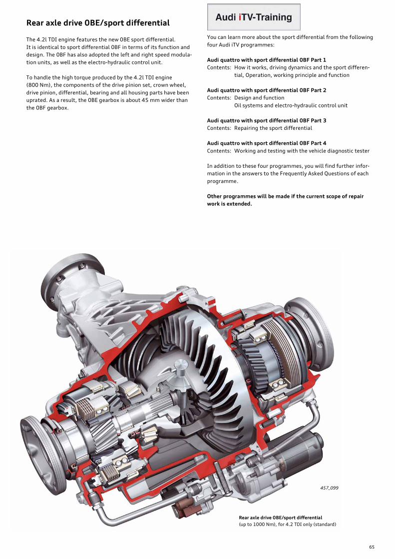
65
Rear axle drive 0BE/sport differential
The 4.2l TDI engine features the new 0BE sport differential.
It is identical to sport differential 0BF in terms of its function and
design. The 0BF has also adopted the left and right speed modula-
tion units, as well as the electro-hydraulic control unit.
To handle the high torque produced by the 4.2l TDI engine
(800 Nm), the components of the drive pinion set, crown wheel,
drive pinion, differential, bearing and all housing parts have been
uprated. As a result, the 0BE gearbox is about 45 mm wider than
the 0BF gearbox.
You can learn more about the sport differential from the following
four Audi iTV programmes:
Audi quattro with sport differential 0BF Part 1
Contents: How it works, driving dynamics and the sport differen-
tial, Operation, working principle and function
Audi quattro with sport differential 0BF Part 2
Contents: Design and function
Oil systems and electro-hydraulic control unit
Audi quattro with sport differential 0BF Part 3
Contents: Repairing the sport differential
Audi quattro with sport differential 0BF Part 4
Contents: Working and testing with the vehicle diagnostic tester
In addition to these four programmes, you will find further infor-
mation in the answers to the Frequently Asked Questions of each
programme.
Other programmes will be made if the current scope of repair
work is extended.
457_099
Rear axle drive 0BE/sport differential
(up to 1000 Nm), for 4.2 TDI only (standard)

66
Intelligent torque distribution
The Audi A8 ’10 will come equipped with the new "intelligent
torque distribution" system from Q3 2010 onwards.
Intelligent torque distribution is an enhanced version of the cur-
rent EPC function (electronic differential lock). Unlike the EPC sys-
tem, the electronic transverse lock is active when cornering and
intervenes before critical slip occurs at the wheels.
For this purpose, the control unit computes the load taken off the
wheels on the inside of the corner and the load on the wheels on
the outside of the corner when cornering. This calculation is essen-
tially based on the measurement data acquired by the steering
angle sensors and the transverse acceleration sensors. The ESP
control unit uses this information to determine the ideal brake
pressure for the wheels on the inside of the corner.
Intelligent torque distribution - how it works/function
A multiplying torque is produced when cornering by controlled
braking of the wheels on the inside of the corner. As a result, addi-
tional drive torque is directed to the wheels on the outside of the
corner. Cornering traction is significantly better. The vehicle is
capable for higher cornering speeds and handles with greater pre-
cision. Likewise, this greatly improves agility when steering into
corners and during steering manoeuvres.
As mentioned, the system reacts to the change in wheel load and
not to wheel slip. The necessary brake pressure of
5 - 15 bar is relatively low, minimising brake load and material
stress.
The intelligent torque distribution system offers driving dynamics
of the highest order with a minimum of system complexity and
high ride comfort.
Vehicles with the 0BC standard rear axle drive have intelligent
torque distribution on the front and rear axles. In vehicles with a
sport differential, intelligent torque distribution is effective only
on the front axle.
Basic principles
Basically, driving physics dictate that the maximum transmissible
drive torque becomes greater with increasing transverse accelera-
tion at the wheels on the outside of the corner, while decreasing to
the same extent at the inner wheels.
That is due to the effect of centrifugal force acting on the vehicle's
centre of gravity and its line of action towards the outside of the
corner. This results in what is known as "roll torque", which is
exerted on the wheels. This toll torque reduces the load on the
wheels on the inside of the corner and increases the load on the
wheels on the outside of the corner. Consequently, the wheels on
the inside of the corner are not able to transmit as much torque as
the wheels on the outside of the corner.
The open axle differentials distribute drive torque at a ratio of 1:1
to both wheels on an axle. If the maximum transmissible torque at
the driven wheel on the inside of the corner decreases, therefore,
the wheel on the outside of the corner will only be able to trans-
mit the same amount of torque – even though the greater effec-
tive wheel load would theoretically allow it to transmit
considerably more drive torque.
If the wheel on the inside of the corner loses drive torque, the
entire powertrain will lose drive torque.

67
457_104
457_109
457_108
457_107
457_106
457_105
Self-Study Programmes relevant to the Audi A8 ’10
This Self-Study Programme summarises all the information you
need to know about power transmission in the Audi A8 ’10. For
further information about the Audi A8 ’10, refer to the following
Self-Study Programmes.
SSP 456 Audi A8 ’10
- Body
- Passive/active safety
- Engine
- Suspension system
- Electrical system/air conditioning/infotainment
Order number: A10.5S00.60.20
SSP 458 Audi A8 ’10 Suspension system
- Front axle/rear axle
- adaptive air suspension
- Dynamic steering
- Brake system
Order number: A10.5S00.62.20
SSP 459 Audi A8 ’10 Onboard power supply and networking
- Topology
- FlexRay
- Light system
- LED headlight
Order number: A10.5S00.63.20
SSP 460 Audi A8 ’10 Convenience electronics and Audi tracking
assist
- Control unit with display in dash panel insert J285
- Convenience system control unit J393
- Background lighting
- Audi tracking assist
Order number: A10.5S00.64.20
SSP 461 Audi A8 ’10 Driver assistance systems
- New image processing system
- Camera control unit J852
- Intelligent light system with navigation assistance
- Image processing control unit J851
- Functions of the ACC Stop & Go image processing system
Order number: A10.5S00.65.20
SSP 462 Audi A8 ’10 Night vision assist
- Functions of the night vision assist system
- System operation and displays
- System components
- System overview
- Diagnostic functions and system calibration
Order number: A10.5S00.66.20

Audi Vorsprung durch Technik
AudiService Training
Audi A8 ’10 Power Transmission
Eight-speed Automatic Gearboxes 0BK and 0BLRear Axle Drives 0BF and 0BE – Sport Differential
All rights reserved. Technical
specifications subject to change
without notice.
Copyright
AUDI AG
I/VK-35
AUDI AG
D-85045 Ingolstadt
Technical status: 11/09
Printed in Germany
A10.5S00.61.20
Self-Study Programme 457
45
7


