Download - B904 Integration
John Coughlan , Tracker Electronics Integration , 12 April 2005
presented by John Coughlan RAL
B904 Integration
Pre-Series Manufacture
Final Production Plans
John Coughlan , Tracker Electronics Integration , 12 April 2005
B904 Integration Firstly, apologies if this has already been covered in 2 previous meetings and/or is stating the obvious…
…and approaching this problem from point of view of validating FED boards.
Scope : only considering OFF Detector Electronics i.e. crates in USC55.
Strategy : to have final Tracker DAQ system i.e. final racks destined for USC55 operational as test bed in B904
Schedule and Resources : need to identify one overall responsible for B904 hardware (CERN based). Subdivide tasks for hardware/firmware/software. Milestones.
Arrive at System Test with all final components for 2 partitions asap;
So many ‘new’ components still to be integrated… APVE, FMM, OptoFEC, OptoFED, LTC, TTCci, TTC splitter, CAEN CC, FRL…
Distinguish System Tests vs Acceptance Tests
FED System Test : Test 2? full crates together with final Tracker DAQ elements see above (and assoc S/W). Synchronisation.
FED Acceptance Test : Follows on from UK acceptance tests see next slide
Individual FEDs will be tested as far as possible with Opto inputs/SLINK at RAL. But using FED Testers not final system.
Require system at B904 for CMS to validate FEDs (and other components)
Envisage Full Crate of FEDs (Opto inputs or simu test frames) running continuously “soaking” with central Tracker DAQ
Q. CMS Acceptance / Validation Policy?
Either refill this crate with random sample of FEDs from batches or re test every FED.
Both are doable, question of logistics. Target of ~ 50 boards / month commencing October 2005.
FEDs go into storage at B904? awaiting installation in USC55.
John Coughlan , Tracker Electronics Integration , 12 April 2005
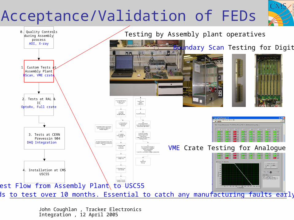
Acceptance/Validation of FEDs
1. Custom Tests atAssembly Plant
BScan, VME crate
3. Tests at CERNPrevessin 904
DAQ Integration
2. Tests at RAL &IC
OptoRx, Full crate
4. Installation at CMSUSC55
0. Quality Controlsduring Assembly
processAOI, X-ray
0. Assembly ProcessQuality Checks
E.g. AOI
2. Fit FrontPanelDeflector Bar
Jumpers
1. VisualInspection
Multimeter tests
3. Serial NrFit FP label & 2D
Bar code
4. Insert in CrateCheck formechanics
5. Power On CrateVerify LEDs
6. Boundary ScanSave results
7.Program EPROM(change Jumper)
8.Power Reset
buttonVerify LEDs
10.Test Serial EPROM
Load with Ser Nr, Date etcJumper for Write Protect
9.Test VME Access
11.Test FPGA loadingInsert CFlash Card
Power ResetVerify LEDs for Load Done
Flashing Clocks
12.Run Test Bench Programs:Exercise FPGA Registers
Read TemperaturesRead Voltages
Scan DACs and OptoRx settings capture data
13.Final Tests
Box up
Results of Operator Checks andProgrammable Tests should go to
Dbase
For details of tests and checksand acceptance criteria see
detailed diagrams
VME Crate Testing for Analogue
Test Flow from Assembly Plant to USC55500 boards to test over 10 months. Essential to catch any manufacturing faults early.
Boundary Scan Testing for Digital
Testing by Assembly plant operatives


