
FEBCO Product Catalog
Backflow PreventionFluid Control Product Catalog
FEBCOonline.com

FEBCO is an ISO 9001 Certified manufacturer of high quality fluid control products. For over 80 years
FEBCO has been committed to manufacturing excel-lence and innovative design and dedicated to the
improvement of our industry.
This catalog is presented to assist our customers, design engineers, municipal officials, contractors and
installers with the dimensional and technical data needed to use and specify FEBCO. Due to our com-
mitment to product refinement and improvement, specific details of our products may change. We make
every effort to ensure that our dimensions and techni-cal data are as accurate as possible. Please contact
your local FEBCO representative for our latest product information. A list of representatives as well as helpful,
in-depth information about our products can be found at our web site: www.FEBCOonline.com
We thank you, our customers, for your continued support and for making our success possible. The
employees and representatives of FEBCO look for-ward to serving you.
ISO 9001 Certified
Table of Contents
Section 1 — Single Check Valves Series 800 . . . . . . . . . . . . . 4" – 10" Detector Check for Automatic Fire Sprinkler Systems. . . . . . . . . . . . . . . . . . . . . . . . . . . . . . . . . 8
Series 406 . . . . . . . . . . . . . 2" Detector Check for Automatic Fire Sprinkler Systems . . . . . . . . . . . . . . . . . . . . . . . . . . . . . . . . . . . . . 9
Section 2 — Double Check Valve AssembliesSeries 850, LF850 . . . . . . . 1⁄2" – 2" Double Check Valve Assemblies . . . . . . . . . . . . . . . . . . . . . . . . . . . . . . . . . . . . . . . . . . . . 10 - 11
Series LF850 . . . . . . . . . . . 21⁄2" – 10" Double Check Valve Assemblies . . . . . . . . . . . . . . . . . . . . . . . . . . . . . . . . . . . . . . . . . . 12 - 13
Series 850U, LF850U . . . . . 1⁄2" – 2" Double Check Valve Assemblies w/Union End Ball Valves . . . . . . . . . . . . . . . . . . . . . . . . . 14 - 15
Series LF870V . . . . . . . . . . 21⁄2" – 8" Double Check Valve Assemblies . . . . . . . . . . . . . . . . . . . . . . . . . . . . . . . . . . . . . . . . . . . 16 - 17
Section 3 — Double Check Detector AssembliesSeries 856ST . . . . . . . . . . . 21⁄2" – 10" Double Check Detector Assemblies . . . . . . . . . . . . . . . . . . . . . . . . . . . . . . . . . . . . . . . . 18 - 19
Series 876VST . . . . . . . . . . 21⁄2" – 10" Double Check Detector Assemblies . . . . . . . . . . . . . . . . . . . . . . . . . . . . . . . . . . . . . . . . 20 - 21
Section 4 — Reduced Pressure Zone AssembliesSeries 825Y, LF825Y . . . . . 3⁄4" – 2" Reduced Pressure Zone Assemblies . . . . . . . . . . . . . . . . . . . . . . . . . . . . . . . . . . . . . . . . . 22 - 23
Series 825YA, LF825YA . . . 3⁄4" – 2" Reduced Pressure Zone Assemblies . . . . . . . . . . . . . . . . . . . . . . . . . . . . . . . . . . . . . . . . . 24 - 27
Series 860, LF860 . . . . . . . 1⁄2" – 2" Reduced Pressure Zone Assemblies . . . . . . . . . . . . . . . . . . . . . . . . . . . . . . . . . . . . . . . . . 28 - 29
Series LF860 . . . . . . . . . . . 21⁄2" – 10" Reduced Pressure Zone Assemblies . . . . . . . . . . . . . . . . . . . . . . . . . . . . . . . . . . . . . . . 30 - 31
Series 860U, LF860U . . . . . 1⁄2" – 2" Reduced Pressure Zone Assemblies w/Union End Ball Valves. . . . . . . . . . . . . . . . . . . . . . 32 - 33
Series LF880V . . . . . . . . . . 21⁄2" – 10" Reduced Pressure Zone Assemblies . . . . . . . . . . . . . . . . . . . . . . . . . . . . . . . . . . . . . . . 34 - 35
Section 5 — Reduced Pressure Detector AssembliesSeries 826YD . . . . . . . . . . . 21⁄2" – 10" Reduced Pressure Detector Assemblies . . . . . . . . . . . . . . . . . . . . . . . . . . . . . . . . . . . . 36 - 37
Section 6 — Vacuum BreakersSeries 710/715. . . . . . . . . . 1⁄2" – 2" Atmospheric Vacuum Breakers . . . . . . . . . . . . . . . . . . . . . . . . . . . . . . . . . . . . . . . . . . . . . 38 - 39
Series 765 . . . . . . . . . . . . . 1⁄2" – 2" Pressure Vacuum Breakers . . . . . . . . . . . . . . . . . . . . . . . . . . . . . . . . . . . . . . . . . . . . . . . . 40 - 41
Series LF767FR . . . . . . . . . 1⁄2" – 2" Freeze Resistant Pressure Vacuum Breakers. . . . . . . . . . . . . . . . . . . . . . . . . . . . . . . . . . . 42 - 43

Table of Contents
Section 7 — Accessories Series 601-P . . . . . . . . . . . 1⁄2" – 2" Air Gap Drains for Use with 860, 860U, LF860, LF860U . . . . . . . . . . . . . . . . . . . . . . . . . . . . . 44
Series 601-M . . . . . . . . . . . 1⁄2" – 2" Air Gap Drains for Use with 860, 860U, LF860, LF860U . . . . . . . . . . . . . . . . . . . . . . . . . . . . . 45
Series 601-M . . . . . . . . . . . 21⁄2" – 10" Air Gap Drain Kits for Use with the MasterSeries . . . . . . . . . . . . . . . . . . . . . . . . . . . . . . . . . . 46
Series AGD . . . . . . . . . . . . 3⁄4" – 2" and 21⁄2" – 10" Air Gap Drains for Use with Reduced Pressure Devices. . . . . . . . . . . . . . . . . . . 47
Series 611 . . . . . . . . . . . . . 21⁄2" – 10" Valve Setter Used with the MasterSeries . . . . . . . . . . . . . . . . . . . . . . . . . . . . . . . . . . . . 48 - 50
Series FPTC-1 . . . . . . . . . . 1⁄8" – 3⁄4" Thermostatic Freeze Relief . . . . . . . . . . . . . . . . . . . . . . . . . . . . . . . . . . . . . . . . . . . . . . . . . . . . 51
Series LF650A . . . . . . . . . . 1⁄2" – 2" “Y” Strainers. . . . . . . . . . . . . . . . . . . . . . . . . . . . . . . . . . . . . . . . . . . . . . . . . . . . . . . . . . . . . . . . 52
Series 758A . . . . . . . . . . . . 21⁄2" – 10" “Y” Strainers. . . . . . . . . . . . . . . . . . . . . . . . . . . . . . . . . . . . . . . . . . . . . . . . . . . . . . . . . . . . . . 53
Spool Adapter . . . . . . . . . . 4" – 8" DuraCheck to MasterSeries‚ Spacer Spool Adapter Kit . . . . . . . . . . . . . . . . . . . . . . . . . . . . . . . 54
Series LFTC-1 . . . . . . . . . . Full Port Test Cock . . . . . . . . . . . . . . . . . . . . . . . . . . . . . . . . . . . . . . . . . . . . . . . . . . . . . . . . . . . . . . . . . 55
TK-1 . . . . . . . . . . . . . . . . . . Backflow Preventer Test Kit . . . . . . . . . . . . . . . . . . . . . . . . . . . . . . . . . . . . . . . . . . . . . . . . . . . . . . . . . . 56
Section 8 — Irrigation SpecialtiesSeries FPHB-1 . . . . . . . . . . 3⁄4" – 1" Key Operated Wall Hydrants . . . . . . . . . . . . . . . . . . . . . . . . . . . . . . . . . . . . . . . . . . . . . . . . . . . 57
Series LF622 . . . . . . . . . . . 1⁄2" – 2" Full Port Ball Valves . . . . . . . . . . . . . . . . . . . . . . . . . . . . . . . . . . . . . . . . . . . . . . . . . . . . . . 58 - 59
Section 9 — Flow Charts . . . . . . . . . . . . . . . . . . . . . . . . . . . . . . . . . . . . . . . . . . . . . . . . . . . . . . . . . . . . . . . . . . . . . . . . . . . . . . . . . . . . . . . . . . . . . . . . . . 60 - 71
Note: FEBCO product specifications in U.S. customary units and metric are approximate and are provided for reference only. For precise measurements, please contact FEBCO Technical Service. FEBCO reserves the right to change or modify product design, construction, specifications, or materials with-out prior notice and without incurring any obligation to make such changes and modifications on FEBCO products previously or subsequently sold.
Why Work with FEBCO?
Safeguarding the drinking water supply is critical to protecting human health. For 50+ years FEBCO has designed and manufactured innovative and patented assemblies for this critical purpose. FEBCO’s backflow prevention assemblies, which prevent the backward flow of contaminated water into the potable water supply, are reliable and easily serviced. What’s more, they offer one of the lowest total installed costs in the industry.
From FEBCO’s earliest days, experienced engineers have combined expert knowledge, technological advances, industry innovation, and broad manufacturing experience to design and manufacture one of the widest lines of top-quality backflow prevention assem-blies available.
FEBCO works closely with municipalities, engineers, architects, and contractors to solve their unique backflow prevention issues, and provides educational materials to the general public for building awareness around the importance of safeguarding potable water.
Why work with FEBCO? Simple. Superior designs, innovative technology, state-of-the-art manufacturing facilities, and a commitment to keeping all drinking water clean and safe with reliable and trusted backflow prevention assemblies.
Lead Free TransitionWith the changeover to lead free in the United States that became effective January 4, 2014, lead free backflow prevention devices are required in certain applications and/or settings. The FEBCO backflow preventer line includes top-quality, fully-tested Lead Free* versions of our standard backflow products.
Standard Material Products (not Lead Free*) CONTAIN MORE THAN 0.25% LEAD. Effective January 4, 2014, it is illegal to use this product in any plumbing system providing water for human consumption, such as drinking or dishwashing, in the United States.
Before installing standard material product, consult your local water authority, building and plumbing codes.
Industry TermsBackpressure: Pressure, higher than the supply pressure, caused by a pump, elevated tank, boiler, or other means that can cause backflow.
Backsiphonage: Backflow caused by negative or reduced pressure in the supply piping.
Cross-connection: A connection or potential connection between any part of the potable water system and another environment where undesirable substances could enter the potable water system. Contaminated or undesirable substances can include gases, liquids, or solids, such as chemicals, waste products, steam, water from other sources (potable or non-potable), or any other mat-ter that can change the color of or add odor to the water. Bypass arrangements, jumper connections, removable sections, swivel or changeover assemblies, or any other temporary or permanent connecting arrangement where backflow can occur are considered cross-connections.
* The wetted surface of this product contacted by consumable water contains less than 0.25% of lead by weight.
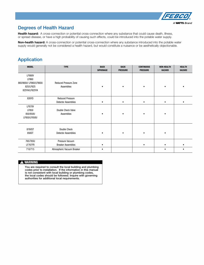
MODEL TYPE BACK BACK CONTINUOUS NON-HEALTH HEALTH SIPHONAGE PRESSURE PRESSURE HAZARD HAZARD
LF880V LF860 860/860U/ LF860/LF860U Reduced Pressure Zone 825/LF825 Assemblies • • • • • 825YA/LF825YA
826YD Reduced Pressure Detector Assemblies • • • • •
LF870V LF850 Double Check Valve 850/850U Assemblies • • • • LF850/LF850U
876VST Double Check 856ST Detector Assemblies • • • •
765/765U Pressure Vacuum LF767FR Breaker Assemblies • • • •
710/715 Atmospheric Vacuum Breaker • • •
Degrees of Health HazardHealth hazard: A cross-connection or potential cross-connection where any substance that could cause death, illness, or spread disease, or have a high probability of causing such effects, could be introduced into the potable water supply.
Non-health hazard: A cross-connection or potential cross-connection where any substance introduced into the potable water supply would generally not be considered a health hazard, but would constitute a nuisance or be aesthetically objectionable.
Application
You are required to consult the local building and plumbing codes prior to installation. If the information in this manual is not consistent with local building or plumbing codes, the local codes should be followed. Inquire with governing authorities for additional local requirements.
WARNING!
1S
ingle C
heck Valves
8 For additional information, reference literature ES-F-800. Flow Charts on p. 60.
Dimensions — Weights
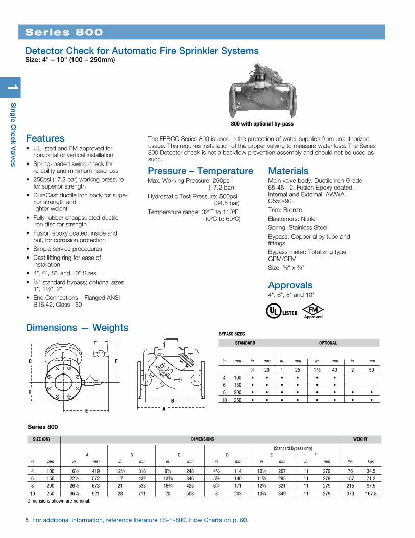
The FEBCO Series 800 is used in the protection of water supplies from unauthorized usage. This requires installation of the proper valving to measure water loss. The Series 800 Detector check is not a backflow prevention assembly and should not be used as such.
800 with optional by-pass
Features• UL listed and FM approved for
horizontal or vertical installation.• Spring-loaded swing check for
reliability and minimum head loss• 250psi (17.2 bar) working pressure
for superior strength• DuraCast ductile iron body for supe-
rior strength and lighter weight
• Fully rubber encapsulated ductile iron disc for strength
• Fusion epoxy coated, inside and out, for corrosion protection
• Simple service procedures• Cast lifting ring for ease of
installation• 4", 6", 8", and 10" Sizes• 3⁄4" standard bypass; optional sizes
1", 11⁄2", 2"• End Connections – Flanged ANSI
B16.42, Class 150
SIZE (DN) DIMENSIONS WEIGHT
(Standard Bypass only) A B C D E F in. mm in. mm in. mm in. mm in. mm in. mm in. mm lbs. kgs.
4 100 161⁄2 419 121⁄2 318 93⁄4 248 41⁄2 114 101⁄2 267 11 279 76 34.5 6 150 221⁄2 572 17 432 135⁄8 346 51⁄2 140 115⁄8 295 11 279 157 71.2 8 200 261⁄2 673 21 533 163⁄4 425 63⁄4 171 125⁄8 321 11 279 215 97.5 10 250 361⁄4 921 28 711 20 508 8 203 133⁄4 349 11 279 370 167.8Dimensions shown are nominal.
E
C
D
F
B
A
STANDARD OPTIONAL
in. mm in. mm in. mm in. mm in. mm
3⁄4 20 1 25 11⁄2 40 2 50 4 100 • • • • • • 6 150 • • • • • • 8 200 • • • • • • • • 10 250 • • • • • • • •
Materials Main valve body: Ductile iron Grade 65-45-12, Fusion Epoxy coated, Internal and External, AWWA C550-90Trim: BronzeElastomers: NitrileSpring: Stainless SteelBypass: Copper alloy tube and fittingsBypass meter: Totalizing type GPM/CFMSize: 5⁄8" x 3⁄4"
Approvals4", 6", 8" and 10"
Series 800
Detector Check for Automatic Fire Sprinkler SystemsSize: 4" – 10" (100 – 250mm)
Pressure – TemperatureMax. Working Pressure: 250psi (17.2 bar)Hydrostatic Test Pressure: 500psi (34.5 bar)Temperature range: 32ºF to 110ºF (0ºC to 60ºC)
BYPASS SIZES
Series 800

For additional information, reference literature ES-F-406. Flow Chart on p. 60. 9
Series 406
Detector Check for Automatic Fire Sprinkler SystemsSize: 2" (50mm)
Sin
gle
Che
ck V
alve
s1
9" (230mm)
133⁄8" (340mm)
17" (432mm)
21⁄2" (64mm)
3⁄4" (19mm) IPS (TWO PLACES)
81⁄2" (216mm)
(2) 3⁄4" DIA. HOLES (19mm)
6" (152mm)
41⁄2" (114mm)
406
OperationIn a non-flowing condition, the mainline check and by-pass check are closed and the meter is stopped. When water begins to flow, the bypass check opens and the meter begins to register. When the pressure drop across the valve approximates 1.5psi (10.3 kPa), the mainline check opens and allows full flow of water.
The bypass meter and check remain operating and open at all flow rates.
Dimensions
The FEBCO Series 406 Detector Check is designed for automatic fire sprinkler systems (non-potable applications).
Features• Meter detects leakage and/or
theft of water from Automatic Fire Sprinkler Systems
• Can be installed horizontally or verti-cally (up or down)
• Center-stem-guided, spring-loaded check for more positive seating
• Replaceable bronze seat ring• Reversible seat disc for ease of ser-
vice• Bronze body and cover• End Detail – 2 Bolt Meter Flange
Pressure – TemperatureSizes: Mainline: 2" (50mm) Bypass: ¾" (20mm) IPSMaximum Working Pressure: 175psi (12.1 bar)Hydrostatic Test Pressure: 350psi (24.1 bar)Temperature Range: 32ºF to 110ºF (0ºC - 43ºC)
Materials Main Valve Body: BronzeSeat Ring: BronzeDisc Holder: DelrinSpring: Stainless SteelBy-pass Meter: Bronze Totalizing Water Meter Optional (gpm or cfm)
NOTICEInquire with governing authorities for local installation requirements.

2D
oub
le Check V
alve Assem
blies
10 For additional information, reference literature ES-F-850S and ES-LF-850S. Flow Charts on p. 60.
Series 850/LF850
Double Check Valve AssembliesSize: 1⁄2" – 2" (15 – 50mm)
850/LF850
1015 B64.5
Pressure – Temperature Max. Working Pressure: 175psi (12.1 bar)Hydrostatic Test Press: 350psi (24.1 bar)Temperature Range: 32°F to 140°F (0°C to 60°C)
The FEBCO Series 850 Double Check Valve Assemblies are designed for non-health hazard applications. End Connections – NPT ANSI/ASME B1.20.1. They are designed to protect drinking water supplies from dangerous cross connections in accordance with national plumbing codes and water authority requirements for non-potable service applications such as irrigation, fireline, or industrial processing.
MaterialsValve Body: Bronze Elastomers: Silicone Springs: Stainless Steel
Models• Wye - Strainer
Approvals – Standards• ANSI/AWWA Conformance
(C510-92) • Approved by the Foundation for Cross-
Connection Control and Hydraulic Research at the University of Southern California.
The FEBCO Series LF850 Double Check Valve Assemblies are designed for non-health hazard applications. The LF850S features Lead Free* construction to comply with Lead Free* installation requirements. End Connections – NPT ANSI / ASME B1.20.1. The Lead Free* Double Check Valve Assemblies shall comply with state codes and standards, where appli-cable, requiring reduced lead content.
MaterialsValve Body: Lead Free* cast copper silicon alloy Elastomers: Silicone Springs: Stainless Steel
Models • LF850 - Standard Assembly with Ball
Valves
Approvals• ANSI/AWWA Conformance
(C510-92) • Approved by the Foundation for
Cross-Connection Control and Hydraulic Research at the University of Southern California.
* The wetted surface of this product contacted by consumable water contains less than 0.25% of lead by weight.
LEAD FREE*
1015 B64.5
Do
uble
Che
ck V
alve
Ass
emb
lies
2
11
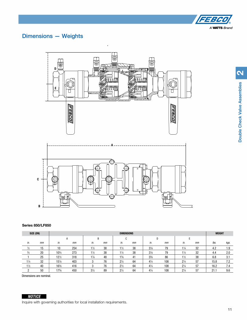
Dimensions — Weights
SIZE (DN) DIMENSIONS WEIGHT
A B C D E in. mm in. mm in. mm in. mm in. mm in. mm lbs. kgs.
1⁄2 15 10 254 11⁄2 38 11⁄2 38 31⁄8 79 11⁄4 32 4.2 1.9 3⁄4 20 103⁄4 273 11⁄2 38 11⁄2 38 31⁄8 79 11⁄4 32 4.4 2.0 1 25 121⁄2 318 17⁄8 48 15⁄8 41 33⁄8 86 11⁄2 38 6.8 3.1 11⁄4 32 157⁄8 403 3 76 21⁄2 64 41⁄4 108 21⁄4 57 15.8 7.2 11⁄2 40 163⁄8 416 3 76 21⁄2 64 41⁄4 108 21⁄4 57 16.2 7.4 2 50 175⁄8 450 31⁄2 89 21⁄2 64 41⁄4 108 21⁄4 57 21.1 9.6
D
E
C
B
Series 850/LF850
A
NOTICEInquire with governing authorities for local installation requirements.
Dimensions are nominal.

2D
oub
le Check V
alve Assem
blies
12 For additional information, reference literature ES-F-850L Flow Charts on p. 61.
The FEBCO Master Series® 850 Double Check Valve Assemblies are designed for non-health hazard applica-tions. End Connections – Flanged ANSI B16.1 Class 125. The FEBCO MasterSeries LF850 Double Check Assembly is specifically designed to protect against possible backpressure and backsiphonage conditions for non-health hazard (i.e., pollutant) application in accordance with Local Governing Water Utility Code. This Backflow Assembly is primarily used on potable drinking water systems where Local Governing Code mandates protection from non-potable quality water being pumped or siphoned back into the potable water system.
The LF850 features Lead Free* construction to comply with low lead installation requirements. The Lead Free* Double Check Assemblies shall comply with state codes and standards, where applicable, requiring reduced lead content.
MasterSeries® LF850
Double Check Valve AssembliesSize: 21⁄2" – 10" (65 – 250mm)
850 Double Check Assembly
LEAD FREE*
Features• Inline Serviceable Assembly• No Special Tools Required for Servicing• Captured Modular Spring Assembly• Reversible & Replaceable Discs• Field Replaceable Seats• Ductile Iron Valve Body Design• Stainless Steel Check Components• Winterization feature with disc retainers and valve body drain ports• Clapper Check Assembly• Commonality between 1st & 2nd Check Components• Captured O-ring Design
Pressure-TemperatureMax. Working Pressure: 175psi (12.1 bar)
Min. Working Pressure: 10psi (0.7 bar)
Hydrostatic Test Pressure: 350psi (24.1 bar)
Hydrostatic Safety Pressure: 700psi (48.3 bar)
Temperature Range: 33°F - 140°F (0.5°C - 60°C) Continuous
* The wetted surface of this product contacted by consumable water contains less than 0.25% of lead by weight.
OptionsOSY: UL/FM Approved OS&Y Gate
Valves (ANSI/AWWA C515 Compliant)
NRS: Non-Rising Stem Gate Valves (ANSI/AWWA C509 Compliant)
LG: Less Shut-off valves; This is NOT an APPROVED ASSEMBLY
Example Ordering Descriptions:
4” LF850-OSY - Valve Assembly fitted with OS&Y Shutoff Valves
4” LF850-NRS - Valve Assembly fittedwith NRS Shutoff Valves
MaterialsBelow is a general materials list of the Model LF850. All assemblies size 21⁄2" through 10" is similar in materials and construction. Please contact your local FEBCO Representative if you require fur-ther information.
Main Valve Body: Ductile iron Grade 65-45-12
Coating: Fusion epoxy coated internal and external AWWA C550
Shutoff Valves: NRS resilient wedge gate valves AWWA C509 (Standard) OSY resilient wedge gate valves AWWA C515 (UL/FM)Check Seats: Stainless Steel
Disc Holder: Stainless Steel
Elastomer Disc: Silicone
Spring: Stainless Steel
Clamp: AWWA C606 (10" Only)
Approvals• Approved by the Foundation for
Cross-Connection Control and Hydraulic Research at The University of Southern California (FCCCHR-USC)
• ASSE 1015 Listed• UL Classified (US & Canada)†
• FM Approved†
• IAPMO• CSA Listed• AWWA Standard C510 Compliant• End Connections: Compliant to
ASME B16.1 Class 125 & AWWA Class D Flange
† Assembly configured with UL/FM Approved OS&Y RW Gate Valves. Less gate valve assemblies are not UL/FM approved configurations.
1015†
B64.5
†
SIZE (DN) DIMENSIONS WEIGHT
A B C* D G H NRS OS&Y in. mm in. mm in. mm in. mm in. mm in. mm in. mm lbs. kgs. lbs. kgs.
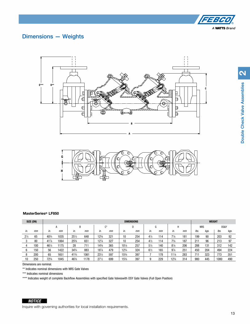
21⁄2 65 403⁄4 1035 251⁄2 648 125⁄8 321 10 254 41⁄2 114 71⁄8 181 199 90 203 92 3 80 417⁄8 1064 255⁄8 651 127⁄8 327 10 254 41⁄2 114 73⁄8 187 211 96 213 97 4 100 461⁄4 1175 28 711 143⁄8 365 101⁄8 257 51⁄2 140 81⁄8 206 288 131 312 142 6 150 56 1422 343⁄4 883 187⁄8 479 123⁄4 324 61⁄2 165 97⁄8 251 450 204 494 224 8 200 65 1651 413⁄4 1061 231⁄2 597 155⁄8 397 7 178 111⁄8 283 711 323 773 351 10 250 725⁄8 1845 463⁄8 1178 271⁄2 699 155⁄8 397 9 229 123⁄8 314 980 445 1080 490
Do
uble
Che
ck V
alve
Ass
emb
lies
2
13
Dimensions — Weights
G
HH
G
A
B
CCD
E*** D**
A
B
C
MasterSeries® LF850
NOTICEInquire with governing authorities for local installation requirements.
Dimensions are nominal.
** Indicates nominal dimensions with NRS Gate Valves
*** Indicates nominal dimensions
**** Indicates weight of complete Backflow Assemblies with specified Gate Valveswith OSY Gate Valves (Full Open Position)

2D
oub
le Check V
alve Assem
blies
14 For additional information, reference literature ES-F-850U and ES-F-LF850U. Flow Charts on p. 61.
The FEBCO Series LF850U Double Check Valve Assemblies are designed for non-health hazard applications. End Connections – NPT ANSI/ASME B1.20.1. The LF850U features Lead Free* construction to comply with Lead Free* installation requirements. End Connections – NPT ANSI/ASME B1.20.1. The Lead Free* Double Check Valve Assemblies with Union End Ball Valves shall comply with state codes and standards, where applicable, requiring reduced lead content.
Series 850U/LF850U
Double Check Valve Assemblies with Union End Ball ValvesSize: 1⁄2" – 2" (15 – 50mm)
850U/LF850U
Pressure – TemperatureMax. Working Pressure: 175psi (12.1 bar)
Hydrostatic Test Press: 350psi (24.1 bar)
Temperature Range: 32°F to 140°F (0°C to 60°C)
1015 B64.5
* The wetted surface of this product contacted by consumable water contains less than 0.25% of lead by weight.
MaterialsValve Body: BronzeElastomers: SiliconeSprings: Stainless Steel
LEAD FREE*
Approvals – Standards• ANSI/AWWA Conformance (C510-92) • Approved by the Foundation
for Cross-Connection Control and Hydraulic Research at the University of Southern California.
The FEBCO Series 850U Double Check Valve Assemblies are designed for non-health hazard applications. Series 850U are designed to protect drinking water supplies from dangerous cross-connections in accordance with national plumbing codes and water authority requirements for non-potable service applications such as irrigation, fireline, or industrial processing. End Connections – NPT ANSI/ASME B1.20.1.
Materials Valve Body: Bronze Elastomers: Silicone Springs: Stainless Steel
Approvals – Standards• ANSI/AWWA Conformance (C510-92) • Approved by the Foundation
for Cross-Connection Control and Hydraulic Research at the University of Southern California.
1015 B64.5

Do
uble
Che
ck V
alve
Ass
emb
lies
2
15
Dimensions — Weights
SIZE (DN) DIMENSIONS WEIGHT
A B C D E in. mm in. mm in. mm in. mm in. mm in. mm lbs. kgs.
1⁄2 15 11 299 11⁄2 38 11⁄2 38 31⁄8 79 11⁄4 32 4.2 1.9 3⁄4 20 121⁄2 318 11⁄2 38 11⁄2 38 31⁄8 79 11⁄4 32 5.1 2.3 1 25 145⁄8 372 17⁄8 48 15⁄8 41 33⁄8 86 11⁄2 38 7.7 3.5 11⁄4 32 181⁄4 464 3 76 21⁄2 64 41⁄4 108 21⁄4 57 14.9 6.8 11⁄2 40 187⁄8 479 3 76 21⁄2 64 41⁄4 108 21⁄4 57 18.0 8.2 2 50 201⁄2 521 31⁄2 89 21⁄2 64 41⁄4 108 21⁄4 57 24.1 10.9Dimensions are nominal.
D
E
A
C
B
SERIES 850U/LF850U
NOTICEInquire with governing authorities for local installation requirements.
2D
oub
le Check V
alve Assem
blies
16 For additional information, reference literature ES-LF-870V. Flow Charts on p. 62.
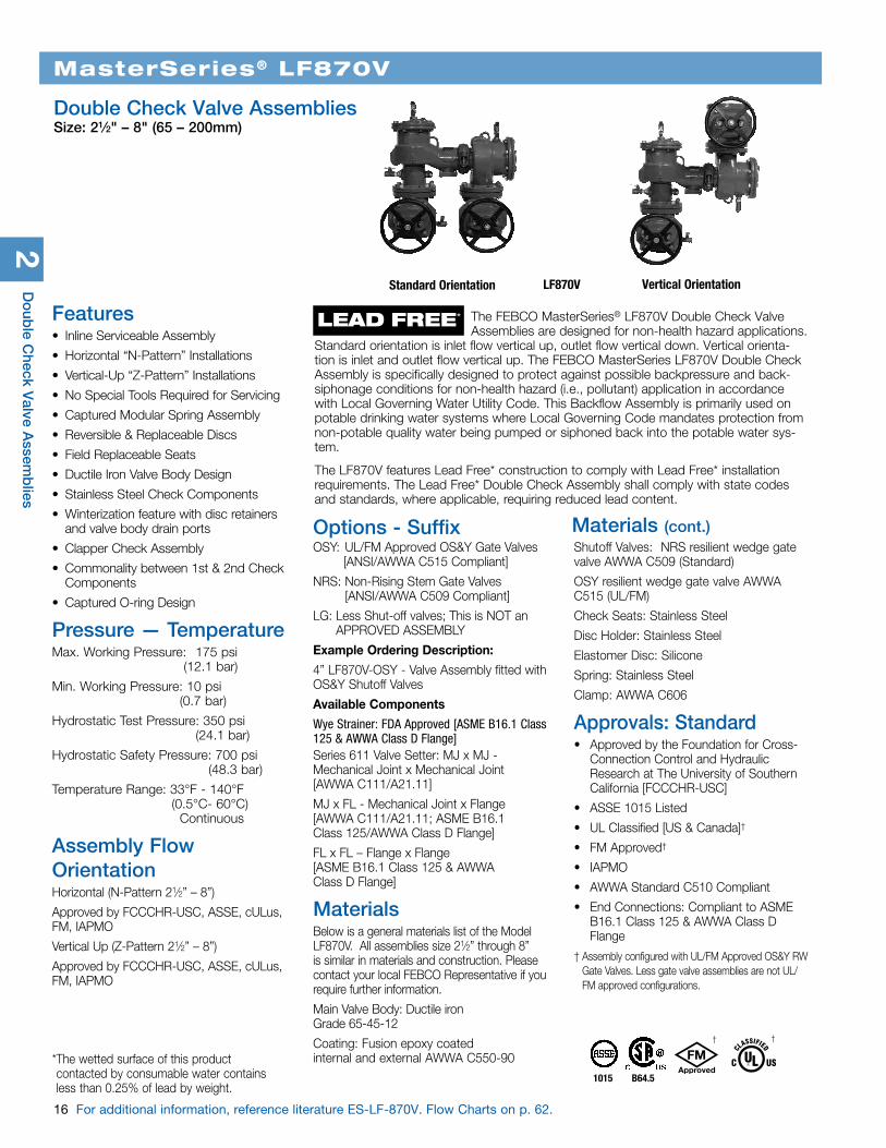
The FEBCO MasterSeries® LF870V Double Check Valve Assemblies are designed for non-health hazard applications. Standard orientation is inlet flow vertical up, outlet flow vertical down. Vertical orienta-tion is inlet and outlet flow vertical up. The FEBCO MasterSeries LF870V Double Check Assembly is specifically designed to protect against possible backpressure and back-siphonage conditions for non-health hazard (i.e., pollutant) application in accordance with Local Governing Water Utility Code. This Backflow Assembly is primarily used on potable drinking water systems where Local Governing Code mandates protection from non-potable quality water being pumped or siphoned back into the potable water sys-tem.
The LF870V features Lead Free* construction to comply with Lead Free* installation requirements. The Lead Free* Double Check Assembly shall comply with state codes and standards, where applicable, requiring reduced lead content.
MasterSeries® LF870V
Double Check Valve AssembliesSize: 21⁄2" – 8" (65 – 200mm)
LF870VStandard Orientation
1015 B64.5
† †
Features• Inline Serviceable Assembly
• Horizontal “N-Pattern” Installations
• Vertical-Up “Z-Pattern” Installations
• No Special Tools Required for Servicing
• Captured Modular Spring Assembly
• Reversible & Replaceable Discs
• Field Replaceable Seats
• Ductile Iron Valve Body Design
• Stainless Steel Check Components
• Winterization feature with disc retainers and valve body drain ports
• Clapper Check Assembly
• Commonality between 1st & 2nd Check Components
• Captured O-ring Design
Pressure — TemperatureMax. Working Pressure: 175 psi (12.1 bar)
Min. Working Pressure: 10 psi (0.7 bar)
Hydrostatic Test Pressure: 350 psi (24.1 bar)
Hydrostatic Safety Pressure: 700 psi (48.3 bar)
Temperature Range: 33°F - 140°F (0.5°C- 60°C) Continuous
Assembly Flow OrientationHorizontal (N-Pattern 21⁄2” – 8”)
Approved by FCCCHR-USC, ASSE, cULus, FM, IAPMO
Vertical Up (Z-Pattern 21⁄2” – 8”)
Approved by FCCCHR-USC, ASSE, cULus, FM, IAPMO
Options - SuffixOSY: UL/FM Approved OS&Y Gate Valves
[ANSI/AWWA C515 Compliant]
NRS: Non-Rising Stem Gate Valves [ANSI/AWWA C509 Compliant]
LG: Less Shut-off valves; This is NOT an APPROVED ASSEMBLY
Example Ordering Description:
4” LF870V-OSY - Valve Assembly fitted with OS&Y Shutoff Valves
Available Components
Wye Strainer: FDA Approved [ASME B16.1 Class 125 & AWWA Class D Flange]Series 611 Valve Setter: MJ x MJ - Mechanical Joint x Mechanical Joint [AWWA C111/A21.11]
MJ x FL - Mechanical Joint x Flange [AWWA C111/A21.11; ASME B16.1 Class 125/AWWA Class D Flange]
FL x FL – Flange x Flange [ASME B16.1 Class 125 & AWWA Class D Flange]
MaterialsBelow is a general materials list of the Model LF870V. All assemblies size 21⁄2” through 8” is similar in materials and construction. Please contact your local FEBCO Representative if you require further information.
Main Valve Body: Ductile iron Grade 65-45-12
Coating: Fusion epoxy coated internal and external AWWA C550-90
LEAD FREE*
* The wetted surface of this product contacted by consumable water contains less than 0.25% of lead by weight.
Shutoff Valves: NRS resilient wedge gate valve AWWA C509 (Standard)
OSY resilient wedge gate valve AWWA C515 (UL/FM)
Check Seats: Stainless Steel
Disc Holder: Stainless Steel
Elastomer Disc: Silicone
Spring: Stainless Steel
Clamp: AWWA C606
Approvals: Standard• Approved by the Foundation for Cross-
Connection Control and Hydraulic Research at The University of Southern California [FCCCHR-USC]
• ASSE 1015 Listed
• UL Classified [US & Canada]†
• FM Approved†
• IAPMO
• AWWA Standard C510 Compliant
• End Connections: Compliant to ASME B16.1 Class 125 & AWWA Class D Flange
† Assembly configured with UL/FM Approved OS&Y RW Gate Valves. Less gate valve assemblies are not UL/FM approved configurations.
Vertical Orientation
Materials (cont.)

Do
uble
Che
ck V
alve
Ass
emb
lies
2
17
Dimensions — Weights
Model LF870V Standard Orientation Model LF870V Vertical Orientation
K
BA
G
F
C
E
E1
J
F
C
G
B
M
K
SIZE (DN) DIMENSIONS WEIGHT****
A B C D E F G H I** J*** NRS OSY
in. mm in. mm in. mm in. mm in. mm in. mm in. mm in. mm in. mm in. mm in. mm lbs. kg. lbs. kg.
21⁄2 65 253⁄4 654 121⁄2 318 61⁄4 159 241⁄4 616 165⁄8 422 135⁄8 346 271⁄4 692 31⁄2 89 125⁄8 321 163⁄8 416 197 89 201 91
3 80 253⁄4 654 121⁄2 318 61⁄4 159 241⁄4 629 165⁄8 422 141⁄8 359 281⁄4 718 33⁄4 95 127⁄8 327 221⁄4 565 223 101 227 103
4 100 277⁄8 708 14 356 7 178 263⁄4 680 173⁄4 451 151⁄2 394 31 787 41⁄2 114 143⁄8 365 231⁄4 591 320 145 332 151
6 150 321⁄4 819 16 406 8 203 321⁄4 819 215⁄8 548 185⁄8 473 371⁄4 946 51⁄2 140 187⁄8 479 301⁄8 765 492 223 512 232
8 200 371⁄2 953 181⁄2 470 91⁄4 235 363⁄8 324 247⁄8 632 203⁄4 527 411⁄2 1054 63⁄4 172 231⁄2 597 373⁄4 959 782 355 810 367
Dimensions are nominal.
** Indicates nominal dimensions with NRS Gate Valves
*** Indicates nominal dimensions with OSY Gate Valves (Full Open Position)
**** Indicates weight of complete Backflow Assemblies with specified Gate Valves
10" sizes are available in standard materials. Consult factory.
SERIES LF870V
NOTICEInquire with governing authorities for local installation requirements.

3D
oub
le Check D
etector A
ssemb
lies
18 For additional information, reference literature ES-F-856ST. Flow Charts on p. 63.
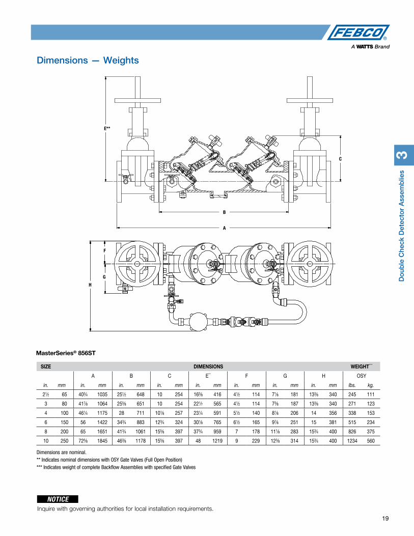
MasterSeries® 856ST
Double Check Detector Backflow Prevention AssembliesSize: 21⁄2" – 10" (65 – 250mm)
856STThe FEBCO MasterSeries 856ST Double Check Detector Assembly is specifically designed to protect against possible backpressure and backsiphonage conditions for non-health hazard (i.e., pollutant) application in accordance with Local Governing Water Utility Code. This Backflow Assembly is primarily used on potable drinking water systems and fire sprinkler systems, where Local Governing Code mandates protection from non-potable quality water being pumped or siphoned back into the potable water system. This assembly is designed to protect drinking water supplies from dangerous cross-connections in accordance with national plumbing codes and water authority requirements for non-potable service applications such as irrigation, fireline, or industrial processing.
FeaturesMain Valve:• Inline Serviceable Assembly• No Special Tools Required for
Servicing• Captured Modular Spring Assembly• Reversible & Replaceable Discs• Field Replaceable Seats• Ductile Iron Valve Body Design• Stainless Steel Check Components• Winterization feature with disc
retainers and valve body drain ports• Clapper Check Assembly• Commonality between 1st & 2nd
Check Components• Captured O-ring Design
Auxiliary Bypass:• Compact Bypass Design; Remains
within Main Valve Assembly Profile• Inline Serviceable 3⁄4" Backflow
Assembly• No Special Tools Required for
Servicing• Field Replaceable Seats & Discs• Detect Potential Underground Water
Leaks• Detect Unauthorized Water Usage
Pressure – Temperature Max. Working Pressure: 175psi (12.1 bar)
Min. Working Pressure: 10psi (0.7 bar)
Hydrostatic Test Pressure: 350psi (24.1 bar)
Hydrostatic Safety Pressure: 700psi (48.3 bar)
Temperature Range: 33°F - 140°F (0.5°C- 60°C) Continuous
Options - Suffix OSY: UL/FM Approved OS&Y Gate
Valves [ANSI/AWWA C515 Compliant]
NRS: Non-Rising Stem Gate Valves [ANSI/AWWA C509 Compliant]
LG: Less Shut-off valves; This is NOT an APPROVED ASSEMBLY
Example Ordering Description:
4” LF870V-OSY - Valve Assembly fitted with OS&Y Shutoff Valves
Available Components Wye Strainer: FDA Approved [ASME B16.1 Class 125 & AWWA Class D Flange]Series 611 Valve Setter: MJ x MJ - Mechanical Joint x Mechanical Joint [AWWA C111/A21.11] MJ x FL - Mechanical Joint x Flange [AWWA C111/A21.11; ASME B16.1 Class 125/AWWA Class D Flange]FL x FL – Flange x Flange [ASME B16.1 Class 125 & AWWA Class D Flange]
Assembly Flow Orientation Horizontal (N-Pattern 21⁄2” – 8”)
Approved by FCCCHR-USC, ASSE, cULus, FM, IAPMO
Vertical Up (Z-Pattern 21⁄2” – 8”)
Approved by FCCCHR-USC, ASSE, cULus, FM, IAPMO
Materials Below is a general materials list of the Model 856ST. All assemblies size 21⁄2” through 10” is similar in materials and construction.
Main Valve Body: Ductile iron Grade 65-45-12
Coating: Fusion epoxy coated internal and external AWWA C550-90
Shutoff Valves: NRS resilient wedge gate valve AWWA C509 (Standard)
OSY resilient wedge gate valve AWWA C515 (UL/FM)
Check Seats: Stainless Steel
Disc Holder: Stainless Steel
Elastomer Disc: Silicone
Spring: Stainless Steel
Clamp: AWWA C606
Please contact your local FEBCO Representative if you require further infor-mation.
Approvals – Standards• Approved by the Foundation for
Cross-Connection Control and Hydraulic Research at The University of Southern California [FCCCHR-USC]
• ASSE 1015 Listed• UL Classified [US & Canada]†
• FM Approved †
• IAPMO• AWWA Standard C510 Compliant• End Connections: Compliant to
ASME B16.1 Class 125 & AWWA Class D Flange
† Assembly configured with UL/FM Approved OS&Y RW Gate Valves. Less gate valve assemblies are not UL/FM approved configurations.
1015
† †
Do
uble
Che
ck D
etec
tor
Ass
emb
lies
3
19
Dimensions — Weights
SIZE DIMENSIONS WEIGHT***
A B C E** F G H OSY
in. mm in. mm in. mm in. mm in. mm in. mm in. mm in. mm lbs. kg.
21⁄2 65 403⁄4 1035 251⁄2 648 10 254 163⁄8 416 41⁄2 114 71⁄8 181 133⁄8 340 245 111
3 80 417⁄8 1064 255⁄8 651 10 254 221⁄7 565 41⁄2 114 73⁄8 187 133⁄8 340 271 123
4 100 461⁄4 1175 28 711 101⁄8 257 231⁄4 591 51⁄2 140 81⁄8 206 14 356 338 153
6 150 56 1422 343⁄4 883 123⁄4 324 301⁄8 765 61⁄2 165 97⁄8 251 15 381 515 234
8 200 65 1651 413⁄4 1061 155⁄8 397 373⁄4 959 7 178 111⁄8 283 153⁄4 400 826 375
10 250 725⁄8 1845 463⁄8 1178 155⁄8 397 48 1219 9 229 123⁄8 314 153⁄4 400 1234 560
Dimensions are nominal. ** Indicates nominal dimensions with OSY Gate Valves (Full Open Position)*** Indicates weight of complete Backflow Assemblies with specified Gate Valves
MasterSeries® 856ST
NOTICEInquire with governing authorities for local installation requirements.
A
B
C
D
G
F
E
E**
A
H
G
F
B
C

3D
oub
le Check D
etector A
ssemb
lies
20 For additional information, reference literature ES-F-876VST. Flow Charts on p. 63.
The FEBCO MasterSeries 876VST Double Check Detector Assembly is specifically designed to protect against possible backpressure and backsiphonage conditions for non-health hazard (i.e., pollutant) application in accordance with Local Governing Water Utility Code.
This Backflow Assembly is designed to protect drinking water supplies from dan-gerous cross-connections in accordance with national plumbing codes and water authority requirements for non-potable service applications such as irrigation, fire line, or industrial processing.
MasterSeries® 876VST
Double Check Detector Backflow Prevention AssembliesSize: 21⁄2" – 10" (65 – 250mm)
876VST Vertical OrientationStandard Orientation
FeaturesMain Valve: • Inline Serviceable Assembly• Horizontal “N-Pattern” Installations• Vertical-Up “Z-Pattern” Installations• No Special Tools Required for
Servicing• Captured Modular Spring Assembly• Reversible & Replaceable Discs• Field Replaceable Seats• Ductile Iron Valve Body Design• Stainless Steel Check Components• Winterization feature with disc retain-
ers and valve body drain ports• Clapper Check Assembly• Commonality between 1st & 2nd
Check Components• Captured O-ring Design
Auxiliary Bypass: • Compact Bypass Design; Remains within
Main Valve Assembly Profile
• Inline Serviceable 3⁄4” Backflow Assembly
• No Special Tools Required for Servicing
• Field Replaceable Seats & Discs• Detect Potential Underground Water
Leaks• Detect Unauthorized Water Usage
Pressure - TemperatureMax. Working Pressure: 175psi (12.1 bar)Min. Working Pressure: 10psi (0.7 bar)Hydrostatic Test Pressure: 350psi (24.1 bar)Hydrostatic Safety Pressure: 700psi (48.3 bar)Temperature Range: 33°F - 140°F [0.5°C- 60°C] Continuous
Options - SuffixOSY: UL/FM Approved OS&Y Gate
Valves [ANSI/AWWA C515 Compliant]
CFM: Totalizing Cubic feet/min 5⁄8”x 3⁄4” Water Meter [ANSI/AWWA C700 Compliant]
GPM: Totalizing Gallons/min 5⁄8”x 3⁄4” Water Meter [ANSI/AWWA C700 Compliant]
LG: Less Shutoff valves; This is NOT an APPROVED ASSEMBLY
Example Ordering Description:
4” 876VST-OSY-GPM Valve Assembly fitted with OS&Y Shutoff Valves & Gallons per Minute Water Meter
4” 876VST-OSY-CFM Valve Assembly fitted with OS&Y Shutoff Valves & Cubic Feet per Minute Water Meter
Available Components
Wye Strainer: FDA Approved [ASME B16.1 Class 125 & AWWA Class D Flange]
Series 611 Valve Setter:
MJ x MJ - Mechanical Joint x Mechanical Joint [AWWA C111/A21.11]
MJ x FL - Mechanical Joint x Flange [AWWA C111/A21.11; ASME B16.1 Class 125/AWWA Class D Flange]
FL x FL – Flange x Flange [ASME B16.1 Class 125 & AWWA Class D Flange]
MaterialsBelow is a general materials list of the Model 876VST. All assemblies size 21⁄2” through 10” is similar in materials and construction. Please contact your local FEBCO Representative if you require fur-ther information.
Main Valve Body: Ductile iron Grade 65-45-12
Coating: Fusion epoxy coated internal and external AWWA C550-90
Shutoff Valves: OSY resilient wedge gate valve AWWA C515 (UL/FM)
Check Seats: Stainless Steel
Disc Holder: Stainless Steel
Elastomer Disc: Silicone
Spring: Stainless Steel
Clamp: AWWA C606
Approvals – Standards• Approved by the Foundation for
Cross-Connection Control and Hydraulic Research at The University of Southern California [FCCCHR-USC]
• ASSE 1048 Listed• UL Classified [US & Canada]†
• FM Approved†
• IAPMO/cUPC• AWWA Standard C510 Compliant• End Connections: Compliant to
ASME B16.1 Class 125 & AWWA Class D Flange
†Assembly configured with UL/FM Approved OS&Y RW Gate Valves. Less gate valve assem-blies are not UL/FM approved configurations.
1048 B64.5
** **

Do
uble
Che
ck D
etec
tor
Ass
emb
lies
3
21
Dimensions — Weights
SIZE DIMENSIONS WEIGHT**
A B C D E F G H I* J OSY
in. mm in. mm in. mm in. mm in. mm in. mm in. mm in. mm in. mm in. mm in. mm lbs. kg.
21⁄2 65 253⁄4 654 121⁄2 318 61⁄4 159 241⁄4 616 165⁄8 422 135⁄8 346 271⁄4 692 31⁄2 89 163⁄8 416 111⁄2 292 216 98
3 80 253⁄4 654 121⁄2 318 61⁄4 159 241⁄4 629 165⁄8 422 141⁄8 359 281⁄4 718 33⁄4 95 221⁄4 565 111⁄2 292 242 110
4 100 277⁄8 708 14 356 7 178 263⁄4 680 173⁄4 451 151⁄2 394 31 787 41⁄2 114 231⁄4 591 13 330 347 157
6 150 321⁄4 819 16 406 8 203 321⁄4 819 215⁄8 548 185⁄8 473 371⁄4 946 51⁄2 140 301⁄8 765 13 330 529 240
8 200 371⁄2 953 181⁄2 470 91⁄4 235 363⁄8 324 247⁄8 632 203⁄4 527 411⁄2 1054 63⁄4 172 373⁄4 959 141⁄2 368 827 375
10 250 421⁄2 1080 21 533 10 254 403⁄4 1035 271⁄2 699 24 610 48 1219 8 203 48 1219 15 381 1335 605
Dimensions are nominal.
* Indicates nominal dimensions with OSY Gate Valves (Full Open Position)
**Indicates weight of complete Backflow Assemblies with specified Gate Valves
Model 876VST Standard Orientation (N-Pattern) Model 876VST Vertical Orientation (Z-Pattern)
Note: The Series 876VST is shipped in the standard (N-Pattern) orientation as shown above.
Gate Valve Side View
Clearance
D
J
I* H
G
C
F
E
A
E
BA
C
F
D
MasterSeries® 876VST
NOTICEInquire with governing authorities for local installation requirements.
4R
educed
Pressure Z
one A
ssemb
lies
22 For additional information, reference literature ES-F-825Y and ES-F-LF825Y. Flow Charts on p. 64.
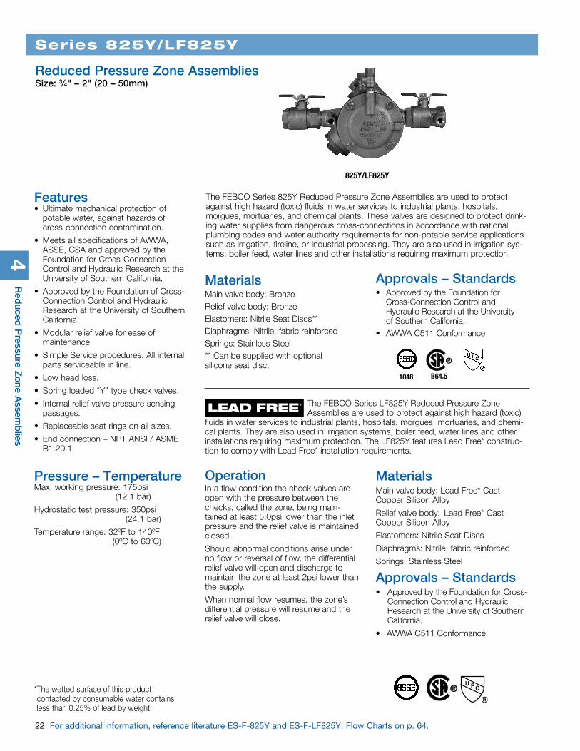
The FEBCO Series 825Y Reduced Pressure Zone Assemblies are used to protect against high hazard (toxic) fluids in water services to industrial plants, hospitals, morgues, mortuaries, and chemical plants. These valves are designed to protect drink-ing water supplies from dangerous cross-connections in accordance with national plumbing codes and water authority requirements for non-potable service applications such as irrigation, fireline, or industrial processing. They are also used in irrigation sys-tems, boiler feed, water lines and other installations requiring maximum protection.
Series 825Y/LF825Y
Reduced Pressure Zone AssembliesSize: 3⁄4" – 2" (20 – 50mm)
825Y/LF825Y
1048 B64.5
Features• Ultimate mechanical protection of
potable water, against hazards of cross-connection contamination.
• Meets all specifications of AWWA, ASSE, CSA and approved by the Foundation for Cross-Connection Control and Hydraulic Research at the University of Southern California.
• Approved by the Foundation of Cross-Connection Control and Hydraulic Research at the University of Southern California.
• Modular relief valve for ease of maintenance.
• Simple Service procedures. All internal parts serviceable in line.
• Low head loss.
• Spring loaded “Y” type check valves.
• Internal relief valve pressure sensing passages.
• Replaceable seat rings on all sizes.
• End connection – NPT ANSI / ASME B1.20.1
Pressure – Temperature Max. working pressure: 175psi (12.1 bar)
Hydrostatic test pressure: 350psi (24.1 bar)
Temperature range: 32ºF to 140ºF (0ºC to 60ºC)
MaterialsMain valve body: Bronze Relief valve body: Bronze Elastomers: Nitrile Seat Discs** Diaphragms: Nitrile, fabric reinforcedSprings: Stainless Steel** Can be supplied with optional silicone seat disc.
Approvals – Standards• Approved by the Foundation for
Cross-Connection Control and Hydraulic Research at the University of Southern California.
• AWWA C511 Conformance
The FEBCO Series LF825Y Reduced Pressure Zone Assemblies are used to protect against high hazard (toxic) fluids in water services to industrial plants, hospitals, morgues, mortuaries, and chemi-cal plants. They are also used in irrigation systems, boiler feed, water lines and other installations requiring maximum protection. The LF825Y features Lead Free* construc-tion to comply with Lead Free* installation requirements.
LEAD FREE*
OperationIn a flow condition the check valves are open with the pressure between the checks, called the zone, being main-tained at least 5.0psi lower than the inlet pressure and the relief valve is maintained closed.
Should abnormal conditions arise under no flow or reversal of flow, the differential relief valve will open and discharge to maintain the zone at least 2psi lower than the supply.
When normal flow resumes, the zone’s differential pressure will resume and the relief valve will close.
MaterialsMain valve body: Lead Free* Cast Copper Silicon Alloy
Relief valve body: Lead Free* Cast Copper Silicon Alloy
Elastomers: Nitrile Seat Discs
Diaphragms: Nitrile, fabric reinforced
Springs: Stainless Steel
Approvals – Standards• Approved by the Foundation for Cross-
Connection Control and Hydraulic Research at the University of Southern California.
• AWWA C511 Conformance
* The wetted surface of this product contacted by consumable water contains less than 0.25% of lead by weight.

Red
uced
Pre
ssur
e Z
one
Ass
emb
lies
4
23
Dimensions — Weights
Series 825Y/LF825Y
SIZE (DN) DIMENSIONS WEIGHT
A B* C D E in. mm in. mm In. mm in. mm in. mm in. mm lbs. kgs.
3⁄4 20 12 305 73⁄4 197 31⁄4 83 31⁄4 83 41⁄8 105 11.5 5.2 1 25 123⁄4 324 73⁄4 197 31⁄4 83 31⁄4 83 41⁄8 105 12.5 5.7 11⁄2 40 17 432 101⁄2 267 41⁄2 114 41⁄2 114 5 127 26.5 12.0 2 50 173⁄4 451 101⁄2 267 41⁄2 114 41⁄2 114 5 127 29.0 13.0
Top View
A
E
B
C
D
Dimensions are nominal.
NOTICEInquire with governing authorities for local installation requirements.
4R
educed
Pressure Z
one A
ssemb
lies
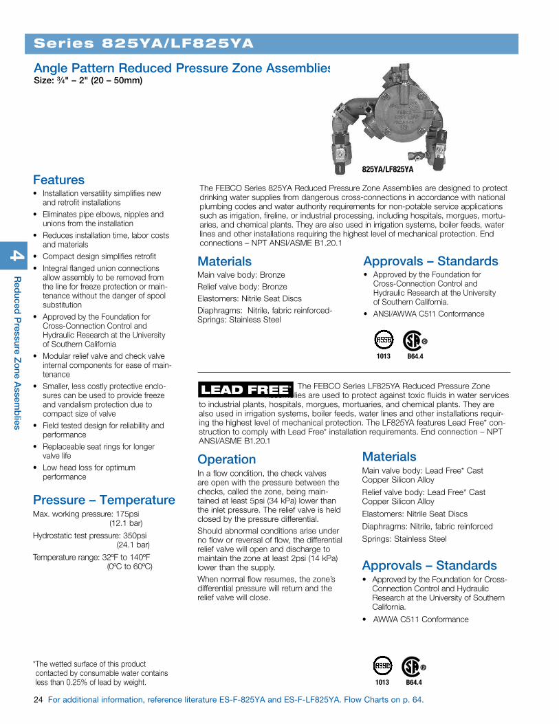
The FEBCO Series 825YA Reduced Pressure Zone Assemblies are designed to protect drinking water supplies from dangerous cross-connections in accordance with national plumbing codes and water authority requirements for non-potable service applications such as irrigation, fireline, or industrial processing, including hospitals, morgues, mortu-aries, and chemical plants. They are also used in irrigation systems, boiler feeds, water lines and other installations requiring the highest level of mechanical protection. End connections – NPT ANSI/ASME B1.20.1
Series 825YA/LF825YA
Angle Pattern Reduced Pressure Zone AssembliesSize: 3⁄4" – 2" (20 – 50mm)
825YA/LF825YAFeatures• Installation versatility simplifies new
and retrofit installations• Eliminates pipe elbows, nipples and
unions from the installation• Reduces installation time, labor costs
and materials• Compact design simplifies retrofit• Integral flanged union connections
allow assembly to be removed from the line for freeze protection or main-tenance without the danger of spool substitution
• Approved by the Foundation for Cross-Connection Control and Hydraulic Research at the University of Southern California
• Modular relief valve and check valve internal components for ease of main-tenance
• Smaller, less costly protective enclo-sures can be used to provide freeze and vandalism protection due to compact size of valve
• Field tested design for reliability and performance
• Replaceable seat rings for longer valve life
• Low head loss for optimum performance
Pressure – TemperatureMax. working pressure: 175psi (12.1 bar)
Hydrostatic test pressure: 350psi (24.1 bar)
Temperature range: 32ºF to 140ºF (0ºC to 60ºC)
1013 B64.4
MaterialsMain valve body: Bronze Relief valve body: Bronze Elastomers: Nitrile Seat DiscsDiaphragms: Nitrile, fabric reinforced-Springs: Stainless Steel
Approvals – Standards• Approved by the Foundation for
Cross-Connection Control and Hydraulic Research at the University of Southern California.
• ANSI/AWWA C511 Conformance
The FEBCO Series LF825YA Reduced Pressure Zone Assemblies are used to protect against toxic fluids in water services to industrial plants, hospitals, morgues, mortuaries, and chemical plants. They are also used in irrigation systems, boiler feeds, water lines and other installations requir-ing the highest level of mechanical protection. The LF825YA features Lead Free* con-struction to comply with Lead Free* installation requirements. End connection – NPT ANSI/ASME B1.20.1
LEAD FREE*
* The wetted surface of this product contacted by consumable water contains less than 0.25% of lead by weight.
OperationIn a flow condition, the check valves are open with the pressure between the checks, called the zone, being main-tained at least 5psi (34 kPa) lower than the inlet pressure. The relief valve is held closed by the pressure differential.Should abnormal conditions arise under no flow or reversal of flow, the differential relief valve will open and discharge to maintain the zone at least 2psi (14 kPa) lower than the supply.When normal flow resumes, the zone’s differential pressure will return and the relief valve will close.
MaterialsMain valve body: Lead Free* Cast Copper Silicon Alloy
Relief valve body: Lead Free* Cast Copper Silicon Alloy
Elastomers: Nitrile Seat Discs
Diaphragms: Nitrile, fabric reinforced
Springs: Stainless Steel
Approvals – Standards• Approved by the Foundation for Cross-
Connection Control and Hydraulic Research at the University of Southern California.
• AWWA C511 Conformance
1013 B64.4
24 For additional information, reference literature ES-F-825YA and ES-F-LF825YA. Flow Charts on p. 64.

SIZE (DN) DIMENSIONS WEIGHT
A B C D D1 E F G** in. mm in. mm in. mm in. mm in. mm in. mm in. mm in. mm in. mm lbs. kgs
3⁄4 20 125⁄8 321 117⁄8 302 41⁄2 114 35⁄8 92 n/a n/a 41⁄8 105 31⁄2 89 15⁄8 41 15.0 6.8 1 25 131⁄3 339 121⁄4 311 41⁄2 114 4 102 n/a n/a 41⁄8 105 37⁄8 98 15⁄8 41 16.5 7.5 11⁄2 40 18 457 165⁄8 422 6 152 51⁄4 133 n/a n/a 5 127 45⁄8 118 25⁄8 67 38.0 17.2 2 50 19 483 171⁄4 438 6 152 57⁄8 149 n/a n/a 5 127 51⁄4 133 25⁄8 67 41.0 18.6**G Dimension are based on standard vertical flow in / vertical flow out configuration.All dimensions are nominal.
Vertical Up Flow In - Horizontal Flow Out 825YA/LF825YA
Red
uced
Pre
ssur
e Z
one
Ass
emb
lies
4
25
Dimensions — Weights
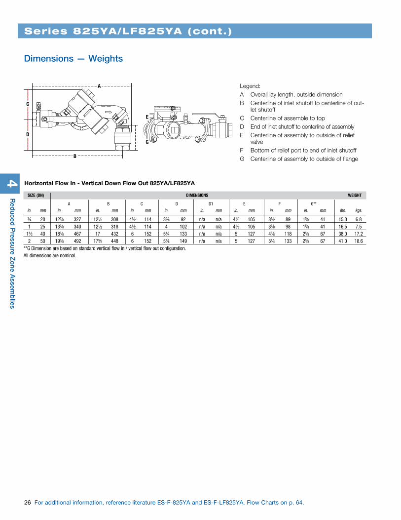
Vertical Up Flow In - Vertical Down Flow Out 825YA/LF825YA
SIZE (DN) DIMENSIONS WEIGHT
A B C D D1 E F G** in. mm in. mm in. mm in. mm in. mm in. mm in. mm in. mm in. mm lbs. kgs
3⁄4 20 10 254 81⁄2 216 31⁄4 83 47⁄8 124 45⁄8 118 41⁄8 105 31⁄2 89 15⁄8 41 15.0 6.8 1 25 101⁄4 260 81⁄2 216 31⁄4 83 51⁄4 133 5 127 41⁄8 105 37⁄8 98 15⁄8 41 16.5 7.5 11⁄2 40 141⁄4 362 111⁄2 292 41⁄2 114 67⁄8 175 61⁄2 165 5 127 45⁄8 118 25⁄8 67 38.0 17.2 2 50 147⁄8 378 111⁄2 292 41⁄2 114 71⁄2 191 71⁄2 181 5 127 51⁄4 133 25⁄8 67 41.0 18.6**G Dimension are based on standard vertical flow in / vertical flow out configuration.All dimensions are nominal.
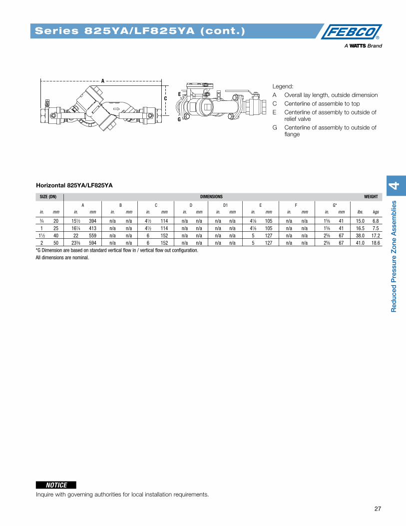
Legend:A Overall lay length, outside dimensionB Centerline of inlet shutoff to centerline of outlet
shutoffC Centerline of assemble to topD End of inlet shutoff to centerline of assemblyD1 Centerline of assembly to end of outlet shutoffE Centerline of assembly to outside of relief valveF Bottom of relief port to end of inlet shutoffG Centerline of assembly to outside of flange
Legend:A Overall lay length, outside dimensionB Centerline of inlet shutoff to centerline of
outlet shutoffC Centerline of assemble to topD End of inlet shutoff to centerline
of assemblyE Centerline of assembly to outside
of relief valveF Bottom of relief port to end of
inlet shutoffG Centerline of assembly to outside
of flange
E
GF
A
C
E
B
E
G
D1
A
C
DF
B
Series 825YA/LF825YA
NOTICEInquire with governing authorities for local installation requirements. • Continued on next page
SIZE (DN) DIMENSIONS WEIGHT
A B C D D1 E F G** in. mm in. mm in. mm in. mm in. mm in. mm in. mm in. mm in. mm lbs. kgs.
3⁄4 20 127⁄8 327 121⁄8 308 41⁄2 114 35⁄8 92 n/a n/a 41⁄8 105 31⁄2 89 15⁄8 41 15.0 6.8 1 25 133⁄8 340 121⁄2 318 41⁄2 114 4 102 n/a n/a 41⁄8 105 37⁄8 98 15⁄8 41 16.5 7.5 11⁄2 40 183⁄8 467 17 432 6 152 51⁄4 133 n/a n/a 5 127 45⁄8 118 25⁄8 67 38.0 17.2 2 50 193⁄8 492 175⁄8 448 6 152 57⁄8 149 n/a n/a 5 127 51⁄4 133 25⁄8 67 41.0 18.6**G Dimension are based on standard vertical flow in / vertical flow out configuration.All dimensions are nominal.
4R
educed
Pressure Z
one A
ssemb
lies
26 For additional information, reference literature ES-F-825YA and ES-F-LF825YA. Flow Charts on p. 64.
Dimensions — Weights
Series 825YA/LF825YA (cont.)
Horizontal Flow In - Vertical Down Flow Out 825YA/LF825YA
Legend:A Overall lay length, outside dimensionB Centerline of inlet shutoff to centerline of out-
let shutoffC Centerline of assemble to topD End of inlet shutoff to centerline of assemblyE Centerline of assembly to outside of relief
valveF Bottom of relief port to end of inlet shutoffG Centerline of assembly to outside of flange
A
C
D
B
E
G
Red
uced
Pre
ssur
e Z
one
Ass
emb
lies
4
27
SIZE (DN) DIMENSIONS WEIGHT
A B C D D1 E F G* in. mm in. mm in. mm in. mm in. mm in. mm in. mm in. mm in. mm lbs. kgs
3⁄4 20 151⁄2 394 n/a n/a 41⁄2 114 n/a n/a n/a n/a 41⁄8 105 n/a n/a 15⁄8 41 15.0 6.8 1 25 161⁄4 413 n/a n/a 41⁄2 114 n/a n/a n/a n/a 41⁄8 105 n/a n/a 15⁄8 41 16.5 7.5 11⁄2 40 22 559 n/a n/a 6 152 n/a n/a n/a n/a 5 127 n/a n/a 25⁄8 67 38.0 17.2 2 50 233⁄8 594 n/a n/a 6 152 n/a n/a n/a n/a 5 127 n/a n/a 25⁄8 67 41.0 18.6*G Dimension are based on standard vertical flow in / vertical flow out configuration.All dimensions are nominal.
Horizontal 825YA/LF825YA
Legend:A Overall lay length, outside dimensionC Centerline of assemble to topE Centerline of assembly to outside of
relief valveG Centerline of assembly to outside of
flange
CE
A
G
Series 825YA/LF825YA (cont.)
NOTICEInquire with governing authorities for local installation requirements.
4R
educed
Pressure Z
one A
ssemb
lies
28 For additional information, reference literature ES-F-860 and ES-F-LF860S. Flow Charts on p.65.
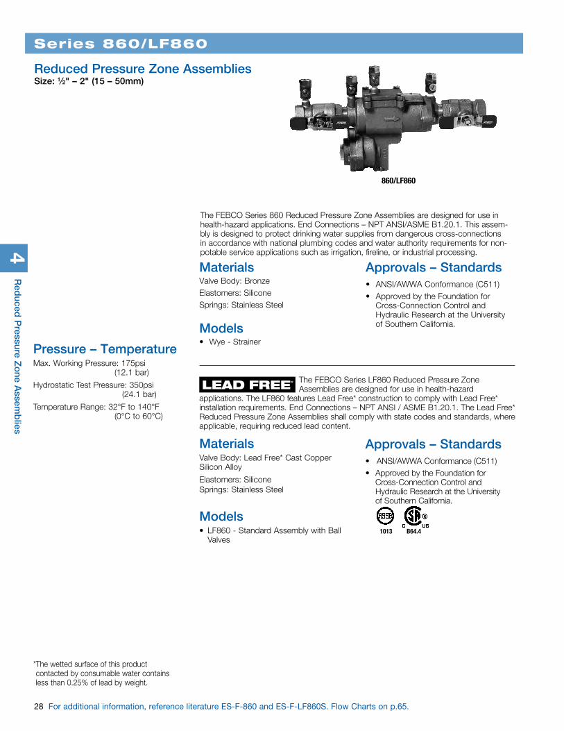
The FEBCO Series 860 Reduced Pressure Zone Assemblies are designed for use in health-hazard applications. End Connections – NPT ANSI/ASME B1.20.1. This assem-bly is designed to protect drinking water supplies from dangerous cross-connections in accordance with national plumbing codes and water authority requirements for non-potable service applications such as irrigation, fireline, or industrial processing.
Series 860/LF860
Reduced Pressure Zone AssembliesSize: 1⁄2" – 2" (15 – 50mm)
860/LF860
Pressure – TemperatureMax. Working Pressure: 175psi (12.1 bar)
Hydrostatic Test Pressure: 350psi (24.1 bar)
Temperature Range: 32°F to 140°F (0°C to 60°C)
1013 B64.4
MaterialsValve Body: BronzeElastomers: SiliconeSprings: Stainless Steel
Models• Wye - Strainer
Approvals – Standards• ANSI/AWWA Conformance (C511) • Approved by the Foundation for
Cross-Connection Control and Hydraulic Research at the University of Southern California.
The FEBCO Series LF860 Reduced Pressure Zone Assemblies are designed for use in health-hazard applications. The LF860 features Lead Free* construction to comply with Lead Free* installation requirements. End Connections – NPT ANSI / ASME B1.20.1. The Lead Free* Reduced Pressure Zone Assemblies shall comply with state codes and standards, where applicable, requiring reduced lead content.
MaterialsValve Body: Lead Free* Cast Copper Silicon Alloy
Elastomers: Silicone Springs: Stainless Steel
Models• LF860 - Standard Assembly with Ball
Valves
Approvals – Standards• ANSI/AWWA Conformance (C511) • Approved by the Foundation for
Cross-Connection Control and Hydraulic Research at the University of Southern California.
LEAD FREE*
* The wetted surface of this product contacted by consumable water contains less than 0.25% of lead by weight.
Red
uced
Pre
ssur
e Z
one
Ass
emb
lies
4
29
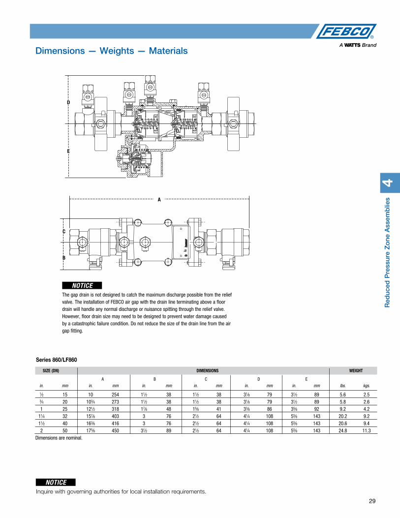
Dimensions — Weights — Materials
Series 860/LF860
SIZE (DN) DIMENSIONS WEIGHT
A B C D E in. mm in. mm in. mm in. mm in. mm in. mm lbs. kgs.
1⁄2 15 10 254 11⁄2 38 11⁄2 38 31⁄8 79 31⁄2 89 5.6 2.5 3⁄4 20 103⁄4 273 11⁄2 38 11⁄2 38 31⁄8 79 31⁄2 89 5.8 2.6 1 25 121⁄2 318 17⁄8 48 15⁄8 41 33⁄8 86 35⁄8 92 9.2 4.2 11⁄4 32 157⁄8 403 3 76 21⁄2 64 41⁄4 108 55⁄8 143 20.2 9.2 11⁄2 40 163⁄8 416 3 76 21⁄2 64 41⁄4 108 55⁄8 143 20.6 9.4 2 50 175⁄8 450 31⁄2 89 21⁄2 64 41⁄4 108 55⁄8 143 24.8 11.3Dimensions are nominal.
The gap drain is not designed to catch the maximum discharge possible from the relief valve. The installation of FEBCO air gap with the drain line terminating above a floor drain will handle any normal discharge or nuisance spitting through the relief valve. However, floor drain size may need to be designed to prevent water damage caused by a catastrophic failure condition. Do not reduce the size of the drain line from the air gap fitting.
C
B
A
D
E
NOTICEInquire with governing authorities for local installation requirements.
NOTICE
4R
educed
Pressure Z
one A
ssemb
lies
30 For additional information, reference literature ES-F-LF860L. Flow Charts on p. 65.
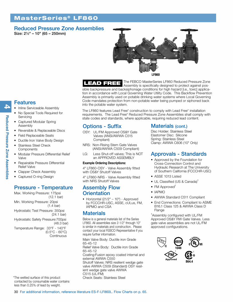
MasterSeries® LF860
Reduced Pressure Zone AssembliesSize: 21⁄2" – 10" (65 – 250mm)
LF860
LEAD FREE*
* The wetted surface of this product contacted by consumable water contains less than 0.25% of lead by weight.
The FEBCO MasterSeries LF860 Reduced Pressure Zone Assembly is specifically designed to protect against pos-sible backpressure and backsiphonage conditions for high hazard [i.e., toxic] applica-tion in accordance with Local Governing Water Utility Code. This Backflow Prevention Assembly is primarily used on potable drinking water systems where Local Governing Code mandates protection from non-potable water being pumped or siphoned back into the potable water system.
The LF860 features Lead Free* construction to comply with Lead Free* installation requirements. The Lead Free* Reduced Pressure Zone Assemblies shall comply with state codes and standards, where applicable, requiring reduced lead content.
Features• Inline Serviceable Assembly• No Special Tools Required for
Servicing• Captured Modular Spring Assembly• Reversible & Replaceable Discs• Field Replaceable Seats• Ductile Iron Valve Body Design• Stainless Steel Check Components• Modular Pressure Differential Relief
Valve• Repairable Pressure Differential
Relief Valve• Clapper Check Assembly• Captured O-ring Design
Pressure - TemperatureMax. Working Pressure: 175psi (12.1 bar)Min. Working Pressure: 20psi (1.4 bar)Hydrostatic Test Pressure: 350psi (24.1 bar)Hydrostatic Safety Pressure:700psi (48.3 bar)Temperature Range: 33°F - 140°F (0.5°C - 60°C) Continuous
Options - SuffixOSY: UL/FM Approved OS&Y Gate
Valves (ANSI/AWWA C515 Compliant)
NRS: Non-Rising Stem Gate Valves (ANSI/AWWA C509 Compliant)
LG: Less Shut-off valves; This is NOT an APPROVED ASSEMBLY
Example Ordering Descriptions:
4" LF860-OSY - Valve Assembly fitted with OS&Y Shutoff Valves
4" LF860-NRS - Valve Assembly fitted with NRS Shutoff Valves
Assembly Flow Orientation• Horizontal (21⁄2" – 10") - Approved
by FCCCHR-USC, ASSE, cULus, FM, IAPMO and CSA
MaterialsBelow is a general materials list of the Series LF860. All assemblies size 2-1/2" through 10" is similar in materials and construction. Please contact your local FEBCO Representative if you require further information.
Main Valve Body: Ductile iron Grade 65-45-12 Relief Valve Body: Ductile iron Grade 65-45-12 Coating:Fusion epoxy coated internal and external AWWA C550 Shutoff Valves: NRS resilient wedge gate valve AWWA C509 (Standard) OSY resil-ient wedge gate valve AWWA C515 (UL/FM) Check Seats: Stainless Steel
Disc Holder: Stainless Steel Elastomer Disc: Silicone Spring: Stainless Steel Clamp: AWWA C606 (10" Only)
Approvals - Standards• Approved by the Foundation for
Cross-Connection Control and Hydraulic Research at The University of Southern California (FCCCHR-USC)
• ASSE 1013 Listed
• UL Classified (US & Canada)†
• FM Approved†
• IAPMO
• AWWA Standard C511 Compliant
• End Connections: Compliant to ASME B16.1 Class 125 & AWWA Class D Flange
†Assembly configured with UL/FM Approved OS&Y RW Gate Valves. Less gate valve assemblies are not UL/FM approved configurations.
1048
B64.4
††
Materials (cont.)
Red
uced
Pre
ssur
e Z
one
Ass
emb
lies
4
31
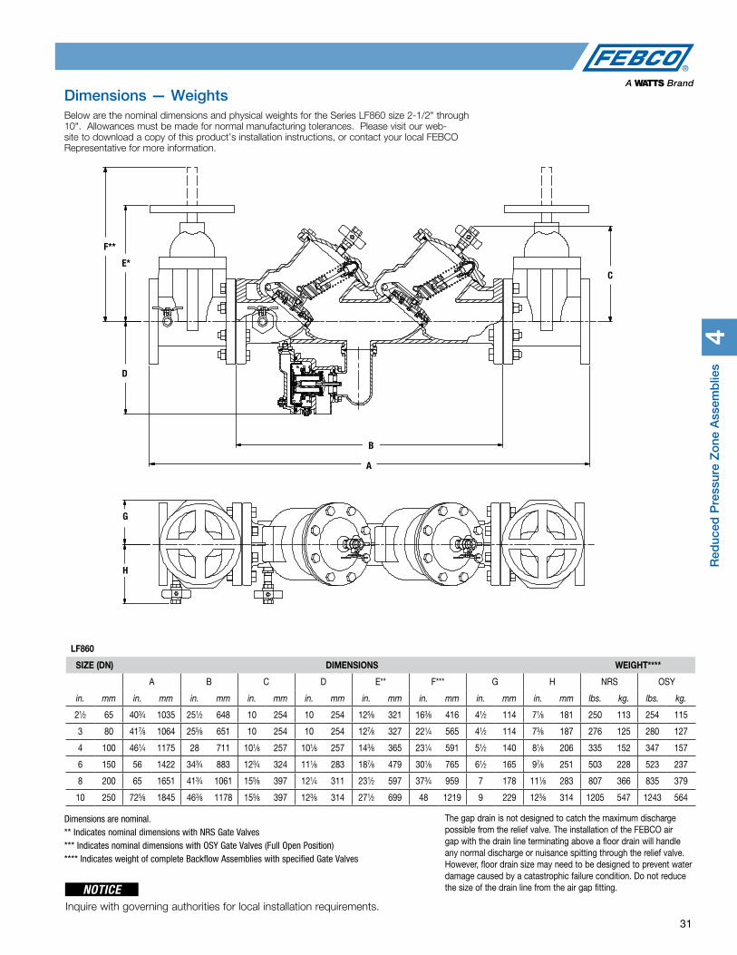
Dimensions — Weights Below are the nominal dimensions and physical weights for the Series LF860 size 2-1/2" through 10". Allowances must be made for normal manufacturing tolerances. Please visit our web-site to download a copy of this product’s installation instructions, or contact your local FEBCO Representative for more information.
LF860
SIZE (DN) DIMENSIONS WEIGHT****
A B C D E** F*** G H NRS OSY
in. mm in. mm in. mm in. mm in. mm in. mm in. mm in. mm in. mm lbs. kg. lbs. kg.
21⁄2 65 403⁄4 1035 251⁄2 648 10 254 10 254 125⁄8 321 163⁄8 416 41⁄2 114 71⁄8 181 250 113 254 115
3 80 417⁄8 1064 255⁄8 651 10 254 10 254 127⁄8 327 221⁄4 565 41⁄2 114 73⁄8 187 276 125 280 127
4 100 461⁄4 1175 28 711 101⁄8 257 101⁄8 257 143⁄8 365 231⁄4 591 51⁄2 140 81⁄8 206 335 152 347 157
6 150 56 1422 343⁄4 883 123⁄4 324 111⁄8 283 187⁄8 479 301⁄8 765 61⁄2 165 97⁄8 251 503 228 523 237
8 200 65 1651 413⁄4 1061 155⁄8 397 121⁄4 311 231⁄2 597 373⁄4 959 7 178 111⁄8 283 807 366 835 379
10 250 725⁄8 1845 463⁄8 1178 155⁄8 397 123⁄8 314 271⁄2 699 48 1219 9 229 123⁄8 314 1205 547 1243 564
Dimensions are nominal. ** Indicates nominal dimensions with NRS Gate Valves*** Indicates nominal dimensions with OSY Gate Valves (Full Open Position)**** Indicates weight of complete Backflow Assemblies with specified Gate Valves
The gap drain is not designed to catch the maximum discharge possible from the relief valve. The installation of the FEBCO air gap with the drain line terminating above a floor drain will handle any normal discharge or nuisance spitting through the relief valve. However, floor drain size may need to be designed to prevent water damage caused by a catastrophic failure condition. Do not reduce the size of the drain line from the air gap fitting.
A
B
E*C
D
F**
E*
F**
D
A
B
C
G
H
NOTICEInquire with governing authorities for local installation requirements.

4R
educed
Pressure Z
one A
ssemb
lies
32 For additional information, reference literature ES-F-860U and ES-F-LF860U. Flow Charts on p. 66.
Series 860U/LF860U
Reduced Pressure Zone Assemblies with Union End Ball ValvesSize: 1⁄2" – 2" (15 – 50mm)
860U/LF860U
Pressure – TemperatureMax. Working Pressure: 175psi (12.1 bar)Hydrostatic Test Press: 350psi (24.1 bar)Temperature Range: 32°F to 140°F (0°C to 60°C)
1013 B64.4
The FEBCO Series 860U Reduced Pressure Zone Assemblies are designed for and suitable for use in health hazard applications. Series 860U are designed to protect drinking water supplies from dangerous cross-connections in accordance with national plumbing codes and water authority requirements for non-potable service applications such as irrigation, fireline, or industrial processing. End Connections – NPT ANSI / ASME B1.20.1
Approvals – Standards• ANSI/AWWA Conformance (C511) • Approved by the Foundation for
Cross-Connection Control and Hydraulic Research at the University of Southern California.
LEAD FREE*
* The wetted surface of this product contacted by consumable water contains less than 0.25% of lead by weight.
MaterialsValve Body: Lead Free* Cast Copper Silicon Alloy Elastomers: Silicone Springs: Stainless Steel
1013 B64.4
The FEBCO Series LF860 Reduced Pressure Zone Assemblies are designed for use in health-hazard applications. The LF860S features Lead Free* construction to comply with Lead Free* installation requirements. End Connections – NPT ANSI / ASME B1.20.1. The Lead Free* Reduced Pressure Zone Assemblies shall comply with state codes and stan-dards, where applicable, requiring reduced lead content.
Approvals – Standards• ANSI/AWWA Conformance (C511) • Approved by the Foundation for Cross-
Connection Control and Hydraulic Research at the University of Southern California.

Red
uced
Pre
ssur
e Z
one
Ass
emb
lies
4
33
Dimensions — Weights
The gap drain is not designed to catch the maximum discharge possible from the relief valve. The installation of FEBCO air gap with the drain line terminating above a floor drain will handle any normal discharge or nuisance spitting through the relief valve. However, floor drain size may need to be designed to prevent water dam-age caused by a catastrophic failure condition. Do not reduce the size of the drain line from the air gap fitting.
NOTICESIZE (DN) DIMENSIONS WEIGHT
A B C D E
in. mm in. mm in. mm in. mm in. mm in. mm lbs. kgs.1⁄2 15 113⁄4 299 11⁄2 38 11⁄2 38 31⁄8 79 31⁄2 89 6.0 2.73⁄4 20 121⁄2 318 11⁄2 38 11⁄2 38 31⁄8 79 31⁄2 89 6.9 3.11 25 145⁄8 372 17⁄8 48 15⁄8 41 33⁄8 86 35⁄8 92 9.3 4.2
11⁄4 32 181⁄4 464 3 76 21⁄2 64 41⁄4 108 55⁄8 143 19.3 8.811⁄2 40 187⁄8 479 3 76 21⁄2 64 41⁄4 108 55⁄8 143 22.4 10.22 50 201⁄2 521 31⁄2 89 21⁄2 64 41⁄4 108 55⁄8 143 26.9 12.2
Series 860U/LF860U
D
E
C
A
B
Inquire with governing authorities for local installation requirements.
NOTICE
Dimensions are nominal.
4R
educed
Pressure Z
one A
ssemb
lies
34 For additional information, reference literature ES-F-880V amd ES-LF880V. Flow Charts on p. 67.
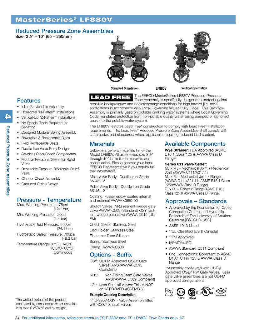
MasterSeries® LF880V
Reduced Pressure Zone AssembliesSize: 21⁄2" – 10" (65 – 250mm)
LF880VStandard Orientation Vertical Orientation
LEAD FREE*
Approvals – Standards• Approved by the Foundation for Cross-
Connection Control and Hydraulic Research at The University of Southern California [FCCCHR-USC]
• ASSE 1013 Listed
• **UL Classified [US & Canada]
• **FM Approved
• IAPMO/cUPC
• AWWA Standard C511 Compliant
• End Connections: Compliant to ASME B16.1 Class 125 & AWWA Class D Flange
**Assembly configured with UL/FM Approved OS&Y RW Gate Valves. Less gate valve assemblies are not UL/FM approved configurations.
MaterialsBelow is a general materials list of the Model LF880V. All assemblies size 21⁄2” through 10” is similar in materials and construction. Please contact your local FEBCO Representative if you require fur-ther information.
Main Valve Body: Ductile iron Grade 65-45-12
Relief Valve Body: Ductile iron Grade 65-45-12
Coating: Fusion epoxy coated internal and external AWWA C550-90
Shutoff Valves: NRS resilient wedge gate valve AWWA C509 (Standard) OSY resil-ient wedge gate valve AWWA C515 (UL/FM)
Check Seats: Stainless Steel
Disc Holder: Stainless Steel
Elastomer Disc: Silicone
Spring: Stainless Steel
Clamp: AWWA C606
Options - SuffixOSY: UL/FM Approved OS&Y Gate
Valves (ANSI/AWWA C515 Compliant)
NRS: Non-Rising Stem Gate Valves (ANSI/AWWA C509 Compliant)
LG : Less Shut-off valves; This is NOT an APPROVED ASSEMBLY
Example Ordering Description:
4” LF880V-OSY - Valve Assembly fitted with OS&Y Shutoff Valves
The FEBCO MasterSeries LF880V Reduced Pressure Zone Assembly is specifically designed to protect against possible backpressure and backsiphonage conditions for high hazard [i.e. toxic] applications in accordance with Local Governing Water Utility Code. This Backflow Assembly is primarily used on potable drinking water systems where Local Governing Code mandates protection from non-potable quality water being pumped or siphoned back into the potable water system.
The LF880V features Lead Free* construction to comply with Lead Free* installation requirements. The Lead Free* Reduced Pressure Zone Assemblies shall comply with state codes and standards, where applicable, requiring reduced lead content.
Features• Inline Serviceable Assembly• Horizontal “N-Pattern” Installations• Vertical-Up “Z-Pattern” Installations• No Special Tools Required for
Servicing• Captured Modular Spring Assembly• Reversible & Replaceable Discs• Field Replaceable Seats• Ductile Iron Valve Body Design• Stainless Steel Check Components• Modular Pressure Differential Relief
Valve• Repairable Pressure Differential Relief
Valve• Clapper Check Assembly• Captured O-ring Design
Pressure - TemperatureMax. Working Pressure: 175psi (12.1 bar)
Min. Working Pressure: 20psi (1.4 bar)
Hydrostatic Test Pressure: 350psi (24.1 bar)
Hydrostatic Safety Pressure: 700psi (48.3 bar)
Temperature Range: 33°F - 140°F (0.5°C- 60°C) Continuous
1013 B64.4
** **
Available ComponentsWye Strainer: FDA Approved (ASME B16.1 Class 125 & AWWA Class D Flange)
Series 611 Valve Setter: MJ x MJ - Mechanical Joint x Mechanical Joint (AWWA C111/A21.11) MJ x FL - Mechanical Joint x Flange (AWWA C111/A21.11; ASME B16.1 Class 125/AWWA Class D Flange) FL x FL – Flange x Flange (ASME B16.1 Class 125 & AWWA Class D Flange)
* The wetted surface of this product contacted by consumable water contains less than 0.25% of lead by weight.

Red
uced
Pre
ssur
e Z
one
Ass
emb
lies
4
35
Dimensions — Weights
SIZE (DN) DIMENSIONS WEIGHT
A B C D E NRS E1 OS&Y** F G H J K L M NRS OS&Y in. mm in. mm in. mm in. mm in. mm in. mm in. mm in. mm in. mm in. mm in. mm in. mm in. mm in. mm lbs. kgs. lbs. kgs.
21⁄2 65 121⁄2 318 253⁄4 654 241⁄4 616 415⁄16 125 125⁄8 321 163⁄8 416 165⁄8 422 61⁄4 159 51⁄2 140 31⁄2 89 135⁄8 346 71⁄4 184 271⁄4 692 210 95 220 99.8 3 80 121⁄2 318 253⁄4 654 243⁄4 629 57⁄16 138 127⁄8 327 221⁄4 565 165⁄8 422 61⁄4 159 51⁄2 140 33⁄4 95 141⁄8 359 71⁄4 184 281⁄4 718 280 127 290 131.5 4 100 14 356 277⁄8 708 263⁄4 680 69⁄16 167 143⁄8 365 231⁄4 591 173⁄4 451 7 178 6 152 41⁄2 114 151⁄2 394 71⁄4 184 31 787 320 145 350 158.8 6 150 16 406 321⁄4 819 321⁄4 819 89⁄16 218 187⁄8 497 301⁄8 765 219⁄16 548 8 203 71⁄2 191 51⁄2 140 185⁄8 473 91⁄2 241 371⁄4 946 480 218 530 240.4 8 200 181⁄2 470 371⁄2 953 363⁄8 924 99⁄16 243 231⁄2 597 373⁄4 959 247⁄8 632 91⁄4 235 83⁄4 222 63⁄4 172 203⁄4 527 101⁄4 260 411⁄2 1054 810 367 880 399.2 10 250 21 533 421⁄2 1080 403⁄4 1035 111⁄2 292 271⁄2 699 48 1219 271⁄2 699 10 254 93⁄4 248 8 203 24 610 111⁄2 292 48 1219 1350 612 480 671.3
Note: The Model LF880V is shipped in the standard (N-Shape) orientation.
NRS Side View
LF880V Standard Orientation LF880V Vertical Orientation
Relief Valve DetailRelief Valve shipped on right side (shown) field reversible to left side.
MasterSeries® LF880V
4 15⁄16
JE
E1
3 1⁄2
K
M
BG
D
C
FK
L
BA
GH
C
F
D
CL
**OS&Y OPEN
Weights do not include risers or optional valve setter.
Dimensions shown are nominal.
Refer to Specification Sheet ES-F-611 for details on valve setter.
Inquire with governing authorities for local installation requirements.
NOTICE

5R
educed
Pressure D
etector A
ssemb
lies
36 For additional information, reference literature ES-F-826YD. Flow Charts on p. 68.
Series 826YD
Reduced Pressure Detector AssembliesSize: 21⁄2" – 10" (65 – 250mm)
826YD
Installation The Reduced Pressure Detector Assembly should be installed horizontally with a suggested minimum clearance of 12" (300mm) between the assembly and the floor or grade. They must be installed where discharge from the relief valve will not be objectionable and can be positively drained away. They should be installed where easily accessible for testing and maintenance and must be protected from freezing. Thermal water expansion and/or water hammer down-stream of the backflow preventer can cause excessive pressure. Excessive pressure situations should be eliminated to avoid possible damage to the system and assembly.
OperationIn a nonflow condition, check valves on the by-pass and mainline units are closed with pressure between the checks, called the zone, being main-tained at least 5psi (35 kPa) lower than the inlet pressure and the relief valve is maintained closed. If the differential between the zone and the upstream pressure drops to 2psi (14kPa), the dif-ferential relief valve will open, maintaining proper zone differential. The by-pass reduced pressure backflow preventer will operate identically to the mainline assembly.The by-pass opens to detect initial flow and the mainline opens for all other flows.
The FEBCO Series 826YD Reduced Pressure Detector Assemblies designed to protect drinking water supplies from dangerous cross-connections in accordance with national plumbing codes and water authority requirements for non-potable service applications specifically for use with Automatic fire sprinkler systems containing toxic substances.
Features• The DuraCheck, features all stain-
less steel check assemblies for corrosion resistance, reduced foul-ing and longer valve life.
• DuraCast, ductile iron body for superior strength, corrosion resistance and lighter weight. By-pass line has water meter in series with an approved reduced pressure assembly.
• Low Head Loss• Approved by the Foundation for
Cross-Connnection Control and Hydraulic Research at the University of Southern California.
• End Detail is Flanged
1047
† †
Models• Less Gates
• Left hand by-pass
• Meter CFM/GPM
Approvals• Approved by the Foundation for Cross-
Connection Control and Hydraulic Research at the University of Southern California.†
† Valves must be supplied with resilient seated shutoff valves for USC and FM approvals to be in effect. UL and FM Listings only applicable with approved OS&Y gates.

Red
uced
Pre
ssur
e D
etec
tor
Ass
emb
lies
5
37
Dimensions — Weights
SIZE (DN) DIMENSIONS WEIGHT
A B C D E gates less gates
in. mm in. mm in. mm in. mm in. mm in. mm lbs. kgs. lbs. kgs.21⁄2 65 371⁄4 946 221⁄8 562 71⁄2 191 163⁄8 416 101⁄4 260 243 534.6 134 294.8
3 80 413⁄4 1061 255⁄8 651 81⁄2 216 221⁄4 565 101⁄2 267 298 655.6 154 338.8
4 100 507⁄16 1281 323⁄8 822 11 279 231⁄4 591 11 279 469 1031.8 194 426.8
6 150 593⁄4 1518 385⁄8 981 14 356 301⁄4 765 12 305 752 1654.4 397 873.4
8 200 693⁄16 1757 461⁄8 1172 18 457 373⁄4 959 13 330 1207 2655.4 537 1181.4
10 250 841⁄4 2140 581⁄8 1476 22 559 48 1219 14 356 1617 3557.4 957 2105.4
Dimensions shown are nominal.
Protective Enclosure
Support– 3" (80mm)
& larger
FEBCO MODEL 826YD
30" Max (750mm) 12" Min (300mm)
Suggested
Side View
Fire Hydrant
E
A
B
C
D
Series 826YD
Inquire with governing authorities for local installation requirements.
NOTICE
6V
acuum B
reakers
38 For additional information, reference literature ES-F-710_715. Flow Charts on p. 68.
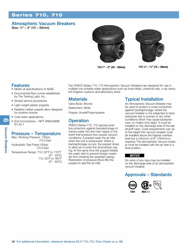
Series 710, 715
Atmospheric Vacuum BreakersSize: 1⁄2" – 2" (15 – 50mm)
710 1" – 2" (25 – 50mm) 715 1⁄2" – 3⁄4" (15 – 20mm)
The FEBCO Series 710, 715 Atmospheric Vacuum Breakers are designed for use in multiple non-potable water applications such as hose bibbs, chemical vats, x-ray tanks, turf irrigation systems and laboratory sinks.
Features• Meets all specifications of ASSE
• Documented flow curves established by The Twining Labs, Inc.
• Simple service procedures.
• Light weight plastic poppets.
• Resilient rubber poppet discs designed for positive closure.
• Cold water applications.
• End Connections – NPT ANSI/ASME B1.20.1
Pressure – TemperatureMax. Working Pressure: 150psi (10.3 bar)
Hydrostatic Test Press:150psi (10.3 bar)
Temperature Range: 710: 32°F to 110°F (0º - 43ºC) 715: 32°F to 180°F (0º - 82ºC)
1001 B64.1.1
MaterialsValve Body: BronzeElastomers: Nitrile
Poppet: Acetal/Polypropylene
OperationFEBCO Series 710, 715 assures posi-tive protection against backsiphonage of impure water into the main supply in the event that pressure loss causes vacuum conditions. A poppet seals the air inlet when the unit is pressurized. When a backsiphonage occurs, the poppet drops to allow air to enter the downstream pip-ing. At the same time the poppet shields the water inlet to prevent foreign materi-als from entering the upstream piping. Restoration of pressure (flow) lifts the poppet to seal the air inlet.
Typical InstallationAn Atmospheric Vacuum Breaker may be used to protect a cross-connection against backsiphonage, where the vacuum breaker is not subjected to back pressures due to pumps or any other conditions which may cause backpres-sure, no matter how slight. It must be installed on the discharge side of the last shutoff valve. Code requirements vary as to the height this vacuum breaker must be installed above the highest overflow level but a minimum of 6" (150mm) is required. The atmospheric vacuum break-er must be installed with the air inlet in a level position.
No valve of any type may be installed on the discharge side of an atmospheric vacuum breaker.
Approvals – Standards
NOTICE

Vac
uum
Bre
aker
s6
39
Dimensions — Weights
Series 710, 715
SIZE (DN) DIMENSIONS WEIGHT
A B C D
in. mm in. mm in. mm in. mm in. mm lbs. kgs.1⁄2 15 21⁄4 64 11⁄4 32 11⁄4 32 21⁄2 64 .75 .33⁄4 20 27⁄8 73 13⁄8 35 13⁄8 35 21⁄2 64 1 .51 25 31⁄2 89 13⁄8 35 11⁄2 38 31⁄4 83 1.75 .8
11⁄4 32 37⁄8 98 15⁄8 41 2 51 4 102 2.5 1.111⁄2 40 45⁄8 118 21⁄8 54 21⁄8 54 41⁄2 114 3.75 1.72 50 53⁄8 137 21⁄8 54 21⁄8 54 51⁄2 140 5.25 2.4
Weights shown are approximate. Dimensions shown are nominal.
A
D
B
C
Inquire with governing authorities for local installation requirements.
NOTICE
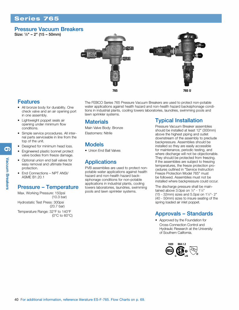
6V
acuum B
reakers
40 For additional information, reference literature ES-F-765. Flow Charts on p. 69.
The FEBCO Series 765 Pressure Vacuum Breakers are used to protect non-potable water applications against health hazard and non-health hazard backsiphonage condi-tions in industrial plants, cooling towers laboratories, laundries, swimming pools and lawn sprinkler systems.
Series 765
Pressure Vacuum BreakersSize: 1⁄2" – 2" (15 – 50mm)
765 765 U
1020 B64.1.2
MaterialsMain Valve Body: Bronze
Elastomers: Nitrile
Models• Union End Ball Valves
ApplicationsPVB assemblies are used to protect non-potable water applications against health hazard and non-health hazard back-siphonage conditions for non-potable applications in industrial plants, cooling towers laboratories, laundries, swimming pools and lawn sprinkler systems.
Features• All bronze body for durability. One
check valve and an air opening port in one assembly.
• Lightweight poppet seals air opening under minimum flow conditions.
• Simple service procedures. All inter-nal parts serviceable in line from the top of the unit.
• Designed for minimum head loss.• Engineered plastic bonnet protect
valve bodies from freeze damage.• Optional union end ball valves for
easy removal and ultimate freeze protection.
• End Connections – NPT ANSI/ASME B1.20.1
Pressure – TemperatureMax. Working Pressure: 150psi (10.3 bar)
Hydrostatic Test Press: 300psi (20.7 bar)
Temperature Range: 32°F to 140°F (0°C to 60°C)
Typical InstallationPressure Vacuum Breaker assemblies should be installed at least 12" (300mm) above the highest piping and outlet downstream of the assembly to preclude backpressure. Assemblies should be installed so they are easily accessible for maintenance, periodic testing, and where discharge will not be objectionable. They should be protected from freezing. If the assemblies are subject to freezing temperatures, the freeze protection pro-cedures outlined in "Service Instruction Freeze Protection Model 765" must be followed. Assemblies must not be installed where backpressure could occur.
The discharge pressure shall be main-tained above 3.0psi on 1⁄2" - 11⁄4" (15 - 32mm) sizes and 5.0psi on 11⁄2"- 2" (40 - 50mm) sizes to insure seating of the spring loaded air inlet poppet.
Approvals – Standards• Approved by the Foundation for
Cross-Connection Control and Hydraulic Research at the University of Southern California.
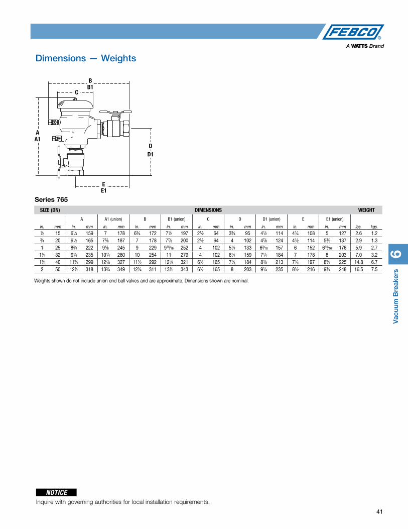
Vac
uum
Bre
aker
s6
41
Dimensions — Weights
BB1
C
AA1
DD1
EE1
Series 765
Inquire with governing authorities for local installation requirements.
NOTICE
SIZE (DN) DIMENSIONS WEIGHT
A A1 (union) B B1 (union) C D D1 (union) E E1 (union)
in. mm in. mm in. mm in. mm in. mm in. mm in. mm in. mm in. mm in. mm lbs. kgs.1⁄2 15 61⁄4 159 7 178 63⁄4 172 71⁄2 197 21⁄2 64 33⁄4 95 41⁄2 114 41⁄4 108 5 127 2.6 1.23⁄4 20 61⁄2 165 73⁄8 187 7 178 77⁄8 200 21⁄2 64 4 102 47⁄8 124 41⁄2 114 53⁄8 137 2.9 1.31 25 83⁄4 222 95⁄8 245 9 229 915⁄16 252 4 102 51⁄4 133 63⁄16 157 6 152 615⁄16 176 5.9 2.7
11⁄4 32 91⁄4 235 101⁄4 260 10 254 11 279 4 102 61⁄4 159 71⁄4 184 7 178 8 203 7.0 3.211⁄2 40 113⁄4 299 127⁄8 327 111⁄2 292 125⁄8 321 61⁄2 165 71⁄4 184 83⁄8 213 73⁄4 197 83⁄4 225 14.8 6.72 50 121⁄2 318 133⁄4 349 121⁄4 311 131⁄2 343 61⁄2 165 8 203 91⁄4 235 81⁄2 216 93⁄4 248 16.5 7.5
Weights shown do not include union end ball valves and are approximate. Dimensions shown are nominal.
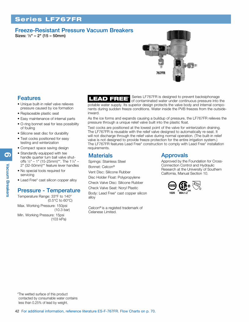
6V
acuum B
reakers
42 For additional information, reference literature ES-F-767FR. Flow Charts on p. 70.
Series LF767FR
Freeze-Resistant Pressure Vacuum BreakersSizes: 1⁄2" – 2" (15 – 50mm)
767FR
Features• Unique built-in relief valve relieves
pressure caused by ice formation• Replaceable plastic seat• Easy maintenance of internal parts• O-ring bonnet seal for less possibility
of fouling• Silicone seat disc for durability• Test cocks positioned for easy
testing and winterization• Compact space saving design• Standardly equipped with tee
handle quarter turn ball valve shut-offs 1⁄2" – 1" (15-25mm)**. The 11⁄4" – 2" (32-50mm)** feature lever handles
• No special tools required for servicing
• Lead Free* cast silicon copper alloy
Pressure - TemperatureTemperature Range: 33°F to 140° (0.5°C to 60°C)Max. Working Pressure: 150psi (10.3 bar)Min. Working Pressure: 15psi (103 kPa)
MaterialsSprings: Stainless SteelBonnet: Celcon®
Vent Disc: Silicone RubberDisc Holder Float: PolypropyleneCheck Valve Disc: Silicone RubberCheck Valve Seat: Noryl PlasticBody: Lead Free* cast copper silicon alloy
Celcon® is a registed trademark of Celanese Limited.
1020 B64.1.2
Series LF767FR is designed to prevent backsiphonage of contaminated water under continuous pressure into the potable water supply. Its superior design protects the valve body and internal compo-nents during sudden freeze conditions. Water inside the PVB freezes from the outside-inward. As the ice forms and expands causing a buildup of pressure, the LF767FR relieves the pressure through a unique relief valve built into the plastic float.Test cocks are positioned at the lowest point of the valve for winterization draining. The LF767FR is reusable with the relief valve designed to automatically re-seat. It will not discharge through the relief valve during normal operation. (The built-in relief valve is not designed to provide freeze protection for the entire irrigation system.) The LF767FR features Lead Free* construction to comply with Lead Free* installation requirements.
* The wetted surface of this product contacted by consumable water contains less than 0.25% of lead by weight.
ApprovalsApproved by the Foundation for Cross-Connection Control and Hydraulic Research at the University of Southern California, Manual Section 10.
LEAD FREE*
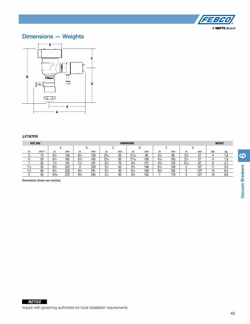
Vac
uum
Bre
aker
s6
43
Dimensions — Weights
LF767FR
D
C
E
A
G
B
SIZE (DN) DIMENSIONS WEIGHT
A B C D E Gin. mm** in. mm in. mm in. mm in. mm in. mm in. mm lbs. kg.1⁄2 15 61⁄8 156 61⁄4 159 29⁄16 65 311⁄16 94 37⁄8 98 21⁄4 57 4 1.83⁄4 20 61⁄2 165 61⁄2 165 29⁄16 65 315⁄16 100 41⁄8 105 21⁄4 57 4 1.81 25 71⁄2 191 71⁄2 191 23⁄4 70 43⁄4 121 47⁄8 124 37⁄16 87 6 2.7
11⁄4 32 87⁄8 225 9 229 31⁄4 83 53⁄4 146 61⁄8 156 5 127 11 5.011⁄2 40 91⁄4 235 91⁄2 241 31⁄4 83 61⁄4 159 63⁄8 162 5 127 14 6.32 50 105⁄8 270 95⁄8 245 31⁄4 83 63⁄8 162 7 178 5 127 19 8.6
Inquire with governing authorities for local installation requirements.
NOTICE
Dimensions shown are nominal.
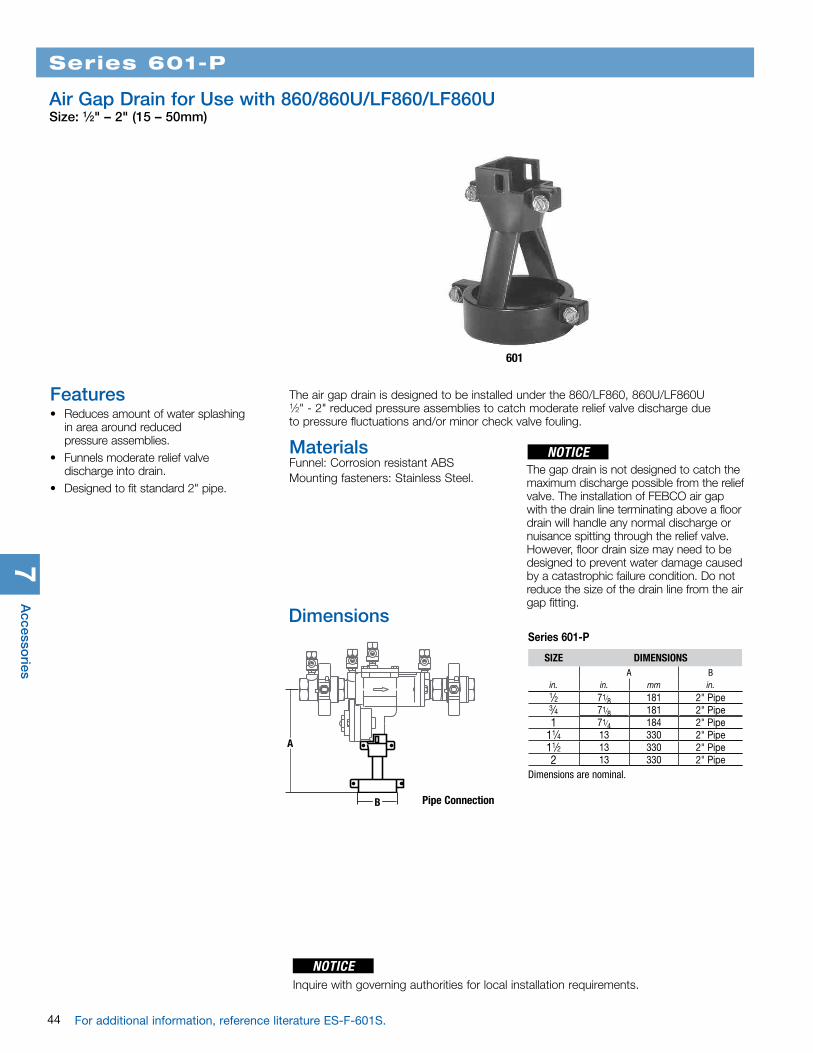
Series 601-P
Air Gap Drain for Use with 860/860U/LF860/LF860USize: 1⁄2" – 2" (15 – 50mm)
601
SIZE DIMENSIONSA B
in. in. mm in.1⁄2 71⁄8 181 2" Pipe3⁄4 71⁄8 181 2" Pipe1 71⁄4 184 2" Pipe
11⁄4 13 330 2" Pipe11⁄2 13 330 2" Pipe2 13 330 2" Pipe
Dimensions are nominal.
A
B Pipe Connection
Series 601-P
Dimensions
Features• Reduces amount of water splashing
in area around reduced pressure assemblies.
• Funnels moderate relief valve discharge into drain.
• Designed to fit standard 2" pipe.
The air gap drain is designed to be installed under the 860/LF860, 860U/LF860U 1⁄2" - 2" reduced pressure assemblies to catch moderate relief valve discharge due to pressure fluctuations and/or minor check valve fouling.
MaterialsFunnel: Corrosion resistant ABSMounting fasteners: Stainless Steel.
The gap drain is not designed to catch the maximum discharge possible from the relief valve. The installation of FEBCO air gap with the drain line terminating above a floor drain will handle any normal discharge or nuisance spitting through the relief valve. However, floor drain size may need to be designed to prevent water damage caused by a catastrophic failure condition. Do not reduce the size of the drain line from the air gap fitting.
NOTICE
44
7A
ccessories
Inquire with governing authorities for local installation requirements.
NOTICE
For additional information, reference literature ES-F-601S.
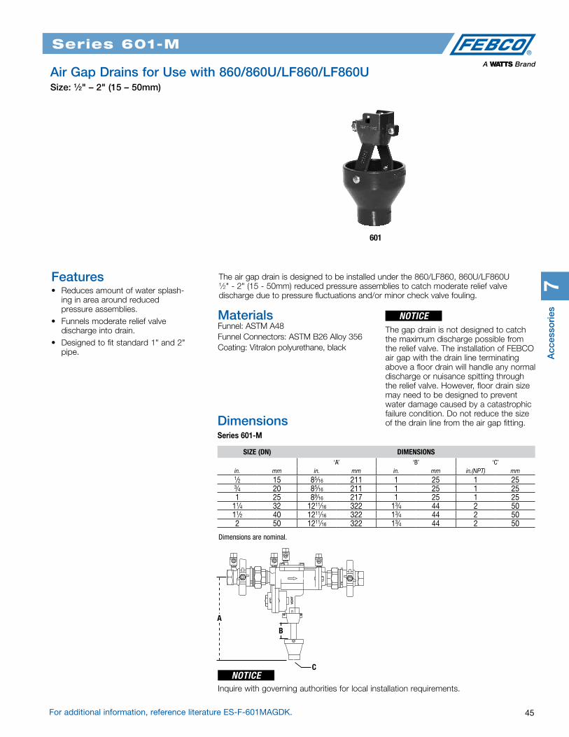
45
Series 601-M
Series 601-P
Air Gap Drains for Use with 860/860U/LF860/LF860U Size: 1⁄2" – 2" (15 – 50mm)
601
The air gap drain is designed to be installed under the 860/LF860, 860U/LF860U 1⁄2" - 2" (15 - 50mm) reduced pressure assemblies to catch moderate relief valve discharge due to pressure fluctuations and/or minor check valve fouling.
MaterialsFunnel: ASTM A48Funnel Connectors: ASTM B26 Alloy 356Coating: Vitralon polyurethane, black
The gap drain is not designed to catch the maximum discharge possible from the relief valve. The installation of FEBCO air gap with the drain line terminating above a floor drain will handle any normal discharge or nuisance spitting through the relief valve. However, floor drain size may need to be designed to prevent water damage caused by a catastrophic failure condition. Do not reduce the size of the drain line from the air gap fitting.
NOTICE
Features• Reduces amount of water splash-
ing in area around reduced pressure assemblies.
• Funnels moderate relief valve discharge into drain.
• Designed to fit standard 1" and 2" pipe.
Dimensions are nominal.
SIZE (DN) DIMENSIONS‘A’ ‘B’ ‘C’
in. mm in. mm in. mm in.(NPT) mm1⁄2 15 85⁄16 211 1 25 1 253⁄4 20 85⁄16 211 1 25 1 251 25 89⁄16 217 1 25 1 25
11⁄4 32 1211⁄16 322 13⁄4 44 2 5011⁄2 40 1211⁄16 322 13⁄4 44 2 502 50 1211⁄16 322 13⁄4 44 2 50
A
B
C
DimensionsSeries 601-M
Acc
esso
ries
7
Inquire with governing authorities for local installation requirements.
NOTICE
For additional information, reference literature ES-F-601MAGDK.

7A
ccessories
Series 601-M
The FEBCO Series 601 Air Gap Drains is constructed of coated aluminum. The air gap drain is designed to be attached to the relief valve of MasterSeries® reduced pressure assemblies, sizes 21⁄2" – 10" (65 – 250mm). Four inch drainage piping may be attached to drain, creating a system that catches and removes minor relief valve discharges due to pressure fluctuations and/or minor check valve fouling.
Note: The gap drain is not designed to catch the maximum discharge possible from the relief valve. The installation of FEBCO air gap with the drain line terminating above a floor drain will handle any normal discharge or nuisance spitting through the relief valve. However, floor drain size may need to be designed to prevent water damage caused by a catastrophic failure condition. Do not reduce the size of the drain line from the air gap fit-ting.
601
MaterialsNozzle: ASTM B26 Alloy 356Funnel: ASTM B26 Alloy 356Rods: ASTM B241 Alloy 6063Vitralon polyurethane coating black
Nozzle
Rods
Funnel
Front View Side View
A
H
D
B
C
G
B
E
Air Gap Drains for Use With MasterSeries® Reduced Pressure AssemblySizes: 21⁄2" – 10" (65 – 250mm)
Features• Nozzle design directs flow directly
into funnel, reducing side spray• Funnels minor relief valve discharges
into drains• Lightweight for easy installation• Coated for corrosion resistance• 4" funnel outlet is designed to
accept a hubless pipe coupling for simple drain pipe installation
46 For additional information, reference literature ES-F-601L.
Dimensions — Weights
Inquire with governing authorities for local installation requirements.
NOTICE
DIMENSIONS WEIGHTS
A B C D E F G H in. mm in. mm in. mm in. mm in. mm in. mm in. mm in. mm lbs. kgs.
131⁄8 333 63⁄8 162 53⁄8 137 31⁄2 89 313⁄16 97 27⁄32 56 43⁄8 111 97⁄8 251 2.2 1.0
601-M
Dimensions are nominal.

Acc
esso
ries
7
Series AGD
Air Gap Drains for Use With 825Y, LF825Y, 825YD and 826YD Reduced Pressure AssembliesAGD-Y: 3⁄4" – 2" (20 - 50mm) / AGD-L: 21⁄2" – 10" (65 - 250mm)
AGD
Features• Reduces amount of water splash-
ing in area around reduced pressure assemblies.
• Funnels minor relief valve discharge into drain.
• Conforms to air gap installation requirements.
A B (Air Gap)3⁄4" - 2"
Pipe Slip Fit21⁄2" - 10"
NPT ThreadC
SIZE DIMENSIONS WEIGHTSA B C
in. mm. in. mm in. mm. in. lbs. kgs.3⁄4 - 11⁄4 20 - 25 61⁄2 165 2 51 1" Pipe .12 .0511⁄2 - 2 40 - 50 71⁄2 191 23⁄4 70 1" Pipe .12 .05
21⁄2 65 121⁄4 311 53⁄4 146 2" NPT 7 3.23 80 121⁄2 318 53⁄4 146 2" NPT 7 3.24 100 123⁄4 324 53⁄4 146 2" NPT 7 3.26 150 13 330 53⁄4 146 2" NPT 7 3.28 200 131⁄2 343 53⁄4 146 2" NPT 7 3.210 250 133⁄4 349 53⁄4 146 2" NPT 7 3.2
Dimensions – Weights
AGD
The FEBCO Air Gap Drain is designed to be installed under the 825Y/LF825Y 3⁄4" - 2" and 825YD/826YD 21⁄2" - 10" reduced pressure assemblies to catch minor relief valve discharge due to pressure fluctuations and/or minor check valve fouling.
The gap drain is not designed to catch the maximum discharge possible from the relief valve. The installation of FEBCO air gap with the drain line terminating above a floor drain will handle any normal discharge or nuisance spitting through the relief valve. However, floor drain size may need to be designed to prevent water damage caused by a catastrophic failure condition. Do not reduce the size of the drain line from the air gap fitting.
NOTICEMaterialsFunnel: Corrosion resistant
Mounting Fasteners: Stainless Steel
47For additional information, reference literature ES-F-AGD.
Inquire with governing authorities for local installation requirements.
NOTICE
Dimensions are nominal.
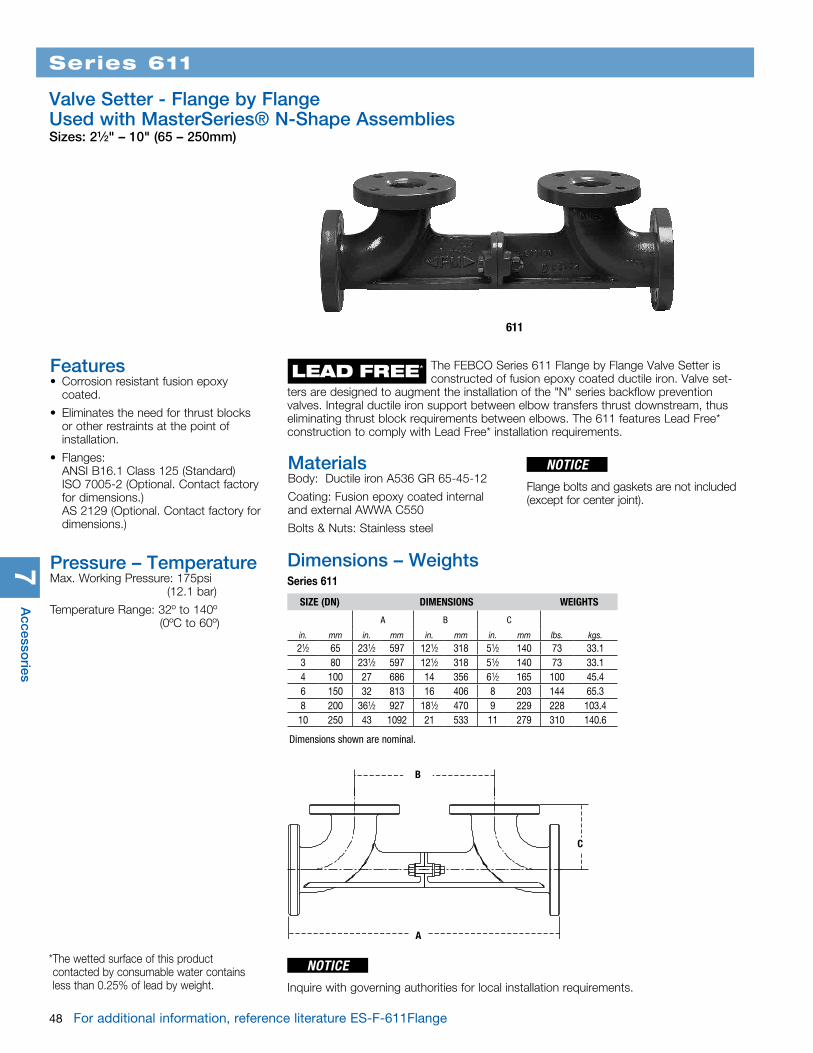
611
7A
ccessories
48 For additional information, reference literature ES-F-611Flange
Series 611
Valve Setter - Flange by Flange Used with MasterSeries® N-Shape AssembliesSizes: 21⁄2" – 10" (65 – 250mm)
SIZE (DN) DIMENSIONS WEIGHTS
A B C
in. mm in. mm in. mm in. mm lbs. kgs.21⁄2 65 231⁄2 597 121⁄2 318 51⁄2 140 73 33.13 80 231⁄2 597 121⁄2 318 51⁄2 140 73 33.14 100 27 686 14 356 61⁄2 165 100 45.46 150 32 813 16 406 8 203 144 65.38 200 361⁄2 927 181⁄2 470 9 229 228 103.410 250 43 1092 21 533 11 279 310 140.6
MaterialsBody: Ductile iron A536 GR 65-45-12
Coating: Fusion epoxy coated internal and external AWWA C550
Bolts & Nuts: Stainless steel
C
B
A
Dimensions – Weights Series 611
The FEBCO Series 611 Flange by Flange Valve Setter is constructed of fusion epoxy coated ductile iron. Valve set-ters are designed to augment the installation of the "N" series backflow prevention valves. Integral ductile iron support between elbow transfers thrust downstream, thus eliminating thrust block requirements between elbows. The 611 features Lead Free* construction to comply with Lead Free* installation requirements.
Features• Corrosion resistant fusion epoxy
coated.
• Eliminates the need for thrust blocks or other restraints at the point of installation.
• Flanges: ANSI B16.1 Class 125 (Standard) ISO 7005-2 (Optional. Contact factory for dimensions.) AS 2129 (Optional. Contact factory for dimensions.)
Pressure – TemperatureMax. Working Pressure: 175psi (12.1 bar)
Temperature Range: 32º to 140º (0ºC to 60º)
NOTICE
Flange bolts and gaskets are not included (except for center joint).
LEAD FREE*
Dimensions shown are nominal.
NOTICEInquire with governing authorities for local installation requirements.
* The wetted surface of this product contacted by consumable water contains less than 0.25% of lead by weight.
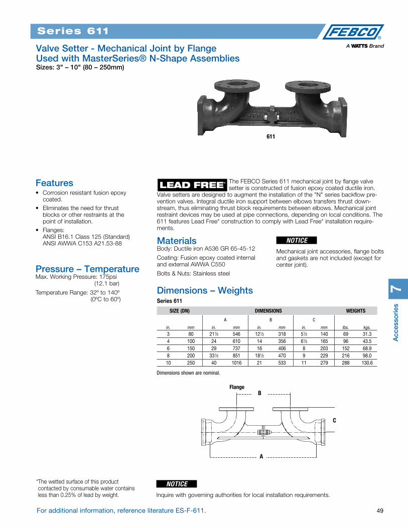
Acc
esso
ries
7
Series 611
Valve Setter - Mechanical Joint by Flange Used with MasterSeries® N-Shape AssembliesSizes: 3" – 10" (80 – 250mm)
For additional information, reference literature ES-F-611. 49
Series 611
611
LEAD FREE*
SIZE (DN) DIMENSIONS WEIGHTS
A B C
in. mm in. mm in. mm in. mm lbs. kgs.3 80 211⁄2 546 121⁄2 318 51⁄2 140 69 31.34 100 24 610 14 356 61⁄2 165 96 43.56 150 29 737 16 406 8 203 152 68.98 200 331⁄2 851 181⁄2 470 9 229 216 98.010 250 40 1016 21 533 11 279 288 130.6
MaterialsBody: Ductile iron A536 GR 65-45-12
Coating: Fusion epoxy coated internal and external AWWA C550
Bolts & Nuts: Stainless steel
C
B
A
Flange
Dimensions – Weights Series 611
The FEBCO Series 611 mechanical joint by flange valve setter is constructed of fusion epoxy coated ductile iron. Valve setters are designed to augment the installation of the "N" series backflow pre-vention valves. Integral ductile iron support between elbows transfers thrust down-stream, thus eliminating thrust block requirements between elbows. Mechanical joint restraint devices may be used at pipe connections, depending on local conditions. The 611 features Lead Free* construction to comply with Lead Free* installation require-ments.
Features• Corrosion resistant fusion epoxy
coated.• Eliminates the need for thrust
blocks or other restraints at the point of installation.
• Flanges: ANSI B16.1 Class 125 (Standard) ANSI AWWA C153 A21.53-88
Pressure – TemperatureMax. Working Pressure: 175psi (12.1 bar)
Temperature Range: 32º to 140º (0ºC to 60º)
* The wetted surface of this product contacted by consumable water contains less than 0.25% of lead by weight.
Dimensions shown are nominal.
NOTICEInquire with governing authorities for local installation requirements.
NOTICE
Mechanical joint accessories, flange bolts and gaskets are not included (except for center joint).
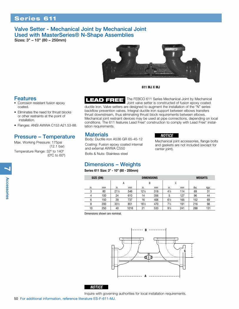
7A
ccessories
50 For additional information, reference literature ES-F-611-MJ.
Series 611
Valve Setter - Mechanical Joint by Mechanical Joint Used with MasterSeries® N-Shape AssembliesSizes: 3" – 10" (80 – 250mm)
611 MJ X MJ
MaterialsBody: Ductile iron A536 GR 65-45-12
Coating: Fusion epoxy coated internal and external AWWA C550
Bolts & Nuts: Stainless steel
B
A
C
Dimensions – Weights Series 611 Size: 3” - 10” (80 - 250mm)
SIZE (DN) DIMENSIONS WEIGHTS
A B C
in. mm in. mm in. mm in. mm lbs. kgs.3 80 211⁄2 546 121⁄2 318 41⁄2 114 69 314 100 24 610 14 356 5 127 96 446 150 29 737 16 406 61⁄2 165 152 698 200 331⁄2 851 181⁄2 470 71⁄2 191 216 9810 250 40 1016 21 533 91⁄2 241 288 131
Mechanical joint accessories, flange bolts and gaskets are not included (except for center joint).
LEAD FREE* The FEBCO 611 Series Mechanical Joint by Mechanical Joint valve setter is constructed of fusion epoxy coated ductile iron. Valve setters are designed to augment the installation of the “N” series backflow prevention valves. Integral ductile iron support between elbows transfers thrust downstream, thus eliminating thrust block requirements between elbows. Mechanical joint restraint devices may be used at pipe connections, depending on local conditions. The 611 features Lead Free* construction to comply with Lead Free* instal-lation requirements.
Features • Corrosion resistant fusion epoxy
coated.
• Eliminates the need for thrust blocks or other restraints at the point of installation.
• Flanges: ANSI AWWA C153 A21.53-88.
Pressure – TemperatureMax. Working Pressure: 175psi (12.1 bar)Temperature Range: 32º to 140º (0ºC to 60º)
Dimensions shown are nominal.
NOTICE
NOTICEInquire with governing authorities for local installation requirements.

Acc
esso
ries
7
For additional information, reference literature ES-F-PTC-1. Flow Charts on p. 70. 51
Series FPTC-1
Thermostatic Freeze Relief KitsSizes: 1⁄8" – 3⁄4" (3 – 20mm)
FPTC-1
IAPMO
1⁄8 – 1⁄4 models 1⁄2 – 3⁄4 models
Test Cock (optional)
25⁄16" (59mm)
13⁄16" (30mm) W/plug
31⁄4" (82mm)
21⁄4" (58mm)
5⁄8" (16mm)2" (51mm) UELC
Series FPTC-1 Thermostatic Freeze Relief Kits are designed to keep water from freezing in the backflow preventer, while avoiding discharges based on the air temperature drop-ping below freezing. Series FPTC-1 thermostatically measures the water temperature and opens at 35°F (1.6°C) and closes at 40°F (4.4°C).The series FPTC-1 are for use in accordance with national plumbing codes and water authority requirements for non-potable service applications such as irrigation and industrial processing.
Features• Compact• Easy to Install• Low Maintenance• Controlled by Water Temperature vs.
Air Temperature• IAPMO Approved
Pressure – TemperatureMax. Pressure: 175psi (12.1 bar)
Working Temperature: 35°F (1.6°C)
MaterialsBody: Bronze
Springs: Stainless Steel
Internals: DZR Brass
Approvals
Care should be given to ensure that dis-charged water will be adequately piped away from areas where slipping on ice could be a danger, such as roadways and pathways.
Dimensions
NOTICEInquire with governing authorities for local installation requirements.
NOTICE
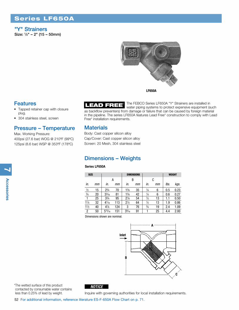
7A
ccessories
52 For additional information, reference literature ES-F-650A Flow Chart on p. 71.
The FEBCO Series LF650A “Y“ Strainers are installed in water piping systems to protect expensive equipment (such as backflow preventers) from damage or failure that can be caused by foreign material in the pipeline. The series LF650A features Lead Free* construction to comply with Lead Free* installation requirements.
LF650A
Series LF650A
"Y" StrainersSize: 1⁄2" – 2" (15 – 50mm)
Features• Tapped retainer cap with closure
plug. • 304 stainless steel, screen
Pressure – TemperatureMax. Working Pressure:400psi (27.6 bar) WOG @ 210ºF (99ºC)125psi (8.6 bar) WSP @ 353ºF (178ºC)
A
Inlet
C
B
Dimensions – Weights Series LF650A
SIZE DIMENSIONS WEIGHT
A B C in. mm in. mm in. mm in. mm lbs. kgs.
1⁄2 15 23⁄4 70 13⁄8 35 1⁄4 6 0.5 0.23 3⁄4 20 33⁄16 81 15⁄8 42 1⁄4 6 0.6 0.27 1 25 33⁄4 95 21⁄8 54 1⁄2 13 1.1 0.50 11⁄4 32 47⁄16 113 21⁄2 64 1⁄2 13 1.9 0.86 11⁄2 40 47⁄8 124 3 76 3⁄4 19 2.4 1.09 2 50 515⁄16 151 39⁄16 91 1 25 4.4 2.00
LEAD FREE*
MaterialsBody: Cast copper silicon alloyCap/Cover: Cast copper silicon alloyScreen: 20 Mesh, 304 stainless steel
NOTICEInquire with governing authorities for local installation requirements.
* The wetted surface of this product contacted by consumable water contains less than 0.25% of lead by weight.
Dimensions shown are nominal.

7
For additional information, reference literature ES-F-758A Flow Chart on p. 71. 53
Model 758A
"Y" StrainersSize: 21⁄2" – 10" (65 – 250mm)
758A
Dimensions – Weights Series 758A
A
B
SIZE (DN) DIMENSIONS WEIGHT
A B C
in. mm in. mm in. mm in. mm lbs. kgs.21⁄2 65 10 254 61⁄2 165 1 25 28 123 80 101⁄8 257 7 178 1 25 34 154 100 121⁄8 308 81⁄4 210 11⁄2 40 60 276 150 181⁄2 470 131⁄2 343 2 50 133 608 200 215⁄8 549 151⁄2 394 2 50 247 11210 250 26 660 181⁄2 470 2 50 370 168
The FEBCO Series 758A “Y“ strainers are installed in water piping systems to protect expensive equipment (such as backflow preventers) from damage or failure that can be caused by foreign mate-rial in the pipeline. Constructed of cast iron which complies with Lead Free* installation requirements.
Features• Unplugged, NPT blowoff connections
are situated on cover
• Recessed screen seats assure accu-rate screen alignment
• Screens are perforated 304 stainless steel
Pressure – TemperatureNon-Shock, 200psi @ 150º (13.8 bar @ 60ºC)
MaterialsBody: Cast Iron, ASTM A126-BCap/Cover: Carbon Steel, ASTM A36Gasket: Non-asbestosScreen: 21⁄2" - 4" (65 - 100mm) (1⁄16" Perf.) 6" - 10" (150 - 250mm) (1⁄8" Perf.)
* The wetted surface of this product contacted by consumable water contains less than 0.25% of lead by weight.
LEAD FREE*
C
NOTICEInquire with governing authorities for local installation requirements.
Dimensions shown are nominal.
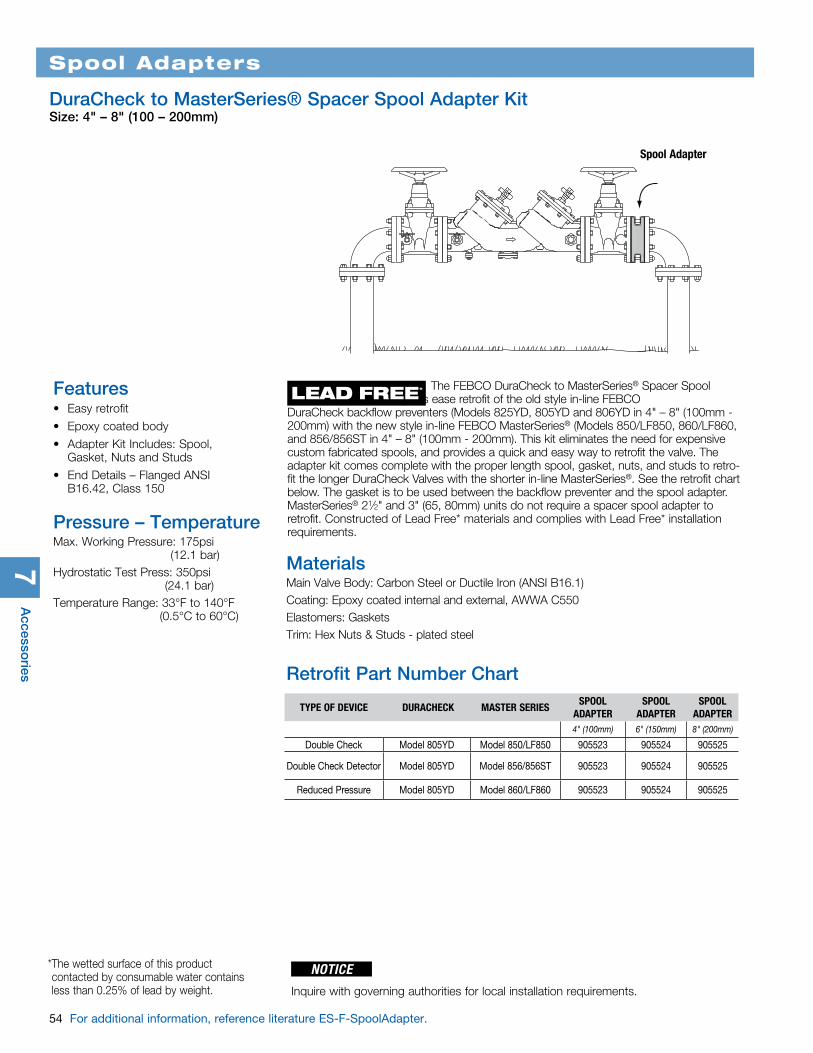
7A
ccessories
54 For additional information, reference literature ES-F-SpoolAdapter.
Spool Adapter
Spool Adapters
DuraCheck to MasterSeries® Spacer Spool Adapter KitSize: 4" – 8" (100 – 200mm)
MaterialsMain Valve Body: Carbon Steel or Ductile Iron (ANSI B16.1)Coating: Epoxy coated internal and external, AWWA C550Elastomers: GasketsTrim: Hex Nuts & Studs - plated steel
Retrofit Part Number Chart
The FEBCO DuraCheck to MasterSeries® Spacer Spool Adapters ease retrofit of the old style in-line FEBCO DuraCheck backflow preventers (Models 825YD, 805YD and 806YD in 4" – 8" (100mm - 200mm) with the new style in-line FEBCO MasterSeries® (Models 850/LF850, 860/LF860, and 856/856ST in 4" – 8" (100mm - 200mm). This kit eliminates the need for expensive custom fabricated spools, and provides a quick and easy way to retrofit the valve. The adapter kit comes complete with the proper length spool, gasket, nuts, and studs to retro-fit the longer DuraCheck Valves with the shorter in-line MasterSeries®. See the retrofit chart below. The gasket is to be used between the backflow preventer and the spool adapter. MasterSeries® 21⁄2" and 3" (65, 80mm) units do not require a spacer spool adapter to retrofit. Constructed of Lead Free* materials and complies with Lead Free* installation requirements.
LEAD FREE*Features• Easy retrofit
• Epoxy coated body
• Adapter Kit Includes: Spool, Gasket, Nuts and Studs
• End Details – Flanged ANSI B16.42, Class 150
Pressure – TemperatureMax. Working Pressure: 175psi (12.1 bar)Hydrostatic Test Press: 350psi (24.1 bar)Temperature Range: 33°F to 140°F (0.5°C to 60°C)
TYPE OF DEVICE DURACHECK MASTER SERIESSPOOL
ADAPTERSPOOL
ADAPTERSPOOL
ADAPTER4" (100mm) 6" (150mm) 8" (200mm)
Double Check Model 805YD Model 850/LF850 905523 905524 905525
Double Check Detector Model 805YD Model 856/856ST 905523 905524 905525
Reduced Pressure Model 805YD Model 860/LF860 905523 905524 905525
* The wetted surface of this product contacted by consumable water contains less than 0.25% of lead by weight.
NOTICEInquire with governing authorities for local installation requirements.

Acc
esso
ries
7
For additional information, reference literature ES-F-TC1. 55
Series LFTC1
Full Port Test CockSizes: 1⁄8" M x 1⁄4" F and 1⁄4" M x 1⁄4" F
Features• Lead Free* Cast Copper Silicon
Alloy• Full port design for low pressure
drop.• PTFE stem packing seal, thrust
washer and seat.• Quarter-turn open or close with slot
for coin or screw driver to operate.• Ideal for throttling and balancing
applications of non-abrasive fluids where flow is 20% to 100% of valve capacity.
• Low operating torque.Dimensions and Weights Series LFTC1
SIZE DIMENSIONS WEIGHT
A B F G
in. in. mm in. mm in. mm in. mm lbs. kgs.1⁄8M x 1⁄4F 1⁄8 x 1⁄4 3.0 x 6.4 13⁄4 45 11⁄16 17 11⁄16 17 .06 .031⁄4M x 1⁄4F 1⁄4 6.4 17⁄8 48 11⁄16 17 11⁄16 17 .06 .03
Dimensions shown are nominal.
LFTC1
B
A
F
G
LEAD FREE*
* The wetted surface of this product contacted by consumable water contains less than 0.25% of lead by weight.
The FEBCO Series LFTC1 is designed for the following applications:
• Test cock for backflow preventers
• Isolation valve for gauges
• Balancing Valve for gauges
• Lead Free* construction to comply with Lead Free* installation requirements
Inquire with governing authorities for local installation requirements.
NOTICE

7A
ccessories
56 For additional information, reference literature ES-F-TK-1
TK-1
Model TK-1
Backflow Preventer Test Kit
Features• Color-coded valves and hoses for
simplified operation• Top mounted drain/purge valves and
conveniently located line pressure gauge for ease of use
• A large 4.5" anti-parallax dial which indicates descending measurement, accurate to ± 1% of full scale
• Conveniently located needle valves for easy access
• Lightweight needle valves encased in a chemical-resistant body for trouble-free operation
• Replaceable hose filters and valve stem seals for field repair
• Complete kit contains gauge with color-coded valves and hoses, hose adapters, shock cord for easy mounting, supply pressure gauge. All contained in a durable carrying case with room for tools
The FEBCO Model TK-1 Backflow Preventer Test Kit has been designed for simplified operation and rugged reliability in a compact package. Offering the latest in gauge tech-nology, the FEBCO TK-1 provides dependable accuracy when testing pressure vacuum breakers, anti-spill vacuum breakers, reduced pressure backflow preventers or double check assemblies and is accurate to ±1% of full scale.
Pressure – TemperatureMax. Working Pressure: 200psi (13.8 bar)
Max. Working Temperature: 200°F (93°C)
Inquire with governing authorities for local installation requirements.
NOTICE

For additional information, reference literature ES-F-FPHB-1 Flow Chart on p. 70. 57
Series FPHB-1
Key Operated Wall HydrantsSizes: 3⁄4" – 1" (20 – 25mm)
FPHB-1
Series FPHB-1 Key Operated Wall Hydrants have been specifically designed to provide outside access to a building water supply for start-up, winterizing, and servicing of irri-gation sprinkler systems. The FPHB-1 is located outside of the home reducing the time spent on service calls. There is no need to locate the inside shutoff valve or the drain connection. Deploying the FPHB-1 wall hydrant enables the irrigation contractor to win-terize an irrigation system at anytime thereby protecting the contractors’ warranty and the homeowners’ investment. Non-potable applications.
When used in conjunction with the FEBCO Series 767 Pressure Vacuum Breaker or either a Series 825Y or 860 Reduced Pressure Zone Backflow Preventer, the installing contractor provides affordable freeze protection for both the irrigation system and the backflow preventer.
Features• Eliminates delays and multiple visits
to gain interior access to irrigation equipment
• Standardizes location of supply shutoff valve and drain connection
• Access available anytime for win-terizing
• Durable bronze valve body and shaft
• One piece valve plunger• Tamper resistant key operated
hydrant• Exterior chrome finish• Resilient seated shutoff• Union connection for ease of instal-
lation of backflow preventer
• Manual drain port
Pressure — TemperatureMaximum Working Pressure: 175psi (12.1 bar)
(10mm)3⁄8"
3⁄8" (10mm)
3⁄4" and 1" (20 and 25mm)
5" (127mm)
23⁄8" (61mm)
13⁄4" (44mm)
Dimensions Series FPHB-1
Materials• Chrome plated bronze valve head• Brass shaft with threaded end
MODELDISTANCE
(DN)PIPE
LENGTHSTEM
LENGTHin. mm in. mm in. mm
FPHB-1-8 8 200 9 229 125⁄16 313FPHB-1-10 10 250 11 279 145⁄16 364FPHB-1-12 12 300 13 330 165⁄16 389
Irri
gat
ion
Sp
ecia
lties
8Dimensions shown are nominal.
Inquire with governing authorities for local installation requirements.
NOTICE
Temperature Range: 33ºF - 140ºF (0.5ºC - 60ºC) continuous, 180ºF (82ºC) intermittent
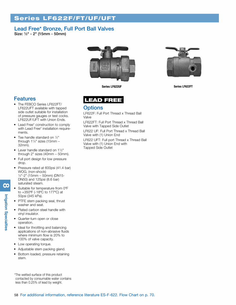
58 For additional information, reference literature ES-F-622. Flow Chart on p. 70.
Series LF622F/FT/UF/UFT
Lead Free* Bronze, Full Port Ball ValvesSize: 1⁄2" - 2" (15mm - 50mm)
Features• The FEBCO Series LF622FT/
LF622UFT available with tapped side outlet suitable for installation of pressure gauges or test cocks. LF622UF/UFT with Union Ends.
• Lead Free* construction to comply with Lead Free* installation require-ments.
• Tee handle standard on 1⁄2" through 11⁄4" sizes (15mm – 32mm).
• Lever handle standard on 11⁄2" through 2" sizes (40mm – 50mm).
• Full port design for low pressure drop.
• Pressure rated at 600psi (41.4 bar) WOG, (non-shock) 1⁄2"-2" (15mm – 50mm) (DN15-DN50) and 125psi (8.6 bar) saturated steam.
• Suitable for temperature from 0ºF to +350ºF (-18ºC to 177ºC) at 50psi (345 kPa).
• PTFE stem packing seal, thrust washer and seat.
• Plated carbon steel handle with vinyl insulator.
• Quarter-turn open or close operation.
• Ideal for throttling and balancing applications of non-abrasive fluids where minimum flow is 20% to 100% of valve capacity.
• Low operating torque.• Adjustable stem packing gland.• Bottom loaded, pressure retaining
stem.
Series LF622UF Series LF622FT
OptionsLF622F: Full Port Thread x Thread Ball ValveLF622FT: Full Port Thread x Thread Ball Valve with Tapped Side OutletLF622 UF: Full Port Thread x Thread Ball Valve with (1) Union EndLF622 UFT: Full port Thread x Thread Ball Valve with (1) Union End with Tapped Side Outlet
* The wetted surface of this product contacted by consumable water contains less than 0.25% of lead by weight.
LEAD FREE*
8Irrig
ation S
pecialties
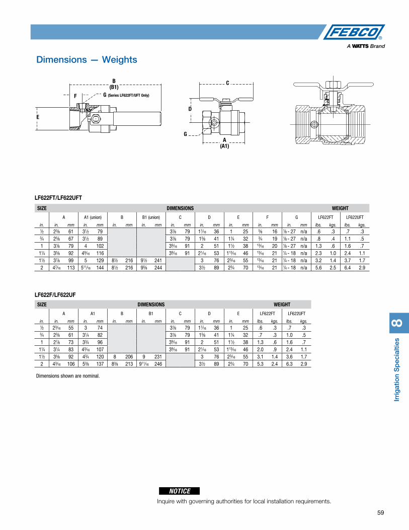
Irri
gat
ion
Sp
ecia
lties
8
59
Dimensions — Weights
SIZE DIMENSIONS WEIGHT
A A1 (union) B B1 (union) C D E F G LF622FT LF622UFT
in. in. mm in. mm in. mm in. mm in. mm in. mm in. mm in. mm in. mm lbs. kgs. lbs. kgs.1⁄2 23⁄8 61 31⁄2 79 31⁄8 79 17⁄16 36 1 25 5⁄8 16 1⁄8 - 27 n/a .6 .3 .7 .33⁄4 25⁄8 67 31⁄2 89 31⁄8 79 15⁄8 41 11⁄4 32 3⁄4 19 1⁄8 - 27 n/a .8 .4 1.1 .51 31⁄8 79 4 102 39⁄16 91 2 51 11⁄2 38 13⁄16 20 1⁄8 - 27 n/a 1.3 .6 1.6 .7
11⁄4 35⁄8 92 49⁄16 116 39⁄16 91 21⁄16 53 113⁄16 46 13⁄16 21 1⁄4 - 18 n/a 2.3 1.0 2.4 1.111⁄2 37⁄8 99 5 129 81⁄2 216 91⁄2 241 3 76 23⁄16 55 13⁄16 21 1⁄4 - 18 n/a 3.2 1.4 3.7 1.72 47⁄16 113 511⁄16 144 81⁄2 216 95⁄8 244 31⁄2 89 23⁄4 70 13⁄16 21 1⁄4 - 18 n/a 5.6 2.5 6.4 2.9
SIZE DIMENSIONS WEIGHT
A A1 B B1 C D E LF622FT LF622UFT
in. in. mm in. mm in. mm in. mm in. mm in. mm in. mm lbs. kgs. lbs. kgs.1⁄2 23⁄16 55 3 74 31⁄8 79 17⁄16 36 1 25 .6 .3 .7 .33⁄4 23⁄8 61 31⁄4 82 31⁄8 79 15⁄8 41 11⁄4 32 .7 .3 1.0 .51 27⁄8 73 33⁄4 96 39⁄16 91 2 51 11⁄2 38 1.3 .6 1.6 .7
11⁄4 31⁄4 83 43⁄16 107 39⁄16 91 21⁄16 53 113⁄16 46 2.0 .9 2.4 1.111⁄2 35⁄8 92 43⁄4 120 8 206 9 231 3 76 23⁄16 55 3.1 1.4 3.6 1.72 43⁄16 106 53⁄8 137 83⁄8 213 911⁄16 246 31⁄2 89 23⁄4 70 5.3 2.4 6.3 2.9
LF622FT/LF622UFT
LF622F/LF622UF
E
F
B (B1)
G (Series LF622FT/UFT Only)
D
C
A (A1)
G
Inquire with governing authorities for local installation requirements.
NOTICE
Dimensions shown are nominal.

Series 850S/LF850S
kPa psi
138 20
103 15
69 10
34 5
0
0
2" (50mm)
0 30 60 90 120 150 180 gpm 0 114 227 341 454 570 681 lpm
Hea
dlo
ss (p
si)
kPa psi
138 20
103 15
69 10
34 5
0
0
11⁄2" (40mm)
0 20 40 60 80 100 120 gpm 0 76 152 227 303 379 454 lpm
Hea
dlo
ss (p
si)
kPa psi
138 20
103 15
69 10
34 5
0
0
11⁄4" (32mm)
0 20 40 60 80 100 120 gpm 0 76 152 227 303 379 454 lpm
Hea
dlo
ss
(psi
)
kPa psi
138 20
103 15
69 10
34 5
0
0
1" (25mm)
0 10 20 30 40 50 60 gpm 0 38 76 114 152 190 227 lpm
Hea
dlo
ss (p
si)
kPa psi
138 20
103 15
69 10
34 5
0 0
3⁄4" (20mm)
0 5 10 15 20 25 30 gpm 0 19 38 57 76 95 114 lpm
Hea
dlo
ss (p
si)
kPa psi
138 20
103 15
69 10
34 5
0 0
1⁄2" (15mm)
0 3 6 9 12 15 18 gpm 0 11 23 34 45 57 68 lp
Hea
dlo
ss (p
si)
60
Flow Charts
Series 800
kPa psi
69 10
34 5
0 0
4" (100mm) kPa psi
69 10
34 5
0 0
Hea
dlo
ss
6" (150mm)
Hea
dlo
ssH
ead
loss
8" (200mm)
kPa psi
69 10
34 5
0 0 1000 1500 2000 2500 3000 3500 4000 4500 gpm 3800 5700 7600 9460 11400 13250 15140 17030 lpm 15 fps 4.6 mps
Hea
dlo
ss
10" (250mm)
kPa psi
69 10
34 5
0 0
kPa psi 103 15
69 10
34 5
0 0
Velocities are calculated for flows in Schedule 40 steel pipe.
Head
Los
s
0 50 100 150 200 250 300 gpm 0 190 379 570 760 950 1140 lpm
Series 406
9F
low
Charts
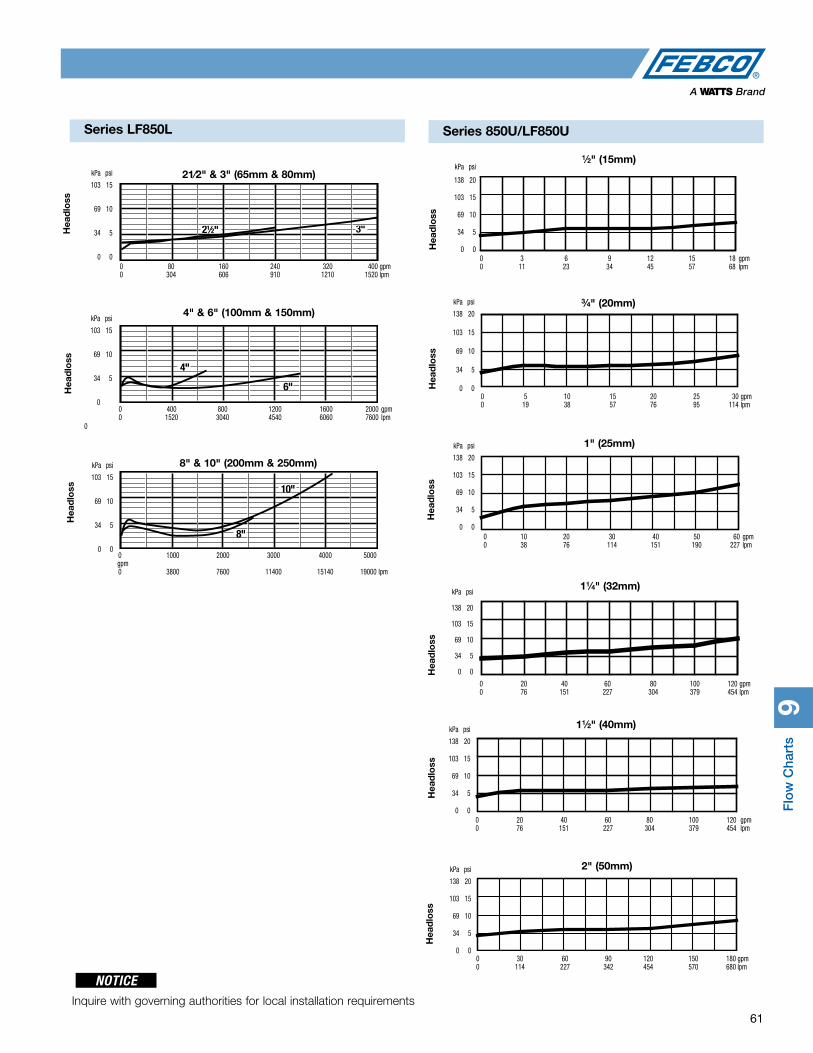
Flo
w C
hart
s9
61
Series LF850L
Hea
dlo
ss
21⁄2" 3"
21⁄2" & 3" (65mm & 80mm) kPa psi
103 15
69 10
34 5
0 0 0 80 160 240 320 400 gpm 0 304 606 910 1210 1520 lpm
4" & 6" (100mm & 150mm) kPa psi
103 15
69 10
34 5
0
0
0 400 800 1200 1600 2000 gpm 0 1520 3040 4540 6060 7600 lpm
8" & 10" (200mm & 250mm) kPa psi
103 15
69 10
34 5
0 0 0 1000 2000 3000 4000 5000 gpm 0 3800 7600 11400 15140 19000 lpm
Hea
dlo
ssH
ead
loss
1⁄2" (15mm) kPa psi
138 20
103 15
69 10
34 5
0 0 0 3 6 9 12 15 18 gpm 0 11 23 34 45 57 68 lpm
Hea
dlo
ss
3⁄4" (20mm) kPa psi
138 20
103 15
69 10
34 5
0 0 0 5 10 15 20 25 30 gpm 0 19 38 57 76 95 114 lpm
Hea
dlo
ss1" (25mm) kPa psi
138 20
103 15
69 10
34 5
0 0 0 10 20 30 40 50 60 gpm 0 38 76 114 151 190 227 lpm
Hea
dlo
ss
11⁄4" (32mm) kPa psi
138 20
103 15
69 10
34 5
0 0
0 20 40 60 80 100 120 gpm 0 76 151 227 304 379 454 lpm
Hea
dlo
ss
11⁄2" (40mm) kPa psi
138 20
103 15
69 10
34 5
0 0 0 20 40 60 80 100 120 gpm 0 76 151 227 304 379 454 lpm
Hea
dlo
ss
2" (50mm) kPa psi
138 20
103 15
69 10
34 5
0 0 0 30 60 90 120 150 180 gpm 0 114 227 342 454 570 680 lpm
Hea
dlo
ss
Series 850U/LF850U
Inquire with governing authorities for local installation requirements
NOTICE
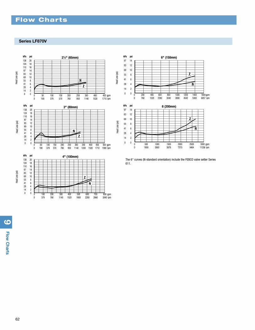
9F
low
Charts
Series LF870V
62
Flow Charts
21⁄2" (65mm) kPa psi
138 20 124 18 110 16 97 14 83 12 69 10 55 8 41 6 28 4 14 2 0 0
kPa psi
97 14
83 12
69 10
55 8
41 6
28 4
14 2
0 0
Head
Los
s (ps
i)
Head
Los
s (ps
i)
0 50 100 150 200 250 300 400 450 gpm 0 190 379 570 760 950 1140 1520 1710 lpm
kPa psi
138 20 124 18 110 16 97 14 83 12 69 10 55 8 41 6 28 4 14 2 0 0
Head
Los
s (ps
i)
Head
Los
s (ps
i)
kPa psi
138 20 124 18 110 16 97 14 83 12 69 10 55 8 41 6 28 4 14 2 0 0
Head
Los
s (ps
i)
6" (150mm)
3" (80mm) 8 (200mm)
4" (100mm)
kPa psi
97 14
83 12
69 10
55 8
41 6
28 4
14 2
0 0 0 50 100 150 200 250 300 350 400 450 500 gpm 0 190 379 570 760 950 1140 1330 1520 1710 1900 lpm
0 200 400 600 800 1000 1200 1400 1600 gpm 0 760 1520 2280 3040 3800 4542 5300 6057 lpm
0 500 1000 1500 2000 2500 3000 gpm 0 1900 3800 5678 7570 9464 11356 lpm
NN
N
N
N
Z
Z
Z
Z
Z
0 100 200 300 400 500 600 700 800 gpm 0 379 760 1140 1520 1900 2280 2660 3040 lpm
The 6" curves (N-standard orientation) include the FEBCO valve setter Series 611.
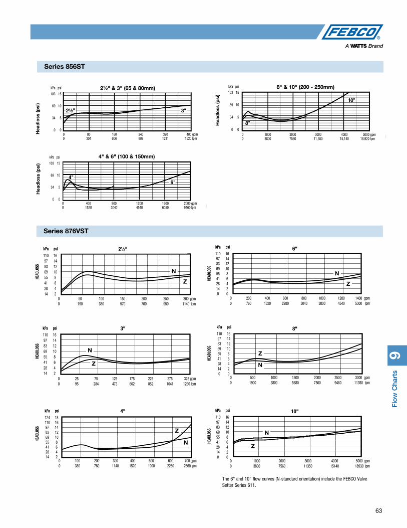
Flo
w C
hart
s9
63
21⁄2" & 3" (65 & 80mm) kPa psi
103 15
69 10
34 5
0 0 0 80 160 240 320 400 gpm 0 304 606 909 1211 1520 lpm
kPa psi
103 15
69 10
34 5
0 0 0 400 800 1200 1600 2000 gpm 0 1520 3040 4540 6050 9460 lpm
4" & 6" (100 & 150mm)
Hea
dlo
ss (p
si)
Hea
dlo
ss (p
si)
kPa psi
103 15
69 10
34 5
0 0 0 1000 2000 3000 4000 5000 gpm 0 3800 7560 11,350 15,140 18,920 lpm
8" & 10" (200 - 250mm)
Hea
dlo
ss (p
si)
Series 856ST
Series 876VST
N
ZN
Z
N
Z N
Z
N
ZN
Z
N
ZN
Z
N
Z N
Z
N
ZN
Z
The 6" and 10" flow curves (N-standard orientation) include the FEBCO Valve Setter Series 611.
21⁄2" kPa psi
110 16 97 14 83 12 69 10 55 8 41 6 28 4 14 2
0 50 100 150 200 250 300 gpm 0 190 380 570 760 950 1140 lpm
HEAD
LOSS
3" kPa psi
110 16 97 14 83 12 69 10 55 8 41 6 28 4 14 2
0 25 75 125 175 225 275 325 gpm 0 95 284 473 662 852 1041 1230 lpm
HEAD
LOSS
4" kPa psi
124 18 110 16 97 14 83 12 69 10 55 8 41 6 28 4 14 2
0 100 200 300 400 500 600 700 gpm 0 380 760 1140 1520 1900 2280 2660 lpm
HEAD
LOSS
6" kPa psi
110 16 97 14 83 12 69 10 55 8 41 6 28 4 14 2 0 0
0 200 400 600 800 1000 1200 1400 gpm 0 760 1520 2280 3040 3800 4540 5300 lpm
HEAD
LOSS
8" kPa psi
110 16 97 14 83 12 69 10 55 8 41 6 28 4 14 2 0 0
0 500 1000 1500 2000 2500 3000 gpm 0 1900 3800 5680 7560 9460 11350 lpm
HEAD
LOSS
10" kPa psi
110 16 97 14 83 12 69 10 55 8 41 6 28 4 14 2 0 0
0 1000 2000 3000 4000 5000 gpm 0 3800 7560 11350 15140 18930 lpm
HEAD
LOSS
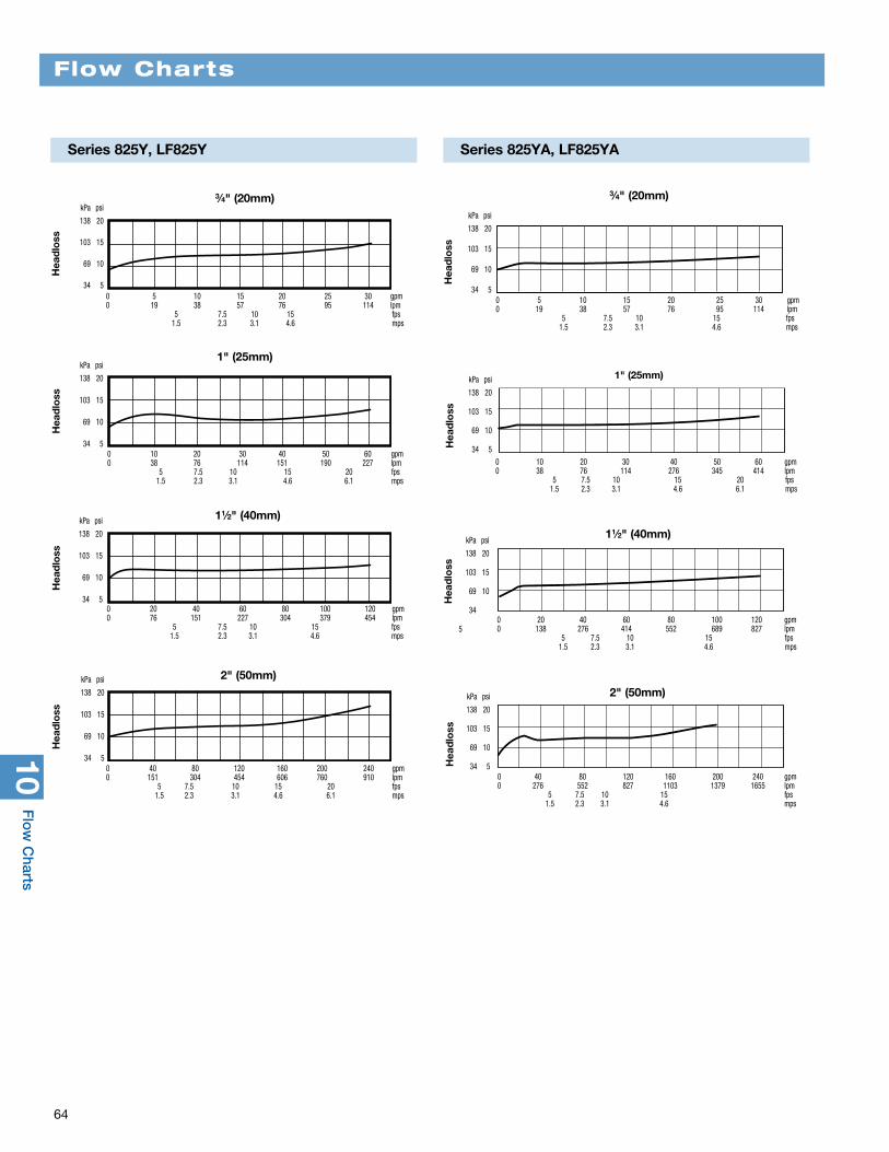
10F
low
Charts
64
Flow Charts
3⁄4" (20mm) kPa psi
138 20
103 15
69 10
34 5 0 5 10 15 20 25 30 gpm 0 19 38 57 76 95 114 lpm 5 7.5 10 15 fps 1.5 2.3 3.1 4.6 mps
Hea
dlo
ss
1" (25mm)
11⁄2" (40mm)
2" (50mm)
0 10 20 30 40 50 60 gpm 0 38 76 114 151 190 227 lpm 5 7.5 10 15 20 fps 1.5 2.3 3.1 4.6 6.1 mps
0 20 40 60 80 100 120 gpm 0 76 151 227 304 379 454 lpm 5 7.5 10 15 fps 1.5 2.3 3.1 4.6 mps
kPa psi
138 20
103 15
69 10
34 5
kPa psi
138 20
103 15
69 10
34 5
kPa psi
138 20
103 15
69 10
34 50 40 80 120 160 200 240 gpm 0 151 304 454 606 760 910 lpm 5 7.5 10 15 20 fps 1.5 2.3 3.1 4.6 6.1 mps
Hea
dlo
ssH
ead
loss
Hea
dlo
ss
Hea
dlo
ss
3⁄4" (20mm)
0 5 10 15 20 25 30 gpm 0 19 38 57 76 95 114 lpm 5 7.5 10 15 fps 1.5 2.3 3.1 4.6 mps
Hea
dlo
ss
1" (25mm)
Hea
dlo
ss
11⁄2" (40mm)
Hea
dlo
ss
2" (50mm)
kPa psi
138 20
103 15
69 10
34 5
kPa psi
138 20
103 15
69 10
34 50 10 20 30 40 50 60 gpm 0 38 76 114 276 345 414 lpm 5 7.5 10 15 20 fps 1.5 2.3 3.1 4.6 6.1 mps
kPa psi
138 20
103 15
69 10
34
5 0 20 40 60 80 100 120 gpm 0 138 276 414 552 689 827 lpm 5 7.5 10 15 fps 1.5 2.3 3.1 4.6 mps
kPa psi
138 20
103 15
69 10
34 50 40 80 120 160 200 240 gpm 0 276 552 827 1103 1379 1655 lpm 5 7.5 10 15 fps 1.5 2.3 3.1 4.6 mps
Series 825Y, LF825Y Series 825YA, LF825YA
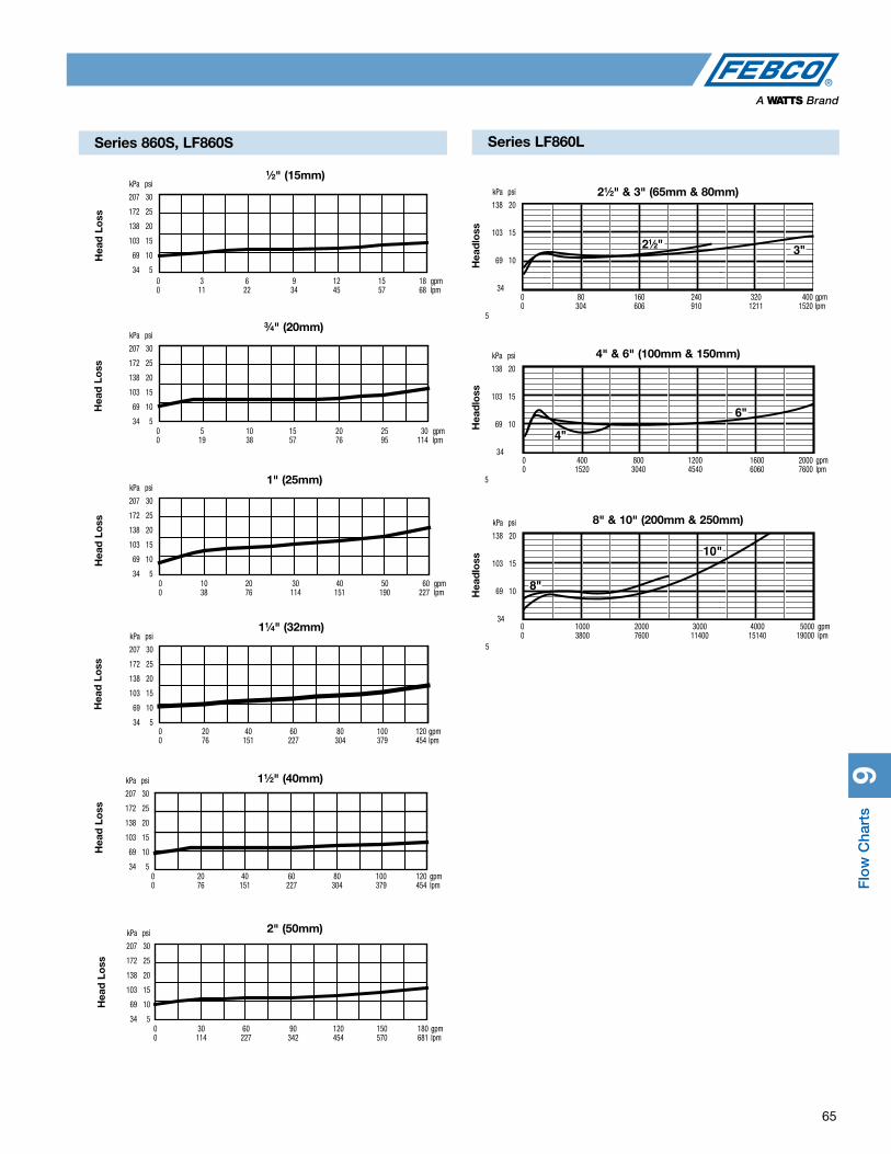
Flo
w C
hart
s9
65
Series 860S, LF860S
0 3 6 9 12 15 18 gpm 0 11 22 34 45 57 68 lpm
1⁄2" (15mm) kPa psi
207 30
172 25
138 20
103 15
69 10
34 5
0 5 10 15 20 25 30 gpm 0 19 38 57 76 95 114 lpm
3⁄4" (20mm) kPa psi
207 30
172 25
138 20
103 15
69 10
34 5
0 10 20 30 40 50 60 gpm 0 38 76 114 151 190 227 lpm
1" (25mm) kPa psi
207 30
172 25
138 20
103 15
69 10
34 5
0 20 40 60 80 100 120 gpm 0 76 151 227 304 379 454 lpm
11⁄4" (32mm) kPa psi
207 30
172 25
138 20
103 15
69 10
34 5
0 20 40 60 80 100 120 gpm 0 76 151 227 304 379 454 lpm
11⁄2" (40mm) kPa psi
207 30
172 25
138 20
103 15
69 10
34 5
0 30 60 90 120 150 180 gpm 0 114 227 342 454 570 681 lpm
2" (50mm) kPa psi
207 30
172 25
138 20
103 15
69 10
34 5
Hea
d L
oss
Hea
d L
oss
Hea
d L
oss
Hea
d L
oss
Hea
d L
oss
Hea
d L
oss
21⁄2" 3"
21⁄2" & 3" (65mm & 80mm) kPa psi
138 20
103 15
69 10
34
5
0 80 160 240 320 400 gpm 0 304 606 910 1211 1520 lpm
Hea
dlo
ss
4" & 6" (100mm & 150mm)
0 400 800 1200 1600 2000 gpm 0 1520 3040 4540 6060 7600 lpm
Hea
dlo
ss
8" & 10" (200mm & 250mm)
0 1000 2000 3000 4000 5000 gpm 0 3800 7600 11400 15140 19000 lpm
Hea
dlo
ss
Series LF860L
kPa psi
138 20
103 15
69 10
34
5
kPa psi
138 20
103 15
69 10
34
5
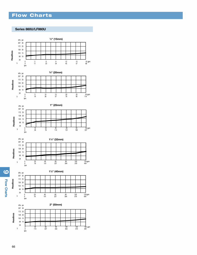
9F
low
Charts
66
Flow Charts
kPa psi
207 30
172 25
138 20
103 15
69 10
34
5
kPa psi
207 30
172 25
138 20
103 15
69 10
34
5 0 5 10 15 20 25 30 gpm 0 19 38 57 76 95 114 lpm
Hea
dlo
ss
1⁄2" (15mm)
0 3 6 9 12 15 18 gpm 0 11 23 34 45 57 68 lpm
Hea
dlo
ss
kPa psi
207 30
172 25
138 20
103 15
69 10
34
5 0 20 40 60 80 100 120 gpm 0 76 151 227 304 379 454 lpm
Hea
dlo
ss
0 20 40 60 80 100 120 gpm 0 76 151 227 304 379 454 lpm
Hea
dlo
ss
kPa psi
207 30
172 25
138 20
103 15
69 10
34
5
kPa psi
207 30
172 25
138 20
103 15
69 10
34
5
1" (25mm)
0 10 20 30 40 50 60 gpm 0 38 76 114 151 190 227 lpm
Hea
dlo
ss
11⁄4" (32mm)
11⁄2" (40mm)
kPa psi
207 30
172 25
138 20
103 15
69 10
34
5 0 30 60 90 120 150 180 gpm 0 114 227 342 454 570 681 lpm
Hea
dlo
ss
2" (50mm)
3⁄4" (20mm)
Series 860U/LF860U
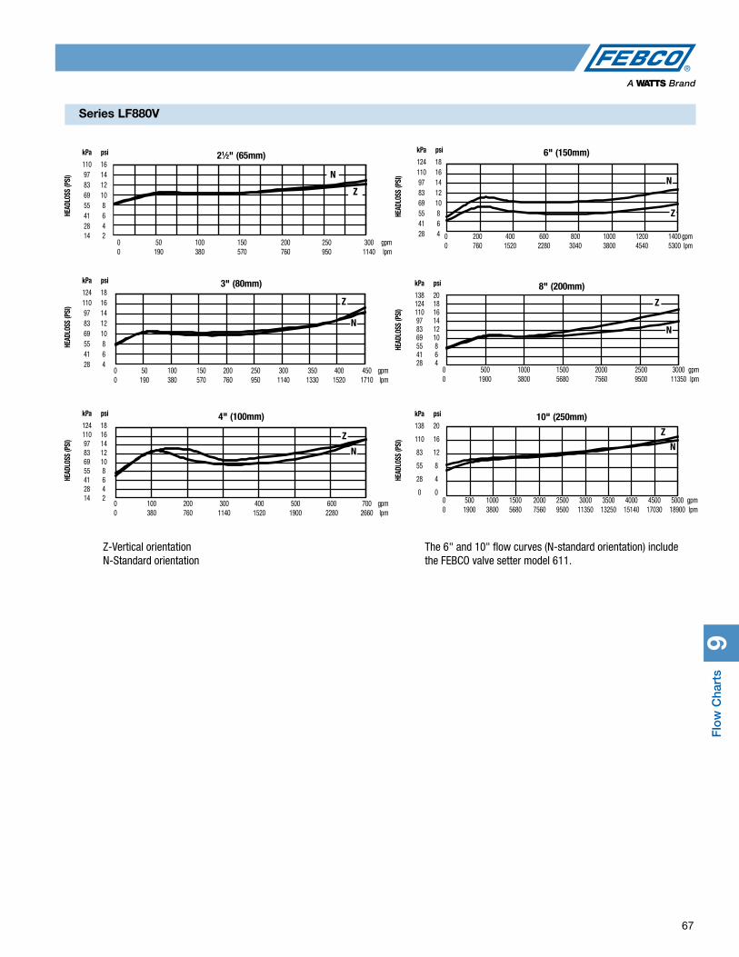
Flo
w C
hart
s9
67
Series LF880V
4681012141618
0 200 400 600 800 1000 1200 1400
468101214161820
0 500 1000 1500 2000 2500 3000
N
Z
N
Z
The 6" and 10" flow curves (N-standard orientation) include the FEBCO valve setter model 611.
Z-Vertical orientation N-Standard orientation
N
Z
N
Z
Z
NN
Z
21⁄2" (65mm) kPa psi
110 16 97 14 83 12 69 10 55 8 41 6 28 4 14 2
0 50 100 150 200 250 300 gpm 0 190 380 570 760 950 1140 lpm
HEAD
LOSS
(PSI
)
3" (80mm) kPa psi
124 18 110 16 97 14 83 12 69 10 55 8 41 6 28 4
0 50 100 150 200 250 300 350 400 450 gpm 0 190 380 570 760 950 1140 1330 1520 1710 lpm
HEAD
LOSS
(PSI
)HE
ADLO
SS (P
SI)
4" (100mm) kPa psi
124 18 110 16 97 14 83 12 69 10 55 8 41 6 28 4 14 2
0 100 200 300 400 500 600 700 gpm 0 380 760 1140 1520 1900 2280 2660 lpm
6" (150mm) kPa psi
124 18 110 16 97 14 83 12 69 10 55 8 41 6 28 4 0 200 400 600 800 1000 1200 1400 gpm
0 760 1520 2280 3040 3800 4540 5300 lpm
HEAD
LOSS
(PSI
)HE
ADLO
SS (P
SI)
HEAD
LOSS
(PSI
)
8" (200mm) kPa psi
138 20 124 18 110 16 97 14 83 12 69 10 55 8 41 6 28 4
0 500 1000 1500 2000 2500 3000 gpm 0 1900 3800 5680 7560 9500 11350 lpm
10" (250mm) kPa psi
138 20
110 16
83 12
55 8
28 4
0 0 0 500 1000 1500 2000 2500 3000 3500 4000 4500 5000 gpm 0 1900 3800 5680 7560 9500 11350 13250 15140 17030 18900 lpm

9F
low
Charts
68
Flow Charts
21⁄2" (65mm) kPa psi
137 20
103 15
69 10
34 5 0 50 100 150 200 250 gpm 0 190 380 570 760 950 lpm
Hea
dlo
ss
3" (80mm) kPa psi
172 25
137 20
103 15
69 10 0 100 200 300 400 500 gpm 0 380 760 1135 1520 1900 lpm
Hea
dlo
ss
4" (100mm) kPa psi
137 20
103 15
69 10
34 5 0 120 240 360 480 600 gpm 0 455 910 1370 1820 2270 lpm
Hea
dlo
ss
6" (150mm) kPa psi
137 20
103 15
69 10
34 5 0 300 600 900 1200 1500 gpm 0 1135 2270 3405 4540 5680 lpm
Hea
dlo
ss
8" (200mm) kPa psi
137 20
103 15
69 10
34 5 0 600 1200 1800 2400 3000 gpm 0 2270 4540 6810 9080 11400 lpm
Hea
dlo
ss
10" (250mm) kPa psi
172 25
137 20
103 15
69 10 0 1000 2000 3000 4000 5000 gpm 0 3800 7600 11400 15140 19000 lpm
Hea
dlo
ss
1⁄2" (15mm) kPa psi
103 15
69 10
35 5
0 0 0 3 6 9 12 15 18 gpm 0 11 23 34 45 57 68 lpm 5 7.5 10 15 20 fps 1.5 2.3 3.1 4.6 6.1 mps
Hea
dlo
ss
3⁄4" (20mm) kPa psi
103 15
69 10
34 5
0
0
Hea
dlo
ss1" (25mm) kPa psi
103 15
69 10
34 5
0
0
Hea
dlo
ss
11⁄4" (32mm) kPa psi
103 15
69 10
34 5
0
0
Hea
dlo
ss
11⁄2" (40mm) kPa psi
103 15
69 10
34 5
0
0
Hea
dlo
ss
2" (50mm) kPa psi
103 15
69 10
34 5
0
0
Hea
dlo
ss
0 4 8 12 16 20 24 gpm 0 15 30 45 61 76 91 lpm 5 7.5 10 fps 1.5 2.3 3.1 mps
0 8 16 24 32 40 48 gpm 0 30 61 91 121 151 182 lpm 5 7.5 10 15 fps 1.5 2.3 3.1 4.6 mps
0 20 40 60 80 gpm 0 76 151 227 304 lpm 5 7.5 10 15 fps 1.5 2.3 3.1 4.6 mps
0 20 40 60 80 100 120 gpm 0 76 151 227 304 379 454 lpm 5 7.5 10 15 fps 1.5 2.3 3.1 4.6 mps
0 30 60 90 120 150 180 gpm 0 114 227 342 454 570 681 lpm 5 7.5 10 15 fps 1.5 2.3 3.1 4.6 mps
826YD 710, 715
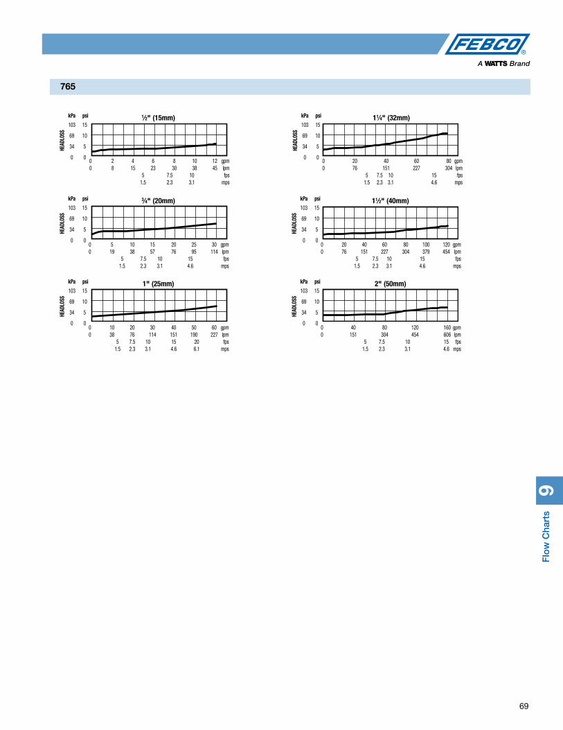
Flo
w C
hart
s9
69
765
3⁄4" (20mm) kPa psi
103 15
69 10
34 5
0 0
HEAD
LOSS
1⁄2" (15mm) kPa psi
103 15
69 10
34 5
0 0 0 2 4 6 8 10 12 gpm 0 8 15 23 30 38 45 lpm 5 7.5 10 fps 1.5 2.3 3.1 mps
HEAD
LOSS
0 5 10 15 20 25 30 gpm 0 19 38 57 76 95 114 lpm 5 7.5 10 15 fps 1.5 2.3 3.1 4.6 mps
1" (25mm) kPa psi
103 15
69 10
34 5
0 0
HEAD
LOSS
0 10 20 30 40 50 60 gpm 0 38 76 114 151 190 227 lpm 5 7.5 10 15 20 fps 1.5 2.3 3.1 4.6 6.1 mps
11⁄4" (32mm) kPa psi
103 15
69 10
34 5
0 0 0 20 40 60 80 gpm 0 76 151 227 304 lpm 5 7.5 10 15 fps 1.5 2.3 3.1 4.6 mps
HEAD
LOSS
11⁄2" (40mm) kPa psi
103 15
69 10
34 5
0 0
HEAD
LOSS
0 20 40 60 80 100 120 gpm 0 76 151 227 304 379 454 lpm 5 7.5 10 15 fps 1.5 2.3 3.1 4.6 mps
2" (50mm) kPa psi
103 15
69 10
34 5
0 0
HEAD
LOSS
0 40 80 120 160 gpm 0 151 304 454 606 lpm 5 7.5 10 15 fps 1.5 2.3 3.1 4.6 mps

9F
low
Charts
70
Flow Charts
1" (25mm) kPa psi 96 14 83 12 69 10 55 8 41 6 28 4 14 2 0 0
0 10 20 30 40 50 60 gpm0 38 76 114 152 190 228 lpm 5 7.5 10 15 20 fps 1.5 2.3 3.0 4.6 6.1 mps
*
kPa psi
96 14 83 12 69 10 55 8 41 6 28 4 14 2 0 0
*11⁄2" (40mm)
0 10 20 30 40 50 60 70 80 90 100 110 120 gpm0 38 76 114 152 190 228 266 304 342 380 418 450 lpm 5 7.5 10 15 fps 1.5 2.3 3.0 4.6 mps
*
0 10 20 30 40 50 60 70 80 gpm0 38 76 114 152 190 228 266 304 lpm 5 7.5 10 15 fps 1.5 2.3 3.0 4.6 mps
11⁄4" (32mm)kPa psi
69 10
55 8
41 6
28 4
14 2
0 0
*
0 20 40 60 80 100 120 140 160 180 gpm0 76 152 228 304 380 450 532 608 684 lpm 5 7.5 10 15 fps 1.5 2.3 3.0 4.6 mps
2" (50mm) kPa psi
96 14 83 12 69 10 55 8 41 6 28 4 14 2 0 0
*3⁄4" (20mm) kPa psi
96 14 83 12 69 10 55 8 41 6 28 4 14 2 0 0
0 5 10 15 20 25 30 35 gpm0 19 38 57 76 95 114 113 lpm 5 7.5 10 15 20 fps 1.5 2.3 3.0 4.6 6.1 mps
Series LF767FR
kPa psi
96 14 83 12 69 10 55 8 41 6 28 4 14 2 0 0
0 5 10 15 20 gpm0 19 38 57 76 lpm 5 7.5 10 15 20 fps 1.5 2.3 3.0 4.6 6.1 ps
*1⁄2" (15mm)
0
3.8
7.6
11.4
15.1
18.9
22.7
26.5
30.3
34.1
0
1
2
3
4
5
6
7
8
9
0 1.38 2.76 4.14 5.52 6.89 8.27 9.65 11.03 12.410 20 40 60 80 100 120 140 160 180
barpsi
Line Pressure
Flow
lpm gpm
FPTC-1
Discharge Rate (Full Open)
Series LF622
kPa psi
241 35
207 30
172 25
138 20
103 15
69 10
34 5
0 0
*
5 10 15 20 25 30 35 40 45 gpm 19 38 57 76 95 114 133 152 171 lpm 5 (7.5) 15 fps 1.5 2.3 4.6 mps
3⁄4" and 1" (20, 25mm)
bar psi
41.4 600
34.5 500
27.6 400
20.7 300
13.8 200
6.9 100
0 0 0 50 100 150 200 250 300 350 400 450 ºF -17.8 10 38 68 85 121 149 177 204 232 ºC
Seat Rating
Series FPHB-1
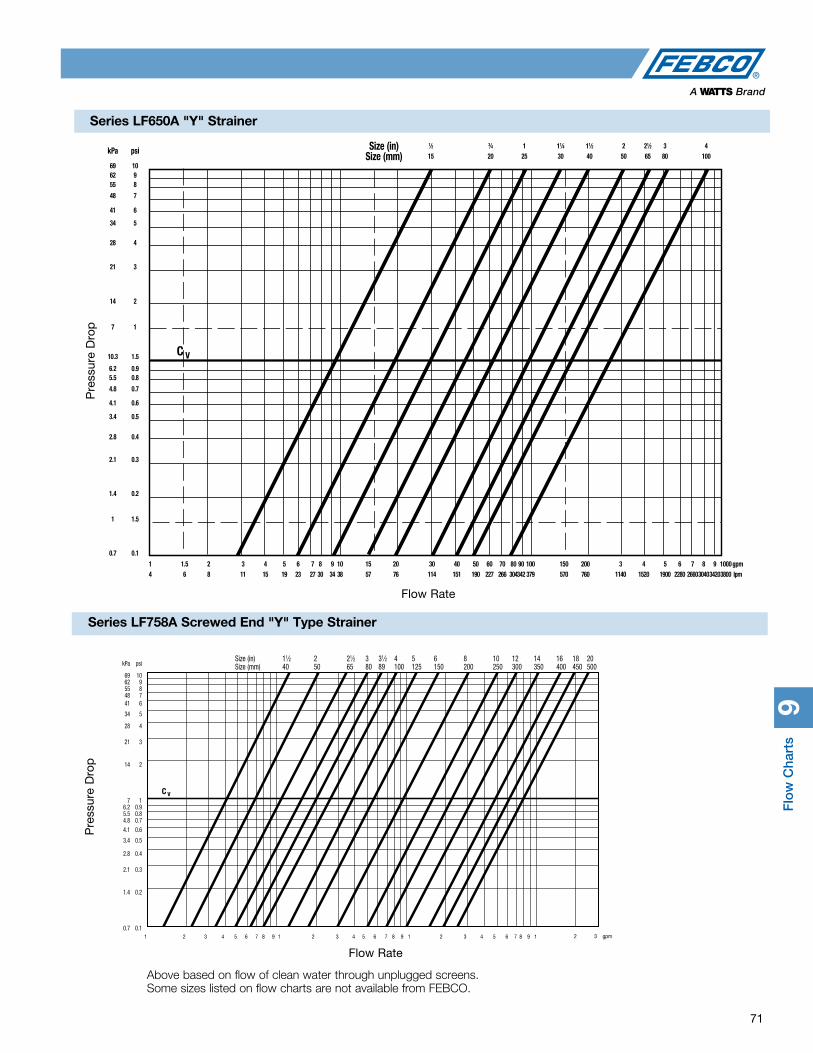
Flo
w C
hart
s9
71
Series LF650A "Y" Strainer
Pre
ssur
e D
rop
Flow Rate
1⁄2
15 69 10
kPa psi Size (in)
Size (mm)3⁄4
201
2511⁄4
3011⁄2
402
5021⁄2
653
804
100
62 9 55 8
48 7
41 6
34 5
28 4
21 3
14 2
7 1
6.2 0.9 5.5 0.8
4.8 0.7
4.1 0.6
3.4 0.5
2.8 0.4
2.1 0.3
1.4 0.2
1 1.5
0.7 0.1
1
41.5
62
83
114
155
196
237
278
309
3410
3815
5720
7630
11440
15150
19060
22770
26680
30490
342 100
379 150
570 200
760 3
1140 4
1520 5
1900 6
2280 7
2660 8
3040 1000
3800
10.3 1.5
9
3420 gpm
lpm
kPa psi
69 10 62 9 55 8 48 7 41 6
34 5
28 4
21 3
14 2
7 1 6.2 0.9 5.5 0.8 4.8 0.7 4.1 0.6
3.4 0.5
2.8 0.4
2.1 0.3
1.4 0.2
0.7 0.187 9
11⁄2 40
2 50
21⁄2 65
3 80
31⁄2 89
4 100
5 125
6 150
8 200
10 250
12 300
14 350
16 400
18 450
20 500
Size (in) Size (mm)
Pre
ssur
e D
rop
1 2 3 4 5 6 7 8 9 1 2 3 4 5 6 7 8 9 1 2 3 4 5 6 1 2 3 gpm
Flow Rate
Above based on flow of clean water through unplugged screens. Some sizes listed on flow charts are not available from FEBCO.
Series LF758A Screwed End "Y" Type Strainer

C-FEBCO 1350 MF#10105 © 2017 FEBCO
USA: T: (800) 767-1234 • F: (800) 788-4491 • FEBCOonline.comCanada: T: (905) 332-4090 • F: (905) 332-7068 • FEBCOonline.ca
Latin America: (52) 81-1001-8600 • F: (52) 81-8000-7091 • FEBCOonline.com


