
IndustrialHydraulics
Electric Drivesand Controls
Linear Motion andAssembly Technologies
ServiceAutomation
MobileHydraulicsPneumatics
Ball Rail TablesMaintenance Manual
Mounting
The Drive and Control Company
1. Safety, Cross-References and Symbols 21.1 Safety notes and their symbols 21.2 Cross-referencing symbols 21.3 Symbols 2
2. Overview of Ball Rail Tables 32.1 Type Overview 32.2 Nameplate, Ordering of Spare Parts 32.3 Ordering of Components and Catalogs 3
3. Ball Rail Tables Fixings 43.1 Fixing the ball rail tables 43.2 Transport protection 4
4. Overview of accessories andattachments 5
5. Mounting the switching system 65.1 Mounting internal switches 65.2 Mounting external switches 65.3 Adjusting the switches 75.4 Mounting the socket 75.5 Mounting and dismantling the cable duct 8
6. Mounting the drive 96.1 Mounting the motor complete with motor mount
and bellows coupling 96.2 Mounting the motor complete with motor mount
and push-fit coupling 106.3 Dismantling a motor with motor mount 106.4 Mounting the motor with timing belt side drive 116.5 Dismantling the motor and timing belt side drive 12
7. Maintenance 13
8. Mounting assemblies and wear parts 148.1 Overview 148.2 Dismantling/mounting bellows 158.3 Replacing the fixed bearing 168.4 Replacing the floating bearing 178.5 Replacing the ball screw drive (BSD) 178.6 Replacing the sealing strip 178.7 Replacing the guide rail, carriage or base plate 17
9. Mounting X-Y tables 189.1 Mounting two ball rail tables of the same size
(base plate on carriage) 199.2 Mounting a ball rail table of the next smaller size
(base plate on carriage) 209.3 Mounting two ball rail tables of the same size
(carriage to carriage) 209.4 Mounting a ball rail table of the next smaller size
(carriage to carriage) 20
2
1. Safety, Cross-References and Symbols
1.1 Safety notes and their symbols
The following symbols are used to identify safety notes:
DANGER !Risk of coming into contact with power-conducting parts! Cut off power supply!
WARNING!Risk of injury!
Caution!Risk of damage to Ball Rail Tableor adjoining structures!
Caution!Keep Ball Rail Table clean!If necessary, cover it over!
1.2 Cross-referencing symbols
The symbols below are used to refer to repeat or follow-on workoperations:
! 5.4 See Section 5.4
! 5.4.2 See Figure 5.4.2(Figure 2 in Section 5.4)
Note, recommendation
1.3 Symbols
Screw friction factor 0.125Strength class 8.8
u Tightening Torque
2.3
2.1
STARDeutsche Star GmbhD-97419 SchweinfurtTel. 09721/9370 - Fax 937350
1460-305-0052278/3
06.02.1997
TYPID - NrDatum
STAR - matic
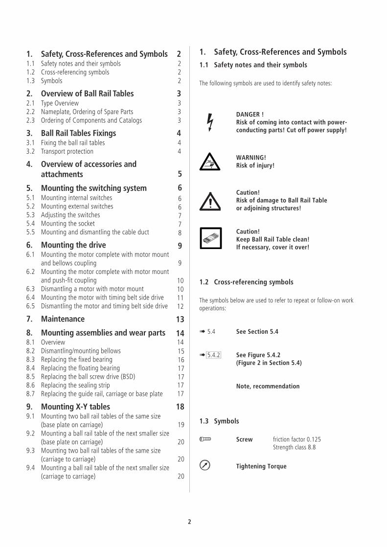
TKK 15 - 155 Al
TKK 20 - 225 Al, TKK 20 - 225 St
TKK 20 - 225 Al
TKK 30 - 325 Al, TKK 30 - 325 St
TKK 30 - 325 Al
TKK 35 - 455 Al
7510
590
120
120
L
L
L
L
L
35 35
3030
3030
20 20
20 20
155
225
225
325
325
455
60
L
123
2. Overview of Ball RailTables
2.1 Type Overview
Ball rail tables are available in four sizesand in some cases in different heights. Forprecise data and dimensions, please referto the "Ball Rail Tables" Catalog.
In the present document, only the ball railtables with ball screw drive (BSD) areillustrated.
Bosch Rexroth Ball Rail Tables canbe mounted and maintained by suitablytrained technical personnel with the aidof this manual.
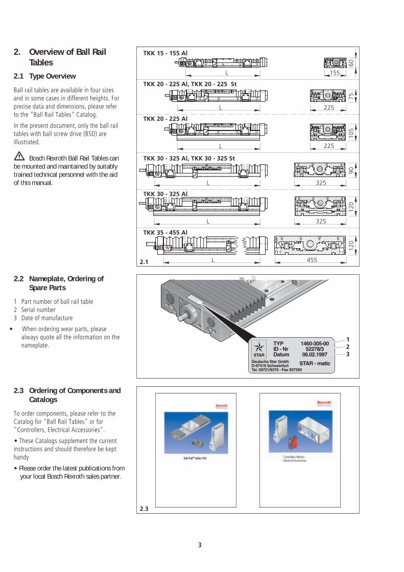
2.2 Nameplate, Ordering ofSpare Parts
1 Part number of ball rail table2 Serial number3 Date of manufacture
• When ordering wear parts, pleasealways quote all the information on thenameplate.
2.3 Ordering of Components andCatalogs
To order components, please refer to theCatalog for "Ball Rail Tables" or for"Controllers, Electrical Accessories".
• These Catalogs supplement the currentinstructions and should therefore be kepthandy
• Please order the latest publications fromyour local Bosch Rexroth sales partner.
3

1
2
3
rmax. 0,3
3.3
Aluminium version, secured from above
Steel version, secured from above
Aluminium version, secured from below
1
2
3
rmax. 0,3
4
1
2
3
rmax. 0,3
3.1.3
3.1.2
3.1.1
3. Ball Rail Tables Fixings
3.1 Fixing the ball rail tables
1 Plug2 Base plate3 Reference edge4 T-nutBall rail tables made of profiled aluminumcan be fixed either… from above (! 3.1.1 )… or from below (! 3.1.2 ).Steel ball rail tables can be fixed only fromabove (! 3.1.3 ).In both versions, a reference edge is builtinto the base plate to help align the unit.The mounting plugs are supplied with theunit.The T-nuts are available as accessories.All connection dimensions are specified inthe "Ball Rail Tables" Catalog.
Please also note the specialconnection system for ball rail tables: thissystem permits the assemblies to movealong several different axes.
Tightening torques for the fixingscrewsfor friction factor 0.125strength class 8.8 /
Screw M 6 M 8 M 10 M 16
Torque in Nm 9,5 23 46 195
3.2 Transport protection
Warning! Before starting up thedrive, remove the protective transportpacking.
4

4.2
1
23
4
5
6
7
8
9
10
11
1
23
4
5
7
8
9
1010
Aluminum
Steel
4. Overview of accessoriesand attachments
• If required, the following componentscan be mounted ready for operation. -These Components may also be retro-fitted at any time.
Switching system
1 Mechanical switches, external2 Cable duct3 Switching cam4 Proximity switch, external5 Socket/plug for external switches6 Profiled support7 Socket/plug for internal switches8 Mechanical and proximity
switches, internal
! 5.
Drive
9 Motor mount and coupling10 Motor11 Timing belt side drive
! 6.
Mounting X-Y Units
Last chapter of this manual
5
4.1
5.1.2
23
24
Switching distances
21
2221
22
2,0+
0,2
0,5+
0,2
Switching distances
23 24
2,0+
0,2
0,5+
0,2
6
5.1.1
5. Mounting the switchingsystem
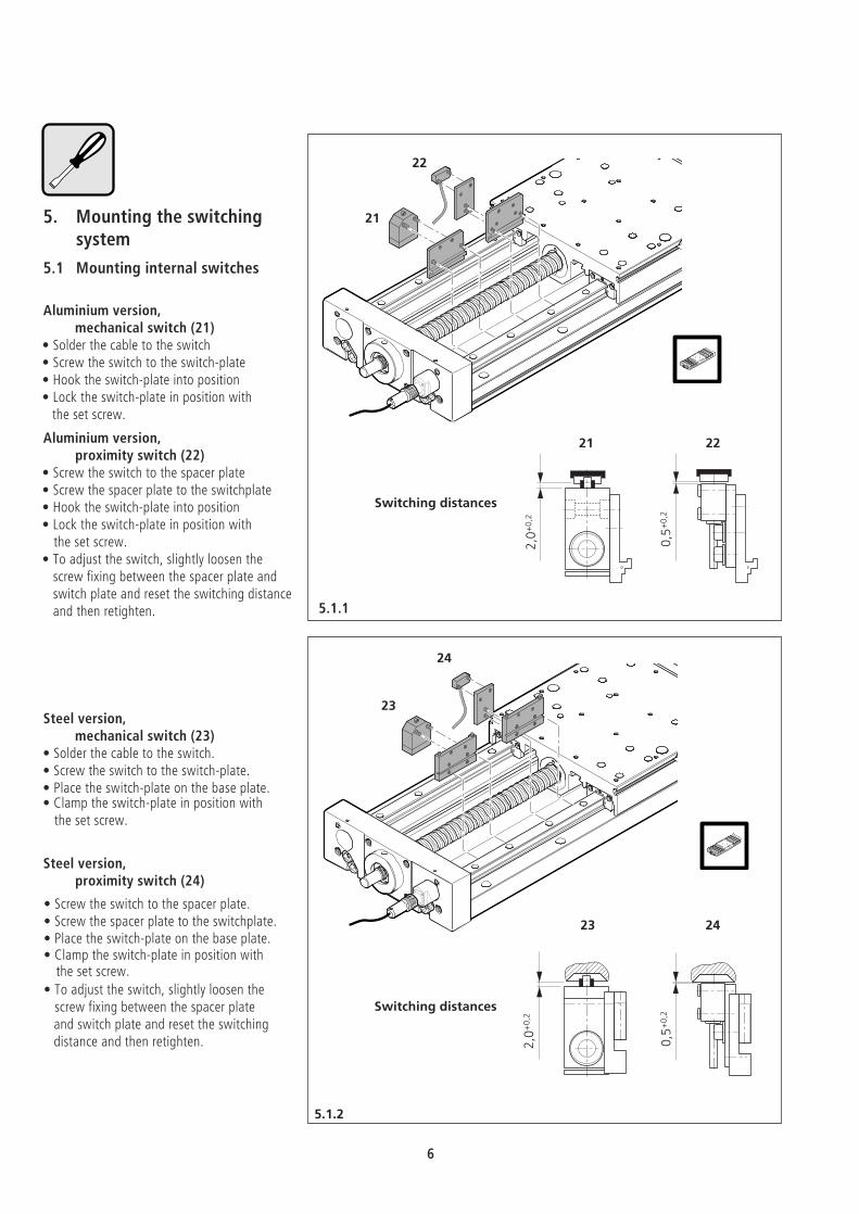
5.1 Mounting internal switches
Aluminium version,mechanical switch (21)
• Solder the cable to the switch• Screw the switch to the switch-plate• Hook the switch-plate into position• Lock the switch-plate in position with
the set screw.
Aluminium version,proximity switch (22)
• Screw the switch to the spacer plate• Screw the spacer plate to the switchplate• Hook the switch-plate into position• Lock the switch-plate in position with
the set screw.• To adjust the switch, slightly loosen the
screw fixing between the spacer plate andswitch plate and reset the switching distanceand then retighten.
Steel version,mechanical switch (23)
• Solder the cable to the switch.• Screw the switch to the switch-plate.• Place the switch-plate on the base plate.• Clamp the switch-plate in position with
the set screw.
Steel version,proximity switch (24)
• Screw the switch to the spacer plate.• Screw the spacer plate to the switchplate.• Place the switch-plate on the base plate.• Clamp the switch-plate in position with
the set screw.
• To adjust the switch, slightly loosen thescrew fixing between the spacer plateand switch plate and reset the switchingdistance and then retighten.
5.3
5.2.1
5.2.2
31
32
33
34
2,5±0
,2
Switching distances
31
32
0,4+
0,2
Switching distances
2,5±0,2
0,4+0,2
33
34
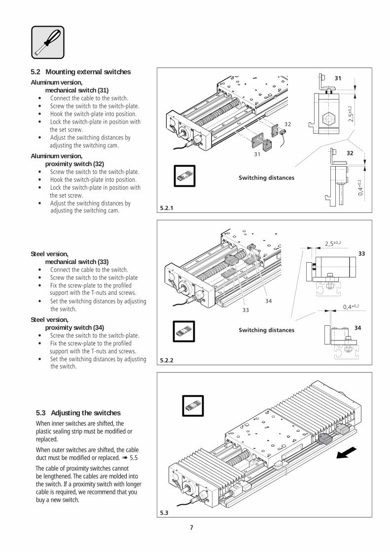
5.2 Mounting external switches
Aluminum version,mechanical switch (31)
• Connect the cable to the switch.• Screw the switch to the switch-plate.• Hook the switch-plate into position.• Lock the switch-plate in position with
the set screw.• Adjust the switching distances by
adjusting the switching cam.
Aluminum version,proximity switch (32)
• Screw the switch to the switch-plate.• Hook the switch-plate into position.• Lock the switch-plate in position with
the set screw.• Adjust the switching distances by
adjusting the switching cam.
Steel version,mechanical switch (33)
• Connect the cable to the switch.• Screw the switch to the switch-plate• Fix the screw-plate to the profiled
support with the T-nuts and screws.
• Set the switching distances by adjustingthe switch.
Steel version,proximity switch (34)
• Screw the switch to the switch-plate.• Fix the screw-plate to the profiled
support with the T-nuts and screws.• Set the switching distances by adjusting
the switch.
5.3 Adjusting the switchesWhen inner switches are shifted, theplastic sealing strip must be modified orreplaced.When outer switches are shifted, the cableduct must be modified or replaced.! 5.5The cable of proximity switches cannotbe lengthened. The cables are molded intothe switch. If a proximity switch with longer cable is required, we recommend that you buy a new switch.
7
5.4.2
5.4.1
5.4.3
internal
external
Socket and plug
1
2
34
5
6
789
10
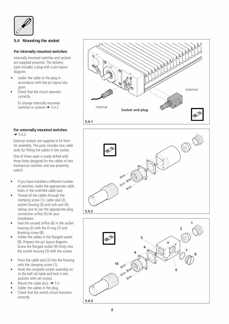
5.4 Mounting the socket
For internally mounted switches:
Internally mounted switches and socketsare supplied prewired. The deliverypack includes a plug with a pin layoutdiagram.
• Solder the cable to the plug inaccordance with the pin layout dia-gram.
• Check that the circuit operatescorrectly.
To change internally mountedswitches or sockets ! 5.4.2
For externally mounted switches! 5.4.3
External sockets are supplied in kit formfor assembly. The pack includes two cableseals for fitting the cables in the socket.
One of these seals is ready-drilled withthree holes designed for the cables of twomechanical switches and one proximityswitch.
• If you have installed a different numberof switches, make the appropriate cableholes in the undrilled cable seal.
• Thread all the cables through theclamping screw (1), cable seal (2),socket housing (3) and cork seal (4),taking care to use the appropriate plugconnection orifice (5) for yourinstallation.
• Seal the unused orifice (6) in the socket
housing (3) with the O-ring (7) andblanking screw (8).
• Solder the cables in the flanged socket
(9). Prepare the pin layout diagram.Screw the flanged socket (9) firmly intothe socket housing (3) with the screws
• Press the cable seal (2) into the housingwith the clamping screw (1).
• Hook the complete socket assembly onto the ball rail table and lock it intoposition with set screws.
• Mount the cable duct.! 5.5• Solder the cables in the plug.• Check that the switch circuit functions
correctly.
8
5.5.3
5.5.1
5.5.2
300
18 ±0,5
12
5
24
9,5
9
R 1,5
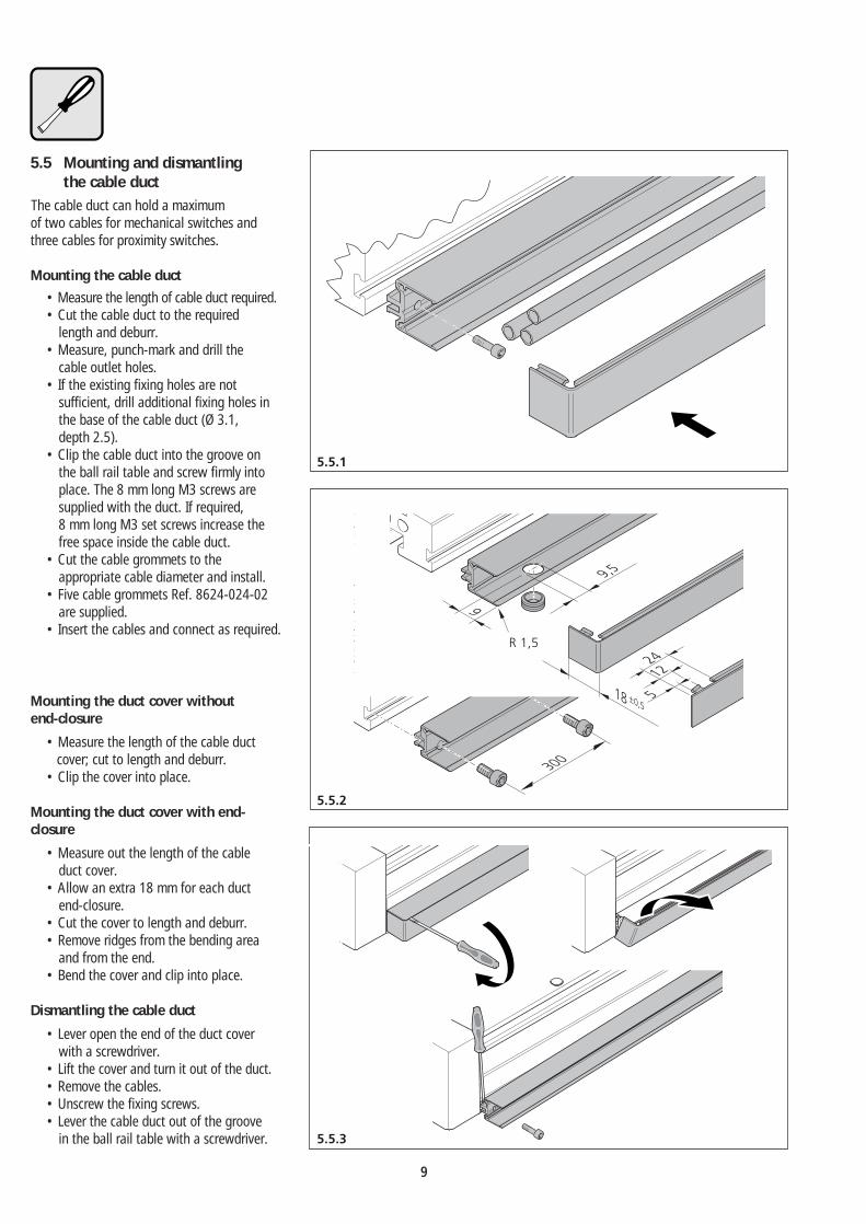
5.5 Mounting and dismantlingthe cable duct
The cable duct can hold a maximumof two cables for mechanical switches andthree cables for proximity switches.
Mounting the cable duct• Measure the length of cable duct required.• Cut the cable duct to the required
length and deburr.• Measure, punch-mark and drill the
cable outlet holes.• If the existing fixing holes are not
sufficient, drill additional fixing holes inthe base of the cable duct (Ø 3.1,depth 2.5).
• Clip the cable duct into the groove onthe ball rail table and screw firmly intoplace. The 8 mm long M3 screws aresupplied with the duct. If required,8 mm long M3 set screws increase thefree space inside the cable duct.
• Cut the cable grommets to theappropriate cable diameter and install.
• Five cable grommets Ref. 8624-024-02are supplied.
• Insert the cables and connect as required.
Mounting the duct cover withoutend-closure
• Measure the length of the cable ductcover; cut to length and deburr.
• Clip the cover into place.
Mounting the duct cover with end-closure
• Measure out the length of the cableduct cover.
• Allow an extra 18 mm for each ductend-closure.
• Cut the cover to length and deburr.• Remove ridges from the bending area
and from the end.• Bend the cover and clip into place.
Dismantling the cable duct• Lever open the end of the duct cover
with a screwdriver.• Lift the cover and turn it out of the duct.• Remove the cables.• Unscrew the fixing screws.• Lever the cable duct out of the groove
in the ball rail table with a screwdriver.
9
6.2.1
6.1.3
6.1.1
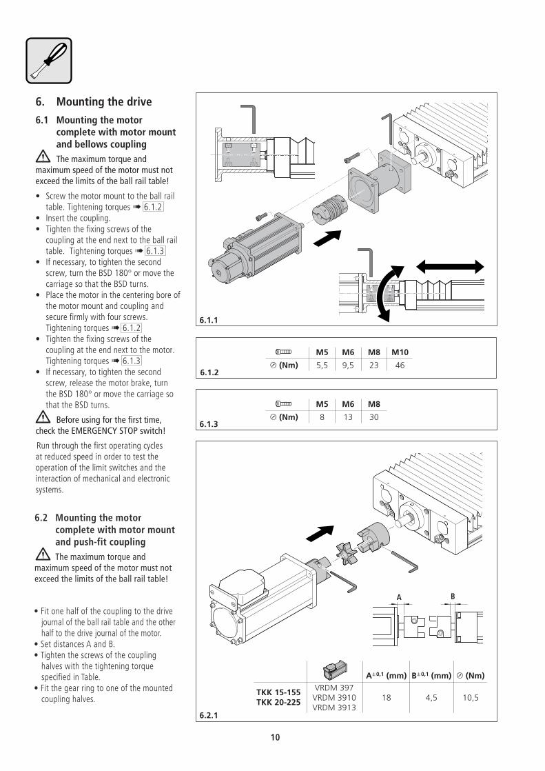
A± 0,1 (mm) B± 0,1 (mm) u (Nm)VRDM 397TKK 15-155
VRDM 3910 18 4,5 10,5TKK 20-225VRDM 3913
M5 M6 M8 M10
u (Nm) 5,5 9,5 23 46
M5 M6 M8
u (Nm) 8 13 30
6.1.2
A B
6. Mounting the drive6.1 Mounting the motor
complete with motor mountand bellows couplingThe maximum torque and
maximum speed of the motor must notexceed the limits of the ball rail table!
• Screw the motor mount to the ball railtable. Tightening torques ! 6.1.2
• Insert the coupling.• Tighten the fixing screws of the
coupling at the end next to the ball railtable. Tightening torques ! 6.1.3
• If necessary, to tighten the secondscrew, turn the BSD 180° or move thecarriage so that the BSD turns.
• Place the motor in the centering bore ofthe motor mount and coupling andsecure firmly with four screws.Tightening torques ! 6.1.2
• Tighten the fixing screws of thecoupling at the end next to the motor.Tightening torques ! 6.1.3
• If necessary, to tighten the secondscrew, release the motor brake, turnthe BSD 180° or move the carriage sothat the BSD turns.
Before using for the first time,check the EMERGENCY STOP switch!
Run through the first operating cyclesat reduced speed in order to test theoperation of the limit switches and theinteraction of mechanical and electronicsystems.
6.2 Mounting the motorcomplete with motor mountand push-fit coupling
The maximum torque andmaximum speed of the motor must notexceed the limits of the ball rail table!
• Fit one half of the coupling to the drivejournal of the ball rail table and the otherhalf to the drive journal of the motor.
• Set distances A and B.• Tighten the screws of the coupling
halves with the tightening torquespecified in Table.
• Fit the gear ring to one of the mountedcoupling halves.
10

6.3
6.2.2
6.2.3
M5 M6 M8 M10
u (Nm) 5,5 9,5 23 46
M5 M6 M8 M10
u (Nm) 5,5 9,5 23 46
STAR
STAR
STAR
STAR
STAR
STAR
STAR
STAR
Mounting the motor complete withmotor mount and push-fit coupling(continuation)
• Align the motor so that the twocoupling halves fit into each other, andpress the coupling strongly together sothat the two halves join.
• Align the motor with the centring boreof the motor mount and insert it intothe centring recess. Screw firmly intoplace.
Before using for the first time,check the EMERGENCY STOP switch!Run through the first operating cyclesat reduced speed in order to test theoperation of the limit switches and theinteraction of mechanical and electronicsystems.
• Place the motor mount in the locating
recess of the ball rail table and screwfirmly into place.
6.3 Dismantling a motor withmotor mount
If the ball rail table is mountedvertically or at an inclined angle, thecarriage must be prevented fromcrashing down!
Disconnect from mains!• For the version with bellows coupling
only: loosen the fixing screws of thebellows coupling at the end next to themotor.
• Unscrew the motor from the motormount and remove.
11

6.4.1
6.4.2
A (mm)
M…41…TKK 15-155 MMD 082 A
9,5
M…71… 11M…41…
TKK 20-225 MMD 082 A9,5
M…71… 11TKK 30-325 M…71… 11
M…71… 11,5TKK 35-455M…90… 4,5
A
Type 1
Mounting clamping assembly Type 1Slightly oil the clamping elements.
Do not use oil with MoS2 additives!• Push on the clamping assembly and
slightly tighten the screws. Align the hub• Tighten the screws evenly in diagonally
opposite sequence until all screws aretightened to the specified torque
/
Screw M 4 M 5 M 6
Torque in Nm 2.9 6 10
6.4 Mounting the motor withtiming belt side drive
The maximum torque andmaximum speed of the motor must notexceed the limits of the ball rail table!
Mounting the housing• Screw the housing of the timing belt
side drive to the ball rail table.Tightening torques /
Screw M 6 M 8 M 10
Torque in Nm 9.5 23 46
Mounting the first belt pulley• Fit the belt pulley, complete with
retaining ring, mounted timing belt andclamping assembly on to the journal ofthe ball rail table.
• Set clearance A from the housing.
12
6.4.3
6.4.4
Type 2
B (mm)
M…41…TKK 15-155 MMD 082 A
9
M…71… 10M…41…
TKK 20-225 MMD 082 A9
M…71… 10TKK 30-325 M…71… 10
M…71… 10TKK 35-455M…90… 3
STAR
B
F/
1
2
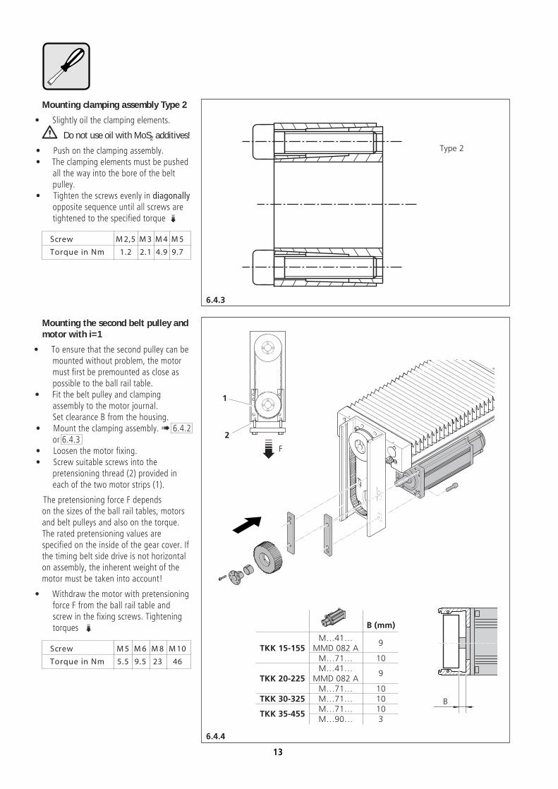
Mounting clamping assembly Type 2• Slightly oil the clamping elements.
Do not use oil with MoS2 additives!• Push on the clamping assembly.• The clamping elements must be pushed
all the way into the bore of the beltpulley.
• Tighten the screws evenly in diagonallyopposite sequence until all screws aretightened to the specified torque /
Screw M 2,5 M 3 M 4 M 5
Torque in Nm 1.2 2.1 4.9 9.7
Mounting the second belt pulley andmotor with i=1
• To ensure that the second pulley can bemounted without problem, the motormust first be premounted as close aspossible to the ball rail table.
• Fit the belt pulley and clampingassembly to the motor journal.Set clearance B from the housing.
• Mount the clamping assembly.! 6.4.2or 6.4.3
• Loosen the motor fixing.• Screw suitable screws into the
pretensioning thread (2) provided ineach of the two motor strips (1).
The pretensioning force F dependson the sizes of the ball rail tables, motorsand belt pulleys and also on the torque.The rated pretensioning values arespecified on the inside of the gear cover. Ifthe timing belt side drive is not horizontalon assembly, the inherent weight of themotor must be taken into account!
• Withdraw the motor with pretensioningforce F from the ball rail table andscrew in the fixing screws. Tighteningtorques /
Screw M 5 M 6 M 8 M 10
Torque in Nm 5.5 9.5 23 46
13
6.4.6
6.4.5
C (mm)
Mƒ 41ƒTK K 15-155 MMD 082 A
16
Mƒ 71ƒ 19Mƒ 41ƒ
TK K 20-225 MMD 082 A16
Mƒ 71ƒ 19TK K 30-325 Mƒ 71ƒ 19
Mƒ 71ƒ 19TK K 35-455
Mƒ 90ƒ 21
C
F/
1
2
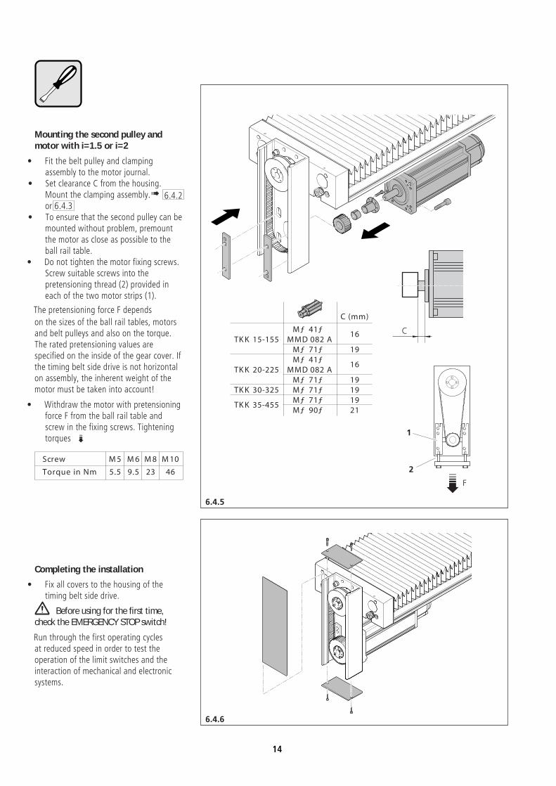
Mounting the second pulley andmotor with i=1.5 or i=2
• Fit the belt pulley and clampingassembly to the motor journal.
• Set clearance C from the housing.Mount the clamping assembly. ! 6.4.2or 6.4.3
• To ensure that the second pulley can bemounted without problem, premountthe motor as close as possible to theball rail table.
• Do not tighten the motor fixing screws.Screw suitable screws into thepretensioning thread (2) provided ineach of the two motor strips (1).
The pretensioning force F depends
on the sizes of the ball rail tables, motorsand belt pulleys and also on the torque.The rated pretensioning values arespecified on the inside of the gear cover. Ifthe timing belt side drive is not horizontalon assembly, the inherent weight of themotor must be taken into account!
• Withdraw the motor with pretensioningforce F from the ball rail table andscrew in the fixing screws. Tighteningtorques /
Screw M 5 M 6 M 8 M 10
Torque in Nm 5.5 9.5 23 46
Completing the installation• Fix all covers to the housing of the
timing belt side drive.
Before using for the first time,check the EMERGENCY STOP switch!Run through the first operating cyclesat reduced speed in order to test theoperation of the limit switches and theinteraction of mechanical and electronicsystems.
14

6.5
STAR
STAR
STAR
STAR
STAR
STAR
STAR
STAR
6.5 Dismantling the motor andtiming belt side drive
If the ball rail table is mountedvertically or at an inclined angle, thecarriage must be prevented fromcrashing down!
Disconnect from mains!Remove the housing covers.
The toothed timing belt ispretensioned. Caution is required whenloosening the motor fixing screws.
• Push the motor as close as possible tothe ball rail table.
• If the two belt pulleys are the samesize, loosen the lower clampingassembly.
• Fully unscrew the motor fixing screws.Remove the motor.
To dismantle the timing belt side driveplease take account of the differentinstallation variants. Threaded extractorholes are provided in the clampingassemblies to assist dismantling.
15
7.2
7.1
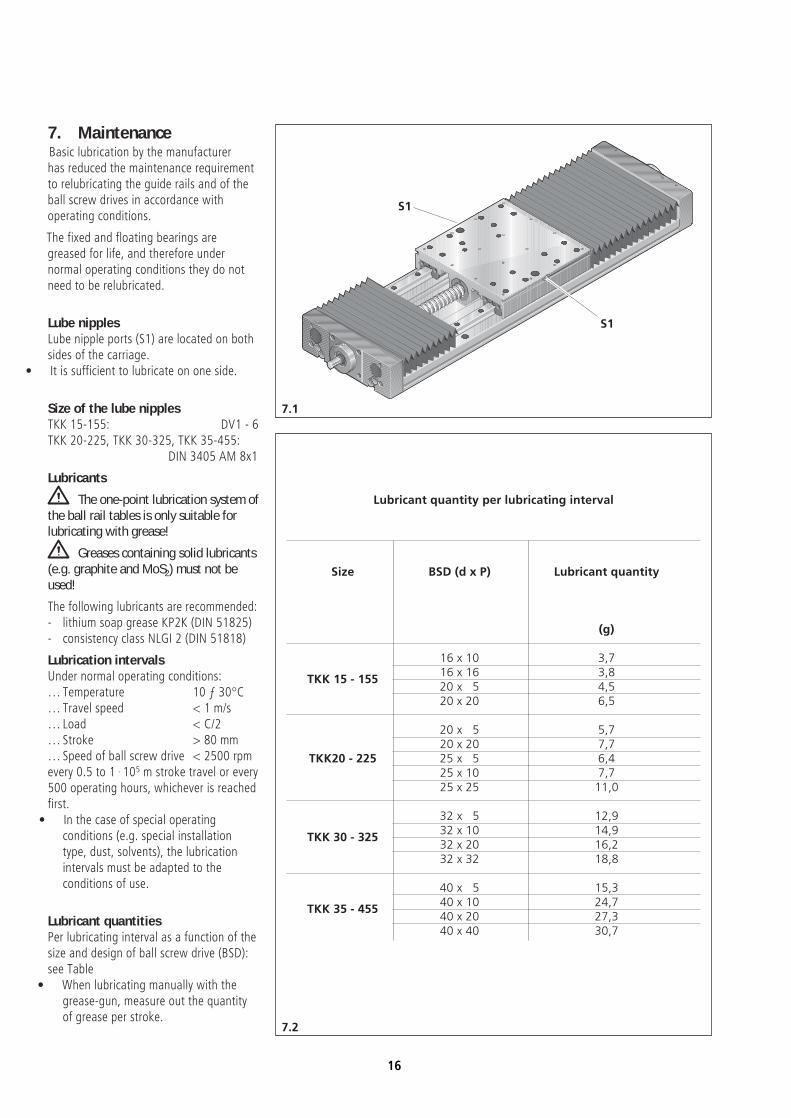
Lubricant quantity per lubricating interval
Size BSD (d x P) Lubricant quantity
(g)
16 x 10 3,716 x 16 3,8TKK 15 - 15520 x 5 4,520 x 20 6,5
20 x 5 5,720 x 20 7,7
TKK20 - 225 25 x 5 6,425 x 10 7,725 x 25 11,0
32 x 5 12,932 x 10 14,9TKK 30 - 32532 x 20 16,232 x 32 18,8
40 x 5 15,340 x 10 24,7TKK 35 - 45540 x 20 27,340 x 40 30,7
S1
S1
7. MaintenanceBasic lubrication by the manufacturerhas reduced the maintenance requirementto relubricating the guide rails and of theball screw drives in accordance withoperating conditions.
The fixed and floating bearings aregreased for life, and therefore undernormal operating conditions they do notneed to be relubricated.
Lube nipplesLube nipple ports (S1) are located on bothsides of the carriage.
• It is sufficient to lubricate on one side.
Size of the lube nipplesTKK 15-155: DV1 - 6TKK 20-225, TKK 30-325, TKK 35-455:
DIN 3405 AM 8x1
LubricantsThe one-point lubrication system of
the ball rail tables is only suitable forlubricating with grease!
Greases containing solid lubricants(e.g. graphite and MoS2) must not beused!The following lubricants are recommended:- lithium soap grease KP2K (DIN 51825)- consistency class NLGI 2 (DIN 51818)
Lubrication intervalsUnder normal operating conditions:… Temperature 10 ƒ 30°C… Travel speed < 1 m/s… Load < C/2… Stroke > 80 mm… Speed of ball screw drive < 2500 rpmevery 0.5 to 1 . 105 m stroke travel or every500 operating hours, whichever is reachedfirst.
• In the case of special operatingconditions (e.g. special installationtype, dust, solvents), the lubricationintervals must be adapted to theconditions of use.
Lubricant quantitiesPer lubricating interval as a function of thesize and design of ball screw drive (BSD):see Table
• When lubricating manually with thegrease-gun, measure out the quantityof grease per stroke.
16
8.1
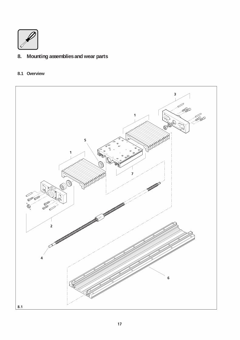
8. Mounting assemblies and wear parts
8.1 Overview
STAR
STAR
STAR
STAR
STARDeutsche Star Gmbh
D-97419 Schweinfurt
Tel. 09721/9370 - Fax 937275
TKK 20-22552278/3
07.07.1995
TYPID - NrDatum
STAR - matic
1
1
2
3
4
5
6
7
17
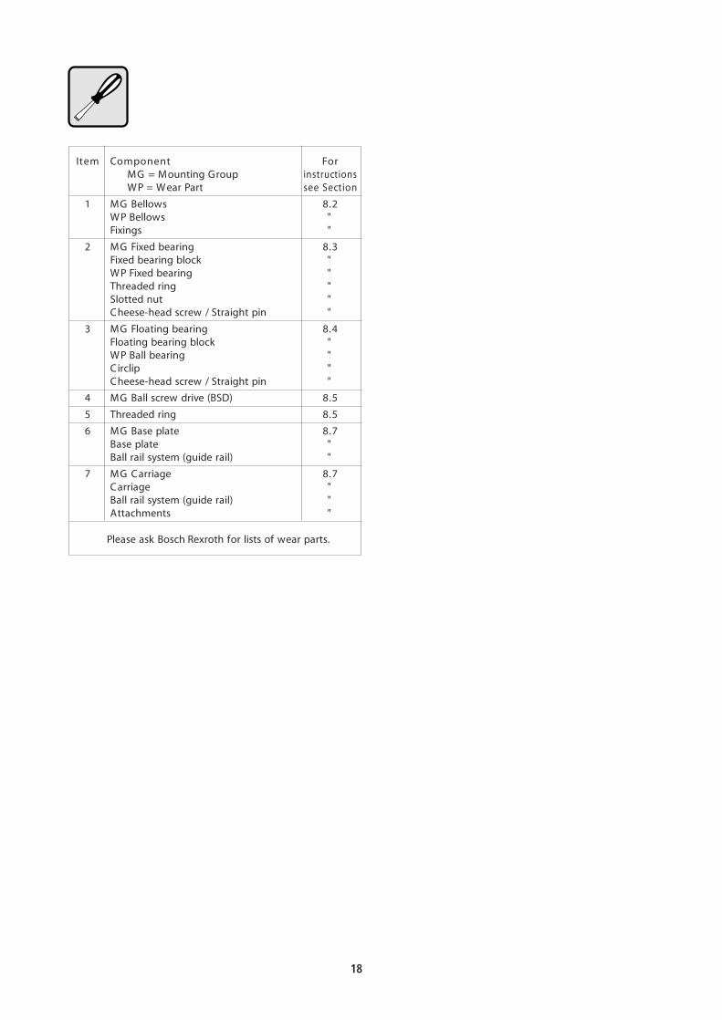
Item Component ForMG = Mounting Group instructionsWP = Wear Part see Section
1 MG Bellows 8.2WP Bellows "Fixings "
2 MG Fixed bearing 8.3Fixed bearing block "WP Fixed bearing "Threaded ring "Slotted nut "Cheese-head screw / Straight pin "
3 MG Floating bearing 8.4Floating bearing block "WP Ball bearing "Circlip "Cheese-head screw / Straight pin "
4 MG Ball screw drive (BSD) 8.5
5 Threaded ring 8.5
6 MG Base plate 8.7Base plate "Ball rail system (guide rail) "
7 MG Carriage 8.7Carriage "Ball rail system (guide rail) "Attachments "
Please ask Bosch Rexroth for lists of wear parts.
18

8.2.3
8.2.1
8.2.2
STAR
STAR
STAR
STAR
STAR
STAR
STAR
STAR
STAR
STAR
STAR
STAR
1
2
3
4
8.2 Dismantling/mountingbellows
Dismantling the bellows:Disconnect from mains before
dismantling!• For ball rail tables with timing belt side
drives, remove the covers of the sidedrive.! 6.5
• Unscrew the bellows from the bearingblock (1).
• Remove the inner frame (2).
Do not tear the bellows!• Pull the bellows up to the carriage. If
necessary, grip from underneath withthe other hand.
• Unscrew the bellows from the carriage (3).
• Remove the other inner frame.
Mounting the bellows• Fit the inner frame (4) in the first or last
fold so that one stiffening rib of thebellows is clamped with the frame.
• Screw the bellows to the carriage (3).• Tightening torque for M4 screws:
2 Nm. For M5: 3.8 Nm.• Insert the bellows at the fixed or
floating bearing end.• Hold the inner frame (2) firmly against
the bearing block and screw to thebearing block (2). Tightening torque forM4 screws: 2 Nm. For M5: 3.8 Nm.
19

8.3.2
8.3.1
8.3.3
STAR
STAR
STAR
STAR
STAR
STAR
STAR
STAR
Use plastic jaws!
Use plastic jaws!
2
3
4
5
1
8.3 Replacing the fixed bearing
Removing the bearing block togetherwith the fixed bearing
If the ball rail table is installedvertically or at an inclined angle, thecarriage must be prevented crashingdown!• Move the carriage to its mid-position.
Remove the motor. ! 6.3 or 6.5• Dismantle the bellows. ! 8.2
If a plug is plugged into the bearingblock, disconnect it from the socket.
• Loosen the socket locating set screw (1).• Unscrew the set screws (2) in the
slotted nut.• Clamp the BSD screw in position. .
Use plastic jaws!!• Unscrew the slotted nut (3).
Remove the internally threaded straightpins (4).
• Unscrew the cheese-head screws (5).• Remove the bearing block and fixed
bearing carefully from the screw of theBSD, keeping them perfectly straight.
Removing the fixed bearing (angularcontact ball bearing) from thebearing block
Fit plastic jaws to the vice.Clamp the bearing block in the vice.
The screwed ring is fixed with Loctite 638.
• Heat the screwed ring with a hot airblower until the adhesive starts to runand the screwed ring can be loosened.
• Unscrew and remove the screwed ringwith a ring wrench.
• Lay the bearing block flat on a supportwith a recess under the fixed bearing.Carefully push out the fixed bearing.
20
8.3.6
8.3.4
8.3.5
Loctite
STAR
STAR
Use plastic jaws!
STAR
STAR
STAR
STAR
12
3
4
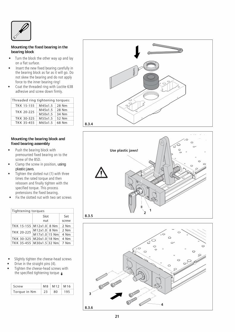
Mounting the fixed bearing in thebearing block
• Turn the block the other way up and layon a flat surface.
• Insert the new fixed bearing carefully inthe bearing block as far as it will go. Donot skew the bearing and do not applyforce to the inner bearing ring!
• Coat the threaded ring with Loctite 638adhesive and screw down firmly.
Threaded ring tightening torques:
TK K 15-155 M45x1.5 28 NmM45x1.5 28 Nm
TK K 20-225M50x1.5 34 Nm
TK K 30-325 M55x1.5 52 NmTK K 35-455 M65x1.5 68 Nm
Mounting the bearing block andfixed bearing assembly
• Push the bearing block withpremounted fixed bearing on to thescrew of the BSD.
• Clamp the screw in position, usingplastic jaws.
• Tighten the slotted nut (1) with threetimes the rated torque and thenreloosen and finally tighten with thespecified torque. This processpretensions the fixed bearing.
• Fix the slotted nut with two set screws
Tightening torques
Slot Setnut screw
TK K 15-155 M12x1.0 8 Nm 2 NmM12x1.0 8 Nm 2 Nm
TK K 20-225M17x1.0 15 Nm 4 Nm
TK K 30-325 M20x1.0 18 Nm 4 NmTK K 35-455 M30x1.5 32 Nm 7 Nm
• Slightly tighten the cheese-head screws• Drive in the straight pins (4).• Tighten the cheese-head screws with
the specified tightening torque /
Screw M 8 M 12 M 16
Torque in Nm 23 80 195
21

8.4.3
8.4.2
8.4.1
STAR
STAR
STAR
STAR
STAR
STAR
STAR
STAR
1
32
Screw M 8 M 12 M 16
Torque in Nm 23 80 195
Mounting the floating bearingsDo not oil the bearings and the end
of the screw! Otherwise the bearingsmay slip in operation!• Push both floating bearings on to the
end of the screw and secure withcirclips.
• Carefully push the bearing block overthe floating bearings.
• Slightly tighten the cheese-head screws.• Drive in the straight pins.• Tighten the cheese-head screws with
tightening torque / .
8.4 Replacing the floatingbearing
Removing the floating bearing• If necessary, dismantle the motor and
timing belt side drive. ! 6.5• Remove the bellows at the floating
bearing end. ! 8.2• If a socket and plug is mounted in the
bearing block, remove the plug fromthe socket. Loosen the socket locatingset screw (1).
• Move the carriage to about 20 mmfrom the floating bearing.
• Remove the internally threaded straightpins (2).
• Unscrew the cheese-head screws (3).
• Carefully remove the floating bearingblock. The bearings remain on the endof the screw. If fitted, the socketremains on the ball rail table.
• Remove the circlips.• Pull the two bearings off the screw.
22

8.5.3
8.5.1
8.5.2
STAR
STAR
STAR
STAR
STAR
STAR
STAR
STAR
STAR
STAR
STAR
STAR
$
8.5 Replacing the ball screwdrive (BSD)
Dismantling the BSDDisconnect from the mains before
dismantling!If the ball rail table is installed
vertically or at an inclined angle, thecarriage must be prevented fromcrashing down!
The BSD may only be replacedcomplete with the nut. If the nut isremoved from the screw, balls will belost, causing the destruction of the BSD ifthe nut is remounted.
• Remove the motor complete with motormount. ! 6.3 or 6.5
• Remove the bellows. ! 8.2• Remove the fixed bearing block and
fixed bearing. ! 8.3• Remove the floating bearing block and
floating bearings. ! 8.4
The screwed ring is fixed with Loctite 638.
• Heat the screwed ring with a hot airblower until the adhesive starts to runand the screwed ring can be loosened.
• Unscrew and remove the screwed ringwith a ring wrench.
• Prepare V-shaped supports for thescrew with a recess for the nut.
• Carefully pull the screw, complete withnut, out of the carriage.
• Lay the screw on the V-shapedsupports.
Do not rest the screw on the nut!Significant bending of the screw
indicates a danger of permanentdeformation!
Longer screws (1500 mm andmore) should be supported or suspendedat several support points.
23
8.5.5
8.5.4
8.6 8.7
STAR
STAR
STAR
STAR
STAR
STAR
Loctite
12
3
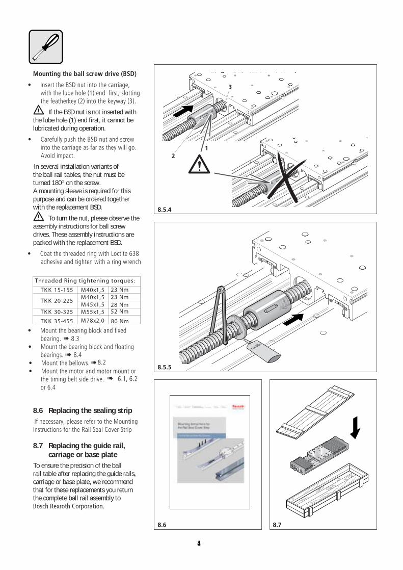
Mounting the ball screw drive (BSD)
• Insert the BSD nut into the carriage,with the lube hole (1) end first, slottingthe featherkey (2) into the keyway (3).
If the BSD nut is not inserted withthe lube hole (1) end first, it cannot belubricated during operation.
• Carefully push the BSD nut and screwinto the carriage as far as they will go.Avoid impact.
In several installation variants ofthe ball rail tables, the nut must beturned 180° on the screw.A mounting sleeve is required for thispurpose and can be ordered togetherwith the replacement BSD.
To turn the nut, please observe theassembly instructions for ball screwdrives. These assembly instructions arepacked with the replacement BSD.
• Coat the threaded ring with Loctite 638adhesive and tighten with a ring wrench
Threaded Ring tightening torques:
TK K 15-155 M40x1,5 23 NmM40x1,5 23 Nm
TK K 20-225M45x1,5 28 Nm
TK K 30-325 M55x1,5 52 Nm
TK K 35-455 M78x2,0 80 Nm
• Mount the bearing block and fixedbearing.! 8.3
• Mount the bearing block and floatingbearings.! 8.4
• Mount the bellows.
!
8.2
• Mount the motor and motor mount orthe timing belt side drive.
!
6.1, 6.2
or 6.4
8.6 Replacing the sealing stripIf necessary, please refer to the MountingInstructions for the Rail Seal Cover Strip
8.7 Replacing the guide rail,carriage or base plate
To ensure the precision of the ballrail table after replacing the guide rails,carriage or base plate, we recommendthat for these replacements you returnthe complete ball rail assembly toBosch Rexroth Corporation.
24

9.1.3
9.1.1
9.1.2
X-axis
Y-axis
STAR
STAR
STAR
STAR
1
3
4
5
67
8
9
2
3
3
3
Cross-plate
2
6
4
9
9. Mounting X-Y tables
9.1 Mounting two ball rail tablesof the same size (base plateon carriage)
The attachments on X-Y tablesmust be mounted with care to ensurethey cannot be damaged!
Note the desired direction ofinstallation.! 9.1.1
• Fix the cross-plate to the X-axiscarriage with screws (1) and pins (2).
• Insert the straight pins (3) for locatingthe Y-axis base plate.
• Insert and position four pairs of T-nuts(4) in the T-slots of the Y-axis base plate.
• Place the Y-axis table on the cross-plateand lay it with the reference edge of thebase plate (5) on the locating pins (3).
• Fix the cross-plate from underneath tothe Y-axis base plate or to the ready-positioned T-nuts using screws (6).
• Move the Y-axis carriage away from thecross-plate zone by turning the BSD (7).
• Remove the Y-axis bellows covering thecross-plate zone. ! 8.2
• Fix the Y-axis base plate to the cross-plate from above with screws (8) in thecorresponding threaded cross-plate holes.
• Drill holes in the Y-plate base platefrom underneath through the pre-drilled pin holes in the cross-plate(transfer the drill-hole pattern of thecross-plate to the base plate), deburrand fix with pins (9).
25

9.2.3
9.2.1
9.2.2
X-axis
Y-axis
Cross-plate
STAR
STAR
STAR
STAR
1
2
3
4
5
6
7
8
9
1
2
47
8
9
9.2 Mounting a ball rail table ofthe next smaller size (baseplate on carriage)
The attachments on X-Y tablesmust be mounted with care to ensurethey cannot be damaged!
• Drive straight pins (1) into the cross-plate for locating the Y-axis base plate.
• Insert and position four pairs of T-nuts(2) in the T-slots of the Y-axis base plate.
• Place the Y-axis table on the cross-plateand lay it with the reference edge ofthe base plate (3) on the locating pins (1).
• Fix the cross-plate from underneath tothe Y-axis base plate or to the ready-positioned T-nuts using screws (4).
• Move the Y-axis carriage away from thecross-plate zone by turning the BSD (5).
• Remove the Y-axis bellows covering thecross-plate zone. ! 8.2
• Fix the Y-axis base plate from above tothe cross-plate with screws (6) in thecorresponding threaded cross-plate holes.
• Drill holes in the Y-plate base platefrom underneath through the pre-drilled pin holes in the cross-plate(transfer the drill-hole pattern of thecross-plate to the base plate), deburrand fix with pins (7).
• Note the desired direction ofinstallation.! 9.2.1
• Place the Y-axis table with mountedcross-plate on the carriage of theX-axis table.
• Fix the cross-plate from above to theX-axis carriage with screws (8) and pins (9).
26

9.3.2
9.3.1
9.3.3
X-axis
Y-axis
Cross-plate
9.3 Mounting two ball rail tablesof the same size (carriage tocarriage)
The attachments on X-Y tablesmust be mounted with care to ensurethey cannot be damaged!
• Note the desired direction ofinstallation.! 9.3.1
• Screw and pin the cross-plate to theX-axis carriage.
• Place the Y-axis ball rail table upsidedown on the cross-plate.
• Screw and pin the cross-plate fromunderneath to the Y-axis carriage.
27
9.4.3
9.4.1
9.4.2
X-axis
Y-axis
Cross-plate
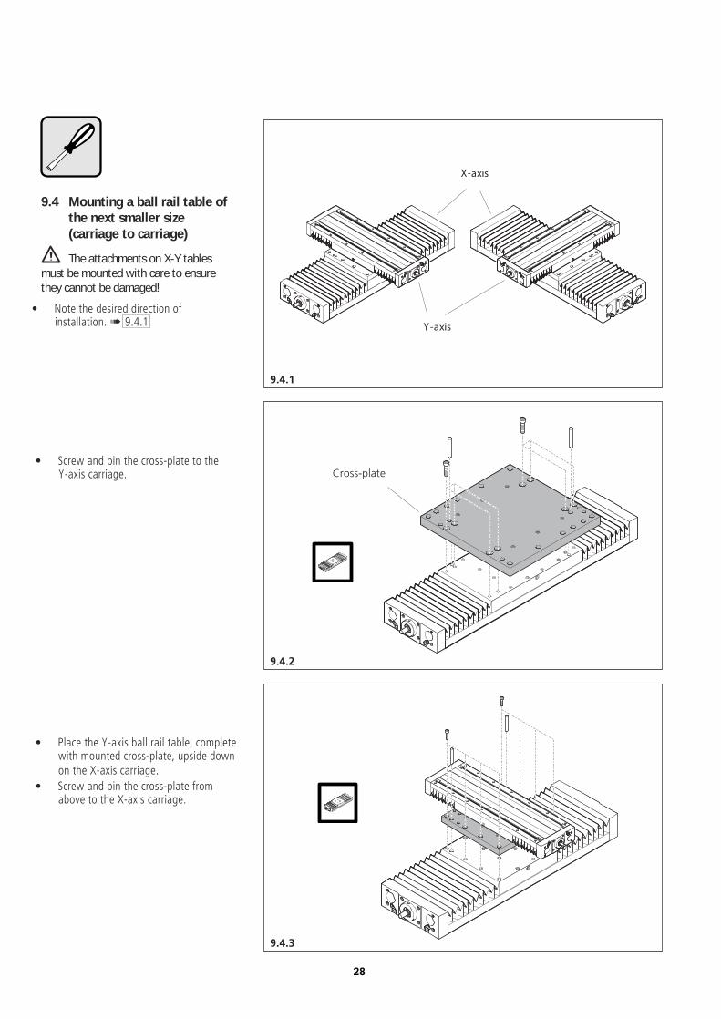
9.4 Mounting a ball rail table ofthe next smaller size(carriage to carriage)
The attachments on X-Y tablesmust be mounted with care to ensurethey cannot be damaged!
• Note the desired direction ofinstallation.! 9.4.1
• Screw and pin the cross-plate to theY-axis carriage.
• Place the Y-axis ball rail table, completewith mounted cross-plate, upside downon the X-axis carriage.
• Screw and pin the cross-plate fromabove to the X-axis carriage.
28

Bosch Rexroth CorporationCorporate Headquarters5150 Prairie Stone ParkwayHoffman Estates, IL 60192-3707Telephone (847) 645-3600Facsimile (847) 645-6201
Bosch Rexroth CorporationIndustrial Hydraulics2315 City Line RoadBethlehem, PA 18017-2131Telephone (610) 694-8300Facsimile (610) 694-8467
Bosch Rexroth CorporationElectric Drives and Controls5150 Prairie Stone ParkwayHoffman Estates, IL 60192-3707Telephone (847) 645-3600Facsimile (847) 645-6201
Bosch Rexroth CorporationPneumatics1953 Mercer RoadLexington, KY 40511-1021Telephone (859) 254-8031Facsimile (859) 281-3491
Bosch Rexroth CorporationMobile Hydraulics1700 Old Mansfield RoadWooster, OH 44691-0394Telephone (330) 263-3300Facsimile (330) 263-3333
RE 82 751
Bosch Rexroth CorporationLinear Motion andAssembly Technologies14001 South Lakes DriveCharlotte, NC 28273Telephone (800) 438-5983Facsimile (704) 583-0523www.boschrexroth-us.com

![EXPO RAIL OPERATIONS AND MAINTENANCE · PDF file01 78 43 SPARE PARTS AND REPLACEMENT MATERIALS [EXPO] ... Expo Rail Operations and Maintenance Facility TABLE OF](https://cdn.vdocument.in/doc/165x107/5a8091c47f8b9a0c748c7b20/expo-rail-operations-and-maintenance-78-43-spare-parts-and-replacement-materials.jpg)


