
Bearing specification tables

Standard bearings
Deep groove ball bearings .......... B 4
Single-row
Open type ........................................ B 8
Shielded/sealed type ...................... B 20
Snap ring groove/locating snap ring type ................... B 32
Extra-small, miniature ball bearings
Open/shielded/sealed type .............. B 38
Flanged type (open/shielded type) ... B 44
Double-row ......................................... B 50
Angular contact ball bearings .... B 52
Single-row .......................................... B 60
Matched pair ...................................... B 88
Double-row ....................................... B 116
Self-aligning ball bearings ........ B 122
Open type ......................................... B 124
Sealed type ...................................... B 130
Extended inner ring type .................. B 132
Adapter assemblies for self-aligning ball bearings ... B 134
Cylindrical roller bearings ......... B 136
Single-row ........................................ B 140
Thrust collars .................................... B 166
Double-row ....................................... B 176
Tapered roller bearings .............. B 182
Single-row
Metric series ................................. B 186
Inch series .................................... B 216
Double-row
TDO type ...................................... B 260
TDI type ......................................... B 276
Contents
Spherical roller bearings ........... B 282
Spherical roller bearings .................. B 286
Adapter assemblies for spherical roller bearings .............. B 310
Withdrawal sleeves for spherical roller bearings .............. B 318
Thrust ball bearings ..................... B 328
Single direction ................................. B 330
Double direction ............................... B 340
Spherical thrust roller bearings ..... B 346
Needle roller bearings ................. B 354
Needle roller and cage assemblies ... B 372
Drawn cup type ................................ B 406
Heavy-duty type ............................... B 424
Thrust ............................................... B 436
Combined ......................................... B 452
Inner ring .......................................... B 458
(Miniature one-way clutches) ........... B 474
[Introduction]Ball bearing units .......................... B 478
Special purpose bearings
K-series super thin section
ball bearings ..................................... C 1
Deep groove type
Angular contact type ................... C 9
Four-point contact type
Sealed type ........................................ C 19
Bearings for railway
rolling stock axle journals ........... C 21
Cylindrical roller bearings ................... C 25
Sealed type cylindrical roller bearings ..... C 27
Sealed type tapered roller bearings
(ABU bearing) .................................... C 29
Linear ball bearings ....................... C 31
Linear ball bearings ............................ C 35
Flanged type ...................................... C 41
Accessories ...................................... C 45
Locknuts ............................................. C 47
Lockwashers ...................................... C 53
Lock plates ......................................... C 55
[Introduction]Ceramic & bearing series ..... C 57
Bearings for machine tool spindles
(for support of axial loading) ...... C 59
Precision ball screw support bearings
and bearing units ............................... C 61
Full complement type cylindrical roller
bearings for crane sheaves ................... C 63
Rolling mill roll neck bearings ... C 65

B 4 B 5
Deep groove ball bearings Single-row deep groove ball bearings
Extra-small ball bearings andminiature ball bearings
Double-row deep groove ball bearings
Open type
Bore diameter 10 – 500 mm
Shielded/sealed type
Flanged type
(with filling slot)
With snap ring groove With locating snap ring
Bore diameter 10 – 220 mm
Bore diameter 10 – 130 mm
Bore diameter 1 – 9 mm
Bore diameter 1 – 9 mm
Bore diameter 10 – 75 mm
Deep groove ball bearings are available in a variety of sizes, and are the most popular of all rolling bearings. This type of bearing supports radial load and a certain degree of axial load in both directions simultaneously.
■ Shielded / sealed type*Simplifies sealing structure of applications.*Greasing is not necessary because bearings are
pre-lubricated.*Table 1 on the next page lists major shielded and sealed
bearing types and compares their performance.
■ With locating snap ring*Bearings with a locating snap ring can be fit to the
housing easily, as the locating snap ring facilitates axial positioning.
■ Extra-small ball bearings and miniature ball bearings*The open type is widely used. Also available are the
shielded/sealed type and the flanged type; the latter is easily positioned in the axial direction.

B 6 B 7
Table 1 Comparison of shielded and sealed bearing performance
Type
Character-istics
Shielded Sealed
Non-contact type Non-contact type Contact type Extremely light contact type
ZZ type 2RU type 2RS type 2RK type 2RD type
(a) 1) (b) (c) (d) 2) (e) (f) (g)
Friction torque Small Small Large Large Small
High speed performance Good Good Limited because of contact Good
Grease sealing property Good Better than
ZZ typeBetter than 2RU type for low-speed applications Excellent Excellent
Dirt resistance Good Better than ZZ type
Better than 2RU type Excellent Excellent
Water resistance EconomicalBetter than ZZ type but inferior to 2RS, 2RK and 2RD types
Good Excellent Better than ZZ and 2RU types
Operating temperature 3) − 30 to +110°C − 30 to +100°C − 30 to +110°C
[Notes] 1) Illustration (a) of the ZZ type shows the relatively small size bearing. 2) Illustration (d) of the 2RS type shows the relatively small size bearing. 3) The operating temperature range listed is for the standard type. It can be widened by using a different
type of grease or sealing material. Consult with JTEKT for details.
■ Handling instructions1) The shielded/sealed type deep groove ball bearing and the deep groove ball bearing with a locating
snap ring are designed for use with the inner ring rotating. Consult with JTEKT on use with the outer ring rotating.2) When the axial load is large, make the shaft shoulder and housing shoulder larger than usual.
(Referring to the specification table, make the mounting dimension da larger and make Da smaller.)
Boundary dimensions The dimensions of standard series are as specified in JIS B 1512.For extra-small and miniature ball bearings, special series (ML) are specified together with those described above.
Tolerances As specified in JIS B 1514-1. (refer to Table 7-3 on pp. A 60 − A 63.)
Radial internal clearance ■ Deep groove ball bearings (except extra-small ball bearings and miniature ball bearings) ...................... as specified in JIS B 1520 (refer to Table 10-2 on p. A 102.)
■ Extra-small ball bearings and miniature ball bearings ........... (refer to Table 10-3 on p. A 102.)■ Deep groove ball bearings for motors .................... (refer to Table 10-6 on p. A 105.)
Recommended fits ■ Bearings of classes 0 and 6 .............................. (refer to Table 9-4 on pp. A 91, 92.)■ Precision extra-small ball bearings and miniature ball bearings ........... (refer to Table 9-5 on p. A 93.)
Standard cages * Polyamide molded cage (supplementary code : FG, MG )
* Pressed steel cage (supplementary code : // )
* Copper alloy machined cage (supplementary code : FY )
[Remark]For certain applications, stainless steel sheet pressed cages (YS) may also be used.
Application of standard cages
Bearing series Molded cage Pressed cage Machined cage
6869606263
683 − 689693 − 699603 − 609623 − 629633 − 639
−−−−−
−−−−−
6869
16060626364
−−−
6000 − 60096200 − 62086300 − 6306
−
6800 − 68386900 − 6918
16001 − 160286010 − 60346209 − 62306307 − 63286403 − 6418
6840 − 68/6006920 − 6980
16030 − 160726036 − 60846232 − 62486330 − 6340
−
4243
−−
4200 − 42154302 − 4315
−−
Allowable misalignment 0.002 3 − 0.003 4 rad ( 8’ − 12’ )
Equivalent radial load (Single/double-row)
Dynamic equivalent radial load
Pr = XFr + YFa
refer to the table on the right for values X and Y.
Static equivalent radial load
P0r = 0.6Fr + 0.5Fa
when the value ofP0r < Fr, P0r = Fr
0.190.220.26
0.280.300.34
0.380.420.44
1
0
0.56
2.301.991.71
1.551.451.31
1.151.041.00
YXYXe
FaFr
² e FaFr
> e
0.1720.3450.689
1.031.382.07
3.455.176.89
if0Fa
C0r
Factor f0 is shown in the bearing dimension table.

open typeSingle-row deep groove ball bearings
ra
u Da u da
Br
r
u D u d
ra
Boundary dimensions Basic load ratings Fatigue
Factor
Limiting speeds
Bearing No.
Mounting dimensions
(Refer.)
Mass
(kg)
(mm) (kN)
load limit
(min
−
1
) (mm)
d D Br
C
r
C
0r
(kN)
f
0
Greaselub.
Oil lub.
d
a
D
a
r
a
min.
C
u
min. max. max.
10
19 5 0.3 2.15 0.84 0.030 14.8 37 000 43 000
6800
12 17 0.3 0.005
10
22 6 0.3 3.35 1.25 0.070 14.0 34 000 41 000
6900
12 20 0.3 0.010
10
26 8 0.3 5.70 1.95 0.100 12.3 31 000 36 000
6000
12 24 0.3 0.019
10
30 9 0.6 6.40 2.40 0.120 13.2 24 000 29 000
6200
14 26 0.6 0.032
10
35 11 0.6 10.1 3.45 0.270 11.2 22 000 27 000
6300
14 31 0.6 0.053
12
21 5 0.3 2.40 1.05 0.040 15.3 33 000 39 000
6801
14 19 0.3 0.006
12
24 6 0.3 3.60 1.45 0.080 14.5 31 000 36 000
6901
14 22 0.3 0.011
12
28 7 0.3 6.40 2.40 0.120 13.2 27 000 32 000
16001
14 26 0.3 0.024
12
28 8 0.3 6.40 2.40 0.120 13.2 27 000 32 000
6001
14 26 0.3 0.022
12
32 10 0.6 8.50 3.05 0.240 12.3 22 000 27 000
6201
16 28 0.6 0.037
12
37 12 1 12.1 4.20 0.420 11.1 20 000 25 000
6301
17 32 1 0.060
15
24 5 0.3 2.60 1.25 0.050 15.8 28 000 33 000
6802
17 22 0.3 0.007
15
28 7 0.3 5.40 2.25 0.120 14.3 26 000 30 000
6902
17 26 0.3 0.017
15
32 8 0.3 7.00 2.85 0.150 13.9 23 000 28 000
16002
17 30 0.3 0.025
15
32 9 0.3 7.00 2.85 0.150 13.9 23 000 27 000
6002
17 30 0.3 0.030
15
35 11 0.6 9.55 3.75 0.290 13.2 20 000 24 000
6202
19 31 0.6 0.045
15
42 13 1 14.3 5.45 0.460 12.3 17 000 20 000
6302
20 37 1 0.082
17
26 5 0.3 3.30 1.55 0.060 15.7 26 000 30 000
6803
19 24 0.3 0.008
17
30 7 0.3 5.75 2.55 0.130 14.7 23 000 28 000
6903
19 28 0.3 0.018
17
35 8 0.3 7.50 3.25 0.170 14.4 21 000 25 000
16003
19 33 0.3 0.032
17
35 10 0.3 7.50 3.25 0.170 14.4 21 000 25 000
6003
19 33 0.3 0.039
17
40 12 0.6 12.0 4.80 0.370 13.2 17 000 21 000
6203
21 36 0.6 0.065
17
47 14 1 17.0 6.65 0.550 12.4 15 000 18 000
6303
22 42 1 0.115
17
47 14 1 19.6 7.60 0.680 12.0 15 000 18 000
6303R
22 42 1 0.121
17
62 17 1.1 25.9 9.85 0.920 11.6 13 000 15 000
6403
23.5 55.5 1 0.270
20
32 7 0.3 5.00 2.45 0.100 15.5 21 000 25 000
6804
22 30 0.3 0.018
20
37 9 0.3 7.95 3.70 0.190 14.7 19 000 23 000
6904
22 35 0.3 0.036
20
42 8 0.3 9.90 4.50 0.290 14.4 17 000 21 000
16004
22 40 0.3 0.050
[Remark] Standard cage types used for the above bearings are described earlier in this section.
20
42 12 0.6 11.7 5.05 0.350 13.9 17 000 21 000
6004
24 38 0.6 0.069
20
42 12 0.6 14.4 5.85 0.460 13.0 18 000 21 000
6004R
24 38 0.6 0.073
20
47 14 1 16.0 6.65 0.510 13.2 15 000 17 000
6204
25 42 1 0.106
20
47 14 1 19.6 7.60 0.680 12.0 15 000 18 000
6204R
25 42 1 0.114
20
52 15 1.1 19.9 7.85 0.660 12.3 14 000 17 000
6304
26.5 45.5 1 0.144
20
52 15 1.1 22.6 8.95 0.790 12.0 14 000 16 000
6304R
26.5 45.5 1 0.151
20
72 19 1.1 38.7 15.2 1.50 11.1 11 000 13 000
6404
26.5 65.5 1 0.400
22
44 12 0.6 11.7 5.15 0.350 14.1 17 000 20 000
60/22
26 40 0.6 0.073
22
50 14 1 16.0 6.65 0.510 13.2 15 000 17 000
62/22
27 45 1 0.118
22
56 16 1.1 23.1 9.40 0.770 12.6 13 000 15 000
63/22
28.5 49.5 1 0.201
25
37 7 0.3 5.40 2.95 0.120 16.0 18 000 21 000
6805
27 35 0.3 0.022
25
42 9 0.3 8.75 4.55 0.230 15.4 16 000 19 000
6905
27 40 0.3 0.041
25
47 8 0.3 11.1 5.60 0.340 15.1 15 000 18 000
16005
27 45 0.3 0.060
25
47 12 0.6 12.6 5.85 0.380 14.5 15 000 18 000
6005
29 43 0.6 0.080
25
52 15 1 17.5 7.85 0.550 13.9 13 000 15 000
6205
30 47 1 0.128
25
52 15 1 22.1 9.30 0.740 12.8 13 000 16 000
6205R
30 47 1 0.138
25
62 17 1.1 25.7 11.3 0.860 13.2 11 000 13 000
6305
31.5 55.5 1 0.232
25
62 17 1.1 32.7 13.4 1.20 11.9 11 000 14 000
6305R
31.5 55.5 1 0.255
25
80 21 1.5 45.2 19.4 1.65 12.2 9 100 11 000
6405
33 72 1.5 0.530
28
52 12 0.6 15.6 7.40 0.480 14.5 14 000 16 000
60/28
32 48 0.6 0.097
28
58 16 1 22.4 9.75 0.720 13.4 12 000 14 000
62/28
33 53 1 0.173
28
68 18 1.1 29.4 13.1 0.990 13.3 10 000 12 000
63/28
34.5 61.5 1 0.328
30
42 7 0.3 5.65 3.40 0.140 16.4 15 000 18 000
6806
32 40 0.3 0.026
30
47 9 0.3 9.05 5.00 0.260 15.8 14 000 17 000
6906
32 45 0.3 0.045
30
55 9 0.3 14.1 7.35 0.440 15.2 13 000 15 000
16006
32 53 0.3 0.085
30
55 13 1 16.5 8.25 0.530 14.7 13 000 15 000
6006
35 50 1 0.116
30
62 16 1 24.3 11.3 0.800 13.9 11 000 13 000
6206
35 57 1 0.199
30
62 16 1 29.2 12.8 1.00 13.0 11 000 13 000
6206R
35 57 1 0.212
Boundary dimensions Basic load ratings Fatigue
Factor
Limiting speeds
Bearing No.
Mounting dimensions
(Refer.)
Mass
(kg)
(mm) (kN)
load limit
(min
−
1
) (mm)
d D Br
C
r
C
0r
(kN)
f
0
Greaselub.
Oil lub.
d
a
D
a
r
a
min.
C
u
min. max. max.
[Remark] Standard cage types used for the above bearings are described earlier in this section.
B 8 B 9
d
10
∼
(
20
)
mm
d
(
20
)
∼
(
30
)
mm

open typeSingle-row deep groove ball bearings
ra
u Da u da
Br
r
u D u d
ra
30
72 19 1.1 33.3 15.0 1.15 13.3 9 600 12 000
6306
36.5 65.5 1 0.346
30
72 19 1.1 41.7 17.7 1.55 12.0 9 800 12 000
6306R
36.5 65.5 1 0.379
30
90 23 1.5 54.2 23.9 2.05 12.3 8 100 9 700
6406
38 82 1.5 0.735
32
58 13 1 18.8 9.15 0.600 14.5 12 000 14 000
60/32
37 53 1 0.127
32
65 17 1 29.4 13.1 0.990 13.3 10 000 12 000
62/32
37 60 1 0.228
32
75 20 1.1 37.6 16.2 1.30 12.7 9 300 11 000
63/32
38.5 68.5 1 0.437
35
47 7 0.3 5.95 3.85 0.160 16.5 13 000 16 000
6807
37 45 0.3 0.030
35
55 10 0.6 13.6 7.75 0.440 15.7 12 000 14 000
6907
39 51 0.6 0.073
35
62 9 0.3 15.3 8.85 0.500 15.7 11 000 13 000
16007
37 60 0.3 0.110
35
62 14 1 19.9 10.3 0.640 14.9 11 000 13 000
6007
40 58 1 0.155
35
72 17 1.1 32.1 15.4 1.10 13.9 9 200 11 000
6207
41.5 65.5 1 0.288
35
72 17 1.1 38.7 17.5 1.40 12.9 9 300 11 000
6207R
41.5 65.5 1 0.309
35
80 21 1.5 41.7 19.3 1.45 13.2 8 500 10 000
6307
43 72 1.5 0.457
35
80 21 1.5 50.0 21.7 1.90 12.1 8 700 10 000
6307R
43 72 1.5 0.494
35
100 25 1.5 68.8 31.0 2.65 12.2 7 200 8 600
6407
43 92 1.5 0.952
40
52 7 0.3 6.15 4.20 0.180 16.3 12 000 14 000
6808
42 50 0.3 0.033
40
62 12 0.6 17.1 9.95 0.570 15.6 11 000 13 000
6908
44 58 0.6 0.112
40
68 9 0.3 15.8 9.65 0.530 16.0 9 800 12 000
16008
42 66 0.3 0.125
40
68 15 1 20.9 11.5 0.690 15.2 10 000 12 000
6008
45 63 1 0.192
40
80 18 1.1 36.4 17.8 1.25 14.0 8 300 10 000
6208
46.5 73.5 1 0.366
40
90 23 1.5 50.9 24.0 1.85 13.2 7 700 9 200
6308
48 82 1.5 0.633
40
110 27 2 79.6 36.6 3.15 12.3 6 600 7 900
6408
49 101 2 1.23
45
58 7 0.3 7.75 5.40 0.230 16.3 11 000 13 000
6809
47 56 0.3 0.040
45 68 12 0.6 17.7 10.9 0.600 15.9 9 700 11 000 6909 49 64 0.6 0.13245 75 10 0.6 19.4 12.3 0.670 16.0 8 900 10 000 16009 49 71 0.6 0.170
45 75 16 1 26.2 15.1 0.900 15.3 9 200 11 000 6009 50 70 1 0.24545 85 19 1.1 40.9 20.3 1.40 14.0 7 700 9 200 6209 51.5 78.5 1 0.40745 100 25 1.5 61.1 29.5 2.25 13.3 6 800 8 100 6309 53 92 1.5 0.833
Boundary dimensions Basic load ratings Fatigue Factor Limiting speeds
Bearing No.
Mounting dimensions (Refer.)
Mass(kg)
(mm) (kN) load limit (min−1) (mm)
d D Br
Cr C0r(kN)
f 0Grease
lub.Oil lub.
da Da ramin. Cu min. max. max.
[Remark] Standard cage types used for the above bearings are described earlier in this section.
45 120 29 2 96.5 45.1 3.90 12.2 6 000 7 200 6409 54 111 2 1.53
50 65 7 0.3 8.20 6.10 0.260 16.1 9 600 11 000 6810 52 63 0.3 0.05250 72 12 0.6 18.2 11.7 0.640 16.1 9 000 11 000 6910 54 68 0.6 0.13350 80 10 0.6 20.0 13.3 0.710 16.2 8 200 9 700 16010 54 76 0.6 0.180
50 80 16 1 27.3 16.6 0.960 15.6 8 400 9 900 6010 55 75 1 0.26150 90 20 1.1 43.9 23.3 1.55 14.4 7 100 8 500 6210 56.5 83.5 1 0.46350 90 20 1.1 50.5 25.5 1.80 13.9 7 100 8 600 6210R 56.5 83.5 1 0.487
50 110 27 2 77.5 38.3 2.90 13.2 6 100 7 300 6310 59 101 2 1.0750 130 31 2.1 104 49.5 4.10 12.5 5 500 6 600 6410 61 119 2 1.88
55 72 9 0.3 11.0 8.10 0.420 16.2 8 700 10 000 6811 57 70 0.3 0.08355 80 13 1 20.8 14.1 0.760 16.2 8 100 9 600 6911 60 75 1 0.18555 90 11 0.6 24.2 16.3 0.880 16.2 7 400 8 800 16011 59 86 0.6 0.260
55 90 18 1.1 35.3 21.2 1.25 15.3 7 600 8 900 6011 61.5 83.5 1 0.38555 100 21 1.5 54.2 29.4 1.95 14.4 6 300 7 600 6211 63 92 1.5 0.60755 120 29 2 89.5 45.0 3.45 13.2 5 600 6 700 6311 64 111 2 1.37
55 140 33 2.1 126 62.3 5.35 12.2 5 000 6 000 6411 66 129 2 2.29
60 78 10 0.3 14.3 10.6 0.550 16.3 8 000 9 400 6812 62 76 0.3 0.10460 85 13 1 25.2 17.3 0.940 16.2 7 500 8 900 6912 65 80 1 0.19260 95 11 0.6 24.8 17.6 0.930 16.4 6 900 8 100 16012 64 91 0.6 0.280
60 95 18 1.1 36.8 23.2 1.35 15.6 7 100 8 400 6012 66.5 88.5 1 0.41560 110 22 1.5 65.6 36.2 2.40 14.4 5 700 6 900 6212 68 102 1.5 0.78360 130 31 2.1 102 52.2 3.95 13.2 5 200 6 200 6312 71 119 2 1.70
60 150 35 2.1 137 70.8 5.75 12.4 4 600 5 500 6412 71 139 2 2.77
65 85 10 0.6 14.9 11.5 0.590 16.2 7 300 8 600 6813 69 81 0.6 0.12665 90 13 1 21.7 16.1 0.830 16.6 7 100 8 400 6913 70 85 1 0.21165 100 11 0.6 21.4 16.0 0.830 16.5 6 600 7 800 16013 69 96 0.6 0.300
65 100 18 1.1 38.1 25.2 1.40 15.8 6 600 7 800 6013 71.5 93.5 1 0.435
Boundary dimensions Basic load ratings Fatigue Factor Limiting speeds
Bearing No.
Mounting dimensions (Refer.)
Mass(kg)
(mm) (kN) load limit (min−1) (mm)
d D Br
Cr C0r(kN)
f 0Grease
lub.Oil lub.
da Da ramin. Cu min. max. max.
[Remark] Standard cage types used for the above bearings are described earlier in this section.
B 10 B 11
d (30) ∼ (45) mm d (45) ∼ (65) mm

open typeSingle-row deep groove ball bearings
ra
u Da u da
Br
r
u D u d
ra
65 120 23 1.5 71.5 40.1 2.65 14.4 5 400 6 400 6213 73 112 1.5 0.99065 140 33 2.1 116 59.9 4.50 13.2 4 800 5 800 6313 76 129 2 2.0865 160 37 2.1 148 79.2 6.20 12.4 4 300 5 200 6413 76 149 2 3.30
70 90 10 0.6 15.1 11.9 0.620 16.1 6 800 8 100 6814 74 86 0.6 0.13470 100 16 1 29.7 21.2 1.10 16.3 6 400 7 600 6914 75 95 1 0.34270 110 13 0.6 37.6 25.6 1.40 16.0 6 100 7 200 16014 74 106 0.6 0.433
70 110 20 1.1 47.6 30.9 1.80 15.6 6 100 7 200 6014 76.5 103.5 1 0.60270 125 24 1.5 77.8 44.1 2.90 14.5 5 100 6 100 6214 78 117 1.5 1.0770 150 35 2.1 130 68.2 4.95 13.2 4 500 5 400 6314 81 139 2 2.52
70 180 42 3 181 104 10.2 12.2 3 900 4 600 6414 83 167 2.5 4.83
75 95 10 0.6 15.7 12.9 0.660 16.0 6 400 7 600 6815 79 91 0.6 0.14275 105 16 1 30.5 22.6 1.20 16.5 6 100 7 200 6915 80 100 1 0.36375 115 13 0.6 34.4 25.3 1.35 16.4 5 700 6 700 16015 79 111 0.6 0.457
75 115 20 1.1 49.4 33.5 1.90 15.8 5 700 6 800 6015 81.5 108.5 1 0.63875 130 25 1.5 84.3 48.3 3.10 14.5 4 800 5 800 6215 83 122 1.5 1.1875 160 37 2.1 142 77.2 5.40 13.2 4 200 5 000 6315 86 149 2 3.02
75 190 45 3 192 115 10.9 12.3 3 600 4 400 6415 88 177 2.5 5.87
80 100 10 0.6 15.9 13.3 0.690 16.0 6 100 7 200 6816 84 96 0.6 0.15080 110 16 1 31.2 24.0 1.25 16.6 5 700 6 800 6916 85 105 1 0.38280 125 14 0.6 39.7 29.7 1.50 16.4 5 200 6 100 16016 84 121 0.6 0.597
80 125 22 1.1 59.5 39.8 2.25 15.6 5 300 6 300 6016 86.5 118.5 1 0.85080 140 26 2 90.9 53.0 3.25 14.6 4 500 5 400 6216 89 131 2 1.4080 170 39 2.1 154 86.7 5.85 13.3 3 900 4 700 6316 91 159 2 3.59
80 200 48 3 205 125 11.5 12.3 3 400 4 100 6416 93 187 2.5 6.84
85 110 13 1 23.4 19.0 0.980 16.2 5 600 6 600 6817 90 105 1 0.26685 120 18 1.1 39.9 29.6 1.55 16.4 5 300 6 300 6917 91.5 113.5 1 0.53585 130 14 0.6 40.8 31.7 1.55 16.5 4 900 5 800 16017 89 126 0.6 0.626
Boundary dimensions Basic load ratings Fatigue Factor Limiting speeds
Bearing No.
Mounting dimensions (Refer.)
Mass(kg)
(mm) (kN) load limit (min−1) (mm)
d D Br
Cr C0r(kN)
f 0Grease
lub.Oil lub.
da Da ramin. Cu min. max. max.
[Remark] Standard cage types used for the above bearings are described earlier in this section.
85 130 22 1.1 61.8 43.1 2.35 15.8 5 000 5 900 6017 91.5 123.5 1 0.89085 150 28 2 105 61.9 3.70 14.5 4 200 5 000 6217 94 141 2 1.7985 180 41 3 166 96.8 6.35 13.3 3 700 4 400 6317 98 167 2.5 4.23
85 210 52 4 217 136 12.2 12.3 3 300 3 900 6417 101 194 3 8.07
90 115 13 1 23.8 19.7 1.00 16.1 5 300 6 300 6818 95 110 1 0.27990 125 18 1.1 41.0 31.6 1.60 16.5 5 100 6 000 6918 96.5 118.5 1 0.56590 140 16 1 49.9 37.0 1.85 16.3 4 700 5 600 16018 95 135 1 0.848
90 140 24 1.5 72.8 49.7 2.65 15.6 4 700 5 600 6018 98 132 1.5 1.1690 160 30 2 120 71.5 4.20 14.5 3 900 4 700 6218 99 151 2 2.1590 190 43 3 178 107 8.80 13.3 3 500 4 200 6318 103 177 2.5 4.91
90 225 54 4 230 149 12.7 12.5 3 100 3 700 6418 106 209 3 9.78
95 130 18 1.1 42.1 33.5 1.65 16.6 4 800 5 700 6919 101.5 123.5 1 0.70595 145 16 1 51.5 39.6 1.90 16.4 4 500 5 300 16019 100 140 1 0.88595 145 24 1.5 75.5 53.9 2.75 15.8 4 400 5 200 6019 103 137 1.5 1.21
95 170 32 2.1 136 81.9 4.65 14.4 3 700 4 400 6219 106 159 2 2.6295 200 45 3 191 119 9.45 13.3 3 300 4 000 6319 108 187 2.5 5.67
100 125 13 1 24.5 21.2 1.05 16.0 4 800 5 700 6820 105 120 1 0.309100 140 20 1.1 56.2 41.9 2.05 16.2 4 500 5 300 6920 106.5 133.5 1 0.960100 150 16 1 53.0 42.1 1.95 16.5 4 300 5 100 16020 105 145 1 0.910
100 150 24 1.5 75.2 54.2 2.70 15.9 4 300 5 100 6020 108 142 1.5 1.25100 180 34 2.1 153 93.1 5.15 14.4 3 500 4 200 6220 111 169 2 3.14100 215 47 3 216 141 10.9 13.2 3 000 3 600 6320 113 202 2.5 7.00
105 145 20 1.1 58.1 44.8 2.10 16.4 4 300 5 100 6921 111.5 138.5 1 1.00105 160 18 1 52.3 42.2 1.90 16.5 4 100 4 800 16021 110 155 1 1.20105 160 26 2 90.4 65.8 3.20 15.8 4 000 4 700 6021 114 151 2 1.59
105 190 36 2.1 166 105 5.70 14.4 3 300 3 900 6221 116 179 2 3.70105 225 49 3 230 153 11.7 13.2 2 900 3 500 6321 118 212 2.5 8.05
Boundary dimensions Basic load ratings Fatigue Factor Limiting speeds
Bearing No.
Mounting dimensions (Refer.)
Mass(kg)
(mm) (kN) load limit (min−1) (mm)
d D Br
Cr C0r(kN)
f 0Grease
lub.Oil lub.
da Da ramin. Cu min. max. max.
[Remark] Standard cage types used for the above bearings are described earlier in this section.
B 12 B 13
d (65) ∼ (85) mm d (85) ∼ 105 mm

open typeSingle-row deep groove ball bearings
ra
u Da u da
Br
r
u D u d
ra
110 140 16 1 35.1 30.7 1.40 16.1 4 300 5 100 6822 115 135 1 0.606110 150 20 1.1 59.9 47.8 2.20 16.4 4 100 4 900 6922 116.5 143.5 1 1.04110 170 19 1 71.8 56.7 2.55 16.3 3 800 4 500 16022 115 165 1 1.46
110 170 28 2 103 73.0 3.55 15.6 3 800 4 500 6022 119 161 2 1.96110 200 38 2.1 180 117 6.20 14.4 3 100 3 700 6222 121 189 2 4.36110 240 50 3 257 180 13.3 13.2 2 700 3 200 6322 123 227 2.5 9.54
120 150 16 1 36.2 33.0 1.45 16.0 4 000 4 700 6824 125 145 1 0.655120 165 22 1.1 71.6 56.9 2.50 16.4 3 800 4 400 6924 126.5 158.5 1 1.41120 180 19 1 79.0 63.3 2.75 16.4 3 600 4 200 16024 125 175 1 1.80
120 180 28 2 106 79.3 3.60 15.9 3 600 4 200 6024 129 171 2 2.07120 215 40 2.1 194 131 6.65 14.4 2 900 3 400 6224 131 204 2 5.15120 260 55 3 258 185 12.6 13.5 2 500 3 000 6324 133 247 2.5 12.5
130 165 18 1.1 46.1 41.2 1.75 16.1 3 600 4 300 6826 136.5 158.5 1 0.939130 180 24 1.5 86.9 67.4 3.00 16.3 3 400 4 100 6926 138 172 1.5 1.86130 200 22 1.1 89.1 74.8 3.05 11.2 3 000 3 600 16026 136.5 193.5 1 2.69
130 200 33 2 133 101 4.45 15.8 3 200 3 800 6026 139 191 2 3.16130 230 40 3 209 146 9.15 14.5 2 700 3 200 6226 143 217 2.5 5.82130 280 58 4 287 214 14.1 13.6 2 300 2 700 6326 146 264 3 15.1
140 175 18 1.1 47.8 44.4 1.85 16.0 3 400 4 000 6828 146.5 168.5 1 1.00140 190 24 1.5 89.1 74.8 3.05 16.5 3 200 3 800 6928 148 182 1.5 1.98140 210 22 1.1 82.2 71.1 2.80 16.5 2 900 3 400 16028 146.5 203.5 1 2.86
140 210 33 2 137 109 4.55 15.9 3 000 3 600 6028 149 201 2 3.55140 250 42 3 208 150 8.65 14.8 2 400 2 900 6228 153 237 2.5 7.45140 300 62 4 316 246 15.6 13.6 2 100 2 500 6328 156 284 3 19.4
150 190 20 1.1 59.7 54.9 2.20 16.1 3 100 3 700 6830 156.5 183.5 1 1.40150 210 28 2 117 94.3 3.75 16.2 2 900 3 400 6930 159 201 2 3.05150 225 24 1.1 114 99.3 3.70 16.6 2 700 3 100 16030 156.5 218.5 1 3.58
150 225 35 2.1 157 126 5.10 16.0 2 800 3 300 6030 161 214 2 4.22
Boundary dimensions Basic load ratings Fatigue Factor Limiting speeds
Bearing No.
Mounting dimensions (Refer.)
Mass(kg)
(mm) (kN) load limit (min−1) (mm)
d D Br
Cr C0r(kN)
f 0Grease
lub.Oil lub.
da Da ramin. Cu min. max. max.
[Remark] Standard cage types used for the above bearings are described earlier in this section.
150 270 45 3 220 168 9.05 15.1 2 200 2 700 6230 163 257 2.5 9.41150 320 65 4 343 284 16.6 13.9 1 900 2 300 6330 166 304 3 26.2
160 200 20 1.1 60.5 56.9 2.20 16.1 2 900 3 400 6832 166.5 193.5 1 1.45160 220 28 2 120 101 3.85 16.4 2 700 3 200 6932 169 211 2 3.20160 240 25 1.5 124 108 3.95 16.5 2 600 3 100 16032 168 232 1.5 4.25
160 240 38 2.1 171 135 5.30 15.9 2 600 3 000 6032 171 229 2 5.22160 290 48 3 231 186 9.45 15.4 2 100 2 500 6232 173 277 2.5 14.3160 340 68 4 347 286 16.4 13.9 1 800 2 200 6332 176 324 3 29.0
170 215 22 1.1 74.8 70.5 2.60 16.1 2 700 3 200 6834 176.5 208.5 1 1.90170 230 28 2 124 108 3.95 16.5 2 600 3 100 6934 179 221 2 3.35170 260 28 1.5 142 127 4.45 16.5 2 300 2 700 16034 178 252 1.5 5.75
170 260 42 2.1 201 161 6.20 15.8 2 400 2 800 6034 181 249 2 6.80170 310 52 4 265 223 11.1 15.3 1 900 2 300 6234 186 294 3 17.5170 360 72 4 408 355 20.5 13.6 1 700 2 000 6334 186 344 3 38.6
180 225 22 1.1 75.8 73.1 2.65 16.1 2 600 3 000 6836 186.5 218.5 1 2.00180 250 33 2 153 129 4.70 16.3 2 400 2 800 6936 189 241 2 4.90180 280 31 2 169 148 5.15 16.4 2 100 2 500 16036 189 271 2 7.55
180 280 46 2.1 227 194 7.15 15.8 2 200 2 600 6036 191 269 2 10.3180 320 52 4 284 241 12.0 15.1 1 800 2 200 6236 196 304 3 18.3180 380 75 4 443 407 22.1 13.9 1 600 1 900 6336 196 364 3 44.7
190 240 24 1.5 91.4 88.1 3.10 16.1 2 400 2 800 6838 198 232 1.5 2.60190 260 33 2 158 138 4.85 16.4 2 300 2 700 6938 199 251 2 5.20190 290 31 2 173 158 5.20 16.6 2 000 2 400 16038 199 281 2 7.85
190 290 46 2.1 235 201 7.35 15.8 2 100 2 500 6038 201 279 2 10.8190 340 55 4 319 281 13.7 15.0 1 700 2 000 6238 206 324 3 23.0190 400 78 5 443 415 21.3 14.1 1 500 1 800 6338 210 380 4 51.5
200 250 24 1.5 97.6 93.6 3.20 16.1 2 300 2 700 6840 208 242 1.5 2.70
Boundary dimensions Basic load ratings Fatigue Factor Limiting speeds
Bearing No.
Mounting dimensions (Refer.)
Mass(kg)
(mm) (kN) load limit (min−1) (mm)
d D Br
Cr C0r(kN)
f 0Grease
lub.Oil lub.
da Da ramin. Cu min. max. max.
[Remark] Standard cage types used for the above bearings are described earlier in this section.
B 14 B 15
d 110 ∼ (150) mm d (150) ∼ (200) mm

open typeSingle-row deep groove ball bearings
ra
u Da u da
Br
r
u D u d
ra
200 280 38 2.1 196 168 5.80 16.2 2 100 2 500 6940 211 269 2 7.30200 310 34 2 201 180 5.95 16.4 1 900 2 300 16040 209 301 2 10.1200 310 51 2.1 272 243 11.3 15.6 1 900 2 300 6040 211 299 2 14.0
200 360 58 4 336 311 14.4 15.2 1 600 1 900 6240 216 344 3 28.2200 420 80 5 513 506 25.5 14.0 1 300 1 600 6340 220 400 4 58.0
220 270 24 1.5 101 101 3.35 16.0 2 000 2 400 6844 228 262 1.5 3.00220 300 38 2.1 201 180 5.85 16.4 1 900 2 200 6944 231 289 2 7.90220 340 37 2.1 225 217 6.65 16.5 1 700 2 000 16044 231 329 2 13.2
220 340 56 3 294 271 12.0 15.6 1 700 2 000 6044 233 327 2.5 18.3220 400 65 4 389 376 16.8 15.1 1 400 1 700 6244 236 384 3 37.0220 460 88 5 542 539 26.7 13.8 1 200 1 500 6344 240 440 4 71.6
240 300 28 2 135 135 4.25 16.1 1 800 2 100 6848 249 291 2 4.50240 320 38 2.1 205 192 5.95 16.5 1 700 2 000 6948 251 309 2 8.50240 360 37 2.1 230 228 6.75 16.5 1 600 1 800 16048 251 349 2 14.1
240 360 56 3 305 296 12.3 15.9 1 600 1 900 6048 253 347 2.5 19.7240 440 72 4 424 431 18.2 15.2 1 200 1 500 6248 256 424 3 51.0240 500 95 5 587 624 28.2 14.2 1 100 1 300 6348 260 480 4 93.3
260 320 28 2 141 146 4.40 16.0 1 700 2 000 6852 269 311 2 4.80260 360 46 2.1 266 263 10.2 16.3 1 500 1 800 6952 271 349 2 14.4260 400 44 3 295 310 11.5 16.4 1 400 1 600 16052 273 387 2.5 21.6
260 400 65 4 364 377 15.0 15.8 1 400 1 700 6052 276 384 3 29.3260 480 80 5 502 541 22.2 15.1 1 100 1 300 6252 280 460 4 68.2260 540 102 6 663 741 32.4 14.2 990 1 200 6352 284 516 5 116
280 350 33 2 179 183 5.35 16.1 1 500 1 800 6856 289 341 2 7.40280 380 46 2.1 273 283 10.5 16.5 1 400 1 700 6956 291 369 2 15.1280 420 44 3 302 331 11.7 14.7 1 300 1 500 16056 293 407 2.5 22.9
280 420 65 4 377 408 15.5 16.0 1 300 1 500 6056 296 404 3 31.0280 500 80 5 529 599 23.2 15.3 1 000 1 200 6256 300 480 4 71.8
Boundary dimensions Basic load ratings Fatigue Factor Limiting speeds
Bearing No.
Mounting dimensions (Refer.)
Mass(kg)
(mm) (kN) load limit (min−1) (mm)
d D Br
Cr C0r(kN)
f 0Grease
lub.Oil lub.
da Da ramin. Cu min. max. max.
[Remark] Standard cage types used for the above bearings are described earlier in this section.
280 580 108 6 711 845 33.9 14.5 880 1 100 6356 304 556 5 145
300 380 38 2.1 224 230 6.45 16.2 1 400 1 600 6860 311 369 2 10.5300 420 56 3 345 377 13.7 16.2 1 300 1 500 6960 313 407 2.5 24.1300 460 50 4 355 405 14.0 16.4 1 100 1 400 16060 316 447 3 32.2
300 460 74 4 444 482 18.4 15.6 1 200 1 400 6060 316 444 3 44.0300 540 85 5 551 663 23.5 15.6 880 1 100 6260 320 520 4 89.5300 620 109 7.5 741 886 35.0 14.4 810 970 6360 332 588 6 169
320 400 38 2.1 227 239 6.50 16.1 1 300 1 500 6864 331 389 2 11.0320 440 56 3 356 404 14.1 16.4 1 200 1 400 6964 333 427 2.5 25.5320 480 50 4 364 432 14.3 16.5 1 100 1 300 16064 336 467 3 33.9
320 480 74 4 441 487 17.8 15.7 1 100 1 300 6064 336 464 3 46.0320 580 92 5 612 745 26.7 15.4 840 1 000 6264 340 560 4 113320 670 112 7.5 793 1 010 36.9 14.8 720 870 6364 352 638 6 207
340 420 38 2.1 231 249 6.60 16.1 1 200 1 400 6868 351 409 2 11.5340 460 56 3 352 407 13.7 16.5 1 100 1 300 6968 353 447 2.5 26.8340 520 57 4 419 512 16.8 16.4 980 1 200 16068 356 507 3 46.8
340 520 82 5 552 661 23.7 15.6 980 1 200 6068 360 500 4 61.8340 620 92 6 639 817 27.7 15.6 760 910 6268 364 596 5 131340 710 118 7.5 880 1 160 41.7 14.7 660 790 6368 372 678 6 238
360 440 38 2.1 240 268 6.95 16.0 1 100 1 300 6872 371 429 2 12.0360 480 56 3 362 432 14.0 16.5 1 000 1 200 6972 373 467 2.5 28.2360 540 57 4 431 546 17.2 16.5 900 1 100 16072 376 527 3 49.0
360 540 82 5 548 668 23.0 15.7 920 1 100 6072 380 520 4 64.7360 650 95 6 696 904 30.4 15.4 700 840 6272 384 626 5 144
380 480 46 2.1 305 359 8.95 16.2 980 1 200 6876 391 469 2 20.0380 520 65 4 440 552 17.6 16.4 920 1 100 6976 396 504 3 40.8380 560 82 5 572 725 24.1 15.9 860 1 000 6076 400 540 4 67.6
Boundary dimensions Basic load ratings Fatigue Factor Limiting speeds
Bearing No.
Mounting dimensions (Refer.)
Mass(kg)
(mm) (kN) load limit (min−1) (mm)
d D Br
Cr C0r(kN)
f 0Grease
lub.Oil lub.
da Da ramin. Cu min. max. max.
[Remark] Standard cage types used for the above bearings are described earlier in this section.
B 16 B 17
d (200) ∼ (280) mm d (280) ∼ (380) mm

open typeSingle-row deep groove ball bearings
ra
u Da u da
Br
r
u D u d
ra
380 680 95 6 730 990 31.9 15.6 650 780 6276 404 656 5 162
400 500 46 2.1 311 374 9.10 16.1 920 1 100 6880 411 489 2 20.5400 540 65 4 453 588 18.1 16.5 860 1 000 6980 416 524 3 42.7400 600 63 5 447 587 17.5 16.5 780 920 16080 420 580 4 65.0
400 600 90 5 635 824 27.0 15.7 780 920 6080 420 580 4 87.7400 720 103 6 785 1 080 34.2 15.5 590 710 6280 424 696 5 197
420 520 46 2.1 316 389 9.25 16.1 860 1 000 6884 431 509 2 21.5420 560 65 4 449 588 17.7 16.5 810 950 6984 436 544 3 43.5420 620 63 5 459 617 18.0 16.4 740 870 16084 440 600 4 69.9
420 620 90 5 663 894 28.3 15.8 740 870 6084 440 600 4 91.2
440 540 46 2.1 321 404 9.40 16.0 810 950 6888 451 529 2 22.5440 600 74 4 529 676 21.4 16.4 740 870 6988 456 584 3 61.3440 650 67 5 508 710 20.2 16.5 680 810 16088 460 630 4 81.7
460 580 56 3 393 517 11.7 16.2 740 870 6892 473 567 2.5 35.0460 620 74 4 509 711 20.3 16.5 690 820 6992 476 604 3 61.7460 680 71 5 539 767 21.4 16.5 630 750 16092 480 660 4 91.2
480 600 56 3 401 539 12.0 16.1 690 820 6896 493 587 2.5 36.5480 650 78 5 540 768 21.5 16.5 640 760 6996 500 630 4 72.5480 700 71 5 554 807 22.1 16.5 600 710 16096 500 680 4 98.5
500 620 56 3 409 561 12.2 16.1 650 770 68/500 513 607 2.5 37.5500 670 78 5 556 807 22.2 16.5 610 720 69/500 520 650 4 75.2500 720 71 5 568 846 22.7 16.4 560 660 160/500 520 700 4 102
500 720 100 6 749 1 100 31.3 16.0 570 670 60/500 524 696 5 128
Boundary dimensions Basic load ratings Fatigue Factor Limiting speeds
Bearing No.
Mounting dimensions (Refer.)
Mass(kg)
(mm) (kN) load limit (min−1) (mm)
d D Br
Cr C0r(kN)
f 0Grease
lub.Oil lub.
da Da ramin. Cu min. max. max.
[Remark] Standard cage types used for the above bearings are described earlier in this section.
B 18 B 19
d (380) ∼ 500 mm

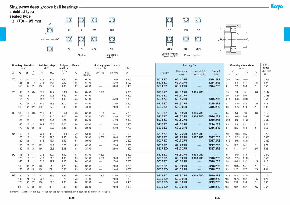
shielded typesealed type
Single-row deep groove ball bearings
B
r
r
u D u d
Z Z ZX RU RD RS RS
ZZ ZZ ZZX 2RU 2RD 2RS 2RS
Shielded Non-contactsealed
Extremely lightcontact sealed Contact sealed
ra
u Da u da
ra
Boundary dimensions Basic load ratings
Fatigue
Factor
Limiting speeds
(min
−
1
)
Bearing No. Mounting dimensions.
(Refer.)
Mass
Open type
(kg)
(mm) (kN)
load limit
Grease lub. Oil lub.
(mm)
d D Br
C
r
C
0r
(kN)
f
0
(RD, 2RD) (RS, 2RS) (Z)
ShieldedNon-contact
sealed
Extremely lightcontact sealed
Contactsealed
d
a
D
a
r
a
min.
C
u
min. max. max. max.
10
19 5 0.3 2.15 0.84 0.030 14.8 37 000
⎯
22 000 43 000
6800 ZZ 6800 2RU
⎯
6800 2RS
12 12 17 0.3 0.005
10
22 6 0.3 3.35 1.25 0.070 14.0 34 000
⎯
21 000 41 000
6900 ZZ 6900 2RU
⎯
6900 2RS
12 12.5 20 0.3 0.010
10
26 8 0.3 5.70 1.95 0.100 12.3 31 000 28 000 19 000 36 000
6000 ZZ 6000 2RU 6000 2RD 6000 2RS
12 13 24 0.3 0.019
10
30 9 0.6 6.40 2.40 0.120 13.2 24 000 22 000 16 000 29 000
6200 ZZ 6200 2RU 6200 2RD 6200 2RS
14 15 26 0.6 0.032
10
35 11 0.6 10.1 3.45 0.270 11.2 22 000 20 000 16 000 27 000
6300 ZZ 6300 2RU 6300 2RD 6300 2RS
14 16 31 0.6 0.053
12
21 5 0.3 2.40 1.05 0.040 15.3 33 000 30 000 20 000 39 000
6801 ZZ 6801 2RU 6801 2RD 6801 2RS
14 14 19 0.3 0.006
12
24 6 0.3 3.60 1.45 0.080 14.5 31 000 28 000 18 000 36 000
6901 ZZ 6901 2RU 6901 2RD 6901 2RS
14 14 22 0.3 0.011
12
28 8 0.3 6.40 2.40 0.120 13.2 27 000 24 000 17 000 32 000
6001 ZZ 6001 2RU 6001 2RD 6001 2RS
14 15 26 0.3 0.022
12
32 10 0.6 8.50 3.05 0.240 12.3 22 000 20 000 15 000 27 000
6201 ZZ 6201 2RU 6201 2RD 6201 2RS
16 16.5 28 0.6 0.037
12
37 12 1 12.1 4.20 0.420 11.1 20 000 18 000 15 000 25 000
6301 ZZ 6301 2RU 6301 2RD 6301 2RS
17 17.5 32 1 0.060
15
24 5 0.3 2.60 1.25 0.050 15.8 28 000
⎯
16 000 33 000
6802 ZZ 6802 2RU
⎯
6802 2RS
17 17 22 0.3 0.007
15
28 7 0.3 5.40 2.25 0.120 14.3 26 000 23 000 15 000 30 000
6902 ZZ 6902 2RU 6902 2RD 6902 2RS
17 18 26 0.3 0.017
15
32 9 0.3 7.00 2.85 0.150 13.9 23 000 21 000 14 000 27 000
6002 ZZ 6002 2RU 6002 2RD 6002 2RS
17 18.5 30 0.3 0.030
15
35 11 0.6 9.55 3.75 0.290 13.2 20 000 18 000 13 000 24 000
6202 ZZ 6202 2RU 6202 2RD 6202 2RS
19 19.5 31 0.6 0.045
15
42 13 1 14.3 5.45 0.460 12.3 17 000 15 000 12 000 20 000
6302 ZZ 6302 2RU 6302 2RD 6302 2RS
20 21.5 37 1 0.082
17
26 5 0.3 3.30 1.55 0.060 15.7 26 000
⎯
14 000 30 000
6803 ZZ 6803 2RU
⎯
6803 2RS
19 19 24 0.3 0.008
17
30 7 0.3 5.75 2.55 0.130 14.7 23 000 21 000 13 000 28 000
6903 ZZ 6903 2RU 6903 2RD 6903 2RS
19 19.5 28 0.3 0.018
17
35 10 0.3 7.50 3.25 0.170 14.4 21 000 19 000 12 000 25 000
6003 ZZ 6003 2RU 6003 2RD 6003 2RS
19 21 33 0.3 0.039
17
40 12 0.6 12.0 4.80 0.370 13.2 17 000 15 000 12 000 21 000
6203 ZZ 6203 2RU 6203 2RD 6203 2RS
21 22 36 0.6 0.065
17
47 14 1 17.0 6.65 0.550 12.4 15 000 14 000 10 000 18 000
6303 ZZ 6303 2RU 6303 2RD 6303 2RS
22 24.3 42 1 0.115
20
32 7 0.3 5.00 2.45 0.100 15.5 21 000
⎯
12 000 25 000
6804 ZZ 6804 2RU
⎯
6804 2RS
22 22.5 30 0.3 0.018
20
37 9 0.3 7.95 3.70 0.190 14.7 19 000 17 000 11 000 23 000
6904 ZZ 6904 2RU 6904 2RD 6904 2RS
22 23.5 35 0.3 0.036
20
42 12 0.6 11.7 5.05 0.350 13.9 17 000 15 000 10 000 21 000
6004 ZZ 6004 2RU 6004 2RD 6004 2RS
24 25 38 0.6 0.069
20
47 14 1 16.0 6.65 0.510 13.2 15 000 14 000 9 700 17 000
6204 ZZ 6204 2RU 6204 2RD 6204 2RS
25 26.5 42 1 0.106
20
52 15 1.1 19.9 7.85 0.660 12.3 14 000 13 000 9 500 17 000
6304 ZZ 6304 2RU 6304 2RD 6304 2RS
26.5 27 45.5 1 0.144
22
44 12 0.6 11.7 5.15 0.350 14.1 17 000 15 000 9 900 20 000
60/22 ZZ 60/22 2RU 60/22 2RD 60/22 2RS
26 26.5 40 0.6 0.073
22
50 14 1 16.0 6.65 0.510 13.2 15 000 14 000 9 700 17 000
62/22 ZZ 62/22 2RU 62/22 2RD 62/22 2RS
27 27 45 1 0.118
[Remark] Standard cage types used for the above bearings are described earlier in this section.
Z, ZZRU, 2RU
B 20 B 21
d
10
∼
(
22
)
mm

shielded typesealed type
Single-row deep groove ball bearings
B
r
r
u D u d
Z Z ZX RU RD RS RS
ZZ ZZ ZZX 2RU 2RD 2RS 2RS
Shielded Non-contactsealed
Extremely lightcontact sealed Contact sealed
ra
u Da u da
ra
22
56 16 1.1 23.1 9.40 0.770 12.6 13 000 12 000 8 600 15 000
63/22 ZZ 63/22 2RU 63/22 2RD 63/22 2RS
28.5 29 49.5 1 0.201
25
37 7 0.3 5.40 2.95 0.120 16.0 18 000
⎯
10 000 21 000
6805 ZZ 6805 2RU
⎯
6805 2RS
27 27.5 35 0.3 0.022
25
42 9 0.3 8.75 4.55 0.230 15.4 16 000 14 000 9 300 19 000
6905 ZZ 6905 2RU 6905 2RD 6905 2RS
27 29 40 0.3 0.041
25
47 12 0.6 12.6 5.85 0.380 14.5 15 000 14 000 9 000 18 000
6005 ZZ 6005 2RU 6005 2RD 6005 2RS
29 29.5 43 0.6 0.080
25
52 15 1 17.5 7.85 0.550 13.9 13 000 12 000 8 400 15 000
6205 ZZ 6205 2RU 6205 2RD 6205 2RS
30 31.5 47 1 0.128
25
62 17 1.1 25.7 11.3 0.860 13.2 11 000 9 900 7 500 13 000
6305 ZZ 6305 2RU 6305 2RD 6305 2RS
31.5 34 55.5 1 0.232
28
52 12 0.6 15.6 7.40 0.480 14.5 14 000 13 000 8 100 16 000
60/28 ZZ 60/28 2RU 60/28 2RD 60/28 2RS1
32 33 48 0.6 0.097
28
58 16 1 22.4 9.75 0.720 13.4 12 000 11 000 7 600 14 000
62/28 ZZ 62/28 2RU 62/28 2RD 62/28 2RS
33 35 53 1 0.173
28
68 18 1.1 29.4 13.1 0.990 13.3 10 000 9 000 6 900 12 000
63/28 ZZ 63/28 2RU 63/28 2RD 63/28 2RS
34.5 37.5 61.5 1 0.328
30
42 7 0.3 5.65 3.40 0.140 16.4 15 000
⎯
8 600 18 000
6806 ZZ 6806 2RU
⎯
6806 2RS
32 32.5 40 0.3 0.026
30
47 9 0.3 9.05 5.00 0.260 15.8 14 000 13 000 8 200 17 000
6906 ZZ 6906 2RU 6906 2RD 6906 2RS
32 33 45 0.3 0.045
30
55 13 1 16.5 8.25 0.530 14.7 13 000 12 000 7 500 15 000
6006 ZZ 6006 2RU 6006 2RD 6006 2RS
35 36 50 1 0.116
30
62 16 1 24.3 11.3 0.800 13.9 11 000 9 900 7 000 13 000
6206 ZZ 6206 2RU 6206 2RD 6206 2RS
35 37.5 57 1 0.199
30
72 19 1.1 33.3 15.0 1.15 13.3 9 600 8 600 6 400 12 000
6306 ZZ 6306 2RU 6306 2RD 6306 2RS
36.5 40 65.5 1 0.346
32
58 13 1 18.8 9.15 0.600 14.5 12 000 11 000 7 200 14 000
60/32 ZZ 60/32 2RU 60/32 2RD 60/32 2RS
37 38 53 1 0.127
32
65 17 1 29.4 13.1 0.990 13.3 10 000 9 000 6 900 12 000
62/32 ZZ 62/32 2RU 62/32 2RD 62/32 2RS
37 38.5 60 1 0.228
32
75 20 1.1 37.6 16.2 1.30 12.7 9 300 8 400 6 400 11 000
63/32 ZZ 63/32 2RU 63/32 2RD 63/32 2RS
38.5 41 68.5 1 0.437
35
47 7 0.3 5.95 3.85 0.160 16.5 13 000
⎯
7 400 16 000
6807 ZZ 6807 2RU
⎯
6807 2RS
37 37.5 45 0.3 0.030
35
55 10 0.6 13.6 7.75 0.440 15.7 12 000 11 000 6 800 14 000
6907 ZZ 6907 2RU 6907 2RD 6907 2RS
39 40 51 0.6 0.073
35
62 14 1 19.9 10.3 0.640 14.9 11 000 9 900 6 500 13 000
6007 ZZ 6007 2RU 6007 2RD 6007 2RS
40 42 58 1 0.155
35
72 17 1.1 32.1 15.4 1.10 13.9 9 200 8 300 6 000 11 000
6207 ZZ 6207 2RU 6207 2RD 6207 2RS
41.5 43.5 65.5 1 0.288
35
80 21 1.5 41.7 19.3 1.45 13.2 8 500 7 700 5 700 10 000
6307 ZZ 6307 2RU 6307 2RD 6307 2RS
43 46 72 1.5 0.457
40
52 7 0.3 6.15 4.20 0.180 16.3 12 000 11 000 6 700 14 000
6808 ZZ 6808 2RU 6808 2RD 6808 2RS
42 42 50 0.3 0.033
40
62 12 0.6 17.1 9.95 0.570 15.6 11 000 9 900 6 100 13 000
6908 ZZ 6908 2RU 6908 2RD 6908 2RS
44 44.5 58 0.6 0.112
40
68 15 1 20.9 11.5 0.690 15.2 10 000 9 000 5 800 12 000
6008 ZZ 6008 2RU 6008 2RD 6008 2RS
45 46.5 63 1 0.192
40
80 18 1.1 36.4 17.8 1.25 14.0 8 300 7 500 5 400 10 000
6208 ZZ 6208 2RU 6208 2RD 6208 2RS
46.5 49 73.5 1 0.366
40
90 23 1.5 50.9 24.0 1.85 13.2 7 700 6 900 5 100 9 200
6308 ZZ 6308 2RU 6308 2RD 6308 2RS
48 51.5 82 1.5 0.633
Boundary dimensions Basic load ratings
Fatigue
Factor
Limiting speeds
(min
−
1
)
Bearing No. Mounting dimensions.
(Refer.)
Mass
Open type
(kg)
(mm) (kN)
load limit
Grease lub. Oil lub.
(mm)
d D Br
C
r
C
0r
(kN)
f
0
(RD, 2RD) (RS, 2RS) (Z)
ShieldedNon-contact
sealed
Extremely lightcontact sealed
Contactsealed
d
a
D
a
r
a
min.
C
u
min. max. max. max.
[Remark] Standard cage types used for the above bearings are described earlier in this section.
Z, ZZRU, 2RU
B 22 B 23
d
(
22
)
∼
40 mm

shielded typesealed type
Single-row deep groove ball bearings
B
r
r
u D u d
Z Z ZX RU RD RS RS
ZZ ZZ ZZX 2RU 2RD 2RS 2RS
Shielded Non-contactsealed
Extremely lightcontact sealed Contact sealed
ra
u Da u da
ra
45
58 7 0.3 7.75 5.40 0.230 16.3 11 000 9 900 5 900 13 000
6809 ZZ 6809 2RU 6809 2RD 6809 2RS
47 47 56 0.3 0.040
45
68 12 0.6 17.7 10.9 0.600 15.9 9 700 8 700 5 500 11 000
6909 ZZ 6909 2RU 6909 2RD 6909 2RS
49 50 64 0.6 0.132
45
75 16 1 26.2 15.1 0.900 15.3 9 200 8 300 5 300 11 000
6009 ZZ 6009 2RU 6009 2RD 6009 2RS
50 51.5 70 1 0.245
45
85 19 1.1 40.9 20.3 1.40 14.0 7 700 6 900 5 100 9 200
6209 ZZ 6209 2RU 6209 2RD 6209 2RS
51.5 53.5 78.5 1 0.407
45
100 25 1.5 61.1 29.5 2.25 13.3 6 800 6 100 4 500 8 100
6309 ZZ 6309 2RU 6309 2RD 6309 2RS
53 59.5 92 1.5 0.833
50
65 7 0.3 8.20 6.10 0.260 16.1 9 600 8 600 5 200 11 000
6810 ZZ 6810 2RU 6810 2RD 6810 2RS
52 53 63 0.3 0.052
50
72 12 0.6 18.2 11.7 0.640 16.1 9 000
⎯
5 000 11 000
6910 ZZ 6910 2RU
⎯ ⎯
54 55.5 68 0.6 0.133
50
80 16 1 27.3 16.6 0.960 15.6 8 400 7 600 4 800 9 900
6010 ZZ 6010 2RU 6010 2RD 6010 2RS
55 57 75 1 0.261
50
90 20 1.1 43.9 23.3 1.55 14.4 7 100 6 400 4 600 8 500
6210 ZZ 6210 2RU 6210 2RD 6210 2RS
56.5 59 83.5 1 0.463
50 110 27 2 77.5 38.3 2.90 13.2 6 100 5 500 4 100 7 300 6310 ZZ 6310 2RU 6310 2RD 6310 2RS 59 66.5 101 2 1.07
55 72 9 0.3 11.0 8.10 0.420 16.2 8 700 7 800 ⎯ 10 000 6811 ZZ 6811 2RU 6811 2RD ⎯ 57 58.5 70 0.3 0.08355 80 13 1 20.8 14.1 0.760 16.2 8 100 7 300 4 500 9 600 6911 ZZ 6911 2RU 6911 2RD 6911 2RS 60 60.5 75 1 0.18555 90 18 1.1 35.3 21.2 1.25 15.3 7 600 6 800 4 300 8 900 6011 ZZ 6011 2RU 6011 2RD 6011 2RS 61.5 62 83.5 1 0.385
55 100 21 1.5 54.2 29.4 1.95 14.4 6 300 5 700 4 100 7 600 6211 ZZ 6211 2RU 6211 2RD 6211 2RS 63 66 92 1.5 0.60755 120 29 2 89.5 45.0 3.45 13.2 5 600 ⎯ 3 700 6 700 6311 ZZ 6311 2RU ⎯ 6311 2RS 64 74.5 111 2 1.37
60 78 10 0.3 14.3 10.6 0.550 16.3 8 000 7 200 ⎯ 9 400 6812 ZZ 6812 2RU 6812 2RD ⎯ 62 63 76 0.3 0.10460 85 13 1 25.2 17.3 0.940 16.2 7 500 ⎯ ⎯ 8 900 6912 ZZ 6912 2RU ⎯ ⎯ 65 66 80 1 0.19260 95 18 1.1 36.8 23.2 1.35 15.6 7 100 ⎯ 4 000 8 400 6012 ZZ 6012 2RU ⎯ 6012 2RS 66.5 68.5 88.5 1 0.415
60 110 22 1.5 65.6 36.2 2.40 14.4 5 700 5 100 3 700 6 900 6212 ZZ 6212 2RU 6212 2RD 6212 2RS 68 72.5 102 1.5 0.78360 130 31 2.1 102 52.2 3.95 13.2 5 200 ⎯ 3 500 6 200 6312 ZZ 6312 2RU ⎯ 6312 2RS 71 80 119 2 1.70
65 85 10 0.6 14.9 11.5 0.590 16.2 7 300 6 600 ⎯ 8 600 6813 ZZ 6813 2RU 6813 2RD ⎯ 69 69 81 0.6 0.12665 90 13 1 21.7 16.1 0.830 16.6 7 100 6 400 3 900 8 400 6913 ZZ 6913 2RU 6913 2RD 6913 2RS 70 71 85 1 0.21165 100 18 1.1 38.1 25.2 1.40 15.8 6 600 ⎯ 3 700 7 800 6013 ZZ 6013 2RU ⎯ 6013 2RS 71.5 74.5 93.5 1 0.435
65 120 23 1.5 71.5 40.1 2.65 14.4 5 400 ⎯ 3 500 6 400 6213 ZZ 6213 2RU ⎯ 6213 2RS 73 79 112 1.5 0.99065 140 33 2.1 116 59.9 4.50 13.2 4 800 ⎯ 3 200 5 800 6313 ZZ 6313 2RU ⎯ 6313 2RS 76 86 129 2 2.08
70 90 10 0.6 15.1 11.9 0.620 16.1 6 800 6 100 ⎯ 8 100 6814 ZZ 6814 2RU 6814 2RD ⎯ 74 74 86 0.6 0.13470 100 16 1 29.7 21.2 1.10 16.3 6 400 5 800 3 600 7 600 6914 ZZ 6914 2RU 6914 2RD 6914 2RS 75 76.5 95 1 0.342
Boundary dimensions Basic load ratings Fatigue Factor Limiting speeds (min−1) Bearing No. Mounting dimensions. (Refer.)
MassOpen type
(kg)
(mm) (kN) load limit Grease lub. Oil lub. (mm)
d D Br
Cr C0r(kN)
f 0 (RD, 2RD) (RS, 2RS) (Z) ShieldedNon-contact
sealedExtremely lightcontact sealed
Contactsealed
da Da ramin. Cu min. max. max. max.
[Remark] Standard cage types used for the above bearings are described earlier in this section.
Z, ZZRU, 2RU
B 24 B 25
d 45 ∼ (70) mm
shielded typesealed type
Single-row deep groove ball bearings
B
r
r
u D u d
Z Z ZX RU RD RS RS
ZZ ZZ ZZX 2RU 2RD 2RS 2RS
Shielded Non-contactsealed
Extremely lightcontact sealed Contact sealed
ra
u Da u da
ra
70 110 20 1.1 47.6 30.9 1.80 15.6 6 100 ⎯ 3 500 7 200 6014 ZZ 6014 2RU ⎯ 6014 2RS 76.5 79.5 103.5 1 0.60270 125 24 1.5 77.8 44.1 2.90 14.5 5 100 ⎯ 3 300 6 100 6214 ZZ 6214 2RU ⎯ 6214 2RS 78 84 117 1.5 1.0770 150 35 2.1 130 68.2 4.95 13.2 4 500 ⎯ 3 000 5 400 6314 ZZ 6314 2RU ⎯ 6314 2RS 81 92 139 2 2.52
75 95 10 0.6 15.7 12.9 0.660 16.0 6 400 5 800 ⎯ 7 600 6815 ZZ 6815 2RU 6815 2RD ⎯ 79 79 91 0.6 0.14275 105 16 1 30.5 22.6 1.20 16.5 6 100 ⎯ ⎯ 7 200 6915 ZZ 6915 2RU ⎯ ⎯ 80 82.5 100 1 0.36375 115 20 1.1 49.4 33.5 1.90 15.8 5 700 ⎯ 3 300 6 800 6015 ZZ 6015 2RU ⎯ 6015 2RS 81.5 84.5 108.5 1 0.638
75 130 25 1.5 84.3 48.3 3.10 14.5 4 800 ⎯ 3 100 5 800 6215 ZZ 6215 2RU ⎯ 6215 2RS 83 88.5 122 1.5 1.1875 160 37 2.1 142 77.2 5.40 13.2 4 200 ⎯ 2 800 5 000 6315 ZZ 6315 2RU ⎯ 6315 2RS 86 97.5 149 2 3.02
80 100 10 0.6 15.9 13.3 0.690 16.0 6 100 5 500 ⎯ 7 200 6816 ZZ 6816 2RU 6816 2RD ⎯ 84 84 96 0.6 0.15080 110 16 1 31.2 24.0 1.25 16.6 5 700 5 100 3 200 6 800 6916 ZZ 6916 2RU 6916 2RD 6916 2RS 85 86.5 105 1 0.38280 125 22 1.1 59.5 39.8 2.25 15.6 5 300 ⎯ 3 100 6 300 6016 ZZ 6016 2RU ⎯ 6016 2RS 86.5 90 118.5 1 0.850
80 140 26 2 90.9 53.0 3.25 14.6 4 500 ⎯ 2 900 5 400 6216 ZZ 6216 2RU ⎯ 6216 2RS 89 93 131 2 1.4080 170 39 2.1 154 86.7 5.85 13.3 3 900 ⎯ 2 700 4 700 6316 ZZ 6316 2RU ⎯ 6316 2RS 91 105 159 2 3.59
85 110 13 1 23.4 19.0 0.980 16.2 5 600 5 000 ⎯ 6 600 6817 ZZ 6817 2RU 6817 2RD ⎯ 90 90.5 105 1 0.26685 120 18 1.1 39.9 29.6 1.55 16.4 5 300 4 800 3 000 6 300 6917 ZZ 6917 2RU 6917 2RD 6917 2RS 91.5 92.5 113.5 1 0.53585 130 22 1.1 61.8 43.1 2.35 15.8 5 000 ⎯ 2 900 5 900 6017 ZZ 6017 2RU ⎯ 6017 2RS 91.5 96.5 123.5 1 0.890
85 150 28 2 105 61.9 3.70 14.5 4 200 ⎯ 2 700 5 000 6217 ZZ 6217 2RU ⎯ 6217 2RS 94 102 141 2 1.7985 180 41 3 166 96.8 6.35 13.3 3 700 ⎯ 2 500 4 400 6317 ZZX 6317 2RU ⎯ 6317 2RS 98 111 167 2.5 4.23
90 115 13 1 23.8 19.7 1.00 16.1 5 300 4 800 ⎯ 6 300 6818 ZZ 6818 2RU 6818 2RD ⎯ 95 95.5 110 1 0.27990 125 18 1.1 41.0 31.6 1.60 16.5 5 100 4 600 2 800 6 000 6918 ZZ 6918 2RU 6918 2RD 6918 2RS 96.5 97.5 118.5 1 0.56590 140 24 1.5 72.8 49.7 2.65 15.6 4 700 ⎯ 2 700 5 600 6018 ZZ 6018 2RU ⎯ 6018 2RS 98 100.5 132 1.5 1.16
90 160 30 2 120 71.5 4.20 14.5 3 900 ⎯ 2 600 4 700 6218 ZZ 6218 2RU ⎯ 6218 2RS 99 108.5 151 2 2.1590 190 43 3 178 107 8.80 13.3 3 500 ⎯ 2 400 4 200 6318 ZZX 6318 2RU ⎯ 6318 2RS 103 117 177 2.5 4.91
95 130 18 1.1 42.1 33.5 1.65 16.6 4 800 4 300 2 700 5 700 6919 ZZ 6919 2RU 6919 2RD 6919 2RS 101.5 102 123.5 1 0.70595 145 24 1.5 75.5 53.9 2.75 15.8 4 400 ⎯ 2 500 5 200 6019 ZZX 6019 2RU ⎯ 6019 2RS 103 107.5 137 1.5 1.2195 170 32 2.1 136 81.9 4.65 14.4 3 700 ⎯ 2 400 4 400 6219 ZZX 6219 2RU ⎯ 6219 2RS 106 113 159 2 2.62
95 200 45 3 191 119 9.45 13.3 3 300 ⎯ 2 200 4 000 6319 ZZX 6319 2RU ⎯ 6319 2RS 108 122 187 2.5 5.67
Boundary dimensions Basic load ratings Fatigue Factor Limiting speeds (min−1) Bearing No. Mounting dimensions. (Refer.)
MassOpen type
(kg)
(mm) (kN) load limit Grease lub. Oil lub. (mm)
d D Br
Cr C0r(kN)
f 0 (RD, 2RD) (RS, 2RS) (Z) ShieldedNon-contact
sealedExtremely lightcontact sealed
Contactsealed
da Da ramin. Cu min. max. max. max.
[Remark] Standard cage types used for the above bearings are described earlier in this section.
Z, ZZRU, 2RU
B 26 B 27
d (70) ∼ 95 mm

shielded typesealed type
Single-row deep groove ball bearings
B
r
r
u D u d
Z Z ZX RU RD RS RS
ZZ ZZ ZZX 2RU 2RD 2RS 2RS
Shielded Non-contactsealed
Extremely lightcontact sealed Contact sealed
ra
u Da u da
ra
100 125 13 1 24.5 21.2 1.05 16.0 4 800 4 300 ⎯ 5 700 6820 ZZ 6820 2RU 6820 2RD ⎯ 105 105.5 120 1 0.309100 140 20 1.1 51.5 39.6 1.90 16.2 4 500 ⎯ ⎯ 5 300 6920-1 ZZ 6920-1 2RU ⎯ ⎯ 106.5 110.5 133.5 1 0.960100 150 24 1.5 75.2 54.2 2.70 15.9 4 300 ⎯ 2 500 5 100 6020 ZZ 6020 2RU ⎯ 6020 2RS 108 112 142 1.5 1.25
100 180 34 2.1 153 93.1 5.15 14.4 3 500 ⎯ 2 300 4 200 6220 ZZX 6220 2RU ⎯ 6220 2RS 111 122 169 2 3.14100 215 47 3 216 141 10.9 13.2 3 000 ⎯ 2 100 3 600 6320 ZZX 6320 2RU ⎯ 6320 2RS 113 131 202 2.5 7.00
105 145 20 1.1 53.0 42.1 1.95 16.4 4 300 ⎯ 2 400 5 100 6921-1 ZZ 6921-1 2RU ⎯ 6921-1 2RS 111.5 115 138.5 1 1.00105 160 26 2 90.4 65.8 3.20 15.8 4 000 ⎯ 2 300 4 700 6021 ZZX 6021 2RU ⎯ 6021 2RS 114 119 151 2 1.59105 190 36 2.1 166 105 5.70 14.4 3 300 ⎯ 2 200 3 900 6221 ZZX 6221 2RU ⎯ 6221 2RS 116 127 179 2 3.70
105 225 49 3 230 153 11.7 13.2 2 900 ⎯ 2 000 3 500 6321 ZZX 6321 2RU ⎯ 6321 2RS 118 136 212 2.5 8.05
110 140 16 1 35.1 30.7 1.40 16.1 4 300 3 900 ⎯ 5 100 6822 ZZ 6822 2RU 6822 2RD ⎯ 115 116.5 135 1 0.606110 150 20 1.1 59.9 47.8 2.20 16.4 4 100 ⎯ ⎯ 4 900 6922 ZZ 6922 2RU ⎯ ⎯ 116.5 119.5 143.5 1 1.04110 170 28 2 103 73.0 3.55 15.6 3 800 ⎯ 2 200 4 500 6022 ZZX 6022 2RU ⎯ 6022 2RS 119 123 161 2 1.96
110 200 38 2.1 180 117 6.20 14.4 3 100 ⎯ 2 000 3 700 6222 ZZX 6222 2RU ⎯ 6222 2RS 121 136.5 189 2 4.36110 240 50 3 257 180 13.3 13.2 2 700 ⎯ 1 900 3 200 6322 ZZX 6322 2RU ⎯ 6322 2RS 123 146.5 227 2.5 9.54
120 150 16 1 36.2 33.0 1.45 16.0 4 000 ⎯ ⎯ 4 700 6824 ZZ 6824 2RU ⎯ ⎯ 125 128.5 145 1 0.655120 165 22 1.1 71.6 56.9 2.50 16.4 3 800 ⎯ ⎯ 4 400 6924 ZZ 6924 2RU ⎯ ⎯ 126.5 131.5 158.5 1 1.41120 180 28 2 106 79.3 3.60 15.9 3 600 ⎯ 2 100 4 200 6024 ZZX 6024 2RU ⎯ 6024 2RS 129 136 171 2 2.07
120 215 40 2.1 194 131 6.65 14.4 2 900 ⎯ 1 900 3 400 6224 ZZX 6224 2RU ⎯ 6224 2RS 131 144 204 2 5.15120 260 55 3 258 185 12.6 13.5 2 500 ⎯ ⎯ 3 000 6324 ZZX ⎯ ⎯ ⎯ 133 158 247 2.5 12.5
130 165 18 1.1 46.1 41.2 1.75 16.1 3 600 ⎯ ⎯ 4 300 6826 ZZ 6826 2RU ⎯ ⎯ 136.5 139.5 158.5 1 0.939130 180 24 1.5 81.5 67.4 2.85 16.3 3 400 ⎯ ⎯ 4 100 6926-1 ZZ 6926-1 2RU ⎯ ⎯ 138 144 172 1.5 1.86130 200 33 2 133 101 4.45 15.8 3 200 ⎯ 1 900 3 800 6026 ZZX 6026 2RU ⎯ 6026 2RS 139 146.5 191 2 3.16
130 230 40 3 209 146 9.15 14.5 2 700 ⎯ 1 800 3 200 6226 ZZX 6226 2RU ⎯ 6226 2RS 143 157 217 2.5 5.82130 280 58 4 287 214 14.1 13.6 2 300 ⎯ ⎯ 2 700 6326 ZZX ⎯ ⎯ ⎯ 146 171 264 3 15.1
140 175 18 1.1 47.8 44.4 1.85 16.0 3 400 3 100 ⎯ 4 000 6828 ZZ ⎯ 6828 2RD ⎯ 146.5 148 168.5 1 1.00140 190 24 1.5 83.3 71.6 2.90 16.5 3 200 ⎯ ⎯ 3 800 6928-1 ZZ 6928-1 2RU ⎯ ⎯ 148 153 182 1.5 1.98140 210 33 2 137 109 4.55 15.9 3 000 ⎯ 1 800 3 600 6028 ZZX 6028 2RU ⎯ 6028 2RS 149 158.5 201 2 3.55
Boundary dimensions Basic load ratings Fatigue Factor Limiting speeds (min−1) Bearing No. Mounting dimensions. (Refer.)
MassOpen type
(kg)
(mm) (kN) load limit Grease lub. Oil lub. (mm)
d D Br
Cr C0r(kN)
f 0 (RD, 2RD) (RS, 2RS) (Z) ShieldedNon-contact
sealedExtremely lightcontact sealed
Contactsealed
da Da ramin. Cu min. max. max. max.
[Remark] Standard cage types used for the above bearings are described earlier in this section.
Z, ZZRU, 2RU
B 28 B 29
d 100 ∼ (140) mm

shielded typesealed type
Single-row deep groove ball bearings
B
r
r
u D u d
Z Z ZX RU RD RS RS
ZZ ZZ ZZX 2RU 2RD 2RS 2RS
Shielded Non-contactsealed
Extremely lightcontact sealed Contact sealed
ra
u Da u da
ra
140 250 42 3 208 150 8.65 14.8 2 400 ⎯ 1 600 2 900 6228 ZZX 6228 2RU ⎯ 6228 2RS 153 169 237 2.5 7.45140 300 62 4 316 246 15.6 13.6 2 100 ⎯ ⎯ 2 500 6328 ZZX ⎯ ⎯ ⎯ 156 184 284 3 19.4
150 210 28 2 117 94.3 3.75 16.2 2 900 ⎯ 1 700 3 400 6930 ZZ 6930 2RU ⎯ 6930 2RS 159 165.5 201 2 3.05150 225 35 2.1 157 126 5.10 16.0 2 800 ⎯ 1 600 3 300 6030 ZZX 6030 2RU ⎯ 6030 2RS 161 168.5 214 2 4.22150 270 45 3 220 168 9.05 15.1 2 200 ⎯ ⎯ 2 700 6230 ZZX ⎯ ⎯ ⎯ 163 183.5 257 2.5 9.41
160 200 20 1.1 60.5 56.9 2.20 16.1 2 900 2 600 ⎯ 3 400 6832 ZZ ⎯ 6832 2RD ⎯ 166.5 168.5 193.5 1 1.45160 240 38 2.1 171 135 5.30 15.9 2 600 ⎯ 1 500 3 000 6032 ZZX 6032 2RU ⎯ 6032 2RS 171 178.5 229 2 5.22160 290 48 3 231 186 9.45 15.4 2 100 ⎯ ⎯ 2 500 6232 ZZX ⎯ ⎯ ⎯ 173 198 277 2.5 14.3
170 215 22 1.1 74.8 70.5 2.60 16.1 2 700 ⎯ ⎯ 3 200 6834 ZZ ⎯ ⎯ ⎯ 176.5 182.5 208.5 1 1.90170 260 42 2.1 201 161 6.20 15.8 2 400 ⎯ ⎯ 2 800 6034 ZZX 6034 2RU ⎯ ⎯ 181 194 249 2 6.80170 310 52 4 265 223 11.1 15.3 1 900 ⎯ ⎯ 2 300 6234 ZZX ⎯ ⎯ ⎯ 186 210.5 294 3 17.5
180 225 22 1.1 75.8 73.1 2.65 16.1 2 600 2 300 ⎯ 3 000 6836 ZZ ⎯ 6836 2RD ⎯ 186.5 189.5 218.5 1 2.00180 280 46 2.1 227 194 7.15 15.8 2 200 ⎯ ⎯ 2 600 6036 ZZX 6036 2RU ⎯ ⎯ 191 209.5 269 2 10.3180 320 52 4 264 226 10.8 15.1 1 800 ⎯ ⎯ 2 200 6236-1 ZZX ⎯ ⎯ ⎯ 196 220.5 304 3 18.3
190 240 24 1.5 91.4 88.1 3.10 16.1 2 400 ⎯ ⎯ 2 800 6838 ZZ ⎯ ⎯ ⎯ 198 202 232 1.5 2.60190 290 46 2.1 235 201 7.35 15.8 2 100 ⎯ ⎯ 2 500 6038 ZZX ⎯ ⎯ ⎯ 201 215 279 2 10.8
200 310 51 2.1 272 243 11.3 15.6 1 900 ⎯ ⎯ 2 300 6040 ZZX ⎯ ⎯ ⎯ 211 228 299 2 14.0200 360 58 4 314 293 13.1 15.2 1 600 ⎯ ⎯ 1 900 6240-1 ZZX ⎯ ⎯ ⎯ 216 250 344 3 28.2
220 340 56 3 294 271 12.0 15.6 1 700 ⎯ ⎯ 2 000 6044 ZZX ⎯ ⎯ ⎯ 233 251 327 2.5 18.3
Boundary dimensions Basic load ratings Fatigue Factor Limiting speeds (min−1) Bearing No. Mounting dimensions. (Refer.)
MassOpen type
(kg)
(mm) (kN) load limit Grease lub. Oil lub. (mm)
d D Br
Cr C0r(kN)
f 0 (RD, 2RD) (RS, 2RS) (Z) ShieldedNon-contact
sealedExtremely lightcontact sealed
Contactsealed
da Da ramin. Cu min. max. max. max.
[Remark] Standard cage types used for the above bearings are described earlier in this section.
Z, ZZRU, 2RU
B 30 B 31
d (140) ∼ 220 mm

r
r
r1
u D u d
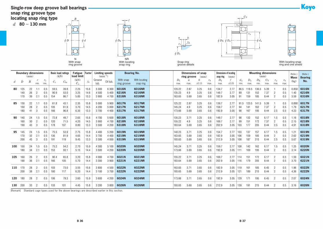
NWith snapring groove
B ƒ
a bu D2
u D1
NRWith locatingsnap ring
Snap ringgroove details
r1r0
With locating snapring and one shield
u DX u da
ra
u Da
rb
CY
snap ring groove typelocating snap ring type
Single-row deep groove ball bearings
Boundary dimensions
Basic load ratings
Fatigue
Factor Limiting speeds
Bearing No. Dimensions of snapring groove
(mm)
Dimensions of locatingsnap ring
(mm)
Mounting dimensions
(Refer.)
Mass
(kg)
(Refer.)
Bearing No.
(mm) (kN)
load limit
(min
−
1
) (mm)
d D Br r
1
C
r
C
0r
(kN)
f
0
Greaselub.
Oil lub.With snap
ring groove
With locating snap ring
D
1
a b r
0
D
2
f
d
a
D
a
D
X
C
Y
r
a
r
b
min. min.
C
u
max. max.
±
0.15 max. max.
±
0.05 min. max. min. max. max. max.
10
30 9 0.6 0.3 6.40 2.40 0.120 13.2 24 000 29 000
6200N 6200NR
28.17 2.06 1.5 0.4 34.7 1.07 14 26 35.5 2.92 0.6 0.3 0.032
6200N10
35 11 0.6 0.5 10.1 3.45 0.270 11.2 22 000 27 000
6300N 6300NR
33.17 2.06 1.5 0.4 39.7 1.07 14 31 40.5 2.92 0.6 0.5 0.053
6300N
12
32 10 0.6 0.3 8.50 3.05 0.240 12.3 22 000 27 000
6201N 6201NR
30.15 2.06 1.5 0.4 36.7 1.07 16 28 37.5 2.92 0.6 0.3 0.037
6201N12
37 12 1 0.5 12.1 4.20 0.420 11.1 20 000 25 000
6301N 6301NR
34.77 2.06 1.5 0.4 41.3 1.07 17 32 42 2.92 1 0.5 0.060
6301N
15
35 11 0.6 0.5 9.55 3.75 0.290 13.2 20 000 24 000
6202N 6202NR
33.17 2.06 1.5 0.4 39.7 1.07 19 31 40.5 2.92 0.6 0.5 0.045
6202N15
42 13 1 0.5 14.3 5.45 0.460 12.3 17 000 20 000
6302N 6302NR
39.75 2.06 1.5 0.4 46.3 1.07 20 37 47 2.92 1 0.5 0.082
6302N
17
40 12 0.6 0.5 12.0 4.80 0.370 13.2 17 000 21 000
6203N 6203NR
38.1 2.06 1.5 0.4 44.6 1.07 21 36 45.5 2.92 0.6 0.5 0.065
6203N17
47 14 1 0.5 17.0 6.65 0.550 12.4 15 000 18 000
6303N 6303NR
44.6 2.46 1.5 0.4 52.7 1.07 22 42 53.5 3.33 1 0.5 0.115
6303N
20
42 12 0.6 0.5 11.7 5.05 0.350 13.9 17 000 21 000
6004N 6004NR
39.75 2.06 1.5 0.4 46.3 1.07 24 38 47 2.92 0.6 0.5 0.069
6004N20
47 14 1 0.5 16.0 6.65 0.510 13.2 15 000 17 000
6204N 6204NR
44.6 2.46 1.5 0.4 52.7 1.07 25 42 53.5 3.33 1 0.5 0.106
6204N20
52 15 1.1 0.5 19.9 7.85 0.660 12.3 14 000 17 000
6304N 6304NR
49.73 2.46 1.5 0.4 57.9 1.07 26.5 45.5 58.5 3.33 1 0.5 0.144
6304N
22
44 12 0.6 0.5 11.7 5.15 0.350 14.1 17 000 20 000
60/22N 60/22NR
41.75 2.06 1.5 0.4 48.3 1.07 26 40 49 2.92 0.6 0.5 0.073
60/22N22
50 14 1 0.5 16.0 6.65 0.510 13.2 15 000 17 000
62/22N 62/22NR
47.6 2.46 1.5 0.4 55.7 1.07 27 45 56.5 3.33 1 0.5 0.118
62/22N22
56 16 1.1 0.5 23.1 9.40 0.770 12.6 13 000 15 000
63/22N 63/22NR
53.6 2.46 1.5 0.4 61.7 1.07 28.5 49.5 62.5 3.33 1 0.5 0.201
63/22N
25
47 12 0.6 0.5 12.6 5.85 0.380 14.5 15 000 18 000
6005N 6005NR
44.6 2.06 1.5 0.4 52.7 1.07 29 43 53.5 2.92 0.6 0.5 0.080
6005N25
52 15 1 0.5 17.5 7.85 0.550 13.9 13 000 15 000
6205N 6205NR
49.73 2.46 1.5 0.4 57.9 1.07 30 47 58.5 3.33 1 0.5 0.128
6205N25
62 17 1.1 0.5 25.7 11.3 0.860 13.2 11 000 13 000
6305N 6305NR
59.61 3.28 2.05 0.6 67.7 1.65 31.5 55.5 68.5 4.67 1 0.5 0.232
6305N
28
52 12 0.6 0.5 15.6 7.40 0.480 14.5 14 000 16 000
60/28N 60/28NR
49.73 2.06 1.5 0.4 57.9 1.07 32 48 58.5 2.92 0.6 0.5 0.097
60/28N28
58 16 1 0.5 22.4 9.75 0.720 13.4 12 000 14 000
62/28N 62/28NR
55.6 2.46 1.5 0.4 63.7 1.07 33 53 64.5 3.33 1 0.5 0.173
62/28N28
68 18 1.1 0.5 29.4 13.1 0.990 13.3 10 000 12 000
63/28N 63/28NR
64.82 3.28 2.05 0.6 74.6 1.65 34.5 61.5 76 4.67 1 0.5 0.328
63/28N
30
55 13 1 0.5 16.5 8.25 0.530 14.7 13 000 15 000
6006N 6006NR
52.6 2.08 1.5 0.4 60.7 1.07 35 50 61.5 2.9 1 0.5 0.116
6006N30
62 16 1 0.5 24.3 11.3 0.800 13.9 11 000 13 000
6206N 6206NR
59.61 3.28 2.05 0.6 67.7 1.65 35 57 68.5 4.67 1 0.5 0.199
6206N30
72 19 1.1 0.5 33.3 15.0 1.15 13.3 9 600 12 000
6306N 6306NR
68.81 3.28 2.05 0.6 78.6 1.65 36.5 65.5 80 4.67 1 0.5 0.346
6306N
32
58 13 1 0.5 18.8 9.15 0.600 14.5 12 000 14 000
60/32N 60/32NR
55.6 2.08 1.5 0.4 63.7 1.07 37 53 64.5 2.9 1 0.5 0.127
60/32N32
65 17 1 0.5 29.4 13.1 0.990 13.3 10 000 12 000
62/32N 62/32NR
62.6 3.28 2.05 0.6 70.7 1.65 37 60 71.5 4.67 1 0.5 0.228
62/32N32
75 20 1.1 0.5 37.6 16.2 1.30 12.7 9 300 11 000
63/32N 63/32NR
71.83 3.28 2.05 0.6 81.6 1.65 38.5 68.5 83 4.67 1 0.5 0.437
63/32N
[Remark] Standard cage types used for the above bearings are described earlier in this section.
B 32 B 33
d
10
∼
32 mm

r
r
r1
u D u d
NWith snapring groove
B ƒ
a bu D2
u D1
NRWith locatingsnap ring
Snap ringgroove details
r1r0
With locating snapring and one shield
u DX u da
ra
u Da
rb
CY
snap ring groove typelocating snap ring type
Single-row deep groove ball bearings
35
62 14 1 0.5 19.9 10.3 0.640 14.9 11 000 13 000
6007N 6007NR
59.61 2.08 2.05 0.6 67.7 1.65 40 58 68.5 3.48 1 0.5 0.155
6007N35
72 17 1.1 0.5 32.1 15.4 1.10 13.9 9 200 11 000
6207N 6207NR
68.81 3.28 2.05 0.6 78.6 1.65 41.5 65.5 80 4.67 1 0.5 0.288
6207N35
80 21 1.5 0.5 41.7 19.3 1.45 13.2 8 500 10 000
6307N 6307NR
76.81 3.28 2.05 0.6 86.6 1.65 43 72 88 4.67 1.5 0.5 0.457
6307N
40
68 15 1 0.5 20.9 11.5 0.690 15.2 10 000 12 000
6008N 6008NR
64.82 2.49 2.05 0.6 74.6 1.65 45 63 76 3.89 1 0.5 0.192
6008N40
80 18 1.1 0.5 36.4 17.8 1.25 14.0 8 300 10 000
6208N 6208NR
76.81 3.28 2.05 0.6 86.6 1.65 46.5 73.5 88 4.67 1 0.5 0.366
6208N40
90 23 1.5 0.5 50.9 24.0 1.85 13.2 7 700 9 200
6308N 6308NR
86.79 3.28 2.85 0.6 96.5 2.41 48 82 98 5.43 1.5 0.5 0.633
6308N
45
75 16 1 0.5 26.2 15.1 0.900 15.3 9 200 11 000
6009N 6009NR
71.83 2.49 2.05 0.6 81.6 1.65 50 70 83 3.89 1 0.5 0.245
6009N45
85 19 1.1 0.5 40.9 20.3 1.40 14.0 7 700 9 200
6209N 6209NR
81.81 3.28 2.05 0.6 91.6 1.65 51.5 78.5 93 4.67 1 0.5 0.407
6209N45
100 25 1.5 0.5 61.1 29.5 2.25 13.3 6 800 8 100
6309N 6309NR
96.8 3.28 2.85 0.6 106.5 2.41 53 92 108 5.43 1.5 0.5 0.833
6309N
50
80 16 1 0.5 27.3 16.6 0.960 15.6 8 400 9 900
6010N 6010NR
76.81 2.49 2.05 0.6 86.6 1.65 55 75 88 3.89 1 0.5 0.261
6010N50
90 20 1.1 0.5 43.9 23.3 1.55 14.4 7 100 8 500
6210N 6210NR
86.79 3.28 2.85 0.6 96.5 2.41 56.5 83.5 98 5.43 1 0.5 0.463
6210N50
110 27 2 0.5 77.5 38.3 2.90 13.2 6 100 7 300
6310N 6310NR
106.81 3.28 2.85 0.6 116.6 2.41 59 101 118 5.43 2 0.5 1.07
6310N
55
90 18 1.1 0.5 35.3 21.2 1.25 15.3 7 600 8 900
6011N 6011NR
86.79 2.87 2.85 0.6 96.5 2.41 61.5 83.5 98 5.03 1 0.5 0.385
6011N55
100 21 1.5 0.5 54.2 29.4 1.95 14.4 6 300 7 600
6211N 6211NR
96.8 3.28 2.85 0.6 106.5 2.41 63 92 108 5.43 1.5 0.5 0.607
6211N55
120 29 2 0.5 89.5 45.0 3.45 13.2 5 600 6 700
6311N 6311NR
115.21 4.06 3.25 0.6 129.7 2.77 64 111 131.5 6.58 2 0.5 1.37
6311N
60
95 18 1.1 0.5 36.8 23.2 1.35 15.6 7 100 8 400
6012N 6012NR
91.82 2.87 2.85 0.6 101.6 2.41 66.5 88.5 103 5.03 1 0.5 0.415
6012N60
110 22 1.5 0.5 65.6 36.2 2.40 14.4 5 700 6 900
6212N 6212NR
106.81 3.28 2.85 0.6 116.6 2.41 68 102 118 5.43 1.5 0.5 0.783
6212N60
130 31 2.1 0.5 102 52.2 3.95 13.2 5 200 6 200
6312N 6312NR
125.22 4.06 3.25 0.6 139.7 2.77 71 119 141.5 6.58 2 0.5 1.70
6312N
65
100 18 1.1 0.5 38.1 25.2 1.40 15.8 6 600 7 800
6013N 6013NR
96.8 2.87 2.85 0.6 106.5 2.41 71.5 93.5 108 5.03 1 0.5 0.435
6013N65
120 23 1.5 0.5 71.5 40.1 2.65 14.4 5 400 6 400
6213N 6213NR
115.21 4.06 3.25 0.6 129.7 2.77 73 112 131.5 6.58 1.5 0.5 0.990
6213N65
140 33 2.1 0.5 116 59.9 4.50 13.2 4 800 5 800
6313N 6313NR
135.23 4.9 3.25 0.6 149.7 2.77 76 129 152 7.37 2 0.5 2.08
6313N
70
110 20 1.1 0.5 47.6 30.9 1.80 15.6 6 100 7 200
6014N 6014NR
106.81 2.87 2.85 0.6 116.6 2.41 76.5 103.5 118 5.03 1 0.5 0.602
6014N70
125 24 1.5 0.5 77.8 44.1 2.90 14.5 5 100 6 100
6214N 6214NR
120.22 4.06 3.25 0.6 134.7 2.77 78 117 136.5 6.58 1.5 0.5 1.07
6214N70
150 35 2.1 0.5 130 68.2 4.95 13.2 4 500 5 400
6314N 6314NR
145.24 4.9 3.25 0.6 159.7 2.77 81 139 162 7.37 2 0.5 2.52
6314N
75
115 20 1.1 0.5 49.4 33.5 1.90 15.8 5 700 6 800
6015N 6015NR
111.81 2.87 2.85 0.6 121.6 2.41 81.5 108.5 123 5.03 1 0.5 0.638
6015N75
130 25 1.5 0.5 84.3 48.3 3.10 14.5 4 800 5 800
6215N 6215NR
125.22 4.06 3.25 0.6 139.7 2.77 83 122 141.5 6.58 1.5 0.5 1.18
6215N75
160 37 2.1 0.5 142 77.2 5.40 13.2 4 200 5 000
6315N 6315NR
155.22 4.9 3.25 0.6 169.7 2.77 86 149 172 7.37 2 0.5 3.02
6315N
Boundary dimensions
Basic load ratings
Fatigue
Factor Limiting speeds
Bearing No. Dimensions of snapring groove
(mm)
Dimensions of locatingsnap ring
(mm)
Mounting dimensions
(Refer.)
Mass
(kg)
(Refer.)
Bearing No.
(mm) (kN)
load limit
(min
−
1
) (mm)
d D Br r
1
C
r
C
0r
(kN)
f
0
Greaselub.
Oil lub.With snap
ring groove
With locating snap ring
D
1
a b r
0
D
2
f
d
a
D
a
D
X
C
Y
r
a
r
b
min. min.
C
u
max. max.
±
0.15 max. max.
±
0.05 min. max. min. max. max. max.
[Remark] Standard cage types used for the above bearings are described earlier in this section.
B 34 B 35
d
35
∼
75 mm
r
r
r1
u D u d
NWith snapring groove
B ƒ
a bu D2
u D1
NRWith locatingsnap ring
Snap ringgroove details
r1r0
With locating snapring and one shield
u DX u da
ra
u Da
rb
CY
snap ring groove typelocating snap ring type
Single-row deep groove ball bearings
80
125 22 1.1 0.5 59.5 39.8 2.25 15.6 5 300 6 300
6016N 6016NR
120.22 2.87 3.25 0.6 134.7 2.77 86.5 118.5 136.5 5.39 1 0.5 0.850
6016N80
140 26 2 0.5 90.9 53.0 3.25 14.6 4 500 5 400
6216N 6216NR
135.23 4.9 3.25 0.6 149.7 2.77 89 131 152 7.37 2 0.5 1.40
6216N80
170 39 2.1 0.5 154 86.7 5.85 13.3 3 900 4 700
6316N 6316NR
163.65 5.69 3.65 0.6 182.9 3.05 91 159 185 8.44 2 0.5 3.59
6316N
85
130 22 1.1 0.5 61.8 43.1 2.35 15.8 5 000 5 900
6017N 6017NR
125.22 2.87 3.25 0.6 139.7 2.77 91.5 123.5 141.5 5.39 1 0.5 0.890
6017N85
150 28 2 0.5 105 61.9 3.70 14.5 4 200 5 000
6217N 6217NR
145.24 4.9 3.25 0.6 159.7 2.77 94 141 162 7.37 2 0.5 1.79
6217N85
180 41 3 0.5 166 96.8 6.35 13.3 3 700 4 400
6317N 6317NR
173.66 5.69 3.65 0.6 192.9 3.05 98 167 195 8.44 2.5 0.5 4.23
6317N
90
140 24 1.5 0.5 72.8 49.7 2.65 15.6 4 700 5 600
6018N 6018NR
135.23 3.71 3.25 0.6 149.7 2.77 98 132 152 6.17 1.5 0.5 1.16
6018N90
160 30 2 0.5 120 71.5 4.20 14.5 3 900 4 700
6218N 6218NR
155.22 4.9 3.25 0.6 169.7 2.77 99 151 172 7.37 2 0.5 2.15
6218N90
190 43 3 0.5 178 107 8.80 13.3 3 500 4 200
6318N 6318NR
183.64 5.69 3.65 0.6 202.9 3.05 103 177 205 8.44 2.5 0.5 4.91
6318N
95
145 24 1.5 0.5 75.5 53.9 2.75 15.8 4 400 5 200
6019N 6019NR
140.23 3.71 3.25 0.6 154.7 2.77 103 137 157 6.17 1.5 0.5 1.21
6019N95
170 32 2.1 0.5 136 81.9 4.65 14.4 3 700 4 400
6219N 6219NR
163.65 5.69 3.65 0.6 182.9 3.05 106 159 185 8.44 2 0.5 2.62
6219N95
200 45 3 0.5 191 119 9.45 13.3 3 300 4 000
6319N 6319NR
193.65 5.69 3.65 0.6 212.9 3.05 108 187 215 8.44 2.5 0.5 5.67
6319N
100
150 24 1.5 0.5 75.2 54.2 2.70 15.9 4 300 5 100
6020N 6020NR
145.24 3.71 3.25 0.6 159.7 2.77 108 142 162 6.17 1.5 0.5 1.25
6020N100 180 34 2.1 0.5 153 93.1 5.15 14.4 3 500 4 200 6220N 6220NR 173.66 5.69 3.65 0.6 192.9 3.05 111 169 195 8.44 2 0.5 3.14 6220N
105 160 26 2 0.5 90.4 65.8 3.20 15.8 4 000 4 700 6021N 6021NR 155.22 3.71 3.25 0.6 169.7 2.77 114 151 172 6.17 2 0.5 1.59 6021N105 190 36 2.1 0.5 166 105 5.70 14.4 3 300 3 900 6221N 6221NR 183.64 5.69 3.65 0.6 202.9 3.05 116 179 205 8.44 2 0.5 3.70 6221N
110 170 28 2 0.5 103 73.0 3.55 15.6 3 800 4 500 6022N 6022NR 163.65 3.71 3.65 0.6 182.9 3.05 119 161 185 6.45 2 0.5 1.96 6022N110 200 38 2.1 0.5 180 117 6.20 14.4 3 100 3 700 6222N 6222NR 193.65 5.69 3.65 0.6 212.9 3.05 121 189 215 8.44 2 0.5 4.36 6222N
120 180 28 2 0.5 106 79.3 3.60 15.9 3 600 4 200 6024N 6024NR 173.66 3.71 3.65 0.6 192.9 3.05 129 171 195 6.45 2 0.5 2.07 6024N
130 200 33 2 0.5 133 101 4.45 15.8 3 200 3 800 6026N 6026NR 193.65 5.69 3.65 0.6 212.9 3.05 139 191 215 8.44 2 0.5 3.16 6026N
Boundary dimensions Basic load ratings Fatigue Factor Limiting speeds Bearing No. Dimensions of snapring groove (mm)
Dimensions of locatingsnap ring (mm)
Mounting dimensions (Refer.)
Mass(kg)
(Refer.)
Bearing No.
(mm) (kN) load limit (min−1) (mm)
d D Br r1 Cr C0r
(kN)f 0
Greaselub.
Oil lub.With snap
ring grooveWith locating
snap ringD1 a b r0 D2 f da Da DX CY ra rb
min. min. Cu max. max. ±0.15 max. max. ±0.05 min. max. min. max. max. max.
[Remark] Standard cage types used for the above bearings are described earlier in this section.
B 36 B 37
d 80 ∼ 130 mm

Extra-small ball bearings, miniature ball bearings
Open ShieldedContactsealed
Non-contactsealed
ZZ ZZX 2RS2RD2RU
B1 B1 B1 B1
r1 r1 r1 r1
r1 r1 r1 r1
B1
r1
r1
u Da u da
ra
ra
u Da u da
ra
ra
B
r
ru D u d
Extremely lightcontact sealed
Boundary dimensions
Basic load ratings
Fatigue
Factor Limiting speeds
(min
−
1
)
Bearing No.
Mounting dimensions
(Refer.)
Mass
(g)
(mm) (kN)
load limit
Grease lub. Oil lub.
(mm)
d D B B
1
r
1)
r
1 1)
C
r
C
0r
(kN)
f
0
(2RD) (2RS)
Open ShieldedNon-contact
sealedExtremely light
shieldedContactsealed
d
a
D
a
r
a
min. min.
C
u
min. max. max.
1
3 1
⎯
0.07
⎯
0.120 0.03 0.0007 11.6 130 000
⎯ ⎯
150 000
681
⎯ ⎯ ⎯ ⎯
1.6 2.4 0.05 0.03
1
3 1.5
⎯
0.08
⎯
0.100 0.02 0.0006 12.8 130 000
⎯ ⎯
150 000
ML1003
⎯ ⎯ ⎯ ⎯
1.6 2.4 0.07 0.05
1
4 1.6
⎯
0.1
⎯
0.170 0.04 0.001 11.4 120 000
⎯ ⎯
140 000
691
⎯ ⎯ ⎯ ⎯
1.8 3.2 0.1 0.1
1.2
4 1.8
⎯
0.08
⎯
0.140 0.03 0.0009 11.4 120 000
⎯ ⎯
140 000
ML1204
⎯ ⎯ ⎯ ⎯
1.8 3.4 0.07 0.1
1.5
4 1.2 2 0.1 0.1 0.140 0.03 0.0009 13.2 120 000
⎯ ⎯
140 000
68/1.5 W68/1.5 ZZ
⎯ ⎯ ⎯
2.3 3.2 0.1 0.1
1.5
5 2 2.6 0.15 0.15 0.300 0.07 0.002 13.3 110 000
⎯ ⎯
130 000
69/1.5 W69/1.5 ZZX
⎯ ⎯ ⎯
2.7 3.8 0.15 0.1
1.5
6 2.5 3 0.1 0.1 0.410 0.10 0.003 11.4 86 000
⎯ ⎯
100 000
ML1506 WML1506 ZZX
⎯ ⎯ ⎯
2.3 5.2 0.1 0.3
2
5 1.5 2.3 0.1 0.1 0.210 0.05 0.001 13.3 98 000
⎯ ⎯
110 000
682 W682 ZZX
⎯ ⎯ ⎯
2.8 4.4 0.1 0.1
2
5 2 2.5 0.1 0.08 0.210 0.05 0.001 13.3 98 000
⎯ ⎯
110 000
ML2005 WML2005 ZZ
⎯ ⎯ ⎯
2.6 4.2 0.07 0.1
2
6 2.3 3 0.15 0.1 0.410 0.10 0.003 11.4 86 000
⎯ ⎯
100 000
692 W692 ZZ
⎯ ⎯ ⎯
3.2 4.8 0.1 0.2
2
6 2.5 3 0.1 0.1 0.410 0.10 0.003 11.4 86 000
⎯ ⎯
100 000
ML2006 WML2006 ZZX
⎯ ⎯ ⎯
2.8 5.2 0.1 0.3
2
7 2.5 3 0.15 0.15 0.480 0.13 0.003 12.6 67 000
⎯ ⎯
79 000
ML2007 WML2007 ZZX
⎯ ⎯ ⎯
3.2 5.8 0.15 0.4
2
7 2.8 3.5 0.15 0.15 0.480 0.13 0.003 12.6 67 000
⎯ ⎯
79 000
602 W602 ZZX
⎯ ⎯ ⎯
3.2 5.8 0.15 0.5
2.5
6 1.8 2.6 0.1 0.1 0.240 0.06 0.002 14.3 75 000
⎯ ⎯
89 000
68/2.5 W68/2.5 ZZ
⎯ ⎯ ⎯
3.3 5.2 0.1 0.2
2.5
7 2.5 3.5 0.15 0.15 0.390 0.11 0.003 13.7 66 000
⎯ ⎯
79 000
69/2.5 W69/2.5 ZZ
⎯ ⎯ ⎯
3.7 5.8 0.15 0.4
2.5
8 2.5
⎯
0.1
⎯
0.540 0.15 0.004 13.4 63 000
⎯ ⎯
75 000
ML2508/1B
⎯ ⎯ ⎯ ⎯
3.3 7.2 0.1 0.6
2.5
8 2.8 4 0.15 0.1 0.680 0.17 0.005 11.5 64 000
⎯ ⎯
76 000
ML2508 WML2508 ZZX
⎯ ⎯ ⎯
3.7 6.8 0.1 0.6
3
6 2 2.5 0.08 0.05 0.240 0.06 0.002 14.3 75 000
⎯ ⎯
89 000
ML3006 WML3006 ZZ
⎯ ⎯ ⎯
3.6 5.4 0.05 0.2
3
7 2 3 (0.15) (0.15) 0.390 0.11 0.003 13.7 66 000
⎯ ⎯
79 000
683 W683 ZZ
⎯ ⎯ ⎯
4.2 5.8 0.1 0.3
3
8 2.5
⎯
0.1
⎯
0.490 0.14 0.004 13.4 63 000
⎯ ⎯
75 000
ML3008
⎯ ⎯ ⎯ ⎯
3.8 7.2 0.1 0.5
3
8 3 4 0.15 0.15 0.680 0.17 0.005 11.5 64 000
⎯ ⎯
76 000
693 W693 ZZ
⎯ ⎯ ⎯
4.2 6.8 0.15 0.6
3
9 3 5 0.15 0.15 0.540 0.16 0.004 14.0 60 000
⎯ ⎯
72 000
603 W603 ZZX
⎯ ⎯ ⎯
4.2 7.8 0.15 0.9
3
10 4 4 0.15 0.15 0.800 0.22 0.006 12.8 52 000
⎯
44 000 63 000
623 623 ZZ
⎯ ⎯
623 2RS
4.2 8.8 0.15 1.6
3
13 5 5 0.2 0.2 1.65 0.49 0.01 12.3 44 000
⎯ ⎯
54 000
633 633 ZZ
⎯ ⎯ ⎯
4.6 11.4 0.2 3.0
4
7 2 2.5 0.08 0.05 0.320 0.11 0.003 15.1 64 000
⎯ ⎯
76 000
ML4007 WML4007 ZZ
⎯ ⎯ ⎯
4.6 6.4 0.05 0.2
4
8 2 3 0.1 0.08 0.490 0.14 0.004 14.6 61 000
⎯ ⎯
73 000
ML4008 WML4008 ZZ
⎯ ⎯ ⎯
4.8 7.2 0.08 0.4
4
9 2.5 4 (0.15) (0.15) 0.800 0.23 0.006 12.8 59 000
⎯ ⎯
70 000
684 W684 ZZ
⎯ ⎯ ⎯
5.2 7.8 0.1 0.6
[Note] 1) Numerical values in ( ) do not conform to JIS B 1521.
OpenZZ, 2RU
OpenZ
B 38 B 39
d
1
∼
(
4
)
mm

Extra-small ball bearings, miniature ball bearings
Open ShieldedContactsealed
Non-contactsealed
ZZ ZZX 2RS2RD2RU
B1 B1 B1 B1
r1 r1 r1 r1
r1 r1 r1 r1
B1
r1
r1
u Da u da
ra
ra
u Da u da
ra
ra
B
r
ru D u d
Extremely lightcontact sealed
4
10 3 4 0.15 0.1 0.810 0.23 0.006 13.3 56 000
⎯ ⎯
67 000
ML4010 WML4010 ZZ
⎯ ⎯ ⎯
5.2 8.8 0.1 1.0
4
11 4 4 0.15 0.15 1.20 0.35 0.009 12.4 54 000
⎯
44 000 65 000
694 694 ZZ 694 2RU
⎯
694 2RS
5.2 9.8 0.15 1.8
4
12 4 4 0.2 0.2 1.20 0.35 0.009 12.4 53 000
⎯ ⎯
63 000
604 604 ZZ
⎯ ⎯ ⎯
5.6 10.4 0.2 2.1
4
13 5 5 0.2 0.2 1.65 0.48 0.010 12.3 44 000
⎯
39 000 54 000
624 624 ZZ 624 2RU
⎯
624 2RS
5.6 11.4 0.2 2.9
4
16 5 5 0.3 0.3 1.70 0.52 0.010 12.4 40 000
⎯ ⎯
49 000
634 634 ZZ
⎯ ⎯ ⎯
6 14 0.3 5.3
5
8 2 2.5 0.08 0.05 0.270 0.09 0.002 15.7 59 000
⎯ ⎯
70 000
ML5008 WML5008 ZZ
⎯ ⎯ ⎯
5.6 7.4 0.05 0.3
5
9 2.5 3 0.1 0.08 0.540 0.17 0.004 15.3 56 000
⎯ ⎯
67 000
ML5009 WML5009 ZZ
⎯ ⎯ ⎯
5.8 8.2 0.08 0.5
5
10 3 4 0.1 0.1 0.540 0.17 0.005 14.8 55 000
⎯ ⎯
65 000
ML5010 WML5010 ZZ
⎯ ⎯ ⎯
5.8 9 0.1 0.9
5
11 3 5 0.15 0.15 0.890 0.28 0.007 12.8 53 000
⎯ ⎯
63 000
685 W685 ZZ
⎯ ⎯ ⎯
6.2 9.8 0.15 1.0
5
13 4 4 0.2 0.2 1.35 0.43 0.010 12.3 50 000 45 000 42 000 60 000
695 695 ZZ 695 2RU 695 2RD 695 2RS
6.6 11.4 0.2 2.2
5
14 5 5 0.2 0.2 1.65 0.49 0.010 12.3 50 000
⎯ ⎯
60 000
605 605 ZZ
⎯ ⎯ ⎯
6.6 12.4 0.2 3.5
5
16 5 5 0.3 0.3 2.15 0.67 0.030 12.4 40 000 36 000 33 000 49 000
625 625 ZZ 625 2RU
⎯
625 2RS
7 14 0.3 5.0
5
19 6 6 0.3 0.3 2.90 0.89 0.040 12.3 35 000 32 000 27 000 43 000
635 635 ZZ 635 2RU
⎯
635 2RS
7 17 0.3 8.5
6
10 2.5 3 0.1 0.08 0.620 0.22 0.006 15.7 53 000
⎯ ⎯
63 000
ML6010 WML6010 ZZ
⎯ ⎯ ⎯
6.8 9.2 0.08 0.6
6
12 3 4 0.15 0.1 0.890 0.29 0.008 14.5 49 000
⎯
37 000 59 000
ML6012 WML6012 ZZ
⎯ ⎯
WML6012 2RS
7.2 10.8 0.1 1.3
6
13 3.5 5 0.15 0.15 1.35 0.44 0.010 13.7 48 000 43 000 36 000 57 000
686 W686 ZZ
⎯ ⎯
W686 2RS
7.2 11.8 0.15 1.8
6
15 5 5 0.2 0.2 1.70 0.52 0.010 12.4 45 000 41 000 32 000 54 000
696 696 ZZ 696 2RU 696 2RD 696 2RS
7.6 13.4 0.2 3.9
6
17 6 6 0.3 0.3 2.45 0.74 0.030 12.2 43 000 39 000
⎯
51 000
606 606 ZZ 606 2RU 606 2RD
⎯
8 15 0.3 5.8
6
19 6 6 0.3 0.3 2.90 0.89 0.040 12.3 35 000 32 000 27 000 43 000
626 626 ZZ 626 2RU 626 2RD 626 2RS
8 17 0.3 8.1
6
19 8 8 0.3 0.3 3.25 1.05 0.04 12.3 40 000
⎯ ⎯
47 000
ML6019 ML6019 ZZ
⎯ ⎯ ⎯
7 18 0.3 9.0
6
22 7 7 0.3 0.3 4.10 1.35 0.060 12.4 31 000
⎯
23 000 37 000
636 636 ZZ
⎯ ⎯
636 2RS
8 20 0.3 13
7
11 2.5 3 0.1 0.08 0.540 0.23 0.006 16.1 49 000
⎯ ⎯
59 000
ML7011 WML7011 ZZX
⎯ ⎯ ⎯
7.8 10.2 0.08 0.7
7
13 3 4 0.15 0.15 0.680 0.28 0.007 14.9 47 000
⎯ ⎯
55 000
ML7013 WML7013 ZZ
⎯ ⎯ ⎯
8.2 11.8 0.15 1.4
7
14 3.5 5 0.15 0.15 1.45 0.51 0.010 14.2 45 000
⎯ ⎯
54 000
687 W687 ZZ
⎯ ⎯ ⎯
8.2 12.8 0.15 2.0
7
17 5 5 0.3 0.3 2.00 0.71 0.02 14.0 42 000
⎯
28 000 50 000 697 697 ZZ ⎯ ⎯ 697 2RS 9 15 0.3 5.37 19 6 6 0.3 0.3 2.95 0.89 0.040 12.3 40 000 36 000 27 000 47 000 607 607 ZZ 607 2RU 607 2RD 607 2RS 9 17 0.3 7.67 22 7 7 0.3 0.3 4.10 1.35 0.060 12.4 31 000 28 000 23 000 37 000 627 627 ZZ 627 2RU 627 2RD 627 2RS 9 20 0.3 13
7 22 8 8 0.3 0.3 4.10 1.35 0.06 12.4 34 000 ⎯ ⎯ 41 000 ML7022 ML7022 ZZ ⎯ ⎯ ⎯ 9 20 0.3 14
Boundary dimensions Basic load ratings Fatigue Factor Limiting speeds (min−1) Bearing No. Mounting dimensions (Refer.)
Mass(g)
(mm) (kN) load limit Grease lub. Oil lub. (mm)
d D B B1r 1) r1
1)Cr C0r
(kN)f 0 (2RD) (2RS) Open Shielded
Non-contactsealed
Extremely lightshielded
Contactsealed
da Da ramin. min. Cu min. max. max.
[Note] 1) Numerical values in ( ) do not conform to JIS B 1521.
OpenZZ, 2RU
OpenZ
B 40 B 41
d (4) ∼ (7) mm

Extra-small ball bearings, miniature ball bearings
Open ShieldedContactsealed
Non-contactsealed
ZZ ZZX 2RS2RD2RU
B1 B1 B1 B1
r1 r1 r1 r1
r1 r1 r1 r1
B1
r1
r1
u Da u da
ra
ra
u Da u da
ra
ra
B
r
ru D u d
Extremely lightcontact sealed
7 26 9 9 0.3 0.3 5.65 1.95 0.100 12.3 26 000 ⎯ ⎯ 32 000 637 637 ZZ ⎯ ⎯ ⎯ 9 24 0.3 24
8 12 2.5 3.5 0.1 0.08 0.680 0.27 0.007 16.4 47 000 ⎯ ⎯ 55 000 ML8012 WML8012 ZZ ⎯ ⎯ ⎯ 8.8 11.2 0.08 0.88 14 3.5 4 0.15 0.15 1.00 0.39 0.010 15.3 44 000 ⎯ ⎯ 52 000 ML8014 WML8014 ZZ ⎯ ⎯ ⎯ 9.2 12.8 0.15 1.88 16 4 5 0.2 0.2 1.55 0.59 0.020 14.0 42 000 38 000 28 000 50 000 688 W688 ZZ W688 2RU W688 2RD W688 2RS 9.6 14.4 0.2 3.2
8 19 6 6 0.3 0.3 2.80 0.91 0.040 12.9 39 000 35 000 27 000 46 000 698 698 ZZ ⎯ 698 2RD 698 2RS 10 17 0.3 7.28 22 7 7 0.3 0.3 4.10 1.35 0.060 12.4 34 000 31 000 23 000 41 000 608 608 ZZ 608 2RU 608 2RD 608 2RS 10 20 0.3 128 24 8 8 0.3 0.3 4.15 1.40 0.060 12.8 28 000 ⎯ 22 000 35 000 628 628 ZZ 628 2RU ⎯ 628 2RS 10 22 0.3 18
8 28 9 9 0.3 0.3 5.65 1.95 0.100 12.3 26 000 23 000 ⎯ 32 000 638 638 ZZ ⎯ 638 2RD ⎯ 10 26 0.3 29
9 17 4 5 0.2 0.2 1.65 0.66 0.020 14.9 39 000 35 000 ⎯ 46 000 689 W689 ZZ W689 2RU W689 2RD ⎯ 10.6 15.4 0.2 3.59 20 6 6 0.3 0.3 3.10 1.05 0.040 13.3 35 000 32 000 25 000 42 000 699 699 ZZ ⎯ 699 2RD 699 2RS 11 18 0.3 7.59 24 7 7 0.3 0.3 4.15 1.40 0.060 12.8 33 000 30 000 22 000 40 000 609 609 ZZ 609 2RU 609 2RD 609 2RS 11 22 0.3 15
9 26 8 8 (0.6) (0.6) 5.70 1.95 0.100 12.4 27 000 24 000 19 000 33 000 629 629 ZZ 629 2RU 629 2RD 629 2RS 12.1 22 0.3 209 30 10 10 0.6 0.6 7.50 2.65 0.210 12.3 24 000 ⎯ ⎯ 29 000 639 639 ZZ ⎯ ⎯ ⎯ 13 26 0.6 35
Boundary dimensions Basic load ratings Fatigue Factor Limiting speeds (min−1) Bearing No. Mounting dimensions (Refer.)
Mass(g)
(mm) (kN) load limit Grease lub. Oil lub. (mm)
d D B B1r 1) r1
1)Cr C0r
(kN)f 0 (2RD) (2RS) Open Shielded
Non-contactsealed
Extremely lightshielded
Contactsealed
da Da ramin. min. Cu min. max. max.
[Note] 1) Numerical values in ( ) do not conform to JIS B 1521.
OpenZZ, 2RU
OpenZ
B 42 B 43
d (7) ∼ 9 mm

flanged typeExtra-small ball bearings, miniature ball bearings
ZZX
ShieldedOpen
ZZ
r1
r1
r1
r1
B
r
r
u D u d
C1
u D1
u D2
B1C2
u D2
B1C2
ra
u da
ra
u da
Boundary dimensions
Basic load ratings
Fatigue Factor Limiting speeds
(min
−
1
)
Bearing No. Dimensions of flange
Mounting dimensions
(Refer.)
Mass
(g)
(mm) (kN)
load limit
Grease lub.
Oil lub.
(mm) (mm)
d D B B
1
r
1)
r
1 1)
C
r
C
0r
(kN)
f
0
Open Shielded
D
1
D
2
C
1
C
2
d
a
r
a
min. min.
C
u
min. max.
1
3 1
⎯
0.07
⎯
0.120 0.03 0.0007 11.6 130 000 150 000
F681
⎯
3.8
⎯
0.3
⎯
1.6 0.05 0.03
1
4 1.6
⎯
0.1
⎯
0.170 0.04 0.001 11.4 120 000 140 000
F691
⎯
5
⎯
0.5
⎯
1.8 0.1 0.1
1.5
4 1.2 2 0.1 0.1 0.140 0.03 0.0009 13.2 120 000 140 000
F68/1.5
WF68/1.5 ZZ
5 5 0.4 0.6 2.3 0.1 0.1
1.5
5 2 2.6 0.15 0.15 0.300 0.07 0.002 12.9 110 000 120 000
F69/1.5
WF69/1.5 ZZ
6.5 6.5 0.6 0.8 2.7 0.15 0.2
1.5
6 2.5 3 0.1 0.1 0.410 0.10 0.003 11.4 86 000 100 000
MLF1506
WMLF1506 ZZ
7.5 7.5 0.6 0.8 2.3 0.1 0.4
2
5 1.5 2.3 0.1 0.1 0.210 0.05 0.001 13.3 99 000 120 000
F682
WF682 ZZ
6.1 6.1 0.5 0.6 2.8 0.1 0.1
2
5 2 2.5 0.1 0.08 0.210 0.05 0.001 12.9 99 000 120 000
MLF2005
WMLF2005 ZZ
6.2 6.2 0.6 0.6 2.8 0.07 0.2
2
6 2.3 3 0.15 0.1 0.410 0.10 0.003 11.4 86 000 100 000
F692
WF692 ZZ
7.5 7.5 0.6 0.8 3.2 0.1 0.3
2
6 2.5 3 0.1 0.1 0.410 0.10 0.003 11.4 86 000 100 000
MLF2006
WMLF2006 ZZ
7.2 7.2 0.6 0.6 2.8 0.1 0.4
2
7 2.5 3 0.15 0.15 0.480 0.13 0.003 12.6 67 000 79 000
MLF2007
WMLF2007 ZZ
8.2 8.2 0.6 0.6 3.2 0.15 0.5
2
7 2.8 3.5 0.15 0.15 0.480 0.13 0.003 12.6 67 000 79 000
F602
WF602 ZZ
8.5 8.5 0.7 0.9 3.2 0.15 0.6
2.5
6 1.8 2.6 0.1 0.1 0.260 0.07 0.002 14.3 69 000 82 000
F68/2.5
WF68/2.5 ZZ
7.1 7.1 0.5 0.8 3.3 0.1 0.2
2.5
7 2.5 3.5 0.15 0.15 0.480 0.13 0.003 12.7 66 000 79 000
F69/2.5
WF69/2.5 ZZX
8.5 8.5 0.7 0.9 3.7 0.15 0.5
2.5
8 2.5
⎯
0.1
⎯
0.680 0.17 0.005 11.7 63 000 75 000
MLF2508/1B
⎯
9.2
⎯
0.6
⎯
3.5 0.1 0.7
2.5
8 2.8 4 0.15 0.1 0.680 0.17 0.005 11.5 63 000 75 000
MLF2508
WMLF2508 ZZ
9.5 9.5 0.7 0.9 3.7 0.1 0.7
3
6 2 2.5 0.08 0.05 0.260 0.07 0.002 14.3 69 000 82 000
MLF3006
WMLF3006 ZZ
7.2 7.2 0.6 0.6 3.6 0.05 0.2
3
7 2 3 (0.15) (0.15) 0.390 0.11 0.003 14.0 65 000 78 000
F683
WF683 ZZ
8.1 8.1 0.5 0.8 4.2 0.1 0.4
3
8 2.5
⎯
0.1
⎯
0.490 0.14 0.004 13.4 61 000 72 000
MLF3008
⎯
9.2
⎯
0.6
⎯
4.0 0.1 0.6
3
8 3 4 0.15 0.15 0.690 0.18 0.005 11.9 63 000 75 000
F693
WF693 ZZ
9.5 9.5 0.7 0.9 4.2 0.15 0.7
3
9 3 5 0.15 0.15 0.710 0.19 0.005 12.4 60 000 72 000
F603
WF603 ZZ
10.5 10.5 0.7 1 4.2 0.15 1.0
3
10 4 4 0.15 0.15 0.800 0.22 0.006 12.4 61 000 72 000
F623
F623 ZZ
11.5 11.5 1 1 4.2 0.15 1.8
4
7 2 2.5 0.08 0.05 0.320 0.11 0.003 15.1 63 000 75 000
MLF4007
WMLF4007 ZZX
8.2 8.2 0.6 0.6 4.6 0.05 0.3
4
8 2 3 0.1 0.08 0.490 0.14 0.004 13.9 61 000 72 000
MLF4008
WMLF4008 ZZ
9.2 9.2 0.6 0.6 4.8 0.08 0.5
4
9 2.5 4 (0.15) (0.15) 0.800 0.23 0.006 12.8 59 000 70 000
F684
WF684 ZZ
10.3 10.3 0.6 1 5.2 0.1 0.7
4
10 3 4 0.15 0.1 0.880 0.27 0.007 13.5 56 000 66 000
MLF4010
WMLF4010 ZZ
11.2 11.6 0.6 0.8 5.2 0.1 1.1
4
11 4 4 0.15 0.15 1.20 0.35 0.009 12.4 54 000 65 000
F694
F694 ZZ
12.5 12.5 1 1 5.2 0.15 2.0
4
12 4 4 0.2 0.2 1.20 0.35 0.009 12.4 54 000 65 000
F604
F604 ZZ
13.5 13.5 1 1 5.6 0.2 2.3
[Note] 1) Numerical values in ( ) do not conform to JIS B 1521.
OpenZZ, ZZX
OpenZ, ZX
B 44 B 45
d
1
∼
(
4
)
mm

flanged typeExtra-small ball bearings, miniature ball bearings
ZZX
ShieldedOpen
ZZ
r1
r1
r1
r1
B
r
r
u D u d
C1
u D1
u D2
B1C2
u D2
B1C2
ra
u da
ra
u da
4
13 5 5 0.2 0.2 0.010 0.48 1.65 12.2 50 000 60 000
F624
F624 ZZ
15 15 1 1 5.6 0.2 3.3
4
16 5 5 0.3 0.3 0.010 0.52 1.70 13.0 47 000 55 000
F634
F634 ZZ
18 18 1 1 6 0.3 5.7
5
8 2 2.5 0.08 0.05 0.270 0.09 0.002 15.8 59 000 70 000
MLF5008
WMLF5008 ZZX
9.2 9.2 0.6 0.6 5.6 0.05 0.4
5
9 2.5 3 0.1 0.08 0.540 0.17 0.004 14.6 57 000 67 000
MLF5009
WMLF5009 ZZX
10.2 10.2 0.6 0.6 5.8 0.08 0.6
5
10 3 4 0.1 0.1 0.540 0.17 0.005 14.8 57 000 67 000
MLF5010
WMLF5010 ZZ
11.2 11.6 0.6 0.8 5.8 0.1 1.0
5
11 3 5 0.15 0.15 0.890 0.28 0.007 14.0 53 000 63 000
F685
WF685 ZZ
12.5 12.5 0.8 1 6.2 0.15 1.1
5
13 4 4 0.2 0.2 1.35 0.43 0.010 13.4 49 000 59 000
F695
F695 ZZ
15 15 1 1 6.6 0.2 2.5
5
14 5 5 0.2 0.2 1.65 0.51 0.01 12.3 48 000 57 000
F605
F605 ZZ
16 16 1 1 6.6 0.2 3.9
5
16 5 5 0.3 0.3 2.15 0.67 0.03 12.4 45 000 54 000
F625
F625 ZZ
18 18 1 1 7 0.3 5.4
5
19 6 6 0.3 0.3 2.90 0.89 0.04 12.3 40 000 47 000
F635
F635 ZZ
22 22 1.5 1.5 7 0.3 9.7
6
10 2.5 3 0.1 0.08 0.620 0.22 0.006 15.2 53 000 63 000
MLF6010
WMLF6010 ZZX
11.2 11.2 0.6 0.6 6.8 0.08 0.7
6
12 3 4 0.15 0.1 0.890 0.29 0.008 14.5 49 000 59 000
MLF6012
WMLF6012 ZZ
13.2 13.6 0.6 0.8 7.2 0.1 1.4
6
13 3.5 5 0.15 0.15 1.35 0.44 0.010 13.7 48 000 57 000
F686
WF686 ZZ
15 15 1 1.1 7.2 0.15 2.1
6
15 5 5 0.2 0.2 1.70 0.52 0.01 13.0 47 000 55 000
F696
F696 ZZ
17 17 1.2 1.2 7.6 0.2 4.3
6
17 6 6 0.3 0.3 2.85 0.84 0.03 11.4 43 000 52 000
F606
F606 ZZ
19 19 1.2 1.2 8 0.3 6.3
6
19 6 6 0.3 0.3 2.90 0.89 0.04 12.3 40 000 47 000
F626
F626 ZZ
22 22 1.5 1.5 8 0.3 9.2
6
22 7 7 0.3 0.3 4.10 1.35 0.06 12.4 34 000 41 000
F636
F636 ZZ
25 25 1.5 1.5 8 0.3 14
7
11 2.5 3 0.1 0.08 0.570 0.20 0.005 15.6 49 000 59 000
MLF7011
WMLF7011 ZZX
12.2 12.2 0.6 0.6 7.8 0.08 0.8
7
13 3 4 0.15 0.15 0.680 0.28 0.007 16.0 46 000 55 000
MLF7013
WMLF7013 ZZ
14.2 14.6 0.6 0.8 8.2 0.15 1.5
7
14 3.5 5 0.15 0.15 1.45 0.51 0.010 14.2 45 000 54 000
F687
WF687 ZZ
16 16 1 1.1 8.2 0.15 2.4
7
17 5 5 0.3 0.3 2.00 0.71 0.02 14.0 42 000 50 000
F697
F697 ZZ
19 19 1.2 1.2 9 0.3 5.8
7
19 6 6 0.3 0.3 2.95 0.89 0.04 12.1 40 000 47 000
F607
F607 ZZ
22 22 1.5 1.5 9 0.3 8.7
7
22 7 7 0.3 0.3 4.10 1.35 0.06 12.4 34 000 41 000
F627
F627 ZZ
25 25 1.5 1.5 9 0.3 14
8
12 2.5 3.5 0.1 0.08 0.680 0.27 0.007 15.9 47 000 55 000
MLF8012
WMLF8012 ZZX
13.2 13.6 0.6 0.8 8.8 0.08 0.9
8
14 3.5 4 0.15 0.15 1.00 0.42 0.01 15.3 44 000 52 000
MLF8014
WMLF8014 ZZ
15.6 15.6 0.8 0.8 9.2 0.15 2.0
8
16 4 5 0.2 0.2 1.55 0.59 0.020 14.8 42 000 50 000
F688 WF688 ZZ 18 18 1 1.1 9.6 0.2 3.6
8 19 6 6 0.3 0.3 2.80 0.91 0.040 12.9 39 000 46 000 F698 F698 ZZ 22 22 1.5 1.5 10 0.3 8.38 22 7 7 0.3 0.3 4.10 1.35 0.060 12.4 34 000 41 000 F608 F608 ZZ 25 25 1.5 1.5 10 0.3 13
Boundary dimensions Basic load ratings Fatigue Factor Limiting speeds (min−1) Bearing No. Dimensions of flange Mounting dimensions (Refer.)
Mass(g)
(mm) (kN) load limit Grease lub. Oil lub. (mm) (mm)
d D B B1r 1) r1
1)Cr C0r
(kN)f 0 Open Shielded D1 D2 C1 C2
da ramin. min. Cu min. max.
[Note] 1) Numerical values in ( ) do not conform to JIS B 1521.
OpenZZ, ZZX
OpenZ, ZX
B 46 B 47
d (4) ∼ 8 mm

flanged typeExtra-small ball bearings, miniature ball bearings
ZZX
ShieldedOpen
ZZ
r1
r1
r1
r1
B
r
r
u D u d
C1
u D1
u D2
B1C2
u D2
B1C2
ra
u da
ra
u da
9 17 4 5 0.2 0.2 1.65 0.66 0.020 15.1 39 000 46 000 F689 WF689 ZZ 19 19 1 1.1 10.6 0.2 3.99 20 6 6 0.3 0.3 3.10 1.05 0.04 13.3 37 000 44 000 F699 F699 ZZ 23 23 1.5 1.5 11 0.3 8.79 24 7 7 0.3 0.3 4.15 1.45 0.06 12.8 32 000 38 000 F609 F609 ZZ 27 27 1.5 1.5 11 0.3 16
Boundary dimensions Basic load ratings Fatigue Factor Limiting speeds (min−1) Bearing No. Dimensions of flange Mounting dimensions (Refer.)
Mass(g)
(mm) (kN) load limit Grease lub. Oil lub. (mm) (mm)
d D B B1r 1) r1
1)Cr C0r
(kN)f 0 Open Shielded D1 D2 C1 C2
da ramin. min. Cu min. max.
[Note] 1) Numerical values in ( ) do not conform to JIS B 1521.
OpenZZ, ZZX
OpenZ, ZX
B 48 B 49
d 9 mm

u Da u da
ra
r
r
u D u d
B
ra
Double-row deep groove ball bearings
Boundary dimensions
Basic load ratings
Fatigue Factor Limiting speeds
Bearing No.
Mounting dimensions
(Refer.)
Mass
(kg)
(mm) (kN)
load limit
(min
−
1
) (mm)
d D Br
C
r
C
0r
(kN)
f
0
Greaselub.
Oil lub.
d
a
D
a
r
a
min.
C
u
min. max. max.
10
30 14 0.6 9.61 5.90 0.300 13.0 15 000 20 000
4200
14 26 0.6 0.057
12
32 14 0.6 9.71 6.15 0.320 13.6 14 000 18 000
4201
16 28 0.6 0.062
15
35 14 0.6 12.2 9.00 0.460 14.2 12 000 16 000
4202
19 31 0.6 0.07142 17 1 16.4 11.7 0.830 13.7 11 000 14 000
4302
20 37 1 0.123
17
40 16 0.6 14.6 10.4 0.710 14.1 11 000 14 000
4203
21 36 0.6 0.10647 19 1 20.6 15.0 1.05 13.7 9 400 13 000
4303
22 42 1 0.171
20
47 18 1 20.5 16.0 1.10 14.2 9 000 12 000
4204
25 42 1 0.16552 21 1.1 24.3 17.0 1.25 13.5 8 300 11 000
4304
26.5 45.5 1 0.227
25
52 18 1 20.4 16.9 1.05 15.0 7 500 9 900
4205
30 47 1 0.18962 24 1.1 32.9 25.7 1.75 14.1 6 700 9 000
4305
31.5 55.5 1 0.365
30
62 20 1 27.4 24.7 1.50 15.1 6 400 8 500
4206
35 57 1 0.29872 27 1.1 44.4 35.9 2.45 14.0 5 700 7 600
4306
36.5 65.5 1 0.542
35
72 23 1.1 33.0 30.7 1.85 15.2 5 600 7 400
4207
41.5 65.5 1 0.46080 31 1.5 50.7 41.8 2.85 14.1 5 200 7 000
4307
43 72 1.5 0.752
40
80 23 1.1 42.2 42.4 2.50 15.5 4 700 6 300
4208
46.5 73.5 1 0.55890 33 1.5 57.5 48.8 3.25 14.7 4 600 6 100
4308
48 82 1.5 1.01
45
85 23 1.1 39.8 43.9 2.45 15.8 4 600 6 100
4209
51.5 78.5 1 0.605100 36 1.5 72.0 62.4 4.20 14.3 4 100 5 500
4309
53 92 1.5 1.35
50
90 23 1.1 39.2 44.6 2.45 16.1 4 200 5 600
4210
56.5 83.5 1 0.651110 40 2 88.0 77.7 5.25 14.2 3 700 5 000
4310
59 101 2 1.80
55
100 25 1.5 46.5 54.1 2.95 16.1 3 800 5 000
4211
63 92 1.5 0.882120 43 2 105 94.4 6.40 14.2 3 400 4 600
4311
64 111 2 2.29
60
110 28 1.5 59.9 67.6 3.80 15.9 3 500 4 700
4212
68 102 1.5 1.20
60
130 46 2.1 124 113 7.70 14.1 3 100 4 200
4312
71 119 2 2.87
65
120 31 1.5 68.3 78.5 4.35 15.9 3 200 4 300
4213
73 112 1.5 1.59140 48 2.1 134 124 8.20 14.3 2 900 3 900
4313
76 129 2 3.46
70
125 31 1.5 77.7 89.8 5.05 15.8 3 100 4 100
4214
78 117 1.5 1.68150 51 2.1 144 136 8.55 14.4 2 700 3 600
4314
81 139 2 4.21
75
130 31 1.5 77.0 90.7 4.95 16.0 2 900 3 900
4215
83 122 1.5 1.77160 55 2.1 166 158 9.70 14.4 2 500 3 400
4315
86 149 2 5.15
Boundary dimensions
Basic load ratings
Fatigue Factor Limiting speeds
Bearing No.
Mounting dimensions
(Refer.)
Mass
(kg)
(mm) (kN)
load limit
(min
−
1
) (mm)
d D Br
C
r
C
0r
(kN)
f
0
Greaselub.
Oil lub.
d
a
D
a
r
a
min.
C
u
min. max. max.
B 50 B 51
d
10
∼
(
60
)
mm
d
(
60
)
∼
75 mm

B 52 B 53
Angular contact ball bearings Single-row angular contactball bearings
Matched pair angular contactball bearings
Double-row angular contactball bearings
Four-point contact ball bearings
Bore diameter 10 – 380 mm
Bore diameter 10 – 380 mm
Bore diameter 10 – 110 mm
Bore diameter 20 – 110 mm
αContact angle
*Consult with JTEKT when using the four-point contact ball bearing because application conditions such as load magnitude should be examined carefully.
35° 35°
Angular contact ball bearings are suitable for applications which require high accuracy and good high-speedperformance. This type of bearing is designed to carry acombined load.
■ Single-row angular contact ballbearings and matched pair angularcontact ball bearings*The standard contact angles are
15°, 30° and 40°.They are identified, respectively, bythe supplementary codes "C", "A"(omitted) and "B". Bearings with asmaller contact angle are more suitablefor applications involving high-speed rotation.Those with a larger contact angle feature superioraxial load resistance.*Angular contact ball bearings are often preloaded
to enhance their rigidity and rotating performance. (refer to p. A 112.) For high-precision matched pair angular contact ball bear-
ings of class 5 or higher, which are used in machine tools and other precision equipment, the standard preload is specified in three levels: slight (S), light (L), medium (M) and heavy (H). (refer to Table 11-2 on p. A 114.)*When this type of bearing is loaded radially, an
axial component of force is produced. In thiscase, two bearings are used together facing oneanother, or two or more bearings are matchedand used. (refer to p. A 38.)*Tables 1 and 2 list the different types of single-
row and matched pair/stack angular contact ballbearings and describe their characteristics.
■ Double-row angular contact ball bearingsConsist of two single-row angular contact ballbearings matched back-to-back, with inner andouter rings integrated.Table 3 shows major types and their characteristics.
■ Four-point contact ball bearings*Have a contact angle of 35° and an inner ring
divided into two annular pieces. They are suitablefor applications that involve either axial loadingor combined loading, where the axial load makesup the major part of the load.*Able to support both axial load and a certain
degree of radial load. Each rolling element is incontact with each of the inner and outer rings ata single point, and both contact points lie on thecontact angle line. The line runs to either the rightor left depending on the direction of the axial load.

B 54 B 55
Reference G-type bearing
"G-type" bearings have a stand-outbetween the inner ring and outer ring onboth sides that are equal in size.This arrangement is called "flush groundprocessing." These bearings can bematched in a variety of ways.
=
2δ
1δ 2δ
1δ
( )
Table 3 Double-row angular contact ball bearings
(with filling slot)32, 33
Shielded52...ZZ, 53...ZZ
Sealed52...2RS, 53...2RS
(without filling slot)52, 53
*Accommodates radial load and axial load in both directions. Also able to accommodate moment load. When installing bear-ings with filling slot (32 and 33 series), the raceway side without filling slot must accommodate main load.
*The 32 and 33 series are provided with a filling slot, while the 52 and 53 series are not.
32 and 33 series : contact angle 32°52 and 53 series : contact angle 24°
*Inferior to single-row and matched pair angular contact ball bearings in terms of high-speed and high accuracy perfor-mance.
*Shielded or sealed 52 and 53 series bearings are also available.
Boundary dimensions The dimensions of standard series are as specified in JIS B 1512.
Tolerances · As specified in JIS B 1514-1. (refer to Table 7-3 on pp. A 60 − A 63.)
· JTEKT has established "specialtolerances" for bore diameterand outside diameter, as listedin the table to the right, tomake it easy to produce high-precision matched stack bear-ings. Bearings which are pro-duced based on these toler-ances are identified by the sup-plementary code "K5."
Special tolerances (K5) Unit : μm
Nominal borediameter
d (mm)
Single plane mean bore diameter(3dmp) or single plane mean outsidediameter deviation (3Dmp)
class 5 class 4
over up to upper lower upper lower
−5080
50 80120
− 1− 1− 1
− 4− 5− 5
− 1− 1− 1
− 3− 4− 4
Internal clearance ■ Matched pair bearing axial internal clearance............(refer to Table 10-4 on p. A 103.)■ Double-row bearing radial internal clearance.............(refer to Table 10-5 on p. A 104.)
Recommended fits ■ Classes 0 and 6 bearings.......................................(refer to Table 9-4 on pp. A 91, 92.)■ Classes 5 and 4 bearings.......................................as listed in the table below.
Fitclass 5 class 4
Tolerance class
With shaftInner ringrotation js 5 js 4Outer ringrotation h 5 h 4
With housing
Fixed side JS 6 JS 5
Free side H 6 H 5Outer ringrotation M 5 M 4
■ Refer to Table 11-3 on page A 115 for the recommended fits of high-precisionmatched pair bearings (class 5 and class 4), which are used with light preload (L) ormiddle preload (M).
Table 1 Single-row angular contact ball bearings
Standard type
(with pressed cage)
*Single-row angular contact ball bearings accommodate radial load and axial load in one direction.
(with machined cage)
*Bearings with a machined cage are suitable for high-speed applications.
Table 2 Matched pair and stack angular contact ball bearings
Back-to-backarrangement
(DB)
a
*Carries radial load and axial load in both directions.*Suitable for applications involving moment loading because the
distance between the load centers (a) is long.*As for the preloaded type, the clearance is pre-adjusted so that
bearings will be preloaded the proper amount when the inner ring is fixed with a nut.
Face-to-facearrangement
(DF)
a
*Carries radial load and axial load in both directions.*Has a smaller moment load accommodating capacity than the
back-to-back arrangement, because the distance between the load centers (a) is shorter.*As for the preloaded type, the clearance is pre-adjusted so that
bearings will be preloaded the proper amount when the outer rings are pressed together.
Tandemarrangement
(DT)
*Carries radial load and axial load in one direction.*Suitable for applications which involve a high degree of axial
loading.
(DBD) (DFD) (DTD) (DBB)
Matched stack
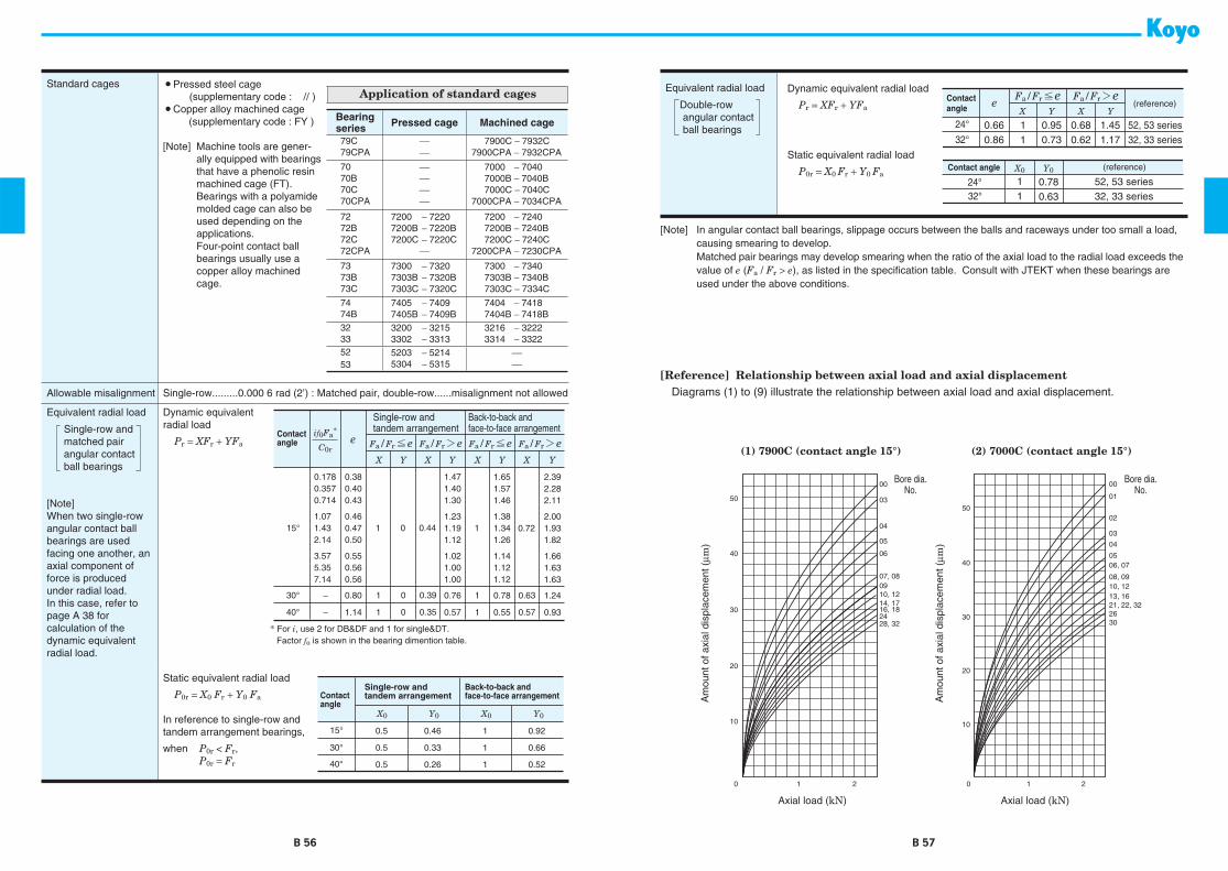
B 56 B 57
Standard cages *Pressed steel cage (supplementary code : // )
*Copper alloy machined cage (supplementary code : FY )
[Note] Machine tools are gener-ally equipped with bearings that have a phenolic resin machined cage (FT).Bearings with a polyamide molded cage can also be used depending on the applications.Four-point contact ball bearings usually use acopper alloy machined cage.
Application of standard cages
Bearingseries Pressed cage Machined cage
79C79CPA
⎯⎯
7900C − 7932C7900CPA − 7932CPA
7070B70C70CPA
⎯⎯⎯⎯
7000 − 70407000B − 7040B7000C − 7040C
7000CPA − 7034CPA
7272B72C72CPA
7200 − 72207200B − 7220B7200C − 7220C
⎯
7200 − 72407200B − 7240B7200C − 7240C
7200CPA − 7230CPA
7373B73C
7300 − 73207303B − 7320B7303C − 7320C
7300 − 73407303B − 7340B7303C − 7334C
7474B
7405 − 74097405B − 7409B
7404 − 74187404B − 7418B
3233
3200 − 32153302 − 3313
3216 − 32223314 − 3322
5253
5203 − 52145304 − 5315
⎯⎯
Allowable misalignment Single-row.........0.000 6 rad (2’) : Matched pair, double-row......misalignment not allowed
Equivalent radial load
Single-row andmatched pairangular contactball bearings
[Note]When two single-row angular contact ball bearings are usedfacing one another, an axial component of force is producedunder radial load.In this case, refer to page A 38 forcalculation of the dynamic equivalent radial load.
Dynamic equivalentradial load
Pr = XFr + YFa
−
−
YX YX YX YX
e Fa/Fr ² e Fa/Fr > e Fa/Fr > eFa/Fr ² e
Single-row andtandem arrangement
Back-to-back andface-to-face arrangementContact
angle
* For i, use 2 for DB&DF and 1 for single&DT. Factor fo is shown in the bearing dimention table.
if0Fa*
C0r
2.392.282.11
2.001.931.82
1.661.631.63
0.72
1.24
0.93
1.651.571.46
1.381.341.26
1.141.121.12
0.78
0.55
1.471.401.30
1.231.191.12
1.021.001.00
0.76
0.57
0.380.400.43
0.460.470.50
0.550.560.56
0.80
1.14
0.1780.3570.714
1.071.432.14
3.575.357.14
0.63
0.57
1
1
1
1
1
1
15°
30°
40°
0
0
0
0.44
0.39
0.35
Static equivalent radial load
P0r = X0 Fr + Y0 Fa
In reference to single-row andtandem arrangement bearings,
when P0r < Fr,P0r = Fr
X0 Y0 Y0X0
0.5
0.5
0.5
1
1
1
0.46
0.33
0.26
0.92
0.66
0.52
Single-row andtandem arrangement
Back-to-back andface-to-face arrangementContact
angle
30°
40°
15°
Equivalent radial load
Double-rowangular contactball bearings
Dynamic equivalent radial load
Pr = XFr + YFa
Static equivalent radial load
P0r = X0 Fr + Y0 Fa
32°
24° 0.660.86
0.950.73
0.680.62
1.451.17
52, 53 series32, 33 series
11
YX YXe Fa/Fr ² e Fa/Fr > e
32°24° 0.78
0.6352, 53 series32, 33 series
11
X0 Y0
Contactangle
Contact angle
(reference)
(reference)
[Note] In angular contact ball bearings, slippage occurs between the balls and raceways under too small a load, causing smearing to develop.Matched pair bearings may develop smearing when the ratio of the axial load to the radial load exceeds the value of e (Fa / Fr > e), as listed in the specification table. Consult with JTEKT when these bearings are used under the above conditions.
[Reference] Relationship between axial load and axial displacementDiagrams (1) to (9) illustrate the relationship between axial load and axial displacement.
00
50
40
30
20
10
0 1 2
01
02
03
04
0506, 07
08, 0910, 1213, 1621, 22, 322630
50
40
30
20
10
0 1 2
00
03
04
05
06
0907, 08
10, 1214, 1716, 182428, 32
Axial load (kN)
Bore dia.No.
Bore dia.No.
(1) 7900C (contact angle 15°) (2) 7000C (contact angle 15°)
Axial load (kN)
Am
ount
of a
xial
dis
plac
emen
t (μm
)
Am
ount
of a
xial
dis
plac
emen
t (μm
)

B 58 B 59
Axial load (kN)Axial load (kN)
Axial load (kN)
(3) 7200C (contact angle 15°)
(4) 7000 (contact angle 30°) (5) 7200 (contact angle 30°)
00
30
20
10
01
0203
0405060708,09101215,1618,19,2024
28,3026
0 10.5 1.5 2 2.5
0030
20
10
0 10.5 1.5 2 2.5
01
02
0304
05
07
0910,11
13,1417,1824,2632,34
60
50
40
302826,30
2417,18,2113,1512,1408,0905,06,070402,0301
00
20
10
0 1 2 2.5
Bore dia.No.
Bore dia.No.
Bore dia.No.
Am
ount
of a
xial
dis
plac
emen
t (μm
)A
mou
nt o
f axi
al d
ispl
acem
ent (
μm)
Am
ount
of a
xial
dis
plac
emen
t (μm
)
Axial load (kN) Axial load (kN)
(6) 7000B (contact angle 40°) (7) 7200B (contact angle 40°)
20
10
0 1 2
01
00
050607
08
04
0302
101215,1618,2022,24
2628
20
10
0 1 2
02
05
09
1213,1417,1820,2226
Am
ount
of a
xial
dis
plac
emen
t (μm
)
Am
ount
of a
xial
dis
plac
emen
t (μm
)
Bore dia.No.
Bore dia.No.

With machined cage With pressed cage
r1 r
r r1
ra
u Da u da
ra
a
r
r
u D u d
r1
r
B
Single-row angular contact ball bearings
Boundary dimensions Basic load ratings
(kN)
Fatigue load limits
(kN)
Factor Limiting speeds
1)
Bearing No.
2)
Loadcenter
(mm)
a
Mounting dimensions
(Refer.)
Mass
(kg)
(mm)
With machined cage
With pressed cage
C
u
(min
−
1
) (mm)
d D Br r
1
C
r
C
0r
C
r
C
0r
f
0
Grease lub. Oil lub.
d
a
D
a
r
a
min. min. min. max. max.
10
22 6 0.3 0.15 3.75 1.50
⎯ ⎯
0.060
⎯
14.2 52 000 69 000
7900C
5.1 12.5 19.5 0.3 0.008
10
26 8 0.3 0.15 6.25 2.35
⎯ ⎯
0.120
⎯ ⎯
34 000 42 000
7000
9.1 12.5 23.5 0.3 0.021
10
26 8 0.3 0.15 5.80 2.15
⎯ ⎯
0.110
⎯ ⎯
25 000 33 000
7000B
11.6 12.5 23.5 0.3 0.021
10
26 8 0.3 0.15 6.60 2.45
⎯ ⎯
0.130
⎯
12.5 47 000 62 000
7000C
6.4 12.5 23.5 0.3 0.021
10
30 9 0.6 0.3 5.85 2.20 6.75 2.75 0.110 0.140
⎯
29 000 37 000
7200
10.4 14.5 25.5 0.6 0.031
10
30 9 0.6 0.3 5.35 2.00 6.20 2.50 0.100 0.130
⎯
22 000 29 000
7200B
13.1 14.5 25.5 0.6 0.031
10
30 9 0.6 0.3 6.25 2.35 7.25 2.95 0.120 0.150 13.4 40 000 54 000
7200C
7.2 14.5 25.5 0.6 0.031
10
35 11 0.6 0.3 10.6 3.75 11.6 4.30 0.300 0.340
⎯
27 000 33 000
7300
12.0 14.5 30.5 0.6 0.054
12
24 6 0.3 0.15 4.00 1.70
⎯ ⎯
0.070
⎯
14.7 48 000 62 000
7901C
5.4 14.5 21.5 0.3 0.010
12
28 8 0.3 0.15 6.75 2.75
⎯ ⎯
0.140
⎯ ⎯
29 000 37 000
7001
9.9 14.5 25.5 0.3 0.024
12
28 8 0.3 0.15 6.20 2.50
⎯ ⎯
0.130
⎯ ⎯
22 000 29 000
7001B
12.6 14.5 25.5 0.3 0.024
12
28 8 0.3 0.15 7.25 2.95
⎯ ⎯
0.150
⎯
13.4 40 000 54 000
7001C
6.7 14.5 25.5 0.3 0.024
12
32 10 0.6 0.3 9.30 3.65 10.0 4.05 0.280 0.310
⎯
27 000 34 000
7201
11.4 16.5 27.5 0.6 0.038
12
32 10 0.6 0.3 8.65 3.40 9.30 3.75 0.240 0.270
⎯
20 000 27 000
7201B
14.2 16.5 27.5 0.6 0.038
12
32 10 0.6 0.3 9.90 3.85 10.6 4.30 0.300 0.330 12.5 38 000 50 000
7201C
7.9 16.5 27.5 0.6 0.038
12
37 12 1 0.6 12.8 4.60 14.0 5.25 0.360 0.410
⎯
24 000 31 000
7301
13.1 17.5 31.5 1 0.065
15
28 7 0.3 0.15 5.95 2.65
⎯ ⎯
0.110
⎯
14.5 39 000 52 000
7902C
6.4 17.5 25.5 0.3 0.015
15
32 9 0.3 0.15 7.65 3.45
⎯ ⎯
0.180
⎯ ⎯
26 000 32 000
7002
11.3 17.5 29.5 0.3 0.035
15
32 9 0.3 0.15 6.95 3.15
⎯ ⎯
0.160
⎯ ⎯
19 000 25 000
7002B
14.6 17.5 29.5 0.3 0.035
15
32 9 0.3 0.15 8.25 3.70
⎯ ⎯
0.190
⎯
14.1 35 000 47 000
7002C
7.6 17.5 29.5 0.3 0.035
15
35 11 0.6 0.3 10.1 4.25 10.1 4.25 0.300 0.300
⎯
24 000 29 000
7202
12.9 19.5 30.5 0.6 0.048
15
35 11 0.6 0.3 9.30 3.95 9.30 3.95 0.260 0.260
⎯
18 000 24 000
7202B
16.2 19.5 30.5 0.6 0.048
15
35 11 0.6 0.3 10.8 4.55 10.8 4.55 0.340 0.340 13.3 33 000 43 000
7202C
8.9 19.5 30.5 0.6 0.048
15
42 13 1 0.6 15.7 6.45 16.8 7.20 0.490 0.550
⎯
20 000 25 000
7302
15.0 20.5 36.5 1 0.088
17
30 7 0.3 0.15 6.25 2.95
⎯ ⎯
0.120
⎯
14.9 36 000 47 000
7903C
6.7 19.5 27.5 0.3 0.016
17
35 10 0.3 0.15 8.40 4.15
⎯ ⎯
0.210
⎯ ⎯
23 000 28 000
7003
12.7 19.5 32.5 0.3 0.045
[Notes] 1) Limiting speeds shown above are applicable to machined cage bearings.Limiting speeds of pressed cage bearings should be kept to under 80% of this value.For bearings with 15
°
contact angle, this figure is applied to the high precision bearings ranked higher thanclass 5, used with machined cage or molded cage.
2) B, C or no indication after the bearing number indicates nominal contact angle of 40
°
, 15
°
and30
°
respectively.[Remark] Standard cage types used for the above bearings are described earlier in this section.
With �machined cage
With �pressed cage
B 60 B 61
d
10
∼
(
17
)
mm

With machined cage With pressed cage
r1 r
r r1
ra
u Da u da
ra
a
r
r
u D u d
r1
r
B
Single-row angular contact ball bearings
17
35 10 0.3 0.15 7.60 3.75
⎯ ⎯
0.190
⎯ ⎯
17 000 23 000
7003B
16.1 19.5 32.5 0.3 0.045
17
35 10 0.3 0.15 9.15 4.45
⎯ ⎯
0.230
⎯
14.6 31 000 41 000
7003C
8.6 19.5 32.5 0.3 0.045
17
40 12 0.6 0.3 12.7 5.50 12.7 5.50 0.380 0.380
⎯
21 000 26 000
7203
14.4 21.5 35.5 0.6 0.070
17
40 12 0.6 0.3 11.7 5.05 11.7 5.05 0.330 0.330
⎯
16 000 21 000
7203B
18.2 21.5 35.5 0.6 0.070
17
40 12 0.6 0.3 13.6 5.90 13.6 5.90 0.440 0.440 13.4 29 000 38 000
7203C
9.9 21.5 35.5 0.6 0.070
17
47 14 1 0.6 18.7 7.90 20.0 8.75 0.590 0.660
⎯
18 000 23 000
7303
16.5 22.5 41.5 1 0.120
17
47 14 1 0.6 17.3 7.30 18.5 8.10 0.510 0.570
⎯
14 000 18 000
7303B
20.8 22.5 41.5 1 0.120
17
47 14 1 0.6 19.8 8.40 19.8 8.40 0.650 0.650 12.6 25 000 33 000
7303C
11.4 22.5 41.5 1 0.120
20
37 9 0.3 0.15 9.10 4.55
⎯ ⎯
0.240
⎯
14.9 30 000 39 000
7904C
8.3 22.5 34.5 0.3 0.035
20
42 12 0.6 0.3 12.9 6.10
⎯ ⎯
0.390
⎯ ⎯
19 000 24 000
7004
15.1 24.5 37.5 0.6 0.079
20
42 12 0.6 0.3 11.7 5.55
⎯ ⎯
0.340
⎯ ⎯
14 000 19 000
7004B
19.2 24.5 37.5 0.6 0.079
20
42 12 0.6 0.3 13.9 6.60
⎯ ⎯
0.450
⎯
14.1 26 000 35 000
7004C
10.2 24.5 37.5 0.6 0.079
20
47 14 1 0.6 18.1 8.40 19.2 9.15 0.580 0.640
⎯
17 000 22 000
7204
17.0 25.5 41.5 1 0.112
20
47 14 1 0.6 16.6 7.70 17.6 8.40 0.500 0.550
⎯
13 000 17 000
7204B
21.5 25.5 41.5 1 0.112
20
47 14 1 0.6 19.4 9.00 20.6 9.80 0.670 0.730 13.4 24 000 32 000
7204C
11.6 25.5 41.5 1 0.112
20
52 15 1.1 0.6 21.8 9.40 23.4 10.4 0.710 0.790
⎯
17 000 21 000
7304
17.9 27 45 1 0.150
20
52 15 1.1 0.6 20.2 8.70 21.7 9.65 0.610 0.680
⎯
13 000 17 000
7304B
22.6 27 45 1 0.150
20
52 15 1.1 0.6 23.1 9.95 24.8 11.1 0.780 0.860 12.6 23 000 31 000
7304C
12.3 27 45 1 0.150
20
72 19 1.1 0.6 44.5 19.1
⎯ ⎯
1.50
⎯ ⎯
9 600 13 000
7404
23.1 27 65 1 0.395
20
72 19 1.1 0.6 41.9 17.9
⎯ ⎯
1.40
⎯ ⎯
8 500 12 000
7404B
29.2 27 65 1 0.395
25
42 9 0.3 0.15 10.2 5.45
⎯ ⎯
0.300
⎯
15.5 25 000 33 000
7905C
9.1 27.5 39.5 0.3 0.041
25
47 12 0.6 0.3 14.1 7.40
⎯ ⎯
0.450
⎯ ⎯
17 000 21 000
7005
16.4 29.5 42.5 0.6 0.091
25
47 12 0.6 0.3 12.8 6.70
⎯ ⎯
0.390
⎯ ⎯
12 000 17 000
7005B
21.1 29.5 42.5 0.6 0.091
25
47 12 0.6 0.3 15.4 8.00
⎯ ⎯
0.510
⎯
14.7 23 000 30 000
7005C
10.8 29.5 42.5 0.6 0.091
25
52 15 1 0.6 19.2 9.50 20.2 10.3 0.620 0.670
⎯
15 000 19 000
7205
18.8 30.5 46.5 1 0.135
25
52 15 1 0.6 17.5 8.70 18.4 9.40 0.530 0.580
⎯
12 000 15 000
7205B 23.9 30.5 46.5 1 0.135
Boundary dimensions Basic load ratings (kN) Fatigue load limits (kN) Factor Limiting speeds 1)
Bearing No. 2)
Loadcenter(mm)
a
Mounting dimensions (Refer.)
Mass(kg)
(mm) With machined cage With pressed cage Cu (min−1) (mm)
d D Br r1 Cr C0r Cr C0r f 0 Grease lub. Oil lub.
da Da ra
min. min. min. max. max.
[Notes] 1) Limiting speeds shown above are applicable to machined cage bearings.Limiting speeds of pressed cage bearings should be kept to under 80% of this value.For bearings with 15° contact angle, this figure is applied to the high precision bearings ranked higher thanclass 5, used with machined cage or molded cage.
2) B, C or no indication after the bearing number indicates nominal contact angle of 40°, 15° and30° respectively.
[Remark] Standard cage types used for the above bearings are described earlier in this section.
With �machined cage
With �pressed cage
B 62 B 63
d (17) ∼ (25) mm

With machined cage With pressed cage
r1 r
r r1
ra
u Da u da
ra
a
r
r
u D u d
r1
r
B
Single-row angular contact ball bearings
25 52 15 1 0.6 20.7 10.2 21.9 11.1 0.710 0.770 14.0 21 000 28 000 7205C 12.7 30.5 46.5 1 0.13525 62 17 1.1 0.6 31.0 14.4 33.0 15.8 1.05 1.15 ⎯ 14 000 17 000 7305 21.1 32 55 1 0.24325 62 17 1.1 0.6 28.6 13.3 30.5 14.6 0.910 1.00 ⎯ 10 000 14 000 7305B 26.8 32 55 1 0.243
25 62 17 1.1 0.6 33.0 15.3 35.1 16.8 1.20 1.30 12.8 19 000 25 000 7305C 14.3 32 55 1 0.24325 80 21 1.5 1 49.7 23.2 53.3 25.7 1.80 2.00 ⎯ 8 200 11 000 7405 26.4 33.5 71.5 1.5 0.52725 80 21 1.5 1 46.1 21.5 49.5 23.9 1.55 1.70 ⎯ 7 300 10 000 7405B 33.6 33.5 71.5 1.5 0.527
30 47 9 0.3 0.15 10.4 6.25 ⎯ ⎯ 0.320 ⎯ 15.9 22 000 29 000 7906C 9.7 32.5 44.5 0.3 0.04630 55 13 1 0.6 18.2 10.1 ⎯ ⎯ 0.610 ⎯ ⎯ 14 000 18 000 7006 18.8 35.5 49.5 1 0.13330 55 13 1 0.6 16.4 9.20 ⎯ ⎯ 0.530 ⎯ ⎯ 11 000 14 000 7006B 24.3 35.5 49.5 1 0.133
30 55 13 1 0.6 19.8 11.0 ⎯ ⎯ 0.690 ⎯ 14.9 20 000 26 000 7006C 12.2 35.5 49.5 1 0.13330 62 16 1 0.6 26.7 13.7 28.1 14.8 0.890 0.970 ⎯ 13 000 16 000 7206 21.5 35.5 56.5 1 0.20830 62 16 1 0.6 24.3 12.5 25.6 13.6 0.770 0.840 ⎯ 9 600 13 000 7206B 27.6 35.5 56.5 1 0.208
30 62 16 1 0.6 28.8 14.7 30.4 16.0 1.00 1.10 14.0 18 000 24 000 7206C 14.3 35.5 56.5 1 0.20830 72 19 1.1 0.6 37.6 18.9 39.9 20.6 1.30 1.45 ⎯ 12 000 14 000 7306 24.5 37 65 1 0.36230 72 19 1.1 0.6 34.5 17.4 36.6 19.0 1.15 1.25 ⎯ 8 700 12 000 7306B 31.3 37 65 1 0.362
30 72 19 1.1 0.6 40.4 20.3 42.8 22.1 1.50 1.65 13.4 16 000 21 000 7306C 16.5 37 65 1 0.36230 90 23 1.5 1 59.5 28.4 63.9 31.6 2.20 2.45 ⎯ 7 300 9 700 7406 29.3 38.5 81.5 1.5 0.68630 90 23 1.5 1 55.2 26.4 59.3 29.3 1.90 2.10 ⎯ 6 500 8 900 7406B 37.3 38.5 81.5 1.5 0.686
35 55 10 0.6 0.3 15.7 9.70 ⎯ ⎯ 0.550 ⎯ 15.7 19 000 25 000 7907C 11.0 39.5 50.5 0.6 0.07435 62 14 1 0.6 21.9 12.6 ⎯ ⎯ 0.740 ⎯ ⎯ 12 000 15 000 7007 21.2 40.5 56.5 1 0.17035 62 14 1 0.6 19.7 11.4 ⎯ ⎯ 0.640 ⎯ ⎯ 9 200 12 000 7007B 27.6 40.5 56.5 1 0.170
35 62 14 1 0.6 23.9 13.7 ⎯ ⎯ 0.840 ⎯ 15.0 17 000 22 000 7007C 13.5 40.5 56.5 1 0.17035 72 17 1.1 0.6 35.2 18.6 37.1 20.2 1.20 1.30 ⎯ 11 000 14 000 7207 24.2 42 65 1 0.29535 72 17 1.1 0.6 32.0 17.0 33.8 18.5 1.05 1.15 ⎯ 8 300 11 000 7207B 31.4 42 65 1 0.295
35 72 17 1.1 0.6 38.0 20.1 40.1 21.7 1.40 1.50 14.0 15 000 20 000 7207C 15.8 42 65 1 0.29535 80 21 1.5 1 44.2 22.0 49.9 26.4 1.55 1.85 ⎯ 10 000 13 000 7307 27.4 43.5 71.5 1.5 0.47535 80 21 1.5 1 40.6 20.2 45.8 24.3 1.30 1.60 ⎯ 7 700 10 000 7307B 35.0 43.5 71.5 1.5 0.475
Boundary dimensions Basic load ratings (kN) Fatigue load limits (kN) Factor Limiting speeds 1)
Bearing No. 2)
Loadcenter(mm)
a
Mounting dimensions (Refer.)
Mass(kg)
(mm) With machined cage With pressed cage Cu (min−1) (mm)
d D Br r1 Cr C0r Cr C0r f 0 Grease lub. Oil lub.
da Da ra
min. min. min. max. max.
[Notes] 1) Limiting speeds shown above are applicable to machined cage bearings.Limiting speeds of pressed cage bearings should be kept to under 80% of this value.For bearings with 15° contact angle, this figure is applied to the high precision bearings ranked higher thanclass 5, used with machined cage or molded cage.
2) B, C or no indication after the bearing number indicates nominal contact angle of 40°, 15° and30° respectively.
[Remark] Standard cage types used for the above bearings are described earlier in this section.
With �machined cage
With �pressed cage
B 64 B 65
d (25) ∼ (35) mm

With machined cage With pressed cage
r1 r
r r1
ra
u Da u da
ra
a
r
r
u D u d
r1
r
B
Single-row angular contact ball bearings
35 80 21 1.5 1 47.4 23.6 53.5 28.3 1.75 2.10 13.4 14 000 19 000 7307C 18.3 43.5 71.5 1.5 0.47535 100 25 1.5 1 75.6 37.0 81.1 41.1 2.85 3.20 ⎯ 6 500 8 600 7407 32.6 43.5 91.5 1.5 0.95035 100 25 1.5 1 70.2 34.3 75.3 38.1 2.45 2.75 ⎯ 5 700 7 900 7407B 41.7 43.5 91.5 1.5 0.950
40 62 12 0.6 0.3 19.7 12.4 ⎯ ⎯ 0.710 ⎯ 15.7 17 000 22 000 7908C 12.8 44.5 57.5 0.6 0.10740 68 15 1 0.6 23.4 14.6 ⎯ ⎯ 0.830 ⎯ ⎯ 11 000 14 000 7008 23.2 45.5 62.5 1 0.21040 68 15 1 0.6 21.1 13.2 ⎯ ⎯ 0.720 ⎯ ⎯ 8 300 11 000 7008B 30.2 45.5 62.5 1 0.210
40 68 15 1 0.6 25.7 15.9 ⎯ ⎯ 0.940 ⎯ 15.4 15 000 20 000 7008C 14.8 45.5 62.5 1 0.21040 80 18 1.1 0.6 42.0 23.3 44.1 25.1 1.50 1.60 ⎯ 10 000 12 000 7208 26.3 47 73 1 0.38240 80 18 1.1 0.6 38.2 21.3 40.2 23.0 1.30 1.40 ⎯ 7 500 10 000 7208B 34.2 47 73 1 0.382
40 80 18 1.1 0.6 45.4 25.2 47.7 27.1 1.70 1.85 14.2 14 000 18 000 7208C 17.0 47 73 1 0.38240 90 23 1.5 1 54.0 27.4 61.0 32.9 1.90 2.30 ⎯ 9 200 12 000 7308 30.3 48.5 81.5 1.5 0.65740 90 23 1.5 1 49.6 25.2 56.0 30.3 1.65 2.00 ⎯ 6 900 9 200 7308B 38.8 48.5 81.5 1.5 0.657
40 90 23 1.5 1 57.9 29.4 65.4 35.3 2.20 2.65 13.4 13 000 17 000 7308C 20.2 48.5 81.5 1.5 0.65740 110 27 2 1 87.4 43.5 93.8 48.4 3.35 3.70 ⎯ 5 900 7 900 7408 35.5 50 100 2 1.2340 110 27 2 1 81.1 40.4 87.0 44.9 2.90 3.20 ⎯ 5 200 7 200 7408B 45.4 50 100 2 1.23
45 68 12 0.6 0.3 20.8 14.1 ⎯ ⎯ 0.770 ⎯ 16.0 15 000 20 000 7909C 13.6 49.5 63.5 0.6 0.12745 75 16 1 0.6 27.8 17.7 ⎯ ⎯ 1.00 ⎯ ⎯ 10 000 12 000 7009 25.3 50.5 69.5 1 0.26045 75 16 1 0.6 25.0 16.0 ⎯ ⎯ 0.870 ⎯ ⎯ 7 500 10 000 7009B 33.2 50.5 69.5 1 0.260
45 75 16 1 0.6 30.5 19.3 ⎯ ⎯ 1.15 ⎯ 15.4 14 000 18 000 7009C 16.0 50.5 69.5 1 0.26045 85 19 1.1 0.6 47.2 26.6 49.6 28.6 1.70 1.85 ⎯ 9 400 12 000 7209 28.0 52 78 1 0.43045 85 19 1.1 0.6 42.9 24.3 45.1 26.1 1.50 1.60 ⎯ 7 000 9 400 7209B 36.4 52 78 1 0.430
45 85 19 1.1 0.6 51.0 28.7 53.6 30.9 1.95 2.10 14.2 13 000 17 000 7209C 18.1 52 78 1 0.43045 100 25 1.5 1 68.9 37.1 73.1 40.4 2.55 2.80 ⎯ 8 200 10 000 7309 33.6 53.5 91.5 1.5 0.87545 100 25 1.5 1 63.2 34.1 67.0 37.2 2.20 2.40 ⎯ 6 200 8 200 7309B 43.1 53.5 91.5 1.5 0.875
45 100 25 1.5 1 74.0 39.7 78.4 43.4 2.95 3.20 13.5 11 000 15 000 7309C 22.3 53.5 91.5 1.5 0.87545 120 29 2 1 106 53.8 114 59.8 4.20 4.65 ⎯ 5 400 7 100 7409 38.6 55 110 2 1.5545 120 29 2 1 98.7 50.0 106 55.5 3.60 4.00 ⎯ 4 800 6 600 7409B 49.5 55 110 2 1.55
Boundary dimensions Basic load ratings (kN) Fatigue load limits (kN) Factor Limiting speeds 1)
Bearing No. 2)
Loadcenter(mm)
a
Mounting dimensions (Refer.)
Mass(kg)
(mm) With machined cage With pressed cage Cu (min−1) (mm)
d D Br r1 Cr C0r Cr C0r f 0 Grease lub. Oil lub.
da Da ra
min. min. min. max. max.
[Notes] 1) Limiting speeds shown above are applicable to machined cage bearings.Limiting speeds of pressed cage bearings should be kept to under 80% of this value.For bearings with 15° contact angle, this figure is applied to the high precision bearings ranked higher thanclass 5, used with machined cage or molded cage.
2) B, C or no indication after the bearing number indicates nominal contact angle of 40°, 15° and30° respectively.
[Remark] Standard cage types used for the above bearings are described earlier in this section.
With �machined cage
With �pressed cage
B 66 B 67
d (35) ∼ 45 mm

With machined cage With pressed cage
r1 r
r r1
ra
u Da u da
ra
a
r
r
u D u d
r1
r
B
Single-row angular contact ball bearings
50 72 12 0.6 0.3 21.8 15.7 ⎯ ⎯ 0.840 ⎯ 16.2 14 000 18 000 7910C 14.2 54.5 67.5 0.6 0.12850 80 16 1 0.6 29.5 20.1 ⎯ ⎯ 1.10 ⎯ ⎯ 9 200 11 000 7010 26.9 55.5 74.5 1 0.29050 80 16 1 0.6 26.5 18.1 ⎯ ⎯ 0.960 ⎯ ⎯ 6 900 9 200 7010B 35.3 55.5 74.5 1 0.290
50 80 16 1 0.6 32.5 21.9 ⎯ ⎯ 1.25 ⎯ 15.7 13 000 17 000 7010C 16.8 55.5 74.5 1 0.29050 90 20 1.1 0.6 49.2 29.4 51.6 31.5 1.80 1.95 ⎯ 8 500 11 000 7210 30.4 57 83 1 0.48550 90 20 1.1 0.6 44.6 26.7 46.7 28.6 1.55 1.70 ⎯ 6 400 8 500 7210B 39.6 57 83 1 0.485
50 90 20 1.1 0.6 53.5 31.8 56.0 34.1 2.05 2.20 14.6 12 000 16 000 7210C 19.4 57 83 1 0.48550 110 27 2 1 87.6 48.1 92.9 52.5 3.35 3.65 ⎯ 7 300 9 100 7310 37.2 60 100 2 1.1450 110 27 2 1 80.5 44.3 85.3 48.3 2.90 3.15 ⎯ 5 500 7 300 7310B 47.9 60 100 2 1.14
50 110 27 2 1 93.9 51.6 99.5 56.2 3.85 4.20 13.4 10 000 13 000 7310C 24.5 60 100 2 1.1450 130 31 2.1 1.1 122 65.3 ⎯ ⎯ 4.90 ⎯ ⎯ 4 900 6 600 7410 41.6 62 118 2 1.9250 130 31 2.1 1.1 113 60.4 ⎯ ⎯ 4.20 ⎯ ⎯ 4 400 6 000 7410B 53.5 62 118 2 1.92
55 80 13 1 0.6 24.6 18.5 ⎯ ⎯ 0.980 ⎯ 16.3 13 000 17 000 7911C 15.5 60.5 74.5 1 0.17855 90 18 1.1 0.6 38.9 26.3 ⎯ ⎯ 1.50 ⎯ ⎯ 8 300 10 000 7011 29.9 62 83 1 0.42055 90 18 1.1 0.6 34.9 23.7 ⎯ ⎯ 1.30 ⎯ ⎯ 6 200 8 300 7011B 39.4 62 83 1 0.420
55 90 18 1.1 0.6 42.6 28.6 ⎯ ⎯ 1.65 ⎯ 15.5 11 000 15 000 7011C 18.7 62 83 1 0.42055 100 21 1.5 1 60.9 37.1 63.7 39.8 2.30 2.45 ⎯ 7 600 9 500 7211 33.3 63.5 91.5 1.5 0.63555 100 21 1.5 1 55.1 33.8 57.7 36.2 2.00 2.15 ⎯ 5 700 7 600 7211B 43.6 63.5 91.5 1.5 0.635
55 100 21 1.5 1 66.1 40.2 69.2 43.1 2.60 2.80 14.6 11 000 14 000 7211C 21.1 63.5 91.5 1.5 0.63555 120 29 2 1 101 56.5 107 61.7 3.95 4.30 ⎯ 6 700 8 400 7311 40.2 65 110 2 1.4555 120 29 2 1 92.9 52.0 98.4 56.7 3.40 3.70 ⎯ 5 000 6 700 7311B 51.8 65 110 2 1.45
55 120 29 2 1 108 60.6 115 66.1 4.50 4.90 13.4 9 300 12 000 7311C 26.4 65 110 2 1.4555 140 33 2.1 1.1 148 82.4 ⎯ ⎯ 6.40 ⎯ ⎯ 4 500 6 000 7411 45.0 67 128 2 2.3655 140 33 2.1 1.1 138 76.5 ⎯ ⎯ 5.50 ⎯ ⎯ 4 000 5 500 7411B 57.8 67 128 2 2.36
60 85 13 1 0.6 29.0 21.8 ⎯ ⎯ 1.15 ⎯ 16.3 12 000 16 000 7912C 16.3 65.5 79.5 1 0.18760 95 18 1.1 0.6 39.9 28.1 ⎯ ⎯ 1.55 ⎯ ⎯ 7 700 9 700 7012 31.4 67 88 1 0.45060 95 18 1.1 0.6 35.7 25.3 ⎯ ⎯ 1.35 ⎯ ⎯ 5 800 7 700 7012B 41.5 67 88 1 0.450
Boundary dimensions Basic load ratings (kN) Fatigue load limits (kN) Factor Limiting speeds 1)
Bearing No. 2)
Loadcenter(mm)
a
Mounting dimensions (Refer.)
Mass(kg)
(mm) With machined cage With pressed cage Cu (min−1) (mm)
d D Br r1 Cr C0r Cr C0r f 0 Grease lub. Oil lub.
da Da ra
min. min. min. max. max.
[Notes] 1) Limiting speeds shown above are applicable to machined cage bearings.Limiting speeds of pressed cage bearings should be kept to under 80% of this value.For bearings with 15° contact angle, this figure is applied to the high precision bearings ranked higher thanclass 5, used with machined cage or molded cage.
2) B, C or no indication after the bearing number indicates nominal contact angle of 40°, 15° and30° respectively.
[Remark] Standard cage types used for the above bearings are described earlier in this section.
With �machined cage
With �pressed cage
B 68 B 69
d 50 ∼ (60) mm

With machined cage With pressed cage
r1 r
r r1
ra
u Da u da
ra
a
r
r
u D u d
r1
r
B
Single-row angular contact ball bearings
60 95 18 1.1 0.6 43.8 30.6 ⎯ ⎯ 1.75 ⎯ 15.7 11 000 14 000 7012C 19.4 67 88 1 0.45060 110 22 1.5 1 73.7 45.7 77.1 49.0 2.85 3.05 ⎯ 6 900 8 600 7212 36.1 68.5 101.5 1.5 0.82060 110 22 1.5 1 66.8 41.6 69.9 44.6 2.45 2.60 ⎯ 5 100 6 900 7212B 47.5 68.5 101.5 1.5 0.820
60 110 22 1.5 1 80.0 49.5 83.8 53.0 3.20 3.45 14.5 9 500 13 000 7212C 22.7 68.5 101.5 1.5 0.82060 130 31 2.1 1.1 116 65.6 123 71.6 4.55 5.00 ⎯ 6 200 7 700 7312 43.2 72 118 2 1.8160 130 31 2.1 1.1 106 60.3 113 65.8 3.95 4.30 ⎯ 4 600 6 200 7312B 55.8 72 118 2 1.81
60 130 31 2.1 1.1 124 70.3 131 76.7 5.25 5.70 13.4 8 600 11 000 7312C 28.4 72 118 2 1.8160 150 35 2.1 1.1 161 93.6 ⎯ ⎯ 6.85 ⎯ ⎯ 4 100 5 500 7412 48.5 72 138 2 2.8560 150 35 2.1 1.1 149 86.7 ⎯ ⎯ 5.90 ⎯ ⎯ 3 700 5 100 7412B 62.6 72 138 2 2.85
65 90 13 1 0.6 25.9 21.2 ⎯ ⎯ 1.10 ⎯ 16.5 11 000 15 000 7913C 16.9 70.5 84.5 1 0.20565 100 18 1.1 0.6 42.1 31.4 ⎯ ⎯ 1.70 ⎯ ⎯ 7 200 9 000 7013 33.0 72 93 1 0.47065 100 18 1.1 0.6 37.7 28.3 ⎯ ⎯ 1.45 ⎯ ⎯ 5 400 7 200 7013B 43.8 72 93 1 0.470
65 100 18 1.1 0.6 46.3 34.3 ⎯ ⎯ 1.90 ⎯ 15.9 10 000 13 000 7013C 20.1 72 93 1 0.47065 120 23 1.5 1 84.1 54.2 87.8 57.8 3.35 3.55 ⎯ 6 400 8 000 7213 38.2 73.5 111.5 1.5 1.0265 120 23 1.5 1 76.2 49.3 79.5 52.6 2.90 3.10 ⎯ 4 800 6 400 7213B 50.3 73.5 111.5 1.5 1.02
65 120 23 1.5 1 91.4 58.7 95.4 62.6 3.80 4.05 14.6 8 900 12 000 7213C 23.9 73.5 111.5 1.5 1.0265 140 33 2.1 1.1 131 75.3 139 82.2 5.15 5.65 ⎯ 5 800 7 200 7313 46.3 77 128 2 2.2265 140 33 2.1 1.1 120 69.3 127 75.6 4.45 4.85 ⎯ 4 300 5 800 7313B 59.7 77 128 2 2.22
65 140 33 2.1 1.1 140 80.7 149 88.1 5.90 6.45 13.4 8 000 11 000 7313C 30.3 77 128 2 2.2265 160 37 2.1 1.1 174 104 ⎯ ⎯ 7.40 ⎯ ⎯ 3 900 5 200 7413 51.4 77 148 2 3.4165 160 37 2.1 1.1 161 96.8 ⎯ ⎯ 6.35 ⎯ ⎯ 3 500 4 800 7413B 66.3 77 148 2 3.41
70 100 16 1 0.6 36.2 29.0 ⎯ ⎯ 1.55 ⎯ 16.4 10 000 12 000 7914C 19.4 75.5 94.5 1 0.33270 110 20 1.1 0.6 53.3 39.4 ⎯ ⎯ 2.15 ⎯ ⎯ 6 600 8 300 7014 36.0 77 103 1 0.66070 110 20 1.1 0.6 47.8 35.5 ⎯ ⎯ 1.90 ⎯ ⎯ 5 000 6 600 7014B 47.8 77 103 1 0.660
70 110 20 1.1 0.6 58.6 43.0 ⎯ ⎯ 2.45 ⎯ 15.7 9 200 12 000 7014C 22.1 77 103 1 0.66070 125 24 1.5 1 87.3 55.6 95.4 63.5 3.40 3.90 ⎯ 6 100 7 600 7214 40.2 78.5 116.5 1.5 1.1270 125 24 1.5 1 79.0 50.6 86.4 57.8 2.95 3.40 ⎯ 4 600 6 100 7214B 52.9 78.5 116.5 1.5 1.12
Boundary dimensions Basic load ratings (kN) Fatigue load limits (kN) Factor Limiting speeds 1)
Bearing No. 2)
Loadcenter(mm)
a
Mounting dimensions (Refer.)
Mass(kg)
(mm) With machined cage With pressed cage Cu (min−1) (mm)
d D Br r1 Cr C0r Cr C0r f 0 Grease lub. Oil lub.
da Da ra
min. min. min. max. max.
[Notes] 1) Limiting speeds shown above are applicable to machined cage bearings.Limiting speeds of pressed cage bearings should be kept to under 80% of this value.For bearings with 15° contact angle, this figure is applied to the high precision bearings ranked higher thanclass 5, used with machined cage or molded cage.
2) B, C or no indication after the bearing number indicates nominal contact angle of 40°, 15° and30° respectively.
[Remark] Standard cage types used for the above bearings are described earlier in this section.
With �machined cage
With �pressed cage
B 70 B 71
d (60) ∼ (70) mm

With machined cage With pressed cage
r1 r
r r1
ra
u Da u da
ra
a
r
r
u D u d
r1
r
B
Single-row angular contact ball bearings
70 125 24 1.5 1 94.9 60.2 104 68.8 3.90 4.45 14.6 8 400 11 000 7214C 25.1 78.5 116.5 1.5 1.1270 150 35 2.1 1.1 147 85.8 156 93.6 5.70 6.20 ⎯ 5 400 6 700 7314 49.3 82 138 2 2.7070 150 35 2.1 1.1 135 78.9 143 86.0 4.90 5.35 ⎯ 4 000 5 400 7314B 63.7 82 138 2 2.70
70 150 35 2.1 1.1 158 91.9 167 100 6.50 7.10 13.4 7 500 9 900 7314C 32.2 82 138 2 2.7070 180 42 3 1.1 187 115 ⎯ ⎯ 5.30 ⎯ ⎯ 3 500 4 600 7414 57.6 84 166 2.5 4.9970 180 42 3 1.1 185 119 ⎯ ⎯ 5.45 ⎯ ⎯ 3 100 4 300 7414B 74.2 84 166 2.5 4.99
75 105 16 1 0.6 36.7 30.5 ⎯ ⎯ 1.60 ⎯ 16.5 9 300 12 000 7915C 20.1 80.5 99.5 1 0.35075 115 20 1.1 0.6 54.6 41.7 ⎯ ⎯ 2.25 ⎯ ⎯ 6 300 7 800 7015 37.4 82 108 1 0.69075 115 20 1.1 0.6 48.8 37.6 ⎯ ⎯ 1.95 ⎯ ⎯ 4 700 6 300 7015B 49.9 82 108 1 0.690
75 115 20 1.1 0.6 60.1 45.6 ⎯ ⎯ 2.55 ⎯ 15.9 8 700 11 000 7015C 22.7 82 108 1 0.69075 130 25 1.5 1 99.0 65.2 103 69.5 3.95 4.20 ⎯ 5 800 7 200 7215 42.1 83.5 121.5 1.5 1.2375 130 25 1.5 1 89.6 59.3 93.6 63.3 3.40 3.65 ⎯ 4 300 5 800 7215B 55.5 83.5 121.5 1.5 1.23
75 130 25 1.5 1 108 70.6 112 75.3 4.50 4.80 14.6 8 000 11 000 7215C 26.2 83.5 121.5 1.5 1.2375 160 37 2.1 1.1 160 97.0 170 106 6.20 6.75 ⎯ 5 000 6 300 7315 52.4 87 148 2 3.1575 160 37 2.1 1.1 147 89.2 156 97.3 5.35 5.85 ⎯ 3 800 5 000 7315B 67.8 87 148 2 3.15
75 160 37 2.1 1.1 172 104 182 113 7.10 7.75 13.4 7 000 9 200 7315C 34.2 87 148 2 3.1575 190 45 3 1.1 214 141 ⎯ ⎯ 6.30 ⎯ ⎯ 3 300 4 400 7415 61.3 89 176 2.5 5.9075 190 45 3 1.1 198 131 ⎯ ⎯ 5.80 ⎯ ⎯ 2 900 4 000 7415B 78.9 89 176 2.5 5.90
80 110 16 1 0.6 37.3 31.6 ⎯ ⎯ 1.65 ⎯ 16.5 8 800 11 000 7916C 20.7 85.5 104.5 1 0.36880 125 22 1.1 0.6 66.7 50.6 ⎯ ⎯ 2.75 ⎯ ⎯ 5 800 7 200 7016 40.6 87 118 1 0.93080 125 22 1.1 0.6 59.8 45.7 ⎯ ⎯ 2.40 ⎯ ⎯ 4 300 5 800 7016B 54.0 87 118 1 0.930
80 125 22 1.1 0.6 73.3 55.3 ⎯ ⎯ 3.10 ⎯ 15.7 8 000 11 000 7016C 24.7 87 118 1 0.93080 140 26 2 1 107 71.5 111 76.2 4.10 4.40 ⎯ 5 400 6 700 7216 44.8 90 130 2 1.5080 140 26 2 1 96.4 65.0 101 69.3 3.55 3.80 ⎯ 4 000 5 400 7216B 59.2 90 130 2 1.50
80 140 26 2 1 116 77.5 121 82.7 4.70 5.00 14.7 7 500 9 900 7216C 27.7 90 130 2 1.5080 170 39 2.1 1.1 174 109 184 119 6.75 7.35 ⎯ 4 700 5 900 7316 55.6 92 158 2 3.8580 170 39 2.1 1.1 159 100 169 109 5.80 6.35 ⎯ 3 500 4 700 7316B 71.9 92 158 2 3.85
Boundary dimensions Basic load ratings (kN) Fatigue load limits (kN) Factor Limiting speeds 1)
Bearing No. 2)
Loadcenter(mm)
a
Mounting dimensions (Refer.)
Mass(kg)
(mm) With machined cage With pressed cage Cu (min−1) (mm)
d D Br r1 Cr C0r Cr C0r f 0 Grease lub. Oil lub.
da Da ra
min. min. min. max. max.
[Notes] 1) Limiting speeds shown above are applicable to machined cage bearings.Limiting speeds of pressed cage bearings should be kept to under 80% of this value.For bearings with 15° contact angle, this figure is applied to the high precision bearings ranked higher thanclass 5, used with machined cage or molded cage.
2) B, C or no indication after the bearing number indicates nominal contact angle of 40°, 15° and30° respectively.
[Remark] Standard cage types used for the above bearings are described earlier in this section.
With �machined cage
With �pressed cage
B 72 B 73
d (70) ∼ (80) mm

With machined cage With pressed cage
r1 r
r r1
ra
u Da u da
ra
a
r
r
u D u d
r1
r
B
Single-row angular contact ball bearings
80 170 39 2.1 1.1 186 117 197 127 7.70 8.40 13.5 6 500 8 600 7316C 36.2 92 158 2 3.8580 200 48 3 1.1 241 166 ⎯ ⎯ 7.20 ⎯ ⎯ 3 100 4 100 7416 65.0 94 186 2.5 6.0080 200 48 3 1.1 223 154 ⎯ ⎯ 6.65 ⎯ ⎯ 2 700 3 800 7416B 83.6 94 186 2.5 6.00
85 120 18 1.1 0.6 48.6 40.6 ⎯ ⎯ 2.10 ⎯ 16.5 8 100 11 000 7917C 22.7 92 113 1 0.52385 130 22 1.1 0.6 68.2 53.7 ⎯ ⎯ 2.75 ⎯ ⎯ 5 500 6 800 7017 42.3 92 123 1 0.97085 130 22 1.1 0.6 61.0 48.4 ⎯ ⎯ 2.40 ⎯ ⎯ 4 100 5 500 7017B 56.5 92 123 1 0.970
85 130 22 1.1 0.6 75.1 58.7 ⎯ ⎯ 3.15 ⎯ 15.9 7 600 10 000 7017C 25.5 92 123 1 0.97085 150 28 2 1 123 83.6 129 89.2 4.70 5.00 ⎯ 5 000 6 300 7217 47.9 95 140 2 1.8785 150 28 2 1 111 76.0 116 81.1 4.05 4.35 ⎯ 3 800 5 000 7217B 63.3 95 140 2 1.87
85 150 28 2 1 134 90.6 140 96.6 5.35 5.70 14.7 7 000 9 200 7217C 29.7 95 140 2 1.8785 180 41 3 1.1 187 122 198 133 7.30 7.95 ⎯ 4 400 5 500 7317 58.8 99 166 2.5 4.5385 180 41 3 1.1 172 112 182 122 6.30 6.85 ⎯ 3 300 4 400 7317B 76.1 99 166 2.5 4.53
85 180 41 3 1.1 201 130 213 142 8.35 9.10 13.5 6 100 8 100 7317C 38.3 99 166 2.5 4.5385 210 52 4 1.5 255 180 ⎯ ⎯ 7.65 ⎯ ⎯ 3 000 3 900 7417 68.7 103 192 3 8.5485 210 52 4 1.5 236 167 ⎯ ⎯ 7.10 ⎯ ⎯ 2 600 3 600 7417B 88.1 103 192 3 8.54
90 125 18 1.1 0.6 49.5 42.6 ⎯ ⎯ 2.15 ⎯ 16.6 7 800 10 000 7918C 23.4 97 118 1 0.55190 140 24 1.5 1 81.5 63.3 ⎯ ⎯ 3.25 ⎯ ⎯ 5 100 6 400 7018 45.2 98.5 131.5 1.5 1.2690 140 24 1.5 1 73.0 57.1 ⎯ ⎯ 2.80 ⎯ ⎯ 3 900 5 100 7018B 60.2 98.5 131.5 1.5 1.26
90 140 24 1.5 1 89.6 69.1 ⎯ ⎯ 3.65 ⎯ 15.7 7 100 9 400 7018C 27.4 98.5 131.5 1.5 1.2690 160 30 2 1 141 96.7 147 103 5.30 5.65 ⎯ 4 700 5 900 7218 51.1 100 150 2 2.3090 160 30 2 1 128 88.0 133 93.8 4.60 4.90 ⎯ 3 500 4 700 7218B 67.4 100 150 2 2.30
90 160 30 2 1 153 105 160 112 6.00 6.40 14.6 6 500 8 600 7218C 31.7 100 150 2 2.3090 190 43 3 1.1 201 135 213 147 5.90 6.40 ⎯ 4 200 5 200 7318 61.9 104 176 2.5 5.3090 190 43 3 1.1 184 124 195 135 5.40 5.90 ⎯ 3 100 4 200 7318B 80.2 104 176 2.5 5.30
90 190 43 3 1.1 216 145 229 158 6.30 6.90 13.5 5 800 7 700 7318C 40.3 104 176 2.5 5.3090 225 54 4 1.5 270 196 ⎯ ⎯ 8.10 ⎯ ⎯ 2 800 3 700 7418 72.5 108 207 3 11.490 225 54 4 1.5 250 182 ⎯ ⎯ 7.50 ⎯ ⎯ 2 500 3 400 7418B 93.1 108 207 3 11.4
Boundary dimensions Basic load ratings (kN) Fatigue load limits (kN) Factor Limiting speeds 1)
Bearing No. 2)
Loadcenter(mm)
a
Mounting dimensions (Refer.)
Mass(kg)
(mm) With machined cage With pressed cage Cu (min−1) (mm)
d D Br r1 Cr C0r Cr C0r f 0 Grease lub. Oil lub.
da Da ra
min. min. min. max. max.
[Notes] 1) Limiting speeds shown above are applicable to machined cage bearings.Limiting speeds of pressed cage bearings should be kept to under 80% of this value.For bearings with 15° contact angle, this figure is applied to the high precision bearings ranked higher thanclass 5, used with machined cage or molded cage.
2) B, C or no indication after the bearing number indicates nominal contact angle of 40°, 15° and30° respectively.
[Remark] Standard cage types used for the above bearings are described earlier in this section.
With �machined cage
With �pressed cage
B 74 B 75
d (80) ∼ 90 mm
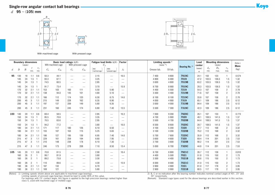
With machined cage With pressed cage
r1 r
r r1
ra
u Da u da
ra
a
r
r
u D u d
r1
r
B
Single-row angular contact ball bearings
95 130 18 1.1 0.6 50.3 44.1 ⎯ ⎯ 2.15 ⎯ 16.5 7 400 9 800 7919C 24.1 102 123 1 0.57495 145 24 1.5 1 83.3 67.1 ⎯ ⎯ 3.25 ⎯ ⎯ 4 800 6 000 7019 47.2 103.5 136.5 1.5 1.3295 145 24 1.5 1 74.5 60.5 ⎯ ⎯ 2.85 ⎯ ⎯ 3 600 4 800 7019B 63.2 103.5 136.5 1.5 1.32
95 145 24 1.5 1 91.7 73.4 ⎯ ⎯ 3.70 ⎯ 15.9 6 700 8 900 7019C 28.3 103.5 136.5 1.5 1.3295 170 32 2.1 1.1 153 103 160 111 5.50 5.90 ⎯ 4 400 5 500 7219 54.3 107 158 2 2.7895 170 32 2.1 1.1 138 94.0 145 101 4.80 5.10 ⎯ 3 300 4 400 7219B 71.6 107 158 2 2.78
95 170 32 2.1 1.1 166 112 174 120 6.30 6.75 14.6 6 100 8 100 7219C 33.8 107 158 2 2.7895 200 45 3 1.1 215 149 228 162 6.35 6.90 ⎯ 4 000 4 900 7319 65.1 109 186 2.5 6.1295 200 45 3 1.1 197 137 209 149 5.80 6.35 ⎯ 3 000 4 000 7319B 84.4 109 186 2.5 6.12
95 200 45 3 1.1 231 160 245 174 6.80 7.40 13.5 5 500 7 300 7319C 42.3 109 186 2.5 6.12
100 140 20 1.1 0.6 69.4 58.5 ⎯ ⎯ 2.85 ⎯ 16.3 7 000 9 200 7920C 26.1 107 133 1 0.773100 150 24 1.5 1 85.5 70.6 ⎯ ⎯ 3.35 ⎯ ⎯ 4 700 5 900 7020 48.1 108.5 141.5 1.5 1.37100 150 24 1.5 1 76.5 63.6 ⎯ ⎯ 2.95 ⎯ ⎯ 3 500 4 700 7020B 64.4 108.5 141.5 1.5 1.37
100 150 24 1.5 1 94.2 77.2 ⎯ ⎯ 3.80 ⎯ 16.0 6 500 8 600 7020C 28.7 108.5 141.5 1.5 1.37100 180 34 2.1 1.1 171 117 180 126 6.10 6.50 ⎯ 4 100 5 200 7220 57.7 112 168 2 3.32100 180 34 2.1 1.1 155 107 163 115 5.25 5.65 ⎯ 3 100 4 200 7220B 76.2 112 168 2 3.32
100 180 34 2.1 1.1 186 127 195 136 6.95 7.40 14.6 5 700 7 600 7220C 35.9 112 168 2 3.32100 215 47 3 1.1 229 161 259 194 6.60 7.95 ⎯ 3 600 4 600 7320 69.4 114 201 2.5 7.53100 215 47 3 1.1 210 148 238 178 6.10 7.30 ⎯ 2 700 3 600 7320B 90.2 114 201 2.5 7.53
100 215 47 3 1.1 246 173 278 208 7.10 8.50 13.4 5 000 6 700 7320C 44.8 114 201 2.5 7.53
105 145 20 1.1 0.6 70.8 61.5 ⎯ ⎯ 2.90 ⎯ 16.4 6 700 8 800 7921C 26.7 112 138 1 0.810105 160 26 2 1 99.7 81.9 ⎯ ⎯ 3.80 ⎯ ⎯ 4 400 5 500 7021 51.8 115 150 2 1.73105 160 26 2 1 89.2 73.8 ⎯ ⎯ 3.30 ⎯ ⎯ 3 300 4 400 7021B 68.6 115 150 2 1.73
105 160 26 2 1 110 89.6 ⎯ ⎯ 4.30 ⎯ 15.9 6 000 8 000 7021C 31.0 115 150 2 1.73105 190 36 2.1 1.1 187 132 ⎯ ⎯ 6.70 ⎯ ⎯ 3 900 4 900 7221 61.0 117 178 2 3.95105 190 36 2.1 1.1 169 121 ⎯ ⎯ 5.80 ⎯ ⎯ 2 900 3 900 7221B 80.5 117 178 2 3.95
Boundary dimensions Basic load ratings (kN) Fatigue load limits (kN) Factor Limiting speeds 1)
Bearing No. 2)
Loadcenter(mm)
a
Mounting dimensions (Refer.)
Mass(kg)
(mm) With machined cage With pressed cage Cu (min−1) (mm)
d D Br r1 Cr C0r Cr C0r f 0 Grease lub. Oil lub.
da Da ra
min. min. min. max. max.
[Notes] 1) Limiting speeds shown above are applicable to machined cage bearings.Limiting speeds of pressed cage bearings should be kept to under 80% of this value.For bearings with 15° contact angle, this figure is applied to the high precision bearings ranked higher thanclass 5, used with machined cage or molded cage.
2) B, C or no indication after the bearing number indicates nominal contact angle of 40°, 15° and30° respectively.
[Remark] Standard cage types used for the above bearings are described earlier in this section.
With �machined cage
With �pressed cage
B 76 B 77
d 95 ∼ (105) mm

With machined cage With pressed cage
r1 r
r r1
ra
u Da u da
ra
a
r
r
u D u d
r1
r
B
Single-row angular contact ball bearings
105 190 36 2.1 1.1 203 143 ⎯ ⎯ 7.60 ⎯ 14.6 5 400 7 200 7221C 38.0 117 178 2 3.95105 225 49 3 1.1 260 193 ⎯ ⎯ 7.75 ⎯ ⎯ 3 500 4 400 7321 72.1 119 211 2.5 8.62105 225 49 3 1.1 238 177 ⎯ ⎯ 7.15 ⎯ ⎯ 2 600 3 500 7321B 93.7 119 211 2.5 8.62
105 225 49 3 1.1 278 207 ⎯ ⎯ 8.30 ⎯ 13.4 4 800 6 400 7321C 46.6 119 211 2.5 8.62
110 150 20 1.1 0.6 72.2 64.4 ⎯ ⎯ 2.95 ⎯ 16.5 6 400 8 500 7922C 27.4 117 143 1 0.840110 170 28 2 1 115 92.8 ⎯ ⎯ 4.30 ⎯ ⎯ 4 200 5 200 7022 54.4 120 160 2 2.14110 170 28 2 1 103 83.7 ⎯ ⎯ 3.75 ⎯ ⎯ 3 100 4 200 7022B 72.7 120 160 2 2.14
110 170 28 2 1 126 101 ⎯ ⎯ 4.85 ⎯ 15.7 5 800 7 700 7022C 32.8 120 160 2 2.14110 200 38 2.1 1.1 202 148 ⎯ ⎯ 7.30 ⎯ ⎯ 3 700 4 600 7222 64.3 122 188 2 4.65110 200 38 2.1 1.1 183 135 ⎯ ⎯ 6.35 ⎯ ⎯ 2 800 3 700 7222B 84.9 122 188 2 4.65
110 200 38 2.1 1.1 220 160 ⎯ ⎯ 8.35 ⎯ 14.5 5 100 6 800 7222C 40.0 122 188 2 4.65110 240 50 3 1.1 290 226 ⎯ ⎯ 8.75 ⎯ ⎯ 3 200 4 000 7322 76.4 124 226 2.5 10.1110 240 50 3 1.1 266 208 ⎯ ⎯ 8.05 ⎯ ⎯ 2 400 3 200 7322B 99.6 124 226 2.5 10.1
110 240 50 3 1.1 311 242 ⎯ ⎯ 9.40 ⎯ 13.4 4 500 5 900 7322C 48.8 124 226 2.5 10.1
120 165 22 1.1 0.6 89.7 81.2 ⎯ ⎯ 3.55 ⎯ 16.5 5 900 7 800 7924C 30.1 127 158 1 1.15120 180 28 2 1 121 103 ⎯ ⎯ 4.50 ⎯ ⎯ 3 900 4 900 7024 57.3 130 170 2 2.27120 180 28 2 1 108 93.0 ⎯ ⎯ 3.95 ⎯ ⎯ 2 900 3 900 7024B 76.9 130 170 2 2.27
120 180 28 2 1 133 113 ⎯ ⎯ 5.10 ⎯ 16.0 5 400 7 100 7024C 34.1 130 170 2 2.27120 215 40 2.1 1.1 218 166 ⎯ ⎯ 7.85 ⎯ ⎯ 3 400 4 300 7224 68.5 132 203 2 5.49120 215 40 2.1 1.1 197 151 ⎯ ⎯ 6.80 ⎯ ⎯ 2 600 3 400 7224B 90.3 132 203 2 5.49
120 215 40 2.1 1.1 237 180 ⎯ ⎯ 8.95 ⎯ 14.6 4 800 6 300 7224C 42.5 132 203 2 5.49120 260 55 3 1.1 308 252 ⎯ ⎯ 9.45 ⎯ ⎯ 3 000 3 700 7324 82.3 134 246 2.5 12.6120 260 55 3 1.1 282 231 ⎯ ⎯ 8.65 ⎯ ⎯ 2 200 3 000 7324B 107.2 134 246 2.5 12.6
120 260 55 3 1.1 331 271 ⎯ ⎯ 10.2 ⎯ 13.7 4 100 5 500 7324C 53.0 134 246 2.5 12.6
130 180 24 1.5 1 109 99.9 ⎯ ⎯ 4.20 ⎯ 16.4 5 400 7 100 7926C 32.8 138.5 171.5 1.5 1.50130 200 33 2 1 147 125 ⎯ ⎯ 5.25 ⎯ ⎯ 3 500 4 400 7026 64.1 140 190 2 3.43
Boundary dimensions Basic load ratings (kN) Fatigue load limits (kN) Factor Limiting speeds 1)
Bearing No. 2)
Loadcenter(mm)
a
Mounting dimensions (Refer.)
Mass(kg)
(mm) With machined cage With pressed cage Cu (min−1) (mm)
d D Br r1 Cr C0r Cr C0r f 0 Grease lub. Oil lub.
da Da ra
min. min. min. max. max.
[Notes] 1) Limiting speeds shown above are applicable to machined cage bearings.Limiting speeds of pressed cage bearings should be kept to under 80% of this value.For bearings with 15° contact angle, this figure is applied to the high precision bearings ranked higher thanclass 5, used with machined cage or molded cage.
2) B, C or no indication after the bearing number indicates nominal contact angle of 40°, 15° and30° respectively.
[Remark] Standard cage types used for the above bearings are described earlier in this section.
With �machined cage
With �pressed cage
B 78 B 79
d (105) ∼ (130) mm

With machined cage With pressed cage
r1 r
r r1
ra
u Da u da
ra
a
r
r
u D u d
r1
r
B
Single-row angular contact ball bearings
130 200 33 2 1 131 113 ⎯ ⎯ 4.60 ⎯ ⎯ 2 600 3 500 7026B 85.7 140 190 2 3.43130 200 33 2 1 161 137 ⎯ ⎯ 5.95 ⎯ 15.9 4 800 6 400 7026C 38.6 140 190 2 3.43130 230 40 3 1.1 245 198 ⎯ ⎯ 7.60 ⎯ ⎯ 3 200 4 000 7226 72.0 144 216 2.5 6.21
130 230 40 3 1.1 222 180 ⎯ ⎯ 6.95 ⎯ ⎯ 2 400 3 200 7226B 95.5 144 216 2.5 6.21130 230 40 3 1.1 266 214 ⎯ ⎯ 8.25 ⎯ 14.7 4 400 5 800 7226C 44.1 144 216 2.5 6.21130 280 58 4 1.5 376 329 ⎯ ⎯ 11.8 ⎯ ⎯ 2 700 3 400 7326 88.8 148 262 3 15.4
130 280 58 4 1.5 312 268 ⎯ ⎯ 9.70 ⎯ ⎯ 2 100 2 700 7326B 115.0 148 262 3 15.4130 280 58 4 1.5 368 314 ⎯ ⎯ 11.3 ⎯ 13.7 3 800 5 000 7326C 56.5 148 262 3 15.4
140 190 24 1.5 1 110 105 ⎯ ⎯ 4.20 ⎯ 16.6 5 100 6 700 7928C 34.1 148.5 181.5 1.5 1.59140 210 33 2 1 150 133 ⎯ ⎯ 5.30 ⎯ ⎯ 3 300 4 100 7028 67.0 150 200 2 3.64140 210 33 2 1 134 119 ⎯ ⎯ 4.65 ⎯ ⎯ 2 500 3 300 7028B 89.9 150 200 2 3.64
140 210 33 2 1 165 145 ⎯ ⎯ 6.00 ⎯ 16.0 4 500 6 000 7028C 39.9 150 200 2 3.64140 250 42 3 1.1 273 234 ⎯ ⎯ 8.65 ⎯ ⎯ 2 900 3 600 7228 77.3 154 236 2.5 7.76140 250 42 3 1.1 247 213 ⎯ ⎯ 7.85 ⎯ ⎯ 2 200 2 900 7228B 102.8 154 236 2.5 7.76
140 250 42 3 1.1 297 254 ⎯ ⎯ 9.40 ⎯ 14.8 4 000 5 300 7228C 47.1 154 236 2.5 7.76140 300 62 4 1.5 411 374 ⎯ ⎯ 13.0 ⎯ ⎯ 2 500 3 200 7328 94.5 158 282 3 18.8140 300 62 4 1.5 378 344 ⎯ ⎯ 12.0 ⎯ ⎯ 1 900 2 500 7328B 123.3 158 282 3 18.8
140 300 62 4 1.5 441 401 ⎯ ⎯ 14.0 ⎯ 13.4 3 500 4 600 7328C 60.5 158 282 3 18.8
150 210 28 2 1 148 132 ⎯ ⎯ 5.45 ⎯ 16.3 4 700 6 200 7930C 38.1 160 200 2 2.47150 225 35 2.1 1.1 171 154 ⎯ ⎯ 5.95 ⎯ ⎯ 3 000 3 800 7030 72.1 162 213 2 4.43150 225 35 2.1 1.1 153 138 ⎯ ⎯ 5.20 ⎯ ⎯ 2 300 3 000 7030B 96.2 162 213 2 4.43
150 225 35 2.1 1.1 188 169 ⎯ ⎯ 6.70 ⎯ 16.1 4 200 5 500 7030C 42.8 162 213 2 4.43150 270 45 3 1.1 310 280 ⎯ ⎯ 9.95 ⎯ ⎯ 2 700 3 300 7230 83.1 164 256 2.5 9.75150 270 45 3 1.1 281 254 ⎯ ⎯ 9.05 ⎯ ⎯ 2 000 2 700 7230B 110.6 164 256 2.5 9.75
150 270 45 3 1.1 338 303 ⎯ ⎯ 10.8 ⎯ 14.7 3 700 4 900 7230C 50.6 164 256 2.5 9.75150 320 65 4 1.5 434 414 ⎯ ⎯ 14.0 ⎯ ⎯ 2 300 2 900 7330 100.3 168 302 3 22.4150 320 65 4 1.5 397 380 ⎯ ⎯ 12.8 ⎯ ⎯ 1 800 2 300 7330B 131.1 168 302 3 22.4
Boundary dimensions Basic load ratings (kN) Fatigue load limits (kN) Factor Limiting speeds 1)
Bearing No. 2)
Loadcenter(mm)
a
Mounting dimensions (Refer.)
Mass(kg)
(mm) With machined cage With pressed cage Cu (min−1) (mm)
d D Br r1 Cr C0r Cr C0r f 0 Grease lub. Oil lub.
da Da ra
min. min. min. max. max.
[Notes] 1) Limiting speeds shown above are applicable to machined cage bearings.Limiting speeds of pressed cage bearings should be kept to under 80% of this value.For bearings with 15° contact angle, this figure is applied to the high precision bearings ranked higher thanclass 5, used with machined cage or molded cage.
2) B, C or no indication after the bearing number indicates nominal contact angle of 40°, 15° and30° respectively.
[Remark] Standard cage types used for the above bearings are described earlier in this section.
With �machined cage
With �pressed cage
B 80 B 81
d (130) ∼ (150) mm

With machined cage With pressed cage
r1 r
r r1
ra
u Da u da
ra
a
r
r
u D u d
r1
r
B
Single-row angular contact ball bearings
150 320 65 4 1.5 468 445 ⎯ ⎯ 15.0 ⎯ 13.7 3 200 4 300 7330C 64.0 168 302 3 22.4
160 220 28 2 1 151 144 ⎯ ⎯ 5.45 ⎯ 16.5 4 400 5 800 7932C 39.5 170 210 2 2.60160 240 38 2.1 1.1 194 176 ⎯ ⎯ 6.65 ⎯ ⎯ 2 800 3 500 7032 76.8 172 228 2 5.45160 240 38 2.1 1.1 173 158 ⎯ ⎯ 5.80 ⎯ ⎯ 2 100 2 800 7032B 102.9 172 228 2 5.45
160 240 38 2.1 1.1 214 193 ⎯ ⎯ 7.50 ⎯ 16.0 3 900 5 200 7032C 45.8 172 228 2 5.45160 290 48 3 1.1 288 263 ⎯ ⎯ 9.05 ⎯ ⎯ 2 500 3 100 7232 89.0 174 276 2.5 12.1160 290 48 3 1.1 297 279 ⎯ ⎯ 9.60 ⎯ ⎯ 1 800 2 500 7232B 118.4 174 276 2.5 12.1
160 290 48 3 1.1 315 333 ⎯ ⎯ 9.85 ⎯ 15.2 3 400 4 500 7232C 54.1 174 276 2.5 12.1160 340 68 4 1.5 456 455 ⎯ ⎯ 14.9 ⎯ ⎯ 2 200 2 700 7332 106.2 178 322 3 26.4160 340 68 4 1.5 415 416 ⎯ ⎯ 13.6 ⎯ ⎯ 1 600 2 200 7332B 138.9 178 322 3 26.4
160 340 68 4 1.5 492 490 ⎯ ⎯ 16.0 ⎯ 14.0 3 000 4 000 7332C 67.5 168.5 322 3 26.4
170 230 28 2 1 157 151 ⎯ ⎯ 5.75 ⎯ 16.6 3 900 5 100 7934C 40.8 180 220 2 3.21170 260 42 2.1 1.1 232 214 ⎯ ⎯ 7.90 ⎯ ⎯ 2 600 3 200 7034 83.1 182 248 2 7.58170 260 42 2.1 1.1 208 193 ⎯ ⎯ 6.90 ⎯ ⎯ 1 900 2 600 7034B 111.2 182 248 2 7.77
170 260 42 2.1 1.1 256 234 ⎯ ⎯ 8.95 ⎯ 15.9 3 600 4 800 7034C 49.8 182 248 2 7.57170 310 52 4 1.5 340 331 ⎯ ⎯ 11.0 ⎯ ⎯ 2 300 2 800 7234 95.3 188 292 3 15.1170 310 52 4 1.5 306 300 ⎯ ⎯ 10.0 ⎯ ⎯ 1 700 2 300 7234B 126.7 188 292 3 15.1
170 310 52 4 1.5 371 359 ⎯ ⎯ 12.0 ⎯ 15.1 3 100 4 200 7234C 58.2 188 292 3 15.1170 360 72 4 1.5 486 485 ⎯ ⎯ 15.4 ⎯ ⎯ 2 000 2 500 7334 112.5 188 342 3 31.2170 360 72 4 1.5 444 444 ⎯ ⎯ 14.1 ⎯ ⎯ 1 500 2 000 7334B 147.2 188 342 3 31.2
170 360 72 4 1.5 523 521 ⎯ ⎯ 16.5 ⎯ 13.8 2 800 3 700 7334C 71.5 188 342 3 31.2
180 250 33 2 1 200 188 ⎯ ⎯ 7.05 ⎯ 16.4 3 600 4 700 7936C 45.3 190 240 2 4.68180 280 46 2.1 1.1 265 253 ⎯ ⎯ 9.15 ⎯ ⎯ 2 400 3 000 7036 89.4 192 268 2 10.1180 280 46 2.1 1.1 237 228 ⎯ ⎯ 7.95 ⎯ ⎯ 1 800 2 400 7036B 119.5 192 268 2 10.2
180 280 46 2.1 1.1 291 276 ⎯ ⎯ 10.4 ⎯ 15.7 3 300 4 400 7036C 53.8 192 268 2 9.96180 320 52 4 1.5 367 362 ⎯ ⎯ 11.8 ⎯ ⎯ 2 200 2 700 7236 98.2 198 302 3 15.7
Boundary dimensions Basic load ratings (kN) Fatigue load limits (kN) Factor Limiting speeds 1)
Bearing No. 2)
Loadcenter(mm)
a
Mounting dimensions (Refer.)
Mass(kg)
(mm) With machined cage With pressed cage Cu (min−1) (mm)
d D Br r1 Cr C0r Cr C0r f 0 Grease lub. Oil lub.
da Da ra
min. min. min. max. max.
[Notes] 1) Limiting speeds shown above are applicable to machined cage bearings.Limiting speeds of pressed cage bearings should be kept to under 80% of this value.For bearings with 15° contact angle, this figure is applied to the high precision bearings ranked higher thanclass 5, used with machined cage or molded cage.
2) B, C or no indication after the bearing number indicates nominal contact angle of 40°, 15° and30° respectively.
[Remark] Standard cage types used for the above bearings are described earlier in this section.
With �machined cage
With �pressed cage
B 82 B 83
d (150) ∼ (180) mm

With machined cage With pressed cage
r1 r
r r1
ra
u Da u da
ra
a
r
r
u D u d
r1
r
B
Single-row angular contact ball bearings
180 320 52 4 1.5 331 329 ⎯ ⎯ 10.7 ⎯ ⎯ 1 600 2 200 7236B 130.9 198 302 3 15.7180 320 52 4 1.5 400 393 ⎯ ⎯ 12.8 ⎯ 14.9 3 000 4 000 7236C 59.5 198 302 3 15.7180 380 75 4 1.5 512 534 ⎯ ⎯ 16.5 ⎯ ⎯ 1 900 2 400 7336 118.3 198 362 3 40.0
180 380 75 4 1.5 466 488 ⎯ ⎯ 15.1 ⎯ ⎯ 1 400 1 900 7336B 155.0 198 362 3 40.0
190 260 33 2 1 198 197 ⎯ ⎯ 6.85 ⎯ 16.5 3 300 4 500 7938C 46.6 200 250 2 4.83190 290 46 2.1 1.1 271 268 ⎯ ⎯ 9.35 ⎯ ⎯ 2 300 2 800 7038 92.3 202 278 2 10.8190 290 46 2.1 1.1 243 241 ⎯ ⎯ 8.15 ⎯ ⎯ 1 700 2 300 7038B 123.7 202 278 2 10.8
190 290 46 2.1 1.1 299 293 ⎯ ⎯ 10.6 ⎯ 15.9 3 100 4 200 7038C 55.2 202 278 2 10.8190 340 55 4 1.5 379 390 ⎯ ⎯ 12.4 ⎯ ⎯ 2 000 2 500 7238 104.0 208 322 3 18.8190 340 55 4 1.5 341 353 ⎯ ⎯ 11.2 ⎯ ⎯ 1 500 2 000 7238B 138.7 208 322 3 18.8
190 340 55 4 1.5 414 424 ⎯ ⎯ 13.5 ⎯ 15.1 2 800 3 700 7238C 63.0 208 322 3 18.8190 400 78 5 2 563 598 ⎯ ⎯ 18.0 ⎯ ⎯ 1 800 2 200 7338 124.2 212 378 4 45.5190 400 78 5 2 514 548 ⎯ ⎯ 16.5 ⎯ ⎯ 1 300 1 800 7338B 162.8 212 378 4 45.5
200 280 38 2.1 1.1 256 255 ⎯ ⎯ 8.70 ⎯ 16.3 3 100 4 100 7940C 51.2 212 268 2 6.85200 310 51 2.1 1.1 304 309 ⎯ ⎯ 10.0 ⎯ ⎯ 2 100 2 600 7040 99.1 212 298 2 12.7200 310 51 2.1 1.1 273 279 ⎯ ⎯ 9.05 ⎯ ⎯ 1 600 2 100 7040B 132.5 212 298 2 12.7
200 310 51 2.1 1.1 335 338 ⎯ ⎯ 10.9 ⎯ 15.7 2 900 3 900 7040C 59.7 212 298 2 12.7200 360 58 4 1.5 405 423 ⎯ ⎯ 13.1 ⎯ ⎯ 1 900 2 400 7240 109.8 218 342 3 22.4200 360 58 4 1.5 365 384 ⎯ ⎯ 11.9 ⎯ ⎯ 1 400 1 900 7240B 146.5 218 342 3 22.4
200 360 58 4 1.5 442 460 ⎯ ⎯ 14.2 ⎯ 15.1 2 600 3 500 7240C 66.5 218 342 3 22.4200 420 80 5 2 593 658 ⎯ ⎯ 19.3 ⎯ ⎯ 1 700 2 100 7340 129.5 222 398 4 52.0200 420 80 5 2 541 602 ⎯ ⎯ 17.7 ⎯ ⎯ 1 200 1 700 7340B 170.1 222 398 4 52.0
220 340 56 3 1.1 334 353 ⎯ ⎯ 10.9 ⎯ ⎯ 1 900 2 400 7044 108.9 234 326 2.5 18.5220 340 56 3 1.1 299 318 ⎯ ⎯ 9.80 ⎯ ⎯ 1 400 1 900 7044B 145.5 234 326 2.5 18.9
240 360 56 3 1.1 364 375 ⎯ ⎯ 12.3 ⎯ ⎯ 1 700 2 200 7048 114.6 254 346 2.5 19.7240 360 56 3 1.1 325 338 ⎯ ⎯ 11.1 ⎯ ⎯ 1 300 1 700 7048B 153.9 254 346 2.5 20.1
Boundary dimensions Basic load ratings (kN) Fatigue load limits (kN) Factor Limiting speeds 1)
Bearing No. 2)
Loadcenter(mm)
a
Mounting dimensions (Refer.)
Mass(kg)
(mm) With machined cage With pressed cage Cu (min−1) (mm)
d D Br r1 Cr C0r Cr C0r f 0 Grease lub. Oil lub.
da Da ra
min. min. min. max. max.
[Notes] 1) Limiting speeds shown above are applicable to machined cage bearings.Limiting speeds of pressed cage bearings should be kept to under 80% of this value.For bearings with 15° contact angle, this figure is applied to the high precision bearings ranked higher thanclass 5, used with machined cage or molded cage.
2) B, C or no indication after the bearing number indicates nominal contact angle of 40°, 15° and30° respectively.
[Remark] Standard cage types used for the above bearings are described earlier in this section.
With �machined cage
With �pressed cage
B 84 B 85
d (180) ∼ (240) mm
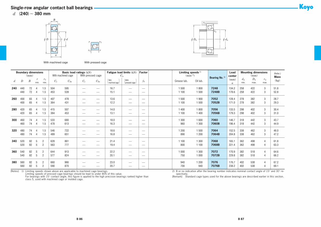
With machined cage With pressed cage
r1 r
r r1
ra
u Da u da
ra
a
r
r
u D u d
r1
r
B
Single-row angular contact ball bearings
240 440 72 4 1.5 504 595 ⎯ ⎯ 16.7 ⎯ ⎯ 1 500 1 800 7248 134.2 258 422 3 51.8240 440 72 4 1.5 453 539 ⎯ ⎯ 15.1 ⎯ ⎯ 1 100 1 500 7248B 178.6 258 422 3 52.8
260 400 65 4 1.5 407 478 ⎯ ⎯ 13.6 ⎯ ⎯ 1 500 1 900 7052 128.4 278 382 3 28.7260 400 65 4 1.5 364 431 ⎯ ⎯ 12.2 ⎯ ⎯ 1 100 1 500 7052B 171.0 278 382 3 29.3
280 420 65 4 1.5 415 507 ⎯ ⎯ 14.0 ⎯ ⎯ 1 400 1 800 7056 133.5 298 402 3 30.4280 420 65 4 1.5 384 453 ⎯ ⎯ 13.1 ⎯ ⎯ 1 100 1 400 7056B 179.3 298 402 3 31.0
300 460 74 4 1.5 533 680 ⎯ ⎯ 18.0 ⎯ ⎯ 1 300 1 600 7060 146.7 318 442 3 43.7300 460 74 4 1.5 478 613 ⎯ ⎯ 16.3 ⎯ ⎯ 960 1 300 7060B 196.4 318 442 3 44.9
320 480 74 4 1.5 546 722 ⎯ ⎯ 18.6 ⎯ ⎯ 1 200 1 500 7064 152.5 338 462 3 46.0320 480 74 4 1.5 489 651 ⎯ ⎯ 16.8 ⎯ ⎯ 890 1 200 7064B 204.8 338 462 3 47.2
340 520 82 5 2 628 861 ⎯ ⎯ 21.4 ⎯ ⎯ 1 100 1 300 7068 165.1 362 498 4 61.8340 520 82 5 2 563 777 ⎯ ⎯ 19.4 ⎯ ⎯ 800 1 100 7068B 221.4 362 498 4 63.3
360 540 82 5 2 644 913 ⎯ ⎯ 22.2 ⎯ ⎯ 1 000 1 300 7072 170.9 382 518 4 64.6360 540 82 5 2 577 824 ⎯ ⎯ 20.1 ⎯ ⎯ 750 1 000 7072B 229.8 382 518 4 66.2
380 560 82 5 2 660 966 ⎯ ⎯ 23.0 ⎯ ⎯ 940 1 200 7076 176.7 402 538 4 67.2380 560 82 5 2 590 870 ⎯ ⎯ 20.7 ⎯ ⎯ 700 940 7076B 238.2 402 538 4 69.1
Boundary dimensions Basic load ratings (kN) Fatigue load limits (kN) Factor Limiting speeds 1)
Bearing No. 2)
Loadcenter(mm)
a
Mounting dimensions (Refer.)
Mass(kg)
(mm) With machined cage With pressed cage Cu (min−1) (mm)
d D Br r1 Cr C0r Cr C0r f 0 Grease lub. Oil lub.
da Da ra
min. min. min. max. max.
[Notes] 1) Limiting speeds shown above are applicable to machined cage bearings.Limiting speeds of pressed cage bearings should be kept to under 80% of this value.For bearings with 15° contact angle, this figure is applied to the high precision bearings ranked higher thanclass 5, used with machined cage or molded cage.
2) B, C or no indication after the bearing number indicates nominal contact angle of 40°, 15° and30° respectively.
[Remark] Standard cage types used for the above bearings are described earlier in this section.
With �machined cage
With �pressed cage
B 86 B 87
d (240) ∼ 380 mm
2) B or no indication after the bearing number indicates nominal contact angle of 15° and 30° re-spectively.
[Remark] Standard cage types used for the above bearings are described earlier in this section.
[Notes] 1) Limiting speeds shown above are applicable to machined cage bearings.Limiting speeds of pressed cage bearings should be kept to under 80% of this value.For bearings with 15° contact angle, this figure is applied to the high precision bearings ranked higher thanclass 5, used with machined cage or molded cage.

Back-to-backDB
Face-to-faceDF
(With machined cages) (With pressed cages)
TandemDT
Back-to-backDB
Face-to-faceDF
TandemDT
r
u D
rr
u D u d
rrB1
a2
rr
u D u d
r1r1
B1
a1
r
u d
rB1
r1 rr
u D u d
r1r1
B1
a2
rr
u D
r1r1
B1
a1u d
r
r
u D u d
r1
r1
B1
(With machined cages) (With pressed cages)
u Da u da
ra
u Da
ra
u Db u da
ra
u Db u da
rb rbra
u db
rb
ra
Angular contact ball bearings (matched pair)
Boundary dimensions Basic load ratings
(kN)
Fatigue load limits
(kN)
Factor
Limiting speeds
1)
Bearing No.
2)
Load centerspread
(mm)
Mounting dimensions
(Refer.)
Mass
(kg)
(mm)
With machined cages With pressed cages
C
u
(min
−
1
) (mm)
d D B
1
r r
1
C
r
C
0r
C
r
C
0r
f
0
Greaselub.
Oil lub.Back-to-back
DBFace-to-face
DFTandem
DT
a
1
a
2
d
a
d
b
D
a
D
b
r
a
r
b
min. min. min. min. max. max. max. max.
10
22 12 0.3 0.15 6.10 3.05
⎯ ⎯
0.120
⎯
14.2 42 000 55 000
7900CDB 7900CDF 7900CDT
10.3 1.7 12.5
⎯
19.5 20.8 0.3 0.15 0.016
10
26 16 0.3 0.15 10.1 4.65
⎯ ⎯
0.240
⎯ ⎯
27 000 34 000
7000DB 7000DF 7000DT
18.2 2.2 12.5
⎯
23.5 24.8 0.3 0.15 0.042
10
26 16 0.3 0.15 9.40 4.35
⎯ ⎯
0.220
⎯ ⎯
20 000 27 000
7000BDB 7000BDF 7000BDT
23.1 7.1 12.5
⎯
23.5 24.8 0.3 0.15 0.042
10
26 16 0.3 0.15 10.7 4.95
⎯ ⎯
0.250
⎯
12.5 37 000 50 000
7000CDB 7000CDF 7000CDT
12.7 3.3 12.5
⎯
23.5 24.8 0.3 0.15 0.042
10
30 18 0.6 0.3 9.50 4.40 11.0 5.45 0.230 0.280
⎯
23 000 29 000
7200DB 7200DF 7200DT
20.8 2.8 14.5 12.5 25.5 27.5 0.6 0.3 0.062
10
30 18 0.6 0.3 8.70 4.05 10.1 5.05 0.210 0.260
⎯
18 000 23 000
7200BDB 7200BDF 7200BDT
26.2 8.2 14.5 12.5 25.5 27.5 0.6 0.3 0.062
10
30 18 0.6 0.3 10.2 4.70 11.8 5.85 0.240 0.300 13.4 32 000 43 000
7200CDB 7200CDF 7200CDT
14.5 3.5 14.5 12.5 25.5 27.5 0.6 0.3 0.062
10
35 22 0.6 0.3 17.3 7.55 18.9 8.60 0.590 0.680
⎯
21 000 27 000
7300DB 7300DF 7300DT
24.0 2.0 14.5 12.5 30.5 32.5 0.6 0.3 0.108
12
24 12 0.3 0.15 6.45 3.45
⎯ ⎯
0.140
⎯
14.7 37 000 49 000
7901CDB 7901CDF 7901CDT
10.8 1.2 14.5
⎯
21.5 22.8 0.3 0.15 0.020
12
28 16 0.3 0.15 11.0 5.45
⎯ ⎯
0.280
⎯ ⎯
23 000 29 000
7001DB 7001DF 7001DT
19.9 3.9 14.5
⎯
25.5 26.8 0.3 0.15 0.048
12
28 16 0.3 0.15 10.1 5.05
⎯ ⎯
0.260
⎯ ⎯
18 000 23 000
7001BDB 7001BDF 7001BDT
25.2 9.2 14.5
⎯
25.5 26.8 0.3 0.15 0.048
12
28 16 0.3 0.15 11.8 5.85
⎯ ⎯
0.300
⎯
13.4 32 000 43 000
7001CDB 7001CDF 7001CDT
13.5 2.5 14.5
⎯
25.5 26.8 0.3 0.15 0.048
12
32 20 0.6 0.3 15.1 7.25 16.2 8.05 0.560 0.620
⎯
22 000 27 000
7201DB 7201DF 7201DT
22.7 2.7 16.5 14.5 27.5 29.5 0.6 0.3 0.076
12
32 20 0.6 0.3 14.0 6.80 15.1 7.50 0.480 0.530
⎯
16 000 22 000
7201BDB 7201BDF 7201BDT
28.5 8.5 16.5 14.5 27.5 29.5 0.6 0.3 0.076
12
32 20 0.6 0.3 16.0 7.70 17.2 8.55 0.600 0.670 12.5 30 000 40 000
7201CDB 7201CDF 7201CDT
15.9 4.1 16.5 14.5 27.5 29.5 0.6 0.3 0.076
12
37 24 1 0.6 20.7 9.20 22.7 10.5 0.720 0.820
⎯
20 000 24 000
7301DB 7301DF 7301DT
26.2 2.2 17.5 16.5 31.5 32.5 1 0.6 0.130
15
28 14 0.3 0.15 9.65 5.30
⎯ ⎯
0.210
⎯
14.5 31 000 41 000
7902CDB 7902CDF 7902CDT
12.8 1.2 17.5
⎯
25.5 26.8 0.3 0.15 0.030
15
32 18 0.3 0.15 12.4 6.85
⎯ ⎯
0.350
⎯ ⎯
20 000 26 000
7002DB 7002DF 7002DT
22.6 4.6 17.5
⎯
29.5 30.8 0.3 0.15 0.070
15
32 18 0.3 0.15 11.3 6.30
⎯ ⎯
0.320
⎯ ⎯
15 000 20 000
7002BDB 7002BDF 7002BDT
29.1 11.1 17.5
⎯
29.5 30.8 0.3 0.15 0.070
15
32 18 0.3 0.15 13.4 7.40
⎯ ⎯
0.380
⎯
14.1 28 000 37 000
7002CDB 7002CDF 7002CDT
15.3 2.7 17.5
⎯
29.5 30.8 0.3 0.15 0.070
15
35 22 0.6 0.3 16.4 8.55 16.4 8.55 0.600 0.600
⎯
19 000 24 000
7202DB 7202DF 7202DT
25.7 3.7 19.5 17.5 30.5 32.5 0.6 0.3 0.096
15
35 22 0.6 0.3 15.1 7.85 15.1 7.85 0.520 0.520
⎯
14 000 19 000
7202BDB 7202BDF 7202BDT
32.4 10.4 19.5 17.5 30.5 32.5 0.6 0.3 0.096
15
35 22 0.6 0.3 17.6 9.15 17.6 9.15 0.680 0.680 13.3 26 000 35 000
7202CDB 7202CDF 7202CDT
17.8 4.2 19.5 17.5 30.5 32.5 0.6 0.3 0.096
15
42 26 1 0.6 25.4 12.9 27.3 14.4 0.990 1.10
⎯
16 000 20 000
7302DB 7302DF 7302DT
30.0 4.0 20.5 19.5 36.5 37.5 1 0.6 0.176
17
30 14 0.3 0.15 10.1 5.90
⎯ ⎯
0.240
⎯
14.9 28 000 38 000
7903CDB 7903CDF 7903CDT
13.4 0.6 19.5
⎯
27.5 28.8 0.3 0.15 0.032
17
35 20 0.3 0.15 13.7 8.25
⎯ ⎯
0.430
⎯ ⎯
18 000 23 000
7003DB 7003DF 7003DT
25.3 5.3 19.5
⎯
32.5 33.8 0.3 0.15 0.090
17
35 20 0.3 0.15 12.4 7.50
⎯ ⎯
0.390
⎯ ⎯
14 000 18 000
7003BDB 7003BDF 7003BDT
32.2 12.2 19.5
⎯
32.5 33.8 0.3 0.15 0.090
[Notes] 1) Limiting speeds shown above are applicable to machined cage bearings.Limiting speeds of pressed cage bearings should be kept to under 80% of this value.For bearings with 15
°
contact angle, this figure is applied to the high precision bearings ranked higher thanclass 5, used with machined cages or molded cages.
2) B, C or no indication after the bearing number indicates nominal contact angle of 40
°
, 15
°
and 30
°
respectively.[Remark] Standard cage types used for the above bearings are described earlier in this section.
With �machined cages
With �pressed cages
B 88 B 89
d
10
∼
(
17
)
mm
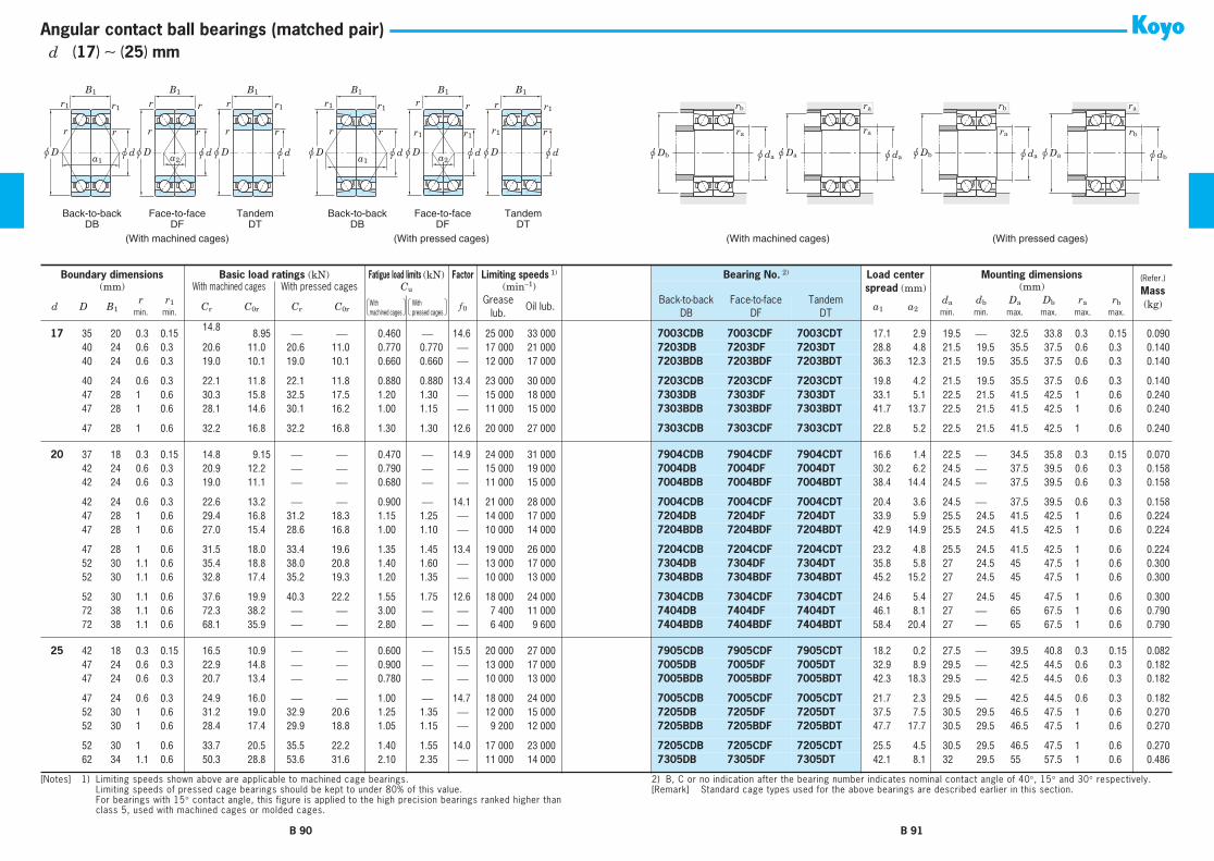
Back-to-backDB
Face-to-faceDF
(With machined cages) (With pressed cages)
TandemDT
Back-to-backDB
Face-to-faceDF
TandemDT
r
u D
rr
u D u d
rrB1
a2
rr
u D u d
r1r1
B1
a1
r
u d
rB1
r1 rr
u D u d
r1r1
B1
a2
rr
u D
r1r1
B1
a1u d
r
r
u D u d
r1
r1
B1
(With machined cages) (With pressed cages)
u Da u da
ra
u Da
ra
u Db u da
ra
u Db u da
rb rbra
u db
rb
ra
Angular contact ball bearings (matched pair)
17
35 20 0.3 0.1514.8
8.95
⎯ ⎯
0.460
⎯
14.6 25 000 33 000
7003CDB 7003CDF 7003CDT
17.1 2.9 19.5
⎯
32.5 33.8 0.3 0.15 0.090
17
40 24 0.6 0.3 20.6 11.0 20.6 11.0 0.770 0.770
⎯
17 000 21 000
7203DB 7203DF 7203DT
28.8 4.8 21.5 19.5 35.5 37.5 0.6 0.3 0.140
17
40 24 0.6 0.3 19.0 10.1 19.0 10.1 0.660 0.660
⎯
12 000 17 000
7203BDB 7203BDF 7203BDT
36.3 12.3 21.5 19.5 35.5 37.5 0.6 0.3 0.140
17
40 24 0.6 0.3 22.1 11.8 22.1 11.8 0.880 0.880 13.4 23 000 30 000
7203CDB 7203CDF 7203CDT
19.8 4.2 21.5 19.5 35.5 37.5 0.6 0.3 0.140
17
47 28 1 0.6 30.3 15.8 32.5 17.5 1.20 1.30
⎯
15 000 18 000
7303DB 7303DF 7303DT
33.1 5.1 22.5 21.5 41.5 42.5 1 0.6 0.240
17
47 28 1 0.6 28.1 14.6 30.1 16.2 1.00 1.15
⎯
11 000 15 000
7303BDB 7303BDF 7303BDT
41.7 13.7 22.5 21.5 41.5 42.5 1 0.6 0.240
17
47 28 1 0.6 32.2 16.8 32.2 16.8 1.30 1.30 12.6 20 000 27 000
7303CDB 7303CDF 7303CDT
22.8 5.2 22.5 21.5 41.5 42.5 1 0.6 0.240
20
37 18 0.3 0.15 14.8 9.15
⎯ ⎯
0.470
⎯
14.9 24 000 31 000
7904CDB 7904CDF 7904CDT
16.6 1.4 22.5
⎯
34.5 35.8 0.3 0.15 0.070
20
42 24 0.6 0.3 20.9 12.2
⎯ ⎯
0.790
⎯ ⎯
15 000 19 000
7004DB 7004DF 7004DT
30.2 6.2 24.5
⎯
37.5 39.5 0.6 0.3 0.158
20
42 24 0.6 0.3 19.0 11.1
⎯ ⎯
0.680
⎯ ⎯
11 000 15 000
7004BDB 7004BDF 7004BDT
38.4 14.4 24.5
⎯
37.5 39.5 0.6 0.3 0.158
20
42 24 0.6 0.3 22.6 13.2
⎯ ⎯
0.900
⎯
14.1 21 000 28 000
7004CDB 7004CDF 7004CDT
20.4 3.6 24.5
⎯
37.5 39.5 0.6 0.3 0.158
20
47 28 1 0.6 29.4 16.8 31.2 18.3 1.15 1.25
⎯
14 000 17 000
7204DB 7204DF 7204DT
33.9 5.9 25.5 24.5 41.5 42.5 1 0.6 0.224
20
47 28 1 0.6 27.0 15.4 28.6 16.8 1.00 1.10
⎯
10 000 14 000
7204BDB 7204BDF 7204BDT
42.9 14.9 25.5 24.5 41.5 42.5 1 0.6 0.224
20
47 28 1 0.6 31.5 18.0 33.4 19.6 1.35 1.45 13.4 19 000 26 000
7204CDB 7204CDF 7204CDT
23.2 4.8 25.5 24.5 41.5 42.5 1 0.6 0.224
20
52 30 1.1 0.6 35.4 18.8 38.0 20.8 1.40 1.60
⎯
13 000 17 000
7304DB 7304DF 7304DT
35.8 5.8 27 24.5 45 47.5 1 0.6 0.300
20
52 30 1.1 0.6 32.8 17.4 35.2 19.3 1.20 1.35
⎯
10 000 13 000
7304BDB 7304BDF 7304BDT
45.2 15.2 27 24.5 45 47.5 1 0.6 0.300
20
52 30 1.1 0.6 37.6 19.9 40.3 22.2 1.55 1.75 12.6 18 000 24 000
7304CDB 7304CDF 7304CDT
24.6 5.4 27 24.5 45 47.5 1 0.6 0.300
20
72 38 1.1 0.6 72.3 38.2
⎯ ⎯
3.00
⎯ ⎯
7 400 11 000
7404DB 7404DF 7404DT
46.1 8.1 27
⎯
65 67.5 1 0.6 0.790
20
72 38 1.1 0.6 68.1 35.9 ⎯ ⎯ 2.80 ⎯ ⎯ 6 400 9 600 7404BDB 7404BDF 7404BDT 58.4 20.4 27 ⎯ 65 67.5 1 0.6 0.790
25 42 18 0.3 0.15 16.5 10.9 ⎯ ⎯ 0.600 ⎯ 15.5 20 000 27 000 7905CDB 7905CDF 7905CDT 18.2 0.2 27.5 ⎯ 39.5 40.8 0.3 0.15 0.08225 47 24 0.6 0.3 22.9 14.8 ⎯ ⎯ 0.900 ⎯ ⎯ 13 000 17 000 7005DB 7005DF 7005DT 32.9 8.9 29.5 ⎯ 42.5 44.5 0.6 0.3 0.18225 47 24 0.6 0.3 20.7 13.4 ⎯ ⎯ 0.780 ⎯ ⎯ 10 000 13 000 7005BDB 7005BDF 7005BDT 42.3 18.3 29.5 ⎯ 42.5 44.5 0.6 0.3 0.182
25 47 24 0.6 0.3 24.9 16.0 ⎯ ⎯ 1.00 ⎯ 14.7 18 000 24 000 7005CDB 7005CDF 7005CDT 21.7 2.3 29.5 ⎯ 42.5 44.5 0.6 0.3 0.18225 52 30 1 0.6 31.2 19.0 32.9 20.6 1.25 1.35 ⎯ 12 000 15 000 7205DB 7205DF 7205DT 37.5 7.5 30.5 29.5 46.5 47.5 1 0.6 0.27025 52 30 1 0.6 28.4 17.4 29.9 18.8 1.05 1.15 ⎯ 9 200 12 000 7205BDB 7205BDF 7205BDT 47.7 17.7 30.5 29.5 46.5 47.5 1 0.6 0.270
25 52 30 1 0.6 33.7 20.5 35.5 22.2 1.40 1.55 14.0 17 000 23 000 7205CDB 7205CDF 7205CDT 25.5 4.5 30.5 29.5 46.5 47.5 1 0.6 0.27025 62 34 1.1 0.6 50.3 28.8 53.6 31.6 2.10 2.35 ⎯ 11 000 14 000 7305DB 7305DF 7305DT 42.1 8.1 32 29.5 55 57.5 1 0.6 0.486
Boundary dimensions Basic load ratings (kN) Fatigue load limits (kN) Factor Limiting speeds 1) Bearing No. 2) Load centerspread (mm)
Mounting dimensions (Refer.)
Mass(kg)
(mm) With machined cages With pressed cages Cu (min−1) (mm)
d D B1r r1 Cr C0r Cr C0r f 0
Greaselub.
Oil lub.Back-to-back
DBFace-to-face
DFTandem
DTa1 a2
da db Da Db ra rbmin. min. min. min. max. max. max. max.
[Notes] 1) Limiting speeds shown above are applicable to machined cage bearings.Limiting speeds of pressed cage bearings should be kept to under 80% of this value.For bearings with 15° contact angle, this figure is applied to the high precision bearings ranked higher thanclass 5, used with machined cages or molded cages.
2) B, C or no indication after the bearing number indicates nominal contact angle of 40°, 15° and 30° respectively.[Remark] Standard cage types used for the above bearings are described earlier in this section.
With �machined cages
With �pressed cages
B 90 B 91
d (17) ∼ (25) mm

Back-to-backDB
Face-to-faceDF
(With machined cages) (With pressed cages)
TandemDT
Back-to-backDB
Face-to-faceDF
TandemDT
r
u D
rr
u D u d
rrB1
a2
rr
u D u d
r1r1
B1
a1
r
u d
rB1
r1 rr
u D u d
r1r1
B1
a2
rr
u D
r1r1
B1
a1u d
r
r
u D u d
r1
r1
B1
(With machined cages) (With pressed cages)
u Da u da
ra
u Da
ra
u Db u da
ra
u Db u da
rb rbra
u db
rb
ra
Angular contact ball bearings (matched pair)
25 62 34 1.1 0.6 46.5 26.6 49.5 29.2 1.85 2.00 ⎯ 8 300 11 000 7305BDB 7305BDF 7305BDT 53.5 19.5 32 29.5 55 57.5 1 0.6 0.48625 62 34 1.1 0.6 53.5 30.6 57.0 33.7 2.40 2.65 12.8 15 000 20 000 7305CDB 7305CDF 7305CDT 28.7 5.3 32 29.5 55 57.5 1 0.6 0.48625 80 42 1.5 1 80.7 46.3 86.6 51.5 3.60 4.00 ⎯ 6 400 9 100 7405DB 7405DF 7405DT 52.8 10.8 33.5 30.5 71.5 74.5 1.5 1 1.05
25 80 42 1.5 1 74.9 43.0 80.4 47.8 3.10 3.40 ⎯ 5 500 8 200 7405BDB 7405BDF 7405BDT 67.2 25.2 33.5 30.5 71.5 74.5 1.5 1 1.05
30 47 18 0.3 0.15 16.8 12.5 ⎯ ⎯ 0.650 ⎯ 15.9 18 000 23 000 7906CDB 7906CDF 7906CDT 19.3 1.3 32.5 ⎯ 44.5 45.8 0.3 0.15 0.09230 55 26 1 0.6 29.5 20.2 ⎯ ⎯ 1.20 ⎯ ⎯ 11 000 14 000 7006DB 7006DF 7006DT 37.5 11.5 35.5 ⎯ 49.5 50.5 1 0.6 0.26630 55 26 1 0.6 26.7 18.4 ⎯ ⎯ 1.05 ⎯ ⎯ 8 500 11 000 7006BDB 7006BDF 7006BDT 48.7 22.7 35.5 ⎯ 49.5 50.5 1 0.6 0.266
30 55 26 1 0.6 32.2 22.0 ⎯ ⎯ 1.40 ⎯ 14.9 16 000 21 000 7006CDB 7006CDF 7006CDT 24.4 1.6 35.5 ⎯ 49.5 50.5 1 0.6 0.26630 62 32 1 0.6 43.3 27.4 45.7 29.7 1.80 1.95 ⎯ 10 000 13 000 7206DB 7206DF 7206DT 43.0 11.0 35.5 34.5 56.5 57.5 1 0.6 0.41630 62 32 1 0.6 39.5 25.0 41.6 27.1 1.55 1.65 ⎯ 7 700 10 000 7206BDB 7206BDF 7206BDT 55.2 23.2 35.5 34.5 56.5 57.5 1 0.6 0.416
30 62 32 1 0.6 46.8 29.5 49.4 32.0 2.05 2.20 14.0 14 000 19 000 7206CDB 7206CDF 7206CDT 28.5 3.5 35.5 34.5 56.5 57.5 1 0.6 0.41630 72 38 1.1 0.6 61.1 37.8 64.8 41.2 2.60 2.85 ⎯ 9 200 12 000 7306DB 7306DF 7306DT 49.0 11.0 37 34.5 65 67.5 1 0.6 0.72430 72 38 1.1 0.6 56.1 34.7 59.4 37.9 2.25 2.45 ⎯ 6 900 9 200 7306BDB 7306BDF 7306BDT 62.6 24.6 37 34.5 65 67.5 1 0.6 0.724
30 72 38 1.1 0.6 65.6 40.5 69.5 44.2 3.00 3.25 13.4 13 000 17 000 7306CDB 7306CDF 7306CDT 32.9 5.1 37 34.5 65 67.5 1 0.6 0.72430 90 46 1.5 1 96.7 56.9 104 63.2 4.35 4.85 ⎯ 5 700 8 100 7406DB 7406DF 7406DT 58.5 12.5 38.5 35.5 81.5 84.5 1.5 1 1.3730 90 46 1.5 1 89.7 52.8 96.3 58.6 3.75 4.15 ⎯ 4 900 7 300 7406BDB 7406BDF 7406BDT 74.6 28.6 38.5 35.5 81.5 84.5 1.5 1 1.37
35 55 20 0.6 0.3 25.5 19.4 ⎯ ⎯ 1.10 ⎯ 15.7 15 000 20 000 7907CDB 7907CDF 7907CDT 22.1 2.1 39.5 ⎯ 50.5 52.5 0.6 0.3 0.14835 62 28 1 0.6 35.5 25.2 ⎯ ⎯ 1.50 ⎯ ⎯ 9 800 12 000 7007DB 7007DF 7007DT 42.3 14.3 40.5 ⎯ 56.5 57.5 1 0.6 0.34035 62 28 1 0.6 32.0 22.8 ⎯ ⎯ 1.30 ⎯ ⎯ 7 300 9 800 7007BDB 7007BDF 7007BDT 55.1 27.1 40.5 ⎯ 56.5 57.5 1 0.6 0.340
35 62 28 1 0.6 38.8 27.4 ⎯ ⎯ 1.70 ⎯ 15.0 13 000 18 000 7007CDB 7007CDF 7007CDT 27.0 1.0 40.5 ⎯ 56.5 57.5 1 0.6 0.34035 72 34 1.1 0.6 57.1 37.3 60.3 40.4 2.45 2.65 ⎯ 8 800 11 000 7207DB 7207DF 7207DT 48.5 14.5 42 39.5 65 67.5 1 0.6 0.59035 72 34 1.1 0.6 52.1 34.1 54.9 36.9 2.10 2.25 ⎯ 6 600 8 800 7207BDB 7207BDF 7207BDT 62.7 28.7 42 39.5 65 67.5 1 0.6 0.590
35 72 34 1.1 0.6 61.7 40.2 65.1 43.5 2.75 3.00 14.0 12 000 16 000 7207CDB 7207CDF 7207CDT 31.6 2.4 42 39.5 65 67.5 1 0.6 0.59035 80 42 1.5 1 71.8 44.0 81.1 52.8 3.05 3.65 ⎯ 8 200 10 000 7307DB 7307DF 7307DT 54.8 12.8 43.5 40.5 71.5 74.5 1.5 1 0.95035 80 42 1.5 1 65.9 40.5 74.4 48.6 2.65 3.15 ⎯ 6 200 8 200 7307BDB 7307BDF 7307BDT 70.1 28.1 43.5 40.5 71.5 74.5 1.5 1 0.950
35 80 42 1.5 1 77.0 47.2 86.9 56.6 3.50 4.20 13.4 11 000 15 000 7307CDB 7307CDF 7307CDT 36.7 5.3 43.5 40.5 71.5 74.5 1.5 1 0.95035 100 50 1.5 1 123 73.9 132 82.1 5.70 6.35 ⎯ 5 000 7 200 7407DB 7407DF 7407DT 65.2 15.2 43.5 40.5 91.5 94.5 1.5 1 1.90
Boundary dimensions Basic load ratings (kN) Fatigue load limits (kN) Factor Limiting speeds 1) Bearing No. 2) Load centerspread (mm)
Mounting dimensions (Refer.)
Mass(kg)
(mm) With machined cages With pressed cages Cu (min−1) (mm)
d D B1r r1 Cr C0r Cr C0r f 0
Greaselub.
Oil lub.Back-to-back
DBFace-to-face
DFTandem
DTa1 a2
da db Da Db ra rbmin. min. min. min. max. max. max. max.
[Notes] 1) Limiting speeds shown above are applicable to machined cage bearings.Limiting speeds of pressed cage bearings should be kept to under 80% of this value.For bearings with 15° contact angle, this figure is applied to the high precision bearings ranked higher thanclass 5, used with machined cages or molded cages.
2) B, C or no indication after the bearing number indicates nominal contact angle of 40°, 15° and 30° respectively.[Remark] Standard cage types used for the above bearings are described earlier in this section.
With �machined cages
With �pressed cages
B 92 B 93
d (25) ∼ (35) mm

Back-to-backDB
Face-to-faceDF
(With machined cages) (With pressed cages)
TandemDT
Back-to-backDB
Face-to-faceDF
TandemDT
r
u D
rr
u D u d
rrB1
a2
rr
u D u d
r1r1
B1
a1
r
u d
rB1
r1 rr
u D u d
r1r1
B1
a2
rr
u D
r1r1
B1
a1u d
r
r
u D u d
r1
r1
B1
(With machined cages) (With pressed cages)
u Da u da
ra
u Da
ra
u Db u da
ra
u Db u da
rb rbra
u db
rb
ra
Angular contact ball bearings (matched pair)
35 100 50 1.5 1 114 68.6 122 76.2 4.90 5.45 ⎯ 4 300 6 500 7407BDB 7407BDF 7407BDT 83.3 33.3 43.5 40.5 91.5 94.5 1.5 1 1.90
40 62 24 0.6 0.3 32.0 24.9 ⎯ ⎯ 1.40 ⎯ 15.7 13 000 18 000 7908CDB 7908CDF 7908CDT 25.7 1.7 44.5 ⎯ 57.5 59.5 0.6 0.3 0.21440 68 30 1 0.6 38.1 29.2 ⎯ ⎯ 1.65 ⎯ ⎯ 8 900 11 000 7008DB 7008DF 7008DT 46.3 16.3 45.5 ⎯ 62.5 63.5 1 0.6 0.42040 68 30 1 0.6 34.2 26.4 ⎯ ⎯ 1.45 ⎯ ⎯ 6 600 8 900 7008BDB 7008BDF 7008BDT 60.5 30.5 45.5 ⎯ 62.5 63.5 1 0.6 0.420
40 68 30 1 0.6 41.7 31.8 ⎯ ⎯ 1.90 ⎯ 15.4 12 000 16 000 7008CDB 7008CDF 7008CDT 29.5 0.5 45.5 ⎯ 62.5 63.5 1 0.6 0.42040 80 36 1.1 0.6 68.2 46.7 71.7 50.3 3.00 3.25 ⎯ 8 000 10 000 7208DB 7208DF 7208DT 52.7 16.7 47 44.5 73 75.5 1 0.6 0.76440 80 36 1.1 0.6 62.1 42.7 65.2 45.9 2.60 2.80 ⎯ 6 000 8 000 7208BDB 7208BDF 7208BDT 68.3 32.3 47 44.5 73 75.5 1 0.6 0.764
40 80 36 1.1 0.6 73.8 50.4 77.6 54.3 3.45 3.70 14.2 11 000 15 000 7208CDB 7208CDF 7208CDT 34.1 1.9 47 44.5 73 75.5 1 0.6 0.76440 90 46 1.5 1 87.8 54.9 99.1 65.9 3.85 4.60 ⎯ 7 400 9 200 7308DB 7308DF 7308DT 60.5 14.5 48.5 45.5 81.5 84.5 1.5 1 1.3140 90 46 1.5 1 80.6 50.5 91.0 60.6 3.30 3.95 ⎯ 5 500 7 400 7308BDB 7308BDF 7308BDT 77.5 31.5 48.5 45.5 81.5 84.5 1.5 1 1.31
40 90 46 1.5 1 94.1 58.8 106 70.5 4.40 5.25 13.4 10 000 14 000 7308CDB 7308CDF 7308CDT 40.4 5.6 48.5 45.5 81.5 84.5 1.5 1 1.3140 110 54 2 1 142 87.1 152 96.8 6.70 7.45 ⎯ 4 600 6 600 7408DB 7408DF 7408DT 70.9 16.9 50 45.5 100 104.5 2 1 2.4640 110 54 2 1 132 80.8 141 89.8 5.75 6.40 ⎯ 3 900 5 900 7408BDB 7408BDF 7408BDT 90.8 36.8 50 45.5 100 104.5 2 1 2.46
45 68 24 0.6 0.3 33.7 28.2 ⎯ ⎯ 1.55 ⎯ 16.0 12 000 16 000 7909CDB 7909CDF 7909CDT 27.1 3.1 49.5 ⎯ 63.5 65.5 0.6 0.3 0.25445 75 32 1 0.6 45.2 35.4 ⎯ ⎯ 2.00 ⎯ ⎯ 8 000 10 000 7009DB 7009DF 7009DT 50.7 18.7 50.5 ⎯ 69.5 70.5 1 0.6 0.52045 75 32 1 0.6 40.6 32.0 ⎯ ⎯ 1.75 ⎯ ⎯ 6 000 8 000 7009BDB 7009BDF 7009BDT 66.3 34.3 50.5 ⎯ 69.5 70.5 1 0.6 0.520
45 75 32 1 0.6 49.6 38.5 ⎯ ⎯ 2.25 ⎯ 15.4 11 000 15 000 7009CDB 7009CDF 7009CDT 32.1 0.1 50.5 ⎯ 69.5 70.5 1 0.6 0.52045 85 38 1.1 0.6 76.6 53.2 80.5 57.2 3.40 3.70 ⎯ 7 500 9 400 7209DB 7209DF 7209DT 56.0 18.0 52 49.5 78 80.5 1 0.6 0.86045 85 38 1.1 0.6 69.7 48.6 73.2 52.3 2.95 3.20 ⎯ 5 600 7 500 7209BDB 7209BDF 7209BDT 72.8 34.8 52 49.5 78 80.5 1 0.6 0.860
45 85 38 1.1 0.6 82.9 57.4 87.1 61.8 3.90 4.20 14.2 10 000 14 000 7209CDB 7209CDF 7209CDT 36.2 1.8 52 49.5 78 80.5 1 0.6 0.86045 100 50 1.5 1 112 74.2 119 80.9 5.15 5.60 ⎯ 6 600 8 200 7309DB 7309DF 7309DT 67.2 17.2 53.5 50.5 91.5 94.5 1.5 1 1.7545 100 50 1.5 1 103 68.2 109 74.3 4.40 4.85 ⎯ 4 900 6 600 7309BDB 7309BDF 7309BDT 86.3 36.3 53.5 50.5 91.5 94.5 1.5 1 1.75
45 100 50 1.5 1 120 79.5 127 86.7 5.85 6.40 13.5 9 000 12 000 7309CDB 7309CDF 7309CDT 44.6 5.4 53.5 50.5 91.5 94.5 1.5 1 1.7545 120 58 2 1 173 108 185 120 8.35 9.30 ⎯ 4 200 6 000 7409DB 7409DF 7409DT 77.2 19.2 55 50.5 110 114.5 2 1 3.1045 120 58 2 1 160 100 172 111 7.20 8.00 ⎯ 3 600 5 400 7409BDB 7409BDF 7409BDT 99.1 41.1 55 50.5 110 114.5 2 1 3.10
50 72 24 0.6 0.3 35.4 31.4 ⎯ ⎯ 1.70 ⎯ 16.2 11 000 15 000 7910CDB 7910CDF 7910CDT 28.3 4.3 54.5 ⎯ 67.5 69.5 0.6 0.3 0.25650 80 32 1 0.6 48.0 40.2 ⎯ ⎯ 2.20 ⎯ ⎯ 7 300 9 200 7010DB 7010DF 7010DT 53.8 21.8 55.5 ⎯ 74.5 75.5 1 0.6 0.580
Boundary dimensions Basic load ratings (kN) Fatigue load limits (kN) Factor Limiting speeds 1) Bearing No. 2) Load centerspread (mm)
Mounting dimensions (Refer.)
Mass(kg)
(mm) With machined cages With pressed cages Cu (min−1) (mm)
d D B1r r1 Cr C0r Cr C0r f 0
Greaselub.
Oil lub.Back-to-back
DBFace-to-face
DFTandem
DTa1 a2
da db Da Db ra rbmin. min. min. min. max. max. max. max.
[Notes] 1) Limiting speeds shown above are applicable to machined cage bearings.Limiting speeds of pressed cage bearings should be kept to under 80% of this value.For bearings with 15° contact angle, this figure is applied to the high precision bearings ranked higher thanclass 5, used with machined cages or molded cages.
2) B, C or no indication after the bearing number indicates nominal contact angle of 40°, 15° and 30° respectively.[Remark] Standard cage types used for the above bearings are described earlier in this section.
With �machined cages
With �pressed cages
B 94 B 95
d (35) ∼ (50) mm

Back-to-backDB
Face-to-faceDF
(With machined cages) (With pressed cages)
TandemDT
Back-to-backDB
Face-to-faceDF
TandemDT
r
u D
rr
u D u d
rrB1
a2
rr
u D u d
r1r1
B1
a1
r
u d
rB1
r1 rr
u D u d
r1r1
B1
a2
rr
u D
r1r1
B1
a1u d
r
r
u D u d
r1
r1
B1
(With machined cages) (With pressed cages)
u Da u da
ra
u Da
ra
u Db u da
ra
u Db u da
rb rbra
u db
rb
ra
Angular contact ball bearings (matched pair)
50 80 32 1 0.6 43.1 36.2 ⎯ ⎯ 1.90 ⎯ ⎯ 5 500 7 400 7010BDB 7010BDF 7010BDT 70.5 38.5 55.5 ⎯ 74.5 75.5 1 0.6 0.58050 80 32 1 0.6 52.7 43.9 ⎯ ⎯ 2.50 ⎯ 15.7 10 000 13 000 7010CDB 7010CDF 7010CDT 33.6 1.6 55.5 ⎯ 74.5 75.5 1 0.6 0.58050 90 40 1.1 0.6 80.0 58.7 83.8 62.9 3.60 3.85 ⎯ 6 800 8 500 7210DB 7210DF 7210DT 60.7 20.7 57 54.5 83 85.5 1 0.6 0.970
50 90 40 1.1 0.6 72.5 53.5 75.9 57.3 3.15 3.35 ⎯ 5 100 6 800 7210BDB 7210BDF 7210BDT 79.2 39.2 57 54.5 83 85.5 1 0.6 0.97050 90 40 1.1 0.6 86.9 63.6 91.0 68.1 4.10 4.40 14.6 9 400 12 000 7210CDB 7210CDF 7210CDT 38.9 1.1 57 54.5 83 85.5 1 0.6 0.97050 110 54 2 1 142 96.3 151 105 6.70 7.35 ⎯ 5 800 7 300 7310DB 7310DF 7310DT 74.4 20.4 60 55.5 100 104.5 2 1 2.28
50 110 54 2 1 131 88.6 138 96.6 5.80 6.30 ⎯ 4 400 5 800 7310BDB 7310BDF 7310BDT 95.8 41.8 60 55.5 100 104.5 2 1 2.2850 110 54 2 1 153 103 162 112 7.70 8.40 13.4 8 000 11 000 7310CDB 7310CDF 7310CDT 49.0 5.0 60 55.5 100 104.5 2 1 2.2850 130 62 2.1 1.1 198 131 ⎯ ⎯ 9.85 ⎯ ⎯ 3 800 5 500 7410DB 7410DF 7410DT 83.3 21.3 62 ⎯ 118 123 2 1 3.84
50 130 62 2.1 1.1 183 121 ⎯ ⎯ 8.45 ⎯ ⎯ 3 300 4 900 7410BDB 7410BDF 7410BDT 106.9 44.9 62 ⎯ 118 123 2 1 3.84
55 80 26 1 0.6 40.0 37.0 ⎯ ⎯ 1.95 ⎯ 16.3 10 000 14 000 7911CDB 7911CDF 7911CDT 31.1 5.1 60.5 ⎯ 74.5 75.5 1 0.6 0.35655 90 36 1.1 0.6 63.2 52.5 ⎯ ⎯ 2.95 ⎯ ⎯ 6 600 8 300 7011DB 7011DF 7011DT 59.9 23.9 62 ⎯ 83 85.5 1 0.6 0.84055 90 36 1.1 0.6 56.7 47.5 ⎯ ⎯ 2.55 ⎯ ⎯ 5 000 6 600 7011BDB 7011BDF 7011BDT 78.8 42.8 62 ⎯ 83 85.5 1 0.6 0.840
55 90 36 1.1 0.6 69.3 57.3 ⎯ ⎯ 3.35 ⎯ 15.5 9 100 12 000 7011CDB 7011CDF 7011CDT 37.4 1.4 62 ⎯ 83 85.5 1 0.6 0.84055 100 42 1.5 1 98.9 74.2 104 79.6 4.60 4.90 ⎯ 6 100 7 600 7211DB 7211DF 7211DT 66.6 24.6 63.5 60.5 91.5 94.5 1.5 1 1.2755 100 42 1.5 1 89.6 67.6 93.8 72.4 3.95 4.25 ⎯ 4 600 6 100 7211BDB 7211BDF 7211BDT 87.3 45.3 63.5 60.5 91.5 94.5 1.5 1 1.27
55 100 42 1.5 1 107 80.4 112 86.1 5.20 5.60 14.6 8 400 11 000 7211CDB 7211CDF 7211CDT 42.2 0.2 63.5 60.5 91.5 94.5 1.5 1 1.2755 120 58 2 1 164 113 174 123 7.90 8.60 ⎯ 5 400 6 700 7311DB 7311DF 7311DT 80.4 22.4 65 60.5 110 114.5 2 1 2.9055 120 58 2 1 151 104 160 113 6.80 7.40 ⎯ 4 000 5 400 7311BDB 7311BDF 7311BDT 103.7 45.7 65 60.5 110 114.5 2 1 2.90
55 120 58 2 1 176 121 187 132 9.00 9.85 13.4 7 400 9 800 7311CDB 7311CDF 7311CDT 52.9 5.1 65 60.5 110 114.5 2 1 2.9055 140 66 2.1 1.1 241 165 ⎯ ⎯ 12.8 ⎯ ⎯ 3 500 5 000 7411DB 7411DF 7411DT 89.9 23.9 67 ⎯ 128 133 2 1 4.7255 140 66 2.1 1.1 224 153 ⎯ ⎯ 11.0 ⎯ ⎯ 3 000 4 500 7411BDB 7411BDF 7411BDT 115.7 49.7 67 ⎯ 128 133 2 1 4.72
60 85 26 1 0.6 47.2 43.6 ⎯ ⎯ 2.35 ⎯ 16.3 9 100 13 000 7912CDB 7912CDF 7912CDT 32.6 6.6 65.5 ⎯ 79.5 80.5 1 0.6 0.37460 95 36 1.1 0.6 64.8 56.1 ⎯ ⎯ 3.10 ⎯ ⎯ 6 200 7 700 7012DB 7012DF 7012DT 62.8 26.8 67 ⎯ 88 90.5 1 0.6 0.90060 95 36 1.1 0.6 58.1 50.7 ⎯ ⎯ 2.70 ⎯ ⎯ 4 600 6 200 7012BDB 7012BDF 7012BDT 83.0 47.0 67 ⎯ 88 90.5 1 0.6 0.900
60 95 36 1.1 0.6 71.2 61.3 ⎯ ⎯ 3.50 ⎯ 15.7 8 500 11 000 7012CDB 7012CDF 7012CDT 38.8 2.8 67 ⎯ 88 90.5 1 0.6 0.90060 110 44 1.5 1 120 91.5 125 98.0 5.65 6.05 ⎯ 5 500 6 900 7212DB 7212DF 7212DT 72.3 28.3 68.5 65.5 101.5 104.5 1.5 1 1.64
Boundary dimensions Basic load ratings (kN) Fatigue load limits (kN) Factor Limiting speeds 1) Bearing No. 2) Load centerspread (mm)
Mounting dimensions (Refer.)
Mass(kg)
(mm) With machined cages With pressed cages Cu (min−1) (mm)
d D B1r r1 Cr C0r Cr C0r f 0
Greaselub.
Oil lub.Back-to-back
DBFace-to-face
DFTandem
DTa1 a2
da db Da Db ra rbmin. min. min. min. max. max. max. max.
[Notes] 1) Limiting speeds shown above are applicable to machined cage bearings.Limiting speeds of pressed cage bearings should be kept to under 80% of this value.For bearings with 15° contact angle, this figure is applied to the high precision bearings ranked higher thanclass 5, used with machined cages or molded cages.
2) B, C or no indication after the bearing number indicates nominal contact angle of 40°, 15° and 30° respectively.[Remark] Standard cage types used for the above bearings are described earlier in this section.
With �machined cages
With �pressed cages
B 96 B 97
d (50) ∼ (60) mm

Back-to-backDB
Face-to-faceDF
(With machined cages) (With pressed cages)
TandemDT
Back-to-backDB
Face-to-faceDF
TandemDT
r
u D
rr
u D u d
rrB1
a2
rr
u D u d
r1r1
B1
a1
r
u d
rB1
r1 rr
u D u d
r1r1
B1
a2
rr
u D
r1r1
B1
a1u d
r
r
u D u d
r1
r1
B1
(With machined cages) (With pressed cages)
u Da u da
ra
u Da
ra
u Db u da
ra
u Db u da
rb rbra
u db
rb
ra
Angular contact ball bearings (matched pair)
60 110 44 1.5 1 108 83.3 114 89.2 4.90 5.25 ⎯ 4 100 5 500 7212BDB 7212BDF 7212BDT 95.0 51.0 68.5 65.5 101.5 104.5 1.5 1 1.6460 110 44 1.5 1 130 99.0 136 106 6.45 6.90 14.5 7 500 10 000 7212CDB 7212CDF 7212CDT 45.3 1.3 68.5 65.5 101.5 104.5 1.5 1 1.6460 130 62 2.1 1.1 188 131 199 143 9.15 10.0 ⎯ 5 000 6 200 7312DB 7312DF 7312DT 86.5 24.5 72 67 118 123 2 1 3.62
60 130 62 2.1 1.1 172 121 183 132 7.90 8.60 ⎯ 3 700 5 000 7312BDB 7312BDF 7312BDT 111.6 49.6 72 67 118 123 2 1 3.6260 130 62 2.1 1.1 201 141 213 153 10.5 11.4 13.4 6 800 9 100 7312CDB 7312CDF 7312CDT 56.7 5.3 72 67 118 123 2 1 3.6260 150 70 2.1 1.1 262 187 ⎯ ⎯ 13.7 ⎯ ⎯ 3 200 4 600 7412DB 7412DF 7412DT 97.0 27.0 72 ⎯ 138 143 2 1 5.70
60 150 70 2.1 1.1 243 173 ⎯ ⎯ 11.8 ⎯ ⎯ 2 800 4 100 7412BDB 7412BDF 7412BDT 125.1 55.1 72 ⎯ 138 143 2 1 5.70
65 90 26 1 0.6 42.2 42.3 ⎯ ⎯ 2.20 ⎯ 16.5 8 600 12 000 7913CDB 7913CDF 7913CDT 33.8 7.8 70.5 ⎯ 84.5 85.5 1 0.6 0.41065 100 36 1.1 0.6 68.3 62.8 ⎯ ⎯ 3.40 ⎯ ⎯ 5 800 7 200 7013DB 7013DF 7013DT 65.9 29.9 72 ⎯ 93 95.5 1 0.6 0.94065 100 36 1.1 0.6 61.2 56.6 ⎯ ⎯ 2.95 ⎯ ⎯ 4 300 5 800 7013BDB 7013BDF 7013BDT 87.6 51.6 72 ⎯ 93 95.5 1 0.6 0.940
65 100 36 1.1 0.6 75.2 68.7 ⎯ ⎯ 3.85 ⎯ 15.9 7 900 11 000 7013CDB 7013CDF 7013CDT 40.2 4.2 72 ⎯ 93 95.5 1 0.6 0.94065 120 46 1.5 1 137 108 143 116 6.65 7.10 ⎯ 5 200 6 400 7213DB 7213DF 7213DT 76.4 30.4 73.5 70.5 111.5 114.5 1.5 1 2.0465 120 46 1.5 1 124 98.7 129 105 5.80 6.15 ⎯ 3 900 5 200 7213BDB 7213BDF 7213BDT 100.6 54.6 73.5 70.5 111.5 114.5 1.5 1 2.04
65 120 46 1.5 1 148 117 155 125 7.60 8.10 14.6 7 100 9 400 7213CDB 7213CDF 7213CDT 47.8 1.8 73.5 70.5 111.5 114.5 1.5 1 2.0465 140 66 2.1 1.1 213 151 225 164 10.3 11.3 ⎯ 4 600 5 800 7313DB 7313DF 7313DT 92.5 26.5 77 72 128 133 2 1 4.4465 140 66 2.1 1.1 195 139 207 151 8.90 9.70 ⎯ 3 500 4 600 7313BDB 7313BDF 7313BDT 119.4 53.4 77 72 128 133 2 1 4.44
65 140 66 2.1 1.1 228 161 242 176 11.8 12.9 13.4 6 300 8 500 7313CDB 7313CDF 7313CDT 60.6 5.4 77 72 128 133 2 1 4.4465 160 74 2.1 1.1 282 209 ⎯ ⎯ 14.8 ⎯ ⎯ 3 000 4 300 7413DB 7413DF 7413DT 102.9 28.9 77 ⎯ 148 153 2 1 6.8265 160 74 2.1 1.1 262 194 ⎯ ⎯ 12.7 ⎯ ⎯ 2 600 3 900 7413BDB 7413BDF 7413BDT 132.7 58.7 77 ⎯ 148 153 2 1 6.82
70 100 32 1 0.6 58.8 58.0 ⎯ ⎯ 3.05 ⎯ 16.4 7 800 11 000 7914CDB 7914CDF 7914CDT 38.8 6.8 75.5 ⎯ 94.5 95.5 1 0.6 0.66470 110 40 1.1 0.6 86.7 78.7 ⎯ ⎯ 4.30 ⎯ ⎯ 5 300 6 600 7014DB 7014DF 7014DT 72.0 32.0 77 ⎯ 103 105.5 1 0.6 1.3270 110 40 1.1 0.6 77.7 71.1 ⎯ ⎯ 3.75 ⎯ ⎯ 4 000 5 300 7014BDB 7014BDF 7014BDT 95.5 55.5 77 ⎯ 103 105.5 1 0.6 1.32
70 110 40 1.1 0.6 95.3 86.0 ⎯ ⎯ 4.90 ⎯ 15.7 7 300 9 700 7014CDB 7014CDF 7014CDT 44.1 4.1 77 ⎯ 103 105.5 1 0.6 1.3270 125 48 1.5 1 142 111 155 127 6.85 7.80 ⎯ 4 900 6 100 7214DB 7214DF 7214DT 80.3 32.3 78.5 75.5 116.5 119.5 1.5 1 2.2470 125 48 1.5 1 128 101 140 116 5.90 6.75 ⎯ 3 700 4 900 7214BDB 7214BDF 7214BDT 105.8 57.8 78.5 75.5 116.5 119.5 1.5 1 2.24
70 125 48 1.5 1 154 120 168 138 7.75 8.90 14.6 6 700 8 900 7214CDB 7214CDF 7214CDT 50.1 2.1 78.5 75.5 116.5 119.5 1.5 1 2.2470 150 70 2.1 1.1 239 172 253 187 11.4 12.4 ⎯ 4 300 5 400 7314DB 7314DF 7314DT 98.5 28.5 82 77 138 143 2 1 5.40
Boundary dimensions Basic load ratings (kN) Fatigue load limits (kN) Factor Limiting speeds 1) Bearing No. 2) Load centerspread (mm)
Mounting dimensions (Refer.)
Mass(kg)
(mm) With machined cages With pressed cages Cu (min−1) (mm)
d D B1r r1 Cr C0r Cr C0r f 0
Greaselub.
Oil lub.Back-to-back
DBFace-to-face
DFTandem
DTa1 a2
da db Da Db ra rbmin. min. min. min. max. max. max. max.
[Notes] 1) Limiting speeds shown above are applicable to machined cage bearings.Limiting speeds of pressed cage bearings should be kept to under 80% of this value.For bearings with 15° contact angle, this figure is applied to the high precision bearings ranked higher thanclass 5, used with machined cages or molded cages.
2) B, C or no indication after the bearing number indicates nominal contact angle of 40°, 15° and 30° respectively.[Remark] Standard cage types used for the above bearings are described earlier in this section.
With �machined cages
With �pressed cages
B 98 B 99
d (60) ∼ (70) mm

Back-to-backDB
Face-to-faceDF
(With machined cages) (With pressed cages)
TandemDT
Back-to-backDB
Face-to-faceDF
TandemDT
r
u D
rr
u D u d
rrB1
a2
rr
u D u d
r1r1
B1
a1
r
u d
rB1
r1 rr
u D u d
r1r1
B1
a2
rr
u D
r1r1
B1
a1u d
r
r
u D u d
r1
r1
B1
(With machined cages) (With pressed cages)
u Da u da
ra
u Da
ra
u Db u da
ra
u Db u da
rb rbra
u db
rb
ra
Angular contact ball bearings (matched pair)
70 150 70 2.1 1.1 219 158 232 172 9.80 10.7 ⎯ 3 200 4 300 7314BDB 7314BDF 7314BDT 127.3 57.3 82 77 138 143 2 1 5.4070 150 70 2.1 1.1 256 184 272 200 13.0 14.2 13.4 5 900 7 900 7314CDB 7314CDF 7314CDT 64.5 5.5 82 77 138 143 2 1 5.4070 180 84 3 1.1 303 230 ⎯ ⎯ 10.6 ⎯ ⎯ 2 700 3 900 7414DB 7414DF 7414DT 115.3 31.3 84 ⎯ 166 173 2.5 1 9.98
70 180 84 3 1.1 301 237 ⎯ ⎯ 10.9 ⎯ ⎯ 2 300 3 500 7414BDB 7414BDF 7414BDT 148.4 64.4 84 ⎯ 166 173 2.5 1 9.98
75 105 32 1 0.6 59.7 60.9 ⎯ ⎯ 3.15 ⎯ 16.5 7 400 9 800 7915CDB 7915CDF 7915CDT 40.1 8.1 80.5 ⎯ 99.5 100.5 1 0.6 0.70075 115 40 1.1 0.6 88.6 83.4 ⎯ ⎯ 4.50 ⎯ ⎯ 5 000 6 300 7015DB 7015DF 7015DT 74.9 34.9 82 ⎯ 108 110.5 1 0.6 1.3875 115 40 1.1 0.6 79.3 75.2 ⎯ ⎯ 3.95 ⎯ ⎯ 3 800 5 000 7015BDB 7015BDF 7015BDT 99.7 59.7 82 ⎯ 108 110.5 1 0.6 1.38
75 115 40 1.1 0.6 97.6 91.3 ⎯ ⎯ 5.10 ⎯ 15.9 6 900 9 200 7015CDB 7015CDF 7015CDT 45.5 5.5 82 ⎯ 108 110.5 1 0.6 1.3875 130 50 1.5 1 161 130 168 139 7.90 8.40 ⎯ 4 600 5 800 7215DB 7215DF 7215DT 84.2 34.2 83.5 80.5 121.5 124.5 1.5 1 2.4675 130 50 1.5 1 146 119 152 127 6.85 7.30 ⎯ 3 500 4 600 7215BDB 7215BDF 7215BDT 111.0 61.0 83.5 80.5 121.5 124.5 1.5 1 2.46
75 130 50 1.5 1 175 141 183 151 8.95 9.55 14.6 6 400 8 500 7215CDB 7215CDF 7215CDT 52.5 2.5 83.5 80.5 121.5 124.5 1.5 1 2.4675 160 74 2.1 1.1 260 194 276 212 12.4 13.5 ⎯ 4 000 5 000 7315DB 7315DF 7315DT 104.9 30.9 87 82 148 153 2 1 6.3075 160 74 2.1 1.1 239 178 253 195 10.7 11.7 ⎯ 3 000 4 000 7315BDB 7315BDF 7315BDT 135.6 61.6 87 82 148 153 2 1 6.30
75 160 74 2.1 1.1 279 208 296 227 14.2 15.5 13.4 5 500 7 400 7315CDB 7315CDF 7315CDT 68.5 5.5 87 82 148 153 2 1 6.3075 190 90 3 1.1 348 282 ⎯ ⎯ 12.6 ⎯ ⎯ 2 500 3 600 7415DB 7415DF 7415DT 122.7 32.7 89 ⎯ 176 183 2.5 1 11.875 190 90 3 1.1 322 261 ⎯ ⎯ 11.6 ⎯ ⎯ 2 200 3 300 7415BDB 7415BDF 7415BDT 157.9 67.9 89 ⎯ 176 183 2.5 1 11.8
80 110 32 1 0.6 60.5 63.2 ⎯ ⎯ 3.25 ⎯ 16.5 7 000 9 300 7916CDB 7916CDF 7916CDT 41.5 9.5 85.5 ⎯ 104.5 105.5 1 0.6 0.73680 125 44 1.1 0.6 108 101 ⎯ ⎯ 5.50 ⎯ ⎯ 4 600 5 800 7016DB 7016DF 7016DT 81.2 37.2 87 ⎯ 118 120.5 1 0.6 1.8680 125 44 1.1 0.6 97.1 91.3 ⎯ ⎯ 4.75 ⎯ ⎯ 3 500 4 600 7016BDB 7016BDF 7016BDT 108.0 64.0 87 ⎯ 118 120.5 1 0.6 1.86
80 125 44 1.1 0.6 119 111 ⎯ ⎯ 6.20 ⎯ 15.7 6 400 8 500 7016CDB 7016CDF 7016CDT 49.5 5.5 87 ⎯ 118 120.5 1 0.6 1.8680 140 52 2 1 173 143 181 152 8.25 8.80 ⎯ 4 300 5 400 7216DB 7216DF 7216DT 89.5 37.5 90 85.5 130 134.5 2 1 3.0080 140 52 2 1 157 130 163 139 7.15 7.60 ⎯ 3 200 4 300 7216BDB 7216BDF 7216BDT 118.3 66.3 90 85.5 130 134.5 2 1 3.00
80 140 52 2 1 189 155 197 165 9.40 10.0 14.7 5 900 7 900 7216CDB 7216CDF 7216CDT 55.5 3.5 90 85.5 130 134.5 2 1 3.0080 170 78 2.1 1.1 282 218 299 238 13.5 14.7 ⎯ 3 800 4 700 7316DB 7316DF 7316DT 111.2 33.2 92 87 158 163 2 1 7.7080 170 78 2.1 1.1 259 200 274 218 11.6 12.7 ⎯ 2 800 3 800 7316BDB 7316BDF 7316BDT 143.9 65.9 92 87 158 163 2 1 7.70
80 170 78 2.1 1.1 302 233 321 255 15.4 16.8 13.5 5 200 6 900 7316CDB 7316CDF 7316CDT 72.5 5.5 92 87 158 163 2 1 7.7080 200 96 3 1.1 391 332 ⎯ ⎯ 14.4 ⎯ ⎯ 2 400 3 400 7416DB 7416DF 7416DT 130.0 34.0 94 ⎯ 186 193 2.5 1 12.0
Boundary dimensions Basic load ratings (kN) Fatigue load limits (kN) Factor Limiting speeds 1) Bearing No. 2) Load centerspread (mm)
Mounting dimensions (Refer.)
Mass(kg)
(mm) With machined cages With pressed cages Cu (min−1) (mm)
d D B1r r1 Cr C0r Cr C0r f 0
Greaselub.
Oil lub.Back-to-back
DBFace-to-face
DFTandem
DTa1 a2
da db Da Db ra rbmin. min. min. min. max. max. max. max.
[Notes] 1) Limiting speeds shown above are applicable to machined cage bearings.Limiting speeds of pressed cage bearings should be kept to under 80% of this value.For bearings with 15° contact angle, this figure is applied to the high precision bearings ranked higher thanclass 5, used with machined cages or molded cages.
2) B, C or no indication after the bearing number indicates nominal contact angle of 40°, 15° and 30° respectively.[Remark] Standard cage types used for the above bearings are described earlier in this section.
With �machined cages
With �pressed cages
B 100 B 101
d (70) ∼ (80) mm
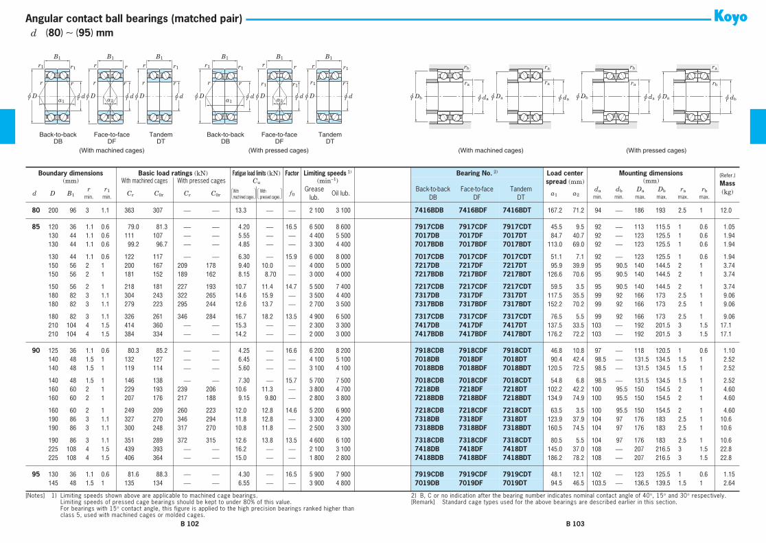
Back-to-backDB
Face-to-faceDF
(With machined cages) (With pressed cages)
TandemDT
Back-to-backDB
Face-to-faceDF
TandemDT
r
u D
rr
u D u d
rrB1
a2
rr
u D u d
r1r1
B1
a1
r
u d
rB1
r1 rr
u D u d
r1r1
B1
a2
rr
u D
r1r1
B1
a1u d
r
r
u D u d
r1
r1
B1
(With machined cages) (With pressed cages)
u Da u da
ra
u Da
ra
u Db u da
ra
u Db u da
rb rbra
u db
rb
ra
Angular contact ball bearings (matched pair)
80 200 96 3 1.1 363 307 ⎯ ⎯ 13.3 ⎯ ⎯ 2 100 3 100 7416BDB 7416BDF 7416BDT 167.2 71.2 94 ⎯ 186 193 2.5 1 12.0
85 120 36 1.1 0.6 79.0 81.3 ⎯ ⎯ 4.20 ⎯ 16.5 6 500 8 600 7917CDB 7917CDF 7917CDT 45.5 9.5 92 ⎯ 113 115.5 1 0.6 1.0585 130 44 1.1 0.6 111 107 ⎯ ⎯ 5.55 ⎯ ⎯ 4 400 5 500 7017DB 7017DF 7017DT 84.7 40.7 92 ⎯ 123 125.5 1 0.6 1.9485 130 44 1.1 0.6 99.2 96.7 ⎯ ⎯ 4.85 ⎯ ⎯ 3 300 4 400 7017BDB 7017BDF 7017BDT 113.0 69.0 92 ⎯ 123 125.5 1 0.6 1.94
85 130 44 1.1 0.6 122 117 ⎯ ⎯ 6.30 ⎯ 15.9 6 000 8 000 7017CDB 7017CDF 7017CDT 51.1 7.1 92 ⎯ 123 125.5 1 0.6 1.9485 150 56 2 1 200 167 209 178 9.40 10.0 ⎯ 4 000 5 000 7217DB 7217DF 7217DT 95.9 39.9 95 90.5 140 144.5 2 1 3.7485 150 56 2 1 181 152 189 162 8.15 8.70 ⎯ 3 000 4 000 7217BDB 7217BDF 7217BDT 126.6 70.6 95 90.5 140 144.5 2 1 3.74
85 150 56 2 1 218 181 227 193 10.7 11.4 14.7 5 500 7 400 7217CDB 7217CDF 7217CDT 59.5 3.5 95 90.5 140 144.5 2 1 3.7485 180 82 3 1.1 304 243 322 265 14.6 15.9 ⎯ 3 500 4 400 7317DB 7317DF 7317DT 117.5 35.5 99 92 166 173 2.5 1 9.0685 180 82 3 1.1 279 223 295 244 12.6 13.7 ⎯ 2 700 3 500 7317BDB 7317BDF 7317BDT 152.2 70.2 99 92 166 173 2.5 1 9.06
85 180 82 3 1.1 326 261 346 284 16.7 18.2 13.5 4 900 6 500 7317CDB 7317CDF 7317CDT 76.5 5.5 99 92 166 173 2.5 1 9.0685 210 104 4 1.5 414 360 ⎯ ⎯ 15.3 ⎯ ⎯ 2 300 3 300 7417DB 7417DF 7417DT 137.5 33.5 103 ⎯ 192 201.5 3 1.5 17.185 210 104 4 1.5 384 334 ⎯ ⎯ 14.2 ⎯ ⎯ 2 000 3 000 7417BDB 7417BDF 7417BDT 176.2 72.2 103 ⎯ 192 201.5 3 1.5 17.1
90 125 36 1.1 0.6 80.3 85.2 ⎯ ⎯ 4.25 ⎯ 16.6 6 200 8 200 7918CDB 7918CDF 7918CDT 46.8 10.8 97 ⎯ 118 120.5 1 0.6 1.1090 140 48 1.5 1 132 127 ⎯ ⎯ 6.45 ⎯ ⎯ 4 100 5 100 7018DB 7018DF 7018DT 90.4 42.4 98.5 ⎯ 131.5 134.5 1.5 1 2.5290 140 48 1.5 1 119 114 ⎯ ⎯ 5.60 ⎯ ⎯ 3 100 4 100 7018BDB 7018BDF 7018BDT 120.5 72.5 98.5 ⎯ 131.5 134.5 1.5 1 2.52
90 140 48 1.5 1 146 138 ⎯ ⎯ 7.30 ⎯ 15.7 5 700 7 500 7018CDB 7018CDF 7018CDT 54.8 6.8 98.5 ⎯ 131.5 134.5 1.5 1 2.5290 160 60 2 1 229 193 239 206 10.6 11.3 ⎯ 3 800 4 700 7218DB 7218DF 7218DT 102.2 42.2 100 95.5 150 154.5 2 1 4.6090 160 60 2 1 207 176 217 188 9.15 9.80 ⎯ 2 800 3 800 7218BDB 7218BDF 7218BDT 134.9 74.9 100 95.5 150 154.5 2 1 4.60
90 160 60 2 1 249 209 260 223 12.0 12.8 14.6 5 200 6 900 7218CDB 7218CDF 7218CDT 63.5 3.5 100 95.5 150 154.5 2 1 4.6090 190 86 3 1.1 327 270 346 294 11.8 12.8 ⎯ 3 300 4 200 7318DB 7318DF 7318DT 123.9 37.9 104 97 176 183 2.5 1 10.690 190 86 3 1.1 300 248 317 270 10.8 11.8 ⎯ 2 500 3 300 7318BDB 7318BDF 7318BDT 160.5 74.5 104 97 176 183 2.5 1 10.6
90 190 86 3 1.1 351 289 372 315 12.6 13.8 13.5 4 600 6 100 7318CDB 7318CDF 7318CDT 80.5 5.5 104 97 176 183 2.5 1 10.690 225 108 4 1.5 439 393 ⎯ ⎯ 16.2 ⎯ ⎯ 2 100 3 100 7418DB 7418DF 7418DT 145.0 37.0 108 ⎯ 207 216.5 3 1.5 22.890 225 108 4 1.5 406 364 ⎯ ⎯ 15.0 ⎯ ⎯ 1 800 2 800 7418BDB 7418BDF 7418BDT 186.2 78.2 108 ⎯ 207 216.5 3 1.5 22.8
95 130 36 1.1 0.6 81.6 88.3 ⎯ ⎯ 4.30 ⎯ 16.5 5 900 7 900 7919CDB 7919CDF 7919CDT 48.1 12.1 102 ⎯ 123 125.5 1 0.6 1.1595 145 48 1.5 1 135 134 ⎯ ⎯ 6.55 ⎯ ⎯ 3 900 4 800 7019DB 7019DF 7019DT 94.5 46.5 103.5 ⎯ 136.5 139.5 1.5 1 2.64
Boundary dimensions Basic load ratings (kN) Fatigue load limits (kN) Factor Limiting speeds 1) Bearing No. 2) Load centerspread (mm)
Mounting dimensions (Refer.)
Mass(kg)
(mm) With machined cages With pressed cages Cu (min−1) (mm)
d D B1r r1 Cr C0r Cr C0r f 0
Greaselub.
Oil lub.Back-to-back
DBFace-to-face
DFTandem
DTa1 a2
da db Da Db ra rbmin. min. min. min. max. max. max. max.
[Notes] 1) Limiting speeds shown above are applicable to machined cage bearings.Limiting speeds of pressed cage bearings should be kept to under 80% of this value.For bearings with 15° contact angle, this figure is applied to the high precision bearings ranked higher thanclass 5, used with machined cages or molded cages.
2) B, C or no indication after the bearing number indicates nominal contact angle of 40°, 15° and 30° respectively.[Remark] Standard cage types used for the above bearings are described earlier in this section.
With �machined cages
With �pressed cages
B 102 B 103
d (80) ∼ (95) mm

Back-to-backDB
Face-to-faceDF
(With machined cages) (With pressed cages)
TandemDT
Back-to-backDB
Face-to-faceDF
TandemDT
r
u D
rr
u D u d
rrB1
a2
rr
u D u d
r1r1
B1
a1
r
u d
rB1
r1 rr
u D u d
r1r1
B1
a2
rr
u D
r1r1
B1
a1u d
r
r
u D u d
r1
r1
B1
(With machined cages) (With pressed cages)
u Da u da
ra
u Da
ra
u Db u da
ra
u Db u da
rb rbra
u db
rb
ra
Angular contact ball bearings (matched pair)
95 145 48 1.5 1 121 121 ⎯ ⎯ 5.70 ⎯ ⎯ 2 900 3 900 7019BDB 7019BDF 7019BDT 126.4 78.4 103.5 ⎯ 136.5 139.5 1.5 1 2.6495 145 48 1.5 1 149 147 ⎯ ⎯ 7.40 ⎯ 15.9 5 300 7 100 7019CDB 7019CDF 7019CDT 56.7 8.7 103.5 ⎯ 136.5 139.5 1.5 1 2.6495 170 64 2.1 1.1 248 207 260 221 11.0 11.8 ⎯ 3 500 4 400 7219DB 7219DF 7219DT 108.5 44.5 107 102 158 163 2 1 5.56
95 170 64 2.1 1.1 224 188 235 201 9.55 10.2 ⎯ 2 700 3 500 7219BDB 7219BDF 7219BDT 143.2 79.2 107 102 158 163 2 1 5.5695 170 64 2.1 1.1 269 224 282 240 12.6 13.5 14.6 4 900 6 500 7219CDB 7219CDF 7219CDT 67.5 3.5 107 102 158 163 2 1 5.5695 200 90 3 1.1 350 298 371 325 12.7 13.8 ⎯ 3 200 4 000 7319DB 7319DF 7319DT 130.2 40.2 109 102 186 193 2.5 1 12.2
95 200 90 3 1.1 321 273 340 298 11.6 12.7 ⎯ 2 400 3 200 7319BDB 7319BDF 7319BDT 168.8 78.8 109 102 186 193 2.5 1 12.295 200 90 3 1.1 376 319 398 348 13.6 14.8 13.5 4 400 5 800 7319CDB 7319CDF 7319CDT 84.5 5.5 109 102 186 193 2.5 1 12.2
100 140 40 1.1 0.6 113 117 ⎯ ⎯ 5.65 ⎯ 16.3 5 500 7 400 7920CDB 7920CDF 7920CDT 52.1 12.1 107 ⎯ 133 135.5 1 0.6 1.55100 150 48 1.5 1 139 141 ⎯ ⎯ 6.75 ⎯ ⎯ 3 800 4 700 7020DB 7020DF 7020DT 96.2 48.2 108.5 ⎯ 141.5 144.5 1.5 1 2.74100 150 48 1.5 1 124 127 ⎯ ⎯ 5.90 ⎯ ⎯ 2 800 3 800 7020BDB 7020BDF 7020BDT 128.9 80.9 108.5 ⎯ 141.5 144.5 1.5 1 2.74
100 150 48 1.5 1 153 154 ⎯ ⎯ 7.65 ⎯ 16.0 5 200 6 900 7020CDB 7020CDF 7020CDT 57.5 9.5 108.5 ⎯ 141.5 144.5 1.5 1 2.74100 180 68 2.1 1.1 279 235 292 252 12.2 13.0 ⎯ 3 300 4 100 7220DB 7220DF 7220DT 115.4 47.4 112 ⎯ 168 173 2 1 6.64100 180 68 2.1 1.1 252 214 264 229 10.5 11.3 ⎯ 2 500 3 300 7220BDB 7220BDF 7220BDT 152.3 84.3 112 ⎯ 168 173 2 1 6.64
100 180 68 2.1 1.1 303 254 317 273 13.9 14.8 14.6 4 600 6 100 7220CDB 7220CDF 7220CDT 71.8 3.8 112 107 168 173 2 1 6.64100 215 94 3 1.1 373 323 421 387 13.2 15.9 ⎯ 2 900 3 600 7320DB 7320DF 7320DT 138.8 44.8 114 ⎯ 201 208 2.5 1 15.1100 215 94 3 1.1 342 297 386 356 12.2 14.6 ⎯ 2 200 2 900 7320BDB 7320BDF 7320BDT 180.4 86.4 114 ⎯ 201 208 2.5 1 15.1
100 215 94 3 1.1 400 346 451 415 14.2 17.0 13.4 4 000 5 300 7320CDB 7320CDF 7320CDT 89.6 4.4 114 107 201 208 2.5 1 15.1
105 145 40 1.1 0.6 115 123 ⎯ ⎯ 5.75 ⎯ 16.4 5 300 7 100 7921CDB 7921CDF 7921CDT 53.5 13.5 112 ⎯ 138 140.5 1 0.6 1.62105 160 52 2 1 162 164 ⎯ ⎯ 7.60 ⎯ ⎯ 3 500 4 400 7021DB 7021DF 7021DT 103.7 51.7 115 ⎯ 150 154.5 2 1 3.46105 160 52 2 1 145 148 ⎯ ⎯ 6.65 ⎯ ⎯ 2 600 3 500 7021BDB 7021BDF 7021BDT 137.2 85.2 115 ⎯ 150 154.5 2 1 3.46
105 160 52 2 1 178 179 ⎯ ⎯ 8.60 ⎯ 15.9 4 800 6 400 7021CDB 7021CDF 7021CDT 62.0 10.0 115 ⎯ 150 154.5 2 1 3.46105 190 72 2.1 1.1 303 265 ⎯ ⎯ 13.4 ⎯ ⎯ 3 100 3 900 7221DB 7221DF 7221DT 122.1 50.1 117 ⎯ 178 183 2 1 7.90105 190 72 2.1 1.1 275 241 ⎯ ⎯ 11.6 ⎯ ⎯ 2 300 3 100 7221BDB 7221BDF 7221BDT 161.0 89.0 117 ⎯ 178 183 2 1 7.90
105 190 72 2.1 1.1 330 287 ⎯ ⎯ 15.2 ⎯ 14.6 4 300 5 700 7221CDB 7221CDF 7221CDT 75.9 3.9 117 ⎯ 178 183 2 1 7.90105 225 98 3 1.1 422 386 ⎯ ⎯ 15.5 ⎯ ⎯ 2 800 3 500 7321DB 7321DF 7321DT 144.3 46.3 119 ⎯ 211 218 2.5 1 17.2105 225 98 3 1.1 387 355 ⎯ ⎯ 14.3 ⎯ ⎯ 2 100 2 800 7321BDB 7321BDF 7321BDT 187.5 89.5 119 ⎯ 211 218 2.5 1 17.2
Boundary dimensions Basic load ratings (kN) Fatigue load limits (kN) Factor Limiting speeds 1) Bearing No. 2) Load centerspread (mm)
Mounting dimensions (Refer.)
Mass(kg)
(mm) With machined cages With pressed cages Cu (min−1) (mm)
d D B1r r1 Cr C0r Cr C0r f 0
Greaselub.
Oil lub.Back-to-back
DBFace-to-face
DFTandem
DTa1 a2
da db Da Db ra rbmin. min. min. min. max. max. max. max.
[Notes] 1) Limiting speeds shown above are applicable to machined cage bearings.Limiting speeds of pressed cage bearings should be kept to under 80% of this value.For bearings with 15° contact angle, this figure is applied to the high precision bearings ranked higher thanclass 5, used with machined cages or molded cages.
2) B, C or no indication after the bearing number indicates nominal contact angle of 40°, 15° and 30° respectively.[Remark] Standard cage types used for the above bearings are described earlier in this section.
With �machined cages
With �pressed cages
B 104 B 105
d (95) ∼ (105) mm

Back-to-backDB
Face-to-faceDF
(With machined cages) (With pressed cages)
TandemDT
Back-to-backDB
Face-to-faceDF
TandemDT
r
u D
rr
u D u d
rrB1
a2
rr
u D u d
r1r1
B1
a1
r
u d
rB1
r1 rr
u D u d
r1r1
B1
a2
rr
u D
r1r1
B1
a1u d
r
r
u D u d
r1
r1
B1
(With machined cages) (With pressed cages)
u Da u da
ra
u Da
ra
u Db u da
ra
u Db u da
rb rbra
u db
rb
ra
Angular contact ball bearings (matched pair)
105 225 98 3 1.1 452 413 ⎯ ⎯ 16.6 ⎯ 13.4 3 900 5 100 7321CDB 7321CDF 7321CDT 93.2 4.8 119 ⎯ 211 218 2.5 1 17.2
110 150 40 1.1 0.6 117 129 ⎯ ⎯ 5.85 ⎯ 16.5 5 100 6 800 7922CDB 7922CDF 7922CDT 54.8 14.8 117 ⎯ 143 145.5 1 0.6 1.68110 170 56 2 1 187 186 ⎯ ⎯ 8.55 ⎯ ⎯ 3 300 4 200 7022DB 7022DF 7022DT 108.9 52.9 120 ⎯ 160 164.5 2 1 4.28110 170 56 2 1 167 167 ⎯ ⎯ 7.45 ⎯ ⎯ 2 500 3 300 7022BDB 7022BDF 7022BDT 145.5 89.5 120 ⎯ 160 164.5 2 1 4.28
110 170 56 2 1 205 203 ⎯ ⎯ 9.70 ⎯ 15.7 4 600 6 100 7022CDB 7022CDF 7022CDT 65.5 9.5 120 ⎯ 160 164.5 2 1 4.28110 200 76 2.1 1.1 329 297 ⎯ ⎯ 14.6 ⎯ ⎯ 3 000 3 700 7222DB 7222DF 7222DT 128.7 52.7 122 ⎯ 188 193 2 1 9.30110 200 76 2.1 1.1 298 270 ⎯ ⎯ 12.7 ⎯ ⎯ 2 200 3 000 7222BDB 7222BDF 7222BDT 169.7 93.7 122 ⎯ 188 193 2 1 9.30
110 200 76 2.1 1.1 357 321 ⎯ ⎯ 16.7 ⎯ 14.5 4 100 5 400 7222CDB 7222CDF 7222CDT 80.1 4.1 122 ⎯ 188 193 2 1 9.30110 240 100 3 1.1 472 452 ⎯ ⎯ 17.5 ⎯ ⎯ 2 600 3 200 7322DB 7322DF 7322DT 152.7 52.7 124 ⎯ 226 233 2.5 1 20.2110 240 100 3 1.1 433 416 ⎯ ⎯ 16.1 ⎯ ⎯ 1 900 2 600 7322BDB 7322BDF 7322BDT 199.3 99.3 124 ⎯ 226 233 2.5 1 20.2
110 240 100 3 1.1 505 484 ⎯ ⎯ 18.8 ⎯ 13.4 3 500 4 700 7322CDB 7322CDF 7322CDT 97.7 2.3 124 ⎯ 226 233 2.5 1 20.2
120 165 44 1.1 0.6 146 162 ⎯ ⎯ 7.10 ⎯ 16.5 4 700 6 200 7924CDB 7924CDF 7924CDT 60.2 16.2 127 ⎯ 158 160.5 1 0.6 2.30120 180 56 2 1 196 206 ⎯ ⎯ 9.00 ⎯ ⎯ 3 100 3 900 7024DB 7024DF 7024DT 114.6 58.6 130 ⎯ 170 174.5 2 1 4.54120 180 56 2 1 176 186 ⎯ ⎯ 7.85 ⎯ ⎯ 2 300 3 100 7024BDB 7024BDF 7024BDT 153.9 97.9 130 ⎯ 170 174.5 2 1 4.54
120 180 56 2 1 216 226 ⎯ ⎯ 10.2 ⎯ 16.0 4 300 5 700 7024CDB 7024CDF 7024CDT 68.2 12.2 130 ⎯ 170 174.5 2 1 4.54120 215 80 2.1 1.1 354 332 ⎯ ⎯ 15.7 ⎯ ⎯ 2 700 3 400 7224DB 7224DF 7224DT 137.0 57.0 132 ⎯ 203 208 2 1 11.0120 215 80 2.1 1.1 321 302 ⎯ ⎯ 13.6 ⎯ ⎯ 2 100 2 800 7224BDB 7224BDF 7224BDT 180.5 100.5 132 ⎯ 203 208 2 1 11.0
120 215 80 2.1 1.1 385 359 ⎯ ⎯ 17.9 ⎯ 14.6 3 800 5 000 7224CDB 7224CDF 7224CDT 85.0 5.0 132 ⎯ 203 208 2 1 11.0120 260 110 3 1.1 500 504 ⎯ ⎯ 18.9 ⎯ ⎯ 2 400 3 000 7324DB 7324DF 7324DT 164.7 54.7 134 ⎯ 246 253 2.5 1 25.2120 260 110 3 1.1 457 462 ⎯ ⎯ 17.3 ⎯ ⎯ 1 800 2 400 7324BDB 7324BDF 7324BDT 214.4 104.4 134 ⎯ 246 253 2.5 1 25.2
120 260 110 3 1.1 538 542 ⎯ ⎯ 20.3 ⎯ 13.7 3 300 4 400 7324CDB 7324CDF 7324CDT 105.9 4.1 134 ⎯ 246 253 2.5 1 25.2
130 180 48 1.5 1 177 200 ⎯ ⎯ 8.45 ⎯ 16.4 4 300 5 700 7926CDB 7926CDF 7926CDT 65.5 17.5 138.5 ⎯ 171.5 174.5 1.5 1 3.00130 200 66 2 1 238 251 ⎯ ⎯ 10.5 ⎯ ⎯ 2 800 3 500 7026DB 7026DF 7026DT 128.3 62.3 140 ⎯ 190 194.5 2 1 6.86130 200 66 2 1 213 226 ⎯ ⎯ 9.20 ⎯ ⎯ 2 100 2 800 7026BDB 7026BDF 7026BDT 171.5 105.5 140 ⎯ 190 194.5 2 1 6.86
130 200 66 2 1 262 274 ⎯ ⎯ 11.9 ⎯ 15.9 3 900 5 100 7026CDB 7026CDF 7026CDT 77.2 11.2 140 ⎯ 190 194.5 2 1 6.86130 230 80 3 1.1 398 395 ⎯ ⎯ 15.2 ⎯ ⎯ 2 500 3 200 7226DB 7226DF 7226DT 143.9 63.9 144 ⎯ 216 223 2.5 1 12.4
Boundary dimensions Basic load ratings (kN) Fatigue load limits (kN) Factor Limiting speeds 1) Bearing No. 2) Load centerspread (mm)
Mounting dimensions (Refer.)
Mass(kg)
(mm) With machined cages With pressed cages Cu (min−1) (mm)
d D B1r r1 Cr C0r Cr C0r f 0
Greaselub.
Oil lub.Back-to-back
DBFace-to-face
DFTandem
DTa1 a2
da db Da Db ra rbmin. min. min. min. max. max. max. max.
[Notes] 1) Limiting speeds shown above are applicable to machined cage bearings.Limiting speeds of pressed cage bearings should be kept to under 80% of this value.For bearings with 15° contact angle, this figure is applied to the high precision bearings ranked higher thanclass 5, used with machined cages or molded cages.
2) B, C or no indication after the bearing number indicates nominal contact angle of 40°, 15° and 30° respectively.[Remark] Standard cage types used for the above bearings are described earlier in this section.
With �machined cages
With �pressed cages
B 106 B 107
d (105) ∼ (130) mm

Back-to-backDB
Face-to-faceDF
(With machined cages) (With pressed cages)
TandemDT
Back-to-backDB
Face-to-faceDF
TandemDT
r
u D
rr
u D u d
rrB1
a2
rr
u D u d
r1r1
B1
a1
r
u d
rB1
r1 rr
u D u d
r1r1
B1
a2
rr
u D
r1r1
B1
a1u d
r
r
u D u d
r1
r1
B1
(With machined cages) (With pressed cages)
u Da u da
ra
u Da
ra
u Db u da
ra
u Db u da
rb rbra
u db
rb
ra
Angular contact ball bearings (matched pair)
130 230 80 3 1.1 360 360 ⎯ ⎯ 13.9 ⎯ ⎯ 1 900 2 500 7226BDB 7226BDF 7226BDT 191.0 111.0 144 ⎯ 216 223 2.5 1 12.4130 230 80 3 1.1 433 428 ⎯ ⎯ 16.5 ⎯ 14.7 3 500 4 700 7226CDB 7226CDF 7226CDT 88.2 8.2 144 ⎯ 216 223 2.5 1 12.4130 280 116 4 1.5 611 659 ⎯ ⎯ 23.7 ⎯ ⎯ 2 200 2 700 7326DB 7326DF 7326DT 177.5 61.5 148 ⎯ 262 271.5 3 1.5 30.8
130 280 116 4 1.5 507 536 ⎯ ⎯ 19.4 ⎯ ⎯ 1 600 2 200 7326BDB 7326BDF 7326BDT 230.0 114.0 148 ⎯ 262 271.5 3 1.5 30.8130 280 116 4 1.5 597 629 ⎯ ⎯ 22.7 ⎯ 13.7 3 000 4 000 7326CDB 7326CDF 7326CDT 112.9 3.1 148 ⎯ 262 271.5 3 1.5 30.8
140 190 48 1.5 1 179 210 ⎯ ⎯ 8.45 ⎯ 16.6 4 000 5 400 7928CDB 7928CDF 7928CDT 68.2 20.2 148.5 ⎯ 181.5 184.5 1.5 1 3.18140 210 66 2 1 243 265 ⎯ ⎯ 10.6 ⎯ ⎯ 2 600 3 300 7028DB 7028DF 7028DT 134.1 68.1 150 ⎯ 200 204.5 2 1 7.28140 210 66 2 1 217 237 ⎯ ⎯ 9.25 ⎯ ⎯ 2 000 2 600 7028BDB 7028BDF 7028BDT 179.8 113.8 150 ⎯ 200 204.5 2 1 7.28
140 210 66 2 1 268 290 ⎯ ⎯ 12.0 ⎯ 16.0 3 600 4 800 7028CDB 7028CDF 7028CDT 79.9 13.9 150 ⎯ 200 204.5 2 1 7.28140 250 84 3 1.1 443 468 ⎯ ⎯ 17.3 ⎯ ⎯ 2 300 2 900 7228DB 7228DF 7228DT 154.6 70.6 154 ⎯ 236 243 2.5 1 15.5140 250 84 3 1.1 401 426 ⎯ ⎯ 15.7 ⎯ ⎯ 1 700 2 300 7228BDB 7228BDF 7228BDT 205.6 121.6 154 ⎯ 236 243 2.5 1 15.5
140 250 84 3 1.1 483 508 ⎯ ⎯ 18.8 ⎯ 14.8 3 200 4 300 7228CDB 7228CDF 7228CDT 94.2 10.2 154 ⎯ 236 243 2.5 1 15.5140 300 124 4 1.5 668 748 ⎯ ⎯ 26.1 ⎯ ⎯ 2 000 2 500 7328DB 7328DF 7328DT 189.0 65.0 158 ⎯ 282 291.5 3 1.5 37.6140 300 124 4 1.5 613 688 ⎯ ⎯ 24.0 ⎯ ⎯ 1 500 2 000 7328BDB 7328BDF 7328BDT 246.6 122.6 158 ⎯ 282 291.5 3 1.5 37.6
140 300 124 4 1.5 717 802 ⎯ ⎯ 27.9 ⎯ 13.4 2 800 3 700 7328CDB 7328CDF 7328CDT 120.9 3.1 158 ⎯ 282 291.5 3 1.5 37.6
150 210 56 2 1 241 263 ⎯ ⎯ 10.9 ⎯ 16.3 3 700 4 900 7930CDB 7930CDF 7930CDT 76.2 20.2 160 ⎯ 200 204.5 2 1 4.94150 225 70 2.1 1.1 278 308 ⎯ ⎯ 11.9 ⎯ ⎯ 2 400 3 000 7030DB 7030DF 7030DT 144.2 74.2 162 ⎯ 213 218 2 1 8.86150 225 70 2.1 1.1 249 275 ⎯ ⎯ 10.4 ⎯ ⎯ 1 800 2 400 7030BDB 7030BDF 7030BDT 192.3 122.3 162 ⎯ 213 218 2 1 8.86
150 225 70 2.1 1.1 306 337 ⎯ ⎯ 13.4 ⎯ 16.1 3 300 4 400 7030CDB 7030CDF 7030CDT 85.6 15.6 162 ⎯ 213 218 2 1 8.86150 270 90 3 1.1 504 560 ⎯ ⎯ 19.9 ⎯ ⎯ 2 100 2 700 7230DB 7230DF 7230DT 166.3 76.3 164 ⎯ 256 263 2.5 1 19.5150 270 90 3 1.1 456 509 ⎯ ⎯ 18.1 ⎯ ⎯ 1 600 2 100 7230BDB 7230BDF 7230BDT 221.2 131.2 164 ⎯ 256 263 2.5 1 19.5
150 270 90 3 1.1 549 607 ⎯ ⎯ 21.6 ⎯ 14.7 2 900 3 900 7230CDB 7230CDF 7230CDT 101.3 11.3 164 ⎯ 256 263 2.5 1 19.5150 320 130 4 1.5 706 829 ⎯ ⎯ 27.9 ⎯ ⎯ 1 900 2 300 7330DB 7330DF 7330DT 200.7 70.7 168 ⎯ 302 311.5 3 1.5 44.8150 320 130 4 1.5 645 760 ⎯ ⎯ 25.6 ⎯ ⎯ 1 400 1 900 7330BDB 7330BDF 7330BDT 262.2 132.2 168 ⎯ 302 311.5 3 1.5 44.8
150 320 130 4 1.5 760 891 ⎯ ⎯ 30.0 ⎯ 13.7 2 600 3 400 7330CDB 7330CDF 7330CDT 128.0 2.0 168 ⎯ 302 311.5 3 1.5 44.8
160 220 56 2 1 245 289 ⎯ ⎯ 10.9 ⎯ 16.5 3 500 4 700 7932CDB 7932CDF 7932CDT 78.9 22.9 170 ⎯ 210 214.5 2 1 5.20
Boundary dimensions Basic load ratings (kN) Fatigue load limits (kN) Factor Limiting speeds 1) Bearing No. 2) Load centerspread (mm)
Mounting dimensions (Refer.)
Mass(kg)
(mm) With machined cages With pressed cages Cu (min−1) (mm)
d D B1r r1 Cr C0r Cr C0r f 0
Greaselub.
Oil lub.Back-to-back
DBFace-to-face
DFTandem
DTa1 a2
da db Da Db ra rbmin. min. min. min. max. max. max. max.
[Notes] 1) Limiting speeds shown above are applicable to machined cage bearings.Limiting speeds of pressed cage bearings should be kept to under 80% of this value.For bearings with 15° contact angle, this figure is applied to the high precision bearings ranked higher thanclass 5, used with machined cages or molded cages.
2) B, C or no indication after the bearing number indicates nominal contact angle of 40°, 15° and 30° respectively.[Remark] Standard cage types used for the above bearings are described earlier in this section.
With �machined cages
With �pressed cages
B 108 B 109
d (130) ∼ (160) mm

Back-to-backDB
Face-to-faceDF
(With machined cages) (With pressed cages)
TandemDT
Back-to-backDB
Face-to-faceDF
TandemDT
r
u D
rr
u D u d
rrB1
a2
rr
u D u d
r1r1
B1
a1
r
u d
rB1
r1 rr
u D u d
r1r1
B1
a2
rr
u D
r1r1
B1
a1u d
r
r
u D u d
r1
r1
B1
(With machined cages) (With pressed cages)
u Da u da
ra
u Da
ra
u Db u da
ra
u Db u da
rb rbra
u db
rb
ra
Angular contact ball bearings (matched pair)
160 240 76 2.1 1.1 315 353 ⎯ ⎯ 13.3 ⎯ ⎯ 2 300 2 800 7032DB 7032DF 7032DT 153.5 77.5 172 ⎯ 228 233 2 1 10.9160 240 76 2.1 1.1 282 316 ⎯ ⎯ 11.6 ⎯ ⎯ 1 700 2 300 7032BDB 7032BDF 7032BDT 205.8 129.8 172 ⎯ 228 233 2 1 10.9160 240 76 2.1 1.1 347 386 ⎯ ⎯ 15.0 ⎯ 16.0 3 100 4 100 7032CDB 7032CDF 7032CDT 91.6 15.6 172 ⎯ 228 233 2 1 10.9
160 290 96 3 1.1 468 525 ⎯ ⎯ 18.1 ⎯ ⎯ 2 000 2 500 7232DB 7232DF 7232DT 177.9 81.9 174 ⎯ 276 283 2.5 1 24.2160 290 96 3 1.1 482 557 ⎯ ⎯ 19.2 ⎯ ⎯ 1 500 2 000 7232BDB 7232BDF 7232BDT 236.8 140.8 174 ⎯ 276 283 2.5 1 24.2160 290 96 3 1.1 511 665 ⎯ ⎯ 19.7 ⎯ 15.2 2 700 3 600 7232CDB 7232CDF 7232CDT 108.3 12.3 174 ⎯ 276 283 2.5 1 24.2
160 340 136 4 1.5 741 909 ⎯ ⎯ 29.7 ⎯ ⎯ 1 700 2 200 7332DB 7332DF 7332DT 212.3 76.3 178 ⎯ 322 331.5 3 1.5 52.8160 340 136 4 1.5 675 831 ⎯ ⎯ 27.2 ⎯ ⎯ 1 300 1 700 7332BDB 7332BDF 7332BDT 277.8 141.8 178 ⎯ 322 331.5 3 1.5 52.8160 340 136 4 1.5 800 980 ⎯ ⎯ 32.0 ⎯ 14.0 2 400 3 200 7332CDB 7332CDF 7332CDT 135.0 1.0 168.5 ⎯ 322 331.5 3 1.5 52.8
170 230 56 2 1 255 302 ⎯ ⎯ 11.5 ⎯ 16.6 3 100 4 100 7934CDB 7934CDF 7934CDT 81.6 25.6 180 ⎯ 220 224.5 2 1 6.42170 260 84 2.1 1.1 377 429 ⎯ ⎯ 15.8 ⎯ ⎯ 2 100 2 600 7034DB 7034DF 7034DT 166.2 82.2 182 ⎯ 248 253 2 1 15.2170 260 84 2.1 1.1 338 386 ⎯ ⎯ 13.8 ⎯ ⎯ 1 600 2 100 7034BDB 7034BDF 7034BDT 222.4 138.4 182 ⎯ 248 253 2 1 15.5
170 260 84 2.1 1.1 415 469 ⎯ ⎯ 17.9 ⎯ 15.9 2 900 3 800 7034CDB 7034CDF 7034CDT 99.6 15.6 182 ⎯ 248 253 2 1 15.1170 310 104 4 1.5 552 661 ⎯ ⎯ 22.0 ⎯ ⎯ 1 800 2 300 7234DB 7234DF 7234DT 190.6 86.6 188 ⎯ 292 301.5 3 1.5 30.2170 310 104 4 1.5 497 600 ⎯ ⎯ 20.0 ⎯ ⎯ 1 400 1 800 7234BDB 7234BDF 7234BDT 253.4 149.4 188 ⎯ 292 301.5 3 1.5 30.2
170 310 104 4 1.5 603 719 ⎯ ⎯ 24.0 ⎯ 15.1 2 500 3 300 7234CDB 7234CDF 7234CDT 116.3 12.3 188 ⎯ 292 301.5 3 1.5 30.2170 360 144 4 1.5 789 969 ⎯ ⎯ 30.7 ⎯ ⎯ 1 600 2 000 7334DB 7334DF 7334DT 225.0 81.0 188 ⎯ 342 351.5 3 1.5 62.4170 360 144 4 1.5 721 888 ⎯ ⎯ 28.2 ⎯ ⎯ 1 200 1 600 7334BDB 7334BDF 7334BDT 294.4 150.4 188 ⎯ 342 351.5 3 1.5 62.4
170 360 144 4 1.5 849 1 040 ⎯ ⎯ 33.1 ⎯ 13.8 2 200 3 000 7334CDB 7334CDF 7334CDT 143.0 1.0 188 ⎯ 342 351.5 3 1.5 62.4
180 250 66 2 1 325 375 ⎯ ⎯ 14.1 ⎯ 16.4 2 800 3 700 7936CDB 7936CDF 7936CDT 90.6 24.6 190 ⎯ 240 244.5 2 1 9.36180 280 92 2.1 1.1 430 506 ⎯ ⎯ 18.3 ⎯ ⎯ 1 900 2 400 7036DB 7036DF 7036DT 178.8 86.8 192 ⎯ 268 273 2 1 20.2180 280 92 2.1 1.1 385 457 ⎯ ⎯ 15.9 ⎯ ⎯ 1 400 1 900 7036BDB 7036BDF 7036BDT 239.0 147.0 192 ⎯ 268 273 2 1 20.4
180 280 92 2.1 1.1 473 553 ⎯ ⎯ 20.7 ⎯ 15.7 2 600 3 500 7036CDB 7036CDF 7036CDT 107.6 15.6 192 ⎯ 268 273 2 1 19.9180 320 104 4 1.5 596 724 ⎯ ⎯ 23.7 ⎯ ⎯ 1 700 2 200 7236DB 7236DF 7236DT 196.3 92.3 198 ⎯ 302 311.5 3 1.5 31.4180 320 104 4 1.5 538 657 ⎯ ⎯ 21.5 ⎯ ⎯ 1 300 1 700 7236BDB 7236BDF 7236BDT 261.8 157.8 198 ⎯ 302 311.5 3 1.5 31.4
180 320 104 4 1.5 650 786 ⎯ ⎯ 25.7 ⎯ 14.9 2 400 3 200 7236CDB 7236CDF 7236CDT 119.0 15.0 198 ⎯ 302 311.5 3 1.5 31.4180 380 150 4 1.5 831 1 070 ⎯ ⎯ 33.0 ⎯ ⎯ 1 500 1 900 7336DB 7336DF 7336DT 236.7 86.7 198 ⎯ 362 371.5 3 1.5 80.0
Boundary dimensions Basic load ratings (kN) Fatigue load limits (kN) Factor Limiting speeds 1) Bearing No. 2) Load centerspread (mm)
Mounting dimensions (Refer.)
Mass(kg)
(mm) With machined cages With pressed cages Cu (min−1) (mm)
d D B1r r1 Cr C0r Cr C0r f 0
Greaselub.
Oil lub.Back-to-back
DBFace-to-face
DFTandem
DTa1 a2
da db Da Db ra rbmin. min. min. min. max. max. max. max.
[Notes] 1) Limiting speeds shown above are applicable to machined cage bearings.Limiting speeds of pressed cage bearings should be kept to under 80% of this value.For bearings with 15° contact angle, this figure is applied to the high precision bearings ranked higher thanclass 5, used with machined cages or molded cages.
2) B, C or no indication after the bearing number indicates nominal contact angle of 40°, 15° and 30° respectively.[Remark] Standard cage types used for the above bearings are described earlier in this section.
With �machined cages
With �pressed cages
B 110 B 111
d (160) ∼ (180) mm

Back-to-backDB
Face-to-faceDF
(With machined cages) (With pressed cages)
TandemDT
Back-to-backDB
Face-to-faceDF
TandemDT
r
u D
rr
u D u d
rrB1
a2
rr
u D u d
r1r1
B1
a1
r
u d
rB1
r1 rr
u D u d
r1r1
B1
a2
rr
u D
r1r1
B1
a1u d
r
r
u D u d
r1
r1
B1
(With machined cages) (With pressed cages)
u Da u da
ra
u Da
ra
u Db u da
ra
u Db u da
rb rbra
u db
rb
ra
Angular contact ball bearings (matched pair)
180 380 150 4 1.5 757 976 ⎯ ⎯ 30.1 ⎯ ⎯ 1 100 1 500 7336BDB 7336BDF 7336BDT 309.9 159.9 198 ⎯ 362 371.5 3 1.5 80.0
190 260 66 2 1 322 394 ⎯ ⎯ 13.7 ⎯ 16.5 2 700 3 600 7938CDB 7938CDF 7938CDT 93.3 27.3 200 ⎯ 250 254.5 2 1 9.66190 290 92 2.1 1.1 441 535 ⎯ ⎯ 18.7 ⎯ ⎯ 1 800 2 300 7038DB 7038DF 7038DT 184.6 92.6 202 ⎯ 278 283 2 1 21.6190 290 92 2.1 1.1 395 483 ⎯ ⎯ 16.3 ⎯ ⎯ 1 400 1 800 7038BDB 7038BDF 7038BDT 247.4 155.4 202 ⎯ 278 283 2 1 21.6
190 290 92 2.1 1.1 485 585 ⎯ ⎯ 21.1 ⎯ 15.9 2 500 3 300 7038CDB 7038CDF 7038CDT 110.3 18.3 202 ⎯ 278 283 2 1 21.6190 340 110 4 1.5 616 779 ⎯ ⎯ 24.7 ⎯ ⎯ 1 600 2 000 7238DB 7238DF 7238DT 208.0 98.0 208 ⎯ 322 331.5 3 1.5 37.6190 340 110 4 1.5 555 706 ⎯ ⎯ 22.4 ⎯ ⎯ 1 200 1 600 7238BDB 7238BDF 7238BDT 277.4 167.4 208 ⎯ 322 331.5 3 1.5 37.6
190 340 110 4 1.5 673 848 ⎯ ⎯ 26.9 ⎯ 15.1 2 200 3 000 7238CDB 7238CDF 7238CDT 126.0 16.0 208 ⎯ 322 331.5 3 1.5 37.6190 400 156 5 2 914 1 200 ⎯ ⎯ 36.0 ⎯ ⎯ 1 400 1 800 7338DB 7338DF 7338DT 248.3 92.3 212 ⎯ 378 390 4 2 91.0190 400 156 5 2 835 1 100 ⎯ ⎯ 33.0 ⎯ ⎯ 1 100 1 400 7338BDB 7338BDF 7338BDT 325.5 169.5 212 ⎯ 378 390 4 2 91.0
200 280 76 2.1 1.1 415 509 ⎯ ⎯ 17.4 ⎯ 16.3 2 500 3 300 7940CDB 7940CDF 7940CDT 102.3 26.3 212 ⎯ 268 273 2 1 13.7200 310 102 2.1 1.1 495 618 ⎯ ⎯ 20.0 ⎯ ⎯ 1 700 2 100 7040DB 7040DF 7040DT 198.3 96.3 212 ⎯ 298 303 2 1 25.4200 310 102 2.1 1.1 443 558 ⎯ ⎯ 18.1 ⎯ ⎯ 1 300 1 700 7040BDB 7040BDF 7040BDT 265.0 163.0 212 ⎯ 298 303 2 1 25.4
200 310 102 2.1 1.1 544 676 ⎯ ⎯ 21.9 ⎯ 15.7 2 300 3 100 7040CDB 7040CDF 7040CDT 119.3 17.3 212 ⎯ 298 303 2 1 25.4200 360 116 4 1.5 658 847 ⎯ ⎯ 26.2 ⎯ ⎯ 1 500 1 900 7240DB 7240DF 7240DT 219.7 103.7 218 ⎯ 342 351.5 3 1.5 44.8200 360 116 4 1.5 593 768 ⎯ ⎯ 23.7 ⎯ ⎯ 1 100 1 500 7240BDB 7240BDF 7240BDT 292.9 176.9 218 ⎯ 342 351.5 3 1.5 44.8
200 360 116 4 1.5 718 921 ⎯ ⎯ 28.4 ⎯ 15.1 2 100 2 800 7240CDB 7240CDF 7240CDT 133.0 17.0 218 ⎯ 342 351.5 3 1.5 44.8200 420 160 5 2 964 1 320 ⎯ ⎯ 38.6 ⎯ ⎯ 1 300 1 700 7340DB 7340DF 7340DT 259.0 99.0 222 ⎯ 398 410 4 2 104200 420 160 5 2 878 1 200 ⎯ ⎯ 35.3 ⎯ ⎯ 1 000 1 300 7340BDB 7340BDF 7340BDT 340.1 180.1 222 ⎯ 398 410 4 2 104
220 340 112 3 1.1 543 705 ⎯ ⎯ 21.8 ⎯ ⎯ 1 500 1 900 7044DB 7044DF ⎯ 217.8 105.8 234 ⎯ 326 333 2.5 1 37.0220 340 112 3 1.1 486 636 ⎯ ⎯ 19.6 ⎯ ⎯ 1 100 1 500 7044BDB 7044BDF ⎯ 290.9 178.9 234 ⎯ 326 333 2.5 1 37.8
240 360 112 3 1.1 591 751 ⎯ ⎯ 24.6 ⎯ ⎯ 1 400 1 700 7048DB 7048DF ⎯ 229.2 117.2 254 ⎯ 346 353 2.5 1 39.4240 360 112 3 1.1 528 677 ⎯ ⎯ 22.2 ⎯ ⎯ 1 000 1 400 7048BDB 7048BDF ⎯ 307.7 195.7 254 ⎯ 346 353 2.5 1 40.2240 440 144 4 1.5 819 1 190 ⎯ ⎯ 33.4 ⎯ ⎯ 1 200 1 500 7248DB 7248DF ⎯ 268.3 124.3 258 ⎯ 422 431.5 3 1.5 104
240 440 144 4 1.5 736 1 080 ⎯ ⎯ 30.2 ⎯ ⎯ 890 1 200 7248BDB 7248BDF ⎯ 357.3 213.3 258 ⎯ 422 431.5 3 1.5 106
Boundary dimensions Basic load ratings (kN) Fatigue load limits (kN) Factor Limiting speeds 1) Bearing No. 2) Load centerspread (mm)
Mounting dimensions (Refer.)
Mass(kg)
(mm) With machined cages With pressed cages Cu (min−1) (mm)
d D B1r r1 Cr C0r Cr C0r f 0
Greaselub.
Oil lub.Back-to-back
DBFace-to-face
DFTandem
DTa1 a2
da db Da Db ra rbmin. min. min. min. max. max. max. max.
[Notes] 1) Limiting speeds shown above are applicable to machined cage bearings.Limiting speeds of pressed cage bearings should be kept to under 80% of this value.For bearings with 15° contact angle, this figure is applied to the high precision bearings ranked higher thanclass 5, used with machined cages or molded cages.
2) B, C or no indication after the bearing number indicates nominal contact angle of 40°, 15° and 30° respectively.[Remark] Standard cage types used for the above bearings are described earlier in this section.
With �machined cages
With �pressed cages
B 112 B 113
d (180) ∼ 240 mm

Back-to-backDB
Face-to-faceDF
(With machined cages) (With pressed cages)
TandemDT
Back-to-backDB
Face-to-faceDF
TandemDT
r
u D
rr
u D u d
rrB1
a2
rr
u D u d
r1r1
B1
a1
r
u d
rB1
r1 rr
u D u d
r1r1
B1
a2
rr
u D
r1r1
B1
a1u d
r
r
u D u d
r1
r1
B1
(With machined cages) (With pressed cages)
u Da u da
ra
u Da
ra
u Db u da
ra
u Db u da
rb rbra
u db
rb
ra
Angular contact ball bearings (matched pair)
260 400 130 4 1.5 661 956 ⎯ ⎯ 27.1 ⎯ ⎯ 1 200 1 500 7052DB 7052DF ⎯ 256.7 126.7 278 ⎯ 382 391.5 3 1.5 57.4260 400 130 4 1.5 592 862 ⎯ ⎯ 24.4 ⎯ ⎯ 910 1 200 7052BDB 7052BDF ⎯ 341.9 211.9 278 ⎯ 382 391.5 3 1.5 58.6
280 420 130 4 1.5 675 1 010 ⎯ ⎯ 27.9 ⎯ ⎯ 1 100 1 400 7056DB 7056DF ⎯ 267.1 137.1 298 ⎯ 402 411.5 3 1.5 60.8280 420 130 4 1.5 623 906 ⎯ ⎯ 26.2 ⎯ ⎯ 850 1 100 7056BDB 7056BDF ⎯ 358.7 228.7 298 ⎯ 402 411.5 3 1.5 62.0
300 460 148 4 1.5 866 1 360 ⎯ ⎯ 36.0 ⎯ ⎯ 1 000 1 300 7060DB 7060DF ⎯ 293.4 145.4 318 ⎯ 442 451.5 3 1.5 87.4300 460 148 4 1.5 776 1 230 ⎯ ⎯ 32.5 ⎯ ⎯ 770 1 000 7060BDB 7060BDF ⎯ 392.9 244.9 318 ⎯ 442 451.5 3 1.5 89.8
320 480 148 4 1.5 887 1 440 ⎯ ⎯ 37.3 ⎯ ⎯ 950 1 200 7064DB 7064DF ⎯ 304.9 156.9 338 ⎯ 462 471.5 3 1.5 92.0320 480 148 4 1.5 795 1 300 ⎯ ⎯ 33.6 ⎯ ⎯ 710 950 7064BDB 7064BDF ⎯ 409.6 261.6 338 ⎯ 462 471.5 3 1.5 94.4
340 520 164 5 2 1 020 1 720 ⎯ ⎯ 42.9 ⎯ ⎯ 860 1 100 7068DB 7068DF ⎯ 330.3 166.3 362 ⎯ 498 510 4 2 124340 520 164 5 2 914 1 550 ⎯ ⎯ 38.7 ⎯ ⎯ 640 860 7068BDB 7068BDF ⎯ 442.8 278.8 362 ⎯ 498 510 4 2 127
360 540 164 5 2 1 050 1 830 ⎯ ⎯ 44.5 ⎯ ⎯ 800 1 000 7072DB 7072DF ⎯ 341.8 177.8 382 ⎯ 518 530 4 2 129360 540 164 5 2 937 1 650 ⎯ ⎯ 40.1 ⎯ ⎯ 600 800 7072BDB 7072BDF ⎯ 459.6 295.6 382 ⎯ 518 530 4 2 132
380 560 164 5 2 1 070 1 930 ⎯ ⎯ 46.0 ⎯ ⎯ 750 940 7076DB 7076DF ⎯ 353.4 189.4 402 ⎯ 538 550 4 2 134380 560 164 5 2 959 1 740 ⎯ ⎯ 41.5 ⎯ ⎯ 560 750 7076BDB 7076BDF ⎯ 476.4 312.4 402 ⎯ 538 550 4 2 138
Boundary dimensions Basic load ratings (kN) Fatigue load limits (kN) Factor Limiting speeds 1) Bearing No. 2) Load centerspread (mm)
Mounting dimensions (Refer.)
Mass(kg)
(mm) With machined cages With pressed cages Cu (min−1) (mm)
d D B1r r1 Cr C0r Cr C0r f 0
Greaselub.
Oil lub.Back-to-back
DBFace-to-face
DFTandem
DTa1 a2
da db Da Db ra rbmin. min. min. min. max. max. max. max.
[Notes] 1) Limiting speeds shown above are applicable to machined cage bearings.Limiting speeds of pressed cage bearings should be kept to under 80% of this value.For bearings with 15° contact angle, this figure is applied to the high precision bearings ranked higher thanclass 5, used with machined cages or molded cages.
2) B, C or no indication after the bearing number indicates nominal contact angle of 40°, 15° and 30° respectively.[Remark] Standard cage types used for the above bearings are described earlier in this section.
With �machined cages
With �pressed cages
B 114 B 115
d 260 ∼ 380 mm
[Notes] 1) Limiting speeds shown above are applicable to machined cage bearings.Limiting speeds of pressed cage bearings should be kept to under 80% of this value.For bearings with 15° contact angle, this figure is applied to the high precision bearings ranked higher thanclass 5, used with machined cages or molded cages.
2) B or no indication after the bearing number indicates nominal contact angle of 40° and 30° respectively.[Remark] Standard cage types used for the above bearings are described earlier in this section.

r
r
u D u d
r
r
u D u dZ RS
ZZ 2RS
Open Shielded Contactsealed
32, 33 series(With filling slot)
52, 53 series(Without filling slot)
B B
u Da u da
ra
u Da u da
ra
ra ra
a a
Double-row angular contact ball bearings
Boundary dimensions Basic load ratings
(kN)
Fatigue load limits
(kN)
Limiting speeds
(min
−
1
)
Bearing No.
Load centerspread
(mm)
Open
a
Mounting dimensions
1)
(Refer.)
Mass
(kg)
(mm)
Open
Shielded/sealed
C
u
Grease lub. Oil lub.
(mm)
d D Br
C
r
C
0r
C
r
C
0r
(Open)
(Shielded/sealed) (RS, 2RS)
Open Shielded Sealed
d
a
D
a
r
a
min. min. max. max. max.
10
30 14.3 0.6 9.15 5.35
⎯ ⎯
0.280
⎯
15 000
⎯
20 000
3200
⎯ ⎯
19.5 14.5
⎯
25.5 0.6 0.052
12
32 15.9 0.6 12.1 7.15
⎯ ⎯
0.370
⎯
14 000
⎯
18 000
3201
⎯ ⎯
21.7 16.5
⎯
27.5 0.6 0.063
15
35 15.9 0.6 12.1 7.45
⎯ ⎯
0.390
⎯
12 000
⎯
16 000
3202
⎯ ⎯
23.6 19.5
⎯
30.5 0.6 0.072
15
42 19 1 19.0 11.9
⎯ ⎯
0.610
⎯
10 000
⎯
14 000
3302
⎯ ⎯
27.6 20.5
⎯
36.5 1 0.132
17
40 17.5 0.6 17.2 10.8
⎯ ⎯
0.560
⎯
11 000
⎯
14 000
3203
⎯ ⎯
26.6 21.5
⎯
35.5 0.6 0.100
17
40 17.5 0.6 16.5 8.15 15.9 8.35 0.420 0.430 11 000 11 000 14 000
5203 5203 ZZ 5203 2RS
20.0 21.5 23.5 35.5 0.6 0.091
17
47 22.2 1 23.0 17.1
⎯ ⎯
0.760
⎯
9 400
⎯
13 000
3303
⎯ ⎯
31.0 22.5
⎯
41.5 1 0.192
20
47 20.6 1 21.5 15.0
⎯ ⎯
0.770
⎯
9 000
⎯
12 000
3204
⎯ ⎯
31.5 25.5
⎯
41.5 1 0.170
20
47 20.6 1 24.6 12.5 20.0 10.8 0.640 0.560 8 800 8 800 12 000
5204 5204 ZZ 5204 2RS
23.5 25.5 26.6 41.5 1 0.158
20
52 22.2 1.1 26.0 18.4
⎯ ⎯
0.950
⎯
8 200
⎯
11 000
3304
⎯ ⎯
33.8 27
⎯
45 1 0.230
20
52 22.2 1.1 30.9 15.0 24.7 12.8 0.780 0.660 8 300 8 300 11 000
5304 5304 ZZ 5304 2RS
25.9 27 28.3 45 1 0.230
25
52 20.6 1 23.7 18.2
⎯ ⎯
0.940
⎯
7 800
⎯
10 000
3205
⎯ ⎯
34.4 30.5
⎯
46.5 1 0.190
25
52 20.6 1 26.7 14.8 23.6 13.8 0.760 0.710 7 700 7 700 10 000
5205 5205 ZZ 5205 2RS
26.1 30.5 32.3 46.5 1 0.190
25
62 25.4 1.1 36.2 26.5
⎯ ⎯
1.35
⎯
6 800
⎯
9 100
3305
⎯ ⎯
40.5 32
⎯
55 1 0.369
25
62 25.4 1.1 40.9 20.8 34.3 18.5 1.05 0.960 6 900 6 900 9 200
5305 5305 ZZ 5305 2RS
31.1 32 33.4 55 1 0.340
30
62 23.8 1 34.1 27.0
⎯ ⎯
1.40
⎯
6 500
⎯
8 700
3206
⎯ ⎯
40.7 35.5
⎯
56.5 1 0.320
30
62 23.8 1 37.2 21.3 31.7 18.3 1.10 0.950 6 400 6 400 8 600
5206 5206 ZZ 5206 2RS
30.8 35.5 38.6 56.5 1 0.290
30
72 30.2 1.1 47.7 36.1
⎯ ⎯
1.85
⎯
5 800
⎯
7 800
3306
⎯ ⎯
47.2 37
⎯
65 1 0.585
30
72 30.2 1.1 51.2 28.5 42.9 25.2 1.45 1.30 5 800 5 800 7 700
5306 5306 ZZ 5306 2RS
36.2 37 41.3 65 1 0.510
35
72 27 1.1 46.0 37.5
⎯ ⎯
1.95
⎯
5 600
⎯
7 500
3207
⎯ ⎯
46.9 42
⎯
65 1 0.480
35
72 27 1.1 49.0 29.0 39.7 24.6 1.50 1.25 5 500 5 500 7 300
5207 5207 ZZ 5207 2RS
36.1 42 43.9 65 1 0.430
35
80 34.9 1.5 60.7 46.8
⎯ ⎯
2.40
⎯
5 200
⎯
7 000
3307
⎯ ⎯
53.4 43.5
⎯
71.5 1.5 0.816
35
80 34.9 1.5 64.0 36.2 57.6 32.8 1.85 1.70 5 100 5 100 6 800
5307 5307 ZZ 5307 2RS
41.0 43.5 45.5 71.5 1.5 0.790
40
80 30.2 1.1 52.4 43.9
⎯ ⎯
2.25
⎯
5 000
⎯
6 700
3208
⎯ ⎯
52.6 47
⎯
73 1 0.650
40
80 30.2 1.1 55.5 33.6 45.7 29.1 1.75 1.50 5 000 5 000 6 700
5208 5208 ZZ 5208 2RS
39.2 47 49.5 73 1 0.570
[Note] 1) The maximum value of
d
a
is applied to shielded and sealed type bearings. [Remark] Standard cage types used for the above bearings are described earlier in this section.
OpenZ, ZZ
OpenZ
B 116 B 117
d
10
∼
(
40
)
mm

r
r
u D u d
r
r
u D u dZ RS
ZZ 2RS
Open Shielded Contactsealed
32, 33 series(With filling slot)
52, 53 series(Without filling slot)
B B
u Da u da
ra
u Da u da
ra
ra ra
a a
Double-row angular contact ball bearings
40
90 36.5 1.5 67.6 53.8
⎯ ⎯
2.80
⎯
4 600
⎯
6 100
3308
⎯ ⎯
58.9 48.5
⎯
81.5 1.5 1.07
40
90 36.5 1.5 78.3 45.4 64.3 37.8 2.35 1.95 4 600 4 600 6 100
5308 5308 ZZ 5308 2RS
44.9 48.5 52.1 81.5 1.5 1.05
45
85 30.2 1.1 56.8 51.4
⎯ ⎯
2.65
⎯
4 600
⎯
6 100
3209
⎯ ⎯
56.3 52
⎯
78 1 0.710
45
85 30.2 1.1 62.3 38.4 52.1 33.9 2.00 1.75 4 600 4 600 6 100
5209 5209 ZZ 5209 2RS
42.2 52 55.3 78 1 0.620
45
100 39.7 1.5 82.6 67.3
⎯ ⎯
3.50
⎯
4 100
⎯
5 500
3309
⎯ ⎯
65.6 53.5
⎯
91.5 1.5 1.42
45
100 39.7 1.5 93.8 55.7 86.1 51.4 2.90 2.65 4 100 4 100 5 500
5309 5309 ZZ 5309 2RS
51.0 53.5 58.2 91.5 1.5 1.42
50
90 30.2 1.1 56.4 52.1
⎯ ⎯
2.70
⎯
4 300
⎯
5 700
3210
⎯ ⎯
58.8 57
⎯
83 1 0.760
50
90 30.2 1.1 66.7 43.6 55.2 37.9 2.25 1.95 4 300 4 300 5 600
5210 5210 ZZ 5210 2RS
44.5 57 58.9 83 1 0.670
50
110 44.4 2 108 88.6
⎯ ⎯
4.60
⎯
3 800
⎯
5 000
3310
⎯ ⎯
71.7 60
⎯
100 2 1.95
50
110 44.4 2 111 67.0 102 62.2 3.45 3.20 3 600 3 600 4 800
5310 5310 ZZ 5310 2RS
56.6 60 64.4 100 2 1.93
55
100 33.3 1.5 63.6 60.2
⎯ ⎯
3.10
⎯
3 900
⎯
5 100
3211
⎯ ⎯
65.0 63.5
⎯
91.5 1.5 1.05
55
100 33.3 1.5 82.3 55.2 66.1 44.7 2.85 2.30 3 800 3 800 5 100
5211 5211 ZZ 5211 2RS
50.2 63.5 66.2 91.5 1.5 0.960
55
120 49.2 2 126 106
⎯ ⎯
5.45
⎯
3 400
⎯
4 500
3311
⎯ ⎯
79.3 65
⎯
110 2 2.53
55
120 49.2 2 138 85.1 120 74.3 4.40 3.85 3 300 3 300 4 500
5311 5311 ZZ 5311 2RS
61.6 65 71.8 110 2 2.30
60
110 36.5 1.5 80.0 76.8
⎯ ⎯
3.95
⎯
3 500
⎯ 4 700 3212 ⎯ ⎯ 71.3 68.5 ⎯ 101.5 1.5 1.4060 110 36.5 1.5 93.0 60.8 78.3 55.9 3.15 2.90 3 500 3 500 4 700 5212 5212 ZZ 5212 2RS 53.8 68.5 74.1 101.5 1.5 1.3660 130 54 2.1 156 132 ⎯ ⎯ 6.85 ⎯ 3 100 ⎯ 4 200 3312 ⎯ ⎯ 87.4 72 ⎯ 118 2 3.24
60 130 54 2.1 157 98.7 138 87.1 5.10 4.50 3 100 3 100 4 100 5312 5312 ZZ 5312 2RS 67.2 72 79.2 118 2 3.16
65 120 38.1 1.5 95.5 97.4 ⎯ ⎯ 5.05 ⎯ 3 200 ⎯ 4 300 3213 ⎯ ⎯ 76.8 73.5 ⎯ 111.5 1.5 1.7565 120 38.1 1.5 109 75.3 86.5 63.1 3.90 3.25 3 200 3 200 4 300 5213 5213 ZZ 5213 2RS 58.8 73.5 79.0 111.5 1.5 1.6665 140 58.7 2.1 177 153 ⎯ ⎯ 7.80 ⎯ 2 900 ⎯ 3 900 3313 ⎯ ⎯ 92.7 77 ⎯ 128 2 4.08
65 140 58.7 2.1 178 113 178 113 5.75 5.75 2 900 2 900 3 900 5313 5313 ZZ 5313 2RS 70.9 77 85.9 128 2 3.91
70 125 39.7 1.5 97.4 96.4 ⎯ ⎯ 5.00 ⎯ 3 100 ⎯ 4 100 3214 ⎯ ⎯ 80.7 78.5 ⎯ 116.5 1.5 1.9270 125 39.7 1.5 118 82.6 95.4 70.3 4.25 3.65 3 100 3 100 4 100 5214 5214 ZZ 5214 2RS 61.4 78.5 83.5 116.5 1.5 1.8170 150 63.5 2.1 188 160 ⎯ ⎯ 7.90 ⎯ 2 700 ⎯ 3 600 3314 ⎯ ⎯ 99.7 82 ⎯ 138 2 5.04
70 150 63.5 2.1 200 129 200 129 6.35 6.35 2 700 2 700 3 600 5314 5314 ZZ 5314 2RS 76.0 82 92.9 138 2 4.89
Boundary dimensions Basic load ratings (kN) Fatigue load limits (kN) Limiting speeds (min−1) Bearing No. Load centerspread (mm)
Opena
Mounting dimensions 1)(Refer.)
Mass(kg)
(mm) Open Shielded/sealed Cu Grease lub. Oil lub. (mm)
d D Br
Cr C0r Cr C0r (Open) (Shielded/sealed) (RS, 2RS) Open Shielded Sealedda Da ra
min. min. max. max. max.
[Note] 1) The maximum value of da is applied to shielded and sealed type bearings. [Remark] Standard cage types used for the above bearings are described earlier in this section.
OpenZ, ZZ
OpenZ
B 118 B 119
d (40) ∼ 70 mm

r
r
u D u d
r
r
u D u dZ RS
ZZ 2RS
Open Shielded Contactsealed
32, 33 series(With filling slot)
52, 53 series(Without filling slot)
B B
u Da u da
ra
u Da u da
ra
ra ra
a a
Double-row angular contact ball bearings
75 130 41.3 1.5 116 120 ⎯ ⎯ 6.15 ⎯ 2 900 ⎯ 3 900 3215 ⎯ ⎯ 84.7 83.5 ⎯ 121.5 1.5 2.1075 160 68.3 2.1 211 189 ⎯ ⎯ 9.00 ⎯ 2 500 ⎯ 3 300 3315 ⎯ ⎯ 108.7 87 ⎯ 148 2 6.1675 160 68.3 2.1 218 147 218 147 6.95 6.95 2 500 2 500 3 300 5315 5315 ZZ 5315 2RS 81.5 87 99.6 148 2 5.97
80 140 44.4 2 122 121 ⎯ ⎯ 5.95 ⎯ 2 700 ⎯ 3 600 3216 ⎯ ⎯ 90.7 90 ⎯ 130 2 2.6480 170 68.3 2.1 230 213 ⎯ ⎯ 9.85 ⎯ 2 400 ⎯ 3 100 3316 ⎯ ⎯ 113.1 92 ⎯ 158 2 6.93
85 150 49.2 2 143 143 ⎯ ⎯ 6.80 ⎯ 2 500 ⎯ 3 400 3217 ⎯ ⎯ 98.4 95 ⎯ 140 2 3.3985 180 73 3 235 219 ⎯ ⎯ 9.80 ⎯ 2 200 ⎯ 3 000 3317 ⎯ ⎯ 118.8 99 ⎯ 166 2.5 8.30
90 160 52.4 2 165 167 ⎯ ⎯ 7.70 ⎯ 2 400 ⎯ 3 100 3218 ⎯ ⎯ 104.1 100 ⎯ 150 2 4.1490 190 73 3 256 242 ⎯ ⎯ 10.6 ⎯ 2 100 ⎯ 2 800 3318 ⎯ ⎯ 125.5 104 ⎯ 176 2.5 9.23
95 170 55.6 2.1 189 193 ⎯ ⎯ 8.65 ⎯ 2 200 ⎯ 3 000 3219 ⎯ ⎯ 110.6 107 ⎯ 158 2 5.0095 200 77.8 3 273 270 ⎯ ⎯ 14.9 ⎯ 2 000 ⎯ 2 600 3319 ⎯ ⎯ 132.2 109 ⎯ 186 2.5 10.9
100 180 60.3 2.1 215 221 ⎯ ⎯ 9.65 ⎯ 2 100 ⎯ 2 800 3220 ⎯ ⎯ 116.8 112 ⎯ 168 2 6.10100 215 82.6 3 312 324 ⎯ ⎯ 17.4 ⎯ 1 800 ⎯ 2 500 3320 ⎯ ⎯ 140.4 114 ⎯ 201 2.5 13.5
105 190 65.1 2.1 227 237 ⎯ ⎯ 11.5 ⎯ 2 000 ⎯ 2 600 3221 ⎯ ⎯ 124.2 117 ⎯ 178 2 7.37105 225 87.3 3 331 354 ⎯ ⎯ 18.5 ⎯ 1 800 ⎯ 2 300 3321 ⎯ ⎯ 148.1 119 ⎯ 211 2.5 15.6
110 200 69.8 2.1 251 263 ⎯ ⎯ 10.9 ⎯ 1 900 ⎯ 2 500 3222 ⎯ ⎯ 131.4 122 ⎯ 188 2 8.80110 240 92.1 3 352 388 ⎯ ⎯ 15.1 ⎯ 1 600 ⎯ 2 200 3322 ⎯ ⎯ 156.4 124 ⎯ 226 2.5 18.9
Boundary dimensions Basic load ratings (kN) Fatigue load limits (kN) Limiting speeds (min−1) Bearing No. Load centerspread (mm)
Opena
Mounting dimensions 1)(Refer.)
Mass(kg)
(mm) Open Shielded/sealed Cu Grease lub. Oil lub. (mm)
d D Br
Cr C0r Cr C0r (Open) (Shielded/sealed) (RS, 2RS) Open Shielded Sealedda Da ra
min. min. max. max. max.
[Note] 1) The maximum value of da is applied to shielded and sealed type bearings. [Remark] Standard cage types used for the above bearings are described earlier in this section.
OpenZ, ZZ
OpenZ
B 120 B 121
d 75 ∼ 110 mm

B 122 B 123
Self-aligning ball bearings Self-aligning ball bearings
Bore diameter 10 – 90 mm
Bore diameter 10 – 55 mm
Bore diameter 20 – 60 mm
Adapter assemblies
Bore diameter 17 – 80 mm
Sealed type
Extended inner ring type
Tapered boreCylindrical bore
: Allowable aligning angleθ
θ
θ
Dynamic equivalent radial load
Pr = XFr + YFa
Static equivalent radial load
P0r = Fr + Y0 Fa
Refer to the bearingspecification table forvalues of e, Y1, Y2 and Y0.
X Y X Y
Fa/Fr ² e Fa/Fr > e
1 0.65Y1 Y2
Boundarydimensions
The dimensions of standard series are as specified in JIS B 1512.
Tolerances As specified in JIS B 1514-1, class 0.(refer to Table 7-3 on pp. A 60 − A 63.)
Radial internalclearance
As specified in JIS B 1520.(refer to Table 10-6 on p. A 105.)
Recommendedfits
Refer to Table 9-4 on pp. A 91, 92.
Standard cages *Staggered type pressed steel cageapplication : all dimensional range of 12,13, 112, 113, 22...2RS and 23...2RS series
*Snap type pressed steel cageapplication : all dimensional range of 22series and those of No. 2300 thru 2316.
*Copper alloy machined cage(application : bearings of No. 2317 thru 2322)
Allowablealigning angle
· 12 and 22 series ..........................0.044 rad (2.5°)· 13 and 23 series ..........................0.052 rad (3°)· 22...2RS and 23...2RS series ......0.026 rad (1.5°)
Self-aligning ball bearings have aspherical outer ring raceway, thecenter of whose curvature meetsthat of the bearing itself, so thatthe inner ring, balls and cage con-tinue to rotate, aligning themselvesif they have become misalignedwithin design limits.
This type of bearing is suitable when the displacement of the centers around which the shaft and housing rotate and shaft deflection are likely to occur.
Bearings with a tapered bore can easily be fit to the shaftwith an adapter assembly.

Cylindrical bore Tapered bore
Taper 1/12
ra
rar
r
B
u du D u d u dau Da
open typeSelf-aligning ball bearings
Boundary dimensions
Basic load ratings Fatigue
Limiting speeds Bearing No. Mounting dimensions Con-stant
Axial load factors
(Refer.)
Mass
(kg)(mm) (kN)
load limit
(min
−
1
) (mm)
d D Br
C
r
C
0r
(kN)
Grease lub. Oil lub. Cylindrical bore
Tapered bore
d
a
D
a
r
a
e Y
1
Y
2
Y
0
Cylindrical bore
Tapered bore
min.
C
u
min. max. max.
10
30 9 0.6 5.50 1.20 0.08 23 000 28 000
1200
⎯
14 26 0.6 0.33 1.92 2.97 2.01 0.034
⎯
30 14 0.6 7.40 1.60 0.10 23 000 29 000
2200
⎯
14 26 0.6 0.59 1.07 1.65 1.12 0.047
⎯
12
32 10 0.6 5.60 1.25 0.08 21 000 26 000
1201
⎯
16 28 0.6 0.33 1.89 2.93 1.98 0.040
⎯
32 14 0.6 7.65 1.75 0.11 21 000 26 000
2201
⎯
16 28 0.6 0.53 1.18 1.83 1.24 0.053
⎯
15
35 11 0.6 7.45 1.75 0.11 18 000 22 000
1202
⎯
19 31 0.6 0.33 1.90 2.95 2.00 0.049
⎯
35 14 0.6 7.70 1.85 0.12 18 000 22 000
2202
⎯
19 31 0.6 0.50 1.27 1.97 1.33 0.060
⎯
42 13 1 9.55 2.30 0.14 16 000 20 000
1302
⎯
20 37 1 0.34 1.86 2.88 1.95 0.094
⎯
42 17 1 12.1 2.90 0.18 14 000 20 000
2302
⎯
20 37 1 0.50 1.27 1.96 1.33 0.114
⎯
17
40 12 0.6 7.90 2.05 0.13 16 000 20 000
1203
⎯
21 36 0.6 0.31 2.03 3.14 2.12 0.073
⎯
40 16 0.6 9.80 2.40 0.15 16 000 20 000
2203
⎯
21 36 0.6 0.50 1.27 1.96 1.33 0.088
⎯
47 14 1 12.5 3.20 0.20 14 000 17 000
1303
⎯
22 42 1 0.33 1.92 2.97 2.01 0.130
⎯
47 19 1 14.5 3.60 0.23 13 000 18 000
2303
⎯
22 42 1 0.49 1.28 1.98 1.34 0.158
⎯
20
47 14 1 9.90 2.65 0.16 14 000 17 000
1204 1204K
25 42 1 0.29 2.16 3.35 2.27 0.120 0.11847 18 1 12.6 3.25 0.21 14 000 17 000
2204 2204K
25 42 1 0.48 1.31 2.02 1.37 0.140 0.13652 15 1.1 12.4 3.35 0.21 13 000 15 000
1304 1304K
26.5 45.5 1 0.30 2.12 3.28 2.22 0.163 0.161
52 21 1.1 18.0 4.65 0.30 11 000 15 000
2304 2304K
26.5 45.5 1 0.49 1.29 2.00 1.35 0.209 0.205
25
52 15 1 12.1 3.30 0.21 12 000 14 000
1205 1205K
30 47 1 0.28 2.28 3.52 2.39 0.141 0.13852 18 1 12.6 3.50 0.22 12 000 15 000
2205 2205K
30 47 1 0.40 1.58 2.45 1.66 0.163 0.15862 17 1.1 18.0 5.05 0.32 9 900 12 000
1305 1305K
31.5 55.5 1 0.27 2.31 3.57 2.42 0.257 0.252
62 24 1.1 24.5 6.55 0.42 9 400 13 000
2305 2305K
31.5 55.5 1 0.46 1.36 2.10 1.42 0.335 0.327
30
62 16 1 15.6 4.70 0.29 9 900 12 000
1206 1206K
35 57 1 0.25 2.55 3.94 2.67 0.220 0.21662 20 1 15.5 4.65 0.29 10 000 12 000
2206 2206K
35 57 1 0.35 1.79 2.77 1.87 0.260 0.25472 19 1.1 21.3 6.30 0.40 8 700 11 000
1306 1306K
36.5 65.5 1 0.26 2.40 3.72 2.52 0.387 0.381
72 27 1.1 31.5 8.70 0.55 8 000 11 000
2306 2306K
36.5 65.5 1 0.44 1.44 2.23 1.51 0.500 0.489
35
72 17 1.1 15.8 5.15 0.32 8 500 10 000
1207 1207K
41.5 65.5 1 0.23 2.71 4.20 2.84 0.323 0.317
[Remark] Standard cage types used for the above bearings are described earlier in this section.
B 124 B 125
d
10
∼
(
35
)
mm

Cylindrical bore Tapered bore
Taper 1/12
ra
rar
r
B
u du D u d u dau Da
open typeSelf-aligning ball bearings
35
72 23 1.1 21.6 6.65 0.42 8 500 10 000
2207 2207K
41.5 65.5 1 0.37 1.71 2.65 1.79 0.403 0.39680 21 1.5 25.1 7.95 0.49 7 600 9 300
1307 1307K
43 72 1.5 0.25 2.48 3.84 2.60 0.510 0.50280 31 1.5 39.5 11.1 0.71 7 100 9 800
2307 2307K
43 72 1.5 0.45 1.39 2.15 1.46 0.675 0.657
40
80 18 1.1 19.2 6.50 0.41 7 500 9 200
1208 1208K
46.5 73.5 1 0.22 2.83 4.38 2.97 0.417 0.41180 23 1.1 22.4 7.35 0.46 7 600 9 300
2208 2208K
46.5 73.5 1 0.33 1.92 2.96 2.01 0.505 0.49490 23 1.5 29.6 9.80 0.61 6 900 8 400
1308 1308K
48 82 1.5 0.25 2.57 3.98 2.69 0.715 0.704
90 33 1.5 44.9 13.4 0.85 6 200 8 600
2308 2308K
48 82 1.5 0.43 1.47 2.27 1.54 0.925 0.903
45
85 19 1.1 21.8 7.35 0.46 7 000 8 500
1209 1209K
51.5 78.5 1 0.21 2.94 4.56 3.09 0.465 0.45985 23 1.1 23.3 8.15 0.51 7 000 8 500
2209 2209K
51.5 78.5 1 0.30 2.09 3.23 2.19 0.545 0.533100 25 1.5 38.1 12.9 0.80 6 100 7 500
1309 1309K
53 92 1.5 0.25 2.56 3.95 2.68 0.957 0.942
100 36 1.5 54.4 16.6 1.05 5 600 7 700
2309 2309K
53 92 1.5 0.42 1.51 2.33 1.58 1.23 1.20
50
90 20 1.1 22.7 8.10 0.51 6 500 7 900
1210 1210K
56.5 83.5 1 0.21 3.07 4.76 3.22 0.525 0.51590 23 1.1 23.3 8.50 0.53 6 500 7 900
2210 2210K
56.5 83.5 1 0.27 2.33 3.61 2.45 0.590 0.577110 27 2 43.4 14.2 0.89 5 600 6 800
1310 1310K
59 101 2 0.23 2.70 4.17 2.83 1.21 1.19
110 40 2 64.6 20.1 1.25 5 100 7 000
2310 2310K
59 101 2 0.40 1.56 2.41 1.63 1.64 1.60
55
100 21 1.5 26.8 10.0 0.63 5 800 7 100
1211 1211K
63 92 1.5 0.20 3.19 4.94 3.34 0.705 0.693100 25 1.5 26.5 9.95 0.62 5 800 7 100
2211 2211K
63 92 1.5 0.27 2.35 3.64 2.47 0.810 0.792120 29 2 51.3 18.1 1.10 5 000 6 200
1311 1311K
64 111 2 0.23 2.70 4.18 2.83 1.58 1.56
120 43 2 75.4 23.8 1.50 4 600 6 400
2311 2311K
64 111 2 0.41 1.53 2.37 1.60 2.10 2.05
60
110 22 1.5 30.2 11.6 0.73 5 200 6 400
1212 1212K
68 102 1.5 0.19 3.37 5.22 3.53 0.900 0.885110 28 1.5 34.1 12.5 0.80 5 300 6 500
2212 2212K
68 102 1.5 0.28 2.26 3.49 2.36 1.09 1.07130 31 2.1 57.1 20.8 1.30 4 500 5 500
1312 1312K
71 119 2 0.22 2.91 4.50 3.05 1.96 1.93
130 46 2.1 87.3 28.1 1.80 4 200 5 800
2312 2312K
71 119 2 0.39 1.62 2.51 1.70 2.60 2.53
65
120 23 1.5 31.0 12.4 0.79 4 800 5 800
1213 1213K
73 112 1.5 0.17 3.67 5.68 3.84 1.15 1.13120 31 1.5 43.6 16.4 1.05 4 900 5 900
2213 2213K
73 112 1.5 0.28 2.24 3.47 2.35 1.46 1.43140 33 2.1 61.7 22.9 1.40 4 300 5 200
1313 1313K
76 129 2 0.23 2.73 4.23 2.86 2.45 2.41
Boundary dimensions
Basic load ratings Fatigue
Limiting speeds Bearing No. Mounting dimensions Con-stant
Axial load factors
(Refer.)
Mass
(kg)(mm) (kN)
load limit
(min
−
1
) (mm)
d D Br
C
r
C
0r
(kN)
Grease lub. Oil lub. Cylindrical bore
Tapered bore
d
a
D
a
r
a
e Y
1
Y
2
Y
0
Cylindrical bore
Tapered bore
min.
C
u
min. max. max.
[Remark] Standard cage types used for the above bearings are described earlier in this section.
B 126 B 127
d
(
35
)
∼
65 mm

Cylindrical bore Tapered bore
Taper 1/12
ra
rar
r
B
u du D u d u dau Da
open typeSelf-aligning ball bearings
70
125 24 1.5 34.7 13.7 0.87 4 600 5 700
1214
⎯
78 117 1.5 0.18 3.48 5.38 3.64 1.26
⎯
150 35 2.1 74.0 27.6 1.65 4 000 4 900
1314
⎯
81 139 2 0.22 2.84 4.40 2.98 2.99
⎯
75
130 25 1.5 38.8 15.5 0.97 4 300 5 300
1215 1215K
83 122 1.5 0.17 3.60 5.58 3.77 1.36 1.34160 37 2.1 78.9 29.9 1.70 4 000 4 900
1315 1315K
86 149 2 0.23 2.80 4.33 2.93 3.56 3.51
80
140 26 2 39.7 16.9 1.00 4 000 4 900
1216 1216K
89 131 2 0.16 3.90 6.03 4.08 1.67 1.64170 39 2.1 88.1 32.9 1.85 3 500 4 300
1316 1316K
91 159 2 0.22 2.90 4.49 3.04 4.18 4.12
85
150 28 2 49.2 20.5 1.20 3 800 4 600
1217 1217K
94 141 2 0.17 3.61 5.59 3.78 2.07 2.04180 41 3 97.3 37.8 2.05 3 300 4 000
1317 1317K
98 167 2.5 0.22 2.93 4.53 3.07 4.98 4.91
90
160 30 2 56.8 23.4 1.30 3 500 4 300
1218 1218K
99 151 2 0.17 3.69 5.70 3.86 2.52 2.48190 43 3 116 44.7 2.35 3 100 3 800
1318 1318K
103 177 2.5 0.22 2.81 4.35 2.94 5.80 5.71
Boundary dimensions
Basic load ratings Fatigue
Limiting speeds Bearing No. Mounting dimensions Con-stant
Axial load factors
(Refer.)
Mass
(kg)(mm) (kN)
load limit
(min
−
1
) (mm)
d D Br
C
r
C
0r
(kN)
Grease lub. Oil lub. Cylindrical bore
Tapered bore
d
a
D
a
r
a
e Y
1
Y
2
Y
0
Cylindrical bore
Tapered bore
min.
C
u
min. max. max.
[Remark] Standard cage types used for the above bearings are described earlier in this section.
B 128 B 129
d
70
∼
90 mm

ra
ra
u dau Da
r
B
u du D
r
sealed typeSelf-aligning ball bearings
Boundary dimensions Basic load ratings
Fatigue Limiting speed
Bearing No.
Mounting dimensions Con-stant
Axial load factors
(Refer.)
Mass
(kg)
(mm) (kN)
load limit
(min
−
1
) (mm)
d D B r C
r
C
0r
(kN)
Grease lub.
d
a
D
a
r
a
e Y
1
Y
2
Y
0
min.
C
u
min. max. max. max.
10
30 14 0.6 5.50 1.20 0.08 15 000
2200 2RS
13.7 13.7 25 0.6 0.33 1.92 2.97 2.01 0.047
12
32 14 0.6 5.60 1.25 0.08 14 000
2201 2RS
15.2 15.2 27 0.6 0.33 1.89 2.93 1.98 0.053
15
35 14 0.6 7.45 1.75 0.11 12 000
2202 2RS
18.0 18.0 30 0.6 0.33 1.90 2.95 2.00 0.06042 17 1 9.55 2.30 0.14 11 000
2302 2RS
20.0 20.0 36 1 0.34 1.86 2.88 1.95 0.114
17
40 16 0.6 7.90 2.05 0.13 11 000
2203 2RS
20.2 20.2 35 0.6 0.31 2.03 3.14 2.12 0.08847 19 1 12.5 3.20 0.20 9 400
2303 2RS
22.1 22.1 41 1 0.33 1.92 2.97 2.01 0.158
20
47 18 1 9.90 2.65 0.16 9 100
2204 2RS
24.1 24.1 41 1 0.29 2.16 3.35 2.27 0.14052 21 1.1 12.4 3.35 0.21 8 300
2304 2RS
26.2 26.2 45 1 0.30 2.12 3.28 2.22 0.209
25
52 18 1 12.1 3.30 0.21 7 900
2205 2RS
29.4 29.4 46 1 0.28 2.28 3.52 2.39 0.16362 24 1.1 18.0 5.05 0.32 6 600
2305 2RS
32 33.9 55 1 0.27 2.31 3.57 2.42 0.335
30
62 20 1 15.6 4.70 0.29 6 600
2206 2RS
35.5 35.5 56 1 0.25 2.55 3.94 2.67 0.26072 27 1.1 21.3 6.30 0.40 5 800
2306 2RS
37 37.8 65 1 0.26 2.40 3.72 2.52 0.500
35
72 23 1.1 15.8 5.15 0.32 5 700
2207 2RS
40.9 40.9 65 1 0.23 2.71 4.20 2.84 0.40380 31 1.5 25.1 7.95 0.49 5 100
2307 2RS
43.5 45.0 71.5 1.5 0.25 2.48 3.84 2.60 0.675
40
80 23 1.1 19.2 6.50 0.41 5 000
2208 2RS
47 48.1 73 1 0.22 2.83 4.38 2.97 0.50590 33 1.5 29.6 9.80 0.61 4 600
2308 2RS
48.5 49.6 81.5 1.5 0.25 2.57 3.98 2.69 0.925
45
85 23 1.1 21.8 7.35 0.46 4 600
2209 2RS
52 52.4 78 1 0.21 2.94 4.56 3.09 0.545100 36 1.5 38.1 12.9 0.80 4 100
2309 2RS
53.5 56.6 91.5 1.5 0.25 2.56 3.95 2.68 1.23
50
90 23 1.1 22.7 8.10 0.51 4 300
2210 2RS
56.5 56.5 83 1 0.21 3.07 4.76 3.22 0.590110 40 2 43.4 14.2 0.89 3 700
2310 2RS
60 62.5 100 2 0.23 2.70 4.17 2.83 1.64
55
100 25 1.5 26.8 10.0 0.63 3 900
2211 2RS
63.5 63.5 91.5 1.5 0.20 3.19 4.94 3.34 0.810
[Remark] Standard cage types used for the above bearings are described earlier in this section.
B 130 B 131
d
10
∼
55 mm

C
r
B
u du D u F7
9
ra
u Da
extended inner ring typeSelf-aligning ball bearings
B 132 B 133
Boundary dimensions
Basic load ratings Fatigue
Limiting speeds
Bearing No.
Mounting dimensions
Con-stant
Axial load factors
(Refer.)
Mass
(kg)
(mm) (kN)
load limit
(min
−
1
) (mm)
d D B C Fr
C
r
C
0r
(kN)
Greaselub.
Oil lub.
D
a
r
a
e Y
1
Y
2
Y
0
min.
C
u
max. max.
20
47 40 14 29.2 1 9.90 2.65 0.16 14 000 17 000
11204
42 1 0.29 2.16 3.35 2.27 0.191
20
52 44 15 31.5 1.1 12.4 3.35 0.21 13 000 15 000
11304
45.5 1 0.30 2.12 3.28 2.22 0.266
25
52 44 15 33.3 1 12.1 3.30 0.21 12 000 14 000
11205
47 1 0.28 2.28 3.52 2.39 0.226
25
62 48 17 38 1.1 18.0 5.05 0.32 9 900 12 000
11305
55.5 1 0.27 2.31 3.57 2.42 0.445
30
62 48 16 40.1 1 15.6 4.70 0.29 9 900 12 000
11206
57 1 0.25 2.55 3.94 2.67 0.360
30
72 52 19 45 1.1 21.3 6.30 0.40 8 700 11 000
11306
65.5 1 0.26 2.40 3.72 2.52 0.614
35
72 52 17 47.7 1.1 15.8 5.15 0.32 8 500 10 000
11207
65.5 1 0.23 2.71 4.20 2.84 0.556
35
80 56 21 51.7 1.5 25.1 7.95 0.49 7 600 9 300
11307
72 1.5 0.25 2.48 3.84 2.60 0.821
40
80 56 18 54 1.1 19.2 6.50 0.41 7 500 9 200
11208
73.5 1 0.22 2.83 4.38 2.97 0.733
40
90 58 23 57.7 1.5 29.6 9.80 0.61 6 900 8 400
11308
82 1.5 0.25 2.57 3.98 2.69 1.09
45
85 58 19 57.7 1.1 21.8 7.35 0.46 7 000 8 500
11209
78.5 1 0.21 2.94 4.56 3.09 0.793
45
100 60 25 63.9 1.5 38.1 12.9 0.80 6 100 7 500
11309
92 1.5 0.25 2.56 3.95 2.68 1.40
50
90 58 20 62.7 1.1 22.7 8.10 0.51 6 500 7 900
11210
83.5 1 0.21 3.07 4.76 3.22 0.875
50
110 62 27 70.3 2 43.4 14.2 0.89 5 600 6 800
11310
102 2 0.23 2.70 4.17 2.83 1.74
55
100 60 21 70.3 1.5 26.8 10.0 0.63 5 800 7 100
11211
93.5 1.5 0.20 3.19 4.94 3.34 1.16
60
110 62 22 78 1.5 30.2 11.6 0.73 5 200 6 400
11212
103.5 1.5 0.19 3.37 5.22 3.53 1.52
d
20
∼
60 mm

B2 A
bB1
u d2 u de u Ku d1
Adapter assemblies for self-aligning ball bearings
B 134 B 135
Boundary dimensions Brg.bore
d
(mm)
Designations Mounting dimensions Mass
(Refer.)
(mm)
Bearing
+
adapter ass'y
(mm)
Brg.
+
adapter
ass'y
d
1
B
1
d
2
B
2
A K d
e
b
Adaptersleeve No.
LocknutNo.
min. min. min. min.
(kg)
17
24 32 7 20 1204K
+
H204X
⎯ ⎯
23 5 0.162 A204X AN04
17
28 32 7 20 2204K
+
H304X
⎯ ⎯
24 5 0.185 A304X AN04
17
28 32 7 20 1304K
+
H304X
⎯ ⎯
24 8 0.210 A304X AN04
17
31 32 7 20 2304K
+
H2304X
⎯ ⎯
24 5 0.257 A2304X AN04
20
26 38 8 25 1205K
+
H205X
15 45 28 5 0.218 A205X AN05
20
29 38 8 25 2205K
+
H305X
15 45 29 5 0.243 A305X AN05
20
29 38 8 25 1305K
+
H305X
15 45 29 6 0.337 A305X AN05
20
35 38 8 25 2305K
+
H2305X
15 45 29 5 0.424 A2305X AN05
25
27 45 8 30 1206K
+
H206X
15 50 33 5 0.320 A206X AN06
25
31 45 8 30 2206K
+
H306X
15 50 34 5 0.368 A306X AN06
25
31 45 8 30 1306K
+
H306X
15 50 34 6 0.495 A306X AN06
25
38 45 8 30 2306K
+
H2306X
15 50 35 5 0.620 A2306X AN06
30
29 52 9 35 1207K
+
H207X
17 58 38 5 0.462 A207X AN07
30
35 52 9 35 2207K
+
H307X
17 58 39 5 0.557 A307X AN07
30
35 52 9 35 1307K
+
H307X
17 58 39 7 0.663 A307X AN07
30
43 52 9 35 2307K
+
H2307X
17 58 40 5 0.843 A2307X AN07
35
31 58 10 40 1208K
+
H208X
17 65 44 5 0.597 A208X AN08
35
36 58 10 40 2208K
+
H308X
17 65 44 5 0.696 A308X AN08
35
36 58 10 40 1308K
+
H308X
17 65 44 5 0.906 A308X AN08
35
46 58 10 40 2308K
+
H2308X
17 65 45 5 1.14 A2308X AN08
40
33 65 11 45 1209K
+
H209X
17 72 49 5 0.701 A209X AN09
40
39 65 11 45 2209K
+
H309X
17 72 49 8 0.798 A309X AN09
40
39 65 11 45 1309K
+
H309X
17 72 49 5 1.21 A309X AN09
40
50 65 11 45 2309K
+
H2309X
17 72 50 5 1.51 A2309X AN09
45
35 70 12 50 1210K
+
H210X
19 76 53 5 0.804 A210X AN10
45
42 70 12 50 2210K
+
H310X
19 76 54 10 0.896 A310X AN10
45
42 70 12 50 1310K
+
H310X
19 76 54 5 1.51 A310X AN10
45
55 70 12 50 2310K
+
H2310X
19 76 56 5 1.98 A2310X AN10
50
37 75 12 55 1211K
+
H211X
19 85 60 6 1.02 A211X AN11
50
45 75 12 55 2211K
+
H311X
19 85 60 11 1.16 A311X AN11
50
45 75 12 55 1311K
+
H311X
19 85 60 6 1.93 A311X AN11
50
59 75 12 55 2311K
+
H2311X
19 85 61 6 2.50 A2311X AN11
55
38 80 13 60 1212K
+
H212X
20 90 61 5 1.25 A212X AN12
55
47 80 13 60 2212K
+
H312X
20 90 65 9 1.49 A312X AN12
55
47 80 13 60 1312K
+
H312X
20 90 65 5 2.35 A312X AN12
55
62 80 13 60 2312K
+
H2312X
20 90 66 5 3.04 A2312X AN12
60
40 85 14 65 1213K
+
H213X
21 96 70 5 1.56 A213X AN13
60
50 85 14 65 2213K
+
H313X
21 96 70 8 1.92 A313X AN13
60
50 85 14 65 1313K
+
H313X
21 96 70 5 2.90 A313X AN13
65
43 98 15 75 1215K
+
H215X
23 110 80 5 2.09 A215X AN15
65
55 98 15 75 1315K
+
H315X
23 110 80 5 4.40 A315X AN15
70
46 105 17 80 1216K
+
H216X
25 120 85 5 2.57 A216X AN16
70
59 105 17 80 1316K
+
H316X
25 120 86 5 5.21 A316X AN16
75
50 110 18 85 1217K
+
H217X
27 128 90 6 3.11 A217X AN17
75
63 110 18 85 1317K
+
H317X
27 128 91 6 6.15 A317X AN17
80
52 120 18 90 1218K
+
H218X
28 139 95 6 3.75 A218X AN18
80
65 120 18 90 1318K
+
H318X
28 139 96 6 7.16 A318X AN18
Boundary dimensions Brg.bore
d
(mm)
Designations Mounting dimensions Mass
(Refer.)
(mm)
Bearing
+
adapter ass'y
(mm)
Brg.
+
adapter
ass'y
d
1
B
1
d
2
B
2
A K d
e
b
Adaptersleeve No.
LocknutNo.
min. min. min. min.
(kg)
d
1
(
45
)
∼
80 mm
d
1
17
∼
(
45
)
mm

B 136 B 137
Cylindrical roller bearings Single-row cylindrical roller bearings
Double-row cylindrical roller bearings
Bore diameter 20 – 460 mm
Bore diameter 20 – 320 mm
Bore diameter 25 – 480 mm
Thrust collar
NNUNN
Cylindrical roller bearings feature high radial load capacity because the rollers and raceway are in linear contact. These bearings are suitable for applications that involve heavy radial and impact loading.
They are also appropriate for high-speed applications in that they can be machined very accurately due to theirstructure.
Having a separable inner ring or outer ring, these bearings can be mounted and dismounted easily.
■ Single-row cylindrical roller bearings
NU N NJ NH(NJ + HJ)
NF NUP
*The NU and N types exhibit their best performance when used as free side bearings since they adjust to the shaft's axial movement, to a certain extent, relative to the housingposition.*The NJ and NF types carry axial load in one direction, while
the NUP and NH types can carry a certain degree of axial load in both directions.*Type R cylindrical roller bearings feature enhanced load
rating compared with standard series, though both have equal dimensions.This is because type R bearings have different internal design. They are identified by supplementary code "R".
■ Double-row cylindrical roller bearings
NN NN...K NN...W NNU NNU...K NNU...W
*Double-row cylindrical roller bearings come in two types : with a cylindrical bore, and with a tapered bore. As for those with a tapered bore, the specified amount of clear-ance can be obtained by adjusting the press-in distance.Some bearings have lubrication holes and lubrication grooves on the outer ring. They are identified by supple-mentary code "W".*These bearings can accommodate high radial loads, and
are often used on machine tool spindles.

B 138 B 139
Boundary dimensions The dimensions of standard series are as specified in JIS B 1512.
Tolerances As specified in JIS B 1514-1 (refer to Table 7-3 on pp. A 60 − A 63).
Tolerances of roller set bore diameter Fw and roller set outside diameter Ew ofinterchangeable bearings are as follows :
Unit : μm
Nominal bore diameterd (mm) 3 Fw
Roller set borediameter deviation 3 Ew
Roller set outsidediameter deviation
over up to upper lower upper lower
− 20 50
20 50120
+ 10+ 15+ 20
000
000
− 10− 15− 20
120200250
200250315
+ 25+ 30+ 35
000
000
− 25− 30− 35
315400
400500
+ 40+ 45
00
0−
− 40−
[Remark] Interchangeable bearings have an inner ring with rollers that can be matched with the outer ring, or an outer ring with rollers that can be matched with the inner ring, without affecting performance in the bearing that has the same bearing number in one category.
Tapered bore tolerance and allowable values of high precision double-row cylindrical roller bearings (classes 5 and 4) are provided in JTEKT standards(refer to Table 7-11 on p. A 76).
Radial internalclearance
· Cylindrical bore and tapered bore bearings .........(refer to Table 10-8 on pp. A 106, 107.)· Motor bearings.........(refer to Table 10-7 on p. A 105.)
Recommended fits Refer to Table 9-4 on pp. A 91, 92.
Standard cages ■ For single-row cylindrical roller bearings :· Pressed steel cage (supplementary code : //)· Copper alloy machined cage (supplementary code : FY)
For application range,refer to Table 1.
Copper alloy machined cages without rivets(LY) are also used for some special purposes.
■ For double-row cylindrical roller bearings :· Prong type copper alloy machined cage (supplementary code : FY)· Separable prong type copper alloy machined cage (supplementary code : FW)
.........for class 5 or higher precision bearings
Allowablemisalignment
Allowable misalignment of single-row cylindrical roller bearings depends on bearing type and specification.General values are as follows : 1) When Pr / Cr is approx. 8% under load of normal use
............0.000 6 rad (2’) − 0.000 9 rad (3’) 2) When Pr / Cr is approx. 5% under load lighter than 1)
........................................0.001 2 rad (4’)When very large allowable misalignment is required, consult with JTEKT.
Equivalent radial load Dynamic equivalent radial load Pr = Fr
Static equivalent radial load P0r = Fr
Allowable axial load Cylindrical roller bearings with ribs, including loose rib and thrust collar, on both inner and outer rings accommodate axial load to a certain extent.(NJ and NF types accommodate load applied in one direction :NUP and NH in both directions.)For calculation of allowable axial load, refer to p. A 44.
Table 1 Application of standard cages
Bearing series Pressed cage Synthetic resin molded cage Machined cage
NU, NUP 10 — — 1005 − 1092
N, NF 2
NU, NJ, NUP 2
NU, NJ, NUP 2 R
204 − 220
—
—
—
—
204R − 213R
204 − 264
244 − 264
214R − 240R
NU, NJ, NUP 22
NU, NJ, NUP 22 R
NU 32
2204 − 2220
2204R − 2220R
—
—
—
—
2204 − 2252
2204R − 2240R
3206 − 3252
N, NF 3
NU, NJ, NUP 3
NU, NJ, NUP 3 R
304 − 320
—
—
—
—
304R − 314R
304 − 348
334 − 348
315R − 332R
NU, NJ, NUP 23
NU, NJ, NUP 23 R
NU 33
2304 − 2320
2304R − 2320R
—
—
—
—
2304 − 2340
2304R − 2332R
3306 − 3352
NU, NJ, NUP, NF 4 406 − 420 — 406 − 430

NFNNUPNJNU
r r
u Ew
r1r1
r r
u Ew
r1r
r r1
r
u Fw
rr r
u Fw
r1r
r
r1
B
u du D u Fw u Da u dbu db u dc
rb
u dbu Da u dd u da u Db
ra
u Db
rbrara
Single-row cylindrical roller bearings
Boundary dimensions
Basic load ratings Fatigue Limiting speeds
Bearing No. Mounting dimensions
(Refer.)
Mass
NU(N)
(kg)
(mm) (kN)
load limit
(min
−
1
) (mm)
d D Br r
1
F
w
E
w
C
r
C
0r
(kN)
Greaselub.
Oil lub. NU NJ NUP N NF
d
a
d
b
d
c
d
d
D
a
D
b
r
a
r
b
min. min.
C
u
min. min. max. min. min. max. max. min. max. max.
20
47 14 1 0.6
⎯
40 19.3 12.7 1.45 15 000 18 000
⎯ ⎯
⎯
N204 NF204
25
⎯ ⎯ ⎯
32 42 43 42 1 0.6 (0.108)
20
47 14 1 0.6 26.5
⎯
32.2 22.6 3.05 15 000 18 000
NU204R NJ204R
NUP204R
⎯ ⎯
25 24 26 29 32 42
⎯ ⎯
1 0.6 0.112
20
47 18 1 0.6 27
⎯
27.8 18.4 2.70 13 000 18 000
NU2204 NJ2204
NUP2204
⎯ ⎯
25 24 26 29 32 42
⎯ ⎯
1 0.6 0.146
20
47 18 1 0.6 26.5
⎯
38.3 28.3 3.60 13 000 18 000
NU2204R NJ2204R
NUP2204R
⎯ ⎯
25 24 26 29 32 42
⎯ ⎯
1 0.6 0.146
20
52 15 1.1 0.6
⎯
44.5 28.9 19.2 2.50 12 000 16 000
⎯ ⎯
⎯
N304 NF304
26.5
⎯ ⎯ ⎯
33 45.5 48 45.5 1 0.6 (0.147)
20
52 15 1.1 0.6 27.5
⎯
39.4 26.9 3.75 12 000 16 000
NU304R NJ304R
NUP304R
⎯ ⎯
26.5 24 27 30 33 45.5
⎯ ⎯
1 0.6 0.153
20
52 21 1.1 0.6 28.5
⎯
38.0 30.2 3.60 11 000 16 000
NU2304 NJ2304
NUP2304
⎯ ⎯
26.5 24 27 30 33 45.5
⎯ ⎯
1 0.6 0.212
20
52 21 1.1 0.6 27.5
⎯
52.5 38.8 5.40 11 000 16 000
NU2304R NJ2304R
NUP2304R
⎯ ⎯
26.5 24 27 30 33 45.5
⎯ ⎯
1 1 0.215
25
47 12 0.6 0.3 30.5
⎯
17.8 13.1 2.25 15 000 18 000
NU1005
⎯
NUP1005
⎯ ⎯
29 27 30 32
⎯
43
⎯ ⎯
0.6 0.3 0.084
25
52 15 1 0.6
⎯
45 22.1 15.7 1.80 13 000 16 000
⎯ ⎯
⎯
N205 NF205
30
⎯ ⎯ ⎯
37 47 48 47 1 0.6 (0.132)
25
52 15 1 0.6 31.5
⎯
36.7 27.7 3.75 13 000 15 000
NU205R NJ205R
NUP205R
⎯ ⎯
30 29 31 34 37 47
⎯ ⎯
1 0.6 0.138
25
52 18 1 0.6 32
⎯
29.6 22.8 3.05 12 000 16 000
NU2205 NJ2205
NUP2205
⎯ ⎯
30 29 31 34 37 47
⎯ ⎯
1 0.6 0.163
25
52 18 1 0.6 31.5
⎯
43.6 34.6 4.40 12 000 15 000
NU2205R NJ2205R
NUP2205R
⎯ ⎯
30 29 31 34 37 47
⎯ ⎯
1 0.6 0.166
25
62 17 1.1 1.1
⎯
53 36.6 25.2 3.45 10 000 14 000
⎯ ⎯
⎯
N305 NF305
31.5
⎯ ⎯ ⎯
40 55.5 55.5 55 1 1 (0.235)
25
62 17 1.1 1.1 34
⎯
51.9 37.4 4.85 10 000 14 000
NU305R NJ305R
NUP305R
⎯ ⎯
31.5 31.5 33 37 40 55.5
⎯ ⎯
1 1 0.243
25
62 24 1.1 1.1 35
⎯
53.4 40.9 5.70 9 100 14 000
NU2305 NJ2305
NUP2305
⎯ ⎯
31.5 31.5 33 37 40 55.5
⎯ ⎯
1 1 0.340
25
62 24 1.1 1.1 34
⎯
71.2 56.1 7.50 9 100 14 000
NU2305R NJ2305R
NUP2305R
⎯ ⎯
31.5 31.5 33 37 40 55.5
⎯ ⎯
1 1 0.350
30
55 13 1 0.6 36.5
⎯
23.4 18.4 2.05 13 000 15 000
NU1006
⎯
NUP1006
⎯ ⎯
35 34 35 38
⎯
50
⎯ ⎯
1 0.6 0.121
30
62 16 1 0.6
⎯
53.5 31.1 21.5 2.95 11 000 13 000
⎯ ⎯
⎯
N206 NF206
35
⎯ ⎯ ⎯
44 57 58 56 1 0.6 (0.206)
30
62 16 1 0.6 37.5
⎯
48.9 37.4 5.25 11 000 13 000
NU206R NJ206R
NUP206R
⎯ ⎯
35 34 37 40 44 57
⎯ ⎯
1 0.6 0.209
30
62 20 1 0.6 38.5
⎯
41.0 33.1 4.20 9 800 13 000
NU2206 NJ2206
NUP2206
⎯ ⎯
35 34 37 40 44 57
⎯ ⎯
1 0.6 0.262
30
62 20 1 0.6 37.5
⎯
61.2 49.8 6.80 9 700 13 000
NU2206R NJ2206R
NUP2206R
⎯ ⎯
35 34 37 40 44 57
⎯ ⎯
1 0.6 0.262
30
62 23.8 1 1 38.5
⎯
53.3 46.4 5.95 8 700 13 000
NU3206
⎯
⎯ ⎯ ⎯
35 35 37 40
⎯
57
⎯ ⎯
1 0.6 0.343
30
72 19 1.1 1.1
⎯
62 48.3 35.2 5.00 8 700 12 000
⎯ ⎯
⎯
N306 NF306
36.5
⎯ ⎯ ⎯
48 65.5 65.5 64 1 1 (0.353)
30
72 19 1.1 1.1 40.5
⎯
66.5 50.2 6.80 8 700 12 000
NU306R NJ306R
NUP306R
⎯ ⎯
36.5 36.5 40 44 48 65.5
⎯ ⎯
1 1 0.361
30
72 27 1.1 1.1 42
⎯
64.3 50.8 7.15 7 700 12 000
NU2306 NJ2306
NUP2306
⎯ ⎯
36.5 36.5 40 44 48 65.5
⎯ ⎯
1 1 0.500
30
72 27 1.1 1.1 40.5
⎯
93.3 77.6 10.1 7 800 12 000
NU2306R NJ2306R
NUP2306R
⎯ ⎯
36.5 36.5 40 44 48 65.5
⎯ ⎯
1 1 0.534
[Remarks] 1) Standard cage types used for the above bearings are shown in Table 1 earlier in this section. Please notethat basic load ratings and limiting speeds shown above indicate the value applicable to machined cage.Consult JTEKT about bearings with pressed cage, since they may be different from bearings with machinedcage in values above.
2) Bearing numbers of NU and NJ type bearings with mounted thrust collar (refer to specification table shown after thisspecification table) are NUJ and NH.
B 140 B 141
d
20
∼
(
30
)
mm
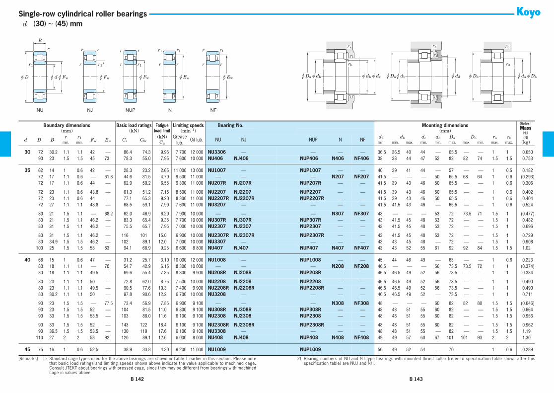
NFNNUPNJNU
r r
u Ew
r1r1
r r
u Ew
r1r
r r1
r
u Fw
rr r
u Fw
r1r
r
r1
B
u du D u Fw u Da u dbu db u dc
rb
u dbu Da u dd u da u Db
ra
u Db
rbrara
Single-row cylindrical roller bearings
30
72 30.2 1.1 1.1 42
⎯
86.4 74.3 9.95 7 700 12 000
NU3306
⎯
⎯ ⎯ ⎯
36.5 36.5 40 44
⎯
65.5
⎯ ⎯
1 1 0.650
30
90 23 1.5 1.5 45 73 78.3 55.0 7.95 7 600 10 000
NU406 NJ406
NUP406 N406 NF406
38 38 44 47 52 82 82 74 1.5 1.5 0.753
35
62 14 1 0.6 42
⎯
28.3 23.2 2.65 11 000 13 000
NU1007
⎯
NUP1007
⎯ ⎯
40 39 41 44
⎯
57
⎯ ⎯
1 0.5 0.182
35
72 17 1.1 0.6
⎯
61.8 44.6 31.5 4.70 9 500 11 000
⎯ ⎯
⎯
N207 NF207
41.5
⎯ ⎯ ⎯
50 65.5 68 64 1 0.6 (0.293)
35
72 17 1.1 0.6 44
⎯
62.9 50.2 6.55 9 300 11 000
NU207R NJ207R
NUP207R
⎯ ⎯
41.5 39 43 46 50 65.5
⎯ ⎯
1 0.6 0.306
35
72 23 1.1 0.6 43.8
⎯
61.3 51.2 7.15 8 500 11 000
NU2207 NJ2207 NUP2207 ⎯ ⎯ 41.5 39 43 46 50 65.5 ⎯ ⎯ 1 0.6 0.40235 72 23 1.1 0.6 44 ⎯ 77.1 65.3 9.20 8 300 11 000 NU2207R NJ2207R NUP2207R ⎯ ⎯ 41.5 39 43 46 50 65.5 ⎯ ⎯ 1 0.6 0.40435 72 27 1.1 1.1 43.8 ⎯ 68.5 59.1 7.90 7 600 11 000 NU3207 ⎯ ⎯ ⎯ ⎯ 41.5 41.5 43 46 ⎯ 65.5 ⎯ ⎯ 1 0.6 0.524
35 80 21 1.5 1.1 ⎯ 68.2 62.0 46.9 6.20 7 900 10 000 ⎯ ⎯ ⎯ N307 NF307 43 ⎯ ⎯ ⎯ 53 72 73.5 71 1.5 1 (0.477)35 80 21 1.5 1.1 46.2 ⎯ 83.3 65.4 9.35 7 700 10 000 NU307R NJ307R NUP307R ⎯ ⎯ 43 41.5 45 48 53 72 ⎯ ⎯ 1.5 1 0.48235 80 31 1.5 1.1 46.2 ⎯ 75.5 65.7 7.95 7 000 10 000 NU2307 NJ2307 NUP2307 ⎯ ⎯ 43 41.5 45 48 53 72 ⎯ ⎯ 1.5 1 0.696
35 80 31 1.5 1.1 46.2 ⎯ 116 101 15.0 6 900 10 000 NU2307R NJ2307R NUP2307R ⎯ ⎯ 43 41.5 45 48 53 72 ⎯ ⎯ 1.5 1 0.72935 80 34.9 1.5 1.5 46.2 ⎯ 102 89.1 12.0 7 000 10 000 NU3307 ⎯ ⎯ ⎯ ⎯ 43 43 45 48 ⎯ 72 ⎯ ⎯ 1.5 1 0.90835 100 25 1.5 1.5 53 83 94.1 68.9 9.25 6 600 8 800 NU407 NJ407 NUP407 N407 NF407 43 43 52 55 61 92 92 84 1.5 1.5 1.02
40 68 15 1 0.6 47 ⎯ 31.2 25.7 3.10 10 000 12 000 NU1008 ⎯ NUP1008 ⎯ ⎯ 45 44 46 49 ⎯ 63 ⎯ ⎯ 1 0.6 0.22340 80 18 1.1 1.1 ⎯ 70 54.7 42.9 6.15 8 300 10 000 ⎯ ⎯ ⎯ N208 NF208 46.5 ⎯ ⎯ ⎯ 56 73.5 73.5 72 1 1 (0.374)40 80 18 1.1 1.1 49.5 ⎯ 69.6 55.4 7.35 8 300 9 900 NU208R NJ208R NUP208R ⎯ ⎯ 46.5 46.5 49 52 56 73.5 ⎯ ⎯ 1 1 0.384
40 80 23 1.1 1.1 50 ⎯ 72.8 62.0 8.75 7 500 10 000 NU2208 NJ2208 NUP2208 ⎯ ⎯ 46.5 46.5 49 52 56 73.5 ⎯ ⎯ 1 1 0.49040 80 23 1.1 1.1 49.5 ⎯ 90.5 77.6 10.3 7 400 9 900 NU2208R NJ2208R NUP2208R ⎯ ⎯ 46.5 46.5 49 52 56 73.5 ⎯ ⎯ 1 1 0.49040 80 30.2 1.1 1.1 50 ⎯ 97.8 90.6 12.2 6 700 10 000 NU3208 ⎯ ⎯ ⎯ ⎯ 46.5 46.5 49 52 ⎯ 73.5 ⎯ ⎯ 1 1 0.711
40 90 23 1.5 1.5 ⎯ 77.5 73.4 56.9 7.85 6 900 9 100 ⎯ ⎯ ⎯ N308 NF308 48 ⎯ ⎯ ⎯ 60 82 82 80 1.5 1.5 (0.646)40 90 23 1.5 1.5 52 ⎯ 104 81.5 11.0 6 800 9 100 NU308R NJ308R NUP308R ⎯ ⎯ 48 48 51 55 60 82 ⎯ ⎯ 1.5 1.5 0.66440 90 33 1.5 1.5 53.5 ⎯ 103 88.0 11.6 6 100 9 100 NU2308 NJ2308 NUP2308 ⎯ ⎯ 48 48 51 55 60 82 ⎯ ⎯ 1.5 1.5 0.956
40 90 33 1.5 1.5 52 ⎯ 143 122 18.4 6 100 9 100 NU2308R NJ2308R NUP2308R ⎯ ⎯ 48 48 51 55 60 82 ⎯ ⎯ 1.5 1.5 0.96240 90 36.5 1.5 1.5 53.5 ⎯ 130 119 17.6 6 100 9 100 NU3308 ⎯ ⎯ ⎯ ⎯ 48 48 51 55 ⎯ 82 ⎯ ⎯ 1.5 1.5 1.1940 110 27 2 2 58 92 120 89.1 12.6 6 000 8 000 NU408 NJ408 NUP408 N408 NF408 49 49 57 60 67 101 101 93 2 2 1.30
45 75 16 1 0.6 52.5 ⎯ 38.9 33.8 4.30 9 200 11 000 NU1009 ⎯ NUP1009 ⎯ ⎯ 50 49 52 54 ⎯ 70 ⎯ ⎯ 1 0.6 0.289
Boundary dimensions Basic load ratings Fatigue Limiting speeds Bearing No. Mounting dimensions (Refer.)Mass
NU(N)
(kg)
(mm) (kN) load limit (min−1) (mm)
d D Br r1 Fw Ew Cr C0r
(kN) Greaselub.
Oil lub. NU NJ NUP N NFda db dc dd Da Db ra rb
min. min. Cu min. min. max. min. min. max. max. min. max. max.
[Remarks] 1) Standard cage types used for the above bearings are shown in Table 1 earlier in this section. Please notethat basic load ratings and limiting speeds shown above indicate the value applicable to machined cage.Consult JTEKT about bearings with pressed cage, since they may be different from bearings with machinedcage in values above.
2) Bearing numbers of NU and NJ type bearings with mounted thrust collar (refer to specification table shown after thisspecification table) are NUJ and NH.
B 142 B 143
d (30) ∼ (45) mm

NFNNUPNJNU
r r
u Ew
r1r1
r r
u Ew
r1r
r r1
r
u Fw
rr r
u Fw
r1r
r
r1
B
u du D u Fw u Da u dbu db u dc
rb
u dbu Da u dd u da u Db
ra
u Db
rbrara
Single-row cylindrical roller bearings
45 85 19 1.1 1.1 ⎯ 75 57.6 46.9 6.70 7 700 9 200 ⎯ ⎯ ⎯ N209 NF209 51.5 ⎯ ⎯ ⎯ 61 78.5 78.5 77 1 1 (0.427)45 85 19 1.1 1.1 54.5 ⎯ 78.9 66.4 9.05 7 600 9 200 NU209R NJ209R NUP209R ⎯ ⎯ 51.5 51.5 54 57 61 78.5 ⎯ ⎯ 1 1 0.43945 85 23 1.1 1.1 55 ⎯ 76.6 67.8 9.60 6 900 9 200 NU2209 NJ2209 NUP2209 ⎯ ⎯ 51.5 51.5 54 57 61 78.5 ⎯ ⎯ 1 1 0.536
45 85 23 1.1 1.1 54.5 ⎯ 95.1 84.6 11.2 6 900 9 200 NU2209R NJ2209R NUP2209R ⎯ ⎯ 51.5 51.5 54 57 61 78.5 ⎯ ⎯ 1 1 0.53645 85 30.2 1.1 1.1 55 ⎯ 103 99.0 13.3 6 100 9 200 NU3209 ⎯ ⎯ ⎯ ⎯ 51.5 51.5 54 57 ⎯ 78.5 ⎯ ⎯ 1 1 0.77045 100 25 1.5 1.5 ⎯ 86.5 98.5 77.5 11.3 6 200 8 300 ⎯ ⎯ ⎯ N309 NF309 53 ⎯ ⎯ ⎯ 66 92 92 89 1.5 1.5 (0.865)
45 100 25 1.5 1.5 58.5 ⎯ 122 98.3 13.5 6 100 8 200 NU309R NJ309R NUP309R ⎯ ⎯ 53 53 57 60 66 92 ⎯ ⎯ 1.5 1.5 0.90945 100 36 1.5 1.5 58.5 ⎯ 124 113 14.3 5 500 8 300 NU2309 NJ2309 NUP2309 ⎯ ⎯ 53 53 57 60 66 92 ⎯ ⎯ 1.5 1.5 1.2545 100 36 1.5 1.5 58.5 ⎯ 172 153 23.0 5 400 8 200 NU2309R NJ2309R NUP2309R ⎯ ⎯ 53 53 57 60 66 92 ⎯ ⎯ 1.5 1.5 1.32
45 100 39.7 1.5 1.5 58.5 ⎯ 164 149 22.6 5 500 8 300 NU3309 ⎯ ⎯ ⎯ ⎯ 53 53 57 60 ⎯ 92 ⎯ ⎯ 1.5 1.5 1.5945 120 29 2 2 64.5 100.5 134 112 13.8 5 400 7 200 NU409 NJ409 NUP409 N409 NF409 54 54 63 66 74 111 111 102 2 2 1.64
50 80 16 1 0.6 57.5 ⎯ 42.2 36.8 4.80 8 400 9 900 NU1010 ⎯ NUP1010 ⎯ ⎯ 55 54 57 59 ⎯ 75 ⎯ ⎯ 1 0.6 0.30650 90 20 1.1 1.1 ⎯ 80.4 60.3 51.0 7.30 7 100 8 500 ⎯ ⎯ ⎯ N210 NF210 56.5 ⎯ ⎯ ⎯ 67 83.5 83.5 82 1 1 (0.479)50 90 20 1.1 1.1 59.5 ⎯ 82.5 71.9 9.85 7 100 8 500 NU210R NJ210R NUP210R ⎯ ⎯ 56.5 56.5 58 62 67 83.5 ⎯ ⎯ 1 1 0.497
50 90 23 1.1 1.1 60.4 ⎯ 80.3 73.6 10.4 6 400 8 500 NU2210 NJ2210 NUP2210 ⎯ ⎯ 56.5 56.5 58 62 67 83.5 ⎯ ⎯ 1 1 0.58050 90 23 1.1 1.1 59.5 ⎯ 99.5 91.5 12.1 6 400 8 500 NU2210R NJ2210R NUP2210R ⎯ ⎯ 56.5 56.5 58 62 67 83.5 ⎯ ⎯ 1 1 0.58050 90 30.2 1.1 1.1 60.4 ⎯ 108 108 14.5 5 700 8 500 NU3210 ⎯ ⎯ ⎯ ⎯ 56.5 56.5 58 62 ⎯ 83.5 ⎯ ⎯ 1 1 0.829
50 110 27 2 2 ⎯ 95 109 93.4 11.7 5 600 7 500 ⎯ ⎯ ⎯ N310 NF310 59 ⎯ ⎯ ⎯ 73 101 101 98 2 2 (1.15)50 110 27 2 2 65 ⎯ 138 113 16.0 5 500 7 400 NU310R NJ310R NUP310R ⎯ ⎯ 59 59 63 67 73 101 ⎯ ⎯ 2 2 1.1550 110 40 2 2 65 ⎯ 151 142 20.1 5 000 7 500 NU2310 NJ2310 NUP2310 ⎯ ⎯ 59 59 63 67 73 101 ⎯ ⎯ 2 2 1.69
50 110 40 2 2 65 ⎯ 203 187 28.6 4 900 7 400 NU2310R NJ2310R NUP2310R ⎯ ⎯ 59 59 63 67 73 101 ⎯ ⎯ 2 2 1.7650 110 44.4 2 2 65 ⎯ 195 183 27.3 5 000 7 500 NU3310 ⎯ ⎯ ⎯ ⎯ 59 59 63 67 ⎯ 101 ⎯ ⎯ 2 2 2.1450 130 31 2.1 2.1 70.8 110.8 161 136 17.4 4 900 6 600 NU410 NJ410 NUP410 N410 NF410 61 61 69 73 81 119 119 112 2 2 2.01
55 90 18 1.1 1 64.5 ⎯ 47.1 43.8 5.75 7 600 8 900 NU1011 ⎯ NUP1011 ⎯ ⎯ 61.5 60 63 66 ⎯ 83.5 ⎯ ⎯ 1 1 0.44555 100 21 1.5 1.1 ⎯ 88.5 72.5 62.3 8.30 6 400 7 700 ⎯ ⎯ ⎯ N211 NF211 63 ⎯ ⎯ ⎯ 73 92 93.5 91 1.5 1 (0.633)55 100 21 1.5 1.1 66 ⎯ 108 98.7 14.2 6 400 7 700 NU211R NJ211R NUP211R ⎯ ⎯ 63 61.5 65 68 73 92 ⎯ ⎯ 1.5 1 0.650
55 100 25 1.5 1.1 66.5 ⎯ 94.2 87.2 11.6 5 800 7 700 NU2211 NJ2211 NUP2211 ⎯ ⎯ 63 61.5 65 68 73 92 ⎯ ⎯ 1.5 1 0.780
Boundary dimensions Basic load ratings Fatigue Limiting speeds Bearing No. Mounting dimensions (Refer.)Mass
NU(N)
(kg)
(mm) (kN) load limit (min−1) (mm)
d D Br r1 Fw Ew Cr C0r
(kN) Greaselub.
Oil lub. NU NJ NUP N NFda db dc dd Da Db ra rb
min. min. Cu min. min. max. min. min. max. max. min. max. max.
[Remarks] 1) Standard cage types used for the above bearings are shown in Table 1 earlier in this section. Please notethat basic load ratings and limiting speeds shown above indicate the value applicable to machined cage.Consult JTEKT about bearings with pressed cage, since they may be different from bearings with machinedcage in values above.
2) Bearing numbers of NU and NJ type bearings with mounted thrust collar (refer to specification table shown after thisspecification table) are NUJ and NH.
B 144 B 145
d (45) ∼ (55) mm

NFNNUPNJNU
r r
u Ew
r1r1
r r
u Ew
r1r
r r1
r
u Fw
rr r
u Fw
r1r
r
r1
B
u du D u Fw u Da u dbu db u dc
rb
u dbu Da u dd u da u Db
ra
u Db
rbrara
Single-row cylindrical roller bearings
55 100 25 1.5 1.1 66 ⎯ 127 122 16.9 5 800 7 700 NU2211R NJ2211R NUP2211R ⎯ ⎯ 63 61.5 65 68 73 92 ⎯ ⎯ 1.5 1 0.80655 100 33.3 1.5 1.5 66.5 ⎯ 119 118 16.1 5 100 7 700 NU3211 ⎯ ⎯ ⎯ ⎯ 63 63 65 68 ⎯ 92 ⎯ ⎯ 1.5 1 1.1455 120 29 2 2 ⎯ 104.5 138 111 15.8 5 100 6 800 ⎯ ⎯ ⎯ N311 NF311 64 ⎯ ⎯ ⎯ 80 111 111 107 2 2 (1.44)
55 120 29 2 2 70.5 ⎯ 172 143 19.8 5 100 6 700 NU311R NJ311R NUP311R ⎯ ⎯ 64 64 69 72 80 111 ⎯ ⎯ 2 2 1.5055 120 43 2 2 70.5 ⎯ 185 162 24.6 4 500 6 800 NU2311 NJ2311 NUP2311 ⎯ ⎯ 64 64 69 72 80 111 ⎯ ⎯ 2 2 2.1055 120 43 2 2 70.5 ⎯ 251 233 35.3 4 500 6 700 NU2311R NJ2311R NUP2311R ⎯ ⎯ 64 64 69 72 80 111 ⎯ ⎯ 2 2 2.25
55 120 49.2 2 2 70.5 ⎯ 235 220 32.8 4 500 6 800 NU3311 ⎯ ⎯ ⎯ ⎯ 64 64 69 72 ⎯ 111 ⎯ ⎯ 2 2 2.8155 140 33 2.1 2.1 77.2 117.2 174 138 19.6 4 600 6 100 NU411 NJ411 NUP411 N411 NF411 66 66 76 79 87 129 129 119 2 2 2.51
60 95 18 1.1 1 69.5 ⎯ 53.0 50.0 6.75 7 000 8 300 NU1012 ⎯ NUP1012 ⎯ ⎯ 66.5 65 68 71 ⎯ 88.5 ⎯ ⎯ 1 1 0.47760 110 22 1.5 1.5 ⎯ 97.5 85.7 79.9 10.4 5 800 7 000 ⎯ ⎯ ⎯ N212 NF212 68 ⎯ ⎯ ⎯ 80 102 102 100 1.5 1.5 (0.823)60 110 22 1.5 1.5 72 ⎯ 122 107 15.7 5 800 6 900 NU212R NJ212R NUP212R ⎯ ⎯ 68 68 71 75 80 102 ⎯ ⎯ 1.5 1.5 0.830
60 110 28 1.5 1.5 73.5 ⎯ 120 123 15.3 5 200 7 000 NU2212 NJ2212 NUP2212 ⎯ ⎯ 68 68 71 75 80 102 ⎯ ⎯ 1.5 1.5 1.0760 110 28 1.5 1.5 72 ⎯ 164 157 21.7 5 200 6 900 NU2212R NJ2212R NUP2212R ⎯ ⎯ 68 68 71 75 80 102 ⎯ ⎯ 1.5 1.5 1.0960 110 36.5 1.5 1.5 73.5 ⎯ 160 167 24.7 4 700 7 000 NU3212 ⎯ ⎯ ⎯ ⎯ 68 68 71 75 ⎯ 102 ⎯ ⎯ 1.5 1.5 1.52
60 130 31 2.1 2.1 ⎯ 113 155 126 17.3 4 700 6 300 ⎯ ⎯ ⎯ N312 NF312 71 ⎯ ⎯ ⎯ 86 119 119 116 2 2 (1.83)60 130 31 2.1 2.1 77 ⎯ 187 157 22.1 4 600 6 200 NU312R NJ312R NUP312R ⎯ ⎯ 71 71 75 79 86 119 ⎯ ⎯ 2 2 1.8760 130 46 2.1 2.1 77 ⎯ 211 188 29.4 4 200 6 300 NU2312 NJ2312 NUP2312 ⎯ ⎯ 71 71 75 79 86 119 ⎯ ⎯ 2 2 2.69
60 130 46 2.1 2.1 77 ⎯ 278 262 39.6 4 100 6 200 NU2312R NJ2312R NUP2312R ⎯ ⎯ 71 71 75 79 86 119 ⎯ ⎯ 2 2 2.8160 130 54 2.1 2.1 77 ⎯ 275 265 39.9 4 200 6 300 NU3312 ⎯ ⎯ ⎯ ⎯ 71 71 75 79 ⎯ 119 ⎯ ⎯ 2 2 3.6160 150 35 2.1 2.1 83 127 209 184 26.1 4 200 5 700 NU412 NJ412 NUP412 N412 NF412 71 71 82 85 94 139 139 128 2 2 3.02
65 100 18 1.1 1 74.5 ⎯ 54.4 52.9 7.15 6 600 7 800 NU1013 ⎯ NUP1013 ⎯ ⎯ 71.5 70 73 76 ⎯ 93.5 ⎯ ⎯ 1 1 0.50665 120 23 1.5 1.5 ⎯ 105.6 105 94.4 13.5 5 400 6 400 ⎯ ⎯ ⎯ N213 NF213 73 ⎯ ⎯ ⎯ 87 112 112 108 1.5 1.5 (1.05)65 120 23 1.5 1.5 78.5 ⎯ 134 119 16.1 5 300 6 400 NU213R NJ213R NUP213R ⎯ ⎯ 73 73 77 81 87 112 ⎯ ⎯ 1.5 1.5 1.05
65 120 31 1.5 1.5 79.6 ⎯ 150 149 20.6 4 800 6 400 NU2213 NJ2213 NUP2213 ⎯ ⎯ 73 73 77 81 87 112 ⎯ ⎯ 1.5 1.5 1.4365 120 31 1.5 1.5 78.5 ⎯ 186 181 27.7 4 800 6 400 NU2213R NJ2213R NUP2213R ⎯ ⎯ 73 73 77 81 87 112 ⎯ ⎯ 1.5 1.5 1.4565 120 38.1 1.5 1.5 79.6 ⎯ 186 197 29.7 4 300 6 400 NU3213 ⎯ ⎯ ⎯ ⎯ 73 73 77 81 ⎯ 112 ⎯ ⎯ 1.5 1.5 1.90
65 140 33 2.1 2.1 ⎯ 121.5 169 139 19.2 4 300 5 800 ⎯ ⎯ ⎯ N313 NF313 76 ⎯ ⎯ ⎯ 93 129 129 125 2 2 (2.19)
Boundary dimensions Basic load ratings Fatigue Limiting speeds Bearing No. Mounting dimensions (Refer.)Mass
NU(N)
(kg)
(mm) (kN) load limit (min−1) (mm)
d D Br r1 Fw Ew Cr C0r
(kN) Greaselub.
Oil lub. NU NJ NUP N NFda db dc dd Da Db ra rb
min. min. Cu min. min. max. min. min. max. max. min. max. max.
[Remarks] 1) Standard cage types used for the above bearings are shown in Table 1 earlier in this section. Please notethat basic load ratings and limiting speeds shown above indicate the value applicable to machined cage.Consult JTEKT about bearings with pressed cage, since they may be different from bearings with machinedcage in values above.
2) Bearing numbers of NU and NJ type bearings with mounted thrust collar (refer to specification table shown after thisspecification table) are NUJ and NH.
B 146 B 147
d (55) ∼ (65) mm

NFNNUPNJNU
r r
u Ew
r1r1
r r
u Ew
r1r
r r1
r
u Fw
rr r
u Fw
r1r
r
r1
B
u du D u Fw u Da u dbu db u dc
rb
u dbu Da u dd u da u Db
ra
u Db
rbrara
Single-row cylindrical roller bearings
65 140 33 2.1 2.1 82.5 ⎯ 226 191 29.8 4 300 5 700 NU313R NJ313R NUP313R ⎯ ⎯ 76 76 81 85 93 129 ⎯ ⎯ 2 2 2.3165 140 48 2.1 2.1 83.5 ⎯ 235 212 32.9 3 900 5 800 NU2313 NJ2313 NUP2313 ⎯ ⎯ 76 76 81 85 93 129 ⎯ ⎯ 2 2 3.2565 140 48 2.1 2.1 82.5 ⎯ 310 287 43.3 3 800 5 700 NU2313R NJ2313R NUP2313R ⎯ ⎯ 76 76 81 85 93 129 ⎯ ⎯ 2 2 3.36
65 140 58.7 2.1 2.1 83.5 ⎯ 302 294 43.9 3 900 5 800 NU3313 ⎯ ⎯ ⎯ ⎯ 76 76 81 85 ⎯ 129 ⎯ ⎯ 2 2 4.5365 160 37 2.1 2.1 89.3 135.3 228 203 28.2 4 000 5 300 NU413 NJ413 NUP413 N413 NF413 76 76 88 91 100 149 149 137 2 2 3.58
70 110 20 1.1 1 80 ⎯ 72.9 70.4 10.1 6 100 7 200 NU1014 ⎯ NUP1014 ⎯ ⎯ 76.5 75 78 82 ⎯ 103.5 ⎯ ⎯ 1 1 0.70270 125 24 1.5 1.5 ⎯ 110.5 104 95.2 13.6 5 100 6 100 ⎯ ⎯ ⎯ N214 NF214 78 ⎯ ⎯ ⎯ 92 117 117 114 1.5 1.5 (1.15)70 125 24 1.5 1.5 83.5 ⎯ 148 137 19.0 5 000 6 000 NU214R NJ214R NUP214R ⎯ ⎯ 78 78 82 86 92 117 ⎯ ⎯ 1.5 1.5 1.16
70 125 31 1.5 1.5 84.5 ⎯ 149 151 20.8 4 600 6 100 NU2214 NJ2214 NUP2214 ⎯ ⎯ 78 78 82 86 92 117 ⎯ ⎯ 1.5 1.5 1.5270 125 31 1.5 1.5 83.5 ⎯ 194 194 29.8 4 500 6 000 NU2214R NJ2214R NUP2214R ⎯ ⎯ 78 78 82 86 92 117 ⎯ ⎯ 1.5 1.5 1.5370 125 39.7 1.5 1.5 84.5 ⎯ 185 198 30.0 4 100 6 100 NU3214 ⎯ ⎯ ⎯ ⎯ 78 78 82 86 ⎯ 117 ⎯ ⎯ 1.5 1.5 2.09
70 150 35 2.1 2.1 ⎯ 130 198 168 23.3 4 000 5 400 ⎯ ⎯ ⎯ N314 NF314 81 ⎯ ⎯ ⎯ 100 139 139 134 2 2 (2.73)70 150 35 2.1 2.1 89 ⎯ 256 222 33.4 4 000 5 300 NU314R NJ314R NUP314R ⎯ ⎯ 81 81 87 92 100 139 ⎯ ⎯ 2 2 2.8170 150 51 2.1 2.1 90 ⎯ 279 262 39.3 3 600 5 400 NU2314 NJ2314 NUP2314 ⎯ ⎯ 81 81 87 92 100 139 ⎯ ⎯ 2 2 3.97
70 150 51 2.1 2.1 89 ⎯ 342 323 47.1 3 600 5 300 NU2314R NJ2314R NUP2314R ⎯ ⎯ 81 81 87 92 100 139 ⎯ ⎯ 2 2 4.0870 150 63.5 2.1 2.1 90 ⎯ 354 356 51.5 3 600 5 400 NU3314 ⎯ ⎯ ⎯ ⎯ 81 81 87 92 ⎯ 139 ⎯ ⎯ 2 2 5.6270 180 42 3 3 100 152 285 257 35.2 3 500 4 700 NU414 NJ414 NUP414 N414 NF414 83 83 99 102 112 167 167 153 2.5 2.5 5.26
75 115 20 1.1 1 85 ⎯ 80.0 78.1 10.2 5 700 6 800 NU1015 ⎯ NUP1015 ⎯ ⎯ 81.5 80 83 87 ⎯ 108.5 ⎯ ⎯ 1 1 0.73575 130 25 1.5 1.5 ⎯ 116.5 121 118 16.1 4 800 5 800 ⎯ ⎯ ⎯ N215 NF215 83 ⎯ ⎯ ⎯ 96 122 122 120 1.5 1.5 (1.24)75 130 25 1.5 1.5 88.5 ⎯ 163 156 21.9 4 800 5 700 NU215R NJ215R NUP215R ⎯ ⎯ 83 83 87 90 96 122 ⎯ ⎯ 1.5 1.5 1.29
75 130 31 1.5 1.5 88.5 ⎯ 162 172 22.3 4 300 5 800 NU2215 NJ2215 NUP2215 ⎯ ⎯ 83 83 87 90 96 122 ⎯ ⎯ 1.5 1.5 1.5775 130 31 1.5 1.5 88.5 ⎯ 202 207 31.5 4 300 5 700 NU2215R NJ2215R NUP2215R ⎯ ⎯ 83 83 87 90 96 122 ⎯ ⎯ 1.5 1.5 1.6175 130 41.3 1.5 1.5 88.5 ⎯ 210 226 34.1 3 900 5 800 NU3215 ⎯ ⎯ ⎯ ⎯ 83 83 87 90 ⎯ 122 ⎯ ⎯ 1.5 1.5 2.28
75 160 37 2.1 2.1 ⎯ 139.5 224 205 28.4 3 800 5 000 ⎯ ⎯ ⎯ N315 NF315 86 ⎯ ⎯ ⎯ 106 149 149 143 2 2 (3.19)75 160 37 2.1 2.1 95 ⎯ 300 263 39.9 3 700 5 000 NU315R NJ315R NUP315R ⎯ ⎯ 86 86 93 97 106 149 ⎯ ⎯ 2 2 3.3775 160 55 2.1 2.1 95.5 ⎯ 323 327 43.4 3 400 5 000 NU2315 NJ2315 NUP2315 ⎯ ⎯ 86 86 93 97 106 149 ⎯ ⎯ 2 2 4.84
75 160 55 2.1 2.1 95 ⎯ 412 395 57.3 3 300 5 000 NU2315R NJ2315R NUP2315R ⎯ ⎯ 86 86 93 97 106 149 ⎯ ⎯ 2 2 5.00
Boundary dimensions Basic load ratings Fatigue Limiting speeds Bearing No. Mounting dimensions (Refer.)Mass
NU(N)
(kg)
(mm) (kN) load limit (min−1) (mm)
d D Br r1 Fw Ew Cr C0r
(kN) Greaselub.
Oil lub. NU NJ NUP N NFda db dc dd Da Db ra rb
min. min. Cu min. min. max. min. min. max. max. min. max. max.
[Remarks] 1) Standard cage types used for the above bearings are shown in Table 1 earlier in this section. Please notethat basic load ratings and limiting speeds shown above indicate the value applicable to machined cage.Consult JTEKT about bearings with pressed cage, since they may be different from bearings with machinedcage in values above.
2) Bearing numbers of NU and NJ type bearings with mounted thrust collar (refer to specification table shown after thisspecification table) are NUJ and NH.
B 148 B 149
d (65) ∼ (75) mm

NFNNUPNJNU
r r
u Ew
r1r1
r r
u Ew
r1r
r r1
r
u Fw
rr r
u Fw
r1r
r
r1
B
u du D u Fw u Da u dbu db u dc
rb
u dbu Da u dd u da u Db
ra
u Db
rbrara
Single-row cylindrical roller bearings
75 160 68.3 2.1 2.1 95.5 ⎯ 423 430 62.1 3 400 5 000 NU3315 ⎯ ⎯ ⎯ ⎯ 86 86 93 97 ⎯ 149 ⎯ ⎯ 2 2 6.8675 190 45 3 3 104.5 160.5 328 274 40.2 3 300 4 400 NU415 NJ415 NUP415 N415 NF415 88 88 103 107 118 177 177 162 2.5 2.5 6.25
80 125 22 1.1 1 91.5 ⎯ 87.2 86.4 11.5 5 300 6 300 NU1016 ⎯ NUP1016 ⎯ ⎯ 86.5 85 90 94 ⎯ 118.5 ⎯ ⎯ 1 1 0.99480 140 26 2 2 ⎯ 125.3 133 122 16.2 4 500 5 400 ⎯ ⎯ ⎯ N216 NF216 89 ⎯ ⎯ ⎯ 104 131 131 128 2 2 (1.51)80 140 26 2 2 95.3 ⎯ 174 167 23.0 4 400 5 300 NU216R NJ216R NUP216R ⎯ ⎯ 89 89 94 97 104 131 ⎯ ⎯ 2 2 1.56
80 140 33 2 2 95.3 ⎯ 184 186 27.8 4 000 5 400 NU2216 NJ2216 NUP2216 ⎯ ⎯ 89 89 94 97 104 131 ⎯ ⎯ 2 2 1.9680 140 33 2 2 95.3 ⎯ 233 243 35.8 4 000 5 300 NU2216R NJ2216R NUP2216R ⎯ ⎯ 89 89 94 97 104 131 ⎯ ⎯ 2 2 2.0380 140 44.4 2 2 95.3 ⎯ 238 259 37.8 3 600 5 400 NU3216 ⎯ ⎯ ⎯ ⎯ 89 89 94 97 ⎯ 131 ⎯ ⎯ 2 2 2.87
80 170 39 2.1 2.1 ⎯ 147 238 207 30.7 3 500 4 700 ⎯ ⎯ ⎯ N316 NF316 91 ⎯ ⎯ ⎯ 114 159 159 151 2 2 (3.83)80 170 39 2.1 2.1 101 ⎯ 320 282 42.1 3 500 4 700 NU316R NJ316R NUP316R ⎯ ⎯ 91 91 99 105 114 159 ⎯ ⎯ 2 2 4.0080 170 58 2.1 2.1 103 ⎯ 343 332 46.9 3 100 4 700 NU2316 NJ2316 NUP2316 ⎯ ⎯ 91 91 99 105 114 159 ⎯ ⎯ 2 2 5.83
80 170 58 2.1 2.1 101 ⎯ 445 431 61.1 3 100 4 700 NU2316R NJ2316R NUP2316R ⎯ ⎯ 91 91 99 105 114 159 ⎯ ⎯ 2 2 5.9580 170 68.3 2.1 2.1 103 ⎯ 423 436 61.9 3 100 4 700 NU3316 ⎯ ⎯ ⎯ ⎯ 91 91 99 105 ⎯ 159 ⎯ ⎯ 2 2 7.7280 200 48 3 3 110 170 374 315 45.2 3 100 4 200 NU416 NJ416 NUP416 N416 NF416 93 93 109 112 124 187 187 172 2.5 2.5 7.28
85 130 22 1.1 1 96.5 ⎯ 89.8 91.2 12.0 5 100 6 000 NU1017 ⎯ NUP1017 ⎯ ⎯ 91.5 90 95 99 ⎯ 123.5 ⎯ ⎯ 1 1 1.0485 150 28 2 2 ⎯ 133.8 151 140 18.7 4 200 5 000 ⎯ ⎯ ⎯ N217 NF217 94 ⎯ ⎯ ⎯ 110 141 141 137 2 2 (1.90)85 150 28 2 2 100.5 ⎯ 209 199 26.3 4 200 5 000 NU217R NJ217R NUP217R ⎯ ⎯ 94 94 99 104 110 141 ⎯ ⎯ 2 2 1.94
85 150 36 2 2 101.8 ⎯ 212 218 31.6 3 800 5 000 NU2217 NJ2217 NUP2217 ⎯ ⎯ 94 94 99 104 110 141 ⎯ ⎯ 2 2 2.5085 150 36 2 2 100.5 ⎯ 272 279 41.6 3 700 5 000 NU2217R NJ2217R NUP2217R ⎯ ⎯ 94 94 99 104 110 141 ⎯ ⎯ 2 2 2.5385 150 49.2 2 2 101.8 ⎯ 269 296 42.1 3 300 5 000 NU3217 ⎯ ⎯ ⎯ ⎯ 94 94 99 104 ⎯ 141 ⎯ ⎯ 2 2 3.67
85 180 41 3 3 ⎯ 156 281 247 35.6 3 300 4 500 ⎯ ⎯ ⎯ N317 NF317 98 ⎯ ⎯ ⎯ 119 167 167 160 2.5 2.5 (4.52)85 180 41 3 3 108 ⎯ 364 330 48.3 3 300 4 400 NU317R NJ317R NUP317R ⎯ ⎯ 98 98 106 110 119 167 ⎯ ⎯ 2.5 2.5 4.8085 180 60 3 3 108 ⎯ 394 382 54.2 3 000 4 500 NU2317 NJ2317 NUP2317 ⎯ ⎯ 98 98 106 110 119 167 ⎯ ⎯ 2.5 2.5 6.62
85 180 60 3 3 108 ⎯ 491 485 67.7 2 900 4 400 NU2317R NJ2317R NUP2317R ⎯ ⎯ 98 98 106 110 119 167 ⎯ ⎯ 2.5 2.5 6.9885 180 73 3 3 108 ⎯ 499 517 71.5 3 000 4 500 NU3317 ⎯ ⎯ ⎯ ⎯ 98 98 106 110 ⎯ 167 ⎯ ⎯ 2.5 2.5 9.2385 210 52 4 4 113 177 416 350 49.7 3 000 4 000 NU417 NJ417 NUP417 N417 NF417 101 101 111 115 128 194 194 179 3 3 8.68
90 140 24 1.5 1.1 103 ⎯ 106 109 14.6 4 700 5 600 NU1018 ⎯ NUP1018 ⎯ ⎯ 98 96.5 101 106 ⎯ 132 ⎯ ⎯ 1.5 1 1.34
Boundary dimensions Basic load ratings Fatigue Limiting speeds Bearing No. Mounting dimensions (Refer.)Mass
NU(N)
(kg)
(mm) (kN) load limit (min−1) (mm)
d D Br r1 Fw Ew Cr C0r
(kN) Greaselub.
Oil lub. NU NJ NUP N NFda db dc dd Da Db ra rb
min. min. Cu min. min. max. min. min. max. max. min. max. max.
[Remarks] 1) Standard cage types used for the above bearings are shown in Table 1 earlier in this section. Please notethat basic load ratings and limiting speeds shown above indicate the value applicable to machined cage.Consult JTEKT about bearings with pressed cage, since they may be different from bearings with machinedcage in values above.
2) Bearing numbers of NU and NJ type bearings with mounted thrust collar (refer to specification table shown after thisspecification table) are NUJ and NH.
B 150 B 151
d (75) ∼ (90) mm

NFNNUPNJNU
r r
u Ew
r1r1
r r
u Ew
r1r
r r1
r
u Fw
rr r
u Fw
r1r
r
r1
B
u du D u Fw u Da u dbu db u dc
rb
u dbu Da u dd u da u Db
ra
u Db
rbrara
Single-row cylindrical roller bearings
90 160 30 2 2 ⎯ 143 190 178 22.9 3 900 4 700 ⎯ ⎯ ⎯ N218 NF218 99 ⎯ ⎯ ⎯ 116 151 151 146 2 2 (2.32)90 160 30 2 2 107 ⎯ 227 217 28.7 3 900 4 700 NU218R NJ218R NUP218R ⎯ ⎯ 99 99 105 109 116 151 ⎯ ⎯ 2 2 2.3890 160 40 2 2 107 ⎯ 259 265 38.9 3 500 4 700 NU2218 NJ2218 NUP2218 ⎯ ⎯ 99 99 105 109 116 151 ⎯ ⎯ 2 2 3.10
90 160 40 2 2 107 ⎯ 302 314 45.8 3 500 4 700 NU2218R NJ2218R NUP2218R ⎯ ⎯ 99 99 105 109 116 151 ⎯ ⎯ 2 2 3.2190 160 52.4 2 2 107 ⎯ 338 373 52.8 3 100 4 700 NU3218 ⎯ ⎯ ⎯ ⎯ 99 99 105 109 ⎯ 151 ⎯ ⎯ 2 2 4.4990 190 43 3 3 ⎯ 165 300 265 38.7 3 100 4 200 ⎯ ⎯ ⎯ N318 NF318 103 ⎯ ⎯ ⎯ 127 177 177 169 2.5 2.5 (5.27)
90 190 43 3 3 113.5 ⎯ 395 355 50.6 3 100 4 100 NU318R NJ318R NUP318R ⎯ ⎯ 103 103 111 117 127 177 ⎯ ⎯ 2.5 2.5 5.4790 190 64 3 3 115 ⎯ 408 395 55.5 2 800 4 200 NU2318 NJ2318 NUP2318 ⎯ ⎯ 103 103 111 117 127 177 ⎯ ⎯ 2.5 2.5 7.9090 190 64 3 3 113.5 ⎯ 544 534 74.5 2 800 4 100 NU2318R NJ2318R NUP2318R ⎯ ⎯ 103 103 111 117 127 177 ⎯ ⎯ 2.5 2.5 8.12
90 190 73 3 3 115 ⎯ 535 559 75.6 2 800 4 200 NU3318 ⎯ ⎯ ⎯ ⎯ 103 103 111 117 ⎯ 177 ⎯ ⎯ 2.5 2.5 10.390 225 54 4 4 123.5 191.5 468 400 55.1 2 800 3 700 NU418 NJ418 NUP418 N418 NF418 106 106 122 125 139 209 209 194 3 3 10.3
95 145 24 1.5 1.1 108 ⎯ 110 115 15.2 4 500 5 300 NU1019 ⎯ NUP1019 ⎯ ⎯ 103 101.5 106 111 ⎯ 137 ⎯ ⎯ 1.5 1 1.4095 170 32 2.1 2.1 ⎯ 151.5 207 195 25.1 3 700 4 400 ⎯ ⎯ ⎯ N219 NF219 106 ⎯ ⎯ ⎯ 123 159 159 155 2 2 (2.80)95 170 32 2.1 2.1 112.5 ⎯ 275 265 38.3 3 700 4 400 NU219R NJ219R NUP219R ⎯ ⎯ 106 106 111 116 123 159 ⎯ ⎯ 2 2 2.92
95 170 43 2.1 2.1 113.5 ⎯ 288 298 42.9 3 300 4 400 NU2219 NJ2219 NUP2219 ⎯ ⎯ 106 106 111 116 123 159 ⎯ ⎯ 2 2 3.8595 170 43 2.1 2.1 112.5 ⎯ 358 371 52.8 3 300 4 400 NU2219R NJ2219R NUP2219R ⎯ ⎯ 106 106 111 116 123 159 ⎯ ⎯ 2 2 3.9395 170 55.6 2.1 2.1 113.5 ⎯ 371 412 57.2 3 000 4 400 NU3219 ⎯ ⎯ ⎯ ⎯ 106 106 111 116 ⎯ 159 ⎯ ⎯ 2 2 5.42
95 200 45 3 3 ⎯ 173.5 323 311 41.3 3 000 4 000 ⎯ ⎯ ⎯ N319 NF319 108 ⎯ ⎯ ⎯ 134 187 187 178 2.5 2.5 (6.10)95 200 45 3 3 121.5 ⎯ 418 387 54.3 2 900 3 900 NU319R NJ319R NUP319R ⎯ ⎯ 108 108 119 124 134 187 ⎯ ⎯ 2.5 2.5 6.4295 200 67 3 3 121.5 ⎯ 465 496 62.6 2 600 4 000 NU2319 NJ2319 NUP2319 ⎯ ⎯ 108 108 119 124 134 187 ⎯ ⎯ 2.5 2.5 9.39
95 200 77.8 3 3 121.5 ⎯ 609 654 86.8 2 600 4 000 NU3319 ⎯ ⎯ ⎯ ⎯ 108 108 119 124 ⎯ 187 ⎯ ⎯ 2.5 2.5 12.195 240 55 4 4 133.5 201.5 502 444 60.1 2 600 3 400 NU419 NJ419 NUP419 N419 NF419 111 111 132 136 149 224 224 204 3 3 13.6
100 150 24 1.5 1.1 113 ⎯ 114 120 15.8 4 300 5 100 NU1020 ⎯ NUP1020 ⎯ ⎯ 108 106.5 111 116 ⎯ 142 ⎯ ⎯ 1.5 1 1.46100 180 34 2.1 2.1 ⎯ 160 229 217 28.1 3 500 4 200 ⎯ ⎯ ⎯ N220 NF220 111 ⎯ ⎯ ⎯ 130 169 169 164 2 2 (3.38)100 180 34 2.1 2.1 119 ⎯ 312 306 43.0 3 500 4 200 NU220R NJ220R NUP220R ⎯ ⎯ 111 111 117 122 130 169 ⎯ ⎯ 2 2 3.52
100 180 46 2.1 2.1 120 ⎯ 322 338 47.3 3 100 4 200 NU2220 NJ2220 NUP2220 ⎯ ⎯ 111 111 117 122 130 169 ⎯ ⎯ 2 2 4.67100 180 46 2.1 2.1 119 ⎯ 417 444 60.7 3 100 4 200 NU2220R NJ2220R NUP2220R ⎯ ⎯ 111 111 117 122 130 169 ⎯ ⎯ 2 2 4.82
Boundary dimensions Basic load ratings Fatigue Limiting speeds Bearing No. Mounting dimensions (Refer.)Mass
NU(N)
(kg)
(mm) (kN) load limit (min−1) (mm)
d D Br r1 Fw Ew Cr C0r
(kN) Greaselub.
Oil lub. NU NJ NUP N NFda db dc dd Da Db ra rb
min. min. Cu min. min. max. min. min. max. max. min. max. max.
[Remarks] 1) Standard cage types used for the above bearings are shown in Table 1 earlier in this section. Please notethat basic load ratings and limiting speeds shown above indicate the value applicable to machined cage.Consult JTEKT about bearings with pressed cage, since they may be different from bearings with machinedcage in values above.
2) Bearing numbers of NU and NJ type bearings with mounted thrust collar (refer to specification table shown after thisspecification table) are NUJ and NH.
B 152 B 153
d (90) ∼ (100) mm

NFNNUPNJNU
r r
u Ew
r1r1
r r
u Ew
r1r
r r1
r
u Fw
rr r
u Fw
r1r
r
r1
B
u du D u Fw u Da u dbu db u dc
rb
u dbu Da u dd u da u Db
ra
u Db
rbrara
Single-row cylindrical roller bearings
100 180 60.3 2.1 2.1 120 ⎯ 409 459 61.9 2 800 4 200 NU3220 ⎯ ⎯ ⎯ ⎯ 111 111 117 122 ⎯ 169 ⎯ ⎯ 2 2 6.62100 215 47 3 3 ⎯ 185.5 373 337 47.2 2 800 3 700 ⎯ ⎯ ⎯ N320 NF320 113 ⎯ ⎯ ⎯ 143 202 202 190 2.5 2.5 (7.59)100 215 47 3 3 127.5 ⎯ 474 424 58.7 2 700 3 600 NU320R NJ320R NUP320R ⎯ ⎯ 113 113 125 132 143 202 ⎯ ⎯ 2.5 2.5 7.75
100 215 73 3 3 129.5 ⎯ 513 548 68.4 2 500 3 700 NU2320 NJ2320 NUP2320 ⎯ ⎯ 113 113 125 132 143 202 ⎯ ⎯ 2.5 2.5 11.9100 215 73 3 3 127.5 ⎯ 713 717 94.7 2 400 3 600 NU2320R NJ2320R NUP2320R ⎯ ⎯ 113 113 125 132 143 202 ⎯ ⎯ 2.5 2.5 12.1100 215 82.6 3 3 129.5 ⎯ 663 706 93.2 2 500 3 700 NU3320 ⎯ ⎯ ⎯ ⎯ 113 113 125 132 ⎯ 202 ⎯ ⎯ 2.5 2.5 15.0
100 250 58 4 4 139 211 560 498 67.3 2 500 3 300 NU420 NJ420 NUP420 N420 NF420 116 116 137 141 156 234 234 213 3 3 14.0
105 160 26 2 1.1 119.5 ⎯ 136 149 19.6 4 100 4 800 NU1021 ⎯ NUP1021 ⎯ ⎯ 114 111.5 118 122 ⎯ 151 ⎯ ⎯ 2 1 1.85105 190 36 2.1 2.1 ⎯ 168.8 251 241 34.1 3 300 3 900 ⎯ ⎯ ⎯ N221 NF221 116 ⎯ ⎯ ⎯ 137 179 179 173 2 2 (4.44)105 190 65.1 2.1 2.1 126.8 ⎯ 431 482 64.3 2 600 3 900 NU3221 ⎯ ⎯ ⎯ ⎯ 116 116 124 129 ⎯ 179 ⎯ ⎯ 2 2 8.00
105 225 49 3 3 ⎯ 195 426 417 53.1 2 600 3 500 ⎯ ⎯ ⎯ N321 NF321 118 ⎯ ⎯ ⎯ 149 212 212 199 2.5 2.5 (8.68)105 225 77 3 3 135 ⎯ 711 750 97.3 2 300 3 500 NU2321 ⎯ NUP2321 ⎯ ⎯ 118 118 131 138 ⎯ 212 ⎯ ⎯ 2.5 2.5 15.6105 225 87.3 3 3 135 ⎯ 799 871 113 2 300 3 500 NU3321 ⎯ ⎯ ⎯ ⎯ 118 118 132 137 ⎯ 212 ⎯ ⎯ 2.5 2.5 17.4
105 260 60 4 4 144.5 220.5 581 510 67.6 2 400 3 100 NU421 NJ421 NUP421 N421 NF421 121 121 143 147 162 244 244 223 3 3 19.1
110 170 28 2 1.1 125 ⎯ 168 171 21.7 3 800 4 500 NU1022 ⎯ NUP1022 ⎯ ⎯ 119 116.5 124 128 ⎯ 161 ⎯ ⎯ 2 1 2.31110 200 38 2.1 2.1 ⎯ 178.5 300 290 40.1 3 100 3 700 ⎯ ⎯ ⎯ N222 NF222 121 ⎯ ⎯ ⎯ 144 189 189 182 2 2 (5.24)110 200 38 2.1 2.1 132.5 ⎯ 366 365 51.1 3 100 3 700 NU222R NJ222R NUP222R ⎯ ⎯ 121 121 130 135 144 189 ⎯ ⎯ 2 2 4.90
110 200 53 2.1 2.1 132.5 ⎯ 397 442 55.1 2 800 3 700 NU2222 NJ2222 NUP2222 ⎯ ⎯ 121 121 130 135 144 189 ⎯ ⎯ 2 2 6.93110 200 53 2.1 2.1 132.5 ⎯ 479 517 69.9 2 800 3 700 NU2222R NJ2222R NUP2222R ⎯ ⎯ 121 121 130 135 144 189 ⎯ ⎯ 2 2 6.93110 200 69.8 2.1 2.1 132.5 ⎯ 533 607 80.6 2 500 3 700 NU3222 ⎯ ⎯ ⎯ ⎯ 121 121 130 135 ⎯ 189 ⎯ ⎯ 2 2 9.55
110 240 50 3 3 ⎯ 207 475 467 58.4 2 500 3 300 ⎯ ⎯ ⎯ N322 NF322 123 ⎯ ⎯ ⎯ 158 227 227 211 2.5 2.5 (10.4)110 240 50 3 3 143 ⎯ 564 525 70.0 2 400 3 200 NU322R NJ322R NUP322R ⎯ ⎯ 123 123 140 145 158 227 ⎯ ⎯ 2.5 2.5 10.7110 240 80 3 3 143 ⎯ 755 789 102 2 200 3 300 NU2322 NJ2322 NUP2322 ⎯ ⎯ 123 123 140 145 158 227 ⎯ ⎯ 2.5 2.5 18.8
110 240 80 3 3 143 ⎯ 843 880 112 2 200 3 200 NU2322R NJ2322R NUP2322R ⎯ ⎯ 123 123 140 145 158 227 ⎯ ⎯ 2.5 2.5 18.8110 240 92.1 3 3 143 ⎯ 849 918 118 2 200 3 300 NU3322 ⎯ ⎯ ⎯ ⎯ 123 123 140 145 ⎯ 227 ⎯ ⎯ 2.5 2.5 21.1110 280 65 4 4 155 235 685 621 80.8 2 200 2 900 NU422 NJ422 NUP422 N422 NF422 126 126 153 157 173 264 264 237 3 3 19.9
120 180 28 2 1.1 135 ⎯ 173 181 22.6 3 500 4 200 NU1024 ⎯ NUP1024 ⎯ ⎯ 129 126.5 134 138 ⎯ 171 ⎯ ⎯ 2 1 2.47
Boundary dimensions Basic load ratings Fatigue Limiting speeds Bearing No. Mounting dimensions (Refer.)Mass
NU(N)
(kg)
(mm) (kN) load limit (min−1) (mm)
d D Br r1 Fw Ew Cr C0r
(kN) Greaselub.
Oil lub. NU NJ NUP N NFda db dc dd Da Db ra rb
min. min. Cu min. min. max. min. min. max. max. min. max. max.
[Remarks] 1) Standard cage types used for the above bearings are shown in Table 1 earlier in this section. Please notethat basic load ratings and limiting speeds shown above indicate the value applicable to machined cage.Consult JTEKT about bearings with pressed cage, since they may be different from bearings with machinedcage in values above.
2) Bearing numbers of NU and NJ type bearings with mounted thrust collar (refer to specification table shown after thisspecification table) are NUJ and NH.
B 154 B 155
d (100) ∼ (120) mm

NFNNUPNJNU
r r
u Ew
r1r1
r r
u Ew
r1r
r r1
r
u Fw
rr r
u Fw
r1r
r
r1
B
u du D u Fw u Da u dbu db u dc
rb
u dbu Da u dd u da u Db
ra
u Db
rbrara
Single-row cylindrical roller bearings
120 215 40 2.1 2.1 ⎯ 191.5 325 318 42.9 2 900 3 400 ⎯ ⎯ ⎯ N224 NF224 131 ⎯ ⎯ ⎯ 156 204 204 196 2 2 (6.31)120 215 40 2.1 2.1 143.5 ⎯ 419 421 57.6 2 800 3 400 NU224R NJ224R NUP224R ⎯ ⎯ 131 131 141 146 156 204 ⎯ ⎯ 2 2 5.85120 215 58 2.1 2.1 143.5 ⎯ 434 492 61.2 2 600 3 400 NU2224 NJ2224 NUP2224 ⎯ ⎯ 131 131 141 146 156 204 ⎯ ⎯ 2 2 8.56
120 215 58 2.1 2.1 143.5 ⎯ 565 619 80.9 2 600 3 400 NU2224R NJ2224R NUP2224R ⎯ ⎯ 131 131 141 146 156 204 ⎯ ⎯ 2 2 8.56120 215 76 2.1 2.1 143.5 ⎯ 596 695 89.2 2 300 3 400 NU3224 ⎯ ⎯ ⎯ ⎯ 131 131 141 146 ⎯ 204 ⎯ ⎯ 2 2 11.9120 260 55 3 3 ⎯ 226 561 551 67.1 2 200 3 000 ⎯ ⎯ ⎯ N324 NF324 133 ⎯ ⎯ ⎯ 171 247 247 230 2.5 2.5 (13.1)
120 260 55 3 3 154 ⎯ 660 610 79.8 2 200 3 000 NU324R NJ324R NUP324R ⎯ ⎯ 133 133 151 156 171 247 ⎯ ⎯ 2.5 2.5 13.4120 260 86 3 3 154 ⎯ 886 918 116 2 000 3 000 NU2324 NJ2324 NUP2324 ⎯ ⎯ 133 133 151 156 171 247 ⎯ ⎯ 2.5 2.5 23.1120 260 86 3 3 154 ⎯ 991 1 030 129 2 000 3 000 NU2324R NJ2324R NUP2324R ⎯ ⎯ 133 133 151 156 172 247 ⎯ ⎯ 2.5 2.5 23.1
120 260 106 3 3 154 ⎯ 1 030 1 120 139 2 000 3 000 NU3324 ⎯ ⎯ ⎯ ⎯ 133 133 151 156 ⎯ 247 ⎯ ⎯ 2.5 2.5 28.3120 310 72 5 5 170 260 841 770 98.7 1 900 2 600 NU424 NJ424 NUP424 N424 NF424 140 140 168 172 190 290 290 262 4 4 28.0
130 200 33 2 1.1 148 ⎯ 215 238 29.5 3 200 3 800 NU1026 ⎯ NUP1026 ⎯ ⎯ 139 136.5 146 151 ⎯ 191 ⎯ ⎯ 2 1 3.77130 230 40 3 3 ⎯ 204 338 362 45.2 2 700 3 200 ⎯ ⎯ ⎯ N226 NF226 143 ⎯ ⎯ ⎯ 168 217 217 208 2.5 2.5 (7.21)130 230 40 3 3 153.5 ⎯ 454 453 61.0 2 600 3 200 NU226R NJ226R NUP226R ⎯ ⎯ 143 143 151 158 168 217 ⎯ ⎯ 2.5 2.5 6.60
130 230 64 3 3 156 ⎯ 474 560 68.7 2 400 3 200 NU2226 NJ2226 NUP2226 ⎯ ⎯ 143 143 151 158 168 217 ⎯ ⎯ 2.5 2.5 11.2130 230 64 3 3 153.5 ⎯ 662 737 95.8 2 400 3 200 NU2226R NJ2226R NUP2226R ⎯ ⎯ 143 143 151 158 168 217 ⎯ ⎯ 2.5 2.5 11.2130 230 80 3 3 156 ⎯ 689 857 107 2 100 3 200 NU3226 ⎯ ⎯ ⎯ ⎯ 143 143 151 158 ⎯ 217 ⎯ ⎯ 2.5 2.5 14.1
130 280 58 4 4 ⎯ 243 699 667 85.7 2 100 2 700 ⎯ ⎯ ⎯ N326 NF326 146 ⎯ ⎯ ⎯ 184 264 264 247 3 3 (16.4)130 280 58 4 4 167 ⎯ 771 736 94.1 2 000 2 700 NU326R NJ326R NUP326R ⎯ ⎯ 146 146 164 169 184 264 ⎯ ⎯ 3 3 16.7130 280 93 4 4 167 ⎯ 1 050 1 130 138 1 800 2 700 NU2326 NJ2326 NUP2326 ⎯ ⎯ 146 146 164 169 184 264 ⎯ ⎯ 3 3 29.1
130 280 93 4 4 167 ⎯ 1 150 1 230 150 1 800 2 700 NU2326R NJ2326R NUP2326R ⎯ ⎯ 146 146 164 169 186 264 ⎯ ⎯ 3 3 29.1130 280 112 4 4 167 ⎯ 1 170 1 290 158 1 800 2 700 NU3326 ⎯ ⎯ ⎯ ⎯ 146 146 164 169 ⎯ 264 ⎯ ⎯ 3 3 34.6130 340 78 5 5 185 285 964 876 108 1 800 2 300 NU426 NJ426 NUP426 N426 NF426 150 150 183 187 208 320 320 287 4 4 36.1
140 210 33 2 1.1 158 ⎯ 220 250 30.5 3 000 3 600 NU1028 ⎯ NUP1028 ⎯ ⎯ 149 146.5 156 161 ⎯ 201 ⎯ ⎯ 2 1 4.00140 250 42 3 3 ⎯ 221 406 421 55.5 2 400 2 900 ⎯ ⎯ ⎯ N228 NF228 153 ⎯ ⎯ ⎯ 182 237 237 228 2.5 2.5 (8.78)140 250 42 3 3 169 ⎯ 491 514 67.5 2 400 2 900 NU228R NJ228R NUP228R ⎯ ⎯ 153 153 166 171 182 237 ⎯ ⎯ 2.5 2.5 8.50
140 250 68 3 3 169 ⎯ 583 671 84.3 2 200 2 900 NU2228 NJ2228 NUP2228 ⎯ ⎯ 153 153 166 171 182 237 ⎯ ⎯ 2.5 2.5 14.3140 250 68 3 3 169 ⎯ 716 835 106 2 200 2 900 NU2228R NJ2228R NUP2228R ⎯ ⎯ 153 153 166 171 182 237 ⎯ ⎯ 2.5 2.5 14.3
Boundary dimensions Basic load ratings Fatigue Limiting speeds Bearing No. Mounting dimensions (Refer.)Mass
NU(N)
(kg)
(mm) (kN) load limit (min−1) (mm)
d D Br r1 Fw Ew Cr C0r
(kN) Greaselub.
Oil lub. NU NJ NUP N NFda db dc dd Da Db ra rb
min. min. Cu min. min. max. min. min. max. max. min. max. max.
[Remarks] 1) Standard cage types used for the above bearings are shown in Table 1 earlier in this section. Please notethat basic load ratings and limiting speeds shown above indicate the value applicable to machined cage.Consult JTEKT about bearings with pressed cage, since they may be different from bearings with machinedcage in values above.
2) Bearing numbers of NU and NJ type bearings with mounted thrust collar (refer to specification table shown after thisspecification table) are NUJ and NH.
B 156 B 157
d (120) ∼ (140) mm

NFNNUPNJNU
r r
u Ew
r1r1
r r
u Ew
r1r
r r1
r
u Fw
rr r
u Fw
r1r
r
r1
B
u du D u Fw u Da u dbu db u dc
rb
u dbu Da u dd u da u Db
ra
u Db
rbrara
Single-row cylindrical roller bearings
140 250 88 3 3 169 ⎯ 757 939 114 1 900 2 900 NU3228 ⎯ ⎯ ⎯ ⎯ 153 153 166 171 ⎯ 237 ⎯ ⎯ 2.5 2.5 18.5140 300 62 4 4 ⎯ 260 771 746 93.8 1 900 2 500 ⎯ ⎯ ⎯ N328 NF328 156 ⎯ ⎯ ⎯ 198 284 284 264 3 3 (21.8)140 300 62 4 4 180 ⎯ 829 797 99.4 1 900 2 500 NU328R NJ328R NUP328R ⎯ ⎯ 156 156 176 182 198 284 ⎯ ⎯ 3 3 21.8
140 300 102 4 4 180 ⎯ 1 150 1 250 150 1 700 2 500 NU2328 NJ2328 NUP2328 ⎯ ⎯ 156 156 176 182 198 284 ⎯ ⎯ 3 3 36.8140 300 102 4 4 180 ⎯ 1 270 1 380 167 1 700 2 500 NU2328R NJ2328R NUP2328R ⎯ ⎯ 156 156 176 182 200 284 ⎯ ⎯ 3 3 36.8140 300 118 4 4 180 ⎯ 1 360 1 550 185 1 700 2 500 NU3328 ⎯ ⎯ ⎯ ⎯ 156 156 176 182 ⎯ 284 ⎯ ⎯ 3 3 41.5
140 360 82 5 5 198 302 1 090 1 020 124 1 600 2 200 NU428 NJ428 NUP428 N428 NF428 160 160 195 200 222 340 340 304 4 4 46.8
150 225 35 2.1 1.5 169.5 ⎯ 252 281 32.8 2 800 3 300 NU1030 ⎯ NUP1030 ⎯ ⎯ 161 158 167 173 ⎯ 214 ⎯ ⎯ 2 1.5 4.83150 270 45 3 3 ⎯ 238 468 492 63.4 2 200 2 700 ⎯ ⎯ ⎯ N230 NF230 163 ⎯ ⎯ ⎯ 196 257 257 245 2.5 2.5 (11.1)150 270 45 3 3 182 ⎯ 560 594 75.8 2 200 2 600 NU230R NJ230R NUP230R ⎯ ⎯ 163 163 179 184 196 257 ⎯ ⎯ 2.5 2.5 10.7
150 270 73 3 3 182 ⎯ 683 800 99.7 2 000 2 700 NU2230 NJ2230 NUP2230 ⎯ ⎯ 163 163 179 184 196 257 ⎯ ⎯ 2.5 2.5 18.7150 270 73 3 3 182 ⎯ 828 982 120 2 000 2 600 NU2230R NJ2230R NUP2230R ⎯ ⎯ 163 163 179 184 196 257 ⎯ ⎯ 2.5 2.5 18.7150 270 96 3 3 182 ⎯ 939 1 200 143 1 800 2 700 NU3230 ⎯ ⎯ ⎯ ⎯ 163 163 179 184 ⎯ 257 ⎯ ⎯ 2.5 2.5 23.7
150 320 65 4 4 ⎯ 277 829 807 99.1 1 800 2 300 ⎯ ⎯ ⎯ N330 NF330 166 ⎯ ⎯ ⎯ 213 304 304 281 3 3 (25.6)150 320 65 4 4 193 ⎯ 948 922 115 1 700 2 300 NU330R NJ330R NUP330R ⎯ ⎯ 166 166 190 195 213 304 ⎯ ⎯ 3 3 27.0150 320 108 4 4 193 ⎯ 1 270 1 400 167 1 600 2 300 NU2330 NJ2330 NUP2330 ⎯ ⎯ 166 166 190 195 213 304 ⎯ ⎯ 3 3 44.7
150 320 108 4 4 193 ⎯ 1 450 1 600 187 1 500 2 300 NU2330R NJ2330R NUP2330R ⎯ ⎯ 166 166 190 195 213 304 ⎯ ⎯ 3 3 44.7150 320 128 4 4 193 ⎯ 1 610 1 890 217 1 600 2 300 NU3330 ⎯ ⎯ ⎯ ⎯ 166 166 190 195 ⎯ 304 ⎯ ⎯ 3 3 51.4150 380 85 5 5 213 317 1 160 1 120 134 1 500 2 000 NU430 NJ430 NUP430 N430 NF430 170 170 210 216 237 360 360 319 4 4 53.3
160 240 38 2.1 1.5 180 ⎯ 297 330 42.8 2 600 3 000 NU1032 ⎯ NUP1032 ⎯ ⎯ 171 168 178 184 ⎯ 229 ⎯ ⎯ 2 1.5 5.93160 290 48 3 3 ⎯ 255 535 568 71.3 2 100 2 500 ⎯ ⎯ ⎯ N232 NF232 173 ⎯ ⎯ ⎯ 210 277 277 262 2.5 2.5 (13.9)160 290 48 3 3 195 ⎯ 624 666 83.3 2 000 2 400 NU232R NJ232R NUP232R ⎯ ⎯ 173 173 192 197 210 277 ⎯ ⎯ 2.5 2.5 14.8
160 290 80 3 3 195 ⎯ 790 939 113 1 800 2 500 NU2232 NJ2232 NUP2232 ⎯ ⎯ 173 173 192 197 210 277 ⎯ ⎯ 2.5 2.5 23.6160 290 80 3 3 193 ⎯ 1 010 1 190 141 1 800 2 400 NU2232R NJ2232R NUP2232R ⎯ ⎯ 173 173 192 197 210 277 ⎯ ⎯ 2.5 2.5 23.6160 290 104 3 3 195 ⎯ 1 070 1 390 163 1 600 2 500 NU3232 ⎯ ⎯ ⎯ ⎯ 173 173 192 197 ⎯ 277 ⎯ ⎯ 2.5 2.5 29.8
160 340 68 4 4 ⎯ 292 872 876 106 1 600 2 200 ⎯ ⎯ ⎯ N332 NF332 176 ⎯ ⎯ ⎯ 228 324 324 296 3 3 (30.2)160 340 68 4 4 204 ⎯ 1 070 1 050 128 1 600 2 100 NU332R NJ332R NUP332R ⎯ ⎯ 176 176 200 211 228 324 ⎯ ⎯ 3 3 32.0
Boundary dimensions Basic load ratings Fatigue Limiting speeds Bearing No. Mounting dimensions (Refer.)Mass
NU(N)
(kg)
(mm) (kN) load limit (min−1) (mm)
d D Br r1 Fw Ew Cr C0r
(kN) Greaselub.
Oil lub. NU NJ NUP N NFda db dc dd Da Db ra rb
min. min. Cu min. min. max. min. min. max. max. min. max. max.
[Remarks] 1) Standard cage types used for the above bearings are shown in Table 1 earlier in this section. Please notethat basic load ratings and limiting speeds shown above indicate the value applicable to machined cage.Consult JTEKT about bearings with pressed cage, since they may be different from bearings with machinedcage in values above.
2) Bearing numbers of NU and NJ type bearings with mounted thrust collar (refer to specification table shown after thisspecification table) are NUJ and NH.
B 158 B 159
d (140) ∼ (160) mm

NFNNUPNJNU
r r
u Ew
r1r1
r r
u Ew
r1r
r r1
r
u Fw
rr r
u Fw
r1r
r
r1
B
u du D u Fw u Da u dbu db u dc
rb
u dbu Da u dd u da u Db
ra
u Db
rbrara
Single-row cylindrical roller bearings
160 340 114 4 4 208 ⎯ 1 340 1 520 178 1 400 2 200 NU2332 NJ2332 NUP2332 ⎯ ⎯ 176 176 200 211 228 324 ⎯ ⎯ 3 3 53.1160 340 114 4 4 204 ⎯ 1 640 1 820 212 1 400 2 100 NU2332R NJ2332R NUP2332R ⎯ ⎯ 176 176 200 211 228 324 ⎯ ⎯ 3 3 53.1160 340 136 4 4 208 ⎯ 1 590 1 890 216 1 400 2 200 NU3332 ⎯ ⎯ ⎯ ⎯ 176 176 200 211 ⎯ 324 ⎯ ⎯ 3 3 61.5
170 260 42 2.1 2.1 193 ⎯ 347 400 50.5 2 400 2 800 NU1034 ⎯ NUP1034 ⎯ ⎯ 181 181 190 197 ⎯ 249 ⎯ ⎯ 2 2 7.90170 310 52 4 4 ⎯ 272 596 637 78.4 1 900 2 300 ⎯ ⎯ ⎯ N234 NF234 186 ⎯ ⎯ ⎯ 223 294 294 280 3 3 (17.2)170 310 52 4 4 207 ⎯ 754 802 98.7 1 900 2 200 NU234R NJ234R NUP234R ⎯ ⎯ 186 186 204 211 223 294 ⎯ ⎯ 3 3 18.6
170 310 86 4 4 208 ⎯ 896 1 080 127 1 700 2 300 NU2234 NJ2234 NUP2234 ⎯ ⎯ 186 186 204 211 223 294 ⎯ ⎯ 3 3 29.2170 310 86 4 4 205 ⎯ 1 210 1 410 166 1 700 2 200 NU2234R NJ2234R NUP2234R ⎯ ⎯ 186 186 204 211 223 294 ⎯ ⎯ 3 3 29.2170 310 110 4 4 208 ⎯ 1 210 1 580 181 1 500 2 300 NU3234 ⎯ ⎯ ⎯ ⎯ 186 186 204 211 ⎯ 294 ⎯ ⎯ 3 3 36.2
170 360 72 4 4 220 310 997 1 010 122 1 500 2 000 NU334 NJ334 NUP334 N334 NF334 186 186 216 223 241 344 344 314 3 3 38.6170 360 120 4 4 220 ⎯ 1 530 1 750 199 1 300 2 000 NU2334 NJ2334 NUP2334 ⎯ ⎯ 186 186 216 223 241 344 ⎯ ⎯ 3 3 62.6170 360 140 4 4 220 ⎯ 1 770 2 120 240 1 300 2 000 NU3334 ⎯ ⎯ ⎯ ⎯ 186 186 216 223 ⎯ 344 ⎯ ⎯ 3 3 70.8
180 280 46 2.1 2.1 205 ⎯ 447 503 63.2 2 200 2 600 NU1036 ⎯ NUP1036 ⎯ ⎯ 191 191 203 209 ⎯ 269 ⎯ ⎯ 2 2 10.5180 320 52 4 4 ⎯ 282 618 677 82.2 1 800 2 200 ⎯ ⎯ ⎯ N236 NF236 196 ⎯ ⎯ ⎯ 233 304 304 290 3 3 (18.0)180 320 52 4 4 217 ⎯ 783 852 104 1 800 2 100 NU236R NJ236R NUP236R ⎯ ⎯ 196 196 214 221 233 304 ⎯ ⎯ 3 3 19.3
180 320 86 4 4 218 ⎯ 929 1 140 133 1 600 2 200 NU2236 NJ2236 NUP2236 ⎯ ⎯ 196 196 214 221 233 304 ⎯ ⎯ 3 3 30.4180 320 86 4 4 215 ⎯ 1 260 1 510 175 1 600 2 100 NU2236R NJ2236R NUP2236R ⎯ ⎯ 196 196 214 221 233 304 ⎯ ⎯ 3 3 30.4180 320 112 4 4 218 ⎯ 1 250 1 680 190 1 400 2 200 NU3236 ⎯ ⎯ ⎯ ⎯ 196 196 214 221 ⎯ 304 ⎯ ⎯ 3 3 38.4
180 380 75 4 4 232 328 1 130 1 150 136 1 400 1 900 NU336 NJ336 NUP336 N336 NF336 196 196 227 235 255 364 364 332 3 3 42.6180 380 126 4 4 232 ⎯ 1 690 1 940 220 1 300 1 900 NU2336 NJ2336 NUP2336 ⎯ ⎯ 196 196 227 235 255 364 ⎯ ⎯ 3 3 73.0180 380 150 4 4 232 ⎯ 2 070 2 520 276 1 300 1 900 NU3336 ⎯ ⎯ ⎯ ⎯ 196 196 227 235 ⎯ 364 ⎯ ⎯ 3 3 84.4
190 290 46 2.1 2.1 215 ⎯ 460 530 65.7 2 100 2 500 NU1038 ⎯ NUP1038 ⎯ ⎯ 201 201 213 219 ⎯ 279 ⎯ ⎯ 2 2 10.9190 340 55 4 4 ⎯ 299 694 768 91.3 1 700 2 000 ⎯ ⎯ ⎯ N238 NF238 206 ⎯ ⎯ ⎯ 247 324 324 310 3 3 (21.5)190 340 55 4 4 230 ⎯ 869 954 114 1 700 2 000 NU238R NJ238R NUP238R ⎯ ⎯ 206 206 227 234 247 324 ⎯ ⎯ 3 3 23.3
190 340 92 4 4 231 ⎯ 1 040 1 290 146 1 500 2 000 NU2238 NJ2238 NUP2238 ⎯ ⎯ 206 206 227 234 247 324 ⎯ ⎯ 3 3 37.0190 340 92 4 4 228 ⎯ 1 380 1 670 189 1 500 2 000 NU2238R NJ2238R NUP2238R ⎯ ⎯ 206 206 227 234 247 324 ⎯ ⎯ 3 3 37.0190 340 120 4 4 231 ⎯ 1 420 1 930 226 1 300 2 000 NU3238 ⎯ ⎯ ⎯ ⎯ 206 206 227 234 ⎯ 324 ⎯ ⎯ 3 3 46.8
Boundary dimensions Basic load ratings Fatigue Limiting speeds Bearing No. Mounting dimensions (Refer.)Mass
NU(N)
(kg)
(mm) (kN) load limit (min−1) (mm)
d D Br r1 Fw Ew Cr C0r
(kN) Greaselub.
Oil lub. NU NJ NUP N NFda db dc dd Da Db ra rb
min. min. Cu min. min. max. min. min. max. max. min. max. max.
[Remarks] 1) Standard cage types used for the above bearings are shown in Table 1 earlier in this section. Please notethat basic load ratings and limiting speeds shown above indicate the value applicable to machined cage.Consult JTEKT about bearings with pressed cage, since they may be different from bearings with machinedcage in values above.
2) Bearing numbers of NU and NJ type bearings with mounted thrust collar (refer to specification table shown after thisspecification table) are NUJ and NH.
B 160 B 161
d (160) ∼ (190) mm

NFNNUPNJNU
r r
u Ew
r1r1
r r
u Ew
r1r
r r1
r
u Fw
rr r
u Fw
r1r
r
r1
B
u du D u Fw u Da u dbu db u dc
rb
u dbu Da u dd u da u Db
ra
u Db
rbrara
Single-row cylindrical roller bearings
190 400 78 5 5 245 345 1 220 1 260 146 1 300 1 800 NU338 NJ338 NUP338 N338 NF338 210 210 240 248 268 380 380 349 4 4 49.9190 400 132 5 5 245 ⎯ 1 900 2 220 245 1 200 1 800 NU2338 NJ2338 NUP2338 ⎯ ⎯ 210 210 240 248 268 380 ⎯ ⎯ 4 4 84.7190 400 155 5 5 245 ⎯ 2 340 2 910 316 1 200 1 800 NU3338 ⎯ ⎯ ⎯ ⎯ 210 210 240 248 ⎯ 380 ⎯ ⎯ 4 4 96.5
200 310 51 2.1 2.1 229 ⎯ 487 582 71.0 1 900 2 300 NU1040 ⎯ NUP1040 ⎯ ⎯ 211 211 226 233 ⎯ 299 ⎯ ⎯ 2 2 14.1200 360 58 4 4 ⎯ 316 775 865 102 1 600 1 900 ⎯ ⎯ ⎯ N240 NF240 216 ⎯ ⎯ ⎯ 261 344 344 328 3 3 (25.7)200 360 58 4 4 243 ⎯ 958 1 060 124 1 600 1 900 NU240R NJ240R NUP240R ⎯ ⎯ 216 216 240 247 261 344 ⎯ ⎯ 3 3 27.2
200 360 98 4 4 244 ⎯ 1 190 1 490 169 1 400 1 900 NU2240 NJ2240 NUP2240 ⎯ ⎯ 216 216 240 247 261 344 ⎯ ⎯ 3 3 44.4200 360 98 4 4 241 ⎯ 1 530 1 870 211 1 400 1 900 NU2240R NJ2240R NUP2240R ⎯ ⎯ 216 216 240 247 261 344 ⎯ ⎯ 3 3 44.4200 360 128 4 4 244 ⎯ 1 500 2 020 223 1 300 1 900 NU3240 ⎯ ⎯ ⎯ ⎯ 216 216 240 247 ⎯ 344 ⎯ ⎯ 3 3 56.2
200 420 80 5 5 260 360 1 220 1 270 145 1 200 1 700 NU340 NJ340 NUP340 N340 NF340 220 220 254 263 283 400 400 364 4 4 56.2200 420 138 5 5 260 ⎯ 1 890 2 240 244 1 100 1 700 NU2340 NJ2340 NUP2340 ⎯ ⎯ 220 220 254 263 283 400 ⎯ ⎯ 4 4 97.4200 420 165 5 5 260 ⎯ 2 330 2 930 314 1 100 1 700 NU3340 ⎯ ⎯ ⎯ ⎯ 220 220 250 258 ⎯ 400 ⎯ ⎯ 4 4 113
220 340 56 3 3 250 ⎯ 637 748 88.1 1 700 2 000 NU1044 ⎯ NUP1044 ⎯ ⎯ 233 233 248 254 ⎯ 327 ⎯ ⎯ 2.5 2.5 18.5220 400 65 4 4 270 350 949 1 080 123 1 400 1 700 NU244 NJ244 NUP244 N244 NF244 236 236 266 273 289 384 384 362 3 3 38.5220 400 108 4 4 270 ⎯ 1 420 1 810 196 1 200 1 700 NU2244 NJ2244 ⎯ ⎯ ⎯ 236 236 266 273 289 384 ⎯ ⎯ 3 3 60.9
220 400 144 4 4 270 ⎯ 2 040 2 880 319 1 100 1 700 NU3244 ⎯ ⎯ ⎯ ⎯ 236 236 266 273 ⎯ 384 ⎯ ⎯ 3 3 78.8220 460 88 5 5 284 396 1 490 1 570 176 1 100 1 500 NU344 NJ344 NUP344 N344 NF344 240 240 279 287 309 440 440 400 4 4 74.4220 460 145 5 5 284 ⎯ 2 260 2 690 287 990 1 500 NU2344 ⎯ NUP2344 ⎯ ⎯ 240 240 276 287 ⎯ 440 ⎯ ⎯ 4 4 119
220 460 180 5 5 284 ⎯ 2 660 3 300 347 990 1 500 NU3344 ⎯ ⎯ ⎯ ⎯ 240 240 279 287 ⎯ 440 ⎯ ⎯ 4 4 148
240 360 56 3 3 270 ⎯ 673 822 95.0 1 600 1 900 NU1048 ⎯ NUP1048 ⎯ ⎯ 253 253 268 275 ⎯ 347 ⎯ ⎯ 2.5 2.5 20.1240 440 72 4 4 295 385 1 170 1 340 150 1 200 1 500 NU248 NJ248 NUP248 N248 NF248 256 256 293 298 316 424 424 397 3 3 52.1240 440 120 4 4 295 ⎯ 1 790 2 320 246 1 100 1 500 NU2248 NJ2248 ⎯ ⎯ ⎯ 256 256 293 298 316 424 ⎯ ⎯ 3 3 82.5
240 440 160 4 4 295 ⎯ 2 450 3 460 358 990 1 500 NU3248 ⎯ ⎯ ⎯ ⎯ 256 256 293 298 ⎯ 424 ⎯ ⎯ 3 3 107240 500 95 5 5 310 430 1 790 1 950 211 990 1 300 NU348 NJ348 NUP348 N348 NF348 260 260 305 313 337 480 480 434 4 4 94.6240 500 155 5 5 310 ⎯ 2 710 3 320 346 880 1 300 NU2348 ⎯ NUP2348 ⎯ ⎯ 260 260 303 313 ⎯ 480 ⎯ ⎯ 4 4 152
240 500 195 5 5 310 ⎯ 3 170 4 070 414 880 1 300 NU3348 ⎯ ⎯ ⎯ ⎯ 260 260 305 313 ⎯ 480 ⎯ ⎯ 4 4 189
Boundary dimensions Basic load ratings Fatigue Limiting speeds Bearing No. Mounting dimensions (Refer.)Mass
NU(N)
(kg)
(mm) (kN) load limit (min−1) (mm)
d D Br r1 Fw Ew Cr C0r
(kN) Greaselub.
Oil lub. NU NJ NUP N NFda db dc dd Da Db ra rb
min. min. Cu min. min. max. min. min. max. max. min. max. max.
[Remarks] 1) Standard cage types used for the above bearings are shown in Table 1 earlier in this section. Please notethat basic load ratings and limiting speeds shown above indicate the value applicable to machined cage.Consult JTEKT about bearings with pressed cage, since they may be different from bearings with machinedcage in values above.
2) Bearing numbers of NU and NJ type bearings with mounted thrust collar (refer to specification table shown after thisspecification table) are NUJ and NH.
B 162 B 163
d (190) ∼ 240 mm

NFNNUPNJNU
r r
u Ew
r1r1
r r
u Ew
r1r
r r1
r
u Fw
rr r
u Fw
r1r
r
r1
B
u du D u Fw u Da u dbu db u dc
rb
u dbu Da u dd u da u Db
ra
u Db
rbrara
Single-row cylindrical roller bearings
260 400 65 4 4 296 ⎯ 819 979 110 1 400 1 700 NU1052 ⎯ NUP1052 ⎯ ⎯ 276 276 292 300 ⎯ 384 ⎯ ⎯ 3 3 29.2260 480 80 5 5 320 420 1 380 1 580 171 1 100 1 300 NU252 NJ252 NUP252 N252 NF252 280 280 318 323 343 460 460 432 4 4 69.0260 480 130 5 5 320 ⎯ 2 240 2 950 305 990 1 300 NU2252 NJ2252 ⎯ ⎯ ⎯ 280 280 318 323 343 460 ⎯ ⎯ 4 4 107
260 480 174 5 5 320 ⎯ 2 680 3 680 373 880 1 300 NU3252 ⎯ ⎯ ⎯ ⎯ 280 280 318 323 ⎯ 460 ⎯ ⎯ 4 4 139260 540 165 6 6 336 ⎯ 3 030 3 750 385 790 1 200 NU2352 ⎯ NUP2352 ⎯ ⎯ 284 284 327 339 ⎯ 516 ⎯ ⎯ 5 5 185260 540 206 6 6 336 ⎯ 3 670 4 790 473 790 1 200 NU3352 ⎯ ⎯ ⎯ ⎯ 284 284 330 339 ⎯ 516 ⎯ ⎯ 5 5 232
280 420 65 4 4 316 ⎯ 841 1 030 114 1 300 1 500 NU1056 ⎯ NUP1056 ⎯ ⎯ 296 296 313 320 ⎯ 404 ⎯ ⎯ 3 3 35.2280 500 80 5 5 340 440 1 430 1 680 179 1 000 1 200 NU256 NJ256 NUP256 N256 NF256 300 300 336 343 365 480 480 452 4 4 72.7
300 460 74 4 4 340 ⎯ 1 120 1 380 147 1 200 1 400 NU1060 ⎯ NUP1060 ⎯ ⎯ 316 316 337 344 ⎯ 444 ⎯ ⎯ 3 3 44.1300 540 85 5 5 364 476 1 690 1 960 206 920 1 100 NU260 NJ260 NUP260 N260 NF260 320 320 361 368 392 520 520 487 4 4 90.7
320 480 74 4 4 360 ⎯ 1 150 1 450 152 1 100 1 300 NU1064 ⎯ NUP1064 ⎯ ⎯ 336 336 356 365 ⎯ 464 ⎯ ⎯ 3 3 48.4320 580 92 5 5 390 510 1 920 2 270 232 840 1 000 NU264 NJ264 NUP264 N264 NF264 340 340 386 393 419 560 560 522 4 4 114320 670 112 7.5 7.5 425 ⎯ 2 460 2 880 287 650 870 NU364 ⎯ ⎯ ⎯ ⎯ 352 352 419 428 ⎯ 638 638 575 6 6 199
340 520 82 5 5 385 ⎯ 1 370 1 750 183 980 1 200 NU1068 ⎯ NUP1068 ⎯ ⎯ 360 360 381 390 ⎯ 500 ⎯ ⎯ 4 4 64.1
360 540 82 5 5 405 ⎯ 1 410 1 830 189 920 1 100 NU1072 ⎯ NUP1072 ⎯ ⎯ 380 380 401 410 ⎯ 520 ⎯ ⎯ 4 4 67.1
380 560 82 5 5 425 ⎯ 1 440 1 920 195 860 1 000 NU1076 ⎯ NUP1076 ⎯ ⎯ 400 400 421 430 ⎯ 540 ⎯ ⎯ 4 4 70.1
400 600 90 5 5 450 ⎯ 1 760 2 310 229 780 920 NU1080 ⎯ NUP1080 ⎯ ⎯ 420 420 446 455 ⎯ 580 ⎯ ⎯ 4 4 91.0
420 620 90 5 5 470 ⎯ 1 750 2 320 228 730 860 NU1084 ⎯ NUP1084 ⎯ ⎯ 440 440 466 475 ⎯ 600 ⎯ ⎯ 4 4 94.6
440 650 94 6 6 493 ⎯ 1 880 2 520 242 680 800 NU1088 ⎯ NUP1088 ⎯ ⎯ 464 464 489 498 ⎯ 626 ⎯ ⎯ 5 5 109
460 680 100 6 6 516 ⎯ 2 000 2 730 259 630 750 NU1092 ⎯ NUP1092 ⎯ ⎯ 484 484 512 520 ⎯ 656 ⎯ ⎯ 5 5 127
Boundary dimensions Basic load ratings Fatigue Limiting speeds Bearing No. Mounting dimensions (Refer.)Mass
NU(N)
(kg)
(mm) (kN) load limit (min−1) (mm)
d D Br r1 Fw Ew Cr C0r
(kN) Greaselub.
Oil lub. NU NJ NUP N NFda db dc dd Da Db ra rb
min. min. Cu min. min. max. min. min. max. max. min. max. max.
[Remarks] 1) Standard cage types used for the above bearings are shown in Table 1 earlier in this section. Please notethat basic load ratings and limiting speeds shown above indicate the value applicable to machined cage.Consult JTEKT about bearings with pressed cage, since they may be different from bearings with machinedcage in values above.
2) Bearing numbers of NU and NJ type bearings with mounted thrust collar (refer to specification table shown after thisspecification table) are NUJ and NH.
B 164 B 165
d 260 ∼ 460 mm

u d
r1
u d1
B2
Thrust collar
B1
Thrust collars for cylindrical roller bearings
Boundary dimensions
Thrust collar No.
(Refer.)
Mass
(kg)
Applicablebearing No.
(mm)
d d
1
B
1
B
2
r
1
NJ NU
min.
20
29.7 3 6.75 0.6
HJ204
0.012 NJ204 NU204
20
29.8 3 5.5 0.6
HJ204R
0.011 NJ204R NU204R
20
30 3 7.5 0.6
HJ2204
0.012 NJ2204 NU2204
20
29.8 3 6.5 0.6
HJ2204R
0.012 NJ2204R NU2204R
20
31.8 4 7.5 0.6
HJ304
0.017 NJ304 NU304
20
31.4 4 6.5 0.6
HJ304R
0.017 NJ304R NU304R
20
31.8 4 8.5 0.6
HJ2304
0.020 NJ2304 NU2304
20
31.4 4 7.5 0.6
HJ2304R
0.018 NJ2304R NU2304R
25
34.7 3 7.25 0.6
HJ205
0.015 NJ205 NU205
25
34.8 3 6 0.6
HJ205R
0.014 NJ205R NU205R
25
34.7 3 7.5 0.6
HJ2205
0.015 NJ2205 NU2205
25
34.8 3 6.5 0.6
HJ2205R
0.014 NJ2205R NU2205R
25
39 4 8 1.1
HJ305
0.025 NJ305 NU305
25
38.2 4 7 1.1
HJ305R
0.025 NJ305R NU305R
25
39 4 9 1.1
HJ2305
0.025 NJ2305 NU2305
25
38.2 4 8 1.1
HJ2305R
0.026 NJ2305R NU2305R
30
41.8 4 8.25 0.6
HJ206
0.025 NJ206 NU206
30
41.4 4 7 0.6
HJ206R
0.025 NJ206R NU206R
30
41.8 4 8.5 0.6
HJ2206
0.025 NJ2206 NU2206
30
41.4 4 7.5 0.6
HJ2206R
0.025 NJ2206R NU2206R
30
45.9 5 9.5 1.1
HJ306
0.039 NJ306 NU306
30
45.1 5 8.5 1.1
HJ306R
0.042 NJ306R NU306R
30
45.9 5 11.5 1.1
HJ2306
0.039 NJ2306 NU2306
30
45.1 5 9.5 1.1
HJ2306R
0.043 NJ2306R NU2306R
30
50.5 7 11.5 1.5
HJ406
0.080 NJ406 NU406
35
47.6 4 8 0.6
HJ207
0.030 NJ207 NU207
35
48.2 4 7 0.6
HJ207R
0.033 NJ207R NU207R
35
47.6 4 8.5 0.6
HJ2207
0.030 NJ2207 NU2207
35
48.2 4 8.5 0.6
HJ2207R
0.035 NJ2207R NU2207R
35
50.8 6 11 1.1
HJ307
0.056 NJ307 NU307
35
51.1 6 9.5 1.1
HJ307R
0.060 NJ307R NU307R
35
50.8 6 14 1.1
HJ2307
0.056 NJ2307 NU2307
35
51.1 6 11 1.1
HJ2307R
0.062 NJ2307R NU2307R
35
59 8 13 1.5
HJ407
0.120 NJ407 NU407
40
54.2 5 9 1.1
HJ208
0.046 NJ208 NU208
40
54.1 5 8.5 1.1
HJ208R
0.049 NJ208R NU208R
40
54.2 5 9.5 1.1
HJ2208
0.046 NJ2208 NU2208
40
54.1 5 9 1.1
HJ2208R
0.050 NJ2208R NU2208R
40
58.4 7 12.5 1.5
HJ308
0.083 NJ308 NU308
40
57.7 7 11 1.5
HJ308R
0.088 NJ308R NU308R
40
58.4 7 14.5 1.5
HJ2308
0.083 NJ2308 NU2308
40
57.7 7 12.5 1.5
HJ2308R
0.091 NJ2308R NU2308R
40
64.8 8 13 2
HJ408
0.140 NJ408 NU408
45
59 5 9.5 1.1
HJ209
0.053 NJ209 NU209
45
59.1 5 8.5 1.1
HJ209R
0.055 NJ209R NU209R
45
59 5 9.5 1.1
HJ2209
0.053 NJ2209 NU2209
45
59.1 5 9 1.1
HJ2209R
0.055 NJ2209R NU2209R
45
64 7 12.5 1.5
HJ309
0.099 NJ309 NU309
45
64.5 7 11.5 1.5
HJ309R
0.110 NJ309R NU309R
45
64 7 15 1.5
HJ2309
0.099 NJ2309 NU2309
45
64.5 7 13 1.5
HJ2309R
0.113 NJ2309R NU2309R
45
71.8 8 13.5 2
HJ409
0.175 NJ409 NU409
50
64.6 5 10 1.1
HJ210
0.063 NJ210 NU210
50
64.1 5 9 1.1
HJ210R
0.061 NJ210R NU210R
50
64.6 5 9.5 1.1
HJ2210
0.063 NJ2210 NU2210
50
64.1 5 9 1.1
HJ2210R
0.061 NJ2210R NU2210R
50
71 8 14 2
HJ310
0.142 NJ310 NU310
Boundary dimensions
Thrust collar No.
(Refer.)
Mass
(kg)
Applicablebearing No.
(mm)
d d
1
B
1
B
2
r
1
NJ NU
min.
B 166 B 167
d
20
∼
(
35
)
mm
d
(
35
)
∼
(
50
)
mm

u d
r1
u d1
B2
Thrust collar
B1
Thrust collars for cylindrical roller bearings
50
71.4 8 13 2
HJ310R
0.151 NJ310R NU310R
50
71 8 17 2
HJ2310
0.142 NJ2310 NU2310
50
71.4 8 14.5 2
HJ2310R
0.155 NJ2310R NU2310R
50
78.8 9 14.5 2.1
HJ410
0.230 NJ410 NU410
55
70.8 6 11 1.1
HJ211
0.084 NJ211 NU211
55
70.9 6 9.5 1.1
HJ211R
0.087 NJ211R NU211R
55
70.8 6 11 1.1
HJ2211
0.084 NJ2211 NU2211
55
70.9 6 10 1.1
HJ2211R
0.088 NJ2211R NU2211R
55
77.2 9 15 2
HJ311
0.182 NJ311 NU311
55
77.6 9 14 2
HJ311R
0.195 NJ311R NU311R
55
77.2 9 18.5 2
HJ2311
0.182 NJ2311 NU2311
55
77.6 9 15.5 2
HJ2311R
0.200 NJ2311R NU2311R
55
85.2 10 16.5 2.1
HJ411
0.290 NJ411 NU411
60
78.4 6 11 1.5
HJ212
0.108 NJ212 NU212
60
77.7 6 10 1.5
HJ212R
0.108 NJ212R NU212R
60
78.4 6 11 1.5
HJ2212
0.108 NJ2212 NU2212
60
77.7 6 10 1.5
HJ2212R
0.108 NJ2212R NU2212R
60
84.2 9 15.5 2.1
HJ312
0.220 NJ312 NU312
60
84.5 9 14.5 2.1
HJ312R
0.231 NJ312R NU312R
60
84.2 9 19 2.1
HJ2312
0.220 NJ2312 NU2312
60
84.5 9 16 2.1
HJ2312R
0.237 NJ2312R NU2312R
60
91.8 10 16.5 2.1
HJ412
0.340 NJ412 NU412
65
84.8 6 11 1.5
HJ213
0.123 NJ213 NU213
65
84.5 6 10 1.5
HJ213R
0.129 NJ213R NU213R
65
84.8 6 11.5 1.5
HJ2213
0.123 NJ2213 NU2213
65
84.5 6 10.5 1.5
HJ2213R
0.131 NJ2213R NU2213R
65 91 10 17 2.1 HJ313 0.280 NJ313 NU31365 90.6 10 15.5 2.1 HJ313R 0.288 NJ313R NU313R
Boundary dimensions
Thrust collar No.
(Refer.)
Mass(kg)
Applicablebearing No.(mm)
d d1 B1 B2r1 NJ NU
min.
65 91 10 20 2.1 HJ2313 0.280 NJ2313 NU231365 90.6 10 18 2.1 HJ2313R 0.298 NJ2313R NU2313R65 98.5 11 18 2.1 HJ413 0.420 NJ413 NU413
70 89.6 7 12.5 1.5 HJ214 0.150 NJ214 NU21470 89.5 7 11 1.5 HJ214R 0.157 NJ214R NU214R70 89.6 7 12.5 1.5 HJ2214 0.150 NJ2214 NU2214
70 89.5 7 11.5 1.5 HJ2214R 0.158 NJ2214R NU2214R70 98 10 17.5 2.1 HJ314 0.330 NJ314 NU31470 97.5 10 15.5 2.1 HJ314R 0.330 NJ314R NU314R
70 98 10 20.5 2.1 HJ2314 0.330 NJ2314 NU231470 97.5 10 18.5 2.1 HJ2314R 0.345 NJ2314R NU2314R70 110.5 12 20 3 HJ414 0.605 NJ414 NU414
75 94 7 12.5 1.5 HJ215 0.156 NJ215 NU21575 94.5 7 11 1.5 HJ215R 0.166 NJ215R NU215R75 94 7 12.5 1.5 HJ2215 0.156 NJ2215 NU2215
75 94.5 7 11.5 1.5 HJ2215R 0.167 NJ2215R NU2215R75 104.2 11 18.5 2.1 HJ315 0.400 NJ315 NU31575 104.2 11 16.5 2.1 HJ315R 0.410 NJ315R NU315R
75 104.2 11 21.5 2.1 HJ2315 0.400 NJ2315 NU231575 104.2 11 19.5 2.1 HJ2315R 0.430 NJ2315R NU2315R75 116 13 21.5 3 HJ415 0.710 NJ415 NU415
80 101.2 8 13.5 2 HJ216 0.207 NJ216 NU21680 101.6 8 12.5 2 HJ216R 0.222 NJ216R NU216R80 101.2 8 13.5 2 HJ2216 0.207 NJ2216 NU2216
80 101.6 8 12.5 2 HJ2216R 0.222 NJ2216R NU2216R80 111.8 11 19.5 2.1 HJ316 0.470 NJ316 NU31680 110.6 11 17 2.1 HJ316R 0.460 NJ316R NU316R
80 111.8 11 23 2.1 HJ2316 0.470 NJ2316 NU231680 110.6 11 20 2.1 HJ2316R 0.480 NJ2316R NU2316R
Boundary dimensions
Thrust collar No.
(Refer.)
Mass(kg)
Applicablebearing No.(mm)
d d1 B1 B2r1 NJ NU
min.
B 168 B 169
d (50) ∼ (65) mm d (65) ∼ (80) mm

u d
r1
u d1
B2
Thrust collar
B1
Thrust collars for cylindrical roller bearings
80 122 13 22 3 HJ416 0.780 NJ416 NU416
85 108.2 8 14 2 HJ217 0.250 NJ217 NU21785 107.6 8 12.5 2 HJ217R 0.250 NJ217R NU217R85 108.2 8 14 2 HJ2217 0.250 NJ2217 NU2217
85 107.6 8 13 2 HJ2217R 0.252 NJ2217R NU2217R85 117.5 12 20.5 3 HJ317 0.560 NJ317 NU31785 117.9 12 18.5 3 HJ317R 0.575 NJ317R NU317R
85 117.5 12 24 3 HJ2317 0.560 NJ2317 NU231785 117.9 12 22 3 HJ2317R 0.595 NJ2317R NU2317R85 126 14 24 4 HJ417 0.880 NJ417 NU417
90 114.2 9 15 2 HJ218 0.305 NJ218 NU21890 114.4 9 14 2 HJ218R 0.320 NJ218R NU218R90 114.2 9 16 2 HJ2218 0.305 NJ2218 NU2218
90 114.4 9 15 2 HJ2218R 0.325 NJ2218R NU2218R90 125 12 21 3 HJ318 0.630 NJ318 NU31890 124.2 12 18.5 3 HJ318R 0.630 NJ318R NU318R
90 125 12 26 3 HJ2318 0.630 NJ2318 NU231890 124.2 12 22 3 HJ2318R 0.660 NJ2318R NU2318R90 137 14 24 4 HJ418 1.05 NJ418 NU418
95 121 9 15.5 2.1 HJ219 0.352 NJ219 NU21995 120.6 9 14 2.1 HJ219R 0.355 NJ219R NU219R95 121 9 16.5 2.1 HJ2219 0.352 NJ2219 NU2219
95 120.6 9 15.5 2.1 HJ2219R 0.365 NJ2219R NU2219R95 132 13 22.5 3 HJ319 0.760 NJ319 NU31995 132.2 13 20.5 3 HJ319R 0.785 NJ319R NU319R
95 132 13 26.5 3 HJ2319 0.760 NJ2319 NU231995 147 15 25.5 4 HJ419 1.30 NJ419 NU419
100 128 10 17 2.1 HJ220 0.444 NJ220 NU220
Boundary dimensions
Thrust collar No.
(Refer.)
Mass(kg)
Applicablebearing No.(mm)
d d1 B1 B2r1 NJ NU
min.
100 127.5 10 15 2.1 HJ220R 0.435 NJ220R NU220R100 128 10 18 2.1 HJ2220 0.444 NJ2220 NU2220100 127.5 10 16 2.1 HJ2220R 0.450 NJ2220R NU2220R
100 140.5 13 22.5 3 HJ320 0.895 NJ320 NU320100 139.6 13 20.5 3 HJ320R 0.890 NJ320R NU320R100 140.5 13 27.5 3 HJ2320 0.895 NJ2320 NU2320
100 139.6 13 23.5 3 HJ2320R 0.920 NJ2320R NU2320R100 153.5 16 27 4 HJ420 1.50 NJ420 NU420
105 135 10 17.5 2.1 HJ221 0.505 NJ221 NU221105 147 13 22.5 3 HJ321 0.970 NJ321 NU321105 159.5 16 27 4 HJ421 1.65 NJ421 NU421
110 141.5 11 18.5 2.1 HJ222 0.615 NJ222 NU222110 141.7 11 17 2.1 HJ222R 0.620 NJ222R NU222R110 141.5 11 20.5 2.1 HJ2222 0.615 NJ2222 NU2222
110 141.7 11 19.5 2.1 HJ2222R 0.645 NJ2222R NU2222R110 155.5 14 23 3 HJ322 1.17 NJ322 NU322110 155.8 14 22 3 HJ322R 1.21 NJ322R NU322R
110 155.5 14 28 3 HJ2322 1.17 NJ2322 NU2322110 155.8 14 26.5 3 HJ2322R 1.27 NJ2322R NU2322R110 171 17 29.5 4 HJ422 2.10 NJ422 NU422
120 153 11 19 2.1 HJ224 0.715 NJ224 NU224120 153.4 11 17 2.1 HJ224R 0.710 NJ224R NU224R120 153 11 22 2.1 HJ2224 0.715 NJ2224 NU2224
120 153.4 11 20 2.1 HJ2224R 0.745 NJ2224R NU2224R120 168.5 14 23.5 3 HJ324 1.40 NJ324 NU324120 168.6 14 22.5 3 HJ324R 1.41 NJ324R NU324R
120 168.5 14 28 3 HJ2324 1.40 NJ2324 NU2324120 168.6 14 26 3 HJ2324R 1.46 NJ2324R NU2324R120 188 17 30.5 5 HJ424 2.60 NJ424 NU424
Boundary dimensions
Thrust collar No.
(Refer.)
Mass(kg)
Applicablebearing No.(mm)
d d1 B1 B2r1 NJ NU
min.
B 170 B 171
d (80) ∼ (100) mm d (100) ∼ 120 mm

u d
r1
u d1
B2
Thrust collar
B1
Thrust collars for cylindrical roller bearings
130 165.5 11 19 3 HJ226 0.840 NJ226 NU226130 164.2 11 17 3 HJ226R 0.790 NJ226R NU226R130 165.5 11 25 3 HJ2226 0.840 NJ2226 NU2226
130 164.2 11 21 3 HJ2226R 0.840 NJ2226R NU2226R130 182 14 24 4 HJ326 1.62 NJ326 NU326130 182.3 14 23 4 HJ326R 1.65 NJ326R NU326R
130 182 14 29.5 4 HJ2326 1.62 NJ2326 NU2326130 182.3 14 28 4 HJ2326R 1.73 NJ2326R NU2326R130 205 18 32 5 HJ426 3.30 NJ426 NU426
140 179.5 11 19 3 HJ228 1.00 NJ228 NU228140 180 11 18 3 HJ228R 0.990 NJ228R NU228R140 179.5 11 25 3 HJ2228 1.00 NJ2228 NU2228
140 180 11 23 3 HJ2228R 1.07 NJ2228R NU2228R140 196 15 26 4 HJ328 1.93 NJ328 NU328140 196 15 25 4 HJ328R 2.04 NJ328R NU328R
140 196 15 33.5 4 HJ2328 1.98 NJ2328 NU2328140 196 15 31 4 HJ2328R 2.14 NJ2328R NU2328R140 219 18 33 5 HJ428 3.75 NJ428 NU428
150 193 12 20.5 3 HJ230 1.24 NJ230 NU230150 193.7 12 19.5 3 HJ230R 1.26 NJ230R NU230R150 193 12 26.5 3 HJ2230 1.24 NJ2230 NU2230
150 193.7 12 24.5 3 HJ2230R 1.35 NJ2230R NU2230R150 210 15 26.5 4 HJ330 2.37 NJ330 NU330150 210 15 25 4 HJ330R 2.35 NJ330R NU330R
150 210 15 34 4 HJ2330 2.37 NJ2330 NU2330150 210 15 31.5 4 HJ2330R 2.48 NJ2330R NU2330R150 234 20 36.5 5 HJ430 4.70 NJ430 NU430
160 207 12 21 3 HJ232 1.48 NJ232 NU232160 207.3 12 20 3 HJ232R 1.48 NJ232R NU232R
Boundary dimensions
Thrust collar No.
(Refer.)
Mass(kg)
Applicablebearing No.(mm)
d d1 B1 B2r1 NJ NU
min.
160 205 12 28 3 HJ2232 1.48 NJ2232 NU2232160 206.1 12 24.5 3 HJ2232R 1.55 NJ2232R NU2232R160 225 15 28 4 HJ332 2.75 NJ332 NU332
160 222.1 15 25 4 HJ332R 2.59 NJ332R NU332R160 225 15 37 4 HJ2332 2.75 NJ2332 NU2332160 222.1 15 32 4 HJ2332R 2.76 NJ2332R NU2332R
170 220.5 12 22 4 HJ234 1.70 NJ234 NU234170 220.8 12 20 4 HJ234R 1.70 NJ234R NU234R170 219 12 29 4 HJ2234 1.70 NJ2234 NU2234
170 219.5 12 24 4 HJ2234R 1.79 NJ2234R NU2234R170 238 16 29.5 4 HJ334 3.25 NJ334 NU334170 238 16 38.5 4 HJ2334 3.25 NJ2334 NU2334
180 230.5 12 22 4 HJ236 1.80 NJ236 NU236180 230.8 12 20 4 HJ236R 1.79 NJ236R NU236R180 229 12 29 4 HJ2236 1.80 NJ2236 NU2236
180 229.5 12 24 4 HJ2236R 1.88 NJ2236R NU2236R180 252 17 30.5 4 HJ336 3.85 NJ336 NU336180 252 17 40 4 HJ2336 3.85 NJ2336 NU2336
190 244.5 13 23.5 4 HJ238 2.20 NJ238 NU238190 244.5 13 21.5 4 HJ238R 2.19 NJ238R NU238R190 243 13 31.5 4 HJ2238 2.20 NJ2238 NU2238
190 243.2 13 26.5 4 HJ2238R 2.31 NJ2238R NU2238R190 265 18 32 5 HJ338 4.45 NJ338 NU338190 265 18 41.5 5 HJ2338 4.45 NJ2338 NU2338
200 258 14 25 4 HJ240 2.60 NJ240 NU240200 258.2 14 23 4 HJ240R 2.65 NJ240R NU240R200 258 14 34 4 HJ2240 2.60 NJ2240 NU2240
200 256.9 14 28 4 HJ2240R 2.78 NJ2240R NU2240R200 280 18 33 5 HJ340 5.00 NJ340 NU340
Boundary dimensions
Thrust collar No.
(Refer.)
Mass(kg)
Applicablebearing No.(mm)
d d1 B1 B2r1 NJ NU
min.
B 172 B 173
d 130 ∼ (160) mm d (160) ∼ (200) mm

u d
r1
u d1
B2
Thrust collar
B1
Thrust collars for cylindrical roller bearings
200 280 18 44.5 5 HJ2340 5.00 NJ2340 NU2340
220 286 15 27.5 4 HJ244 3.55 NJ244 NU244220 286 15 36.5 4 HJ2244 3.55 NJ2244 NU2244220 307 20 36 5 HJ344 7.05 NJ344 NU344
240 313 16 29.5 4 HJ248 4.65 NJ248 NU248240 313 16 38.5 4 HJ2248 4.65 NJ2248 NU2248240 335 22 39.5 5 HJ348 8.20 NJ348 NU348
260 340 18 33 5 HJ252 6.20 NJ252 NU252260 340 18 40.5 5 HJ2252 6.20 NJ2252 NU2252
280 360 18 33 5 HJ256 7.15 NJ256 NU256
300 387 20 34.5 5 HJ260 7.40 NJ260 NU260
320 415 21 37 5 HJ264 11.3 NJ264 NU264
Boundary dimensions
Thrust collar No.
(Refer.)
Mass(kg)
Applicablebearing No.(mm)
d d1 B1 B2r1 NJ NU
min.
B 174 B 175
d (200) ∼ 320 mm

Cylindrical bore Tapered bore
NN NNU
Cylindrical bore Tapered bore
Taper 1/12
r
B
u du D
r
u Fw
r
B
u d u Ewu D
r
u d u d
Taper 1/12
u dbu dau Dau Da
ra
ra
u da
ra
Double-row cylindrical roller bearings
Boundary dimensions
Basic load ratings
Fatigue
Limiting speeds
Bearing No. Mounting dimensions
(Refer.)
Mass
(kg)(mm) (kN)
load limit
(min
−
1
)
NN NNU
(mm)
d D Br
F
w
E
w
C
r
C
0r
(kN)
Greaselub.
Oil lub.Cylindrical
boreTapered
boreCylindrical
boreTapered
bore
d
a
d
b
D
a
r
a
Cylindricalbore
Taperedbore
min.
C
u
min. max. min. max. min. max.
25
47 16 0.6
⎯
41.3 32.2 30.0 5.20 14 000 17 000
NN3005 NN3005K
⎯ ⎯
29
⎯ ⎯
43 42 0.6 0.127 0.123
30
55 19 1
⎯
48.5 46.0 44.1 4.95 12 000 14 000
NN3006 NN3006K
⎯ ⎯
35
⎯ ⎯
50 49 1 0.198 0.192
35
62 20 1
⎯
55 49.1 50.0 5.65 10 000 12 000
NN3007 NN3007K
⎯ ⎯
40
⎯ ⎯
57 56 1 0.253 0.246
40
68 21 1
⎯
61 52.0 55.9 6.35 9 100 11 000
NN3008 NN3008K
⎯ ⎯
45
⎯ ⎯
63 62 1 0.307 0.298
45
75 23 1
⎯
67.5 67.1 71.9 8.75 8 300 9 900
NN3009 NN3009K
⎯ ⎯
50
⎯ ⎯
70 69 1 0.404 0.382
50
80 23 1
⎯
72.5 66.4 72.6 8.85 7 600 9 100
NN3010 NN3010K
⎯ ⎯
55
⎯ ⎯
75 74 1 0.429 0.415
55
90 26 1.1
⎯
81 89.6 101 13.2 6 800 8 200
NN3011 NN3011K
⎯ ⎯
61.5
⎯ ⎯
83.5 82 1 0.637 0.618
60
95 26 1.1
⎯
86.1 91.6 106 13.9 6 400 7 700
NN3012 NN3012K
⎯ ⎯
66.5
⎯ ⎯
88.5 87 1 0.685 0.664
65
100 26 1.1
⎯
91 93.6 111 14.6 6 000 7 200
NN3013 NN3013K
⎯ ⎯
71.5
⎯ ⎯
93.5 92 1 0.728 0.705
70
110 30 1.1
⎯
100 122 148 20.6 5 500 6 500
NN3014 NN3014K
⎯ ⎯
76.5
⎯ ⎯
103.5 101 1 1.04 1.02
75
115 30 1.1
⎯
105 124 155 21.5 5 200 6 200
NN3015 NN3015K
⎯ ⎯
81.5
⎯ ⎯
108.5 106 1 1.11 1.08
80
125 34 1.1
⎯
113 149 186 26.6 4 800 5 800
NN3016 NN3016K
⎯ ⎯
86.5
⎯ ⎯
118.5 114 1 1.55 1.50
85
130 34 1.1
⎯
118 152 194 27.3 4 600 5 500
NN3017 NN3017K
⎯ ⎯
91.5
⎯ ⎯
123.5 119 1 1.63 1.58
90
140 37 1.5
⎯
127 179 228 29.3 4 200 5 100
NN3018 NN3018K
⎯ ⎯
98
⎯ ⎯
132 129 1.5 2.07 2.01
95
145 37 1.5
⎯
132 188 246 31.3 4 100 4 900
NN3019 NN3019K
⎯ ⎯
103
⎯ ⎯
137 134 1.5 2.17 2.10
100
140 40 1.1 113
⎯
173 258 32.9 4 000 4 800
⎯ ⎯
NNU4920 NNU4920K
106.5 111 115 133.5
⎯
1 1.95 1.87
100
150 37 1.5
⎯
137 196 265 33.3 3 900 4 700
NN3020 NN3020K
⎯ ⎯
108
⎯ ⎯
142 139 1.5 2.28 2.21
105
145 40 1.1 118
⎯
196 306 40.2 3 900 4 600
⎯ ⎯
NNU4921 NNU4921K
111.5 116 120 138.5
⎯
1 2.00 1.91
105
160 41 2
⎯
146 247 322 42.5 3 700 4 400
NN3021 NN3021K
⎯ ⎯
114
⎯ ⎯
151 148 2 2.88 2.81
110
150 40 1.1 123
⎯
204 326 42.4 3 700 4 500
⎯ ⎯
NNU4922 NNU4922K
116.5 121 125 143.5
⎯
1 2.10 2.01
B 176 B 177
d
25
∼
(
110
)
mm

Cylindrical bore Tapered bore
NN NNU
Cylindrical bore Tapered bore
Taper 1/12
r
B
u du D
r
u Fw
r
B
u d u Ewu D
r
u d u d
Taper 1/12
u dbu dau Dau Da
ra
ra
u da
ra
Double-row cylindrical roller bearings
110
170 45 2
⎯
155 278 361 47.9 3 500 4 200
NN3022 NN3022K
⎯ ⎯
119
⎯ ⎯
161 157 2 3.65 3.56
120
165 45 1.1 134.5
⎯
234 373 47.6 3 400 4 000
⎯ ⎯
NNU4924 NNU4924K
126.5 132 137 158.5
⎯
1 2.90 2.77
120
180 46 2
⎯
165 291 392 51.1 3 200 3 900
NN3024 NN3024K
⎯ ⎯
129
⎯ ⎯
171 167 2 4.00 3.87
130
180 50 1.5 146
⎯
269 428 50.2 3 100 3 700
⎯ ⎯
NNU4926 NNU4926K
138 143.5 148 172
⎯
1.5 3.90 3.73
130
200 52 2
⎯
182 356 476 57.7 2 900 3 500
NN3026 NN3026K
⎯ ⎯
139
⎯ ⎯
191 183 2 5.94 5.76
140
190 50 1.5 156
⎯
277 456 52.5 2 900 3 500
⎯ ⎯
NNU4928 NNU4928K
148 153.5 158 182
⎯
1.5 4.15 3.97
140
210 53 2
⎯
192 372 516 61.5 2 700 3 300
NN3028 NN3028K
⎯ ⎯
149
⎯ ⎯
201 194 2 6.41 6.21
150
210 60 2 168.5
⎯
430 692 80.7 2 600 3 100
⎯ ⎯
NNU4930 NNU4930K
159 166 171 201
⎯
2 6.50 6.22
150
225 56 2.1
⎯
206 418 587 70.1 2 500 3 000
NN3030 NN3030K
⎯ ⎯
161
⎯ ⎯
214 208 2 7.74 7.50
160
220 60 2 178.5
⎯
425 695 79.8 2 500 3 000
⎯ ⎯
NNU4932 NNU4932K
169 176 182 211
⎯
2 6.95 6.65
160
240 60 2.1
⎯
219 499 695 79.6 2 400 2 800
NN3032 NN3032K
⎯ ⎯
171
⎯ ⎯
229 221 2 9.38 9.08
170
230 60 2 188.5
⎯
451 763 86.4 2 300 2 800
⎯ ⎯
NNU4934 NNU4934K
179 186 192 221
⎯
2 7.20 6.88
170
260 67 2.1
⎯
236 592 824 105 2 200 2 600
NN3034 NN3034K
⎯ ⎯
181
⎯ ⎯
249 238 2 12.8 12.4
180
250 69 2 202
⎯
572 964 117 2 100 2 600
⎯ ⎯
NNU4936 NNU4936K
189 199.5 205 241
⎯
2 10.5 10.1
180
280 74 2.1
⎯
255 705 958 118 2 000 2 400
NN3036 NN3036K
⎯ ⎯
191
⎯ ⎯
269 257 2 16.8 16.3
190
260 69 2 210
⎯
581 996 119 2 000 2 400
⎯ ⎯
NNU4938 NNU4938K
199 207 215 251
⎯
2 11.0 10.5
190
290 75 2.1
⎯
265 752 1 020 128 1 900 2 300
NN3038 NN3038K
⎯ ⎯
201
⎯ ⎯
279 267 2 17.6 17.1
200
280 80 2.1 223
⎯
636 1 050 125 1 900 2 300 ⎯ ⎯ NNU4940 NNU4940K 211 219.5 228 269 ⎯ 2 15.4 14.7200 310 82 2.1 ⎯ 282 793 1 120 137 1 700 2 100 NN3040 NN3040K ⎯ ⎯ 211 ⎯ ⎯ 299 285 2 22.5 21.8
220 300 80 2.1 244 ⎯ 701 1 220 145 1 700 2 000 ⎯ ⎯ NNU4944 NNU4944K 231 241 248 289 ⎯ 2 16.7 16.0220 340 90 3 ⎯ 310 944 1 370 163 1 600 1 900 NN3044 NN3044K ⎯ ⎯ 233 ⎯ ⎯ 327 313 2.5 29.3 28.4
240 320 80 2.1 263 ⎯ 736 1 340 155 1 600 1 900 ⎯ ⎯ NNU4948 NNU4948K 251 260 269 309 ⎯ 2 18.0 17.2240 360 92 3 ⎯ 330 1 090 1 590 184 1 400 1 700 NN3048 NN3048K ⎯ ⎯ 253 ⎯ ⎯ 347 333 2.5 32.8 31.8
260 360 100 2.1 287 ⎯ 1 180 2 050 228 1 400 1 700 ⎯ ⎯ NNU4952 NNU4952K 271 284 296 349 ⎯ 2 31.4 30.0
Boundary dimensions Basic load ratings Fatigue Limiting speeds Bearing No. Mounting dimensions (Refer.) Mass (kg)(mm) (kN) load limit (min−1) NN NNU (mm)
d D Br
Fw Ew Cr C0r(kN) Grease
lub.Oil lub.
Cylindricalbore
Taperedbore
Cylindricalbore
Taperedbore
da db Da ra Cylindricalbore
Taperedboremin. Cu min. max. min. max. min. max.
B 178 B 179
d (110) ∼ (260) mm

Cylindrical bore Tapered bore
NN NNU
Cylindrical bore Tapered bore
Taper 1/12
r
B
u du D
r
u Fw
r
B
u d u Ewu D
r
u d u d
Taper 1/12
u dbu dau Dau Da
ra
ra
u da
ra
Double-row cylindrical roller bearings
260 400 104 4 ⎯ 364 1 290 1 830 204 1 300 1 500 NN3052 NN3052K ⎯ ⎯ 276 ⎯ ⎯ 384 367 3 47.4 46.0
280 380 100 2.1 308 ⎯ 1 220 2 200 239 1 300 1 500 ⎯ ⎯ NNU4956 NNU4956K 291 305 316 369 ⎯ 2 33.1 31.6280 420 106 4 ⎯ 384 1 370 2 010 220 1 200 1 400 NN3056 NN3056K ⎯ ⎯ 296 ⎯ ⎯ 404 387 3 51.2 49.6
300 420 118 3 339 ⎯ 1 470 2 720 285 1 100 1 300 ⎯ ⎯ NNU4960 NNU4960K 313 335 343 407 ⎯ 2.5 51.9 49.7300 460 118 4 ⎯ 418 1 610 2 460 266 1 100 1 300 NN3060 NN3060K ⎯ ⎯ 316 ⎯ ⎯ 444 421 3 70.8 68.7
320 440 118 3 352 ⎯ 1 530 2 750 286 1 100 1 300 ⎯ ⎯ NNU4964 NNU4964K 333 348 363 427 ⎯ 2.5 53.7 51.4320 480 121 4 ⎯ 438 1 690 2 670 283 980 1 200 NN3064 NN3064K ⎯ ⎯ 336 ⎯ ⎯ 464 442 3 76.4 74.0
340 460 118 3 372 ⎯ 1 580 2 930 301 990 1 200 ⎯ ⎯ NNU4968 NNU4968K 353 368 383 447 ⎯ 2.5 56.8 54.3340 520 133 5 ⎯ 473 2 090 3 090 345 880 1 100 NN3068 NN3068K ⎯ ⎯ 360 ⎯ ⎯ 500 477 4 101 97.8
360 540 134 5 ⎯ 493 1 950 3 090 315 830 990 NN3072 NN3072K ⎯ ⎯ 380 ⎯ ⎯ 520 497 4 107 104
380 560 135 5 ⎯ 510 2 050 3 350 337 780 940 NN3076 NN3076K ⎯ ⎯ 400 ⎯ ⎯ 540 514 4 113 109
400 600 148 5 ⎯ 548 2 550 4 140 414 700 850 NN3080 NN3080K ⎯ ⎯ 420 ⎯ ⎯ 580 552 4 146 141
420 620 150 5 ⎯ 570 2 900 4 570 449 670 800 NN3084 NN3084K ⎯ ⎯ 440 ⎯ ⎯ 600 574 4 154 149
440 650 157 6 ⎯ 597 3 160 5 060 489 620 740 NN3088 NN3088K ⎯ ⎯ 464 ⎯ ⎯ 626 602 5 177 171
460 680 163 6 ⎯ 627 3 390 5 480 521 570 690 NN3092 NN3092K ⎯ ⎯ 484 ⎯ ⎯ 656 632 5 201 195
Boundary dimensions Basic load ratings Fatigue Limiting speeds Bearing No. Mounting dimensions (Refer.) Mass (kg)(mm) (kN) load limit (min−1) NN NNU (mm)
d D Br
Fw Ew Cr C0r(kN) Grease
lub.Oil lub.
Cylindricalbore
Taperedbore
Cylindricalbore
Taperedbore
da db Da ra Cylindricalbore
Taperedboremin. Cu min. max. min. max. min. max.
B 180 B 181
d (260) ∼ 460 mm

B 182 B 183
Tapered roller bearings Single-row tapered roller bearings
Double-row tapered roller bearings
Bore diameter 15 – 360 mm
Bore diameter 9.525 – 292.100 mm
Bore diameter 25 – 500 mm
Bore diameter 100 – 500 mm
Inch series
TDO type
Metric series
( including J series metric bearing )
TDI type
[Note] When supplementary code "J" is added as a prefix (not a suffix) to bearing numbers (e.g. JHM720249/JHM720210), the bearings are not designed according to ISO 355. Such bearings are called "J series metric tapered roller bearings," and are produced according to special tolerances.
Outer ring width
Outer ring smallinside dia.
Contactangle( )α
ISO sub-unit specifications
Tapered roller bearings are designed such that outer ring, inner ring and rollers have tapered surfaces whose apexes converge at a common point on the bearing axis. Along with metric series bearings, inch series bearings are also available.
This type of bearing is suitable for applications that involve heavy or impact loading.
■ Single-row tapered roller bearings*Able to carry radial and axial load in one direction simulta-
neously.Because an axial component of force is produced when this type of bearing is loaded radially, two bearings are used together facing one another, or two or more bear-ings are matched and used.*There are the standard, medium and steep type which are
different in contact angle size.Medium-tapered metric series bearings are identified by the supplementary code "C" which is added as a suffix to bearing numbers.*Bearings whose outer ring width, outer ring small inside
diameter and contact angle are determined in accordance with ISO 355 specifications are identified by the supple-mentary code "J" as a suffix.Inner ring assemblies and the outer rings of such bearings are interchangeable with those of bearings produced abroad if the bearing numbers are the same.
■ Double-row tapered roller bearings*These bearings are divided into the TDO type
which has one double outer ring and two single-row inner rings, and the TDI type which has two single-row outer rings and one double inner ring.Both accommodate radial and axial loading inboth directions.These two also carry moment loads, however, theTDO type is superior to the TDI type, because thedistance between load centers (a) is longer in theTDO type.*The spacer of the TDO type, or the TDI type,
pre-adjusts the internal clearance to provideproper operating clearance after mounting.

B 184 B 185
Boundary dimensions
Angle series Width seriesover up to
Diameterseries over up to
over up to
10°13° 52’15° 59’18° 55’23°27°
13° 52’15° 59’18° 55’23°27°30°
234567
T / {(D-d)0.95}
0.500.680.800.88
0.680.800.881.00
BCDE
JIS B 1512 specifies new dimension series which are based onISO 355, as well as the conventional "3XX" dimension series.These new dimension series are as follows :
(1) Angle series
(2) Diameter series
(3) Width series
3.403.804.404.705.005.60
3.804.404.705.005.607.00
BCDEFG
[Remarks]1. Combine these series symbols in the listed order to make the dimension series numbers. (ex. 2BC)2. Bearing numbers consist of a dimension series number and a bore diameter which is added as a suffix. (ex. 2BC080 : bore diameter 80 mm)
Contact angle α
Metric single-row tapered roller bearings : as specified in JIS B 1512.
Reference
New dimension series
D / (d0.77)
Tolerances · Metric series single-row tapered roller bearings as specified in JIS B 1514-1.
............... (refer to Table 7-5 on pp. A 66 − A 68.)
· Metric series double-row tapered roller bearings as specified in BAS 1002.
............................ (refer to Table 7-6 on p. A 69.)
· Inch series tapered roller bearings as specified in ABMA Section 19.
.................... (refer to Table 7-7 on pp. A 70, 71.)
· J series metric tapered roller bearings the tolerance is specified separately.
.................... (refer to Table 7-8 on pp. A 72, 73.)
Internal clearance Radial internal clearance of double-row, four-row and matched pair tapered roller
bearings ...................................................................... (refer to Table 10-10 on p. A 110.)
Recommended fits · Metric series tapered roller bearings (classes 0, 6X and 6)
................. (refer to Table 9-4 on pp. A 91, 92.)
· Inch series tapered roller bearings ......................... (refer to Table 9-7 on pp. A 96, 97.)
· J series metric tapered roller bearings
................. (refer to Table 9-6 on pp. A 94, 95.)
Standard cage Pressed steel cage (supplementary code : //)
Some large size bearings have a pin type cage (FP) instead.
They are listed separately in the bearing specification table.
Allowable
misalignment
Single-row tapered roller bearings : 0.000 9 rad (3')
(If the misalignment exceeds this angle size, JTEKT is ready to design
special bearings to order.)
Equivalent radial load
[Note]Refer to the bearingspecification table forthe values of axial load factorsY1, Y2, Y3 and Y0 andconstant e.
■ Single-row tapered roller bearings
Dynamic equivalent radial load
Dynamic equivalent radial load
when
Static equivalent radial load
Static equivalent radial load
when P0r < Fr, P0r = Fr
Pr = Fr
Pr = 0.4Fr + Y1 Fa
P0r = 0.5Fr + Y0 Fa
■ Double-row or four-row tapered roller bearings
Pr = Fr + Y2 Fa
Pr = 0.67Fr + Y3 Fa
P0r = Fr + Y0 Fa
² eFaFr
when > eFaFr
when ² eFaFr
when > eFaFr
[Remarks] 1. When two single-row tapered roller bearings are used together facing one another, an axial component of force is produced under radial load. In this case, refer to pp. A 38, 39 for calculation of the dynamic equivalent radial load. 2. When the load is too small, slippage occurs between the rollers and raceways, causing smearing to develop. This also occurs to matched pair bearings when the ratio of axial load to radial load exceeds the value e shown in the specification table (Fa / Fr > e). Consult with JTEKT on use of bearings under such conditions.

r
r1
u d
C
B
T
u D
a
u da u Dbu dbu Da
ra
Sa Sb
rb
metric seriesSingle-row tapered roller bearings
Boundary dimensions
Basic load ratings Fatigue Limiting speeds
Bearing No.
1)
Dimensionseries toISO355
Loadcenter
(mm)
a
Mounting dimensions Con-stant
Axial load factors
(Refer.)
Mass
(kg)
(mm) (kN)
load limit
(min
−
1
) (mm)
d D T B Cr r
1
C
r
C
0r
(kN)
Greaselub.
Oil lub.
d
a
d
b
D
a
D
b
S
a
S
b
r
a
r
b
e Y
1
Y
0
min. min.
C
u
(Refer.) min. max. max. min. min. min. min. max. max.
15
35 11.75 11 10 0.6 0.6 19.8 14.5 2.00 12 000 16 000
30202R
⎯
8.3 19.5 20 30.5 29 33 2 1.7 0.6 0.6 0.32 1.88 1.04 0.054
15
42 14.25 13 11 1 1 27.4 19.2 2.65 10 000 14 000
30302JR
2FB 10.0 20.5 22 36.5 35 38 2 3 1 1 0.29 2.11 1.16 0.098
17
40 13.25 12 11 1 1 26.0 20.7 2.85 10 000 14 000
30203JR
2DB 10.1 22.5 23 34.5 33 37 2 2 1 1 0.35 1.74 0.96 0.081
17
40 17.25 16 14 1 1 34.3 27.5 3.85 10 000 14 000
32203JR
2DD 11.4 22.5 23 34.5 33 37 2 3 1 1 0.31 1.92 1.06 0.104
17
47 15.25 14 12 1 1 34.2 24.5 3.45 9 200 12 000
30303JR
2FB 11.0 22.5 25 41.5 40 42 2 3 1 1 0.29 2.11 1.16 0.133
17
47 15.25 14 12 1 1 34.2 24.5 3.45 9 200 12 000
30303R
⎯
10.5 22.5 25 41.5 40 42 2 3 1 1 0.28 2.11 1.16 0.127
17
47 20.25 19 16 1 1 39.9 29.9 4.25 9 400 13 000
32303
⎯
12.4 22.5 25 41.5 39 43 2 4 1 1 0.28 2.11 1.16 0.170
17
47 20.25 19 16 1 1 45.7 35.9 5.10 9 400 13 000
32303JR
2FD 12.2 22.5 25 41.5 39 43 2 4 1 1 0.29 2.11 1.16 0.176
20
42 15 15 12 0.6 0.6 34.1 31.5 4.35 9 700 13 000
32004JR
3CC 10.5 24.5 25 37.5 35 39 3 3 0.6 0.6 0.37 1.60 0.88 0.102
20
47 15.25 14 12 1 1 34.2 25.5 3.75 9 000 12 000
57008R
⎯
12.9 25.5 26 41.5 37 44 2 3 1 1 0.52 1.16 0.64 0.125
20
47 15.25 14 12 1 1 33.8 27.2 3.80 8 700 12 000
30204JR
2DB 11.8 25.5 27 41.5 39 44 2 3 1 1 0.35 1.74 0.96 0.127
20
47 19.25 18 15 1 1 41.4 34.7 4.90 8 900 12 000
32204JR
2DD 12.5 25.5 27 41.5 39 43 2 4 1 1 0.33 1.81 1.00 0.159
20
47 19.25 18 16 1 1 41.6 37.0 5.00 9 100 12 000
32204XR
⎯
15.3 25.5 25 41.5 35 45 2 3 1 1 0.55 1.10 0.60 0.170
20
52 16.25 16 12 1.5 1.5 43.3 28.4 4.65 8 300 11 000
30304AC
⎯
13.5 28.5 28 43.5 42 49 4 4 1.5 1.5 0.55 1.10 0.60 0.170
20
52 16.25 16 13 1.5 1.5 45.3 35.1 5.05 8 300 11 000
30304AJR
⎯
11.1 28.5 28 44 44 47 2 3 1.5 1.5 0.30 2.00 1.10 0.179
20
52 22.25 21 18 1.5 1.5 52.3 44.9 6.05 8 600 12 000
32304CR
⎯
16.5 28.5 25 43.5 37 48 3 4 1.5 1.5 0.55 1.10 0.60 0.250
20
52 22.25 21 18 1.5 1.5 56.5 46.7 6.70 8 400 11 000
32304JR
2FD 14.4 28.5 27 43.5 43 47 3 4 1.5 1.5 0.30 2.00 1.10 0.244
22
44 15 15 11.5 0.6 0.6 35.4 33.6 4.65 9 100 12 000
320/22JR
3CC 11.0 26.5 27 39.5 38 41 3 3.5 0.6 0.6 0.40 1.51 0.83 0.108
22
47 17 17.5 13.5 1 1 40.9 35.9 5.05 8 700 12 000
T2CC022
2CC 11.3 27.5 28 41.5 40 44 4 3.5 1 1 0.33 1.79 0.99 0.138
22
50 15.25 14 12 1 1 32.1 25.7 3.50 8 400 11 000
302/22CR
⎯
13.9 27.5 28 44.5 40 47 2 3 1 1 0.55 1.10 0.60 0.140
22
50 15.25 14 12 1 1 36.5 30.9 4.30 8 100 11 000
302/22R
⎯
12.2 27.5 30 44.5 41 46 2 3 1 1 0.37 1.60 0.88 0.144
22
50 19.25 18 15 1 1 43.8 39.1 5.35 8 400 11 000
322/22CR
⎯
15.5 27.5 28 44.5 38 47 2 4 1 1 0.55 1.10 0.60 0.170
22
50 19.25 18 15 1 1 46.0 41.6 5.85 8 100 11 000
322/22R
⎯
14.0 27.5 29 44.5 41 46 2 4 1 1 0.37 1.60 0.88 0.178
22
56 17.25 16 13 1.5 1.5 43.0 33.9 4.70 7 700 10 000
303/22XR
⎯
15.7 30.5 31 47.5 44 52 3 4 1.5 1.5 0.59 1.02 0.56 0.210
22
56 17.25 16 14 1.5 1.5 52.2 41.1 5.95 7 500 10 000
303/22R
⎯
12.2 30.5 32 47.5 47 51 2 3 1.5 1.5 0.31 1.97 1.08 0.216
22
56 22.25 21 17 1.5 1.5 60.4 50.6 7.00 8 000 11 000
323/22CR
⎯
16.9 30.5 28 47.5 41 52 3 5 1.5 1.5 0.55 1.10 0.60 0.290
22
56 22.25 21 18 1.5 1.5 63.3 52.7 7.70 7 600 10 000
323/22R
⎯
14.6 30.5 31 47.5 46 51 3 4 1.5 1.5 0.31 1.97 1.08 0.273
[Note] 1) Please consult with JTEKT when using the bearings identified by suffix C. They are medium-tapered types es-pecially designed for special purposes.
B 186 B 187
d
15
∼
22 mm

r
r1
u d
C
B
T
u D
a
u da u Dbu dbu Da
ra
Sa Sb
rb
metric seriesSingle-row tapered roller bearings
25
47 15 15 11.5 0.6 0.6 37.8 37.7 5.20 8 300 11 000
32005JR
4CC 11.8 29.5 30 42.5 40 44 3 3.5 0.6 0.6 0.43 1.39 0.77 0.118
25
47 17 17 14 0.6 0.6 42.0 42.3 5.95 8 300 11 000
33005JR
2CE 10.9 29.5 30 42.5 41 44 3 3 0.6 0.6 0.29 2.07 1.14 0.131
25
52 16.25 15 12 1 1 38.0 32.4 4.45 7 900 11 000
30205XR
⎯
14.9 30.5 30 46.5 41 49 2 4 1 1 0.58 1.04 0.57 0.155
25
52 16.25 15 13 1 1 39.3 33.7 4.75 7 800 10 000
30205JR
3CC 12.9 30.5 31 46.5 44 48 2 3 1 1 0.37 1.60 0.88 0.156
25
52 19.25 18 16 1 1 45.5 43.2 5.90 7 900 11 000
32205XR
⎯
16.2 30.5 30 46.5 40 50 2 3 1 1 0.55 1.10 0.60 0.200
25
52 19.25 18 16 1 1 49.7 44.8 6.35 7 900 11 000
32205JR
2CD 13.5 30.5 31 46.5 43 48 2 4 1 1 0.36 1.67 0.92 0.188
25
52 22 22 18 1 1 61.1 58.5 8.25 7 900 10 000
33205JR
2DE 14.1 30.5 30 46.5 43 49 4 4 1 1 0.35 1.71 0.94 0.225
25
62 18.25 17 13 1.5 1.5 49.7 42.5 5.80 5 700 8 000
30305DJR
7FB 20.4 33.5 34 53.5 47 58.5 3 5 1.5 1.5 0.83 0.73 0.40 0.269
25
62 18.25 17 14 1.5 1.5 56.3 45.8 6.50 6 700 9 000
TR0506R
⎯
16.3 33.5 35 53.5 50 58 3 4 1.5 1.5 0.55 1.10 0.60 0.275
25
62 18.25 17 15 1.5 1.5 60.3 46.9 6.90 6 800 9 000
30305JR
2FB 12.9 33.5 34 54 54 57 2 3 1.5 1.5 0.30 2.00 1.10 0.273
25
62 25.25 24 19 1.5 1.5 71.6 65.8 9.20 7 000 9 300
32305XR
⎯
18.9 33.5 33 53.5 46 58 3 6 1.5 1.5 0.55 1.10 0.60 0.390
25
62 25.25 24 20 1.5 1.5 76.6 64.1 9.50 6 900 9 100
32305JR
2FD 16.6 33.5 33 53.5 52 57 3 5 1.5 1.5 0.30 2.00 1.10 0.386
28
52 16 16 12 1 1 44.1 44.0 6.10 7 500 10 000
320/28JR
4CC 12.7 33.5 33 46.5 45 49 3 4 1 1 0.43 1.39 0.77 0.150
28
58 17.25 16 13 1 1 48.5 41.7 5.85 7 000 9 300
302/28CR
⎯
16.0 33.5 34 52.5 47 55 2 4 1 1 0.55 1.10 0.60 0.205
28
58 17.25 16 14 1 1 48.5 42.0 6.00 7 000 9 300
302/28R
⎯
13.4 33.5 35 52.5 49 54 2 3 1 1 0.37 1.60 0.88 0.209
28
58 20.25 19 16 1 1 56.1 54.1 7.50 7 100 9 400
322/28CR
⎯
17.0 33.5 33 52.5 45 55 3 4 1 1 0.55 1.10 0.60 0.255
28
58 20.25 19 16 1 1 61.5 55.2 7.95 6 900 9 100
322/28R
⎯
15.0 33.5 35 52.5 49 54.5 2 4 1 1 0.37 1.60 0.88 0.244
28
58 24 24 19 1 1 71.9 69.5 10.0 7 000 9 300
332/28JR
2DE 15.4 33.5 34 52.5 49 55 4 5 1 1 0.34 1.77 0.97 0.302
28
68 19.75 18 14 1.5 1.5 64.6 50.2 7.25 6 200 8 200
303/28CR
⎯
17.8 36.5 37 59.5 55 64 3 4.5 1.5 1.5 0.55 1.10 0.60 0.332
28
68 19.75 18 16 1.5 1.5 66.9 54.0 8.00 6 100 8 200
303/28R
⎯
14.9 36.5 38 59.5 58 63 2 3.5 1.5 1.5 0.32 1.88 1.04 0.345
28
68 25.75 24 20 1.5 1.5 83.2 72.9 10.5 6 300 8 500
323/28CR
⎯
20.5 36.5 35 59.5 51 64 3 5.5 1.5 1.5 0.55 1.10 0.60 0.480
28
68 25.75 24 21 1.5 1.5 87.0 75.6 11.3 6 100 8 100
323/28R
⎯
17.6 36.5 38 59.5 57 63 3 4.5 1.5 1.5 0.32 1.88 1.04 0.469
30
55 17 17 13 1 1 47.9 48.0 6.75 7 000 9 400
32006JR
4CC 13.6 35.5 35 49.5 47 52 3 4 1 1 0.43 1.39 0.77 0.177
30
55 20 20 16 1 1 54.1 55.2 7.90 7 000 9 400
33006JR
2CE 13.0 35.5 36 49.5 48 52 3 4 1 1 0.29 2.06 1.13 0.203
30
62 17.25 16 13 1 1 52.9 45.1 6.35 6 500 8 700
30206CR
⎯
16.5 35.5 36 56.5 51 59 2 4 1 1 0.55 1.10 0.60 0.230
30
62 17.25 16 14 1 1 51.8 44.8 6.45 6 500 8 700
30206JR
3DB 14.1 35.5 37 56.5 53 57 2 3 1 1 0.37 1.60 0.88 0.236
30
62 21.25 20 16 1 1 64.6 59.0 8.30 6 600 8 900
32206XR
⎯
18.0 35.5 36 56.5 49 59 3 5 1 1 0.55 1.10 0.60 0.300
30
62 21.25 20 17 1 1 63.3 57.9 8.40 6 500 8 700
32206JR
3DC 15.9 35.5 37 56.5 52 58 2 4 1 1 0.37 1.60 0.88 0.292
Boundary dimensions
Basic load ratings Fatigue Limiting speeds
Bearing No.
1)
Dimensionseries toISO355
Loadcenter
(mm)
a
Mounting dimensions Con-stant
Axial load factors
(Refer.)
Mass
(kg)
(mm) (kN)
load limit
(min
−
1
) (mm)
d D T B Cr r
1
C
r
C
0r
(kN)
Greaselub.
Oil lub.
d
a
d
b
D
a
D
b
S
a
S
b
r
a
r
b
e Y
1
Y
0
min. min.
C
u
(Refer.) min. max. max. min. min. min. min. max. max.
[Note] 1) Please consult with JTEKT when using the bearings identified by suffix C. They are medium-tapered types es-pecially designed for special purposes.
B 188 B 189
d
25
∼
(
30
)
mm

r
r1
u d
C
B
T
u D
a
u da u Dbu dbu Da
ra
Sa Sb
rb
metric seriesSingle-row tapered roller bearings
30
62 25 25 19.5 1 1 83.1 79.4 11.6 6 500 8 700
33206JR
2DE 16.3 35.5 36 56.5 53 59 5 5.5 1 1 0.34 1.76 0.97 0.35930 72 20.75 19 14 1.5 1.5 63.5 54.9 7.70 4 900 6 800 30306DJR 7FB 23.7 38.5 40 63.5 55 68 3 6.5 1.5 1.5 0.83 0.73 0.40 0.40030 72 20.75 19 16 1.5 1.5 71.2 55.6 8.10 5 900 7 900 TRA0607R ⎯ 18.6 38.5 39 63.5 58 68 3 4.5 1.5 1.5 0.55 1.10 0.60 0.405
30 72 20.75 19 16 1.5 1.5 74.4 60.1 9.00 5 800 7 700 30306JR 2FB 15.7 38.5 40 63.5 62 66 3 4.5 1.5 1.5 0.31 1.90 1.05 0.41130 72 28.75 27 23 1.5 1.5 100 93.8 13.4 6 000 8 000 32306CR 5FD 22.0 38.5 37 63.5 54 68 3 5.5 1.5 1.5 0.55 1.10 0.60 0.61030 72 28.75 27 23 1.5 1.5 103 91.6 13.8 5 900 7 900 32306JR 2FD 18.9 38.5 39 63.5 59 66 3 5.5 1.5 1.5 0.31 1.90 1.05 0.588
32 58 17 17 13 1 1 49.2 50.6 7.10 6 700 8 900 320/32JR 4CC 14.3 37.5 38 52.5 50 55 3 4 1 1 0.45 1.32 0.73 0.19632 65 18.25 17 14 1 1 59.3 51.5 7.35 6 200 8 300 302/32CR ⎯ 17.2 37.5 38 59.5 53 62 3 4 1 1 0.55 1.10 0.60 0.27532 65 18.25 17 15 1 1 60.1 51.4 7.45 6 200 8 200 302/32R ⎯ 14.9 37.5 39 59.5 55 61 3 3 1 1 0.37 1.60 0.88 0.266
32 65 22.25 21 17 1 1 69.6 65.1 9.20 6 300 8 400 322/32CR ⎯ 18.7 37.5 37 59.5 51 62 3 5 1 1 0.55 1.10 0.60 0.34032 65 22.25 21 18 1 1 64.5 57.7 8.45 6 200 8 200 322/32 ⎯ 16.3 37.5 40 59.5 55 61 2 4 1 1 0.37 1.60 0.88 0.33032 65 26 26 20.5 1 1 89.7 86.9 12.8 6 200 8 300 332/32JR 2DE 16.9 37.5 38 59.5 55 62 5 5.5 1 1 0.35 1.73 0.95 0.404
32 75 21.75 20 16 1.5 1.5 79.4 66.3 9.70 5 600 7 400 303/32CR ⎯ 19.7 40.5 42 66.5 60 70 3 5.5 1.5 1.5 0.55 1.10 0.60 0.46532 75 21.75 20 18 1.5 1.5 80.5 65.6 9.90 5 500 7 300 303/32R ⎯ 16.0 40.5 43 66.5 64 70 3 3.5 1.5 1.5 0.32 1.88 1.04 0.46132 75 29.75 28 23 1.5 1.5 93.8 87.1 12.6 5 600 7 400 TR0608A 5FD 23.7 40.5 41 66.5 57 71 3 6.5 1.5 1.5 0.55 1.10 0.60 0.649
32 75 29.75 28 25 1.5 1.5 112 101 15.3 5 600 7 400 323/32R ⎯ 19.6 40.5 42 66.5 63 69 3 4.5 1.5 1.5 0.32 1.88 1.04 0.650
35 55 14 14 11.5 0.6 0.6 32.8 36.5 5.10 6 600 8 800 32907JR-2 2BD 10.9 39.5 40 50.5 49 52 2.5 2.5 0.6 0.6 0.29 2.06 1.13 0.12035 62 18 18 14 1 1 57.0 59.4 8.40 6 200 8 200 32007JR 4CC 15.1 40.5 40 56.5 54 59 4 4 1 1 0.45 1.32 0.73 0.23135 62 21 20 16 1 1 51.3 53.8 7.70 6 200 8 200 33007 ⎯ 14.8 40.5 41 56.5 55 59 3 4 1 1 0.33 1.80 0.99 0.250
35 62 21 21 17 1 1 64.3 68.0 9.85 6 200 8 200 33007JR 2CE 14.2 40.5 41 56.5 55 59 3 4 1 1 0.31 1.97 1.08 0.26335 72 18.25 17 15 1.5 1.5 66.1 56.2 8.10 5 700 7 600 30207CR ⎯ 17.9 43.5 43 63.5 59 68 3 3 1.5 1.5 0.55 1.10 0.60 0.35035 72 18.25 17 15 1.5 1.5 68.8 60.9 8.95 5 600 7 400 30207JR 3DB 15.3 43.5 44 63.5 62 67 3 3 1.5 1.5 0.37 1.60 0.88 0.344
35 72 24.25 23 19 1.5 1.5 86.3 86.6 12.3 5 700 7 600 32207-1R ⎯ 21.1 43.5 42 63.5 56 68 3 5 1.5 1.5 0.58 1.04 0.57 0.46535 72 24.25 23 19 1.5 1.5 86.9 82.4 12.2 5 600 7 500 32207JR 3DC 18.2 43.5 43 63.5 61 67 3 5 1.5 1.5 0.37 1.60 0.88 0.45335 72 28 28 22 1.5 1.5 110 107 15.8 5 700 7 500 33207JR 2DE 18.4 43.5 42 63.5 61 68 5 6 1.5 1.5 0.35 1.70 0.93 0.551
35 80 22.75 21 15 2 1.5 78.7 69.1 9.85 4 300 6 000 30307DJR 7FB 26.8 45 44 70 66 76.5 3 7.5 2 1.5 0.83 0.73 0.40 0.53635 80 22.75 21 18 2 1.5 87.2 77.8 11.4 5 200 7 000 30307XR ⎯ 20.5 45 45 70 63 74 3 4.5 2 1.5 0.55 1.10 0.60 0.56035 80 22.75 21 18 2 1.5 95.2 78.9 12.0 5 200 6 900 30307JR-1 2FB 16.9 45 45 70 70 74 3 4.5 2 1.5 0.31 1.90 1.05 0.527
Boundary dimensions Basic load ratings Fatigue Limiting speeds
Bearing No. 1)
Dimensionseries toISO355
Loadcenter(mm)
a
Mounting dimensions Con-stant
Axial load factors
(Refer.)
Mass(kg)
(mm) (kN) load limit (min−1) (mm)
d D T B Cr r1 Cr C0r
(kN) Greaselub.
Oil lub.da db Da Db Sa Sb ra rb e Y1 Y0min. min. Cu (Refer.) min. max. max. min. min. min. min. max. max.
[Note] 1) Please consult with JTEKT when using the bearings identified by suffix C. They are medium-tapered types es-pecially designed for special purposes.
B 190 B 191
d (30) ∼ (35) mm
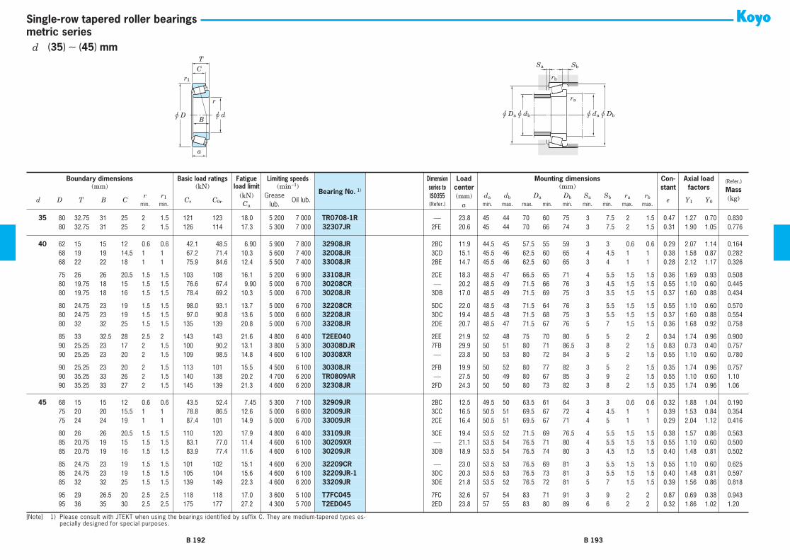
r
r1
u d
C
B
T
u D
a
u da u Dbu dbu Da
ra
Sa Sb
rb
metric seriesSingle-row tapered roller bearings
35 80 32.75 31 25 2 1.5 121 123 18.0 5 200 7 000 TR0708-1R ⎯ 23.8 45 44 70 60 75 3 7.5 2 1.5 0.47 1.27 0.70 0.83035 80 32.75 31 25 2 1.5 126 114 17.3 5 300 7 000 32307JR 2FE 20.6 45 44 70 66 74 3 7.5 2 1.5 0.31 1.90 1.05 0.776
40 62 15 15 12 0.6 0.6 42.1 48.5 6.90 5 900 7 800 32908JR 2BC 11.9 44.5 45 57.5 55 59 3 3 0.6 0.6 0.29 2.07 1.14 0.16440 68 19 19 14.5 1 1 67.2 71.4 10.3 5 600 7 400 32008JR 3CD 15.1 45.5 46 62.5 60 65 4 4.5 1 1 0.38 1.58 0.87 0.28240 68 22 22 18 1 1 75.9 84.6 12.4 5 500 7 400 33008JR 2BE 14.7 45.5 46 62.5 60 65 3 4 1 1 0.28 2.12 1.17 0.326
40 75 26 26 20.5 1.5 1.5 103 108 16.1 5 200 6 900 33108JR 2CE 18.3 48.5 47 66.5 65 71 4 5.5 1.5 1.5 0.36 1.69 0.93 0.50840 80 19.75 18 15 1.5 1.5 76.6 67.4 9.90 5 000 6 700 30208CR ⎯ 20.2 48.5 49 71.5 66 76 3 4.5 1.5 1.5 0.55 1.10 0.60 0.44540 80 19.75 18 16 1.5 1.5 78.4 69.2 10.3 5 000 6 700 30208JR 3DB 17.0 48.5 49 71.5 69 75 3 3.5 1.5 1.5 0.37 1.60 0.88 0.434
40 80 24.75 23 19 1.5 1.5 98.0 93.1 13.7 5 000 6 700 32208CR 5DC 22.0 48.5 48 71.5 64 76 3 5.5 1.5 1.5 0.55 1.10 0.60 0.57040 80 24.75 23 19 1.5 1.5 97.0 90.8 13.6 5 000 6 600 32208JR 3DC 19.4 48.5 48 71.5 68 75 3 5.5 1.5 1.5 0.37 1.60 0.88 0.55440 80 32 32 25 1.5 1.5 135 139 20.8 5 000 6 700 33208JR 2DE 20.7 48.5 47 71.5 67 76 5 7 1.5 1.5 0.36 1.68 0.92 0.758
40 85 33 32.5 28 2.5 2 143 143 21.6 4 800 6 400 T2EE040 2EE 21.9 52 48 75 70 80 5 5 2 2 0.34 1.74 0.96 0.90040 90 25.25 23 17 2 1.5 100 90.2 13.1 3 800 5 300 30308DJR 7FB 29.9 50 51 80 71 86.5 3 8 2 1.5 0.83 0.73 0.40 0.75740 90 25.25 23 20 2 1.5 109 98.5 14.8 4 600 6 100 30308XR ⎯ 23.8 50 53 80 72 84 3 5 2 1.5 0.55 1.10 0.60 0.780
40 90 25.25 23 20 2 1.5 113 101 15.5 4 500 6 100 30308JR 2FB 19.9 50 52 80 77 82 3 5 2 1.5 0.35 1.74 0.96 0.75740 90 35.25 33 26 2 1.5 140 138 20.2 4 700 6 200 TR0809AR ⎯ 27.5 50 49 80 67 85 3 9 2 1.5 0.55 1.10 0.60 1.1040 90 35.25 33 27 2 1.5 145 139 21.3 4 600 6 200 32308JR 2FD 24.3 50 50 80 73 82 3 8 2 1.5 0.35 1.74 0.96 1.06
45 68 15 15 12 0.6 0.6 43.5 52.4 7.45 5 300 7 100 32909JR 2BC 12.5 49.5 50 63.5 61 64 3 3 0.6 0.6 0.32 1.88 1.04 0.19045 75 20 20 15.5 1 1 78.8 86.5 12.6 5 000 6 600 32009JR 3CC 16.5 50.5 51 69.5 67 72 4 4.5 1 1 0.39 1.53 0.84 0.35445 75 24 24 19 1 1 87.4 101 14.9 5 000 6 700 33009JR 2CE 16.4 50.5 51 69.5 67 71 4 5 1 1 0.29 2.04 1.12 0.416
45 80 26 26 20.5 1.5 1.5 110 120 17.9 4 800 6 400 33109JR 3CE 19.4 53.5 52 71.5 69 76.5 4 5.5 1.5 1.5 0.38 1.57 0.86 0.56345 85 20.75 19 15 1.5 1.5 83.1 77.0 11.4 4 600 6 100 30209XR ⎯ 21.1 53.5 54 76.5 71 80 4 5.5 1.5 1.5 0.55 1.10 0.60 0.50045 85 20.75 19 16 1.5 1.5 83.9 77.4 11.6 4 600 6 100 30209JR 3DB 18.9 53.5 54 76.5 74 80 3 4.5 1.5 1.5 0.40 1.48 0.81 0.502
45 85 24.75 23 19 1.5 1.5 101 102 15.1 4 600 6 200 32209CR ⎯ 23.0 53.5 53 76.5 69 81 3 5.5 1.5 1.5 0.55 1.10 0.60 0.62545 85 24.75 23 19 1.5 1.5 105 104 15.6 4 600 6 100 32209JR-1 3DC 20.3 53.5 53 76.5 73 81 3 5.5 1.5 1.5 0.40 1.48 0.81 0.59745 85 32 32 25 1.5 1.5 139 149 22.3 4 600 6 200 33209JR 3DE 21.8 53.5 52 76.5 72 81 5 7 1.5 1.5 0.39 1.56 0.86 0.818
45 95 29 26.5 20 2.5 2.5 118 118 17.0 3 600 5 100 T7FC045 7FC 32.6 57 54 83 71 91 3 9 2 2 0.87 0.69 0.38 0.94345 95 36 35 30 2.5 2.5 175 177 27.2 4 300 5 700 T2ED045 2ED 23.8 57 55 83 80 89 6 6 2 2 0.32 1.86 1.02 1.20
Boundary dimensions Basic load ratings Fatigue Limiting speeds
Bearing No. 1)
Dimensionseries toISO355
Loadcenter(mm)
a
Mounting dimensions Con-stant
Axial load factors
(Refer.)
Mass(kg)
(mm) (kN) load limit (min−1) (mm)
d D T B Cr r1 Cr C0r
(kN) Greaselub.
Oil lub.da db Da Db Sa Sb ra rb e Y1 Y0min. min. Cu (Refer.) min. max. max. min. min. min. min. max. max.
[Note] 1) Please consult with JTEKT when using the bearings identified by suffix C. They are medium-tapered types es-pecially designed for special purposes.
B 192 B 193
d (35) ∼ (45) mm

r
r1
u d
C
B
T
u D
a
u da u Dbu dbu Da
ra
Sa Sb
rb
metric seriesSingle-row tapered roller bearings
45 100 27.25 25 18 2 1.5 119 107 15.8 3 400 4 700 30309DJR 7FB 32.9 55 56 90 79 96 3 9 2 1.5 0.83 0.73 0.40 0.97345 100 27.25 25 20 2 1.5 136 119 18.1 4 100 5 500 30309CR ⎯ 25.7 55 57 90 81 94 4 7 2 1.5 0.55 1.10 0.60 1.0045 100 27.25 25 22 2 1.5 141 128 19.9 4 100 5 400 30309JR 2FB 21.3 55 59 90 86 93 3 5 2 1.5 0.35 1.74 0.96 1.01
45 100 38.25 36 29 2 1.5 181 182 27.0 4 200 5 600 32309CR ⎯ 30.3 55 56 90 76 95 4 9 2 1.5 0.55 1.10 0.60 1.4545 100 38.25 36 30 2 1.5 183 180 27.7 4 100 5 500 32309JR 2FD 26.8 55 56 90 82 93 3 8 2 1.5 0.35 1.74 0.96 1.43
50 72 15 15 12 0.6 0.6 45.0 56.3 8.00 4 900 6 600 32910JR 2BC 13.7 54.5 55 67.5 65 69 3 3 0.6 0.6 0.34 1.76 0.97 0.19550 80 20 20 15.5 1 1 82.7 94.5 13.8 4 600 6 100 32010JR 3CC 17.7 55.5 56 74.5 72 77 4 4.5 1 1 0.42 1.42 0.78 0.38950 80 24 24 19 1 1 91.8 110 16.3 4 600 6 100 33010JR 2CE 17.4 55.5 56 74.5 72 76 4 5 1 1 0.32 1.90 1.04 0.451
50 85 26 26 20 1.5 1.5 112 127 18.9 4 400 5 900 33110JR 3CE 20.6 58.5 56 76.5 74 81.5 4 6 1.5 1.5 0.41 1.46 0.80 0.59450 90 21.75 20 16 1.5 1.5 96.7 95.8 14.3 4 300 5 700 30210CR ⎯ 22.7 58.5 58 81.5 76 86 4 5.5 1.5 1.5 0.55 1.10 0.60 0.59050 90 21.75 20 17 1.5 1.5 95.6 91.7 13.8 4 300 5 700 30210JR 3DB 20.1 58.5 58 81.5 79 85 3 4.5 1.5 1.5 0.42 1.43 0.79 0.566
50 90 24.75 23 19 1.5 1.5 106 113 16.7 4 300 5 700 32210CR ⎯ 24.0 58.5 58 81.5 74 86 3 5.5 1.5 1.5 0.55 1.10 0.60 0.67550 90 24.75 23 19 1.5 1.5 106 105 15.9 4 300 5 700 32210JR 3DC 20.6 58.5 58 81.5 78 85 3 5.5 1.5 1.5 0.42 1.43 0.79 0.64350 90 32 32 24.5 1.5 1.5 150 167 25.0 4 300 5 700 33210JR 3DE 23.1 58.5 57 81.5 77 86.5 5 7.5 1.5 1.5 0.41 1.45 0.80 0.887
50 100 36 35 30 2.5 2.5 196 196 30.2 4 100 5 400 T2ED050 2ED 24.5 62 58 88 84 94 6 6 2 2 0.34 1.75 0.96 1.2850 105 32 29 22 3 3 141 140 20.3 3 300 4 600 T7FC050 7FC 35.9 64 59 91 78 100 4 10 2.5 2.5 0.87 0.69 0.38 1.2550 110 29.25 27 19 2.5 2 144 133 19.8 3 100 4 300 30310DJR 7FB 35.0 62 62 98 87 105 3 10 2 2 0.83 0.73 0.40 1.25
50 110 29.25 27 20 2.5 2 155 143 21.9 3 700 4 900 30310CR ⎯ 27.5 62 64 98 90 103 4 9 2 2 0.55 1.10 0.60 1.2550 110 29.25 27 23 2.5 2 172 152 24.0 3 700 4 900 30310JR 2FB 22.9 62 65 98 95 102 3 6 2 2 0.35 1.74 0.96 1.3250 110 42.25 40 33 2.5 2 214 234 34.6 3 800 5 100 32310CR 5FD 33.4 62 61 98 81 103 4 9 2 2 0.55 1.10 0.60 2.00
50 110 42.25 40 33 2.5 2 221 220 34.2 3 700 5 000 32310JR 2FD 29.4 62 62 98 90 102 3 9 2 2 0.35 1.74 0.96 1.89
55 80 17 17 14 1 1 55.8 73.3 10.6 4 400 5 900 32911JR 2BC 14.5 61 61 74 72 76 3 3 1 1 0.31 1.94 1.07 0.28555 90 23 23 17.5 1.5 1.5 106 121 18.2 4 100 5 500 32011JR 3CC 19.8 63.5 63 81.5 81 86 4 5.5 1.5 1.5 0.41 1.48 0.81 0.56955 90 27 27 21 1.5 1.5 121 149 22.6 4 100 5 400 33011JR 2CE 19.3 63.5 63 81.5 81 86 5 6 1.5 1.5 0.31 1.92 1.06 0.672
55 95 30 30 23 1.5 1.5 145 161 24.6 4 000 5 300 33111JR 3CE 22.5 63.5 62 86.5 83 91 5 7 1.5 1.5 0.37 1.60 0.88 0.86855 100 22.75 21 17 2 1.5 112 108 16.2 3 900 5 200 30211CR ⎯ 24.3 65 63 90 84 95 4 5.5 2 1.5 0.55 1.10 0.60 0.75055 100 22.75 21 18 2 1.5 118 113 17.3 3 900 5 200 30211JR 3DB 20.7 65 64 90 88 94 4 4.5 2 1.5 0.40 1.48 0.81 0.732
55 100 26.75 25 21 2 1.5 134 135 20.4 3 900 5 200 32211CR ⎯ 25.9 65 64 90 83 96 4 5.5 2 1.5 0.55 1.10 0.60 0.875
Boundary dimensions Basic load ratings Fatigue Limiting speeds
Bearing No. 1)
Dimensionseries toISO355
Loadcenter(mm)
a
Mounting dimensions Con-stant
Axial load factors
(Refer.)
Mass(kg)
(mm) (kN) load limit (min−1) (mm)
d D T B Cr r1 Cr C0r
(kN) Greaselub.
Oil lub.da db Da Db Sa Sb ra rb e Y1 Y0min. min. Cu (Refer.) min. max. max. min. min. min. min. max. max.
[Note] 1) Please consult with JTEKT when using the bearings identified by suffix C. They are medium-tapered types es-pecially designed for special purposes.
B 194 B 195
d (45) ∼ (55) mm
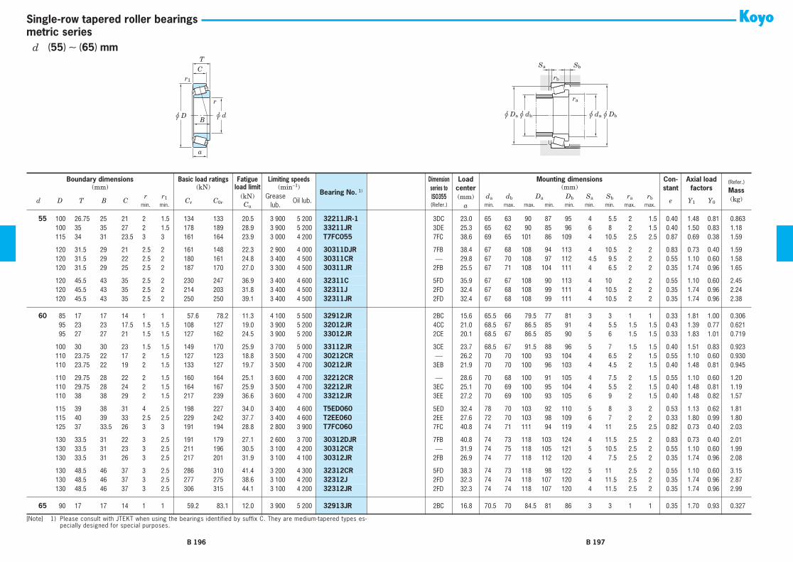
r
r1
u d
C
B
T
u D
a
u da u Dbu dbu Da
ra
Sa Sb
rb
metric seriesSingle-row tapered roller bearings
55 100 26.75 25 21 2 1.5 134 133 20.5 3 900 5 200 32211JR-1 3DC 23.0 65 63 90 87 95 4 5.5 2 1.5 0.40 1.48 0.81 0.86355 100 35 35 27 2 1.5 178 189 28.9 3 900 5 200 33211JR 3DE 25.3 65 62 90 85 96 6 8 2 1.5 0.40 1.50 0.83 1.1855 115 34 31 23.5 3 3 161 164 23.9 3 000 4 200 T7FC055 7FC 38.6 69 65 101 86 109 4 10.5 2.5 2.5 0.87 0.69 0.38 1.59
55 120 31.5 29 21 2.5 2 161 148 22.3 2 900 4 000 30311DJR 7FB 38.4 67 68 108 94 113 4 10.5 2 2 0.83 0.73 0.40 1.5955 120 31.5 29 22 2.5 2 180 161 24.8 3 400 4 500 30311CR ⎯ 29.8 67 70 108 97 112 4.5 9.5 2 2 0.55 1.10 0.60 1.5855 120 31.5 29 25 2.5 2 187 170 27.0 3 300 4 500 30311JR 2FB 25.5 67 71 108 104 111 4 6.5 2 2 0.35 1.74 0.96 1.65
55 120 45.5 43 35 2.5 2 230 247 36.9 3 400 4 600 32311C 5FD 35.9 67 67 108 90 113 4 10 2 2 0.55 1.10 0.60 2.4555 120 45.5 43 35 2.5 2 214 203 31.8 3 400 4 500 32311J 2FD 32.4 67 68 108 99 111 4 10.5 2 2 0.35 1.74 0.96 2.2455 120 45.5 43 35 2.5 2 250 250 39.1 3 400 4 500 32311JR 2FD 32.4 67 68 108 99 111 4 10.5 2 2 0.35 1.74 0.96 2.38
60 85 17 17 14 1 1 57.6 78.2 11.3 4 100 5 500 32912JR 2BC 15.6 65.5 66 79.5 77 81 3 3 1 1 0.33 1.81 1.00 0.30660 95 23 23 17.5 1.5 1.5 108 127 19.0 3 900 5 200 32012JR 4CC 21.0 68.5 67 86.5 85 91 4 5.5 1.5 1.5 0.43 1.39 0.77 0.62160 95 27 27 21 1.5 1.5 127 162 24.5 3 900 5 200 33012JR 2CE 20.1 68.5 67 86.5 85 90 5 6 1.5 1.5 0.33 1.83 1.01 0.719
60 100 30 30 23 1.5 1.5 149 170 25.9 3 700 5 000 33112JR 3CE 23.7 68.5 67 91.5 88 96 5 7 1.5 1.5 0.40 1.51 0.83 0.92360 110 23.75 22 17 2 1.5 127 123 18.8 3 500 4 700 30212CR ⎯ 26.2 70 70 100 93 104 4 6.5 2 1.5 0.55 1.10 0.60 0.93060 110 23.75 22 19 2 1.5 133 127 19.7 3 500 4 700 30212JR 3EB 21.9 70 70 100 96 103 4 4.5 2 1.5 0.40 1.48 0.81 0.945
60 110 29.75 28 22 2 1.5 160 164 25.1 3 600 4 700 32212CR ⎯ 28.6 70 68 100 91 105 4 7.5 2 1.5 0.55 1.10 0.60 1.2060 110 29.75 28 24 2 1.5 164 167 25.9 3 500 4 700 32212JR 3EC 25.1 70 69 100 95 104 4 5.5 2 1.5 0.40 1.48 0.81 1.1960 110 38 38 29 2 1.5 217 239 36.6 3 600 4 700 33212JR 3EE 27.2 70 69 100 93 105 6 9 2 1.5 0.40 1.48 0.82 1.57
60 115 39 38 31 4 2.5 198 227 34.0 3 400 4 600 T5ED060 5ED 32.4 78 70 103 92 110 5 8 3 2 0.53 1.13 0.62 1.8160 115 40 39 33 2.5 2.5 229 242 37.7 3 400 4 600 T2EE060 2EE 27.6 72 70 103 98 109 6 7 2 2 0.33 1.80 0.99 1.8060 125 37 33.5 26 3 3 191 194 28.8 2 800 3 900 T7FC060 7FC 40.8 74 71 111 94 119 4 11 2.5 2.5 0.82 0.73 0.40 2.03
60 130 33.5 31 22 3 2.5 191 179 27.1 2 600 3 700 30312DJR 7FB 40.8 74 73 118 103 124 4 11.5 2.5 2 0.83 0.73 0.40 2.0160 130 33.5 31 23 3 2.5 211 196 30.5 3 100 4 200 30312CR ⎯ 31.9 74 75 118 105 121 5 10.5 2.5 2 0.55 1.10 0.60 1.9960 130 33.5 31 26 3 2.5 217 201 31.9 3 100 4 100 30312JR 2FB 26.9 74 77 118 112 120 4 7.5 2.5 2 0.35 1.74 0.96 2.08
60 130 48.5 46 37 3 2.5 286 310 41.4 3 200 4 300 32312CR 5FD 38.3 74 73 118 98 122 5 11 2.5 2 0.55 1.10 0.60 3.1560 130 48.5 46 37 3 2.5 277 275 38.6 3 100 4 200 32312J 2FD 32.3 74 74 118 107 120 4 11.5 2.5 2 0.35 1.74 0.96 2.8760 130 48.5 46 37 3 2.5 306 315 44.1 3 100 4 200 32312JR 2FD 32.3 74 74 118 107 120 4 11.5 2.5 2 0.35 1.74 0.96 2.99
65 90 17 17 14 1 1 59.2 83.1 12.0 3 900 5 200 32913JR 2BC 16.8 70.5 70 84.5 81 86 3 3 1 1 0.35 1.70 0.93 0.327
Boundary dimensions Basic load ratings Fatigue Limiting speeds
Bearing No. 1)
Dimensionseries toISO355
Loadcenter(mm)
a
Mounting dimensions Con-stant
Axial load factors
(Refer.)
Mass(kg)
(mm) (kN) load limit (min−1) (mm)
d D T B Cr r1 Cr C0r
(kN) Greaselub.
Oil lub.da db Da Db Sa Sb ra rb e Y1 Y0min. min. Cu (Refer.) min. max. max. min. min. min. min. max. max.
[Note] 1) Please consult with JTEKT when using the bearings identified by suffix C. They are medium-tapered types es-pecially designed for special purposes.
B 196 B 197
d (55) ∼ (65) mm
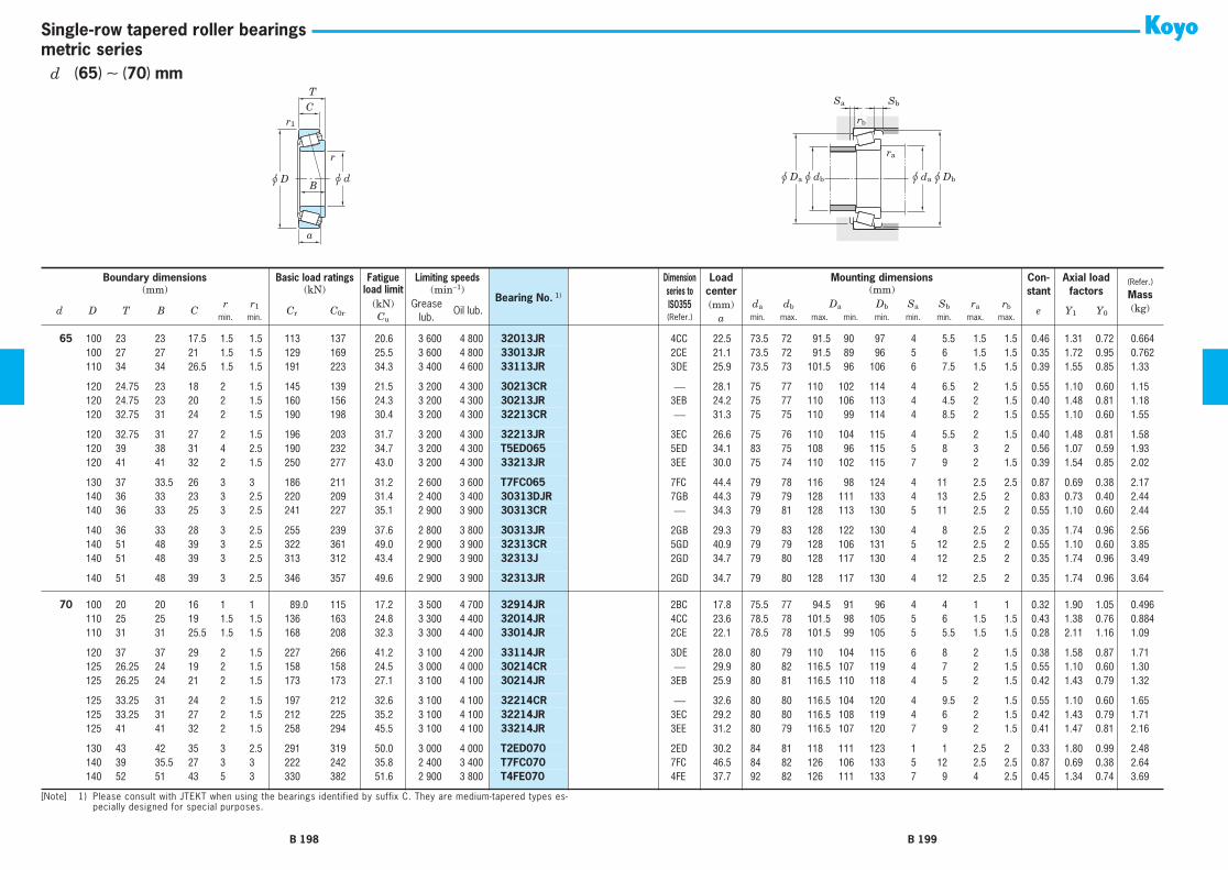
r
r1
u d
C
B
T
u D
a
u da u Dbu dbu Da
ra
Sa Sb
rb
metric seriesSingle-row tapered roller bearings
65 100 23 23 17.5 1.5 1.5 113 137 20.6 3 600 4 800 32013JR 4CC 22.5 73.5 72 91.5 90 97 4 5.5 1.5 1.5 0.46 1.31 0.72 0.66465 100 27 27 21 1.5 1.5 129 169 25.5 3 600 4 800 33013JR 2CE 21.1 73.5 72 91.5 89 96 5 6 1.5 1.5 0.35 1.72 0.95 0.76265 110 34 34 26.5 1.5 1.5 191 223 34.3 3 400 4 600 33113JR 3DE 25.9 73.5 73 101.5 96 106 6 7.5 1.5 1.5 0.39 1.55 0.85 1.33
65 120 24.75 23 18 2 1.5 145 139 21.5 3 200 4 300 30213CR ⎯ 28.1 75 77 110 102 114 4 6.5 2 1.5 0.55 1.10 0.60 1.1565 120 24.75 23 20 2 1.5 160 156 24.3 3 200 4 300 30213JR 3EB 24.2 75 77 110 106 113 4 4.5 2 1.5 0.40 1.48 0.81 1.1865 120 32.75 31 24 2 1.5 190 198 30.4 3 200 4 300 32213CR ⎯ 31.3 75 75 110 99 114 4 8.5 2 1.5 0.55 1.10 0.60 1.55
65 120 32.75 31 27 2 1.5 196 203 31.7 3 200 4 300 32213JR 3EC 26.6 75 76 110 104 115 4 5.5 2 1.5 0.40 1.48 0.81 1.5865 120 39 38 31 4 2.5 190 232 34.7 3 200 4 300 T5ED065 5ED 34.1 83 75 108 96 115 5 8 3 2 0.56 1.07 0.59 1.9365 120 41 41 32 2 1.5 250 277 43.0 3 200 4 300 33213JR 3EE 30.0 75 74 110 102 115 7 9 2 1.5 0.39 1.54 0.85 2.02
65 130 37 33.5 26 3 3 186 211 31.2 2 600 3 600 T7FC065 7FC 44.4 79 78 116 98 124 4 11 2.5 2.5 0.87 0.69 0.38 2.1765 140 36 33 23 3 2.5 220 209 31.4 2 400 3 400 30313DJR 7GB 44.3 79 79 128 111 133 4 13 2.5 2 0.83 0.73 0.40 2.4465 140 36 33 25 3 2.5 241 227 35.1 2 900 3 900 30313CR ⎯ 34.3 79 81 128 113 130 5 11 2.5 2 0.55 1.10 0.60 2.44
65 140 36 33 28 3 2.5 255 239 37.6 2 800 3 800 30313JR 2GB 29.3 79 83 128 122 130 4 8 2.5 2 0.35 1.74 0.96 2.5665 140 51 48 39 3 2.5 322 361 49.0 2 900 3 900 32313CR 5GD 40.9 79 79 128 106 131 5 12 2.5 2 0.55 1.10 0.60 3.8565 140 51 48 39 3 2.5 313 312 43.4 2 900 3 900 32313J 2GD 34.7 79 80 128 117 130 4 12 2.5 2 0.35 1.74 0.96 3.49
65 140 51 48 39 3 2.5 346 357 49.6 2 900 3 900 32313JR 2GD 34.7 79 80 128 117 130 4 12 2.5 2 0.35 1.74 0.96 3.64
70 100 20 20 16 1 1 89.0 115 17.2 3 500 4 700 32914JR 2BC 17.8 75.5 77 94.5 91 96 4 4 1 1 0.32 1.90 1.05 0.49670 110 25 25 19 1.5 1.5 136 163 24.8 3 300 4 400 32014JR 4CC 23.6 78.5 78 101.5 98 105 5 6 1.5 1.5 0.43 1.38 0.76 0.88470 110 31 31 25.5 1.5 1.5 168 208 32.3 3 300 4 400 33014JR 2CE 22.1 78.5 78 101.5 99 105 5 5.5 1.5 1.5 0.28 2.11 1.16 1.09
70 120 37 37 29 2 1.5 227 266 41.2 3 100 4 200 33114JR 3DE 28.0 80 79 110 104 115 6 8 2 1.5 0.38 1.58 0.87 1.7170 125 26.25 24 19 2 1.5 158 158 24.5 3 000 4 000 30214CR ⎯ 29.9 80 82 116.5 107 119 4 7 2 1.5 0.55 1.10 0.60 1.3070 125 26.25 24 21 2 1.5 173 173 27.1 3 100 4 100 30214JR 3EB 25.9 80 81 116.5 110 118 4 5 2 1.5 0.42 1.43 0.79 1.32
70 125 33.25 31 24 2 1.5 197 212 32.6 3 100 4 100 32214CR ⎯ 32.6 80 80 116.5 104 120 4 9.5 2 1.5 0.55 1.10 0.60 1.6570 125 33.25 31 27 2 1.5 212 225 35.2 3 100 4 100 32214JR 3EC 29.2 80 80 116.5 108 119 4 6 2 1.5 0.42 1.43 0.79 1.7170 125 41 41 32 2 1.5 258 294 45.5 3 100 4 100 33214JR 3EE 31.2 80 79 116.5 107 120 7 9 2 1.5 0.41 1.47 0.81 2.16
70 130 43 42 35 3 2.5 291 319 50.0 3 000 4 000 T2ED070 2ED 30.2 84 81 118 111 123 1 1 2.5 2 0.33 1.80 0.99 2.4870 140 39 35.5 27 3 3 222 242 35.8 2 400 3 400 T7FC070 7FC 46.5 84 82 126 106 133 5 12 2.5 2.5 0.87 0.69 0.38 2.6470 140 52 51 43 5 3 330 382 51.6 2 900 3 800 T4FE070 4FE 37.7 92 82 126 111 133 7 9 4 2.5 0.45 1.34 0.74 3.69
Boundary dimensions Basic load ratings Fatigue Limiting speeds
Bearing No. 1)
Dimensionseries toISO355
Loadcenter(mm)
a
Mounting dimensions Con-stant
Axial load factors
(Refer.)
Mass(kg)
(mm) (kN) load limit (min−1) (mm)
d D T B Cr r1 Cr C0r
(kN) Greaselub.
Oil lub.da db Da Db Sa Sb ra rb e Y1 Y0min. min. Cu (Refer.) min. max. max. min. min. min. min. max. max.
[Note] 1) Please consult with JTEKT when using the bearings identified by suffix C. They are medium-tapered types es-pecially designed for special purposes.
B 198 B 199
d (65) ∼ (70) mm

r
r1
u d
C
B
T
u D
a
u da u Dbu dbu Da
ra
Sa Sb
rb
metric seriesSingle-row tapered roller bearings
70 150 38 35 25 3 2.5 246 235 34.9 2 300 3 200 30314DJR 7GB 47.1 84 84 138 118 142 4 13 2.5 2 0.83 0.73 0.40 2.9770 150 38 35 30 3 2.5 280 256 36.0 2 700 3 600 30314CR ⎯ 37.0 84 87 138 123 141 6 8 2.5 2 0.55 1.10 0.60 3.1070 150 38 35 30 3 2.5 288 273 42.2 2 600 3 500 30314JR 2GB 30.5 84 89 138 130 140 4 8 2.5 2 0.35 1.74 0.96 3.08
70 150 54 51 42 3 2.5 321 315 44.1 2 700 3 600 32314 ⎯ 37.0 84 86 138 125 140 4 12 2.5 2 0.35 1.73 0.95 4.1170 150 54 51 42 3 2.5 371 391 51.4 2 700 3 600 32314C 5GD 44.4 84 84 138 115 142 5 12 2.5 2 0.55 1.10 0.60 4.5070 150 54 51 42 3 2.5 396 414 57.2 2 700 3 600 32314JR 2GD 37.4 84 86 138 125 140 4 12 2.5 2 0.35 1.74 0.96 4.50
75 105 20 20 16 1 1 92.2 123 18.4 3 300 4 400 32915JR 2BC 18.9 80.5 81 99.5 96 101 4 4 1 1 0.33 1.80 0.99 0.52675 115 25 25 19 1.5 1.5 139 169 25.8 3 100 4 200 32015JR 4CC 25.1 83.5 83 106.5 103 110 5 6 1.5 1.5 0.46 1.31 0.72 0.93075 115 31 31 25.5 1.5 1.5 177 225 35.0 3 200 4 200 33015JR 2CE 22.9 83.5 83 106.5 104 110 6 5.5 1.5 1.5 0.30 2.01 1.11 1.16
75 125 37 37 29 2 1.5 234 280 43.4 3 000 4 000 33115JR 3DE 29.3 85 84 116.5 109 120 6 8 2 1.5 0.40 1.51 0.83 1.8475 130 27.25 25 20 2 1.5 171 178 27.4 2 900 3 800 30215CR ⎯ 31.0 85 87 121.5 111 124 5 7 2 1.5 0.55 1.10 0.60 1.4075 130 27.25 25 22 2 1.5 178 181 28.2 2 900 3 900 30215JR 4DB 27.6 85 86 121.5 115 124 4 5 2 1.5 0.44 1.38 0.76 1.42
75 130 33.25 31 24 2 1.5 204 225 34.5 2 900 3 900 32215CR ⎯ 33.7 85 85 121.5 109 125 4 9 2 1.5 0.55 1.10 0.60 1.7575 130 33.25 31 27 2 1.5 218 234 36.4 2 900 3 900 32215JR 4DC 30.2 85 85 121.5 114 125 4 6 2 1.5 0.44 1.38 0.76 1.7775 130 41 41 31 2 1.5 266 310 47.7 2 900 3 900 33215JR 3EE 32.5 85 83 121.5 111 125 7 10 2 1.5 0.43 1.40 0.77 2.26
75 150 42 38 29 3 3 240 270 39.0 2 200 3 100 T7FC075 7FC 50.6 89 89 136 114 143 5 13 2.5 2.5 0.87 0.69 0.38 3.2475 160 40 37 26 3 2.5 266 254 34.2 2 100 2 900 30315DJR 7GB 49.9 89 91 148 127 151 6 14 2.5 2 0.83 0.73 0.40 3.4575 160 40 37 26 3 2.5 277 266 36.9 2 100 2 900 30315DR ⎯ 48.8 89 91 148 127 151 6 14 2.5 2 0.81 0.74 0.41 3.48
75 160 40 37 31 3 2.5 310 296 42.1 2 500 3 400 30315CR ⎯ 39.2 89 94 148 130 150 6 9 2.5 2 0.55 1.10 0.60 3.8075 160 40 37 31 3 2.5 325 311 44.9 2 500 3 300 30315JR 2GB 32.5 89 95 148 139 149 4 9 2.5 2 0.35 1.74 0.96 3.6575 160 40 37 31 3 2.5 313 298 43.3 2 500 3 300 30315R ⎯ 31.9 89 95 148 139 149 4 9 2.5 2 0.35 1.73 0.95 3.52
75 160 58 55 43 3 2.5 447 474 61.4 2 500 3 400 32315CR ⎯ 46.6 89 90 148 125 154 6 15 2.5 2 0.55 1.10 0.60 5.5075 160 58 55 45 3 2.5 454 481 64.6 2 500 3 300 32315JR 2GD 40.0 89 91 148 133 149 4 13 2.5 2 0.35 1.74 0.96 5.4175 160 58 55 45 3 2.5 425 444 60.3 2 500 3 300 32315R ⎯ 39.5 89 91 148 133 149 4 13 2.5 2 0.35 1.73 0.95 5.30
80 110 20 20 16 1 1 95.1 131 19.5 3 100 4 200 32916JR 2BC 20.1 85.5 86 104.5 101 106 4 4 1 1 0.35 1.71 0.94 0.55680 125 29 29 22 1.5 1.5 185 225 34.6 2 900 3 900 32016JR 3CC 26.7 88.5 89 116.5 112 120 6 7 1.5 1.5 0.42 1.42 0.78 1.3280 125 36 36 29.5 1.5 1.5 218 288 44.8 2 900 3 900 33016JR 2CE 25.1 88.5 90 116.5 112 119 6 6.5 1.5 1.5 0.28 2.16 1.19 1.63
80 130 37 37 29 2 1.5 240 294 44.9 2 800 3 800 33116JR 3DE 30.5 90 89 121.5 114 126 6 8 2 1.5 0.42 1.44 0.79 1.93
Boundary dimensions Basic load ratings Fatigue Limiting speeds
Bearing No. 1)
Dimensionseries toISO355
Loadcenter(mm)
a
Mounting dimensions Con-stant
Axial load factors
(Refer.)
Mass(kg)
(mm) (kN) load limit (min−1) (mm)
d D T B Cr r1 Cr C0r
(kN) Greaselub.
Oil lub.da db Da Db Sa Sb ra rb e Y1 Y0min. min. Cu (Refer.) min. max. max. min. min. min. min. max. max.
[Note] 1) Please consult with JTEKT when using the bearings identified by suffix C. They are medium-tapered types es-pecially designed for special purposes.
B 200 B 201
d (70) ∼ (80) mm

r
r1
u d
C
B
T
u D
a
u da u Dbu dbu Da
ra
Sa Sb
rb
metric seriesSingle-row tapered roller bearings
80 140 28.25 26 22 2.5 2 202 202 31.2 2 700 3 600 30216JR 3EB 28.6 92 91 130 124 132 4 6 2 2 0.42 1.43 0.79 1.7280 140 35.25 33 28 2.5 2 253 271 41.5 2 700 3 600 32216JR 3EC 31.7 92 90 130 122 134 4 7 2 2 0.42 1.43 0.79 2.1780 140 46 46 35 2.5 2 313 371 56.1 2 700 3 600 33216JR 3EE 35.7 92 89 130 119 135 7 11 2 2 0.43 1.41 0.78 2.99
80 145 46 45 38 3 2.5 333 381 52.0 2 600 3 500 T2ED080 2ED 32.7 94 92 133 125 137 7 8 2.5 2 0.32 1.88 1.03 3.2080 170 42.5 39 27 3 2.5 294 282 38.7 2 000 2 800 30316DJR 7GB 53.5 94 97 158 134 159 6 15.5 2.5 2 0.83 0.73 0.40 4.1280 170 42.5 39 33 3 2.5 368 355 49.9 2 300 3 100 30316JR 2GB 34.8 94 102 158 148 159 4 9.5 2.5 2 0.35 1.74 0.96 4.46
80 170 42.5 39 33 3 2.5 345 330 47.1 2 300 3 100 30316R ⎯ 33.9 94 102 158 148 159 4 9.5 2.5 2 0.35 1.73 0.95 4.2680 170 61.5 58 48 3 2.5 434 440 58.6 2 300 3 100 32316J 2GD 43.5 94 98 158 142 159 4 13.5 2.5 2 0.35 1.74 0.96 6.0480 170 61.5 58 48 3 2.5 480 503 67.0 2 300 3 100 32316JR 2GD 43.5 94 98 158 142 159 4 13.5 2.5 2 0.35 1.74 0.96 6.31
85 120 23 23 18 1.5 1.5 122 165 25.0 2 900 3 900 32917JR 2BC 21.2 93.5 93 111.5 109 115 5 5 1.5 1.5 0.33 1.83 1.01 0.79485 130 29 29 22 1.5 1.5 189 234 35.5 2 800 3 700 32017JR 4CC 28.0 93.5 94 121.5 117 125 6 7 1.5 1.5 0.44 1.36 0.75 1.3885 130 36 36 29.5 1.5 1.5 222 300 46.0 2 800 3 700 33017JR 2CE 26.3 93.5 94 121.5 118 125 6 6.5 1.5 1.5 0.29 2.06 1.13 1.72
85 140 41 41 32 2.5 2 282 346 52.2 2 600 3 500 33117JR 3DE 33.2 97 95 130 122 135 7 9 2 2 0.41 1.48 0.81 2.4385 150 30.5 28 24 2.5 2 228 231 35.1 2 500 3 400 30217JR 3EB 30.4 97 97 140 132 141 5 6.5 2 2 0.42 1.43 0.79 2.1785 150 38.5 36 30 2.5 2 290 315 47.5 2 500 3 400 32217JR 3EC 34.2 97 96 140 130 142 5 8.5 2 2 0.42 1.43 0.79 2.80
85 150 49 49 37 2.5 2 368 439 59.1 2 500 3 400 33217JR 3EE 37.1 97 95 140 128 144 7 12 2 2 0.42 1.43 0.79 3.6385 180 44.5 41 28 4 3 288 265 36.0 1 900 2 600 30317D ⎯ 56.0 103 103 166 143 169 6 16.5 3 2.5 0.81 0.74 0.41 4.5485 180 44.5 41 28 4 3 328 317 42.6 1 900 2 600 30317DJR 7GB 56.3 103 103 166 143 169 6 16.5 3 2.5 0.83 0.73 0.40 4.81
85 180 44.5 41 34 4 3 396 384 53.0 2 200 2 900 30317JR 2GB 36.0 103 107 166 156 167 5 10.5 3 2.5 0.35 1.74 0.96 5.1585 180 44.5 41 34 4 3 381 367 51.1 2 200 2 900 30317R ⎯ 35.8 103 107 166 156 167 5 10.5 3 2.5 0.35 1.73 0.95 4.9785 180 63.5 60 49 4 3 549 587 77.6 2 200 3 000 32317JR 2GD 43.8 103 103 166 150 167 5 14.5 3 2.5 0.35 1.74 0.96 7.42
90 125 23 23 18 1.5 1.5 126 175 26.2 2 800 3 700 32918JR 2BC 22.3 98.5 97 116.5 114 120 5 5 1.5 1.5 0.34 1.75 0.96 0.83490 140 32 32 24 2 1.5 224 276 41.5 2 600 3 500 32018JR 3CC 29.8 100 100 131.5 125 134 6 8 2 1.5 0.42 1.42 0.78 1.8090 140 39 39 32.5 2 1.5 278 367 55.6 2 600 3 400 33018JR 2CE 27.1 100 100 131.5 127 135 7 6.5 2 1.5 0.27 2.23 1.23 2.22
90 150 45 45 35 2.5 2 324 413 61.1 2 500 3 300 33118JR 3DE 35.4 102 100 140 130 144 7 10 2 2 0.40 1.51 0.83 3.1390 155 46 46 38 3 3 342 405 54.1 2 400 3 200 T2ED090 2ED 33.5 104 102 141 135 147 7 8 2.5 2.5 0.33 1.84 1.01 3.4790 160 32.5 30 26 2.5 2 255 261 39.0 2 400 3 200 30218JR 3FB 32.6 102 103 150 140 150 5 6.5 2 2 0.42 1.43 0.79 2.65
90 160 42.5 40 34 2.5 2 329 362 53.7 2 400 3 200 32218JR 3FC 37.0 102 102 150 138 152 5 8.5 2 2 0.42 1.43 0.79 3.47
Boundary dimensions Basic load ratings Fatigue Limiting speeds
Bearing No. 1)
Dimensionseries toISO355
Loadcenter(mm)
a
Mounting dimensions Con-stant
Axial load factors
(Refer.)
Mass(kg)
(mm) (kN) load limit (min−1) (mm)
d D T B Cr r1 Cr C0r
(kN) Greaselub.
Oil lub.da db Da Db Sa Sb ra rb e Y1 Y0min. min. Cu (Refer.) min. max. max. min. min. min. min. max. max.
[Note] 1) Please consult with JTEKT when using the bearings identified by suffix C. They are medium-tapered types es-pecially designed for special purposes.
B 202 B 203
d (80) ∼ (90) mm

r
r1
u d
C
B
T
u D
a
u da u Dbu dbu Da
ra
Sa Sb
rb
metric seriesSingle-row tapered roller bearings
90 160 55 55 42 2.5 2 430 527 68.3 2 400 3 200 33218JR 3FE 40.8 102 101 150 135 154 9 13 2 2 0.42 1.43 0.78 4.7690 190 46.5 43 30 4 3 359 350 46.2 1 700 2 400 30318DJR 7GB 59.6 108 109 176 151 179 6 16.5 3 2.5 0.83 0.73 0.40 5.5790 190 46.5 43 30 4 3 352 336 44.9 1 700 2 400 30318DR ⎯ 59.1 108 109 176 151 179 6 16.5 3 2.5 0.81 0.74 0.41 5.60
90 190 46.5 43 36 4 3 432 420 57.1 2 100 2 700 30318JR 2GB 38.1 108 113 176 165 177 5 10.5 3 2.5 0.35 1.74 0.96 6.0490 190 46.5 43 36 4 3 421 407 55.5 2 100 2 700 30318R ⎯ 37.2 108 113 176 165 177 5 10.5 3 2.5 0.35 1.73 0.95 5.7890 190 67.5 64 53 4 3 577 614 78.7 2 100 2 800 32318JR 2GD 46.6 108 108 176 157 177 5 14.5 3 2.5 0.35 1.74 0.96 8.61
95 130 23 23 18 1.5 1.5 130 186 27.4 2 600 3 500 32919JR 2BC 23.5 103.5 102 121.5 119 125 5 5 1.5 1.5 0.36 1.68 0.92 0.87695 145 32 32 24 2 1.5 229 287 42.6 2 500 3 300 32019JR 4CC 31.2 105 105 136.5 130 140 6 8 2 1.5 0.44 1.36 0.75 1.8895 145 39 39 32.5 2 1.5 284 382 57.3 2 500 3 300 33019JR 2CE 27.8 105 104 136.5 131 139 7 6.5 2 1.5 0.28 2.16 1.19 2.31
95 160 46 46 38 3 3 353 427 56.4 2 300 3 100 T2ED095 2ED 34.6 109 107 146 140 152 7 8 2.5 2.5 0.34 1.77 0.97 3.6295 160 49 49 38 2.5 2 381 473 62.5 2 300 3 100 33119JR 3EE 37.3 107 106 150 138 154 8 11 2 2 0.39 1.54 0.85 3.8995 170 34.5 32 27 3 2.5 289 299 44.0 2 200 3 000 30219JR 3FB 34.9 109 110 158 149 159 5 7.5 2.5 2 0.42 1.43 0.79 3.20
95 170 45.5 43 37 3 2.5 389 439 64.1 2 200 3 000 32219JR 3FC 38.9 109 108 158 145 161 5 8.5 2.5 2 0.42 1.43 0.79 4.3495 170 58 58 44 3 2.5 468 582 74.0 2 200 2 900 33219JR 3FE 42.8 109 107 158 144 163 9 14 2.5 2 0.41 1.47 0.81 5.6695 200 49.5 45 32 4 3 398 391 50.4 1 700 2 300 30319DJR 7GB 62.7 113 113 186 157 187 6 17.5 3 2.5 0.83 0.73 0.40 6.68
95 200 49.5 45 38 4 3 396 368 49.2 2 000 2 600 30319 ⎯ 39.8 113 118 186 172 186 5 11.5 3 2.5 0.35 1.73 0.95 6.3295 200 49.5 45 38 4 3 465 455 60.9 2 000 2 600 30319JR 2GB 40.8 113 118 186 172 186 5 11.5 3 2.5 0.35 1.74 0.96 6.9695 200 71.5 67 55 4 3 534 544 70.2 2 000 2 600 32319 ⎯ 49.1 113 115 186 166 186 5 16.5 3 2.5 0.35 1.73 0.95 9.35
95 200 71.5 67 55 4 3 646 695 89.2 2 000 2 600 32319JR 2GD 49.8 113 115 186 166 186 5 16.5 3 2.5 0.35 1.74 0.96 10.1
100 140 25 25 20 1.5 1.5 158 217 32.0 2 400 3 300 32920JR 2CC 24.0 109 108 131 128 135 5 5 1.5 1.5 0.33 1.82 1.00 1.19100 145 24 22.5 17.5 3 3 146 167 24.6 2 400 3 200 T4CB100 4CB 29.9 112 109 133 132 140 4 6.5 2.5 2.5 0.47 1.27 0.70 1.12100 150 32 32 24 2 1.5 233 298 43.8 2 400 3 200 32020JR 4CC 32.6 110 109 141 134 144 6 8 2 1.5 0.46 1.31 0.72 1.95
100 150 39 39 32.5 2 1.5 290 397 59.0 2 400 3 200 33020JR 2CE 28.6 110 108 141 135 143 7 6.5 2 1.5 0.29 2.09 1.15 2.40100 165 47 46 39 3 3 368 458 59.5 2 200 3 000 T2EE100 2EE 35.1 114 112 151 145 157 7 8 2.5 2.5 0.32 1.88 1.04 3.86100 165 52 52 40 2.5 2 408 523 67.4 2 200 3 000 33120JR 3EE 40.1 112 111 155 142 159 8 12 2 2 0.41 1.48 0.81 4.29
100 180 37 34 29 3 2.5 323 338 49.1 2 100 2 800 30220JR 3FB 36.8 114 116 168 157 168 5 8 2.5 2 0.42 1.43 0.79 3.83100 180 49 46 39 3 2.5 435 495 63.9 2 100 2 800 32220JR 3FC 42.1 114 114 168 154 171 5 10 2.5 2 0.42 1.43 0.79 5.21100 180 63 63 48 3 2.5 540 680 85.8 2 100 2 800 33220JR 3FE 45.7 114 112 168 151 172 10 15 2.5 2 0.40 1.48 0.82 6.92
Boundary dimensions Basic load ratings Fatigue Limiting speeds
Bearing No. 1)
Dimensionseries toISO355
Loadcenter(mm)
a
Mounting dimensions Con-stant
Axial load factors
(Refer.)
Mass(kg)
(mm) (kN) load limit (min−1) (mm)
d D T B Cr r1 Cr C0r
(kN) Greaselub.
Oil lub.da db Da Db Sa Sb ra rb e Y1 Y0min. min. Cu (Refer.) min. max. max. min. min. min. min. max. max.
[Note] 1) Please consult with JTEKT when using the bearings identified by suffix C. They are medium-tapered types es-pecially designed for special purposes.
B 204 B 205
d (90) ∼ (100) mm

r
r1
u d
C
B
T
u D
a
u da u Dbu dbu Da
ra
Sa Sb
rb
metric seriesSingle-row tapered roller bearings
100 215 51.5 47 34 4 3 397 374 48.5 1 500 2 100 30320D ⎯ 65.9 118 121 201 183 204 5 17 3 2.5 0.81 0.74 0.41 8.02100 215 51.5 47 39 4 3 430 400 52.5 1 800 2 400 30320 ⎯ 41.4 118 127 201 184 200 6 12.5 3 2.5 0.35 1.73 0.95 7.76100 215 51.5 47 39 4 3 528 521 68.0 1 800 2 400 30320JR 2GB 42.7 118 127 201 184 200 6 12.5 3 2.5 0.35 1.74 0.96 8.49
100 215 56.5 51 35 4 3 465 459 56.4 1 500 2 200 31320JR 7GB 67.7 118 120 201 183 202 6 17.5 3 2.5 0.83 0.73 0.40 8.72100 215 77.5 73 60 4 3 614 637 79.6 1 800 2 400 32320 ⎯ 52.6 118 123 201 177 200 8 17.5 3 2.5 0.35 1.73 0.95 12.2100 215 77.5 73 60 4 3 725 783 96.9 1 800 2 400 32320JR 2GD 53.9 118 123 201 177 200 8 17.5 3 2.5 0.35 1.74 0.96 13.0
105 145 25 25 20 1.5 1.5 160 224 32.6 2 400 3 100 32921JR 2CC 25.1 113.5 113 136.5 133 140 5 5 1.5 1.5 0.34 1.75 0.96 1.23105 160 35 35 26 2.5 2 270 344 49.9 2 200 3 000 32021JR 4DC 34.5 117 116 150 143 154 6 9 2 2 0.44 1.35 0.74 2.45105 160 43 43 34 2.5 2 335 461 67.4 2 200 3 000 33021JR 2DE 30.9 117 116 150 145 153 7 9 2 2 0.28 2.12 1.17 3.08
105 175 56 56 44 2.5 2 453 607 76.0 2 100 2 800 33121JR 3EE 43.2 117 116 165 150 169 9 12 2 2 0.40 1.48 0.82 5.33105 190 39 36 30 3 2.5 360 380 52.3 2 000 2 600 30221JR 3FB 39.0 119 122 178 165 178 6 9 2.5 2 0.42 1.43 0.79 4.49105 190 53 50 43 3 2.5 490 567 73.0 2 000 2 700 32221JR 3FC 44.8 119 120 178 161 180 6 10 2.5 2 0.42 1.43 0.79 6.37
105 190 68 68 52 3 2.5 622 790 97.4 2 000 2 600 33221JR 3FE 48.8 119 117 178 159 182 10 16 2.5 2 0.40 1.49 0.82 8.43105 225 53.5 49 36 4 3 423 396 50.1 1 400 2 000 30321D ⎯ 69.1 123 127 211 193 209 6 17 3 2.5 0.81 0.74 0.41 8.76105 225 53.5 49 41 4 3 464 432 56.0 1 700 2 300 30321 ⎯ 43.1 123 132 211 193 209 7 12.5 3 2.5 0.35 1.73 0.95 8.74
105 225 53.5 49 41 4 3 581 578 73.6 1 700 2 300 30321JR 2GB 44.1 123 132 211 193 209 7 12.5 3 2.5 0.35 1.74 0.96 9.73105 225 58 53 36 4 3 495 489 59.4 1 500 2 100 31321JR 7GB 70.3 123 126 211 193 211 6 18 3 2.5 0.83 0.73 0.40 9.72105 225 81.5 77 63 4 3 679 707 86.7 1 800 2 300 32321 ⎯ 55.7 123 128 211 185 209 8 18.5 3 2.5 0.35 1.73 0.95 13.9
105 225 81.5 77 63 4 3 794 866 107 1 800 2 300 32321JR 2GD 56.1 123 128 211 185 209 8 18.5 3 2.5 0.35 1.74 0.96 14.9
110 150 25 25 20 1.5 1.5 162 231 33.3 2 300 3 000 32922JR 2CC 26.3 119 118 141 138 145 5 5 1.5 1.5 0.36 1.69 0.93 1.28110 160 27 25.5 19.5 3 3 183 225 32.3 2 200 2 900 T4CB110 4CB 31.8 124 120 146 145 154 5 7.5 2.5 2.5 0.44 1.36 0.75 1.63110 170 38 38 29 2.5 2 312 395 56.7 2 100 2 800 32022JR 4DC 36.1 122 122 160 152 163 7 9 2 2 0.43 1.39 0.77 3.12
110 170 47 47 37 2.5 2 360 502 64.9 2 100 2 800 33022JR 2DE 33.4 122 123 160 152 161 7 10 2 2 0.29 2.09 1.15 3.81110 180 56 56 43 2.5 2 464 634 78.6 2 000 2 700 33122JR 3EE 44.5 122 121 170 155 174 9 13 2 2 0.42 1.43 0.79 5.52110 200 41 38 32 3 2.5 405 434 58.1 1 900 2 500 30222JR 3FB 40.8 124 129 188 174 188 6 9 2.5 2 0.42 1.43 0.79 5.33
110 200 56 53 46 3 2.5 547 640 80.4 1 900 2 500 32222JR 3FC 46.7 124 126 188 170 190 6 10 2.5 2 0.42 1.43 0.79 7.45110 240 54.5 50 36 4 3 456 429 53.5 1 400 1 900 30322D ⎯ 71.5 128 135 226 205 222 6 18 3 2.5 0.81 0.74 0.41 10.2110 240 54.5 50 42 4 3 509 475 60.5 1 600 2 100 30322 ⎯ 44.8 128 141 226 206 222 8 12.5 3 2.5 0.35 1.73 0.95 10.4
Boundary dimensions Basic load ratings Fatigue Limiting speeds
Bearing No. 1)
Dimensionseries toISO355
Loadcenter(mm)
a
Mounting dimensions Con-stant
Axial load factors
(Refer.)
Mass(kg)
(mm) (kN) load limit (min−1) (mm)
d D T B Cr r1 Cr C0r
(kN) Greaselub.
Oil lub.da db Da Db Sa Sb ra rb e Y1 Y0min. min. Cu (Refer.) min. max. max. min. min. min. min. max. max.
[Note] 1) Please consult with JTEKT when using the bearings identified by suffix C. They are medium-tapered types es-pecially designed for special purposes.
B 206 B 207
d (100) ∼ (110) mm

r
r1
u d
C
B
T
u D
a
u da u Dbu dbu Da
ra
Sa Sb
rb
metric seriesSingle-row tapered roller bearings
110 240 54.5 50 42 4 3 601 590 75.2 1 600 2 100 30322JR 2GB 46.3 128 141 226 206 222 8 12.5 3 2.5 0.35 1.74 0.96 11.4110 240 63 57 38 4 3 564 563 68.4 1 400 1 900 31322JR 7GB 76.2 128 135 226 205 224 6 21 3 2.5 0.83 0.73 0.40 12.2110 240 84.5 80 65 4 3 759 797 97.4 1 600 2 200 32322 ⎯ 57.3 128 137 226 198 222 9 19.5 3 2.5 0.35 1.73 0.95 16.6
110 240 84.5 80 65 4 3 865 943 115 1 600 2 200 32322JR 2GD 59.3 128 137 226 198 222 9 19.5 3 2.5 0.35 1.74 0.96 17.8
120 165 29 29 23 1.5 1.5 215 298 42.5 2 100 2 700 32924JR 2CC 29.4 129 128 156 152 160 6 6 1.5 1.5 0.35 1.72 0.95 1.77120 170 27 25 19.5 3 3 206 262 37.0 2 000 2 700 T4CB120 4CB 34.6 134 130 156 155 164 4 7.5 2.5 2.5 0.47 1.27 0.70 1.76120 180 38 38 29 2.5 2 325 427 60.0 2 000 2 600 32024JR 4DC 38.8 132 131 170 161 173 7 9 2 2 0.46 1.31 0.72 3.34
120 180 48 48 38 2.5 2 375 540 68.5 2 000 2 600 33024JR 2DE 36.2 132 132 170 160 171 6 10 2 2 0.31 1.97 1.08 4.16120 200 62 62 48 2.5 2 581 785 96.1 1 800 2 400 33124JR 3FE 47.8 132 133 190 172 192 9 14 2 2 0.40 1.51 0.83 7.73120 215 43.5 40 34 3 2.5 435 473 61.7 1 700 2 300 30224JR 4FB 44.2 134 140 203 187 203 6 9.5 2.5 2 0.44 1.38 0.76 6.36
120 215 61.5 58 50 3 2.5 589 691 84.0 1 700 2 300 32224JR 4FD 51.6 134 136 203 181 204 7 11.5 2.5 2 0.44 1.38 0.76 9.04120 260 59.5 55 38 4 3 536 512 61.5 1 200 1 700 30324D ⎯ 77.8 138 145 246 219 239 6 21 3 2.5 0.81 0.74 0.41 13.0120 260 59.5 55 46 4 3 631 611 76.9 1 500 2 000 30324 ⎯ 48.9 138 152 246 221 239 10 13.5 3 2.5 0.35 1.73 0.95 13.7
120 260 59.5 55 46 4 3 712 714 89.9 1 500 2 000 30324JR 2GB 50.2 138 152 246 221 239 10 13.5 3 2.5 0.35 1.74 0.96 14.5120 260 68 62 42 4 3 657 665 77.8 1 300 1 800 31324JR 7GB 81.9 138 145 246 221 244 6 21 3 2.5 0.83 0.73 0.40 15.4120 260 90.5 86 69 4 3 1 000 1 110 131 1 500 2 000 32324JR 2GD 62.7 138 148 246 213 239 9 21.5 3 2.5 0.35 1.74 0.96 22.2
120 260 90.5 86 69 4 3 997 1 110 132 1 500 2 000 32324R ⎯ 61.1 138 148 246 213 239 9 21.5 3 2.5 0.35 1.73 0.95 21.8
130 180 32 32 25 2 1.5 251 368 51.2 1 900 2 500 32926JR 2CC 31.4 140 141 171 165 174 6 7 2 1.5 0.34 1.77 0.97 2.42130 185 29 27 21 3 3 230 282 39.2 1 800 2 500 T4CB130 4CB 37.8 144 141 171 170 179 5 8 2.5 2.5 0.47 1.27 0.70 2.22130 200 45 45 34 2.5 2 428 563 77.4 1 800 2 300 32026JR 4EC 42.9 142 144 190 178 192 8 11 2 2 0.43 1.38 0.76 5.04
130 200 55 55 43 2.5 2 489 705 85.8 1 700 2 300 33026JR 2EE 42.5 142 143 190 178 192 8 12 2 2 0.34 1.76 0.97 6.19130 230 43.75 40 34 4 3 472 511 65.7 1 600 2 100 30226JR 4FB 46.2 148 152 216 203 218 7 9.5 3 2.5 0.44 1.38 0.76 7.24130 230 67.75 64 54 4 3 693 830 99.9 1 600 2 200 32226JR 4FD 56.0 148 146 216 193 219 7 13.5 3 2.5 0.44 1.38 0.76 11.5
130 280 63.75 58 41 5 4 604 582 69.9 1 200 1 600 30326D ⎯ 84.0 152 155 262 240 261 7 22 4 3 0.81 0.74 0.41 16.3130 280 63.75 58 49 5 4 823 834 102 1 400 1 800 30326JR 2GB 54.0 152 164 262 239 255 8 14.5 4 3 0.35 1.74 0.96 18.1130 280 72 66 44 5 4 734 748 85.7 1 200 1 600 31326JR 7GB 87.3 152 155 262 236 261 7 23 4 3 0.83 0.73 0.40 18.9
130 280 98.75 93 78 5 4 1 070 1 160 134 1 400 1 800 32326 ⎯ 69.1 152 163 262 226 259 10 15 4 3 0.35 1.73 0.95 26.5
Boundary dimensions Basic load ratings Fatigue Limiting speeds
Bearing No. 1)
Dimensionseries toISO355
Loadcenter(mm)
a
Mounting dimensions Con-stant
Axial load factors
(Refer.)
Mass(kg)
(mm) (kN) load limit (min−1) (mm)
d D T B Cr r1 Cr C0r
(kN) Greaselub.
Oil lub.da db Da Db Sa Sb ra rb e Y1 Y0min. min. Cu (Refer.) min. max. max. min. min. min. min. max. max.
[Note] 1) Please consult with JTEKT when using the bearings identified by suffix C. They are medium-tapered types es-pecially designed for special purposes.
B 208 B 209
d (110) ∼ 130 mm

r
r1
u d
C
B
T
u D
a
u da u Dbu dbu Da
ra
Sa Sb
rb
metric seriesSingle-row tapered roller bearings
140 190 32 32 25 2 1.5 258 390 53.2 1 800 2 300 32928JR 2CC 33.6 150 150 181 174 184 6 7 2 1.5 0.36 1.67 0.92 2.57140 195 29 27 21 3 3 232 293 39.9 1 700 2 300 T4CB140 4CB 40.9 154 151 181 180 189 5 8 2.5 2.5 0.50 1.19 0.66 2.36140 210 45 45 34 2.5 2 435 585 79.2 1 700 2 200 32028JR 4DC 45.6 152 153 200 187 202 8 11 2 2 0.46 1.31 0.72 5.28
140 210 56 56 44 2.5 2 510 758 90.9 1 600 2 200 33028JR 2DE 45.6 152 152 200 186 202 7 12 2 2 0.36 1.67 0.92 6.61140 250 45.75 42 36 4 3 526 570 71.8 1 500 1 900 30228JR 4FB 49.4 158 163 236 219 237 9 9.5 3 2.5 0.44 1.38 0.76 8.97140 250 71.75 68 58 4 3 796 961 112 1 500 2 000 32228JR 4FD 60.0 158 158 236 210 238 9 13.5 3 2.5 0.44 1.38 0.76 14.7
140 300 67.75 62 44 5 4 655 627 74.5 1 100 1 500 30328D ⎯ 90.2 162 169 282 254 280 7 23 4 3 0.81 0.74 0.41 20.0140 300 67.75 62 53 5 4 938 962 114 1 300 1 700 30328JR 2GB 56.9 162 179 282 254 273 10 14.5 4 3 0.35 1.74 0.96 22.6140 300 77 70 47 5 4 841 865 99.1 1 100 1 500 31328JR 7GB 93.8 162 167 282 254 280 8 26 4 3 0.83 0.73 0.40 23.3
140 300 107.75 102 85 5 4 1 370 1 570 175 1 300 1 700 32328R ⎯ 74.2 162 175 282 246 280 10 17 4 3 0.35 1.74 0.96 35.1
150 210 38 38 30 2.5 2 358 536 72.1 1 600 2 100 32930JR 2DC 36.1 162 163 200 194 202 7 8 2 2 0.33 1.83 1.01 3.96150 225 48 48 36 3 2.5 492 668 79.6 1 500 2 000 32030JR 4EC 48.8 164 164 213 200 216 8 12 2.5 2 0.46 1.31 0.72 6.41150 225 59 59 46 3 2.5 575 869 101 1 500 2 000 33030JR 2EE 47.8 164 164 213 200 217 8 13 2.5 2 0.36 1.65 0.90 8.09
150 270 49 45 38 4 3 604 664 80.9 1 300 1 800 30230JR 4GB 52.4 168 175 256 234 255 9 11 3 2.5 0.44 1.38 0.76 11.6150 270 77 73 60 4 3 881 1 070 122 1 300 1 800 32230JR 4GD 65.2 168 170 256 226 254 8 17 3 2.5 0.44 1.38 0.76 18.2150 320 72 65 46 5 4 768 750 85.7 970 1 400 30330D ⎯ 96.0 172 183 302 270 301 9 26 4 3 0.81 0.74 0.41 23.9
150 320 72 65 55 5 4 1 050 1 080 129 1 200 1 500 30330JR 2GB 60.8 172 193 302 272 292 12 17 4 3 0.35 1.74 0.96 26.6150 320 82 75 50 5 4 952 989 110 980 1 400 31330JR 7GB 100.1 172 179 302 272 301 9 27 4 3 0.83 0.73 0.40 28.0150 320 114 108 90 5 4 1 550 1 790 195 1 200 1 600 32330R ⎯ 78.4 172 187 302 263 298 10 17 4 3 0.35 1.74 0.96 42.0
160 220 32 30 23 3 3 282 379 50.2 1 500 2 000 T4DB160 4DB 44.7 174 172 206 204 213 5 9 2.5 2.5 0.49 1.23 0.68 3.23160 220 38 38 30 2.5 2 368 568 75.2 1 500 2 000 32932JR 2DC 38.4 172 173 210 204 212 7 8 2 2 0.35 1.73 0.95 4.19160 240 51 51 38 3 2.5 553 758 90.3 1 400 1 900 32032JR 4EC 52.1 174 175 228 213 231 8 13 2.5 2 0.46 1.31 0.72 7.75
160 290 52 48 40 4 3 679 750 89.3 1 200 1 600 30232JR 4GB 56.3 178 189 276 252 269 8 12 3 2.5 0.44 1.38 0.76 14.1160 290 84 80 67 4 3 994 1 210 137 1 200 1 700 32232JR 4GD 70.3 178 182 276 242 274 10 17 3 2.5 0.44 1.38 0.76 23.2160 340 75 68 48 5 4 926 933 104 900 1 300 30332D ⎯ 101.8 182 195 322 290 320 9 27 4 3 0.81 0.74 0.41 29.1
160 340 75 68 58 5 4 1 170 1 220 142 1 100 1 400 30332JR 2GB 63.3 182 205 322 289 310 12 17 4 3 0.35 1.74 0.96 31.8160 340 121 114 95 5 4 1 530 1 720 187 1 100 1 400 32332 ⎯ 83.0 182 200 322 277 316 10 18 4 3 0.35 1.73 0.95 47.9
170 230 38 38 30 2.5 2 370 606 78.8 1 400 1 900 32934JR 3DC 42.0 182 183 220 213 222 7 8 2 2 0.38 1.57 0.86 4.49
Boundary dimensions Basic load ratings Fatigue Limiting speeds
Bearing No. 1)
Dimensionseries toISO355
Loadcenter(mm)
a
Mounting dimensions Con-stant
Axial load factors
(Refer.)
Mass(kg)
(mm) (kN) load limit (min−1) (mm)
d D T B Cr r1 Cr C0r
(kN) Greaselub.
Oil lub.da db Da Db Sa Sb ra rb e Y1 Y0min. min. Cu (Refer.) min. max. max. min. min. min. min. max. max.
[Note] 1) Please consult with JTEKT when using the bearings identified by suffix C. They are medium-tapered types es-pecially designed for special purposes.
d 140 ∼ (170) mm
B 210 B 211

r
r1
u d
C
B
T
u D
a
u da u Dbu dbu Da
ra
Sa Sb
rb
metric seriesSingle-row tapered roller bearings
170 260 57 57 43 3 2.5 661 905 105 1 300 1 700 32034JR 4EC 55.8 184 187 248 230 249 10 14 2.5 2 0.44 1.35 0.74 10.5170 310 57 52 43 5 4 776 867 103 1 100 1 500 30234JR 4GB 61.2 192 202 292 269 288 8 14 4 3 0.44 1.38 0.76 17.8170 310 91 86 71 5 4 1 120 1 380 152 1 100 1 500 32234JR 4GD 76.2 192 195 292 259 294 10 20 4 3 0.44 1.38 0.76 28.9
170 360 80 72 50 5 4 953 1 040 115 830 1 200 30334D ⎯ 108.3 192 211 342 310 333 9 30 4 3 0.81 0.74 0.41 34.3170 360 80 72 62 5 4 1 300 1 370 155 1 000 1 300 30334JR 2GB 67.9 192 218 342 306 329 13 18 4 3 0.35 1.74 0.96 37.5170 360 127 120 100 5 4 1 640 1 830 193 1 000 1 300 32334 ⎯ 86.1 192 200 342 295 337 14 26 4 3 0.35 1.73 0.95 56.9
180 250 45 45 34 2.5 2 447 735 93.4 1 300 1 700 32936JR 4DC 53.5 192 193 240 225 241 8 11 2 2 0.48 1.25 0.69 6.64180 280 64 64 48 3 2.5 810 1 100 127 1 200 1 600 32036JR 3FD 59.5 194 199 268 247 268 10 16 2.5 2 0.42 1.42 0.78 14.1180 320 57 52 43 5 4 771 870 102 1 100 1 400 30236JR 4GB 63.6 202 211 302 278 297 9 14 4 3 0.45 1.33 0.73 18.3
180 320 91 86 71 5 4 1 200 1 520 164 1 100 1 500 32236JR 4GD 77.8 202 204 302 267 303 10 20 4 3 0.45 1.33 0.73 29.9180 380 83 75 52 5 4 1 040 1 150 125 780 1 100 30336D ⎯ 112.8 202 225 362 330 351 10 31 4 3 0.81 0.74 0.41 40.1180 380 83 75 64 5 4 1 130 1 110 126 940 1 300 30336 ⎯ 71.0 202 227 362 318 346 13 19 4 3 0.35 1.73 0.95 39.7
180 380 134 126 106 5 4 1 760 1 980 206 960 1 300 32336 ⎯ 91.8 202 215 362 310 355 14 27 4 3 0.35 1.73 0.95 67.0
190 260 45 45 34 2.5 2 459 789 88.6 1 200 1 600 32938JR 4DC 55.0 202 204 250 235 252 8 11 2 2 0.48 1.26 0.69 6.89190 290 64 64 48 3 2.5 823 1 170 131 1 100 1 500 32038JR 4FD 62.9 204 209 278 257 279 10 16 2.5 2 0.44 1.36 0.75 14.7190 340 60 55 46 5 4 912 1 030 118 1 000 1 300 30238JR 4GB 66.4 212 225 322 298 318 12 13 4 3 0.44 1.38 0.76 21.9
190 340 97 92 75 5 4 1 370 1 740 187 1 000 1 300 32238JR 4GD 81.9 212 216 322 286 323 12 22 4 3 0.44 1.38 0.76 36.6190 400 86 78 52 6 5 1 190 1 210 131 740 1 000 30338D ⎯ 119.2 218 232 378 350 372 11 34 5 4 0.81 0.74 0.41 44.8190 400 86 78 65 6 5 1 260 1 250 139 880 1 200 30338 ⎯ 73.2 218 241 378 342 370 10 20 5 4 0.35 1.73 0.95 46.2
190 400 140 132 109 6 5 1 940 2 190 224 890 1 200 32338 ⎯ 96.5 218 225 378 330 375 14 30 5 4 0.35 1.73 0.95 76.6
200 280 51 51 39 3 2.5 608 958 109 1 100 1 500 32940JR 3EC 53.6 214 216 268 257 271 9 12 2.5 2 0.39 1.52 0.84 9.44200 310 70 70 53 3 2.5 949 1 340 146 1 100 1 400 32040JR 4FD 66.9 214 221 298 273 297 11 17 2.5 2 0.43 1.39 0.77 19.1200 360 64 58 48 5 4 991 1 120 126 940 1 200 30240JR 4GB 70.3 222 238 342 315 336 12 15 4 3 0.44 1.38 0.76 26.4
200 360 104 98 82 5 4 1 550 1 880 200 960 1 300 32240JR 3GD 84.6 222 225 342 302 340 11 22 4 3 0.41 1.48 0.81 44.2200 420 89 80 56 6 5 1 130 1 230 132 690 970 30340D ⎯ 122.6 228 248 398 365 385 11 33 5 4 0.81 0.74 0.41 50.6200 420 89 80 67 6 5 1 400 1 450 159 820 1 100 30340 ⎯ 79.8 228 255 398 354 385 11 21 5 4 0.35 1.73 0.95 53.5
200 420 146 138 115 6 5 2 240 2 580 260 830 1 100 32340 ⎯ 102.9 228 240 398 345 395 16 30 5 4 0.35 1.73 0.95 91.0
Boundary dimensions Basic load ratings Fatigue Limiting speeds
Bearing No. 1)
Dimensionseries toISO355
Loadcenter(mm)
a
Mounting dimensions Con-stant
Axial load factors
(Refer.)
Mass(kg)
(mm) (kN) load limit (min−1) (mm)
d D T B Cr r1 Cr C0r
(kN) Greaselub.
Oil lub.da db Da Db Sa Sb ra rb e Y1 Y0min. min. Cu (Refer.) min. max. max. min. min. min. min. max. max.
[Note] 1) Please consult with JTEKT when using the bearings identified by suffix C. They are medium-tapered types es-pecially designed for special purposes.
B 212 B 213
d (170) ∼ 200 mm
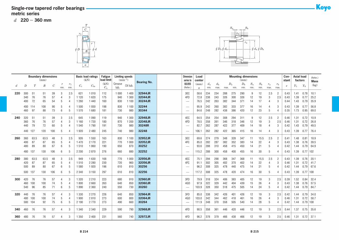
r
r1
u d
C
B
T
u D
a
u da u Dbu dbu Da
ra
Sa Sb
rb
metric seriesSingle-row tapered roller bearings
220 300 51 51 39 3 2.5 621 1 010 112 1 000 1 400 32944JR 3EC 58.6 234 234 288 275 290 9 12 2.5 2 0.43 1.41 0.78 10.1220 340 76 76 57 4 3 1 120 1 620 175 940 1 300 32044JR 4FD 72.8 238 243 326 300 326 12 19 3 2.5 0.43 1.39 0.77 25.2220 400 72 65 54 5 4 1 260 1 440 160 830 1 100 30244JR ⎯ 76.5 242 263 382 344 371 14 17 4 3 0.44 1.43 0.79 35.9
220 400 114 108 90 5 4 1 500 1 930 198 830 1 100 32244 ⎯ 95.9 242 260 382 333 377 16 14 4 3 0.43 1.39 0.77 56.8220 460 97 88 73 6 5 1 570 1 680 181 730 980 30344 ⎯ 84.6 248 282 438 386 420 12 23 5 4 0.35 1.73 0.95 69.0
240 320 51 51 39 3 2.5 645 1 090 119 940 1 300 32948JR 4EC 64.5 254 254 308 294 311 9 12 2.5 2 0.46 1.31 0.72 10.9240 360 76 76 57 4 3 1 160 1 720 180 870 1 200 32048JR 4FD 78.5 258 261 346 318 346 12 19 3 2.5 0.46 1.31 0.72 26.8240 440 79 72 60 5 4 1 540 1 790 191 730 980 30248R ⎯ 82.7 262 287 422 377 409 14 18 4 3 0.42 1.43 0.79 49.5
240 440 127 120 100 5 4 1 920 2 480 245 740 980 32248 ⎯ 106.1 262 282 422 365 415 16 14 4 3 0.43 1.39 0.77 76.4
260 360 63.5 63.5 48 3 2.5 926 1 550 163 830 1 100 32952JR 3EC 69.6 274 279 348 328 347 11 15.5 2.5 2 0.41 1.48 0.81 18.9260 400 87 87 65 5 4 1 470 2 170 221 770 1 000 32052JR 4FC 85.0 282 287 382 352 383 14 22 4 3 0.43 1.38 0.76 39.5260 480 89 80 67 6 5 1 510 1 860 190 650 870 30252 ⎯ 93.6 288 310 458 415 450 14 21 5 4 0.42 1.44 0.79 64.9
260 480 137 130 106 6 5 2 200 2 870 276 660 880 32252 ⎯ 115.2 288 300 458 400 455 16 30 5 4 0.43 1.39 0.77 102
280 380 63.5 63.5 48 3 2.5 949 1 630 168 770 1 000 32956JR 4EC 75.1 294 298 368 347 368 11 15.5 2.5 2 0.43 1.39 0.76 20.1280 420 87 87 65 5 4 1 510 2 280 230 720 960 32056JR 4FC 91.1 302 305 402 370 402 14 22 4 3 0.46 1.31 0.72 41.7280 500 89 80 67 6 5 1 580 1 920 196 610 810 30256 ⎯ 96.2 308 325 478 440 475 14 21 5 4 0.42 1.44 0.79 67.6
280 500 137 130 106 6 5 2 340 3 150 297 610 810 32256 ⎯ 117.2 308 325 478 420 474 16 30 5 4 0.43 1.39 0.77 108
300 420 76 76 57 4 3 1 320 2 210 223 680 910 32960JR 3FD 79.9 318 324 406 383 405 12 19 3 2.5 0.39 1.52 0.84 32.4300 460 100 100 74 5 4 1 800 2 660 263 640 850 32060JR 4GD 97.9 322 329 442 404 439 15 26 4 3 0.43 1.38 0.76 57.5300 540 96 85 71 6 5 1 890 2 360 240 550 730 30260 ⎯ 103.9 328 350 518 475 505 14 24 5 4 0.42 1.44 0.79 84.7
320 440 76 76 57 4 3 1 330 2 270 226 640 850 32964JR 3FD 85.0 338 342 426 401 426 12 19 3 2.5 0.42 1.44 0.79 34.0320 480 100 100 74 5 4 1 900 2 810 273 600 800 32064JR 4GD 103.0 342 344 462 418 461 16 26 4 3 0.46 1.31 0.72 58.7320 580 104 92 75 6 5 2 190 2 770 273 490 660 30264 ⎯ 111.9 348 370 558 505 540 14 28 5 4 0.42 1.44 0.79 108
340 460 76 76 57 4 3 1 340 2 340 229 590 790 32968JR 4FD 90.5 358 361 446 420 446 12 19 3 2.5 0.44 1.37 0.75 35.6
360 480 76 76 57 4 3 1 350 2 400 231 560 740 32972JR 4FD 96.2 378 379 466 438 466 12 19 3 2.5 0.46 1.31 0.72 37.1
Boundary dimensions Basic load ratings Fatigue Limiting speeds
Bearing No. 1)
Dimensionseries toISO355
Loadcenter(mm)
a
Mounting dimensions Con-stant
Axial load factors
(Refer.)
Mass(kg)
(mm) (kN) load limit (min−1) (mm)
d D T B Cr r1 Cr C0r
(kN) Greaselub.
Oil lub.da db Da Db Sa Sb ra rb e Y1 Y0min. min. Cu (Refer.) min. max. max. min. min. min. min. max. max.
[Note] 1) Please consult with JTEKT when using the bearings identified by suffix C. They are medium-tapered types es-pecially designed for special purposes.
B 214 B 215
d 220 ∼ 360 mm

r
r1
u d
C
B
T
u D
a
u dau Dbu dbu Da
ra
rb
inch seriesSingle-row tapered roller bearings
Boundary dimensions
Basic load ratings Fatigue
Limiting speeds Bearing No.
1)
Loadcenter
(mm)
a
Mounting dimensions Con-stant
Axial load factors
(Refer.)
Mass
(kg)(mm) (kN)
load limit
(min
−
1
) (mm)
d D T B Cr r
1
C
r
C
0r
(kN)
Grease lub.
Oil lub. Inner ring Outer ring
d
a
d
b
D
a
D
b
r
a
r
b
e Y
1
Y
0
Inner ring Outer ringmin. min.
C
u
max. max.
9.525
31.991 10.008 10.785 7.938 1.2 1.2 13.4 9.30 1.25 14 000 19 000
A2037 A2126
7.1 15.0 13.5 26.0 29.0 1.2 1.2 0.40 1.48 0.82 0.029 0.017
11.986
31.991 10.008 10.785 7.938 0.8 1.2 13.4 9.30 1.25 14 000 19 000
A2047 A2126
7.1 16.5 15.5 26.0 29.0 0.8 1.2 0.40 1.48 0.82 0.023 0.017
12.700
34.988 10.998 10.988 8.730 1.2 1.2 15.7 11.9 1.55 12 000 17 000
A4050 A4138
8.3 18.5 17.0 29.0 32.0 1.2 1.2 0.45 1.33 0.73 0.033 0.022
14.989
34.988 10.998 10.988 8.730 0.8 1.2 15.7 11.9 1.55 12 000 17 000
A4059 A4138
8.3 19.5 19.0 29.0 32.0 0.8 1.2 0.45 1.33 0.73 0.029 0.022
15.875
34.988 10.998 10.998 8.712 1.2 1.2 18.1 14.3 1.90 12 000 16 000
L21549 L21511
7.6 21.5 19.5 29.0 32.5 1.2 1.2 0.32 1.88 1.04 0.031 0.018
15.875
41.275 14.288 14.681 11.112 1.2 2.0 27.3 20.5 2.85 11 000 14 000
03062 03162
9.3 21.5 20.0 34.0 37.5 1.2 2.0 0.31 1.93 1.06 0.060 0.035
15.875
42.862 16.670 16.670 13.495 1.6 1.6 38.2 29.5 4.15 10 000 14 000
17580R 17520
10.9 23.0 21.0 36.5 39.0 1.6 1.6 0.33 1.81 1.00 0.078 0.048
15.875
49.225 19.845 21.539 14.288 0.8 1.2 47.2 37.7 5.40 8 900 12 000
09062 09195
10.6 22.0 21.5 42.0 44.5 0.8 1.2 0.27 2.26 1.24 0.139 0.065
15.875
53.975 22.225 21.839 15.875 0.8 2.4 52.6 41.2 5.65 8 400 11 000
21063 21212
16.6 29.0 26.5 43.0 50.0 0.8 2.4 0.59 1.02 0.56 0.163 0.097
16.000
47.000 21.000 21.000 16.000 1.0 2.0 45.4 37.7 5.05 9 800 13 000
HM81649 HM81610
15.0 27.5 23.0 37.5 43.0 1.0 2.0 0.55 1.10 0.60 0.111 0.080
17.462
39.878 13.843 14.605 10.668 1.2 1.2 31.8 26.0 3.60 11 000 14 000
LM11749R LM11710
8.6 23.0 21.5 34.0 37.0 1.2 1.2 0.29 2.10 1.15 0.058 0.028
19.050
45.237 15.494 16.637 12.065 1.2 1.2 36.8 30.1 4.25 9 400 13 000
LM11949 LM11910
10.0 25.0 23.5 39.5 41.5 1.2 1.2 0.30 2.00 1.10 0.081 0.044
19.050
49.225 19.845 21.539 14.288 1.2 1.2 47.2 37.7 5.40 8 900 12 000
09078 09195
10.6 25.5 24.0 42.0 44.5 1.2 1.2 0.27 2.26 1.24 0.124 0.065
19.050
49.225 21.209 19.050 17.462 1.2 1.6 47.2 37.7 5.40 8 900 12 000
09067 09196
13.8 25.5 24.0 41.5 44.5 1.2 1.6 0.27 2.26 1.24 0.114 0.084
20.000
50.005 13.495 14.260 9.525 1.6 1.0 33.3 28.8 4.05 7 900 11 000
07079 07196
10.8 27.5 26.0 44.5 47.0 1.6 1.0 0.40 1.49 0.82 0.104 0.034
20.638
49.225 19.845 19.845 15.875 1.6 1.6 45.5 37.7 5.35 8 600 12 000
12580 12520
12.7 28.5 26.0 42.5 45.5 1.6 1.6 0.32 1.86 1.02 0.116 0.067
21.430
50.005 17.526 18.288 13.970 1.2 1.2 48.8 40.7 5.80 8 500 11 000
M12649 M12610
11.1 27.5 25.5 44.0 46.0 1.2 1.2 0.28 2.16 1.19 0.119 0.058
21.987
45.974 15.494 16.637 12.065 1.2 1.2 37.5 34.6 4.85 8 900 12 000
LM12749 LM12711
10.0 27.5 26.0 40.0 42.5 1.2 1.2 0.31 1.96 1.08 0.078 0.043
22.225
50.005 17.526 18.288 13.970 1.2 1.2 48.8 40.7 5.80 8 500 11 000
M12648 M12610
11.1 28.5 26.5 44.0 46.0 1.2 1.2 0.28 2.16 1.19 0.115 0.058
22.225
52.388 19.368 20.168 14.288 1.6 1.6 45.9 37.9 5.45 8 000 11 000
1380 1328
11.6 29.5 29.5 45.0 48.5 1.6 1.6 0.29 2.05 1.13 0.132 0.066
22.225
53.975 19.368 20.168 14.288 1.6 1.6 45.9 37.9 5.45 8 000 11 000
1380 1329
11.6 29.5 29.5 46.0 49.0 1.6 1.6 0.29 2.05 1.13 0.137 0.082
[Note] 1) To the bearings with supplementary code "J" attached at the front of bearing number, tolerances shown in table7-8 on page A72 are applied.
[Remark] Inch series tapered roller bearings with bore diameter larger than 100 mm are shown in catalog "large size ball& roller bearings".
B 216 B 217
d
9.525
∼
(
22.225
)
mm

r
r1
u d
C
B
T
u D
a
u dau Dbu dbu Da
ra
rb
inch seriesSingle-row tapered roller bearings
22.225
56.896 19.368 19.837 15.875 1.2 1.2 50.0 43.1 6.20 7 600 10 000
1755 1729
12.5 29.0 27.5 49.0 51.0 1.2 1.2 0.31 1.95 1.07 0.150 0.100
22.225
57.150 22.225 22.225 17.462 0.8 1.6 65.8 55.7 8.05 7 600 10 000
1280 1220
15.3 29.5 29.0 49.0 52.0 0.8 1.6 0.35 1.73 0.95 0.189 0.105
22.225
66.421 23.812 25.433 19.050 1.6 1.2 83.8 75.2 11.2 6 500 8 700
2684 2631
13.9 31.5 29.0 58.0 60.0 1.6 1.2 0.25 2.36 1.30 0.295 0.163
22.606
47.000 15.500 15.500 12.000 1.6 1.0 35.0 32.8 4.45 8 700 12 000
LM72849 LM72810
12.3 30.0 28.0 40.5 44.0 1.6 1.0 0.47 1.27 0.70 0.076 0.047
23.812
50.292 14.224 14.732 10.668 1.6 1.2 39.1 37.0 5.15 7 800 10 000
L44640R L44610
10.8 30.5 28.5 44.5 47.0 1.6 1.2 0.37 1.60 0.88 0.099 0.034
23.812
56.896 19.368 19.837 15.875 0.8 1.2 50.0 43.1 6.20 7 600 10 000
1779 1729
12.5 29.5 28.5 49.0 51.0 0.8 1.2 0.31 1.95 1.07 0.141 0.100
24.981
50.005 13.495 14.260 9.525 1.6 1.0 33.3 28.8 4.05 7 900 11 000
07098 07196
10.8 31.0 29.0 44.5 47.0 1.6 1.0 0.40 1.49 0.82 0.084 0.034
24.981
62.000 16.002 16.566 14.288 1.6 1.6 47.4 40.6 5.80 6 700 8 900
17098 17244
12.7 33.0 30.5 54.0 57.0 1.6 1.6 0.38 1.57 0.86 0.162 0.090
25.000
50.005 13.495 14.260 9.525 1.6 1.0 33.3 28.8 4.05 7 900 11 000
07097 07196
10.8 31.0 29.0 44.5 47.0 1.6 1.0 0.40 1.49 0.82 0.085 0.035
25.400
50.005 13.495 14.260 9.525 1.0 1.0 33.3 28.8 4.05 7 900 11 000
07100 07196
10.8 30.5 29.5 44.5 47.0 1.0 1.0 0.40 1.49 0.82 0.084 0.035
25.400
50.005 13.495 14.260 9.525 1.6 1.0 33.3 28.8 4.05 7 900 11 000
07100S 07196
10.8 31.5 29.5 44.5 47.0 1.6 1.0 0.40 1.49 0.82 0.082 0.035
25.400
50.292 14.224 14.732 10.668 1.2 1.2 39.1 37.0 5.15 7 800 10 000
L44643R L44610
10.8 31.5 29.5 44.5 47.0 1.2 1.2 0.37 1.60 0.88 0.092 0.039
25.400
51.994 15.011 14.260 12.700 1.0 1.2 33.3 28.8 4.05 7 900 11 000
07100 07204
12.3 30.5 29.5 45.0 48.0 1.0 1.2 0.40 1.49 0.82 0.075 0.065
25.400
58.738 19.050 19.355 15.080 1.2 1.2 60.8 57.1 8.25 7 000 9 300
1986R 1932
13.1 32.5 30.5 52.0 54.0 1.2 1.2 0.33 1.82 1.00 0.179 0.088
25.400
59.530 23.368 23.114 18.288 0.8 1.6 63.0 57.1 7.95 7 200 9 600
M84249 M84210
18.2 36.0 32.5 49.5 56.0 0.8 1.6 0.55 1.10 0.60 0.194 0.128
25.400
61.912 19.050 20.638 14.288 0.8 2.0 55.7 50.7 7.30 6 400 8 600
15101 15243
13.2 32.5 31.5 55.0 58.0 0.8 2.0 0.35 1.71 0.94 0.215 0.080
25.400
62.000 19.050 20.638 14.288 3.6 1.2 55.7 50.7 7.30 6 400 8 600
15100 15245
13.2 38.0 31.5 55.0 58.0 3.6 1.2 0.35 1.71 0.94 0.215 0.081
25.400
63.500 19.050 20.638 14.288 0.8 1.2 55.7 50.7 7.30 6 400 8 600
15101 15250R
13.2 32.5 31.5 55.0 59.0 0.8 1.2 0.35 1.71 0.94 0.215 0.097
25.400
64.292 21.432 21.432 16.670 1.6 1.6 69.1 70.7 9.90 6 400 8 500
M86643R M86610
18.0 38.0 36.5 54.0 61.0 1.6 1.6 0.55 1.10 0.60 0.248 0.127
25.400
66.421 23.812 25.433 19.050 1.2 1.2 83.8 75.2 11.2 6 500 8 700
2687 2631
13.9 33.5 31.5 58.0 60.0 1.2 1.2 0.25 2.36 1.30 0.272 0.163
25.400
68.262 22.225 22.225 17.462 0.8 1.6 63.7 61.1 8.80 6 000 8 000
02473 02420
17.1 34.5 33.5 59.0 63.0 0.8 1.6 0.42 1.44 0.79 0.275 0.150
25.400
72.233 25.400 25.400 19.842 0.8 2.4 83.8 87.4 12.4 5 700 7 600
HM88630 HM88610
20.7 39.5 39.5 60.0 69.0 0.8 2.4 0.55 1.10 0.60 0.391 0.185
26.162
66.421 23.812 25.433 19.050 1.6 1.2 83.8 75.2 11.2 6 500 8 700
2682 2631
13.9 34.5 32.0 58.0 60.0 1.6 1.2 0.25 2.36 1.30 0.268 0.163
26.988
50.292 14.224 14.732 10.668 3.6 1.2 39.1 37.0 5.15 7 800 10 000
L44649R L44610
10.8 37.5 31.0 44.5 47.0 3.6 1.2 0.37 1.60 0.88 0.083 0.039
Boundary dimensions
Basic load ratings Fatigue
Limiting speeds Bearing No.
1)
Loadcenter
(mm)
a
Mounting dimensions Con-stant
Axial load factors
(Refer.)
Mass
(kg)(mm) (kN)
load limit
(min
−
1
) (mm)
d D T B Cr r
1
C
r
C
0r
(kN)
Grease lub.
Oil lub. Inner ring Outer ring
d
a
d
b
D
a
D
b
r
a
r
b
e Y
1
Y
0
Inner ring Outer ringmin. min.
C
u
max. max.
[Note] 1) To the bearings with supplementary code "J" attached at the front of bearing number, tolerances shown in table7-8 on page A72 are applied.
[Remark] Inch series tapered roller bearings with bore diameter larger than 100 mm are shown in catalog "large size ball& roller bearings".
B 218 B 219
d
(
22.225
)
∼
(
26.988
)
mm

r
r1
u d
C
B
T
u D
a
u dau Dbu dbu Da
ra
rb
inch seriesSingle-row tapered roller bearings
26.988
60.325 19.842 17.462 15.875 3.6 1.6 47.2 42.7 6.10 7 000 9 400
15580 15523
15.1 38.5 32.0 51.0 54.0 3.6 1.6 0.35 1.73 0.95 0.140 0.122
26.988
62.000 19.050 20.638 14.288 0.8 1.2 55.7 50.7 7.30 6 400 8 600
15106 15245
13.2 33.5 33.0 55.0 58.0 0.8 1.2 0.35 1.71 0.94 0.206 0.081
26.988
66.421 23.812 25.433 19.050 1.6 1.2 83.8 75.2 11.2 6 500 8 700
2688 2631
13.9 35.0 33.0 58.0 60.0 1.6 1.2 0.25 2.36 1.30 0.262 0.163
28.575
57.150 17.462 17.462 13.495 3.6 1.6 47.2 42.7 6.10 7 000 9 400
15590 15520
12.7 39.0 33.5 51.0 53.0 3.6 1.6 0.35 1.73 0.95 0.131 0.069
28.575
57.150 19.845 19.355 15.875 3.6 1.6 60.8 57.1 8.25 7 000 9 300
1988R 1922
13.9 39.5 33.5 51.0 53.5 3.6 1.6 0.33 1.82 1.00 0.151 0.076
28.575
62.000 19.050 20.638 14.288 3.6 1.2 55.7 50.7 7.30 6 400 8 600
15112 15245
13.2 40.0 34.0 55.0 58.0 3.6 1.2 0.35 1.71 0.94 0.193 0.081
28.575
62.000 19.050 20.638 14.288 0.8 1.2 55.7 50.7 7.30 6 400 8 600
15113 15245
13.2 34.5 34.0 55.0 58.0 0.8 1.2 0.35 1.71 0.94 0.195 0.081
28.575
64.292 21.432 21.432 16.670 1.6 1.6 69.1 70.7 9.90 6 400 8 500
M86647R M86610
18.0 40.0 38.0 54.0 61.0 1.6 1.6 0.55 1.10 0.60 0.225 0.127
28.575
66.421 23.812 25.433 19.050 1.2 1.2 83.8 75.2 11.2 6 500 8 700
2689 2631
13.9 36.0 34.0 58.0 60.0 1.2 1.2 0.25 2.36 1.30 0.249 0.165
28.575
68.262 22.225 22.225 17.462 0.8 1.6 63.7 61.1 8.80 6 000 8 000
02474 02420
17.1 36.5 36.0 59.0 63.0 0.8 1.6 0.42 1.44 0.79 0.252 0.150
28.575
72.000 19.000 18.923 15.875 1.6 1.6 59.4 49.6 7.25 5 900 7 800
26112 26283
15.3 37.0 35.0 62.0 65.0 1.6 1.6 0.36 1.67 0.92 0.217 0.163
28.575
72.626 24.608 24.257 17.462 4.8 1.6 77.3 60.5 8.75 6 100 8 100
41125 41286
20.7 48.0 36.5 61.0 68.0 4.8 1.6 0.60 1.00 0.55 0.292 0.177
28.575
72.626 24.608 24.257 17.462 1.6 1.6 77.3 60.5 8.75 6 100 8 100
41126 41286
20.7 41.5 36.5 61.0 68.0 1.6 1.6 0.60 1.00 0.55 0.295 0.177
28.575
72.626 30.162 29.997 23.812 3.6 3.2 98.6 89.3 13.3 5 800 7 700
3192 3120
20.3 42.5 37.0 61.0 67.0 3.6 3.2 0.33 1.80 0.99 0.401 0.222
28.575
72.626 30.162 29.997 23.812 1.2 3.2 98.6 89.3 13.3 5 800 7 700
3198 3120
20.3 39.0 37.0 61.0 67.0 1.2 3.2 0.33 1.80 0.99 0.410 0.222
28.575
73.025 22.225 22.225 17.462 0.8 3.2 68.8 65.7 9.55 5 500 7 400
02872 02820
18.4 37.5 37.0 62.0 68.0 0.8 3.2 0.45 1.32 0.73 0.319 0.158
29.000
50.292 14.224 14.732 10.668 3.6 1.2 36.3 37.2 5.15 7 600 10 000
L45449 L45410
10.9 39.5 33.0 44.5 48.0 3.6 1.2 0.37 1.62 0.89 0.079 0.036
29.367
66.421 23.812 25.433 19.050 3.6 1.2 83.8 75.2 11.2 6 500 8 700
2690 2631
13.9 41.0 35.0 58.0 60.0 3.6 1.2 0.25 2.36 1.30 0.242 0.165
29.987
62.000 16.002 16.566 14.288 1.6 1.6 47.4 40.6 5.80 6 700 8 900
17118 17244
12.7 37.0 34.5 54.0 57.0 1.6 1.6 0.38 1.57 0.86 0.135 0.090
29.987
62.000 19.050 20.638 14.288 1.2 1.2 55.7 50.7 7.30 6 400 8 600
15117 15245
13.2 36.5 35.0 55.0 58.0 1.2 1.2 0.35 1.71 0.94 0.184 0.081
30.000
69.012 19.845 19.583 15.875 3.6 1.2 57.7 55.0 7.95 5 900 7 800
14117A 14276
15.5 42.5 39.5 60.0 63.0 3.6 1.2 0.38 1.57 0.86 0.225 0.135
30.112
62.000 19.050 20.638 14.288 0.8 1.2 55.7 50.7 7.30 6 400 8 600
15116 15245
13.2 36.0 35.5 55.0 58.0 0.8 1.2 0.35 1.71 0.94 0.184 0.081
30.162
62.000 16.002 16.566 14.288 1.6 1.6 47.4 40.6 5.80 6 700 8 900
17119 17244
12.7 37.0 34.5 54.0 57.0 1.6 1.6 0.38 1.57 0.86 0.139 0.09130.162 64.292 21.432 21.432 16.670 1.6 1.6 69.1 70.7 9.90 6 400 8 500 M86649R M86610 18.0 41.0 38.0 54.0 61.0 1.6 1.6 0.55 1.10 0.60 0.213 0.127
Boundary dimensions Basic load ratings Fatigue Limiting speeds Bearing No. 1) Loadcenter(mm)
a
Mounting dimensions Con-stant
Axial load factors
(Refer.)
Mass (kg)(mm) (kN) load limit (min−1) (mm)
d D T B Cr r1 Cr C0r
(kN) Grease lub.
Oil lub. Inner ring Outer ring da db Da Dbra rb e Y1 Y0 Inner ring Outer ring
min. min. Cu max. max.
[Note] 1) To the bearings with supplementary code "J" attached at the front of bearing number, tolerances shown in table7-8 on page A72 are applied.
[Remark] Inch series tapered roller bearings with bore diameter larger than 100 mm are shown in catalog "large size ball& roller bearings".
B 220 B 221
d (26.988) ∼ (30.162) mm

r
r1
u d
C
B
T
u D
a
u dau Dbu dbu Da
ra
rb
inch seriesSingle-row tapered roller bearings
30.162 68.262 22.225 22.225 17.462 2.4 1.6 70.2 71.1 10.0 6 000 7 900 M88043 M88010 19.2 43.5 39.5 58.0 65.0 2.4 1.6 0.55 1.10 0.60 0.258 0.144
30.213 62.000 19.050 20.638 14.288 3.6 1.2 55.7 50.7 7.30 6 400 8 600 15118 15245 13.2 41.5 35.5 55.0 58.0 3.6 1.2 0.35 1.71 0.94 0.181 0.08130.213 62.000 19.050 20.638 14.288 1.6 1.2 55.7 50.7 7.30 6 400 8 600 15119 15245 13.2 37.5 35.5 55.0 58.0 1.6 1.2 0.35 1.71 0.94 0.183 0.08130.213 62.000 19.050 20.638 14.288 0.8 1.2 55.7 50.7 7.30 6 400 8 600 15120 15245 13.2 36.0 35.5 55.0 58.0 0.8 1.2 0.35 1.71 0.94 0.183 0.081
30.226 69.012 19.845 19.583 15.875 0.8 3.2 57.7 55.0 7.95 5 900 7 800 14116 14274 15.5 37.0 36.5 59.0 63.0 0.8 3.2 0.38 1.57 0.86 0.226 0.131
31.750 58.738 14.684 15.080 10.716 1.0 1.0 37.0 33.3 4.60 6 600 8 900 08125 08231 13.5 37.5 36.0 52.0 55.0 1.0 1.0 0.48 1.26 0.69 0.109 0.05631.750 59.131 15.875 16.764 11.811 SP 1.2 44.8 43.1 6.05 6 600 8 800 LM67048 LM67010 13.0 42.5 36.0 52.0 56.0 3.5 1.2 0.41 1.46 0.80 0.120 0.06231.750 62.000 18.161 19.050 14.288 SP 1.2 55.7 50.7 7.30 6 400 8 600 15123 15245 13.2 42.5 36.5 55.0 58.0 3.5 1.2 0.35 1.71 0.94 0.157 0.081
31.750 62.000 19.050 20.638 14.288 3.6 1.2 55.7 50.7 7.30 6 400 8 600 15125 15245 13.2 42.5 36.5 55.0 58.0 3.6 1.2 0.35 1.71 0.94 0.169 0.08131.750 62.000 19.050 20.638 14.288 0.8 1.2 55.7 50.7 7.30 6 400 8 600 15126 15245 13.2 37.0 36.5 55.0 58.0 0.8 1.2 0.35 1.71 0.94 0.171 0.08131.750 66.421 25.400 25.357 20.638 0.8 3.2 89.2 85.1 12.7 6 000 8 000 2580 2520 16.0 38.5 37.5 57.0 62.5 0.8 3.2 0.27 2.19 1.21 0.281 0.123
31.750 68.262 22.225 22.225 17.462 3.6 1.6 63.7 61.1 8.80 6 000 8 000 02475 02420 17.1 44.5 38.5 59.0 63.0 3.6 1.6 0.42 1.44 0.79 0.224 0.15031.750 68.262 22.225 22.225 17.462 0.8 1.6 63.7 61.1 8.80 6 000 8 000 02476 02420 17.1 39.0 38.5 59.0 63.0 0.8 1.6 0.42 1.44 0.79 0.226 0.15031.750 68.262 22.225 22.225 17.462 1.6 1.6 70.2 71.1 10.0 6 000 7 900 M88046 M88010 19.2 43.0 40.5 58.0 65.0 1.6 1.6 0.55 1.10 0.60 0.245 0.144
31.750 73.025 22.225 22.225 17.462 3.6 3.2 68.8 65.7 9.55 5 600 7 400 02875 02820 17.1 45.5 39.5 62.0 68.0 3.6 3.2 0.45 1.32 0.73 0.293 0.15831.750 73.025 22.225 22.225 17.462 0.8 3.2 68.8 65.7 9.55 5 500 7 400 02876 02820 17.1 40.0 39.5 62.0 68.0 0.8 3.2 0.45 1.32 0.73 0.293 0.15831.750 73.025 29.370 27.783 23.020 1.2 3.2 93.0 101 14.2 5 600 7 500 HM88542 HM88510 23.4 45.5 42.5 59.0 70.0 1.2 3.2 0.55 1.10 0.60 0.377 0.238
31.750 73.812 29.370 27.783 23.020 1.2 3.2 93.0 101 14.2 5 600 7 500 HM88542 HM88512 23.4 45.5 42.5 59.0 70.0 1.2 3.2 0.55 1.10 0.60 0.377 0.254
33.338 68.262 22.225 22.225 17.462 0.8 1.6 70.2 71.1 10.0 6 000 7 900 M88048 M88010 19.2 42.5 41.0 58.0 65.0 0.8 1.6 0.55 1.10 0.60 0.231 0.14433.338 72.000 19.000 18.923 15.875 3.6 1.6 69.8 60.0 8.85 5 900 7 800 26131 26283 14.3 44.5 38.5 62.0 65.0 3.6 1.6 0.36 1.67 0.92 0.200 0.16333.338 73.025 29.370 27.783 23.020 0.8 3.2 93.0 101 14.2 5 600 7 500 HM88547 HM88510 23.4 45.5 42.6 59.0 70.0 0.8 3.2 0.55 1.10 0.60 0.360 0.238
33.338 76.200 29.370 28.575 23.020 0.8 3.2 99.5 107 15.2 5 400 7 200 HM89443 HM89410 23.9 46.5 44.6 62.0 73.0 0.8 3.2 0.55 1.10 0.60 0.415 0.254
34.925 65.088 18.034 18.288 13.970 SP 1.2 60.0 58.5 8.40 6 000 8 000 LM48548 LM48510 14.3 46.0 40.0 58.0 61.0 3.5 1.2 0.38 1.59 0.88 0.164 0.08634.925 69.012 26.982 26.721 15.875 0.8 1.2 57.7 55.0 7.95 5 900 7 800 14136A 14276 22.6 40.0 38.0 60.0 63.0 0.8 1.2 0.38 1.57 0.86 0.254 0.13334.925 72.233 25.400 25.400 19.842 2.4 2.4 83.8 87.4 12.4 5 700 7 600 HM88649 HM88610 20.7 48.5 42.5 60.0 69.0 2.4 2.4 0.55 1.10 0.60 0.301 0.185
Boundary dimensions Basic load ratings Fatigue Limiting speeds Bearing No. 1) Loadcenter(mm)
a
Mounting dimensions Con-stant
Axial load factors
(Refer.)
Mass (kg)(mm) (kN) load limit (min−1) (mm)
d D T B Cr r1 Cr C0r
(kN) Grease lub.
Oil lub. Inner ring Outer ring da db Da Dbra rb e Y1 Y0 Inner ring Outer ring
min. min. Cu max. max.
[Note] 1) To the bearings with supplementary code "J" attached at the front of bearing number, tolerances shown in table7-8 on page A72 are applied.
[Remark] Inch series tapered roller bearings with bore diameter larger than 100 mm are shown in catalog "large size ball& roller bearings".
B 222 B 223
d (30.162) ∼ (34.925) mm
[Note] 1) SP indicates the specially chamfered from.
1)

r
r1
u d
C
B
T
u D
a
u dau Dbu dbu Da
ra
rb
inch seriesSingle-row tapered roller bearings
34.925 72.238 20.638 20.638 15.875 3.6 1.2 62.3 61.3 8.90 5 600 7 400 16137 16284 16.6 46.5 40.5 63.0 67.0 3.6 1.2 0.40 1.49 0.82 0.236 0.14434.925 73.025 22.225 22.225 17.462 3.6 3.2 68.8 65.7 9.55 5 500 7 400 02877 02820 18.4 48.5 42.0 62.0 68.0 3.6 3.2 0.45 1.32 0.73 0.262 0.15834.925 73.025 22.225 22.225 17.462 0.8 3.2 68.8 65.7 9.55 5 500 7 400 02878 02820 18.4 42.5 42.0 62.0 68.0 0.8 3.2 0.45 1.32 0.73 0.265 0.158
34.925 73.025 23.812 24.608 19.050 1.6 0.8 90.1 87.3 13.1 5 600 7 400 25877R 25821 15.8 43.0 40.5 65.0 68.0 1.6 0.8 0.29 2.07 1.14 0.310 0.16534.925 73.025 26.988 26.975 22.225 3.6 1.6 97.2 94.1 13.9 5 700 7 600 23690 23620 18.8 49.0 42.0 64.0 68.0 3.6 1.6 0.37 1.62 0.89 0.326 0.21234.925 76.200 20.638 20.940 15.507 1.6 1.2 71.6 65.9 9.70 5 300 7 000 28137 28300 16.5 43.5 41.0 68.0 71.0 1.6 1.2 0.40 1.49 0.82 0.315 0.137
34.925 76.200 23.812 25.654 19.050 3.6 3.2 92.6 92.2 13.8 5 400 7 200 2796R 2720 15.9 47.5 41.0 66.0 70.0 3.6 3.2 0.30 1.98 1.09 0.344 0.18534.925 76.200 29.370 28.575 23.812 1.6 3.2 101 97.4 14.4 5 400 7 200 31594 31520 21.6 46.0 43.5 64.0 72.0 1.6 3.2 0.40 1.49 0.82 0.388 0.23234.925 79.375 29.370 29.771 23.812 3.6 3.2 109 105 15.7 5 200 6 900 3478 3420 20.8 50.0 43.5 67.0 74.0 3.6 3.2 0.37 1.64 0.90 0.462 0.256
34.925 87.312 30.162 30.886 23.812 3.6 3.2 120 120 18.2 4 600 6 200 3581R 3525 20.5 48.0 45.5 75.0 81.0 3.6 3.2 0.31 1.96 1.08 0.622 0.30034.925 95.250 27.783 29.901 22.225 0.8 2.4 129 122 18.8 4 500 5 900 449 432 18.4 44.0 43.5 83.0 87.0 0.8 2.4 0.28 2.11 1.16 0.686 0.384
34.980 59.131 15.875 16.764 11.938 SP 1.2 44.9 48.5 6.85 6 400 8 500 L68149 L68110 13.2 45.5 39.0 53.0 56.0 3.5 1.2 0.42 1.44 0.79 0.112 0.05634.980 59.975 15.875 16.764 11.938 SP 1.2 44.9 48.5 6.85 6 400 8 500 L68149 L68111 13.2 45.5 39.0 53.0 56.0 3.5 1.2 0.42 1.44 0.79 0.112 0.063
35.000 79.375 23.812 25.400 19.050 0.8 0.8 101 105 15.8 5 000 6 700 26883R 26822 16.4 42.5 42.0 71.0 74.0 0.8 0.8 0.32 1.88 1.04 0.414 0.18635.000 80.000 21.000 22.403 17.826 0.8 1.2 85.0 74.8 11.4 4 900 6 600 339 332 15.1 42.5 41.5 73.0 75.0 0.8 1.2 0.27 2.20 1.21 0.385 0.144
35.717 72.233 25.400 25.400 19.842 3.6 2.4 83.8 87.4 12.4 5 700 7 600 HM88648 HM88610 20.7 52.0 42.5 60.0 69.0 3.6 2.4 0.55 1.10 0.60 0.291 0.185
36.487 73.025 23.812 24.608 19.050 1.6 0.8 90.1 87.3 13.1 5 600 7 400 25880R 25821 15.8 44.0 42.0 65.0 68.0 1.6 0.8 0.29 2.07 1.14 0.294 0.16536.487 73.025 23.812 25.654 19.050 3.6 0.8 92.6 92.2 13.8 5 400 7 200 2794R 2735X 15.9 49.0 42.5 66.0 69.0 3.6 0.8 0.30 1.98 1.09 0.344 0.134
36.512 76.200 29.370 28.575 23.020 3.6 0.8 99.5 107 15.2 5 400 7 200 HM89449 HM89411 23.9 54.0 44.5 65.0 73.0 3.6 0.8 0.55 1.10 0.60 0.386 0.25836.512 79.375 23.812 25.400 19.050 0.8 0.8 101 105 15.8 5 000 6 700 26877R 26822 16.4 44.0 43.0 71.0 74.0 0.8 0.8 0.32 1.88 1.04 0.404 0.18636.512 79.375 29.370 29.771 23.812 0.8 3.2 109 105 15.7 5 200 6 900 3479 3420 20.8 45.5 44.5 67.0 74.0 0.8 3.2 0.37 1.64 0.90 0.429 0.259
36.512 85.725 30.162 30.162 23.812 0.8 3.2 135 136 20.3 4 800 6 400 3878 3820 22.9 48.0 47.0 73.0 81.0 0.8 3.2 0.40 1.49 0.82 0.605 0.285
38.000 63.000 17.000 17.000 13.500 SP SP 54.7 58.2 8.25 6 000 8 000 JL69349 JL69310 14.6 49.0 41.0 60.0 56.5 3.5 1.2 0.42 1.44 0.79 0.128 0.070
38.100 63.500 12.700 11.908 9.525 1.6 0.8 32.1 33.1 4.60 5 800 7 700 13889 13830 11.9 45.0 42.5 59.0 60.0 1.6 0.8 0.35 1.73 0.95 0.104 0.045
Boundary dimensions Basic load ratings Fatigue Limiting speeds Bearing No. 1) Loadcenter(mm)
a
Mounting dimensions Con-stant
Axial load factors
(Refer.)
Mass (kg)(mm) (kN) load limit (min−1) (mm)
d D T B Cr r1 Cr C0r
(kN) Grease lub.
Oil lub. Inner ring Outer ring da db Da Dbra rb e Y1 Y0 Inner ring Outer ring
min. min. Cu max. max.
[Note] 1) To the bearings with supplementary code "J" attached at the front of bearing number, tolerances shown in table7-8 on page A72 are applied.
[Remark] Inch series tapered roller bearings with bore diameter larger than 100 mm are shown in catalog "large size ball& roller bearings".
B 224 B 225
d (34.925) ∼ (38.100) mm
[Notes] 1) SP indicates the specially chamfered from.2) To the bearings with supplementary code "J" attached at the front of bearing number, tolerances shown in
table 7-8 on page A72 are applied.
2)
1)1)
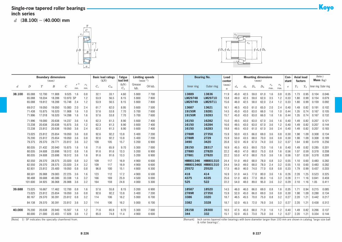
r
r1
u d
C
B
T
u D
a
u dau Dbu dbu Da
ra
rb
inch seriesSingle-row tapered roller bearings
38.100 65.088 12.700 11.908 9.525 1.6 0.8 32.1 33.1 4.60 5 800 7 700 13889 13836 11.9 45.0 42.5 59.0 61.0 1.6 0.8 0.35 1.73 0.95 0.104 0.04638.100 65.088 18.034 18.288 13.970 SP 1.2 53.9 56.5 8.15 5 800 7 800 LM29748 LM29710 13.8 49.0 42.5 59.0 62.0 3.5 1.2 0.33 1.80 0.99 0.154 0.07938.100 65.088 19.812 18.288 15.748 2.4 1.2 53.9 56.5 8.15 5 800 7 800 LM29749 LM29711 15.6 46.0 42.5 58.0 62.0 2.4 1.2 0.33 1.80 0.99 0.159 0.092
38.100 69.012 19.050 19.050 15.083 2.0 2.4 61.7 62.0 8.95 5 600 7 500 13687 13621 16.1 46.5 43.0 61.0 65.0 2.0 2.4 0.40 1.49 0.82 0.191 0.10238.100 71.438 15.875 16.520 11.908 1.6 1.0 57.6 53.8 7.70 5 700 7 600 19150R 19281 14.5 45.0 43.0 63.0 66.0 1.6 1.0 0.44 1.35 0.74 0.167 0.10538.100 71.996 17.018 16.520 14.288 1.6 1.6 57.6 53.8 7.70 5 700 7 600 19150R 19283 15.7 45.0 43.0 63.0 66.0 1.6 1.6 0.44 1.35 0.74 0.167 0.132
38.100 71.996 19.000 20.638 14.237 3.6 1.6 62.3 61.3 8.90 5 600 7 400 16150 16282 15.0 49.5 43.0 63.0 67.0 3.6 1.6 0.40 1.49 0.82 0.207 0.12138.100 72.238 20.638 20.638 15.875 3.6 1.2 62.3 61.3 8.90 5 600 7 400 16150 16284 16.6 49.5 43.0 63.0 67.0 3.6 1.2 0.40 1.49 0.82 0.207 0.14438.100 72.238 23.812 20.638 19.050 3.6 2.4 62.3 61.3 8.90 5 600 7 400 16150 16283 19.8 49.5 43.0 61.0 67.0 3.6 2.4 0.40 1.49 0.82 0.207 0.183
38.100 73.025 23.812 25.654 19.050 3.6 0.8 92.6 92.2 13.8 5 400 7 200 2788R 2735X 15.9 50.0 43.5 66.0 69.0 3.6 0.8 0.30 1.98 1.09 0.308 0.13438.100 76.200 23.812 25.654 19.050 3.6 0.8 92.6 92.2 13.8 5 400 7 200 2788R 2729 15.9 50.0 43.5 68.0 70.0 3.6 0.8 0.30 1.98 1.09 0.308 0.18938.100 79.375 29.370 29.771 23.812 3.6 3.2 109 105 15.7 5 200 6 900 3490 3420 20.8 52.0 45.9 67.0 74.0 3.6 3.2 0.37 1.64 0.90 0.419 0.256
38.100 80.035 21.432 20.940 15.875 1.6 1.6 71.6 65.9 9.70 5 300 7 000 28150 28317 16.9 45.5 43.5 69.0 73.0 1.6 1.6 0.40 1.49 0.82 0.285 0.20138.100 80.035 24.608 23.698 18.512 0.8 1.6 91.6 91.6 13.3 5 200 6 900 27880 27820 22.2 48.0 47.0 68.0 75.0 0.8 1.6 0.56 1.07 0.59 0.378 0.20838.100 80.035 24.608 23.698 18.512 3.6 1.6 91.6 91.6 13.3 5 200 6 900 27881 27820 22.2 53.0 47.0 68.0 75.0 3.6 1.6 0.56 1.07 0.59 0.378 0.208
38.100 82.550 29.370 28.575 23.020 0.8 3.2 109 117 16.9 4 900 6 600 HM801346 HM801310 24.4 51.0 49.0 68.0 78.0 0.8 3.2 0.55 1.10 0.60 0.483 0.28238.100 82.550 29.370 28.575 23.020 2.4 3.2 109 117 16.9 4 900 6 600 HM801346X HM801310 24.4 54.0 49.0 68.0 78.0 2.4 3.2 0.55 1.10 0.60 0.483 0.28238.100 82.931 23.812 25.400 19.050 0.8 0.8 96.8 100 15.1 4 800 6 300 25572 25520 17.5 46.0 46.0 74.0 77.0 0.8 0.8 0.33 1.79 0.99 0.437 0.203
38.100 88.501 26.988 29.083 22.225 3.6 1.6 123 112 17.2 4 900 6 500 418 414 16.9 51.0 44.5 77.0 80.0 3.6 1.6 0.26 2.28 1.25 0.523 0.32538.100 90.488 39.688 40.386 33.338 1.6 3.2 166 169 25.9 4 500 6 000 4375 4335 25.6 51.0 48.5 77.0 85.0 1.6 3.2 0.28 2.11 1.16 0.841 0.45938.100 101.600 34.925 36.068 26.988 3.6 3.2 164 159 24.8 4 000 5 300 525 522 22.2 54.0 48.0 89.0 95.0 3.6 3.2 0.29 2.10 1.16 1.05 0.411
39.688 73.025 16.667 17.462 12.700 0.8 1.6 57.6 55.8 8.15 5 200 6 900 18587 18520 14.5 46.0 46.0 66.0 69.0 0.8 1.6 0.35 1.71 0.94 0.215 0.08539.688 73.025 23.812 25.654 19.050 3.6 0.8 92.6 92.2 13.8 5 400 7 200 2789R 2735X 15.9 52.0 45.0 66.0 69.0 3.6 0.8 0.30 1.98 1.09 0.288 0.13439.688 80.167 29.370 30.391 23.812 0.8 3.2 114 106 16.2 5 000 6 700 3386 3320 18.7 46.5 45.5 70.0 75.0 0.8 3.2 0.27 2.20 1.21 0.442 0.217
39.688 84.138 29.370 30.391 23.812 3.6 3.2 114 106 16.2 5 000 6 700 3382 3328 18.7 52.0 45.5 72.0 76.0 3.6 3.2 0.27 2.20 1.21 0.438 0.312
40.000 76.200 20.638 20.940 15.507 1.6 1.2 71.6 65.9 9.70 5 300 7 000 28158 28300 16.5 47.5 45.0 68.0 71.0 1.6 1.2 0.40 1.49 0.82 0.266 0.13740.000 80.000 21.000 22.403 17.826 3.6 1.2 85.0 74.8 11.4 4 900 6 600 344 332 15.1 52.0 45.5 73.0 75.0 3.6 1.2 0.27 2.20 1.21 0.334 0.144
Boundary dimensions Basic load ratings Fatigue Limiting speeds Bearing No. 1) Loadcenter(mm)
a
Mounting dimensions Con-stant
Axial load factors
(Refer.)
Mass (kg)(mm) (kN) load limit (min−1) (mm)
d D T B Cr r1 Cr C0r
(kN) Grease lub.
Oil lub. Inner ring Outer ring da db Da Dbra rb e Y1 Y0 Inner ring Outer ring
min. min. Cu max. max.
[Note] 1) To the bearings with supplementary code "J" attached at the front of bearing number, tolerances shown in table7-8 on page A72 are applied.
[Remark] Inch series tapered roller bearings with bore diameter larger than 100 mm are shown in catalog "large size ball& roller bearings".
B 226 B 227
d (38.100) ∼ (40.000) mm
[Note] 1) SP indicates the specially chamfered from.
1)

r
r1
u d
C
B
T
u D
a
u dau Dbu dbu Da
ra
rb
inch seriesSingle-row tapered roller bearings
40.000 80.000 21.000 22.403 17.826 0.8 1.2 85.0 74.8 11.4 4 900 6 600 344A 332 15.1 46.0 45.5 73.0 75.0 0.8 1.2 0.27 2.20 1.21 0.334 0.14440.000 85.000 20.638 21.692 17.462 0.8 1.2 89.6 81.7 12.4 4 600 6 200 350A 354A 15.5 47.5 46.5 77.0 80.0 0.8 1.2 0.31 1.96 1.08 0.416 0.16240.000 88.501 26.988 29.083 22.225 3.6 1.6 123 112 17.2 4 900 6 500 420 414 16.9 52.0 46.0 77.0 80.0 3.6 1.6 0.26 2.28 1.25 0.465 0.325
40.000 107.950 36.512 36.957 28.575 3.6 3.2 172 172 26.8 3 800 5 100 543 532X 23.9 57.0 50.0 94.0 100.0 3.6 3.2 0.30 2.03 1.11 1.17 0.570
40.483 82.550 29.370 28.575 23.020 3.6 3.2 109 117 16.9 4 900 6 600 HM801349 HM801310 24.4 58.0 49.0 68.0 78.0 3.6 3.2 0.55 1.10 0.60 0.450 0.282
41.275 73.025 16.667 17.462 12.700 3.6 1.6 57.6 55.8 8.15 5 200 6 900 18590 18520 14.5 53.0 46.0 66.0 69.0 3.6 1.6 0.35 1.71 0.94 0.199 0.08541.275 73.431 19.558 19.812 14.732 3.6 0.8 72.5 73.0 10.6 5 200 7 000 LM501349 LM501310 16.1 53.0 46.5 67.0 70.0 3.6 0.8 0.40 1.50 0.83 0.227 0.10741.275 73.431 21.430 19.812 16.604 3.6 0.8 72.5 73.0 10.6 5 200 7 000 LM501349 LM501314 18.0 53.0 46.5 66.0 70.0 3.6 0.8 0.40 1.50 0.83 0.227 0.126
41.275 73.431 23.012 19.812 18.186 3.6 2.4 72.5 73.0 10.6 5 200 7 000 LM501349 LM501311 16.1 53.0 46.5 64.0 70.0 3.6 2.4 0.40 1.50 0.83 0.227 0.14041.275 76.200 18.009 17.384 14.288 1.6 1.6 64.7 63.3 9.15 5 200 6 900 11162R 11300 17.5 49.0 46.5 67.0 72.0 1.6 1.6 0.49 1.23 0.68 0.221 0.12741.275 76.200 22.225 23.020 17.462 3.6 0.8 82.9 83.3 12.3 5 200 6 900 24780R 24720 17.4 54.0 47.0 68.0 72.0 3.6 0.8 0.39 1.53 0.84 0.275 0.148
41.275 80.000 21.000 22.403 17.826 0.8 1.2 85.0 74.8 11.4 4 900 6 600 336 332 15.1 47.0 46.0 73.0 75.0 0.8 1.2 0.27 2.20 1.21 0.325 0.14441.275 80.000 21.000 22.403 17.826 3.6 1.2 85.0 74.8 11.4 4 900 6 600 342 332 15.1 53.0 46.0 73.0 75.0 3.6 1.2 0.27 2.20 1.21 0.317 0.14441.275 82.550 26.543 25.654 20.193 3.6 3.2 105 105 15.4 4 900 6 500 M802048 M802011 23.3 57.0 50.6 70.0 79.0 3.6 3.2 0.55 1.10 0.60 0.403 0.227
41.275 85.725 30.162 30.162 23.812 3.6 1.2 135 136 20.3 4 800 6 400 3877 3821 22.9 57.0 50.3 75.0 81.0 3.6 1.2 0.40 1.49 0.82 0.506 0.32441.275 87.312 30.162 30.886 23.812 0.8 3.2 120 120 18.2 4 600 6 200 3576R 3525 20.5 49.0 48.0 75.0 81.0 0.8 3.2 0.31 1.96 1.08 0.533 0.30041.275 88.501 26.988 29.083 22.225 3.6 1.6 123 112 17.2 4 900 6 500 419 414 16.9 54.0 47.0 77.0 80.0 3.6 1.6 0.26 2.28 1.25 0.441 0.325
41.275 88.900 20.638 22.225 16.513 3.6 1.2 92.9 87.3 13.3 4 400 5 800 365A 362A 16.1 55.0 48.5 81.0 84.0 3.6 1.2 0.32 1.88 1.03 0.458 0.16441.275 88.900 30.162 29.370 23.020 0.8 3.2 124 125 18.5 4 600 6 100 HM803145 HM803110 26.1 54.0 53.0 74.0 85.0 0.8 3.2 0.55 1.10 0.60 0.577 0.31841.275 88.900 30.162 29.370 23.020 3.6 3.2 124 125 18.5 4 600 6 100 HM803146 HM803110 26.1 60.0 53.0 74.0 85.0 3.6 3.2 0.55 1.10 0.60 0.574 0.318
41.275 90.488 39.688 40.386 33.338 3.6 3.2 166 169 25.9 4 500 6 000 4388 4335 25.6 57.0 51.0 77.0 85.0 3.6 3.2 0.28 2.11 1.16 0.775 0.45441.275 93.662 31.750 31.750 26.195 0.8 3.2 132 134 20.2 4 400 5 800 46162 46368 24.0 52.0 51.0 79.0 87.0 0.8 3.2 0.40 1.49 0.82 0.695 0.40341.275 95.250 30.162 29.370 23.020 3.6 3.2 130 140 20.7 3 300 4 400 HM804840 HM804810 26.5 61.0 54.0 81.0 91.0 3.6 3.2 0.55 1.10 0.60 0.719 0.351
41.275 101.600 34.925 36.068 26.988 3.6 3.2 164 159 24.8 4 000 5 300 526 522 22.2 57.0 50.0 89.0 95.0 3.6 3.2 0.29 2.10 1.16 1.02 0.41141.275 104.775 36.512 36.512 28.575 1.6 3.2 176 195 29.3 3 800 5 100 HM807035 HM807010 29.3 60.0 57.0 89.0 100.0 1.6 3.2 0.49 1.23 0.68 1.19 0.497
42.070 90.488 39.688 40.386 33.338 3.6 3.2 166 169 25.9 4 500 6 000 4395 4335 25.6 58.0 51.0 77.0 85.0 3.6 3.2 0.28 2.11 1.16 0.751 0.459
Boundary dimensions Basic load ratings Fatigue Limiting speeds Bearing No. 1) Loadcenter(mm)
a
Mounting dimensions Con-stant
Axial load factors
(Refer.)
Mass (kg)(mm) (kN) load limit (min−1) (mm)
d D T B Cr r1 Cr C0r
(kN) Grease lub.
Oil lub. Inner ring Outer ring da db Da Dbra rb e Y1 Y0 Inner ring Outer ring
min. min. Cu max. max.
[Note] 1) To the bearings with supplementary code "J" attached at the front of bearing number, tolerances shown in table7-8 on page A72 are applied.
[Remark] Inch series tapered roller bearings with bore diameter larger than 100 mm are shown in catalog "large size ball& roller bearings".
B 228 B 229
d (40.000) ∼ 42.070 mm

r
r1
u d
C
B
T
u D
a
u dau Dbu dbu Da
ra
rb
inch seriesSingle-row tapered roller bearings
42.862 76.992 17.463 17.145 11.908 1.6 1.6 60.8 62.2 8.95 5 000 6 600 12168 12303 17.5 51.0 48.5 68.0 73.0 1.6 1.6 0.51 1.19 0.65 0.220 0.097
42.875 79.375 23.812 25.400 19.050 3.6 0.8 101 105 15.8 5 000 6 700 26884R 26822 16.1 55.0 48.5 71.0 74.0 3.6 0.8 0.32 1.88 1.04 0.314 0.18642.875 82.931 23.812 25.400 19.050 3.6 0.8 96.8 100 15.1 4 800 6 300 25577 25520 17.5 55.0 49.0 74.0 77.0 3.6 0.8 0.33 1.79 0.99 0.382 0.200
44.450 73.025 18.258 18.258 15.083 1.6 1.6 59.4 65.5 9.50 5 100 6 800 L102849 L102810 14.6 51.0 49.0 66.0 69.0 1.6 1.6 0.32 1.88 1.04 0.183 0.10244.450 76.992 17.463 17.145 11.908 1.6 1.6 60.8 62.2 8.95 5 000 6 600 12175 12303 17.5 52.0 49.5 68.0 73.0 1.6 1.6 0.51 1.19 0.65 0.206 0.09744.450 79.375 17.462 17.462 13.495 2.8 1.6 59.2 59.1 8.65 4 800 6 400 18685 18620 16.0 54.0 49.5 71.0 74.0 2.8 1.6 0.37 1.60 0.88 0.214 0.126
44.450 82.931 23.812 25.400 19.050 5.2 0.8 96.8 100 15.1 4 800 6 300 25582 25520 17.5 59.0 51.0 74.0 77.0 5.2 0.8 0.33 1.79 0.99 0.361 0.20044.450 84.138 30.162 30.886 23.812 3.6 3.2 120 120 18.2 4 600 6 200 3578R 3520 20.5 57.0 51.0 74.0 79.5 3.6 3.2 0.31 1.96 1.08 0.479 0.22144.450 85.000 20.638 21.692 17.462 2.4 1.2 89.6 81.7 12.4 4 600 6 200 355 354A 15.5 54.0 50.0 77.0 80.0 2.4 1.2 0.31 1.96 1.08 0.344 0.160
44.450 85.000 20.638 21.692 17.462 0.8 1.2 89.6 81.7 12.4 4 600 6 200 355A 354A 15.5 51.0 50.0 77.0 80.0 0.8 1.2 0.31 1.96 1.08 0.344 0.16044.450 88.900 30.162 29.370 23.020 3.6 3.2 124 125 18.5 4 600 6 100 HM803149 HM803110 26.1 62.0 53.4 74.0 85.0 3.6 3.2 0.55 1.10 0.60 0.525 0.31844.450 93.662 31.750 31.750 25.400 3.6 3.2 131 123 18.8 4 400 5 900 49175 49368 22.9 59.0 53.0 82.0 87.0 3.6 3.2 0.36 1.67 0.92 0.645 0.371
44.450 93.662 31.750 31.750 26.195 0.8 3.2 132 134 20.2 4 400 5 800 46175 46368 24.0 55.0 54.0 79.0 87.0 0.8 3.2 0.40 1.49 0.82 0.609 0.40344.450 93.662 31.750 31.750 26.195 3.6 3.2 132 134 20.2 4 400 5 800 46176 46368 24.0 60.0 54.0 79.0 87.0 3.6 3.2 0.40 1.49 0.82 0.609 0.40344.450 95.250 27.783 28.575 22.225 0.8 2.4 135 141 21.6 4 100 5 400 33885 33821 20.4 53.0 53.0 85.0 90.0 0.8 2.4 0.33 1.82 1.00 0.714 0.264
44.450 95.250 27.783 29.901 22.225 3.6 0.8 129 122 18.8 4 500 5 900 438 432A 18.4 57.0 51.0 84.0 87.0 3.6 0.8 0.28 2.11 1.16 0.555 0.37544.450 95.250 30.162 29.370 23.020 0.8 2.4 130 140 20.7 3 300 4 400 HM804842 HM804810 26.5 57.0 57.0 81.0 91.0 0.8 2.4 0.55 1.10 0.60 0.673 0.35144.450 95.250 30.162 29.370 23.020 3.6 2.4 130 140 20.7 3 300 4 400 HM804843 HM804810 26.5 63.0 57.0 81.0 91.0 3.6 2.4 0.55 1.10 0.60 0.670 0.351
44.450 98.425 30.162 31.750 25.400 0.8 3.2 143 143 21.9 3 900 5 200 49576 49520 24.1 55.0 54.0 88.0 96.0 0.8 3.2 0.40 1.50 0.82 0.856 0.38444.450 101.600 34.925 36.068 26.988 3.6 3.2 164 159 24.8 4 000 5 300 527 522 22.2 59.0 53.0 89.0 95.0 3.6 3.2 0.29 2.10 1.16 0.939 0.41144.450 104.775 36.512 36.512 28.575 3.6 3.2 176 195 29.3 3 800 5 100 HM807040 HM807010 29.3 66.0 59.0 89.0 100.0 3.6 3.2 0.49 1.23 0.68 1.13 0.497
44.450 111.125 38.100 36.957 30.162 3.6 3.2 172 172 26.8 3 800 5 100 535 532A 23.9 60.0 54.0 95.0 100.0 3.6 3.2 0.30 2.03 1.11 1.09 0.74644.450 120.650 41.275 41.275 31.750 3.6 3.2 218 217 34.0 3 500 4 600 615 612 27.3 62.0 56.0 105.0 110.0 3.6 3.2 0.31 1.91 1.05 1.48 0.853
44.983 93.264 30.162 30.302 23.812 3.6 3.2 129 137 20.9 4 200 5 500 3776 3720 22.2 59.0 53.0 82.0 88.0 3.6 3.2 0.34 1.77 0.97 0.650 0.288
45.000 85.000 20.638 21.692 17.462 1.6 1.2 89.6 81.7 12.4 4 600 6 200 358 354A 15.5 52.5 50.0 77.0 80.0 1.6 1.2 0.31 1.96 1.08 0.338 0.162
Boundary dimensions Basic load ratings Fatigue Limiting speeds Bearing No. 1) Loadcenter(mm)
a
Mounting dimensions Con-stant
Axial load factors
(Refer.)
Mass (kg)(mm) (kN) load limit (min−1) (mm)
d D T B Cr r1 Cr C0r
(kN) Grease lub.
Oil lub. Inner ring Outer ring da db Da Dbra rb e Y1 Y0 Inner ring Outer ring
min. min. Cu max. max.
[Note] 1) To the bearings with supplementary code "J" attached at the front of bearing number, tolerances shown in table7-8 on page A72 are applied.
[Remark] Inch series tapered roller bearings with bore diameter larger than 100 mm are shown in catalog "large size ball& roller bearings".
B 230 B 231
d 42.862 ∼ 45.000 mm

r
r1
u d
C
B
T
u D
a
u dau Dbu dbu Da
ra
rb
inch seriesSingle-row tapered roller bearings
45.242 73.431 19.558 19.812 15.748 3.6 0.8 70.0 78.1 11.4 5 100 6 700 LM102949 LM102910 14.7 56.0 50.0 68.0 70.0 3.6 0.8 0.31 1.97 1.08 0.209 0.10045.242 77.788 19.842 19.842 15.080 3.6 0.8 71.7 73.5 10.7 4 900 6 500 LM603049 LM603011 17.5 57.0 50.0 71.0 74.0 3.6 0.8 0.43 1.41 0.77 0.243 0.12045.242 77.788 21.430 19.842 16.667 3.6 0.8 71.7 73.5 10.7 4 900 6 500 LM603049 LM603012 19.1 57.0 50.0 71.0 74.0 3.6 0.8 0.43 1.41 0.77 0.243 0.138
45.242 79.974 19.842 19.842 15.080 3.6 0.8 71.7 73.5 10.7 4 900 6 500 LM603049 LM603014 17.5 57.0 50.0 71.0 74.0 3.6 0.8 0.43 1.41 0.77 0.243 0.152
45.618 85.000 23.812 25.400 19.050 3.6 2.4 96.8 100 15.1 4 800 6 300 25590 25526 17.5 58.0 51.0 74.0 78.0 3.6 2.4 0.33 1.79 0.99 0.344 0.241
45.987 74.976 18.000 18.000 14.000 2.4 1.6 66.2 74.6 10.8 5 000 6 600 LM503349R LM503310 16.0 53.0 51.0 67.0 72.0 2.4 1.6 0.40 1.49 0.82 0.207 0.095
46.038 79.375 17.462 17.462 13.495 2.8 1.6 59.2 59.1 8.65 4 800 6 400 18690 18620 16.0 56.0 51.0 71.0 74.0 2.8 1.6 0.37 1.60 0.88 0.208 0.12346.038 85.000 20.638 21.692 17.462 3.6 1.2 89.6 81.7 12.4 4 600 6 200 359A 354A 15.5 57.0 51.0 77.0 80.0 3.6 1.2 0.31 1.96 1.08 0.323 0.16046.038 85.000 20.638 21.692 17.462 2.4 1.2 89.6 81.7 12.4 4 600 6 200 359S 354A 15.5 55.0 51.0 77.0 80.0 2.4 1.2 0.31 1.96 1.08 0.323 0.160
46.038 85.000 25.400 25.608 20.638 3.6 1.2 100 106 16.0 4 600 6 100 2984 2924 18.9 58.0 52.0 76.0 80.0 3.6 1.2 0.35 1.73 0.95 0.389 0.220
47.625 88.900 20.638 22.225 16.513 3.6 1.2 92.9 87.3 13.3 4 400 5 800 369A 362A 16.1 60.0 53.0 81.0 84.0 3.6 1.2 0.32 1.88 1.03 0.373 0.16447.625 88.900 25.400 25.400 19.050 3.6 3.2 109 112 16.6 4 400 5 900 M804049 M804010 23.6 62.0 55.0 76.0 85.0 3.6 3.2 0.55 1.10 0.60 0.450 0.21647.625 95.250 30.162 29.370 23.020 3.6 3.2 130 140 20.7 3 300 4 400 HM804846 HM804810 26.5 64.0 57.0 81.0 91.0 3.6 3.2 0.55 1.10 0.60 0.617 0.351
47.625 96.838 21.000 21.946 15.875 0.8 0.8 101 101 15.3 3 900 5 200 386A 382A 17.4 56.0 55.0 89.0 92.0 0.8 0.8 0.35 1.69 0.93 0.563 0.17747.625 101.600 34.925 36.068 26.988 3.6 3.2 164 159 24.8 4 000 5 300 528 522 22.2 62.0 55.0 89.0 95.0 3.6 3.2 0.29 2.10 1.16 0.871 0.41147.625 104.775 30.162 29.317 24.605 4.8 3.2 136 144 22.2 3 700 4 900 463 453X 23.6 65.0 56.0 92.0 98.0 4.8 3.2 0.34 1.79 0.98 0.838 0.372
47.625 104.775 30.162 29.317 24.605 0.8 3.2 136 144 22.2 3 700 4 900 467 453X 23.6 57.0 56.0 92.0 98.0 0.8 3.2 0.34 1.79 0.98 0.844 0.37247.625 104.775 30.162 30.958 23.812 3.6 3.2 157 165 25.6 3 700 4 900 45282 45220 22.2 64.0 59.0 93.0 99.0 3.6 3.2 0.33 1.80 0.99 0.940 0.345
48.412 95.250 30.162 29.370 23.020 2.4 3.2 130 140 20.7 3 300 4 400 HM804848 HM804810 26.5 63.0 57.5 81.0 91.0 2.4 3.2 0.55 1.10 0.60 0.606 0.35148.412 95.250 30.162 29.370 23.020 3.6 3.2 130 140 20.7 3 300 4 400 HM804849 HM804810 26.5 66.0 57.5 81.0 91.0 3.6 3.2 0.55 1.10 0.60 0.604 0.351
49.212 88.900 20.638 22.225 16.513 0.8 1.2 92.9 87.3 13.3 4 400 5 800 365S 362A 16.1 55.0 54.0 81.0 84.0 0.8 1.2 0.32 1.88 1.03 0.366 0.16449.212 104.775 36.512 36.512 28.575 3.6 3.2 176 195 29.3 3 800 5 100 HM807044 HM807010 29.3 69.0 63.0 89.0 100.0 3.6 3.2 0.49 1.23 0.68 1.03 0.49749.212 114.300 44.450 44.450 34.925 3.6 3.2 237 230 35.1 3 800 5 000 65390 65320 31.7 70.0 60.0 97.0 107.0 3.6 3.2 0.43 1.40 0.77 1.28 0.894
49.212 114.300 44.450 44.450 36.068 3.6 3.2 265 263 35.4 3 700 5 000 HH506348 HH506310 30.6 71.0 61.0 97.0 107.0 3.6 3.2 0.40 1.49 0.82 1.49 0.834
Boundary dimensions Basic load ratings Fatigue Limiting speeds Bearing No. 1) Loadcenter(mm)
a
Mounting dimensions Con-stant
Axial load factors
(Refer.)
Mass (kg)(mm) (kN) load limit (min−1) (mm)
d D T B Cr r1 Cr C0r
(kN) Grease lub.
Oil lub. Inner ring Outer ring da db Da Dbra rb e Y1 Y0 Inner ring Outer ring
min. min. Cu max. max.
[Note] 1) To the bearings with supplementary code "J" attached at the front of bearing number, tolerances shown in table7-8 on page A72 are applied.
[Remark] Inch series tapered roller bearings with bore diameter larger than 100 mm are shown in catalog "large size ball& roller bearings".
B 232 B 233
d 45.242 ∼ 49.212 mm

r
r1
u d
C
B
T
u D
a
u dau Dbu dbu Da
ra
rb
inch seriesSingle-row tapered roller bearings
49.987 92.075 24.608 25.400 19.845 2.4 0.8 107 119 17.9 4 200 5 600 28579R 28521 19.9 60.0 56.0 83.0 87.0 2.4 0.8 0.38 1.59 0.87 0.463 0.247
50.000 82.000 21.501 21.501 17.000 3.0 0.5 90.0 97.9 14.7 4 500 6 000 JLM104948 JLM104910 16.2 60.0 55.0 76.0 78.0 3.0 0.5 0.31 1.97 1.08 0.304 0.12850.000 88.900 20.638 22.225 16.513 2.0 1.2 92.9 87.3 13.3 4 400 5 800 365 362A 16.1 58.0 55.0 81.0 84.0 2.0 1.2 0.32 1.88 1.03 0.346 0.16450.000 88.900 20.638 22.225 16.513 2.4 1.2 92.9 87.3 13.3 4 400 5 800 366 362A 16.1 59.0 55.0 81.0 84.0 2.4 1.2 0.32 1.88 1.03 0.351 0.166
50.000 90.000 28.000 28.000 23.000 3.0 2.5 132 138 21.1 4 300 5 800 JM205149 JM205110 20.2 62.0 57.0 80.0 85.0 3.0 2.5 0.33 1.82 1.00 0.508 0.24350.000 105.000 37.000 36.000 29.000 3.0 2.8 186 205 30.6 3 800 5 100 JHM807045 JHM807012 29.4 69.0 63.0 90.0 100.0 3.0 2.8 0.49 1.23 0.68 1.01 0.52350.000 110.000 22.000 21.996 18.824 0.8 1.2 109 116 17.7 3 400 4 500 396 394A 21.3 61.0 60.0 101.0 105.0 0.8 1.2 0.40 1.49 0.82 0.777 0.264
50.800 80.962 18.258 18.258 14.288 1.6 1.6 67.8 81.1 11.8 4 600 6 100 L305649R L305610 16.0 58.0 56.0 73.0 77.0 1.6 1.6 0.35 1.69 0.93 0.228 0.11950.800 82.550 21.590 22.225 16.510 3.6 1.2 77.0 84.3 12.5 4 500 6 000 LM104949 LM104911 16.4 62.0 55.0 75.0 78.0 3.6 1.2 0.31 1.97 1.08 0.287 0.13150.800 85.725 19.050 18.263 12.700 1.6 1.6 63.8 66.4 9.55 4 400 5 900 18200 18337 22.7 59.0 56.0 76.0 81.0 1.6 1.6 0.57 1.06 0.58 0.268 0.134
50.800 88.900 17.462 17.462 13.495 3.6 1.2 62.5 65.5 9.55 4 400 5 900 18790 18724 17.4 62.0 56.0 78.0 82.0 3.6 1.2 0.41 1.48 0.81 0.226 0.19050.800 88.900 20.638 22.225 16.513 1.6 1.2 92.9 87.3 13.3 4 400 5 800 368 362A 16.1 58.0 56.0 81.0 84.0 1.6 1.2 0.32 1.88 1.03 0.333 0.16450.800 88.900 20.638 22.225 16.513 3.6 1.2 92.9 87.3 13.3 4 400 5 800 368A 362A 16.1 62.0 56.0 81.0 84.0 3.6 1.2 0.32 1.88 1.03 0.331 0.164
50.800 88.900 20.638 22.225 16.513 5.2 1.2 92.9 87.3 13.3 4 400 5 800 370A 362A 16.1 65.0 56.0 81.0 84.0 5.2 1.2 0.32 1.88 1.03 0.326 0.16450.800 92.075 24.608 25.400 19.845 3.6 0.8 107 119 17.9 4 200 5 600 28580R 28521 19.9 63.0 57.0 83.0 87.0 3.6 0.8 0.38 1.59 0.87 0.453 0.24750.800 93.264 20.638 22.225 15.083 2.4 1.2 105 98.5 15.1 4 200 5 600 375 374 17.1 60.0 57.0 85.0 88.0 2.4 1.2 0.34 1.77 0.97 0.416 0.174
50.800 93.264 30.162 30.302 23.812 3.6 3.2 129 137 20.9 4 200 5 500 3780 3720 22.2 64.0 58.0 82.0 88.0 3.6 3.2 0.34 1.77 0.97 0.547 0.28850.800 93.264 30.162 30.302 23.812 3.6 0.8 129 137 20.9 4 200 5 500 3780 3730 22.2 64.0 58.0 84.0 88.0 3.6 0.8 0.34 1.77 0.97 0.547 0.29350.800 95.250 27.783 28.575 22.225 3.6 0.8 135 141 21.6 4 100 5 400 33889 33822 20.4 64.0 58.0 86.0 90.0 3.6 0.8 0.33 1.82 1.00 0.604 0.267
50.800 96.838 21.000 21.946 15.875 0.8 0.8 101 101 15.3 3 900 5 200 385AX 382A 17.4 59.0 58.0 89.0 92.0 0.8 0.8 0.35 1.69 0.93 0.521 0.17750.800 97.630 24.608 24.608 19.446 3.6 0.8 113 131 19.7 3 900 5 200 28678 28622 21.2 65.0 58.0 88.0 92.0 3.6 0.8 0.40 1.49 0.82 0.569 0.26750.800 98.425 30.162 30.302 23.812 3.6 3.2 129 137 20.9 4 200 5 500 3780 3732 22.2 64.0 58.0 84.0 90.0 3.6 3.2 0.34 1.77 0.97 0.547 0.433
50.800 101.600 31.750 31.750 25.400 3.6 3.2 143 143 21.9 3 900 5 200 49585 49520 24.1 66.0 59.0 88.0 96.0 3.6 3.2 0.40 1.50 0.82 0.736 0.38450.800 101.600 34.925 36.068 26.988 0.8 3.2 164 159 24.8 4 000 5 300 529 522 22.2 59.0 58.0 89.0 95.0 0.8 3.2 0.29 2.10 1.16 0.806 0.41150.800 101.600 34.925 36.068 26.988 3.6 3.2 164 159 24.8 4 000 5 300 529X 522 22.2 65.0 58.0 89.0 95.0 3.6 3.2 0.29 2.10 1.16 0.802 0.411
50.800 104.775 30.162 30.958 23.812 6.4 3.2 157 165 25.6 3 700 4 900 45284 45220 22.2 71.0 59.0 93.0 99.0 6.4 3.2 0.33 1.80 0.99 0.873 0.34550.800 104.775 36.512 36.512 28.575 3.6 3.2 185 187 28.6 3 900 5 100 59200 59412 26.9 68.0 61.0 92.0 99.0 3.6 3.2 0.40 1.49 0.82 0.767 0.623
Boundary dimensions Basic load ratings Fatigue Limiting speeds Bearing No. 1) Loadcenter(mm)
a
Mounting dimensions Con-stant
Axial load factors
(Refer.)
Mass (kg)(mm) (kN) load limit (min−1) (mm)
d D T B Cr r1 Cr C0r
(kN) Grease lub.
Oil lub. Inner ring Outer ring da db Da Dbra rb e Y1 Y0 Inner ring Outer ring
min. min. Cu max. max.
[Note] 1) To the bearings with supplementary code "J" attached at the front of bearing number, tolerances shown in table7-8 on page A72 are applied.
[Remark] Inch series tapered roller bearings with bore diameter larger than 100 mm are shown in catalog "large size ball& roller bearings".
B 234 B 235
d 49.987 ∼ (50.800) mm

r
r1
u d
C
B
T
u D
a
u dau Dbu dbu Da
ra
rb
inch seriesSingle-row tapered roller bearings
50.800 104.775 36.512 36.512 28.575 3.6 3.2 176 195 29.3 3 800 5 100 HM807046 HM807010 29.3 70.0 63.0 89.0 100.0 3.6 3.2 0.49 1.23 0.68 0.995 0.49750.800 104.775 39.688 40.157 33.338 3.6 3.2 189 211 32.3 3 800 5 100 4580 4535 27.3 67.0 61.0 90.0 99.0 3.6 3.2 0.34 1.79 0.98 1.06 0.57650.800 107.950 36.512 36.957 28.575 3.6 3.2 172 172 26.8 3 800 5 100 537 532X 23.9 65.0 59.0 94.0 100.0 3.6 3.2 0.30 2.03 1.11 0.969 0.569
50.800 112.712 30.162 30.162 23.812 3.6 3.2 184 207 32.1 3 300 4 500 39575 39520 23.3 68.0 61.0 101.0 107.0 3.6 3.2 0.34 1.77 0.97 1.13 0.35550.800 120.650 41.275 41.275 31.750 3.6 3.2 218 217 34.0 3 500 4 600 619 612 27.3 67.0 61.0 105.0 110.0 3.6 3.2 0.31 1.91 1.05 1.44 0.85350.800 127.000 44.450 44.450 34.925 3.6 3.2 259 269 41.0 3 300 4 400 65200 65500 35.2 75.0 69.0 107.0 119.0 3.6 3.2 0.49 1.23 0.68 1.86 1.03
51.592 88.900 20.638 22.225 16.513 2.0 1.2 92.9 87.3 13.3 4 400 5 800 368S 362A 16.1 59.0 56.0 81.0 84.0 2.0 1.2 0.32 1.88 1.03 0.321 0.164
52.388 92.075 24.608 25.400 19.845 3.6 0.8 107 119 17.9 4 200 5 600 28584R 28521 19.9 65.0 58.0 83.0 87.0 3.6 0.8 0.38 1.59 0.87 0.435 0.24752.388 104.775 30.162 29.317 24.605 1.6 3.2 136 144 22.2 3 700 4 900 468 453X 23.6 62.0 60.0 92.0 98.0 1.6 3.2 0.34 1.79 0.98 0.748 0.372
53.975 88.900 19.050 19.050 13.492 2.4 2.0 79.1 86.8 12.6 4 200 5 600 LM806649 LM806610 21.5 63.0 60.0 80.0 85.0 2.4 2.0 0.55 1.10 0.60 0.312 0.13553.975 95.250 27.783 28.575 22.225 1.6 0.8 135 141 21.6 4 100 5 400 33895 33822 20.4 63.0 60.0 86.0 90.0 1.6 0.8 0.33 1.82 1.00 0.550 0.26753.975 104.775 30.162 29.317 24.605 3.6 3.2 136 144 22.2 3 700 4 900 456 453X 23.6 68.0 61.0 92.0 98.0 3.6 3.2 0.34 1.79 0.98 0.728 0.372
53.975 104.775 36.512 36.512 28.575 3.6 3.2 176 195 29.3 3 800 5 100 HM807049 HM807010 29.3 73.0 63.0 89.0 100.0 3.6 3.2 0.49 1.23 0.68 0.921 0.49753.975 104.775 39.688 40.157 33.338 3.6 3.2 189 211 32.3 3 800 5 100 4595 4535 27.3 70.0 63.0 90.0 99.0 3.6 3.2 0.34 1.79 0.98 0.981 0.57653.975 107.950 36.512 36.957 28.575 3.6 3.2 172 172 26.8 3 800 5 100 539 532X 23.9 68.0 61.0 94.0 100.0 3.6 3.2 0.30 2.03 1.11 0.894 0.569
53.975 107.950 36.512 36.957 28.575 5.6 3.2 172 172 26.8 3 800 5 100 539A 532X 23.9 72.0 61.0 94.0 100.0 5.6 3.2 0.30 2.03 1.11 0.861 0.56953.975 117.475 33.338 31.750 23.812 3.6 3.2 162 152 23.2 3 500 4 600 66212R 66462 33.2 73.0 67.0 100.0 111.0 3.6 3.2 0.63 0.96 0.53 1.03 0.55253.975 120.650 41.275 41.275 31.750 3.6 3.2 218 217 34.0 3 500 4 600 621 612 27.3 70.0 63.0 105.0 110.0 3.6 3.2 0.31 1.91 1.05 1.36 0.853
53.975 122.238 33.338 31.750 23.812 3.6 3.2 160 153 23.3 3 300 4 300 66584 66520 35.4 75.0 68.0 105.0 116.0 3.6 3.2 0.67 0.90 0.50 1.25 0.55153.975 122.238 43.658 43.764 36.512 3.6 3.2 276 318 43.6 3 200 4 300 5578R 5535 31.1 73.0 67.0 106.0 116.0 3.6 3.2 0.36 1.67 0.92 1.84 0.80753.975 123.825 38.100 36.678 30.162 3.6 3.2 202 223 34.8 3 200 4 200 557S 552A 28.7 71.0 65.0 109.0 116.0 3.6 3.2 0.35 1.73 0.95 1.47 0.756
53.975 127.000 44.450 44.450 34.925 3.6 3.2 259 269 41.0 3 300 4 400 65212 65500 35.2 77.0 71.0 107.0 119.0 3.6 3.2 0.49 1.23 0.68 1.78 1.02
54.988 104.775 30.162 29.317 24.605 2.4 3.2 136 144 22.2 3 700 4 900 466 453X 23.6 67.0 61.0 92.0 98.0 2.4 3.2 0.34 1.79 0.98 0.708 0.372
54.991 135.755 53.975 56.007 44.450 3.6 3.2 333 357 49.3 3 000 4 000 6381 6320 34.8 76.0 70.0 117.0 126.0 3.6 3.2 0.32 1.85 1.02 2.75 1.37
55.000 90.000 23.000 23.000 18.500 1.6 0.5 102 115 17.2 4 200 5 500 JLM506849 JLM506810 20.1 63.0 61.0 82.0 86.0 1.6 0.5 0.40 1.49 0.82 0.370 0.183
Boundary dimensions Basic load ratings Fatigue Limiting speeds Bearing No. 1) Loadcenter(mm)
a
Mounting dimensions Con-stant
Axial load factors
(Refer.)
Mass (kg)(mm) (kN) load limit (min−1) (mm)
d D T B Cr r1 Cr C0r
(kN) Grease lub.
Oil lub. Inner ring Outer ring da db Da Dbra rb e Y1 Y0 Inner ring Outer ring
min. min. Cu max. max.
[Note] 1) To the bearings with supplementary code "J" attached at the front of bearing number, tolerances shown in table7-8 on page A72 are applied.
[Remark] Inch series tapered roller bearings with bore diameter larger than 100 mm are shown in catalog "large size ball& roller bearings".
B 236 B 237
d (50.800) ∼ (55.000) mm

r
r1
u d
C
B
T
u D
a
u dau Dbu dbu Da
ra
rb
inch seriesSingle-row tapered roller bearings
55.000 95.000 29.000 29.000 23.500 1.6 2.8 138 150 23.0 4 000 5 300 JM207049 JM207010 21.3 64.0 62.0 85.0 91.0 1.6 2.8 0.33 1.79 0.99 0.567 0.25655.000 96.838 21.000 21.946 15.875 2.4 0.8 101 101 15.3 3 900 5 200 385 382A 17.4 65.0 61.0 89.0 92.0 2.4 0.8 0.35 1.69 0.93 0.461 0.17755.000 96.838 21.000 21.946 15.875 3.6 0.8 101 101 15.3 3 900 5 200 385X 382A 17.4 67.0 61.0 89.0 92.0 3.6 0.8 0.35 1.69 0.93 0.459 0.177
55.000 110.000 39.000 39.000 32.000 3.0 2.5 220 224 34.7 3 600 4 900 JH307749 JH307710 26.8 71.0 64.0 97.0 104.0 3.0 2.5 0.35 1.73 0.95 1.16 0.560
55.562 97.630 24.608 24.608 19.446 3.6 0.8 113 131 19.7 3 900 5 200 28680 28622 21.2 68.0 62.0 88.0 92.0 3.6 0.8 0.40 1.49 0.82 0.492 0.26755.562 122.238 43.658 43.764 36.512 1.2 3.2 276 318 43.6 3 200 4 300 5566R 5535 31.1 70.0 68.0 106.0 116.0 1.2 3.2 0.36 1.67 0.92 1.82 0.80755.562 127.000 36.512 36.512 26.988 3.6 3.2 209 235 36.2 3 000 4 000 HM813840 HM813810 32.9 76.0 70.0 111.0 121.0 3.6 3.2 0.50 1.20 0.66 1.72 0.606
55.575 96.838 21.000 21.946 15.875 2.4 0.8 101 101 15.3 3 900 5 200 389 382A 17.4 65.0 61.0 89.0 92.0 2.4 0.8 0.35 1.69 0.93 0.452 0.177
57.150 96.838 21.000 21.946 15.875 2.4 0.8 101 101 15.3 3 900 5 200 387 382A 17.4 66.0 62.0 89.0 92.0 2.4 0.8 0.35 1.69 0.93 0.428 0.17757.150 96.838 21.000 21.946 15.875 3.6 0.8 101 101 15.3 3 900 5 200 387A 382A 17.4 69.0 62.0 89.0 92.0 3.6 0.8 0.35 1.69 0.93 0.426 0.17757.150 96.838 21.000 21.946 15.875 5.2 0.8 101 101 15.3 3 900 5 200 387AS 382A 17.4 72.0 62.0 89.0 92.0 5.2 0.8 0.35 1.69 0.93 0.422 0.177
57.150 96.838 21.000 21.946 15.875 0.8 0.8 101 101 15.3 3 900 5 200 387S 382A 17.4 63.0 62.0 89.0 92.0 0.8 0.8 0.35 1.69 0.93 0.431 0.17757.150 98.425 21.000 21.946 17.826 2.4 0.8 101 101 15.3 3 900 5 200 387 382 17.4 66.0 62.0 89.0 92.0 2.4 0.8 0.35 1.69 0.93 0.428 0.22357.150 104.775 30.162 29.317 24.605 2.4 3.2 136 144 22.2 3 700 4 900 462 453X 23.6 67.0 63.0 92.0 98.0 2.4 3.2 0.34 1.79 0.98 0.685 0.372
57.150 104.775 30.162 29.317 24.605 3.6 3.2 136 144 22.2 3 700 4 900 469 453X 23.6 70.0 63.0 92.0 98.0 3.6 3.2 0.34 1.79 0.98 0.682 0.37257.150 104.775 30.162 30.958 23.812 6.4 0.8 157 165 25.6 3 700 4 900 45291 45221 22.2 76.0 65.0 95.0 99.0 6.4 0.8 0.33 1.80 0.99 0.742 0.35057.150 112.712 30.162 30.048 23.812 3.6 3.2 139 164 25.1 3 400 4 500 3979 3920 25.9 72.0 66.0 99.0 106.0 3.6 3.2 0.40 1.49 0.82 0.916 0.448
57.150 112.712 30.162 30.162 23.812 3.6 3.2 184 207 32.1 3 300 4 500 39580 39520 23.3 72.0 66.0 101.0 107.0 3.6 3.2 0.34 1.77 0.97 1.05 0.35557.150 112.712 30.162 30.162 23.812 7.9 3.2 184 207 32.1 3 300 4 500 39581 39520 23.3 81.0 66.0 101.0 107.0 7.9 3.2 0.34 1.77 0.97 1.03 0.35557.150 117.475 30.162 30.162 23.812 3.6 3.2 148 179 27.4 3 200 4 200 33225 33462 27.8 74.0 68.0 104.0 112.0 3.6 3.2 0.44 1.38 0.76 1.13 0.442
57.150 120.650 41.275 41.275 31.750 3.6 3.2 218 217 34.0 3 500 4 600 623 612 27.3 72.0 66.0 105.0 110.0 3.6 3.2 0.31 1.91 1.05 1.27 0.85357.150 127.000 44.450 44.450 34.925 3.6 3.2 259 269 41.0 3 300 4 400 65225 65500 35.2 80.0 71.0 107.0 119.0 3.6 3.2 0.49 1.23 0.68 1.69 1.02
57.531 96.838 21.000 21.946 15.875 3.6 0.8 101 101 15.3 3 900 5 200 388A 382A 17.4 69.0 63.0 89.0 92.0 3.6 0.8 0.35 1.69 0.93 0.420 0.177
59.972 122.238 33.338 31.750 23.812 0.8 3.2 160 153 23.3 3 300 4 300 66589 66520 35.4 74.0 73.0 105.0 116.0 0.8 3.2 0.67 0.90 0.50 1.11 0.551
60.000 95.000 24.000 24.000 19.000 5.0 2.5 108 125 18.9 3 900 5 200 JLM508748 JLM508710 21.2 75.0 66.0 85.0 91.0 5.0 2.5 0.40 1.49 0.82 0.402 0.196
Boundary dimensions Basic load ratings Fatigue Limiting speeds Bearing No. 1) Loadcenter(mm)
a
Mounting dimensions Con-stant
Axial load factors
(Refer.)
Mass (kg)(mm) (kN) load limit (min−1) (mm)
d D T B Cr r1 Cr C0r
(kN) Grease lub.
Oil lub. Inner ring Outer ring da db Da Dbra rb e Y1 Y0 Inner ring Outer ring
min. min. Cu max. max.
[Note] 1) To the bearings with supplementary code "J" attached at the front of bearing number, tolerances shown in table7-8 on page A72 are applied.
[Remark] Inch series tapered roller bearings with bore diameter larger than 100 mm are shown in catalog "large size ball& roller bearings".
B 238 B 239
d (55.000) ∼ (60.000) mm

r
r1
u d
C
B
T
u D
a
u dau Dbu dbu Da
ra
rb
inch seriesSingle-row tapered roller bearings
60.000 107.950 25.400 25.400 19.050 3.6 3.2 116 143 21.6 3 400 4 500 29580 29520 24.7 74.0 68.0 96.0 103.0 3.6 3.2 0.46 1.31 0.72 0.713 0.27760.000 110.000 22.000 21.996 18.824 0.8 1.2 109 116 17.7 3 400 4 500 397 394A 21.3 69.0 68.0 101.0 104.5 0.8 1.2 0.40 1.49 0.82 0.637 0.259
60.325 100.000 25.400 25.400 19.845 3.6 3.2 115 137 20.6 3 700 4 900 28985 28921 22.8 73.0 67.0 89.0 96.0 3.6 3.2 0.43 1.41 0.78 0.533 0.23060.325 101.600 25.400 25.400 19.845 3.6 3.2 115 137 20.6 3 700 4 900 28985 28920 22.8 73.0 67.0 89.0 96.0 3.6 3.2 0.43 1.41 0.78 0.533 0.26960.325 122.238 43.658 43.764 36.512 3.6 3.2 276 318 43.6 3 200 4 300 5583R 5535 31.1 78.0 72.0 106.0 116.0 3.6 3.2 0.36 1.67 0.92 1.66 0.807
60.325 127.000 36.512 36.512 26.988 3.6 1.6 209 235 36.2 3 000 4 000 HM813841 HM813811 32.9 80.0 73.0 113.0 121.0 3.6 1.6 0.50 1.20 0.66 1.60 0.62260.325 127.000 36.512 36.512 26.988 1.6 3.2 209 235 36.2 3 000 4 000 HM813841A HM813810 32.9 74.0 71.0 110.0 121.0 1.6 3.2 0.50 1.20 0.66 1.62 0.60660.325 127.000 44.450 44.450 34.925 3.6 3.2 259 269 41.0 3 300 4 400 65237 65500 35.2 82.0 71.0 107.0 119.0 3.6 3.2 0.49 1.23 0.68 1.59 1.02
60.325 127.000 44.450 44.450 34.925 1.6 3.2 259 269 41.0 3 300 4 400 65237A 65500 35.2 78.0 71.0 107.0 119.0 1.6 3.2 0.49 1.23 0.68 1.59 1.0260.325 136.525 46.038 46.038 36.512 3.6 3.2 290 369 49.6 2 800 3 700 H715332 H715311 37.0 84.0 78.0 118.0 132.0 3.6 3.2 0.47 1.27 0.70 2.56 0.950
61.912 110.000 22.000 21.996 18.824 0.8 1.2 109 116 17.7 3 400 4 500 392 394A 21.3 70.0 69.0 101.0 104.5 0.8 1.2 0.40 1.49 0.82 0.606 0.259
63.500 107.950 25.400 25.400 19.050 1.6 3.2 116 143 21.6 3 400 4 500 29586 29520 24.7 73.0 71.0 96.0 103.0 1.6 3.2 0.46 1.31 0.72 0.649 0.27763.500 110.000 22.000 21.996 18.824 1.6 1.2 109 116 17.7 3 400 4 500 390A 394A 21.3 73.0 70.0 101.0 104.5 1.6 1.2 0.40 1.49 0.82 0.579 0.25963.500 110.000 22.000 21.996 18.824 3.6 1.2 109 116 17.7 3 400 4 500 395 394A 21.3 77.0 70.0 101.0 104.5 3.6 1.2 0.40 1.49 0.82 0.575 0.259
63.500 110.000 25.400 25.400 19.050 3.6 1.2 116 143 21.6 3 400 4 500 29585 29521 24.7 77.0 71.0 99.0 104.0 3.6 1.2 0.46 1.31 0.72 0.644 0.33363.500 112.712 30.162 30.162 23.812 3.6 3.2 184 207 32.1 3 300 4 500 39585 39520 23.3 77.0 71.0 101.0 107.0 3.6 3.2 0.34 1.77 0.97 0.908 0.35563.500 120.000 29.794 29.007 24.237 0.8 2.0 148 161 25.0 3 200 4 200 477 472 25.7 73.0 72.0 108.0 113.0 0.8 2.0 0.38 1.56 0.86 0.967 0.493
63.500 122.238 38.354 38.100 29.718 3.6 3.2 238 249 39.1 3 200 4 300 HM212046 HM212011 27.6 80.0 73.0 108.0 116.0 3.6 3.2 0.34 1.78 0.98 1.36 0.59163.500 122.238 43.658 43.764 36.512 3.6 3.2 276 318 43.6 3 200 4 300 5584R 5535 31.1 81.0 75.0 106.0 116.0 3.6 3.2 0.36 1.67 0.92 1.56 0.80763.500 127.000 36.512 36.170 28.575 3.6 3.2 196 226 35.3 3 000 4 000 565 563 28.6 80.0 73.0 112.0 120.0 3.6 3.2 0.36 1.65 0.91 1.43 0.648
63.500 135.755 53.975 56.007 44.450 4.3 3.2 333 357 49.3 3 000 4 000 6382 6320 34.8 84.0 77.0 117.0 126.0 4.3 3.2 0.32 1.85 1.02 2.29 1.3963.500 136.525 41.275 41.275 31.750 3.6 3.2 302 308 48.1 2 900 3 800 H414235 H414210 30.3 82.0 78.0 121.0 129.0 3.6 3.2 0.36 1.67 0.92 2.11 0.796
64.986 112.712 30.162 30.924 23.812 2.4 3.2 184 207 32.1 3 300 4 500 39586 39520 23.3 76.0 72.0 101.0 107.0 2.4 3.2 0.34 1.77 0.97 0.845 0.355
65.000 105.000 24.000 23.000 18.500 3.0 1.0 120 129 19.6 3 500 4 700 JLM710949 JLM710910 23.8 77.0 71.0 96.0 100.5 3.0 1.0 0.45 1.32 0.73 0.513 0.23465.000 110.000 28.000 28.000 22.500 3.0 2.8 170 191 29.4 3 400 4 600 JM511946 JM511910 24.5 78.0 72.0 99.0 105.0 3.0 2.8 0.40 1.49 0.82 0.733 0.338
Boundary dimensions Basic load ratings Fatigue Limiting speeds Bearing No. 1) Loadcenter(mm)
a
Mounting dimensions Con-stant
Axial load factors
(Refer.)
Mass (kg)(mm) (kN) load limit (min−1) (mm)
d D T B Cr r1 Cr C0r
(kN) Grease lub.
Oil lub. Inner ring Outer ring da db Da Dbra rb e Y1 Y0 Inner ring Outer ring
min. min. Cu max. max.
[Note] 1) To the bearings with supplementary code "J" attached at the front of bearing number, tolerances shown in table7-8 on page A72 are applied.
[Remark] Inch series tapered roller bearings with bore diameter larger than 100 mm are shown in catalog "large size ball& roller bearings".
B 240 B 241
d (60.000) ∼ (65.000) mm

r
r1
u d
C
B
T
u D
a
u dau Dbu dbu Da
ra
rb
inch seriesSingle-row tapered roller bearings
65.000 120.000 39.000 38.500 32.000 3.0 2.8 236 255 39.7 3 200 4 300 JH211749 JH211710 27.9 80.0 74.0 107.0 114.0 3.0 2.8 0.34 1.78 0.98 1.27 0.61865.000 120.000 39.000 38.500 32.000 7.1 2.8 236 255 39.7 3 200 4 300 JH211749A JH211710 27.9 88.0 74.0 107.0 114.0 7.1 2.8 0.34 1.78 0.98 1.27 0.618
65.088 135.755 53.975 56.007 44.450 3.6 3.2 333 357 49.3 3 000 4 000 6379 6320 34.8 84.0 77.5 117.0 126.0 3.6 3.2 0.32 1.85 1.02 2.34 1.3765.088 136.525 46.038 46.038 36.512 3.6 3.2 290 369 49.6 2 800 3 700 H715340 H715311 37.0 88.0 82.0 118.0 132.0 3.6 3.2 0.47 1.27 0.70 2.39 0.950
65.883 122.238 43.658 43.764 36.512 3.6 3.2 276 318 43.6 3 200 4 300 5595R 5535 31.1 83.0 77.0 106.0 116.0 3.6 3.2 0.36 1.67 0.92 1.48 0.807
66.675 110.000 22.000 21.996 18.824 0.8 1.2 109 116 17.7 3 400 4 500 395A 394A 21.3 73.0 73.0 101.0 104.5 0.8 1.2 0.40 1.49 0.82 0.524 0.25966.675 110.000 22.000 21.996 18.824 3.6 1.2 109 116 17.7 3 400 4 500 395S 394A 21.3 79.0 73.0 101.0 104.5 3.6 1.2 0.40 1.49 0.82 0.519 0.25966.675 112.712 30.162 30.048 23.812 3.6 0.8 139 164 25.1 3 400 4 500 3984 3925 25.9 80.0 74.0 101.0 106.0 3.6 0.8 0.40 1.49 0.82 0.700 0.454
66.675 112.712 30.162 30.162 23.812 3.6 3.2 184 207 32.1 3 300 4 500 39590 39520 23.3 80.0 74.0 101.0 107.0 3.6 3.2 0.34 1.77 0.97 0.832 0.35566.675 112.712 30.162 30.162 23.812 3.6 0.8 184 207 32.1 3 300 4 500 39590 39521 23.3 80.0 74.0 103.0 107.0 3.6 0.8 0.34 1.77 0.97 0.832 0.36066.675 117.475 30.162 30.162 23.812 3.6 3.2 148 179 27.4 3 200 4 200 33262 33462 27.8 81.0 75.0 104.0 112.0 3.6 3.2 0.44 1.38 0.76 0.910 0.436
66.675 122.238 38.100 38.354 29.718 3.6 1.6 238 249 39.1 3 200 4 300 HM212049 HM212010 27.3 82.0 75.5 110.0 116.0 3.6 1.6 0.34 1.78 0.98 1.26 0.59666.675 127.000 36.512 36.512 26.988 3.6 1.6 209 235 36.2 3 000 4 000 HM813844 HM813811 32.9 85.0 78.0 113.0 121.0 3.6 1.6 0.50 1.20 0.66 1.42 0.62266.675 130.175 41.275 41.275 31.750 3.6 3.2 246 267 41.8 3 000 3 900 641 633 30.3 83.0 77.0 116.0 124.0 3.6 3.2 0.36 1.66 0.91 1.68 0.703
66.675 135.755 53.975 56.007 44.450 4.3 3.2 333 357 49.3 3 000 4 000 6386 6320 34.8 87.0 77.5 117.0 126.0 4.3 3.2 0.32 1.85 1.02 2.27 1.3766.675 135.755 53.975 56.007 44.450 6.4 3.2 333 357 49.3 3 000 4 000 6389 6320 34.8 91.0 77.5 117.0 126.0 6.4 3.2 0.32 1.85 1.02 2.15 1.3766.675 136.525 41.275 41.275 31.750 3.6 3.2 302 308 48.1 2 900 3 800 H414242 H414210 30.3 85.0 81.0 121.0 129.0 3.6 3.2 0.36 1.67 0.92 2.01 0.796
66.675 136.525 46.038 46.038 36.512 3.6 3.2 290 369 49.6 2 800 3 700 H715341 H715311 37.0 89.0 83.0 118.0 132.0 3.6 3.2 0.47 1.27 0.70 2.33 0.950
68.262 110.000 22.000 21.996 18.824 2.4 1.2 109 116 17.7 3 400 4 500 399A 394A 21.3 78.0 74.0 101.0 104.5 2.4 1.2 0.40 1.49 0.82 0.493 0.25968.262 110.000 22.000 21.996 18.824 5.2 1.2 109 116 17.7 3 400 4 500 399AS 394A 21.3 83.0 74.0 101.0 104.5 5.2 1.2 0.40 1.49 0.82 0.485 0.25968.262 117.475 30.162 30.162 23.812 3.6 3.2 148 179 27.4 3 200 4 200 33269 33462 27.8 82.0 76.0 104.0 112.0 3.6 3.2 0.44 1.38 0.76 0.870 0.436
68.262 127.000 36.512 36.170 28.575 3.6 3.2 196 226 35.3 3 000 4 000 570 563 28.6 83.0 77.0 112.0 120.0 3.6 3.2 0.36 1.65 0.91 1.29 0.64868.262 136.525 41.275 41.275 31.750 3.6 3.2 284 308 46.1 2 900 3 800 H414245 H414210 30.3 86.0 82.0 121.0 129.0 3.6 3.2 0.36 1.67 0.92 1.92 0.78868.262 136.525 46.038 46.038 36.512 3.6 3.2 290 369 49.6 2 800 3 700 H715343 H715311 37.0 90.0 84.0 118.0 132.0 3.6 3.2 0.47 1.27 0.70 2.27 0.950
68.262 152.400 47.625 46.038 31.750 3.6 3.2 306 278 38.3 2 700 3 600 9185 9121 44.5 94.0 81.5 130.0 145.0 3.6 3.2 0.66 0.91 0.50 2.67 1.20
Boundary dimensions Basic load ratings Fatigue Limiting speeds Bearing No. 1) Loadcenter(mm)
a
Mounting dimensions Con-stant
Axial load factors
(Refer.)
Mass (kg)(mm) (kN) load limit (min−1) (mm)
d D T B Cr r1 Cr C0r
(kN) Grease lub.
Oil lub. Inner ring Outer ring da db Da Dbra rb e Y1 Y0 Inner ring Outer ring
min. min. Cu max. max.
[Note] 1) To the bearings with supplementary code "J" attached at the front of bearing number, tolerances shown in table7-8 on page A72 are applied.
[Remark] Inch series tapered roller bearings with bore diameter larger than 100 mm are shown in catalog "large size ball& roller bearings".
B 242 B 243
d (65.000) ∼ 68.262 mm

r
r1
u d
C
B
T
u D
a
u dau Dbu dbu Da
ra
rb
inch seriesSingle-row tapered roller bearings
69.850 98.425 13.495 13.495 9.525 1.6 1.6 49.1 59.8 8.45 3 500 4 700 LL713049 LL713010 18.4 77.0 74.0 92.0 94.5 1.6 1.6 0.44 1.37 0.75 0.205 0.08669.850 112.712 22.225 21.996 15.875 1.6 0.8 115 127 19.4 3 300 4 400 LM613449 LM613410 21.9 78.0 76.0 104.0 107.0 1.6 0.8 0.42 1.44 0.79 0.562 0.23869.850 112.712 25.400 25.400 19.050 1.6 3.2 122 155 23.3 3 200 4 300 29675 29620 26.2 80.0 77.0 101.0 109.0 1.6 3.2 0.49 1.23 0.68 0.676 0.270
69.850 117.475 30.162 30.162 23.812 3.6 3.2 148 179 27.4 3 200 4 200 33275 33462 27.8 84.0 77.0 104.0 112.0 3.6 3.2 0.44 1.38 0.76 0.830 0.43669.850 120.000 29.002 29.007 23.444 3.6 3.2 148 161 25.0 3 200 4 200 482 472A 24.9 83.0 77.0 106.0 114.0 3.6 3.2 0.38 1.56 0.86 0.791 0.46269.850 120.000 29.794 29.007 24.237 3.6 2.0 148 161 25.0 3 200 4 200 482 472 25.7 83.0 77.0 108.0 113.0 3.6 2.0 0.38 1.56 0.86 0.791 0.487
69.850 120.000 32.545 32.545 26.195 3.6 3.2 189 218 33.9 3 100 4 200 47487R 47420 26.6 84.0 78.0 107.0 114.0 3.6 3.2 0.36 1.67 0.92 1.01 0.47669.850 120.650 32.545 32.545 26.195 3.6 0.8 189 218 33.9 3 100 4 200 47487R 47423 26.6 84.0 78.0 109.0 114.0 3.6 0.8 0.36 1.67 0.92 1.01 0.51369.850 123.825 30.162 29.007 24.605 3.6 3.2 148 161 25.0 3 200 4 200 482 472X 26.0 83.0 77.0 109.0 114.0 3.6 3.2 0.38 1.56 0.86 0.791 0.625
69.850 127.000 36.512 36.170 28.575 3.6 3.2 196 226 35.3 3 000 4 000 566 563 28.6 85.0 78.0 112.0 120.0 3.6 3.2 0.36 1.65 0.91 1.24 0.64869.850 146.050 41.275 41.275 31.750 3.6 3.2 261 301 45.3 2 600 3 400 655 653 33.4 88.0 82.0 131.0 139.0 3.6 3.2 0.41 1.47 0.81 2.35 0.89169.850 150.089 44.450 46.672 36.512 3.6 3.2 330 368 50.1 2 500 3 400 745AR 742 32.4 88.0 82.0 134.0 142.0 3.6 3.2 0.33 1.84 1.01 2.79 1.07
69.850 168.275 53.975 56.363 41.275 3.6 3.2 429 467 62.1 2 300 3 100 835R 832 35.0 91.0 84.0 149.0 155.0 3.6 3.2 0.30 2.00 1.10 4.32 1.72
69.952 121.442 24.608 23.012 17.462 2.0 2.0 113 127 19.4 3 000 4 000 34274 34478 26.8 81.0 78.0 110.0 116.0 2.0 2.0 0.45 1.33 0.73 0.764 0.316
70.000 110.000 26.000 25.000 20.500 1.0 2.5 129 158 23.9 3 300 4 400 JLM813049 JLM813010 26.1 78.0 77.0 98.0 105.0 1.0 2.5 0.49 1.23 0.68 0.590 0.30070.000 115.000 29.000 29.000 23.000 3.0 2.5 155 173 26.6 3 200 4 300 JM612949 JM612910 26.2 83.0 77.0 103.0 110.0 3.0 2.5 0.43 1.39 0.77 0.776 0.358
71.438 117.475 30.162 30.162 23.812 3.6 3.2 148 179 27.4 3 200 4 200 33281 33462 27.8 85.0 79.0 104.0 112.0 3.6 3.2 0.44 1.38 0.76 0.789 0.43671.438 120.000 32.545 32.545 26.195 3.6 3.2 189 218 33.9 3 100 4 200 47490R 47420 26.6 86.0 79.0 107.0 114.0 3.6 3.2 0.36 1.67 0.92 0.964 0.47671.438 127.000 36.512 36.170 28.575 3.6 3.2 196 226 35.3 3 000 4 000 567A 563 28.6 86.0 80.0 112.0 120.0 3.6 3.2 0.36 1.65 0.91 1.19 0.648
71.438 127.000 36.512 36.512 26.988 3.6 1.6 209 235 36.2 3 000 4 000 HM813849 HM813811 32.9 89.0 81.9 113.0 121.0 3.6 1.6 0.50 1.20 0.66 1.28 0.62271.438 136.525 41.275 41.275 31.750 3.6 3.2 284 308 46.1 2 900 3 800 H414249 H414210 30.3 89.0 83.3 121.0 129.0 3.6 3.2 0.36 1.67 0.92 1.80 0.78871.438 136.525 46.038 46.038 36.512 3.6 3.2 290 369 49.6 2 800 3 700 H715345 H715311 37.0 93.0 87.0 118.0 132.0 3.6 3.2 0.47 1.27 0.70 2.15 0.950
73.025 112.712 25.400 25.400 19.050 3.6 3.2 122 155 23.3 3 200 4 300 29685 29620 26.2 86.0 80.0 101.0 109.0 3.6 3.2 0.49 1.23 0.68 0.602 0.27073.025 117.475 30.162 30.162 23.812 3.6 3.2 148 179 27.4 3 200 4 200 33287 33462 27.8 87.0 80.0 104.0 112.0 3.6 3.2 0.44 1.38 0.76 0.747 0.43673.025 127.000 36.512 36.170 28.575 3.6 3.2 196 226 35.3 3 000 4 000 567 563 28.6 88.0 81.0 112.0 120.0 3.6 3.2 0.36 1.65 0.91 1.14 0.648
73.025 139.992 36.512 36.098 28.575 3.6 3.2 220 262 39.8 2 700 3 600 576R 572 31.0 90.0 83.0 125.0 133.0 3.6 3.2 0.40 1.49 0.82 1.74 0.779
Boundary dimensions Basic load ratings Fatigue Limiting speeds Bearing No. 1) Loadcenter(mm)
a
Mounting dimensions Con-stant
Axial load factors
(Refer.)
Mass (kg)(mm) (kN) load limit (min−1) (mm)
d D T B Cr r1 Cr C0r
(kN) Grease lub.
Oil lub. Inner ring Outer ring da db Da Dbra rb e Y1 Y0 Inner ring Outer ring
min. min. Cu max. max.
[Note] 1) To the bearings with supplementary code "J" attached at the front of bearing number, tolerances shown in table7-8 on page A72 are applied.
[Remark] Inch series tapered roller bearings with bore diameter larger than 100 mm are shown in catalog "large size ball& roller bearings".
B 244 B 245
d 69.850 ∼ (73.025) mm

r
r1
u d
C
B
T
u D
a
u dau Dbu dbu Da
ra
rb
inch seriesSingle-row tapered roller bearings
73.025 146.050 41.275 41.275 31.750 3.6 3.2 261 301 45.3 2 600 3 400 657 653 33.4 90.0 85.0 131.0 139.0 3.6 3.2 0.41 1.47 0.81 2.28 0.88073.025 149.225 53.975 54.229 44.450 3.6 3.2 357 404 54.4 2 700 3 500 6460 6420 39.3 93.0 87.0 129.0 141.0 3.6 3.2 0.36 1.66 0.91 2.79 1.6173.025 150.089 44.450 46.672 36.512 3.6 3.2 330 368 50.1 2 500 3 400 744R 742 32.4 91.0 85.0 134.0 142.0 3.6 3.2 0.33 1.84 1.01 2.66 1.07
73.025 161.925 47.625 48.260 38.100 3.6 3.2 342 391 52.4 2 400 3 200 762 752 35.5 92.0 97.0 144.0 150.0 3.6 3.2 0.34 1.76 0.97 3.18 1.61
73.817 112.712 25.400 25.400 19.050 1.6 3.2 122 155 23.3 3 200 4 300 29688 29620 26.2 83.0 81.0 101.0 109.0 1.6 3.2 0.49 1.23 0.68 0.588 0.27073.817 127.000 36.512 36.170 28.575 0.8 3.2 196 226 35.3 3 000 4 000 568 563 28.6 83.0 82.0 112.0 120.0 0.8 3.2 0.36 1.65 0.91 1.12 0.648
74.612 139.992 36.512 36.098 28.575 3.6 3.2 220 262 39.8 2 700 3 600 577R 572 31.0 91.0 85.0 125.0 133.0 3.6 3.2 0.40 1.49 0.82 1.69 0.779
75.000 115.000 25.000 25.000 19.000 3.0 2.8 127 151 23.0 3 100 4 200 JLM714149 JLM714110 25.5 87.0 81.0 104.0 110.0 3.0 2.8 0.46 1.31 0.72 0.612 0.26975.000 120.000 31.000 29.500 25.000 3.0 2.8 182 216 33.2 3 100 4 100 JM714249 JM714210 30.0 88.0 82.9 108.0 115.0 3.0 2.8 0.44 1.35 0.74 0.846 0.43075.000 145.000 51.000 51.000 42.000 3.0 2.5 362 412 55.2 2 700 3 600 JH415647 JH415610 36.6 94.0 89.0 129.0 139.0 3.0 2.5 0.36 1.66 0.91 2.66 1.18
76.200 121.442 24.608 23.012 17.462 3.6 2.0 113 127 19.4 3 000 4 000 34301 34478 26.8 89.0 83.0 110.0 116.0 3.6 2.0 0.45 1.33 0.73 0.617 0.31376.200 127.000 30.162 31.000 22.225 3.6 3.2 179 225 32.3 2 400 3 200 42687 42620 27.1 90.0 84.0 114.0 121.0 3.6 3.2 0.42 1.43 0.79 1.05 0.43476.200 127.000 30.162 31.000 22.225 6.4 3.2 179 225 32.3 2 400 3 200 42688 42620 27.1 96.0 84.0 114.0 121.0 6.4 3.2 0.42 1.43 0.79 1.04 0.434
76.200 133.350 30.162 29.769 22.225 6.4 3.2 167 198 30.0 2 700 3 600 495AX 492A 29.8 98.0 86.0 120.0 128.0 6.4 3.2 0.44 1.35 0.74 1.20 0.43076.200 133.350 33.338 33.338 26.195 6.4 3.2 193 245 37.2 2 700 3 700 47678R 47620 29.2 97.0 90.0 119.0 128.0 6.4 3.2 0.40 1.48 0.82 1.29 0.57776.200 133.350 33.338 33.338 26.195 0.8 3.2 193 245 37.2 2 700 3 700 47680R 47620 29.2 86.0 85.0 119.0 128.0 0.8 3.2 0.40 1.48 0.82 1.39 0.577
76.200 135.733 44.450 46.101 34.925 3.6 3.2 267 337 51.0 2 800 3 700 5760 5735 33.0 94.0 88.0 119.0 130.0 3.6 3.2 0.41 1.48 0.81 1.85 0.87776.200 136.525 30.162 29.769 22.225 3.6 3.2 167 198 30.0 2 700 3 600 495A 493 29.8 92.0 86.0 122.0 130.0 3.6 3.2 0.44 1.35 0.74 1.26 0.54476.200 139.992 36.512 36.098 28.575 3.6 3.2 220 262 39.8 2 700 3 600 575R 572 31.0 92.0 86.0 125.0 133.0 3.6 3.2 0.40 1.49 0.82 1.64 0.779
76.200 139.992 36.512 36.098 28.575 6.7 3.2 220 262 39.8 2 700 3 600 575SR 572 31.0 99.0 86.0 125.0 133.0 6.7 3.2 0.40 1.49 0.82 1.61 0.77976.200 149.225 53.975 54.229 44.450 3.6 3.2 357 404 54.4 2 700 3 500 6461 6420 39.3 96.0 89.5 129.0 141.0 3.6 3.2 0.36 1.66 0.91 2.64 1.6176.200 149.225 53.975 54.229 44.450 9.5 3.2 357 404 54.4 2 700 3 500 6461A 6420 39.3 105.0 90.0 129.0 141.0 9.5 3.2 0.36 1.66 0.91 2.60 1.61
76.200 150.089 44.450 46.672 36.512 3.6 3.2 330 368 50.1 2 500 3 400 748SR 742 32.4 93.0 87.0 134.0 142.0 3.6 3.2 0.33 1.84 1.01 2.51 1.0676.200 152.400 41.275 41.275 31.750 3.6 3.2 261 301 45.3 2 600 3 400 659 652 33.4 93.0 87.0 134.0 141.0 3.6 3.2 0.41 1.47 0.81 2.16 1.2576.200 190.500 57.150 57.531 46.038 3.6 3.2 549 602 76.9 2 000 2 700 HH221430 HH221410 42.5 101.0 95.0 171.0 179.0 3.6 3.2 0.33 1.79 0.99 6.33 2.21
Boundary dimensions Basic load ratings Fatigue Limiting speeds Bearing No. 1) Loadcenter(mm)
a
Mounting dimensions Con-stant
Axial load factors
(Refer.)
Mass (kg)(mm) (kN) load limit (min−1) (mm)
d D T B Cr r1 Cr C0r
(kN) Grease lub.
Oil lub. Inner ring Outer ring da db Da Dbra rb e Y1 Y0 Inner ring Outer ring
min. min. Cu max. max.
[Note] 1) To the bearings with supplementary code "J" attached at the front of bearing number, tolerances shown in table7-8 on page A72 are applied.
[Remark] Inch series tapered roller bearings with bore diameter larger than 100 mm are shown in catalog "large size ball& roller bearings".
B 246 B 247
d (73.025) ∼ 76.200 mm
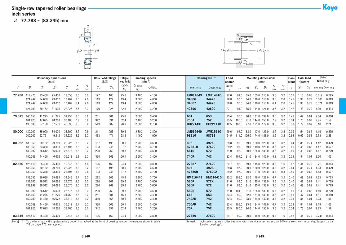
r
r1
u d
C
B
T
u D
a
u dau Dbu dbu Da
ra
rb
inch seriesSingle-row tapered roller bearings
77.788 117.475 25.400 25.400 19.050 3.6 3.2 127 166 25.1 3 100 4 100 LM814849 LM814810 27.6 91.0 85.0 105.0 113.0 3.6 3.2 0.51 1.18 0.65 0.619 0.29577.788 121.442 24.608 23.012 17.462 3.6 2.0 113 127 19.4 3 000 4 000 34306 34478 26.8 90.0 84.0 110.0 116.0 3.6 2.0 0.45 1.33 0.73 0.583 0.31377.788 121.442 24.608 23.012 17.462 6.4 2.0 113 127 19.4 3 000 4 000 34307 34478 26.8 96.0 84.0 110.0 116.0 6.4 2.0 0.45 1.33 0.73 0.571 0.313
77.788 127.000 30.162 31.000 22.225 3.6 3.2 179 225 32.3 2 400 3 200 42690 42620 27.1 91.0 85.0 114.0 121.0 3.6 3.2 0.42 1.43 0.79 1.00 0.434
79.375 146.050 41.275 41.275 31.750 3.6 3.2 261 301 45.3 2 600 3 400 661 653 33.4 96.0 90.0 131.0 139.0 3.6 3.2 0.41 1.47 0.81 2.04 0.88079.375 161.925 47.625 48.260 38.100 7.9 3.2 342 391 52.4 2 400 3 200 756A 752 35.5 106.0 91.0 144.0 150.0 7.9 3.2 0.34 1.76 0.97 2.95 1.5979.375 190.500 57.150 57.531 46.038 3.6 3.2 549 602 76.9 2 000 2 700 HH221431 HH221410 42.5 103.0 97.0 171.0 179.0 3.6 3.2 0.33 1.79 0.99 6.16 2.21
80.000 130.000 35.000 34.000 28.500 3.2 2.5 211 256 39.3 2 800 3 800 JM515649 JM515610 29.6 94.0 88.0 117.0 125.0 3.2 2.5 0.39 1.54 0.85 1.19 0.57580.000 200.000 52.761 49.212 34.925 3.6 3.2 433 471 58.8 1 400 1 900 98316 98788 54.5 111.0 105.0 174.0 188.0 3.6 3.2 0.63 0.95 0.52 5.73 2.28
80.962 133.350 30.162 29.769 22.225 3.6 3.2 167 198 30.0 2 700 3 600 496 492A 29.8 95.0 89.0 120.0 128.0 3.6 3.2 0.44 1.35 0.74 1.12 0.42980.962 133.350 33.338 33.338 26.195 3.6 3.2 193 245 37.2 2 700 3 700 47681R 47620 29.2 95.0 89.0 119.0 128.0 3.6 3.2 0.40 1.48 0.82 1.17 0.57780.962 139.992 36.512 36.098 28.575 3.6 3.2 220 262 39.8 2 700 3 600 581R 572 31.0 96.0 90.0 125.0 133.0 3.6 3.2 0.40 1.49 0.82 1.47 0.779
80.962 150.089 44.450 46.672 36.512 5.2 3.2 330 368 50.1 2 500 3 400 740R 742 32.4 101.0 91.0 134.0 142.0 5.2 3.2 0.33 1.84 1.01 2.30 1.06
82.550 125.412 25.400 25.400 19.845 3.6 1.6 126 162 24.4 2 900 3 800 27687 27620 24.7 96.0 89.0 115.0 120.0 3.6 1.6 0.42 1.44 0.79 0.710 0.34482.550 133.350 30.162 29.769 22.225 3.6 3.2 167 198 30.0 2 700 3 600 495 492A 29.8 97.0 90.0 120.0 128.0 3.6 3.2 0.44 1.35 0.74 1.08 0.42982.550 133.350 33.338 33.338 26.195 3.6 0.8 193 245 37.2 2 700 3 700 47686R 47620A 29.2 97.0 90.0 121.0 128.0 3.6 0.8 0.40 1.48 0.82 1.13 0.577
82.550 133.350 39.688 39.688 32.545 6.7 3.2 222 306 45.9 2 800 3 700 HM516448 HM516410 32.2 105.0 92.0 118.0 128.0 6.7 3.2 0.40 1.49 0.82 1.33 0.76382.550 139.700 36.512 36.098 28.575 3.6 3.2 220 262 39.8 2 700 3 600 580R 572X 31.0 98.0 91.0 125.0 133.0 3.6 3.2 0.40 1.49 0.82 1.41 0.76582.550 139.992 36.512 36.098 28.575 3.6 3.2 220 262 39.8 2 700 3 600 580R 572 31.0 98.0 91.0 125.0 133.0 3.6 3.2 0.40 1.49 0.82 1.41 0.779
82.550 139.992 36.512 36.098 28.575 6.7 3.2 220 262 39.8 2 700 3 600 582R 572 31.0 104.0 91.0 125.0 133.0 6.7 3.2 0.40 1.49 0.82 1.40 0.77982.550 146.050 41.275 41.275 31.750 3.6 3.2 261 301 45.3 2 600 3 400 663 653 33.4 99.0 92.0 131.0 139.0 3.6 3.2 0.41 1.47 0.81 1.91 0.88082.550 150.089 44.450 46.672 36.512 3.6 3.2 330 368 50.1 2 500 3 400 749AR 742 32.4 99.0 93.0 134.0 142.0 3.6 3.2 0.33 1.84 1.01 2.23 1.06
82.550 150.089 44.450 46.672 36.512 6.7 3.2 330 368 50.1 2 500 3 400 750AR 742 32.4 106.0 93.0 134.0 142.0 6.7 3.2 0.33 1.84 1.01 2.19 1.0682.550 161.925 47.625 48.260 38.100 3.6 3.2 342 391 52.4 2 400 3 200 757 752 35.5 100.0 94.0 144.0 150.0 3.6 3.2 0.34 1.76 0.97 2.83 1.59
83.345 125.412 25.400 25.400 19.845 0.8 1.6 126 162 24.4 2 900 3 800 27689 27620 24.7 90.0 90.0 115.0 120.0 0.8 1.6 0.42 1.44 0.79 0.746 0.344
Boundary dimensions Basic load ratings Fatigue Limiting speeds Bearing No. 1) Loadcenter(mm)
a
Mounting dimensions Con-stant
Axial load factors
(Refer.)
Mass (kg)(mm) (kN) load limit (min−1) (mm)
d D T B Cr r1 Cr C0r
(kN) Grease lub.
Oil lub. Inner ring Outer ring da db Da Dbra rb e Y1 Y0 Inner ring Outer ring
min. min. Cu max. max.
[Note] 1) To the bearings with supplementary code "J" attached at the front of bearing number, tolerances shown in table7-8 on page A72 are applied.
[Remark] Inch series tapered roller bearings with bore diameter larger than 100 mm are shown in catalog "large size ball& roller bearings".
B 248 B 249
d 77.788 ∼ (83.345) mm

r
r1
u d
C
B
T
u D
a
u dau Dbu dbu Da
ra
rb
inch seriesSingle-row tapered roller bearings
83.345 125.412 25.400 25.400 19.845 3.6 1.6 126 162 24.4 2 900 3 800 27690 27620 24.7 96.0 90.0 115.0 120.0 3.6 1.6 0.42 1.44 0.79 0.689 0.34483.345 125.412 25.400 25.400 19.845 6.4 1.6 126 162 24.4 2 900 3 800 27691 27620 24.7 102.0 90.0 115.0 120.0 6.4 1.6 0.42 1.44 0.79 0.646 0.344
84.138 133.350 30.162 29.769 22.225 3.6 3.2 167 198 30.0 2 700 3 600 498 492A 29.8 98.0 91.0 120.0 128.0 3.6 3.2 0.44 1.35 0.74 1.04 0.429
85.000 130.000 30.000 29.000 24.000 3.0 2.5 179 228 34.5 2 800 3 700 JM716649 JM716610 29.1 98.0 92.0 117.0 125.0 3.0 2.5 0.44 1.35 0.74 0.937 0.45685.000 140.000 39.000 38.000 31.500 3.0 2.5 254 308 46.4 2 700 3 500 JHM516849 JHM516810 32.8 100.0 93.9 125.0 134.0 3.0 2.5 0.41 1.47 0.81 1.54 0.75985.000 150.000 46.000 46.000 38.000 3.0 2.5 342 390 53.1 2 500 3 400 JH217249 JH217210 33.6 101.0 95.2 134.0 142.0 3.0 2.5 0.33 1.80 0.99 2.28 1.08
85.000 200.000 52.761 49.212 34.925 3.6 3.2 433 471 58.8 1 400 1 900 98335 98788 54.5 115.0 109.0 174.0 188.0 3.6 3.2 0.63 0.95 0.52 5.47 2.28
85.026 150.089 44.450 46.672 36.512 3.6 3.2 330 368 50.1 2 500 3 400 749R 742 32.4 101.0 95.0 134.0 142.0 3.6 3.2 0.33 1.84 1.01 2.12 1.0685.026 150.089 44.450 46.672 36.512 5.2 3.2 330 368 50.1 2 500 3 400 749SR 742 32.4 104.0 95.0 134.0 142.0 5.2 3.2 0.33 1.84 1.01 2.08 1.06
85.725 133.350 30.162 29.769 22.225 3.6 3.2 167 198 30.0 2 700 3 600 497 492A 29.8 99.0 93.0 120.0 128.0 3.6 3.2 0.44 1.35 0.74 0.978 0.42985.725 136.525 30.162 29.769 22.225 6.4 3.2 167 198 30.0 2 700 3 600 497A 493 29.8 105.0 93.0 122.0 130.0 6.4 3.2 0.44 1.35 0.74 0.965 0.54485.725 142.138 42.862 42.862 34.133 4.8 3.2 276 351 52.4 2 600 3 500 HM617049 HM617010 35.2 106.0 95.7 125.0 137.0 4.8 3.2 0.43 1.39 0.76 1.72 0.902
85.725 146.050 41.275 41.275 31.750 3.6 3.2 261 301 45.3 2 600 3 400 665 653 33.4 102.0 95.0 131.0 139.0 3.6 3.2 0.41 1.47 0.81 1.77 0.88085.725 146.050 41.275 41.275 31.750 6.4 3.2 261 301 45.3 2 600 3 400 665A 653 33.4 107.0 95.0 131.0 139.0 6.4 3.2 0.41 1.47 0.81 1.76 0.88085.725 152.400 39.688 36.322 30.162 3.6 3.2 230 287 42.5 2 400 3 300 596 592A 37.1 102.0 96.0 135.0 144.0 3.6 3.2 0.44 1.36 0.75 1.83 1.04
85.725 161.925 47.625 48.260 38.100 3.6 3.2 342 391 52.4 2 400 3 200 758 752 35.5 103.0 97.0 144.0 150.0 3.6 3.2 0.34 1.76 0.97 2.67 1.5985.725 168.275 41.275 41.275 30.162 3.6 3.2 282 349 50.4 2 200 3 000 677 672 38.6 105.0 99.0 149.0 160.0 3.6 3.2 0.47 1.28 0.70 2.89 1.2285.725 168.275 53.975 56.363 41.275 3.6 3.2 429 467 62.1 2 300 3 100 841R 832 35.0 104.0 97.0 149.0 155.0 3.6 3.2 0.30 2.00 1.10 3.47 1.72
88.900 123.825 20.638 20.638 16.670 1.6 1.6 102 145 21.5 2 800 3 700 L217849 L217810 20.7 97.0 94.0 116.0 119.0 1.6 1.6 0.33 1.82 1.00 0.507 0.23588.900 152.400 39.688 39.688 30.162 6.4 3.2 311 359 53.5 2 400 3 200 HM518445 HM518410 33.1 110.0 98.0 135.0 146.0 6.4 3.2 0.40 1.49 0.82 2.10 0.76888.900 161.925 47.625 48.260 38.100 3.6 3.2 342 391 52.4 2 400 3 200 759 752 35.5 106.0 99.0 144.0 150.0 3.6 3.2 0.34 1.76 0.97 2.50 1.59
88.900 161.925 47.625 48.260 38.100 7.1 3.2 342 391 52.4 2 400 3 200 766 752 35.5 113.0 99.0 144.0 150.0 7.1 3.2 0.34 1.76 0.97 2.48 1.5988.900 161.925 53.975 55.100 42.862 3.6 3.2 395 471 61.4 2 400 3 200 6580R 6535 49.8 109.0 98.0 141.0 154.0 3.6 3.2 0.40 1.50 0.82 3.09 1.6588.900 168.275 41.275 41.275 30.162 3.6 3.2 282 349 50.4 2 200 3 000 679 672 38.6 107.0 101.0 149.0 160.0 3.6 3.2 0.47 1.28 0.70 2.75 1.22
88.900 190.500 57.150 57.531 44.450 7.9 3.2 482 565 72.4 2 100 2 700 855R 854 40.0 118.0 103.0 170.0 174.0 7.9 3.2 0.33 1.79 0.99 5.05 2.66
Boundary dimensions Basic load ratings Fatigue Limiting speeds Bearing No. 1) Loadcenter(mm)
a
Mounting dimensions Con-stant
Axial load factors
(Refer.)
Mass (kg)(mm) (kN) load limit (min−1) (mm)
d D T B Cr r1 Cr C0r
(kN) Grease lub.
Oil lub. Inner ring Outer ring da db Da Dbra rb e Y1 Y0 Inner ring Outer ring
min. min. Cu max. max.
[Note] 1) To the bearings with supplementary code "J" attached at the front of bearing number, tolerances shown in table7-8 on page A72 are applied.
[Remark] Inch series tapered roller bearings with bore diameter larger than 100 mm are shown in catalog "large size ball& roller bearings".
B 250 B 251
d (83.345) ∼ (88.900) mm

r
r1
u d
C
B
T
u D
a
u dau Dbu dbu Da
ra
rb
inch seriesSingle-row tapered roller bearings
88.900 190.500 57.150 57.531 46.038 7.9 3.2 549 602 76.9 2 000 2 700 HH221434 HH221410 42.5 120.0 105.0 171.0 179.0 7.9 3.2 0.33 1.79 0.99 5.57 2.2188.900 200.000 52.761 49.212 34.925 3.6 3.2 433 471 58.8 1 400 1 900 98350 98788 54.5 118.0 112.0 174.0 188.0 3.6 3.2 0.63 0.95 0.52 5.27 2.28
89.974 146.975 40.000 40.000 32.500 7.1 3.6 259 310 46.6 2 500 3 300 HM218248 HM218210 30.8 112.0 99.0 133.0 141.0 7.1 3.6 0.33 1.80 0.99 1.66 0.784
90.000 145.000 35.000 34.000 27.000 3.0 2.5 244 291 43.5 2 500 3 400 JM718149 JM718110 32.7 105.0 99.0 131.0 139.0 3.0 2.5 0.44 1.35 0.74 1.47 0.65290.000 155.000 44.000 44.000 35.500 3.0 2.5 363 407 54.8 2 400 3 200 JHM318448 JHM318410 34.5 106.0 100.0 140.0 148.0 3.0 2.5 0.34 1.76 0.97 2.37 1.0090.000 161.925 53.975 55.100 42.862 3.0 3.2 395 471 61.4 2 400 3 200 6581XR 6535 41.0 102.0 98.0 141.0 154.0 3.0 3.2 0.40 1.50 0.82 3.02 1.65
90.488 161.925 47.625 48.260 38.100 3.6 3.2 342 391 52.4 2 400 3 200 760 752 35.5 107.0 101.0 144.0 150.0 3.6 3.2 0.34 1.76 0.97 2.42 1.59
92.075 146.050 33.338 34.925 26.195 3.6 3.2 223 293 43.2 2 500 3 300 47890R 47820 32.6 107.0 101.0 131.0 140.0 3.6 3.2 0.45 1.34 0.74 1.46 0.65792.075 168.275 41.275 41.275 30.162 3.6 3.2 282 349 50.4 2 200 3 000 681 672 38.6 110.0 104.0 149.0 160.0 3.6 3.2 0.47 1.28 0.70 2.61 1.2292.075 168.275 41.275 41.275 30.162 6.4 3.2 282 349 50.4 2 200 3 000 681A 672 38.6 116.0 104.0 149.0 160.0 6.4 3.2 0.47 1.28 0.70 2.60 1.22
92.075 180.975 47.625 48.006 38.100 3.6 3.2 362 438 56.6 2 100 2 800 778 772 39.5 111.0 105.0 161.0 168.0 3.6 3.2 0.39 1.56 0.86 3.65 1.9292.075 190.500 57.150 57.531 44.450 7.9 3.2 482 565 72.4 2 100 2 700 857R 854 39.9 121.0 106.0 170.0 174.0 7.9 3.2 0.33 1.79 0.99 4.86 2.66
95.000 150.000 35.000 34.000 27.000 3.0 2.5 235 294 43.4 2 400 3 300 JM719149 JM719113 33.5 109.0 104.0 135.0 143.0 3.0 2.5 0.44 1.36 0.75 1.43 0.766
95.250 128.588 15.875 15.083 11.908 1.6 1.6 72.6 93.0 13.1 2 600 3 500 LL319349 LL319310 20.3 103.0 100.0 122.0 125.0 1.6 1.6 0.35 1.71 0.94 0.393 0.14795.250 130.175 20.638 21.432 16.670 1.6 1.6 121 167 24.7 2 600 3 500 L319249 L319210 22.2 107.0 101.0 122.0 125.0 1.6 1.6 0.35 1.72 0.95 0.548 0.24695.250 146.050 33.338 34.925 26.195 3.6 3.2 223 293 43.2 2 500 3 300 47896R 47820 32.6 110.0 103.0 131.0 140.0 3.6 3.2 0.45 1.34 0.74 1.34 0.657
95.250 147.638 35.717 36.322 26.192 5.2 0.8 230 287 42.5 2 400 3 300 594A 592XE 33.4 113.0 104.0 135.0 142.0 5.2 0.8 0.44 1.36 0.75 1.45 0.62095.250 157.162 36.512 36.116 26.195 3.6 3.2 227 288 41.7 2 300 3 000 52375 52618 36.0 112.0 105.0 142.0 153.0 3.6 3.2 0.47 1.26 0.69 1.94 0.69495.250 168.275 41.275 41.275 30.162 3.6 3.2 282 349 50.4 2 200 3 000 683 672 38.6 113.0 106.0 149.0 160.0 3.6 3.2 0.47 1.28 0.70 2.46 1.22
95.250 190.500 57.150 57.531 44.450 7.9 3.2 482 565 72.4 2 100 2 700 864R 854 39.9 123.0 108.0 170.0 174.0 7.9 3.2 0.33 1.79 0.99 4.64 2.6695.250 190.500 57.150 57.531 46.038 7.9 3.2 549 602 76.9 2 000 2 700 HH221440 HH221410 42.5 125.0 110.0 171.0 179.0 7.9 3.2 0.33 1.79 0.99 5.16 2.21
98.425 168.275 41.275 41.275 30.162 3.6 3.2 282 349 50.4 2 200 3 000 685 672 38.6 116.0 109.0 149.0 160.0 3.6 3.2 0.47 1.28 0.70 2.29 1.2298.425 190.500 57.150 57.531 46.038 3.6 3.2 549 602 76.9 2 000 2 700 HH221442 HH221410 42.5 119.0 113.0 171.0 179.0 3.6 3.2 0.33 1.79 0.99 4.97 2.21
99.975 212.725 66.675 66.675 53.975 3.6 3.2 641 699 87.1 1 800 2 400 HH224334 HH224310 47.6 122.0 117.0 192.0 202.0 3.6 3.2 0.33 1.84 1.01 7.91 3.03
Boundary dimensions Basic load ratings Fatigue Limiting speeds Bearing No. 1) Loadcenter(mm)
a
Mounting dimensions Con-stant
Axial load factors
(Refer.)
Mass (kg)(mm) (kN) load limit (min−1) (mm)
d D T B Cr r1 Cr C0r
(kN) Grease lub.
Oil lub. Inner ring Outer ring da db Da Dbra rb e Y1 Y0 Inner ring Outer ring
min. min. Cu max. max.
[Note] 1) To the bearings with supplementary code "J" attached at the front of bearing number, tolerances shown in table7-8 on page A72 are applied.
[Remark] Inch series tapered roller bearings with bore diameter larger than 100 mm are shown in catalog "large size ball& roller bearings".
B 252 B 253
d (88.900) ∼ 99.975 mm

r
r1
u d
C
B
T
u D
a
u dau Dbu dbu Da
ra
rb
inch seriesSingle-row tapered roller bearings
99.982 190.500 57.150 57.531 46.038 6.4 3.2 549 602 76.9 2 000 2 700 HH221447 HH221410 42.5 126.0 114.0 171.0 179.0 6.4 3.2 0.33 1.79 0.99 4.84 2.21
100.000 155.000 36.000 35.000 28.000 3.0 2.5 256 328 47.7 2 300 3 100 JM720249 JM720210 35.6 110.0 110.0 139.0 148.0 3.0 2.5 0.47 1.27 0.70 1.64 0.763100.000 160.000 41.000 40.000 32.000 3.0 2.5 298 378 54.6 2 300 3 000 JHM720249 JHM720210 38.3 110.0 111.0 143.0 153.0 3.0 2.5 0.47 1.28 0.70 2.11 0.964
100.012 157.162 36.512 36.116 26.195 3.6 3.2 227 288 41.7 2 300 3 000 52393 52618 36.0 113.0 115.0 142.0 153.0 3.6 3.2 0.47 1.26 0.69 1.74 0.694
101.600 157.162 36.512 36.116 26.195 3.6 3.2 227 288 41.7 2 300 3 000 52400 52618 36.0 114.0 115.0 142.0 153.0 3.6 3.2 0.47 1.26 0.69 1.67 0.694101.600 157.162 36.512 36.116 26.195 7.9 3.2 227 288 41.7 2 300 3 000 52401 52618 36.0 126.0 111.0 142.0 153.0 7.9 3.2 0.47 1.26 0.69 1.64 0.694101.600 168.275 41.275 41.275 30.162 3.6 3.2 282 349 50.4 2 200 3 000 687 672 38.6 114.0 115.0 146.0 157.0 3.6 3.2 0.47 1.28 0.70 2.15 1.22
101.600 180.975 47.625 48.006 38.100 3.6 3.2 362 438 56.6 2 100 2 800 780 772 39.5 114.0 120.0 156.0 165.0 3.6 3.2 0.39 1.56 0.86 3.09 1.92101.600 190.500 57.150 57.531 44.450 7.9 3.2 482 565 72.4 2 100 2 700 861R 854 39.9 129.0 114.0 170.0 174.0 7.9 3.2 0.33 1.79 0.99 4.20 2.66101.600 190.500 57.150 57.531 46.038 7.9 3.2 549 602 76.9 2 000 2 700 HH221449 HH221410 42.5 123.0 119.0 168.0 178.0 7.9 3.2 0.33 1.79 0.99 4.72 2.21
101.600 200.000 52.761 49.212 34.925 3.6 3.2 433 471 58.8 1 400 1 900 98400 98788 54.5 114.0 123.0 170.0 185.0 3.6 3.2 0.63 0.95 0.52 4.55 2.28101.600 212.725 66.675 66.675 53.975 7.1 3.2 563 674 84.1 1 800 2 400 941 932 47.6 121.0 135.0 181.0 192.0 7.1 3.2 0.33 1.84 1.01 7.07 4.07101.600 212.725 66.675 66.675 53.975 7.1 3.2 641 699 87.1 1 800 2 400 HH224335 HH224310 47.6 121.0 134.0 189.0 201.0 7.1 3.2 0.33 1.84 1.01 7.76 3.03
104.775 180.975 47.625 48.006 38.100 3.6 3.2 362 438 56.6 2 100 2 800 782 772 39.5 117.0 120.0 156.0 165.0 3.6 3.2 0.39 1.56 0.86 2.90 1.92104.775 180.975 47.625 48.006 38.100 6.4 3.2 362 438 56.6 2 100 2 800 786 772 39.5 123.0 120.0 156.0 165.0 6.4 3.2 0.39 1.56 0.86 2.88 1.92104.775 180.975 47.625 48.006 38.100 7.1 3.2 362 438 56.6 2 100 2 800 787 772 39.5 129.0 116.0 161.0 168.0 7.1 3.2 0.39 1.56 0.86 2.87 1.92
104.775 190.500 47.625 49.212 34.925 3.6 3.2 381 483 60.9 1 900 2 600 71412 71750 40.9 117.0 131.0 167.0 177.0 3.6 3.2 0.42 1.44 0.79 3.96 1.72
106.362 165.100 36.512 36.512 26.988 3.6 3.2 245 325 46.3 2 200 2 900 56418R 56650 38.6 122.0 116.0 149.0 159.0 3.6 3.2 0.50 1.21 0.66 1.84 0.852
107.950 146.050 21.432 21.432 16.670 1.6 1.6 108 167 23.5 2 300 3 100 L521949R L521910 26.2 116.0 114.0 136.0 141.0 1.6 1.6 0.39 1.53 0.84 0.665 0.325107.950 158.750 23.020 21.438 15.875 3.6 3.2 130 169 23.9 2 200 3 000 37425 37625 36.5 121.0 121.0 141.0 148.0 3.6 3.2 0.61 0.99 0.54 0.893 0.484107.950 159.987 34.925 34.925 26.988 3.6 3.2 231 319 45.8 2 200 2 900 LM522546 LM522510 32.9 122.0 116.0 146.0 154.0 3.6 3.2 0.40 1.50 0.82 1.64 0.784
107.950 161.925 34.925 34.925 26.988 3.6 3.2 216 293 41.8 2 200 2 900 48190 48120 39.1 121.0 120.0 145.0 154.0 3.6 3.2 0.51 1.19 0.65 1.57 0.820107.950 165.100 36.512 36.512 26.988 3.6 3.2 245 325 46.3 2 200 2 900 56425R 56650 38.6 123.0 117.0 149.0 159.0 3.6 3.2 0.50 1.21 0.66 1.76 0.852107.950 168.275 36.512 36.512 26.988 3.6 3.2 245 325 46.3 2 200 2 900 56425R 56662 38.6 123.0 117.0 150.0 160.0 3.6 3.2 0.50 1.21 0.66 1.76 1.03
107.950 190.500 47.625 49.212 34.925 3.6 3.2 381 483 60.9 1 900 2 600 71425 71750 40.9 121.0 131.0 167.0 177.0 3.6 3.2 0.42 1.44 0.79 3.76 1.72
Boundary dimensions Basic load ratings Fatigue Limiting speeds Bearing No. 1) Loadcenter(mm)
a
Mounting dimensions Con-stant
Axial load factors
(Refer.)
Mass (kg)(mm) (kN) load limit (min−1) (mm)
d D T B Cr r1 Cr C0r
(kN) Grease lub.
Oil lub. Inner ring Outer ring da db Da Dbra rb e Y1 Y0 Inner ring Outer ring
min. min. Cu max. max.
[Note] 1) To the bearings with supplementary code "J" attached at the front of bearing number, tolerances shown in table7-8 on page A72 are applied.
[Remark] Inch series tapered roller bearings with bore diameter larger than 100 mm are shown in catalog "large size ball& roller bearings".
B 254 B 255
d 99.982 ∼ (107.950) mm

r
r1
u d
C
B
T
u D
a
u dau Dbu dbu Da
ra
rb
inch seriesSingle-row tapered roller bearings
107.950 212.725 66.675 66.675 53.975 7.9 3.2 563 674 84.1 1 800 2 400 936 932 47.6 137.0 122.0 187.0 193.0 7.9 3.2 0.33 1.84 1.01 6.52 4.07107.950 212.725 66.675 66.675 53.975 7.9 3.2 641 699 87.1 1 800 2 400 HH224340 HH224310 47.6 129.0 134.0 189.0 201.0 7.9 3.2 0.33 1.84 1.01 7.21 3.03
109.538 158.750 23.020 21.438 15.875 3.6 3.2 130 169 23.9 2 200 3 000 37431 37625 36.5 123.0 116.0 143.0 152.0 6.4 6.4 0.61 0.99 0.54 0.848 0.484
109.987 159.987 34.925 34.925 26.988 7.9 3.2 231 319 45.8 2 200 2 900 LM522548 LM522510 32.9 131.0 121.0 146.0 154.0 7.9 3.2 0.40 1.50 0.82 1.52 0.784109.987 159.987 34.925 34.925 26.988 3.6 3.2 231 319 45.8 2 200 2 900 LM522549 LM522510 32.9 123.0 121.0 146.0 154.0 3.6 3.2 0.40 1.50 0.82 1.55 0.784
109.992 177.800 41.275 41.275 30.162 3.6 3.2 294 380 53.4 2 000 2 700 64433R 64700 42.8 128.0 121.0 160.0 172.6 3.6 3.2 0.52 1.16 0.64 2.69 1.10
110.000 165.000 35.000 35.000 26.500 3.0 2.5 245 325 46.3 2 200 2 900 JM822049 JM822010 38.1 121.0 121.0 148.0 157.0 3.0 2.5 0.50 1.21 0.66 1.64 0.826110.000 180.000 47.000 46.000 38.000 3.0 2.5 385 487 62.3 2 000 2 700 JHM522649 JHM522610 40.6 121.0 125.0 160.0 171.0 3.0 2.5 0.41 1.48 0.81 3.08 1.49
114.300 177.800 41.275 41.275 30.162 3.6 3.2 294 380 53.4 2 000 2 700 64450R 64700 42.8 131.0 125.0 160.0 172.0 3.6 3.2 0.52 1.16 0.64 2.45 1.10114.300 180.975 34.925 31.750 25.400 3.6 3.2 216 247 35.1 2 000 2 700 68450 68712 40.6 127.0 131.0 161.0 170.0 3.6 3.2 0.50 1.21 0.66 1.89 1.04114.300 190.500 47.625 49.212 34.925 3.6 3.2 381 483 60.9 1 900 2 600 71450 71750 40.9 127.0 131.0 167.0 177.0 3.6 3.2 0.42 1.44 0.79 3.33 1.72
114.300 212.725 66.675 66.675 53.975 7.1 3.2 563 674 84.1 1 800 2 400 938 932 47.6 141.0 128.0 187.0 193.0 7.1 3.2 0.33 1.84 1.01 5.96 4.07114.300 212.725 66.675 66.675 53.975 7.1 3.2 641 699 87.1 1 800 2 400 HH224346 HH224310 47.6 134.0 134.0 189.0 201.0 7.1 3.2 0.33 1.84 1.01 6.64 3.03114.300 273.050 82.550 82.550 53.975 6.4 6.4 885 898 104 1 500 1 900 HH926744 HH926710 76.1 133.0 151.0 230.0 252.0 6.4 6.4 0.63 0.95 0.52 15.0 6.97
114.976 212.725 66.675 66.675 53.975 7.1 3.2 641 699 87.1 1 800 2 400 HH224349 HH224310 47.6 135.0 134.0 189.0 201.0 7.1 3.2 0.33 1.84 1.01 6.58 3.03
115.087 190.500 47.625 49.212 34.925 3.6 3.2 381 483 60.9 1 900 2 600 71453 71750 40.9 133.0 126.0 171.0 181.0 3.6 3.2 0.42 1.44 0.79 3.28 1.72115.087 190.500 47.625 49.212 34.925 7.9 3.2 381 483 60.9 1 900 2 600 71455 71750 40.9 136.0 131.0 167.0 177.0 7.9 3.2 0.42 1.44 0.79 3.25 1.72
117.475 180.975 34.925 31.750 25.400 3.6 3.2 216 247 35.1 2 000 2 700 68462 68712 40.6 130.0 131.0 161.0 170.0 3.6 3.2 0.50 1.21 0.66 1.75 1.04117.475 180.975 34.925 31.750 25.400 7.9 3.2 216 247 35.1 2 000 2 700 68463 68712 40.6 141.0 125.0 163.0 172.0 7.9 3.2 0.50 1.21 0.66 1.61 1.05
120.650 190.500 46.038 46.038 34.925 3.6 1.6 393 512 63.9 1 900 2 500 HM624749 HM624710 41.6 146.0 132.0 174.0 184.0 3.6 1.6 0.43 1.41 0.77 3.20 1.44120.650 254.000 77.788 82.550 61.912 9.5 6.4 895 1 050 125 1 500 2 000 HH228340 HH228310 54.3 158.0 142.0 223.0 234.0 9.5 6.4 0.32 1.87 1.03 12.6 6.00
127.000 254.000 77.788 82.550 61.912 9.5 6.4 895 1 050 125 1 500 2 000 HH228349 HH228310 54.3 164.0 148.0 223.0 234.0 9.5 6.4 0.32 1.87 1.03 11.8 6.00
Boundary dimensions Basic load ratings Fatigue Limiting speeds Bearing No. 1) Loadcenter(mm)
a
Mounting dimensions Con-stant
Axial load factors
(Refer.)
Mass (kg)(mm) (kN) load limit (min−1) (mm)
d D T B Cr r1 Cr C0r
(kN) Grease lub.
Oil lub. Inner ring Outer ring da db Da Dbra rb e Y1 Y0 Inner ring Outer ring
min. min. Cu max. max.
[Note] 1) To the bearings with supplementary code "J" attached at the front of bearing number, tolerances shown in table7-8 on page A72 are applied.
[Remark] Inch series tapered roller bearings with bore diameter larger than 100 mm are shown in catalog "large size ball& roller bearings".
B 256 B 257
d (107.950) ∼ 127.000 mm

r
r1
u d
C
B
T
u D
a
u dau Dbu dbu Da
ra
rb
inch seriesSingle-row tapered roller bearings
133.350 177.008 25.400 26.195 20.638 1.6 1.6 176 278 38.2 1 900 2 500 L327249 L327210 29.1 142.0 145.0 164.0 171.0 1.6 1.6 0.35 1.72 0.95 1.14 0.543
142.875 200.025 41.275 39.688 34.130 7.9 3.3 307 491 66.5 1 700 2 200 48684 48620 38.4 166.0 151.0 185.0 193.0 7.9 3.3 0.34 1.78 0.98 2.43 1.38142.875 200.025 41.275 39.688 34.130 3.6 3.3 307 491 66.5 1 700 2 200 48685 48620 38.4 156.0 157.0 182.0 192.0 3.6 3.3 0.34 1.78 0.98 2.46 1.38
170.000 230.000 39.000 38.000 31.000 3.0 2.5 363 558 72.8 1 400 1 900 JHM534149 JHM534110 43.6 181.0 184.0 214.0 222.0 3.0 2.5 0.38 1.57 0.86 3.17 1.29170.000 240.000 46.000 44.500 37.000 3.0 2.5 443 666 77.1 1 400 1 800 JM734449 JM734410 50.6 181.0 184.0 220.0 231.0 3.0 2.5 0.44 1.37 0.75 4.31 2.00
171.450 222.250 25.400 24.608 19.050 1.6 1.6 197 299 38.7 1 400 1 900 L435049 L435010 36.0 181.0 179.0 211.0 215.0 1.6 1.6 0.38 1.60 0.88 1.63 0.697
180.000 250.000 47.000 45.000 37.000 3.0 2.5 456 705 81.7 1 300 1 700 JM736149 JM736110 55.2 191.0 193.0 230.0 242.0 3.0 2.5 0.48 1.25 0.69 4.47 2.10
190.000 260.000 46.000 44.000 36.500 3.0 2.5 461 723 81.4 1 200 1 700 JM738249 JM738210 56.0 201.0 203.0 240.0 251.0 3.0 2.5 0.48 1.26 0.69 4.71 2.18
196.850 254.000 28.575 27.783 21.433 1.6 1.6 236 387 48.2 1 200 1 600 L540049 L540010 43.1 206.0 214.0 238.0 245.0 1.6 1.6 0.40 1.51 0.83 2.34 1.02
200.000 300.000 65.000 62.000 51.000 3.6 2.5 773 1 140 124 1 100 1 500 JHM840449 JHM840410 72.1 213.0 218.0 270.0 288.0 3.6 2.5 0.52 1.15 0.63 9.97 5.13
220.878 317.500 47.625 52.388 36.513 3.2 3.2 611 928 103 970 1 300 LM245833 LM245810 50.5 234.0 253.0 296.0 304.0 3.2 3.2 0.33 1.80 0.99 9.56 2.78
228.600 358.775 71.438 71.438 53.975 3.6 3.2 968 1 590 166 840 1 100 M249732 M249710 64.4 242.0 279.0 330.0 343.0 3.6 3.2 0.33 1.80 0.99 20.1 6.44
230.188 317.500 47.625 52.388 36.513 3.2 3.2 611 928 103 970 1 300 LM245846 LM245810 50.5 242.0 238.0 309.0 312.0 3.2 3.2 0.33 1.80 0.99 8.25 2.78
231.775 317.500 47.625 52.388 36.513 3.2 3.2 611 928 103 970 1 300 LM245848 LM245810 50.5 244.0 240.0 309.0 312.0 3.2 3.2 0.33 1.80 0.99 8.02 2.78231.775 336.550 65.088 65.088 50.800 6.4 3.2 887 1 380 150 920 1 200 M246942 M246910 59.9 258.0 249.0 313.0 322.0 6.4 3.2 0.33 1.80 0.99 13.1 5.44231.775 358.775 71.438 71.438 53.975 6.4 3.2 968 1 590 166 920 1 200 M249734 M249710 64.4 258.0 253.0 335.0 343.0 6.4 3.2 0.33 1.80 0.99 19.9 6.44
254.000 358.775 71.438 71.438 53.975 3.6 3.2 968 1 590 166 840 1 100 M249749 M249710 64.4 268.0 279.0 330.0 343.0 3.6 3.2 0.33 1.80 0.99 14.8 6.44
257.175 342.900 57.150 57.150 44.450 6.4 3.2 764 1 280 135 870 1 200 M349549 M349510 60.1 276.0 276.0 320.0 330.0 6.4 3.2 0.35 1.73 0.95 9.27 3.99
292.100 374.650 47.625 47.625 34.925 3.6 3.2 587 971 111 760 1 000 L555249 L555210 64.7 306.0 309.0 351.0 360.0 3.6 3.2 0.40 1.49 0.82 7.97 3.53
Boundary dimensions Basic load ratings Fatigue Limiting speeds Bearing No. 1) Loadcenter(mm)
a
Mounting dimensions Con-stant
Axial load factors
(Refer.)
Mass (kg)(mm) (kN) load limit (min−1) (mm)
d D T B Cr r1 Cr C0r
(kN) Grease lub.
Oil lub. Inner ring Outer ring da db Da Dbra rb e Y1 Y0 Inner ring Outer ring
min. min. Cu max. max.
[Note] 1) To the bearings with supplementary code "J" attached at the front of bearing number, tolerances shown in table7-8 on page A72 are applied.
[Remark] Inch series tapered roller bearings with bore diameter larger than 100 mm are shown in catalog "large size ball& roller bearings".
B 258 B 259
d 133.350 ∼ 292.100 mm

r
u d
C
u D
T
r1
u dau Da
ra
Sa
rb
TDO typeDouble-row tapered roller bearings
Boundary dimensions
Basic load ratings
Fatigue Limiting speeds
Bearing No.
Mounting dimensions Con-stant
Axial load factors
(Refer.)
Mass
(kg)
(mm) (kN)
load limit
(min
−
1
) (mm)
d D T Cr r
1
C
r
C
0r
(kN)
Grease lub. Oil lub.
d
a
D
a
S
a
r
a
r
b
e Y
2
Y
3
Y
0
min. min.
C
u
min. min. min. max. max.
25
62 40 29.5 1.5 0.6 85.2 84.9 5.80 4 500 6 400
46T30305DJR/29.5
33.5 58.5 5 1.5 0.6 0.83 0.82 1.22 0.8 0.592
30
72 45 31.5 1.5 0.6 109 110 7.70 3 900 5 400
46T30306DJR/31.5
38.5 68 6.5 1.5 0.6 0.83 0.82 1.22 0.8 0.872
35
80 51 35.5 2 0.6 135 138 9.85 3 400 4 800
46T30307DJR/35.5
45 76.5 7.5 2 0.6 0.83 0.82 1.22 0.8 1.2
40
80 45 37.5 1.5 0.6 134 138 10.3 4 000 5 300
46T30208JR/37.5
48.5 75 3.5 1.5 0.6 0.37 1.8 2.68 1.76 0.954
40
80 55 43.5 1.5 0.6 166 182 13.6 4 000 5 300
46T32208JR/43.5
48.5 75 5.5 1.5 0.6 0.37 1.8 2.68 1.76 1.19
40
90 56 39.5 2 0.6 172 180 13.1 3 000 4 200
46T30308DJR/39.5
50 86.5 8 2 0.6 0.83 0.82 1.22 0.8 1.67
40
90 56 45.5 2 0.6 194 202 15.5 3 600 4 900
46T30308JR/45.5
50 82 5 2 0.6 0.35 1.96 2.91 1.91 1.67
45
85 47 37.5 1.5 0.6 144 155 11.6 3 700 4 900
46T30209JR/37.5
53.5 80 4.5 1.5 0.6 0.4 1.67 2.48 1.63 1.1
45
85 55 43.5 1.5 0.6 180 207 15.6 3 700 4 900
46T32209JR-1/43.5
53.5 81 5.5 1.5 0.6 0.4 1.67 2.48 1.63 1.31
45
100 60 41.5 2 0.6 204 214 15.8 2 700 3 800
46T30309DJR/41.5
55 96 9 2 0.6 0.83 0.82 1.22 0.8 2.15
45
100 60 49.5 2 0.6 242 256 19.9 3 300 4 300
46T30309JR/49.5
55 93 5 2 0.6 0.35 1.96 2.91 1.91 2.2
50
90 49 39.5 1.5 0.6 164 183 13.8 3 400 4 600
46T30210JR/39.5
58.5 85 4.5 1.5 0.6 0.42 1.61 2.39 1.57 1.22
50
90 55 43.5 1.5 0.6 182 211 15.9 3 500 4 600
46T32210JR/43.5
58.5 85 5.5 1.5 0.6 0.42 1.61 2.39 1.57 1.39
50
110 64 51.5 2 0.6 295 305 24.0 3 000 4 000
46T30310JR/51.5
62 102 6 2 0.6 0.35 1.96 2.91 1.91 2.68
50
110 73 52.5 2 0.6 247 266 19.8 2 500 3 500
46T30310DJR/52.5
62 105 10 2 0.6 0.83 0.82 1.22 0.8 3.11
50
110 90 71.5 2 0.6 378 440 34.2 3 000 4 000
46T32310JR/71.5
62 102 9 2 0.6 0.35 1.96 2.91 1.91 3.95
55
100 51 41.5 2 0.6 203 226 17.3 3 100 4 100
46T30211JR/41.5
65 94 4.5 2 0.6 0.4 1.67 2.48 1.63 1.6
55
100 60 48.5 2 0.6 230 266 20.5 3 100 4 100
46T32211JR-1/48.5
65 95 5.5 2 0.6 0.4 1.67 2.48 1.63 1.87
55
120 70 49 2 0.6 276 297 22.3 2 300 3 200
46T30311DJR/49
67 113 10.5 2 0.6 0.83 0.82 1.22 0.8 3.54
55
120 70 57 2 0.6 320 341 27.0 2 700 3 600
46T30311JR/57
67 111 6.5 2 0.6 0.35 1.96 2.91 1.91 3.57
55
120 97 76 2 0.6 429 500 39.1 2 700 3 600
46T32311JR/76
67 111 10.5 2 0.6 0.35 1.96 2.91 1.91 4.98
60
110 53 43.5 2 0.6 228 254 19.7 2 800 3 800
46T30212JR/43.5
70 103 4.5 2 0.6 0.4 1.67 2.48 1.63 2.04
60
110 66 54.5 2 0.6 282 334 25.9 2 800 3 800
46T32212JR/54.5
70 104 5.5 2 0.6 0.4 1.67 2.48 1.63
⎯
60
130 74 51 2.5 1 327 359 27.1 2 100 2 900
46T30312DJR/51
74 124 11.5 2.5 1 0.83 0.82 1.22 0.8 4.45
60
130 74 59 2.5 1 372 401 31.9 2 500 3 300
46T30312JR/59
74 120 7.5 2.5 1 0.35 1.96 2.91 1.91 4.46
[Remark] Bearings not shown above (e.g. inch series) are shown in catalog "large size ball & roller bearings".
B 260 B 261
d
25
∼
(
60
)
mm
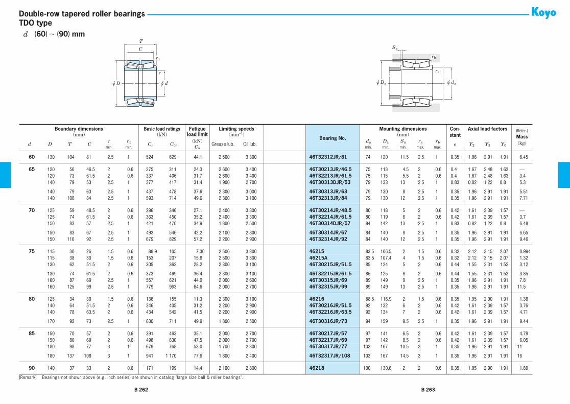
r
u d
C
u D
T
r1
u dau Da
ra
Sa
rb
TDO typeDouble-row tapered roller bearings
60
130 104 81 2.5 1 524 629 44.1 2 500 3 300
46T32312JR/81
74 120 11.5 2.5 1 0.35 1.96 2.91 1.91 6.45
65
120 56 46.5 2 0.6 275 311 24.3 2 600 3 400
46T30213JR/46.5
75 113 4.5 2 0.6 0.4 1.67 2.48 1.63
⎯
65
120 73 61.5 2 0.6 337 406 31.7 2 600 3 400
46T32213JR/61.5
75 115 5.5 2 0.6 0.4 1.67 2.48 1.63 3.4
65
140 79 53 2.5 1 377 417 31.4 1 900 2 700
46T30313DJR/53
79 133 13 2.5 1 0.83 0.82 1.22 0.8 5.3
65
140 79 63 2.5 1 437 478 37.6 2 300 3 000
46T30313JR/63
79 130 8 2.5 1 0.35 1.96 2.91 1.91 5.51
65
140 108 84 2.5 1 593 714 49.6 2 300 3 100
46T32313JR/84
79 130 12 2.5 1 0.35 1.96 2.91 1.91 7.71
70
125 59 48.5 2 0.6 296 346 27.1 2 400 3 300
46T30214JR/48.5
80 118 5 2 0.6 0.42 1.61 2.39 1.57
⎯
70
125 74 61.5 2 0.6 363 450 35.2 2 400 3 300
46T32214JR/61.5
80 119 6 2 0.6 0.42 1.61 2.39 1.57 3.7
70
150 83 57 2.5 1 421 470 34.9 1 800 2 500
46T30314DJR/57
84 142 13 2.5 1 0.83 0.82 1.22 0.8 6.48
70
150 83 67 2.5 1 493 546 42.2 2 100 2 800
46T30314JR/67
84 140 8 2.5 1 0.35 1.96 2.91 1.91 6.65
70
150 116 92 2.5 1 679 829 57.2 2 200 2 900
46T32314JR/92
84 140 12 2.5 1 0.35 1.96 2.91 1.91 9.46
75
115 30 26 1.5 0.6 89.9 105 7.30 2 500 3 300
46215
83.5 106.5 2 1.5 0.6 0.32 2.12 3.15 2.07 0.994
75
115 38 30 1.5 0.6 153 207 15.6 2 500 3 300
46215A
83.5 107.4 4 1.5 0.6 0.32 2.12 3.15 2.07 1.32
75
130 62 51.5 2 0.6 305 362 28.2 2 300 3 100
46T30215JR/51.5
85 124 5 2 0.6 0.44 1.55 2.31 1.52 3.12
75
130 74 61.5 2 0.6 373 469 36.4 2 300 3 100
46T32215JR/61.5
85 125 6 2 0.6 0.44 1.55 2.31 1.52 3.85
75
160 87 69 2.5 1 557 621 44.9 2 000 2 600
46T30315JR/69
89 149 9 2.5 1 0.35 1.96 2.91 1.91 7.8
75
160 125 99 2.5 1 779 963 64.6 2 000 2 700
46T32315JR/99
89 149 13 2.5 1 0.35 1.96 2.91 1.91 11.5
80
125 34 30 1.5 0.6 136 155 11.3 2 300 3 100
46216
88.5 116.9 2 1.5 0.6 0.35 1.95 2.90 1.91 1.38
80
140 64 51.5 2 0.6 346 405 31.2 2 200 2 900
46T30216JR/51.5
92 132 6 2 0.6 0.42 1.61 2.39 1.57 3.76
80
140 78 63.5 2 0.6 434 542 41.5 2 200 2 900
46T32216JR/63.5
92 134 7 2 0.6 0.42 1.61 2.39 1.57 4.71
80
170 92 73 2.5 1 630 711 49.9 1 800 2 500
46T30316JR/73
94 159 9.5 2.5 1 0.35 1.96 2.91 1.91 9.44
85
150 70 57 2 0.6 391 463 35.1 2 000 2 700
46T30217JR/57
97 141 6.5 2 0.6 0.42 1.61 2.39 1.57 4.79
85
150 86 69 2 0.6 498 630 47.5 2 000 2 700
46T32217JR/69
97 142 8.5 2 0.6 0.42 1.61 2.39 1.57 6.05
85
180 98 77 3 1 679 768 53.0 1 700 2 300
46T30317JR/77
103 167 10.5 3 1 0.35 1.96 2.91 1.91 11
85
180 137 108 3 1 941 1 170 77.6 1 800 2 400
46T32317JR/108
103 167 14.5 3 1 0.35 1.96 2.91 1.91 16
90
140 37 33 2 0.6 171 199 14.4 2 100 2 800
46218
100 130.6 2 2 0.6 0.35 1.95 2.90 1.91 1.89
Boundary dimensions
Basic load ratings
Fatigue Limiting speeds
Bearing No.
Mounting dimensions Con-stant
Axial load factors
(Refer.)
Mass
(kg)
(mm) (kN)
load limit
(min
−
1
) (mm)
d D T Cr r
1
C
r
C
0r
(kN)
Grease lub. Oil lub.
d
a
D
a
S
a
r
a
r
b
e Y
2
Y
3
Y
0
min. min.
C
u
min. min. min. max. max.
[Remark] Bearings not shown above (e.g. inch series) are shown in catalog "large size ball & roller bearings".
B 262 B 263
d
(
60
)
∼
(
90
)
mm

r
u d
C
u D
T
r1
u dau Da
ra
Sa
rb
TDO typeDouble-row tapered roller bearings
90
140 46 37 2 0.6 196 266 19.6 2 000 2 700
46218A
100 129.9 4.5 2 0.6 0.32 2.12 3.15 2.07 2.37
90
160 74 61 2 0.6 438 522 39.0 1 900 2 500
46T30218JR/61
102 150 6.5 2 0.6 0.42 1.61 2.39 1.57 5.85
90
160 94 77 2 0.6 565 724 53.7 1 900 2 500
46T32218JR/77
102 152 8.5 2 0.6 0.42 1.61 2.39 1.57 7.53
90
190 102 81 3 1 741 841 57.1 1 600 2 200
46T30318JR/81
108 177 10.5 3 1 0.35 1.96 2.91 1.91 13
90
190 144 115 3 1 989 1 230 78.7 1 700 2 200
46T32318JR/115
108 177 14.5 3 1 0.35 1.96 2.91 1.91 18.6
95
170 78 63 2.5 1 496 598 44.0 1 800 2 400
46T30219JR/63
109 159 7.5 2.5 1 0.42 1.61 2.39 1.57 7.01
95
170 100 83 2.5 1 667 877 64.1 1 800 2 400
46T32219JR/83
109 161 8.5 2.5 1 0.42 1.61 2.39 1.57 9.25
95
200 108 85 3 1 798 909 60.9 1 600 2 100
46T30319JR/85
113 186 11.5 3 1 0.35 1.96 2.91 1.91 14.8
95
200 151 118 3 1 1 110 1 390 89.2 1 600 2 100
46T32319JR/118
113 186 16.5 3 1 0.35 1.96 2.91 1.91 21.4
100
150 46 37 2 0.6 226 293 21.3 1 900 2 500
46220A
110 142 4.5 2 0.6 0.35 1.95 2.90 1.91 2.53
100
165 52 46 2.5 0.6 249 305 22.0 1 700 2 300
46320
112 154 3 2 0.6 0.35 1.95 2.90 1.91 4.03
100
165 65 52 2.5 0.6 333 443 32.4 1 800 2 300
46320A
112 153 6.5 2 0.6 0.35 1.95 2.90 1.91 4.97
100
180 83 67 2.5 1 554 676 49.1 1 700 2 200
46T30220JR/67
114 168 8 2.5 1 0.42 1.61 2.39 1.57 8.33
100
180 107 87 2.5 1 745 990 63.9 1 700 2 200
46T32220JR/87
114 171 10 2.5 1 0.42 1.61 2.39 1.57 11.1
100
215 112 87 3 1 906 1 040 68.0 1 500 1 900
46T30320JR/87
118 200 12.5 3 1 0.35 1.96 2.91 1.91 18.1
100
215 162 127 3 1 1 240 1 570 96.9 1 500 2 000
46T32320JR/127
118 200 17.5 3 1 0.35 1.96 2.91 1.91 27.2
105
190 88 70 2.5 1 618 761 52.3 1 600 2 100
46T30221JR/70
119 178 9 2.5 1 0.42 1.61 2.39 1.57 9.87
105
190 115 95 2.5 1 840 1 130 73.0 1 600 2 100
46T32221JR/95
119 180 10 2.5 1 0.42 1.61 2.39 1.57 13.5
105
225 116 91 3 1 995 1 160 73.6 1 400 1 800
46T30321JR/91 123 209 12.5 3 1 0.35 1.96 2.91 1.91 20.7
105 225 170 133 3 1 1 360 1 730 107 1 400 1 900 46T32321JR/133 123 209 18.5 3 1 0.35 1.96 2.91 1.91 30.9
110 170 45 40 2.5 0.6 219 304 21.2 1 700 2 200 46222 122 158 2.5 2 0.6 0.35 1.95 2.90 1.91 3.58110 180 56 50 2.5 0.6 308 388 27.7 1 600 2 100 46322 122 168 3 2 0.6 0.35 1.95 2.90 1.91 5.13110 180 70 56 2.5 0.6 391 533 38.1 1 600 2 100 46322A 122 168 7 2 0.6 0.35 1.92 2.86 1.88 6.43
110 200 92 74 2.5 1 695 868 58.1 1 500 2 000 46T30222JR/74 124 188 9 2.5 1 0.42 1.61 2.39 1.57 11.6110 200 121 101 2.5 1 938 1 280 80.4 1 500 2 000 46T32222JR/101 124 190 10 2.5 1 0.42 1.61 2.39 1.57 15.9110 240 118 93 3 1 1 030 1 180 75.2 1 300 1 700 46T30322JR/93 128 222 12.5 3 1 0.35 1.96 2.91 1.91 23.8
110 240 181 142 3 1 1 480 1 890 115 1 300 1 700 46T32322JR/142 128 222 19.5 3 1 0.35 1.96 2.91 1.91 37.3
Boundary dimensions Basic load ratings Fatigue Limiting speeds
Bearing No.
Mounting dimensions Con-stant
Axial load factors (Refer.)
Mass(kg)
(mm) (kN) load limit (min−1) (mm)
d D T Cr r1 Cr C0r
(kN)Grease lub. Oil lub.
da Da Sa ra rb e Y2 Y3 Y0min. min. Cu min. min. min. max. max.
[Remark] Bearings not shown above (e.g. inch series) are shown in catalog "large size ball & roller bearings".
B 264 B 265
d (90) ∼ 110 mm

r
u d
C
u D
T
r1
u dau Da
ra
Sa
rb
TDO typeDouble-row tapered roller bearings
120 180 46 41 2.5 0.6 232 317 21.8 1 500 2 000 46224 132 170 2.5 2 0.6 0.35 1.95 2.90 1.91 3.81120 180 58 46 2.5 0.6 309 460 32.2 1 500 2 100 46224A 132 169 6 2 0.6 0.35 1.95 2.90 1.91 4.66120 200 62 55 2.5 0.6 367 470 32.8 1 400 1 900 46324 132 184 3.5 2 0.6 0.35 1.95 2.90 1.91 7.28
120 200 78 62 2.5 0.6 486 672 47.0 1 400 1 900 46324A 132 185 8 2 0.6 0.35 1.95 2.90 1.91 9.14120 200 100 84 2.5 0.6 670 1 010 62.5 1 400 1 900 46324AS 132 190 8 2 0.6 0.35 1.95 2.90 1.91 12.0120 215 97 78 2.5 1 745 945 61.7 1 400 1 800 46T30224JR/78 134 203 9.5 2.5 1 0.44 1.55 2.31 1.52 13.9
120 215 132 109 2.5 1 1 010 1 380 84.0 1 400 1 900 46T32224JR/109 134 204 11.5 2.5 1 0.44 1.55 2.31 1.52 19.8120 260 128 101 3 1 1 220 1 430 89.9 1 200 1 600 46T30324JR/101 138 239 13.5 3 1 0.35 1.96 2.91 1.91 30.6120 260 188 145 4 1.5 1 720 2 210 131 1 200 1 600 46T32324JR/145 142 239 21.5 4 1.5 0.35 1.96 2.91 1.91 45.9
130 200 52 46 2.5 0.6 299 425 28.9 1 400 1 800 46226 142 187 3 2 0.6 0.35 1.95 2.90 1.91 5.57130 200 65 52 2.5 0.6 400 618 42.5 1 400 1 900 46226A 142 185 6.5 2 0.6 0.35 1.95 2.90 1.91 7.06130 210 64 57 2.5 0.6 404 535 36.8 1 400 1 800 46326 142 196 3.5 2 0.6 0.36 1.87 2.79 1.83 7.81
130 210 80 64 2.5 0.6 513 723 49.7 1 300 1 800 46326A 142 198 8 2 0.6 0.36 1.87 2.79 1.83 9.57130 230 98 78.5 3 1 809 1 020 65.7 1 300 1 700 46T30226JR/78.5 148 218 9.5 3 1 0.44 1.55 2.31 1.52 15.7130 230 145 117.5 3 1 1 190 1 660 99.9 1 300 1 700 46T32226JR/117.5 148 219 14 3 1 0.44 1.55 2.31 1.52 24.1
130 280 137 107.5 4 1.5 1 410 1 670 102 1 100 1 400 46T30326JR/107.5 152 255 15 4 1.5 0.35 1.96 2.91 1.91 38.1
140 210 53 47 2.5 0.6 299 404 27.3 1 300 1 800 46228 152 196 3 2 0.6 0.33 2.03 3.02 1.98 5.85140 210 66 53 2.5 0.6 452 639 43.4 1 300 1 800 46228A 152 199 6.5 2 0.6 0.47 1.43 2.12 1.40 7.18140 225 68 61 3 1 423 564 38.1 1 200 1 700 46328 154 210 3.5 2.5 1 0.35 1.95 2.90 1.91 9.56
140 225 85 68 3 1 597 836 56.6 1 200 1 700 46328A 154 212 8 2.5 1 0.35 1.95 2.90 1.91 11.8140 250 102 82.5 3 1 902 1 140 71.8 1 200 1 500 46T30228JR/82.5 158 237 9.5 3 1 0.44 1.55 2.31 1.52 19.7140 250 153 125.5 3 1 1 360 1 920 112 1 200 1 600 46T32228JR/125.5 158 238 14 3 1 0.44 1.55 2.31 1.52 30.2
140 300 145 115.5 4 1.5 1 610 1 920 114 1 000 1 300 46T30328JR/115.5 162 273 15 4 1.5 0.35 1.96 2.91 1.91 46.6
150 225 56 50 3 1 348 476 31.6 1 200 1 600 46230 164 213 3 2.5 1 0.33 2.03 3.02 1.98 7.09150 225 70 56 3 1 472 703 47.0 1 200 1 600 46230A 164 213 7 2.5 1 0.33 2.03 3.02 1.98 8.82150 250 80 71 3 1 587 786 49.2 1 100 1 500 46330 164 233 4.5 2.5 1 0.35 1.95 2.90 1.91 14.6
150 250 100 80 3 1 748 1 070 66.2 1 100 1 500 46330A 164 234 10 2.5 1 0.35 1.95 2.90 1.91 17.6150 270 109 87 3 1 1 040 1 330 80.9 1 100 1 400 46T30230JR/87 168 255 11 3 1 0.44 1.55 2.31 1.52 24.6
Boundary dimensions Basic load ratings Fatigue Limiting speeds
Bearing No.
Mounting dimensions Con-stant
Axial load factors (Refer.)
Mass(kg)
(mm) (kN) load limit (min−1) (mm)
d D T Cr r1 Cr C0r
(kN)Grease lub. Oil lub.
da Da Sa ra rb e Y2 Y3 Y0min. min. Cu min. min. min. max. max.
[Remark] Bearings not shown above (e.g. inch series) are shown in catalog "large size ball & roller bearings".
B 266 B 267
d 120 ∼ (150) mm

r
u d
C
u D
T
r1
u dau Da
ra
Sa
rb
TDO typeDouble-row tapered roller bearings
150 270 164 130 3 1 1 510 2 130 122 1 100 1 400 46T32230JR/130 168 254 17 3 1 0.44 1.55 2.31 1.52 38150 320 154 120 4 1.5 1 800 2 160 129 930 1 200 46T30330JR/120 172 292 17 4 1.5 0.35 1.96 2.91 1.91 56
160 240 60 53 3 1 405 565 37.0 1 100 1 500 46232 174 228 3.5 2.5 1 0.33 2.03 3.02 1.98 8.71160 240 75 60 3 1 508 756 49.8 1 100 1 500 46232A 174 226 7.5 2.5 1 0.33 2.03 3.02 1.98 10.6160 270 86 76 3 1 695 950 57.5 1 000 1 400 46332 174 252 5 2.5 1 0.35 1.95 2.90 1.91 18.8
160 270 108 86 3 1 871 1 270 75.1 1 000 1 400 46332A 174 252 11 2.5 1 0.35 1.95 2.90 1.91 23.1160 290 115 91 3 1 1 160 1 500 89.3 980 1 300 46T30232JR/91 178 269 12 3 1 0.44 1.55 2.31 1.52 29.9160 290 178 144 3 1 1 700 2 420 137 1 000 1 300 46T32232JR/144 178 274 17 3 1 0.44 1.55 2.31 1.52 47.6
170 260 67 60 3 1 480 642 41.7 1 000 1 400 46234 184 243 3.5 2.5 1 0.33 2.03 3.02 1.98 11.4170 260 84 67 3 1 629 969 62.6 1 000 1 400 46234A 184 244 8.5 2.5 1 0.33 2.03 3.02 1.98 14.7170 280 88 78 3 1 754 1 050 62.5 970 1 300 46334 184 263 5 2.5 1 0.33 2.06 3.06 2.01 19.8
170 280 110 88 3 1 938 1 390 81.5 980 1 300 46334A 184 260 11 2.5 1 0.33 2.06 3.06 2.01 24.7170 310 125 97 4 1.5 1 330 1 730 103 900 1 200 46T30234JR/97 192 288 14 4 1.5 0.44 1.55 2.31 1.52 37.5170 310 192 152 4 1.5 1 930 2 760 152 910 1 200 46T32234JR/152 192 294 20 4 1.5 0.44 1.55 2.31 1.52 58.8
180 280 74 66 3 1 582 801 49.4 950 1 300 46236 194 263 4 2.5 1 0.33 2.03 3.02 1.98 15.5180 280 93 74 3 1 732 1 080 65.6 960 1 300 46236A 194 261 9.5 2.5 1 0.33 2.03 3.02 1.98 19.0180 300 96 85 4 1.5 872 1 240 74.5 910 1 200 46336 198 277 5.5 3 1.5 0.33 2.06 3.06 2.01 25.8
180 300 120 96 4 1.5 1 080 1 630 95.1 900 1 200 46336A 198 279 12 3 1.5 0.33 2.06 3.06 2.01 31.3180 320 127 99 4 1.5 1 320 1 740 102 860 1 200 46T30236JR/99 202 297 14 4 1.5 0.45 1.5 2.23 1.47 40.1180 320 192 152 4 1.5 2 060 3 030 164 880 1 200 46T32236JR/152 202 303 20 4 1.5 0.45 1.5 2.23 1.47 62.5
190 290 75 67 3 1 610 866 52.9 910 1 200 46238 204 272 4 2.5 1 0.32 2.12 3.15 2.07 16.5190 290 94 75 3 1 793 1 170 70.2 900 1 200 46238A 204 274 9.5 2.5 1 0.33 2.03 3.02 1.98 20.0190 320 104 92 4 1.5 1 020 1 450 84.1 830 1 100 46338 208 298 6 3 1.5 0.35 1.95 2.90 1.91 31.9
190 320 130 104 4 1.5 1 230 1 860 106 840 1 100 46338A 208 298 13 3 1.5 0.35 1.95 2.90 1.91 39.0190 340 133 105 4 1.5 1 560 2 060 118 800 1 100 46T30238JR/105 212 318 14 4 1.5 0.44 1.55 2.31 1.52 47.8190 340 204 160 4 1.5 2 340 3 480 187 810 1 100 46T32238JR/160 212 323 22 4 1.5 0.44 1.55 2.31 1.52 75.1
200 310 82 73 3 1 716 1 040 61.6 850 1 100 46240 214 288 4.5 2.5 1 0.32 2.12 3.15 2.07 21.4
Boundary dimensions Basic load ratings Fatigue Limiting speeds
Bearing No.
Mounting dimensions Con-stant
Axial load factors (Refer.)
Mass(kg)
(mm) (kN) load limit (min−1) (mm)
d D T Cr r1 Cr C0r
(kN)Grease lub. Oil lub.
da Da Sa ra rb e Y2 Y3 Y0min. min. Cu min. min. min. max. max.
[Remark] Bearings not shown above (e.g. inch series) are shown in catalog "large size ball & roller bearings".
B 268 B 269
d (150) ∼ (200) mm

r
u d
C
u D
T
r1
u dau Da
ra
Sa
rb
TDO typeDouble-row tapered roller bearings
200 310 103 82 3 1 893 1 380 80.2 840 1 100 46240A 214 289 10.5 2.5 1 0.32 2.12 3.15 2.07 26.3200 340 112 100 4 1.5 1 100 1 580 90.2 780 1 000 46340 218 316 6 3 1.5 0.35 1.95 2.90 1.91 39.6200 340 140 112 4 1.5 1 350 2 040 113 770 1 000 46340A 218 319 14 3 1.5 0.35 1.95 2.90 1.91 48.2
200 360 142 110 4 1.5 1 700 2 240 126 750 1 000 46T30240JR/110 222 336 16 4 1.5 0.44 1.55 2.31 1.52 56.5200 360 218 174 4 1.5 2 660 3 760 200 770 1 000 46T32240JR/174 222 340 22 4 1.5 0.41 1.66 2.47 1.62 88.2
220 340 90 80 4 1.5 849 1 240 71.0 750 990 46244 238 319 5 3 1.5 0.32 2.12 3.15 2.07 27.8220 340 113 90 4 1.5 1 040 1 620 91.5 750 1 000 46244A 238 318 11.5 3 1.5 0.32 2.12 3.15 2.07 34.2220 370 120 107 5 1.5 1 260 1 810 101 700 930 46344 242 346 6.5 4 1.5 0.35 1.95 2.90 1.91 49.1
220 370 150 120 5 1.5 1 600 2 470 136 710 940 46344A 242 343 15 4 1.5 0.35 1.95 2.90 1.91 60.1220 400 150 114 4 1.5 2 170 2 880 160 660 890 46T30244JR/114 242 371 18 4 1.5 0.42 1.61 2.39 1.57 75.8
240 360 92 82 4 1.5 962 1 430 79.7 690 920 46248 258 338 5 3 1.5 0.32 2.12 3.15 2.07 29.6240 360 115 92 4 1.5 1 240 1 980 108 690 920 46248A 258 341 11.5 3 1.5 0.32 2.12 3.15 2.07 36.9240 400 128 114 5 1.5 1 490 2 180 121 630 840 46348 262 377 7 4 1.5 0.35 1.95 2.90 1.91 59.0
240 400 160 128 5 1.5 1 940 3 060 162 630 850 46348A 262 373 16 4 1.5 0.35 1.95 2.90 1.91 76.2
260 400 104 92 5 1.5 1 170 1 830 100 610 820 46252 282 373 6 4 1.5 0.33 2.03 3.02 1.98 44.6260 400 130 104 5 1.5 1 520 2 480 133 610 810 46252A 282 376 13 4 1.5 0.32 2.12 3.15 2.07 54.8260 440 144 128 5 1.5 1 900 2 880 151 560 750 46352 282 410 8 4 1.5 0.35 1.95 2.90 1.91 83.8
260 440 180 144 5 1.5 2 430 3 960 204 570 760 46352A 282 409 18 4 1.5 0.35 1.95 2.90 1.91 105
280 420 106 94 5 1.5 1 260 1 970 106 570 760 46256 302 395 6 4 1.5 0.33 2.03 3.02 1.98 46.9280 420 133 106 5 1.5 1 570 2 610 139 570 760 46256A 302 394 13.5 4 1.5 0.33 2.03 3.02 1.98 58.9280 460 146 130 6 2 1 950 2 930 154 530 700 46356 308 430 8 5 2 0.35 1.95 2.90 1.91 90.0
280 460 183 146 6 2 2 470 3 940 203 520 690 46356A 308 434 18.5 5 2 0.35 1.95 2.90 1.91 111
300 460 118 105 5 1.5 1 630 2 400 127 500 670 46260 322 436 6.5 4 1.5 0.32 2.12 3.15 2.07 64.6300 460 148 118 5 1.5 2 050 3 230 165 510 680 46260A 322 433 15 4 1.5 0.32 2.12 3.15 2.07 80.2300 500 160 142 6 2 2 320 3 540 183 470 620 46360 328 469 9 5 2 0.35 1.95 2.90 1.91 116
300 500 200 160 6 2 2 860 4 630 231 470 630 46360A 328 466 20 5 2 0.35 1.95 2.90 1.91 144
Boundary dimensions Basic load ratings Fatigue Limiting speeds
Bearing No.
Mounting dimensions Con-stant
Axial load factors (Refer.)
Mass(kg)
(mm) (kN) load limit (min−1) (mm)
d D T Cr r1 Cr C0r
(kN)Grease lub. Oil lub.
da Da Sa ra rb e Y2 Y3 Y0min. min. Cu min. min. min. max. max.
[Remark] Bearings not shown above (e.g. inch series) are shown in catalog "large size ball & roller bearings".
B 270 B 271
d (200) ∼ (300) mm

r
u d
C
u D
T
r1
u dau Da
ra
Sa
rb
TDO typeDouble-row tapered roller bearings
300 500 200 160 6 1.5 3 140 4 650 237 ⎯ ⎯ 46360D 328 475 20 5 1.5 0.40 1.68 2.50 1.64 139
320 480 121 108 5 1.5 1 800 2 700 142 480 640 46264 342 452 6.5 4 1.5 0.32 2.12 3.15 2.07 71.6320 480 151 121 5 1.5 2 060 3 410 171 470 630 46264A 342 454 15 4 1.5 0.32 2.12 3.15 2.07 87.7320 540 176 157 6 2 2 880 4 570 228 420 560 46364 348 502 9.5 5 2 0.35 1.95 2.90 1.91 154
320 540 220 176 6 2 3 280 5 390 264 430 570 46364A 348 497 22 5 2 0.35 1.95 2.90 1.91 190
340 520 133 118 6 2 1 940 3 070 157 420 570 46268 368 489 7.5 5 2 0.32 2.12 3.15 2.07 95.3340 520 165 133 6 2 2 420 4 060 203 420 560 46268A 368 491 16 5 2 0.32 2.12 3.15 2.07 117340 580 190 169 6 2 2 980 4 620 227 380 510 46368 368 539 10.5 5 2 0.35 1.95 2.90 1.91 198
340 580 238 190 6 2 3 820 6 340 303 370 500 46368A 368 543 24 5 2 0.35 1.95 2.90 1.91 244
360 540 134 120 6 2 2 070 3 290 166 400 530 46272 388 510 7 5 2 0.32 2.12 3.15 2.07 93.0360 540 169 134 6 2 2 530 4 230 210 390 530 46272A 388 512 17.5 5 2 0.32 2.12 3.15 2.07 124360 600 192 171 6 2 3 600 4 880 264 360 480 46372 388 557 10.5 5 2 0.35 1.95 2.90 1.91 206
360 600 240 192 6 2 4 590 7 230 345 360 480 46372A 388 568 24 5 2 0.39 1.74 2.59 1.70 254
380 560 135 122 6 2 2 190 3 560 177 370 500 46276 408 530 6.5 5 2 0.32 2.12 3.15 2.07 100380 560 171 135 6 2 2 810 4 670 228 380 500 46276A 408 531 18 5 2 0.39 1.74 2.59 1.70 129380 620 194 173 6 2 3 380 5 220 250 340 450 46376 408 582 10.5 5 2 0.39 1.74 2.59 1.70 215
380 620 243 194 6 2 4 390 7 360 342 330 440 46376A 408 587 24.5 5 2 0.35 1.95 2.90 1.91 265
400 600 148 132 6 2 2 350 3 720 183 340 460 46280 428 560 8 5 2 0.32 2.12 3.15 2.07 135400 600 185 148 6 2 3 030 5 150 245 340 460 46280A 428 563 18.5 5 2 0.32 2.12 3.15 2.07 167400 650 200 178 6 3 3 740 5 920 283 320 420 46380 428 605 11 5 2.5 0.35 1.95 2.90 1.91 243
400 650 250 200 6 3 5 110 8 850 406 310 420 46380A 428 610 25 5 2.5 0.35 1.95 2.90 1.91 306
420 620 150 134 6 2 2 520 4 130 200 320 420 46284 448 590 8 5 2 0.33 2.03 3.02 1.98 142420 620 188 150 6 2 3 390 5 660 267 320 430 46284A 448 589 19 5 2 0.39 1.74 2.59 1.70 176420 700 224 200 6 3 4 650 6 880 324 290 380 46384 448 656 12 5 2.5 0.39 1.74 2.59 1.70 325
420 700 280 224 6 3 6 040 9 620 430 290 380 46384A 448 659 28 5 2.5 0.39 1.74 2.59 1.70 400
Boundary dimensions Basic load ratings Fatigue Limiting speeds
Bearing No.
Mounting dimensions Con-stant
Axial load factors (Refer.)
Mass(kg)
(mm) (kN) load limit (min−1) (mm)
d D T Cr r1 Cr C0r
(kN)Grease lub. Oil lub.
da Da Sa ra rb e Y2 Y3 Y0min. min. Cu min. min. min. max. max.
[Remark] Bearings not shown above (e.g. inch series) are shown in catalog "large size ball & roller bearings".
B 272 B 273
d (300) ∼420 mm

r
u d
C
u D
T
r1
u dau Da
ra
Sa
rb
TDO typeDouble-row tapered roller bearings
440 650 157 140 6 3 2 840 4 430 212 300 390 46288 468 622 8.5 5 2.5 0.33 2.03 3.02 1.98 156440 650 196 157 6 3 3 770 6 370 300 300 400 46288A 468 620 19.5 5 2.5 0.39 1.74 2.59 1.70 198440 720 226 201 6 3 4 950 8 110 372 270 360 46388 468 676 12.5 5 2.5 0.39 1.74 2.59 1.70 354
440 720 283 226 6 3 6 210 10 100 447 270 360 46388A 468 679 28.5 5 2.5 0.40 1.68 2.51 1.65 418
460 680 163 145 6 3 3 130 5 340 253 280 370 46292 488 637 9 5 2.5 0.37 1.83 2.72 1.78 196460 680 204 163 6 3 4 040 6 850 317 280 370 46292A 488 646 20.5 5 2.5 0.39 1.74 2.59 1.70 232460 760 240 214 7.5 4 5 460 9 000 408 250 330 46392 496 710 13 6 3 0.39 1.74 2.59 1.70 424
460 760 300 240 7.5 4 7 130 11 600 504 250 330 46392A 496 718 30 6 3 0.39 1.74 2.59 1.70 506
480 700 165 147 6 3 3 180 5 300 247 260 340 46296 508 672 9 5 2.5 0.33 2.03 3.02 1.98 186480 700 206 165 6 3 4 040 7 230 333 260 340 46296A 508 666 20.5 5 2.5 0.33 2.03 3.02 1.98 240480 790 248 221 7.5 4 5 820 8 920 405 230 310 46396 516 742 13.5 6 3 0.39 1.74 2.59 1.70 457
480 790 310 248 7.5 4 7 530 12 400 528 230 310 46396A 516 749 31 6 3 0.39 1.74 2.59 1.70 560
500 720 167 149 6 3 3 230 5 690 265 250 330 462/500 528 679 9 5 2.5 0.40 1.71 2.54 1.67 210500 720 209 167 6 3 4 390 7 850 356 250 330 462/500A 528 690 21 5 2.5 0.42 1.62 2.41 1.58 258500 830 264 235 7.5 4 6 570 10 900 477 210 280 463/500 536 776 14.5 6 3 0.39 1.74 2.59 1.70 559
500 830 330 264 7.5 4 8 510 14 000 586 210 280 463/500A 536 784 33 6 3 0.39 1.74 2.59 1.70 669
Boundary dimensions Basic load ratings Fatigue Limiting speeds
Bearing No.
Mounting dimensions Con-stant
Axial load factors (Refer.)
Mass(kg)
(mm) (kN) load limit (min−1) (mm)
d D T Cr r1 Cr C0r
(kN)Grease lub. Oil lub.
da Da Sa ra rb e Y2 Y3 Y0min. min. Cu min. min. min. max. max.
[Remark] Bearings not shown above (e.g. inch series) are shown in catalog "large size ball & roller bearings".
B 274 B 275
d 440 ∼ 500 mm

r
u d
B
u D
T
r1
u dau Da
Sa
rb
ra
TDI typeDouble-row tapered roller bearings
Boundary dimensions Basic load ratings Fatigue Limiting speeds
Bearing No.
Mounting dimensions Con-stant
Axial load factors
(Refer.)
Mass
(kg)
(mm) (kN)
load limit
(min
−
1
) (mm)
d D B Tr r
1
C
r
C
0r
(kN)
Grease lub. Oil lub.
d
a
D
a
S
a
r
a
r
b
e Y
2
Y
3
Y
0
min. min.
C
u
max. max. min. min. max. max.
100
165 52 52 2 2.5 298 384 28.0 1 800 2 300
45320
119 155 148 3.9 2 2 0.35 1.95 2.90 1.91 4.26
110
180 56 56 2 2.5 378 505 36.1 1 600 2 100
45322
128 170 160 4 2 2 0.35 1.95 2.90 1.91 5.40
120
180 46 46 2 2.5 286 424 29.7 1 500 2 100
45224
138 170 163 4 2 2 0.26 2.55 3.80 2.50 4.08
120
200 62 62 2 2.5 444 598 41.7 1 400 1 900
45324
142 190 178 4 2 2 0.35 1.95 2.90 1.91 7.92
130
200 52 52 2 2.5 376 548 37.8 1 400 1 800
45226
152 190 179 4 2 2 0.27 2.47 3.67 2.41 5.96
130
210 64 64 2 2.5 476 657 45.2 1 300 1 800
45326
153 200 185 4 2 2 0.36 1.87 2.79 1.83 8.41
140
210 53 53 2 2.5 390 564 38.5 1 300 1 800
45228
159 200 188 4 2 2 0.27 2.47 3.67 2.41 6.45
140
225 68 68 2.5 3 611 807 51.3 1 200 1 700
45328
160 213 210 4 2 2.5 0.40 1.68 2.50 1.64 10.0
150
225 56 56 2.5 3 445 686 45.8 1 200 1 600
45230
174 213 203 4 2 2.5 0.26 2.55 3.80 2.50 7.87
150
250 80 80 2.5 3 684 955 59.8 1 100 1 500
45330
179 238 220 4 2 2.5 0.35 1.95 2.90 1.91 15.5
160
240 60 60 2.5 3 488 705 46.6 1 100 1 500
45232
184 228 217 5 2 2.5 0.24 2.79 4.15 2.73 9.22
160
270 86 86 2.5 3 832 1 100 73.2 1 000 1 400
45332
193 258 237 4 2 2.5 0.35 1.95 2.90 1.91 19.8
170
260 67 67 2.5 3 654 956 62.1 1 000 1 400
45234
195 248 233 5 2 2.5 0.31 2.21 3.29 2.16 12.4
170
280 88 88 2.5 3 834 1 210 72.7 970 1 300
45334
201 268 247 5 2 2.5 0.33 2.03 3.02 1.98 21.6
180
280 74 74 2.5 3 722 1 050 62.5 950 1 300
45236
208 268 250 5 2 2.5 0.28 2.43 3.61 2.37 16.8
180
300 96 96 3 4 992 1 370 81.2 910 1 200
45336
210 286 263 5 2.5 3 0.35 1.95 2.90 1.91 26.5
190
290 75 75 2.5 3 751 1 130 66.3 900 1 200
45238
219 278 260 5 2 2.5 0.26 2.55 3.80 2.50 17.7
190
320 104 104 3 4 1 130 1 590 91.3 840 1 100
45338
224 306 280 5 2.5 3 0.35 1.95 2.90 1.91 34.0
200
310 82 82 2.5 3 913 1 410 83.1 830 1 100
45240
234 298 280 5 2 2.5 0.26 2.55 3.80 2.50 22.9
200
340 112 112 3 4 1 250 1 840 104 770 1 000
45340
244 326 300 5 2.5 3 0.35 1.95 2.90 1.91 41.9
220
340 90 90 3 4 933 1 460 83.4 740 990
45244
259 326 306 5 2.5 3 0.28 2.43 3.61 2.37 28.5
[Remark] Bearings not shown above (e.g. inch series) are shown in catalog "large size ball & roller bearings".
B 276 B 277
d
100
∼
(
220
)
mm
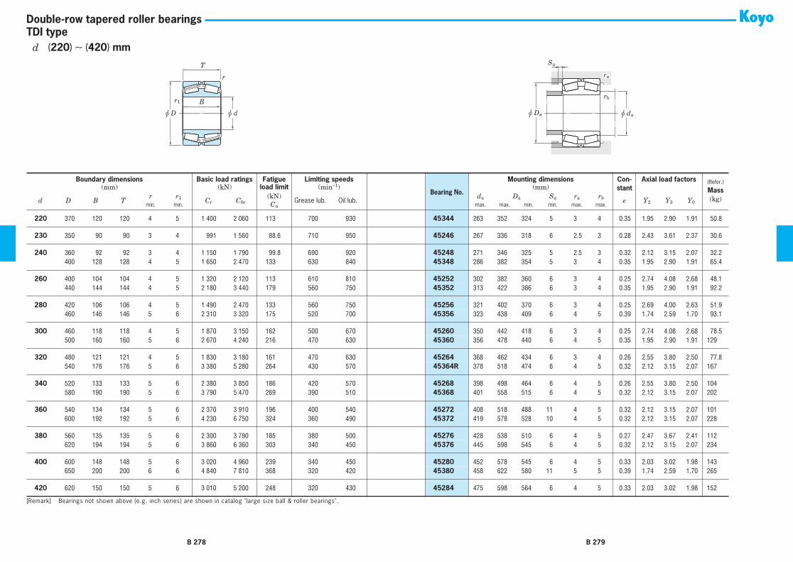
r
u d
B
u D
T
r1
u dau Da
Sa
rb
ra
TDI typeDouble-row tapered roller bearings
220
370 120 120 4 5 1 400 2 060 113 700 930
45344
263 352 324 5 3 4 0.35 1.95 2.90 1.91 50.8
230
350 90 90 3 4 991 1 560 88.6 710 950
45246
267 336 318 6 2.5 3 0.28 2.43 3.61 2.37 30.6
240
360 92 92 3 4 1 150 1 790 99.8 690 920
45248
271 346 325 5 2.5 3 0.32 2.12 3.15 2.07 32.2
240
400 128 128 4 5 1 650 2 470 133 630 840
45348
286 382 354 5 3 4 0.35 1.95 2.90 1.91 65.4
260
400 104 104 4 5 1 320 2 120 113 610 810
45252
302 382 360 6 3 4 0.25 2.74 4.08 2.68 48.1
260
440 144 144 4 5 2 180 3 440 179 560 750
45352
313 422 386 6 3 4 0.35 1.95 2.90 1.91 92.2
280
420 106 106 4 5 1 490 2 470 133 560 750
45256
321 402 370 6 3 4 0.25 2.69 4.00 2.63 51.9
280
460 146 146 5 6 2 310 3 320 175 520 700
45356
323 438 409 6 4 5 0.39 1.74 2.59 1.70 93.1
300
460 118 118 4 5 1 870 3 150 162 500 670
45260
350 442 418 6 3 4 0.25 2.74 4.08 2.68 78.5
300
500 160 160 5 6 2 670 4 240 216 470 630
45360
356 478 440 6 4 5 0.35 1.95 2.90 1.91 129
320
480 121 121 4 5 1 830 3 180 161 470 630
45264
368 462 434 6 3 4 0.26 2.55 3.80 2.50 77.8
320
540 176 176 5 6 3 380 5 280 264 430 570
45364R
378 518 474 6 4 5 0.32 2.12 3.15 2.07 167
340
520 133 133 5 6 2 380 3 850 186 420 570
45268
398 498 464 6 4 5 0.26 2.55 3.80 2.50 104
340
580 190 190 5 6 3 790 5 470 269 390 510
45368
401 558 515 6 4 5 0.32 2.12 3.15 2.07 202
360
540 134 134 5 6 2 370 3 910 196 400 540
45272
408 518 488 11 4 5 0.32 2.12 3.15 2.07 101
360
600 192 192 5 6 4 230 6 750 324 360 490
45372
419 578 528 10 4 5 0.32 2.12 3.15 2.07 228
380
560 135 135 5 6 2 300 3 790 185 380 500
45276
428 538 510 6 4 5 0.27 2.47 3.67 2.41 112
380
620 194 194 5 6 3 860 6 360 303 340 450
45376
445 598 545 6 4 5 0.32 2.12 3.15 2.07 234
400
600 148 148 5 6 3 020 4 960 239 340 450
45280
452 578 545 6 4 5 0.33 2.03 3.02 1.98 143
400
650 200 200 6 6 4 840 7 810 368 320 420
45380
458 622 580 11 5 5 0.39 1.74 2.59 1.70 265
420
620 150 150 5 6 3 010 5 200 248 320 430
45284
475 598 564 6 4 5 0.33 2.03 3.02 1.98 152
Boundary dimensions Basic load ratings Fatigue Limiting speeds
Bearing No.
Mounting dimensions Con-stant
Axial load factors
(Refer.)
Mass
(kg)
(mm) (kN)
load limit
(min
−
1
) (mm)
d D B Tr r
1
C
r
C
0r
(kN)
Grease lub. Oil lub.
d
a
D
a
S
a
r
a
r
b
e Y
2
Y
3
Y
0
min. min.
C
u
max. max. min. min. max. max.
[Remark] Bearings not shown above (e.g. inch series) are shown in catalog "large size ball & roller bearings".
B 278 B 279
d
(
220
)
∼
(
420
)
mm

r
u d
B
u D
T
r1
u dau Da
Sa
rb
ra
TDI typeDouble-row tapered roller bearings
420
700 224 224 6 6 5 430 8 380 389 280 380
45384
488 672 623 7 5 5 0.39 1.74 2.59 1.70 352
440
650 157 157 6 6 3 190 5 500 256 300 390
45288
500 622 592 10 5 5 0.28 2.43 3.61 2.37 182
440
720 226 226 6 6 5 750 9 130 417 270 360
45388
506 692 642 7 5 5 0.39 1.74 2.59 1.70 367
460
680 163 163 6 6 3 480 5 660 265 280 370
45292
510 652 616 6 5 5 0.39 1.74 2.59 1.70 197
460
760 240 240 7.5 7.5 6 570 10 400 463 250 330
45392
532 724 677 7 6 6 0.39 1.74 2.59 1.70 444
480
700 165 165 6 6 3 830 6 710 307 260 350
45296
531 672 625 6 5 5 0.40 1.68 2.50 1.64 215
500
720 167 167 6 6 4 300 7 350 340 250 330
452/500
545 692 645 8 5 5 0.39 1.74 2.59 1.70 222
500
830 264 264 7.5 7.5 7 970 12 300 555 210 280
453/500
587 794 729 7 6 6 0.33 2.03 3.02 1.98 586
Boundary dimensions Basic load ratings Fatigue Limiting speeds
Bearing No.
Mounting dimensions Con-stant
Axial load factors
(Refer.)
Mass
(kg)
(mm) (kN)
load limit
(min
−
1
) (mm)
d D B Tr r
1
C
r
C
0r
(kN)
Grease lub. Oil lub.
d
a
D
a
S
a
r
a
r
b
e Y
2
Y
3
Y
0
min. min.
C
u
max. max. min. min. max. max.
[Remark] Bearings not shown above (e.g. inch series) are shown in catalog "large size ball & roller bearings".
B 280 B 281
d
(
420
)
∼
500 mm

B 282 B 283
Spherical roller bearings Spherical roller bearings
Adapter assemblies
Withdrawal sleeves
Bore diameter 25 – 500 mm
Bore diameter 20 – 470 mm
Bore diameter 35 – 480 mm
Cylindrical bore Tapered boreSpherical roller bearings feature a large load rating capacity and self-aligning capability.
This type of bearing is suitable for low- or medium-speed applications which involve heavy or impact loading.
*These bearings are divided into R(RR), RH(RHR)and RHA types, which differ in internal structure.(refer to Table 1.)*Each type can be produced with a cylindrical bore or
tapered bore.Bearings with a tapered bore can be fit and removed
easily using an adapter assembly or withdrawal sleeve.The rate of taper is equivalent among all bearing series.240 and 241 series ... 1 : 30 (supplementary code "K30")
Others ... 1 : 12 (supplementary code "K")
Table 1 Spherical roller bearings : types and structures
Structure
R, RR type RH, RHR type RHA type
Roller Convex asymmetrical roller Convex symmetrical roller Convex symmetrical roller
Cage Copper alloy prong typemachined cage
Pressed steelcage
Copper alloy integraltype machined cage
Inner ring(with orwithout rib)
With center ribWithout center rib
(guide ring)Without center rib
(guide ring)
With ribs on both sides(to prevent rollers from falling)
Without ribs onboth sides
With ribs on both sides(to prevent rollers from falling)
Characteristics Superior to RH, RHR and RHA types in high-speed performance.
The load rating capacity is larger than that of R and RR type.(There are some exceptional cases due to different interior specifications.)
■ Spherical roller bearings for shaker screens*These bearings consist of convex asymmetric rollers and a
prong type, copper alloy, outer ring guided, machined cage. This cage possesses optimum characteristics for use with shaker screens.*The bearings most commonly used with shaker screens
are 223 series spherical roller bearings.They are identified by the supplementary code "ROVS W502." The outer ring outside diameter tolerance of these bearings is held to a small allowable variation.

B 284 B 285
ud0
w
h
■ Bearings with lubrication holes and a lubrication groove*Outer rings can be provided with lubrication
holes, a lubrication groove and an anti-rotation pin hole. (Specifications are given in Table 4.)
Table 2 Supplementary codes for identification ofbearings with lubrication holes, lubricationgroove and anti-rotation pin hole (outer ring)
Supplementary code Number of lubri- cation holes
Hole layout
With lubrication holes and lubri- cation groove
With lubrication holes, lubrication groove and anti- rotation pin hole
W33 W3N 31) 3 equally spaced positions1)
W33A W3NA 4 4 equally spaced positions
− W3NB 5 6 equally spaced positions2)
W33C W3NC 6 6 equally spaced positions
− W3ND 7 8 equally spaced positions2)
W33T − 8 8 equally spaced positions
*Inner rings can also be provided with lubrica-tion holes and a lubrication groove.
Table 3 Supplementary codes for identificationof bearings with lubrication holes and/or lubrication groove
Supplemen- tary code
Inner ring Outer ring
Numberof lubri-cationholes
Lubri-cationgroove
Numberof lubri-cationholes
Lubri-cationgroove
W513 3 − 3 # W518 3 − 3 − W26 3 − − −
[Notes] 1) Also 4 or 6 holes are provided in smaller size bearings, consult with JTEKT.2) One hole is used for the antirotation pin.
[Remark] Boldfaced codes indicate JTEKT standards.
Table 4 (2) Lubrication hole and lubrication groove dimensions Unit : mm
Borediameternumber
Nominalborediameter
d
239 230 240 231 241 222 232 213 223
d0 w h d0 w h d0 w h d0 w h d0 w h d0 w h d0 w h d0 w h d0 w h
76 380 12 14 3 14 16.5 4 14 16.5 3 14 16.5 4 14 16.5 4 − − − 14 16.5 4 − − − − − − 80 400 12 14 3 14 16.5 4 14 16.5 4 14 16.5 4 14 16.5 4 − − − 14 16.5 4 − − − − − − 84 420 12 14 3 14 16.5 4 14 16.5 4 14 16.5 4 14 16.5 4 − − − 14 16.5 4 − − − − − − 88 440 14 16.5 4 14 16.5 4 14 16.5 4 14 16.5 4 14 16.5 4 − − − 14 16.5 4 − − − − − − 92 460 14 16.5 4 14 16.5 4 14 16.5 4 14 16.5 4 14 16.5 4 − − − 14 16.5 4 − − − − − − 96 480 14 16.5 4 14 16.5 4 14 16.5 4 14 16.5 4 14 16.5 4 − − − 14 16.5 4 − − − − − −/500 500 14 16.5 4 14 16.5 4 14 16.5 4 14 16.5 4 14 16.5 5 − − − 14 16.5 4 − − − − − −
Boundary dimensions As specified in JIS B 1512.
TolerancesAs specified in JIS B 1514-1, class 0. (refer to Table 7-3 on pp. A 60 − A 63.)Refer to Table 7-11 on p. A 76 for the tolerance of tapered bores.
Radial internal clearance As specified in JIS B 1520. (refer to Table 10-9 on p. A 108.)
Recommended fits Refer to Table 9-4 on pp. A 91, 92.
Standard cages Refer to Table 5.
Allowable aligning angle Refer to Table 5. (varies depending on bearing series.)
Equivalent radial load Dynamic equivalent radial load
[Note] Refer to the specification table for the values of axial load factors Y1, Y2 and Y0 and of constant e.
Static equivalent radial load P0r = Fr + Y0 Fa
When Pr = Fr + Y1 Fa ² eFaFr
When Pr = 0.67Fr + Y2 Fa > eFaFr
[Remark] If the ratio of axial load to radial load exceeds the value e given in the specification table (Fa / Fr > e),slippage occurs between rollers in rows that are not axial-loaded and the raceway.This may cause smearing, especially when the bearing is large. Consult with JTEKT on the use of bear-ings under such conditions.
Table 5 Application of standard cages and allowable aligning angle
Bearing seriesStandard cages Allowable aligning
anglePressed cage Machined cage239 R ⎯⎯ 23930R − 239/500R 0.026 rad (1.5°)230 R
RHRHA
⎯⎯23022RH − 23036RH
⎯⎯
23038R − 230/500R⎯⎯
23038RHA − 23096RHA
0.026 rad (1.5°)
240 R(RR)RHRHA
⎯⎯24024RH − 24034RH
⎯⎯
24036R − 240/500R⎯⎯
24038RHA − 24096RHA
0.035 rad (2°)
231 RRHRHA
⎯⎯23122RH − 23134RH
⎯⎯
23136R − 231/500R⎯⎯
23136RHA − 23196RHA
0.026 rad (1.5°)
241 R(RR)RHRHA
⎯⎯24122RH − 24130RH
⎯⎯
24132R − 241/500R⎯⎯
24136RHA − 24196RHA
0.044 rad (2.5°)
222 R(RR)RH(RHR)RHA
⎯⎯22205RHR − 22230RH
⎯⎯
22232RR − 22272R⎯⎯
22232RHA − 22260RHA
0.026 rad (1.5°)
232 RRHRHA
⎯⎯23218RH − 23230RH
⎯⎯
23232R − 232/500R⎯⎯
23232RHA − 23296RHA
0.044 rad (2.5°)
213 RRH
⎯⎯21311RH − 21322RH
21322R − 21328R⎯⎯
0.017 rad (1°)
223 R(RR)RH(RHR)RHA
⎯⎯22308RHR − 22326RH
⎯⎯
22328R − 22360R⎯⎯
22328RHA − 22356RHA
0.035 rad (2°)
Table 4 (1) Lubrication hole and lubrication groove dimensions Unit : mm
Borediameternumber
Nominalborediameter
d
239 230 240 231 241 222 232 213 223
d0 w h d0 w h d0 w h d0 w h d0 w h d0 w h d0 w h d0 w h d0 w h
5 25 − − − − − − − − − − − − − − − 3 4 0.7 − − − − − − − − − 6 30 − − − − − − − − − − − − − − − 3 4 0.7 − − − 3 4 0.7 − − − 7 35 − − − − − − − − − − − − − − − 3 4 0.8 − − − 3 4 0.7 3 4 1 8 40 − − − − − − − − − − − − − − − 3 4 0.8 − − − 3 4 0.7 4 5 1 9 45 − − − − − − − − − − − − − − − 3 4 0.8 − − − 3 4 0.7 4 6 1 10 50 − − − − − − − − − − − − − − − 3 4 0.8 − − − 3 4 0.7 4 6 1 11 55 − − − − − − − − − − − − − − − 3 4 0.8 − − − 3 4 0.7 4 6 1.1 12 60 − − − − − − − − − − − − − − − 3 4 1 − − − 3 4 1 4 6 1.1 13 65 − − − − − − − − − − − − − − − 3 4 1 − − − 3 4 1 4 6 1.2 14 70 − − − − − − − − − − − − − − − 3 4 1 − − − 3 4 1 5 7 1.3 15 75 − − − − − − − − − − − − − − − 3 4 1 − − − 3 4 1 5 7 1.3 16 80 − − − − − − − − − − − − − − − 3 4 1 4 6 1.2 4 6 1 5 7 1.3 17 85 − − − − − − − − − − − − − − − 4 5 1 4 6 1.2 4 6 1.2 6 8 1.3 18 90 − − − − − − − − − − − − − − − 4 5 1 5 8 1.2 4 6 1.2 6 8 1.3 19 95 − − − − − − − − − − − − − − − 5 6 1.2 5 8 1.2 4 6 1.2 6 8 2 20 100 − − − 4 5 1 − − − 5 6 1.4 − − − 5 6 1.2 5 8 1.2 4 6 1.2 6 8 2 22 110 − − − 5 7 1 − − − 5 6 1.4 6 8 1.5 5 7 1.5 6 8 1.7 4 6 1.2 6 8 2 24 120 − − − 5 7 1 5 6 1.4 5 6 1.4 6 8 1.5 5 7 1.5 6 10 1.7 − − − 8 10 2.5 26 130 − − − 5 7 1.2 6 8 1.5 5 6 1.5 6 8 1.5 5 7 1.5 6 10 1.7 − − − 8 12 2.5 28 140 4 5 1 5 7 1.2 6 8 1.5 6 8 1.5 8 10 2 6 8 1.8 8 10 2.5 − − − 12 14 3 30 150 5 7 1 5 8 1.2 6 8 1.5 6 10 1.5 8 10 2 6 10 1.8 8 10 2.5 − − − 12 14 3 32 160 5 7 1.2 5 8 1.2 6 8 1.5 8 12 2 10 12 2 10 12 2.5 10 12 2.5 − − − 12 14 3 34 170 5 7 1.2 6 10 1.5 8 10 2 8 12 2 10 12 2 12 14 3 10 12 2.5 − − − 12 14 3 36 180 6 7 1.3 8 12 1.5 10 12 2.5 10 12 2.5 10 12 2 12 14 3 10 12 2.5 − − − 14 16.5 4 38 190 5 7 1.2 10 12 2.5 10 12 2.5 10 12 2.5 10 12 2 12 14 3 12 14 3 − − − 14 16.5 4 40 200 6 8 1.5 10 12 2.5 10 12 2.5 12 14 3 12 14 3 12 14 3 12 14 3 − − − 14 16.5 4 44 220 6 8 1.5 10 12 2.5 10 12 2.5 12 14 3 12 14 3 12 14 3 12 14 3 − − − 14 16.5 4 48 240 6 8 1.5 10 12 2.5 10 12 2.5 12 14 3 12 14 3 14 16.5 4 14 16.5 4 − − − 14 16.5 4 52 260 10 12 2.5 12 14 3 12 14 3 12 14 3 12 14 3 14 16.5 4 14 16.5 4 − − − 14 16.5 4 56 280 10 12 2.5 12 14 3 12 14 3 12 14 3 12 14 3 14 16.5 4 14 16.5 4 − − − 14 16.5 4 60 300 10 12 2.5 12 14 3 12 14 3 12 14 3 12 14 3 14 16.5 4 14 16.5 4 − − − 14 16.5 4 64 320 10 12 2.5 12 14 3 12 14 3 14 16.5 4 14 16.5 4 14 16.5 4 14 16.5 4 − − − 14 16.5 4 68 340 12 14 3 14 16.5 4 14 16.5 3 14 16.5 4 14 16.5 4 14 16.5 4 14 16.5 4 − − − 14 16.5 4 72 360 12 14 3 14 16.5 4 14 16.5 3 14 16.5 4 14 16.5 4 14 16.5 4 14 16.5 4 − − − 14 16.5 4
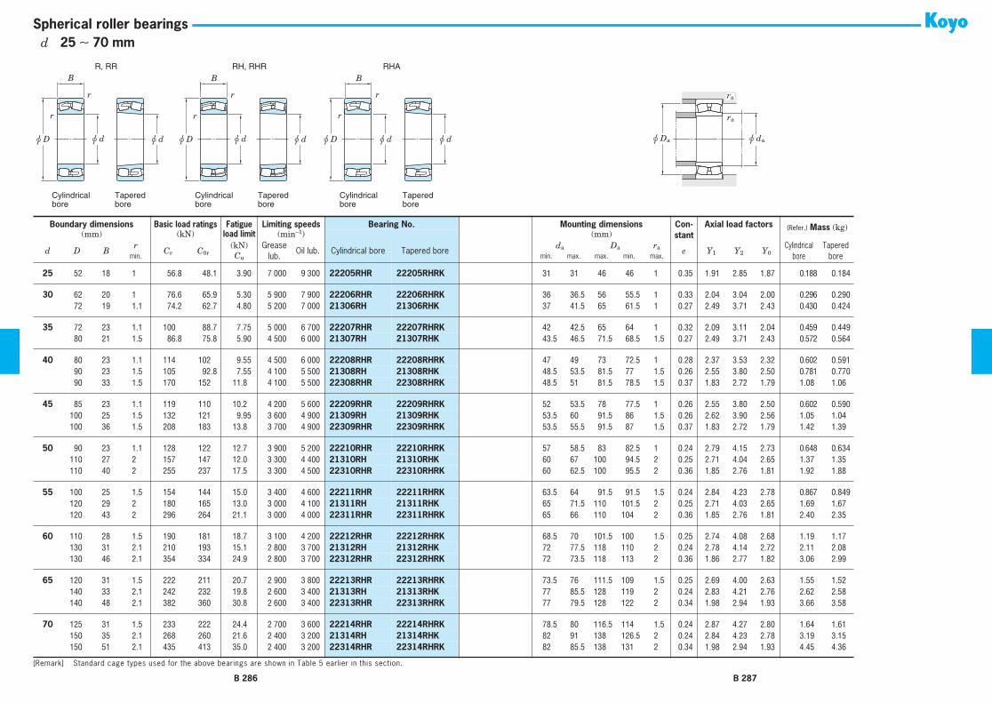
R, RR RH, RHR RHA
Cylindricalbore
Taperedbore
Cylindricalbore
Taperedbore
Cylindricalbore
Taperedbore
r
r
r
r
B B
r
r
B
u d u du D u d u du D u d u du D u Da u da
ra
ra
Spherical roller bearings
Boundary dimensions
Basic load ratings Fatigue
Limiting speeds Bearing No. Mounting dimensions Con-stant
Axial load factors
(Refer.)
Mass
(kg)(mm) (kN)
load limit
(min
−
1
) (mm)
d D Br
C
r
C
0r
(kN)
Greaselub.
Oil lub. Cylindrical bore Tapered bore
d
a
D
a
r
a
e Y
1
Y
2
Y
0
Cylindricalbore
Taperedboremin.
C
u
min. max. max. min. max.
25
52 18 1 56.8 48.1 3.90 7 000 9 300
22205RHR 22205RHRK
31 31 46 46 1 0.35 1.91 2.85 1.87 0.188 0.184
30
62 20 1 76.6 65.9 5.30 5 900 7 900
22206RHR 22206RHRK
36 36.5 56 55.5 1 0.33 2.04 3.04 2.00 0.296 0.290
30
72 19 1.1 74.2 62.7 4.80 5 200 7 000
21306RH 21306RHK
37 41.5 65 61.5 1 0.27 2.49 3.71 2.43 0.430 0.424
35
72 23 1.1 100 88.7 7.75 5 000 6 700
22207RHR 22207RHRK
42 42.5 65 64 1 0.32 2.09 3.11 2.04 0.459 0.449
35
80 21 1.5 86.8 75.8 5.90 4 500 6 000
21307RH 21307RHK
43.5 46.5 71.5 68.5 1.5 0.27 2.49 3.71 2.43 0.572 0.564
40
80 23 1.1 114 102 9.55 4 500 6 000
22208RHR 22208RHRK
47 49 73 72.5 1 0.28 2.37 3.53 2.32 0.602 0.591
40
90 23 1.5 105 92.8 7.55 4 100 5 500
21308RH 21308RHK
48.5 53.5 81.5 77 1.5 0.26 2.55 3.80 2.50 0.781 0.770
40
90 33 1.5 170 152 11.8 4 100 5 500
22308RHR 22308RHRK
48.5 51 81.5 78.5 1.5 0.37 1.83 2.72 1.79 1.08 1.06
45
85 23 1.1 119 110 10.2 4 200 5 600
22209RHR 22209RHRK
52 53.5 78 77.5 1 0.26 2.55 3.80 2.50 0.602 0.590
45
100 25 1.5 132 121 9.95 3 600 4 900
21309RH 21309RHK
53.5 60 91.5 86 1.5 0.26 2.62 3.90 2.56 1.05 1.04
45
100 36 1.5 208 183 13.8 3 700 4 900
22309RHR 22309RHRK
53.5 55.5 91.5 87 1.5 0.37 1.83 2.72 1.79 1.42 1.39
50
90 23 1.1 128 122 12.7 3 900 5 200
22210RHR 22210RHRK
57 58.5 83 82.5 1 0.24 2.79 4.15 2.73 0.648 0.634
50
110 27 2 157 147 12.0 3 300 4 400
21310RH 21310RHK
60 67 100 94.5 2 0.25 2.71 4.04 2.65 1.37 1.35
50
110 40 2 255 237 17.5 3 300 4 500
22310RHR 22310RHRK
60 62.5 100 95.5 2 0.36 1.85 2.76 1.81 1.92 1.88
55
100 25 1.5 154 144 15.0 3 400 4 600
22211RHR 22211RHRK
63.5 64 91.5 91.5 1.5 0.24 2.84 4.23 2.78 0.867 0.849
55
120 29 2 180 165 13.0 3 000 4 100
21311RH 21311RHK
65 71.5 110 101.5 2 0.25 2.71 4.03 2.65 1.69 1.67
55
120 43 2 296 264 21.1 3 000 4 000
22311RHR 22311RHRK
65 66 110 104 2 0.36 1.85 2.76 1.81 2.40 2.35
60
110 28 1.5 190 181 18.7 3 100 4 200
22212RHR 22212RHRK
68.5 70 101.5 100 1.5 0.25 2.74 4.08 2.68 1.19 1.17
60
130 31 2.1 210 193 15.1 2 800 3 700
21312RH 21312RHK
72 77.5 118 110 2 0.24 2.78 4.14 2.72 2.11 2.08
60
130 46 2.1 354 334 24.9 2 800 3 700
22312RHR 22312RHRK
72 73.5 118 113 2 0.36 1.86 2.77 1.82 3.06 2.99
65
120 31 1.5 222 211 20.7 2 900 3 800
22213RHR 22213RHRK
73.5 76 111.5 109 1.5 0.25 2.69 4.00 2.63 1.55 1.52
65
140 33 2.1 242 232 19.8 2 600 3 400
21313RH 21313RHK
77 85.5 128 119 2 0.24 2.83 4.21 2.76 2.62 2.58
65
140 48 2.1 382 360 30.8 2 600 3 400
22313RHR 22313RHRK
77 79.5 128 122 2 0.34 1.98 2.94 1.93 3.66 3.58
70
125 31 1.5 233 222 24.4 2 700 3 600
22214RHR 22214RHRK
78.5 80 116.5 114 1.5 0.24 2.87 4.27 2.80 1.64 1.61
70
150 35 2.1 268 260 21.6 2 400 3 200
21314RH 21314RHK
82 91 138 126.5 2 0.24 2.84 4.23 2.78 3.19 3.15
70
150 51 2.1 435 413 35.0 2 400 3 200
22314RHR 22314RHRK
82 85.5 138 131 2 0.34 1.98 2.94 1.93 4.45 4.36
[Remark] Standard cage types used for the above bearings are shown in Table 5 earlier in this section.
B 286 B 287
d
25
∼
70 mm

R, RR RH, RHR RHA
Cylindricalbore
Taperedbore
Cylindricalbore
Taperedbore
Cylindricalbore
Taperedbore
r
r
r
r
B B
r
r
B
u d u du D u d u du D u d u du D u Da u da
ra
ra
Spherical roller bearings
75
130 31 1.5 241 236 28.2 2 600 3 400
22215RHR 22215RHRK
83.5 85.5 121.5 119 1.5 0.22 3.07 4.57 3.00 1.73 1.69
75
160 37 2.1 306 298 24.3 2 200 3 000
21315RH 21315RHK
87 98 148 138 2 0.24 2.87 4.27 2.80 3.81 3.76
75
160 55 2.1 492 473 38.4 2 200 3 000
22315RHR 22315RHRK
87 91 148 139.5 2 0.35 1.95 2.90 1.91 5.45 5.33
80
140 33 2 271 271 30.5 2 400 3 200
22216RHR 22216RHRK
90 92 130 128 2 0.22 3.07 4.57 3.00 2.17 2.13
80
170 39 2.1 344 339 27.5 2 100 2 800
21316RH 21316RHK
92 104 158 146 2 0.23 2.88 4.29 2.82 4.53 4.47
80
170 58 2.1 539 521 41.7 2 100 2 800
22316RHR 22316RHRK
92 97 158 148 2 0.35 1.95 2.90 1.91 6.44 6.30
85
150 36 2 322 324 35.7 2 200 3 000
22217RHR 22217RHRK
95 97 140 137 2 0.22 3.01 4.48 2.94 2.75 2.69
85
180 41 3 374 372 29.6 2 000 2 600
21317RH 21317RHK
99 109 166 154 2.5 0.23 2.89 4.33 2.83 5.32 5.25
85
180 60 3 601 586 47.8 2 000 2 600
22317RHR 22317RHRK
99 103 166 157 2.5 0.33 2.02 3.00 1.97 7.47 7.31
90
160 40 2 372 381 39.2 2 100 2 800
22218RHR 22218RHRK
100 104 150 145 2 0.24 2.79 4.15 2.73 3.50 3.43
90
160 52.4 2 421 482 42.9 2 100 2 800
23218RH 23218RHK
100 103 150 141 2 0.32 2.14 3.19 2.09 4.63 4.50
90
190 43 3 413 416 32.9 1 900 2 500
21318RH 21318RHK
104 116 176 162 2.5 0.23 2.91 4.30 2.84 6.20 6.11
90
190 64 3 672 662 50.5 1 900 2 500
22318RHR 22318RHRK
104 108 176 166 2.5 0.34 2.00 2.98 1.96 8.82 8.63
95
170 43 2.1 417 422 42.7 2 000 2 600
22219RHR 22219RHRK
107 109 158 154 2 0.24 2.76 4.11 2.70 4.24 4.15
95
200 45 3 452 461 36.3 1 800 2 300
21319RH 21319RHK
109 123 186 171 2.5 0.23 2.92 4.35 2.86 7.16 7.06
95
200 67 3 733 726 55.6 1 800 2 300
22319RHR 22319RHRK
109 114 186 174 2.5 0.33 2.02 3.00 1.97 10.2 9.98
100
150 37 1.5 262 332 33.7 2 100 2 800
23020RH 23020RHK
117 110 141 138 1.5 0.22 3.01 4.48 2.94 2.34 2.27
100
180 46 2.1 470 481 47.6 1 900 2 500
22220RHR 22220RHRK
112 115 168 163 2 0.25 2.74 4.08 2.68 5.11 5.00
100
180 60.3 2.1 533 629 53.5 1 900 2 500
23220RH 23220RHK
112 116 168 157 2 0.32 2.09 3.11 2.04 6.85 6.66
100
215 47 3 519 524 40.2 1 600 2 200
21320RH 21320RHK
114 131 201 184 2.5 0.22 3.02 4.49 2.95 8.79 8.68
100
215 73 3 875 877 63.9 1 600 2 200
22320RHR 22320RHRK
114 121 201 187 2.5 0.35 1.95 2.90 1.91 13.2 12.9
110
170 45 2 377 486 48.4 1 900 2 500
23022RH 23022RHK
120 123 160 156 2 0.24 2.84 4.23 2.78 3.85 3.74
110
180 56 2 484 605 53.7 1 800 2 400
23122RH 23122RHK
120 125 170 161 2 0.29 2.36 3.51 2.31 5.72 5.54
110
180 69 2 569 778 63.4 1 800 2 400
24122RH 24122RHK30
120 120 170 154 2 0.37 1.84 2.74 1.80 6.98 6.87
110
200 53 2.1 612 642 58.7 1 700 2 200
22222RHR 22222RHRK
122 127 188 180 2 0.26 2.64 3.93 2.58 7.37 7.21
110
200 69.8 2.1 672 792 65.4 1 700 2 200
23222RH 23222RHK
122 127 188 173 2 0.34 1.99 2.96 1.94 9.76 9.48
110
240 50 3 604 616 46.0 1 400 1 900
21322RH 21322RHK
124 147 226 205 2.5 0.21 3.19 4.75 3.12 11.8 11.7
Boundary dimensions
Basic load ratings Fatigue
Limiting speeds Bearing No. Mounting dimensions Con-stant
Axial load factors
(Refer.)
Mass
(kg)(mm) (kN)
load limit
(min
−
1
) (mm)
d D Br
C
r
C
0r
(kN)
Greaselub.
Oil lub. Cylindrical bore Tapered bore
d
a
D
a
r
a
e Y
1
Y
2
Y
0
Cylindricalbore
Taperedboremin.
C
u
min. max. max. min. max.
[Remark] Standard cage types used for the above bearings are shown in Table 5 earlier in this section.
B 288 B 289
d
75
∼
(
110
)
mm

R, RR RH, RHR RHA
Cylindricalbore
Taperedbore
Cylindricalbore
Taperedbore
Cylindricalbore
Taperedbore
r
r
r
r
B B
r
r
B
u d u du D u d u du D u d u du D u Da u da
ra
ra
Spherical roller bearings
110
240 80 3 1 040 1 040 77.7 1 400 1 900
22322RHR 22322RHRK
124 136 226 208 2.5 0.33 2.03 3.02 1.98 18.1 17.7
120
180 46 2 394 524 51.6 1 700 2 300
23024RH 23024RHK
130 132 170 165 2 0.23 2.95 4.40 2.89 4.20 4.07
120
180 60 2 484 709 61.8 1 700 2 300
24024RH 24024RHK30
130 130 170 160 2 0.30 2.23 3.32 2.18 5.43 5.34
120
200 62 2 571 714 61.2 1 600 2 200
23124RH 23124RHK
130 137 190 176 2 0.29 2.34 3.49 2.29 7.98 7.74
120
200 80 2 733 1 020 78.6 1 600 2 200
24124RH 24124RHK30
130 133 190 172 2 0.38 1.75 2.61 1.72 10.2 10.0
120
215 58 2.1 706 764 67.2 1 500 2 000
22224RHR 22224RHRK
132 138 203 193 2 0.26 2.60 3.87 2.54 9.31 9.10
120
215 76 2.1 772 956 78.9 1 500 2 100
23224RH 23224RHK
132 139 203 185 2 0.34 1.97 2.94 1.93 12.2 11.8
120
260 86 3 1 120 1 130 87.2 1 300 1 800
22324RHR 22324RHRK
134 149 246 228 2.5 0.33 2.03 3.02 1.98 22.8 22.3
130
200 52 2 509 674 63.6 1 600 2 100
23026RH 23026RHK
140 145 190 182 2 0.24 2.87 4.27 2.80 6.15 5.97
130
200 69 2 625 914 77.3 1 600 2 100
24026RH 24026RHK30
140 143 190 177 2 0.32 2.14 3.18 2.09 8.03 7.90
130
210 64 2 621 799 68.4 1 500 2 000
23126RH 23126RHK
140 147 200 187 2 0.28 2.42 3.61 2.37 8.71 8.44
130
210 80 2 754 1 080 91.8 1 500 2 000
24126RH 24126RHK30
140 145 200 184 2 0.36 1.90 2.83 1.86 10.8 10.6
130
230 64 3 821 914 74.4 1 400 1 900
22226RHR 22226RHRK
144 148 216 206 2.5 0.26 2.55 3.80 2.50 11.6 11.3
130
230 80 3 880 1 090 89.4 1 400 1 900
23226RH 23226RHK
144 151 216 201 2.5 0.33 2.05 3.05 2.00 14.4 14.0
130
280 93 4 1 310 1 340 98.6 1 200 1 600
22326RHR 22326RHRK
148 160 262 245 3 0.33 2.03 3.02 1.98 28.5 27.9
140
210 53 2 530 723 67.9 1 500 2 000
23028RH 23028RHK
150 155 200 192 2 0.23 2.98 4.44 2.92 6.62 6.42
140
210 69 2 640 957 81.7 1 500 2 000
24028RH 24028RHK30
150 153 200 188 2 0.30 2.28 3.39 2.23 8.49 8.35
140
225 68 2.1 710 940 79.6 1 400 1 900
23128RH 23128RHK
152 158 213 201 2 0.28 2.45 3.65 2.40 10.6 10.3
140
225 85 2.1 853 1 220 90.7 1 400 1 900
24128RH 24128RHK30
152 153 213 194 2 0.36 1.89 2.82 1.85 13.1 12.9
140
250 68 3 947 1 030 85.2 1 300 1 700
22228RHR 22228RHRK
154 158 236 224 2.5 0.26 2.60 3.87 2.54 14.5 14.2
140
250 88 3 1 020 1 290 103 1 300 1 700
23228RH 23228RHK
154 161 236 214 2.5 0.34 1.99 2.96 1.95 19.0 18.4
140
300 102 4 1 470 1 570 105 1 100 1 500
22328RH 22328RHK
158 172 282 255 3 0.35 1.95 2.90 1.90 35.7 34.9
150 210 45 2 418 622 62.5 1 600 2 100 23930R 23930RK 160 170 200 195 2 0.20 3.44 5.12 3.36 5.09 4.93150 225 56 2.1 579 797 76.3 1 400 1 800 23030RH 23030RHK 162 166 213 205 2 0.22 3.04 4.53 2.97 8.01 7.77150 225 75 2.1 724 1 100 90.3 1 400 1 800 24030RH 24030RHK30 162 163 213 199 2 0.30 2.23 3.32 2.18 10.6 10.4
150 250 80 2.1 902 1 230 102 1 300 1 700 23130RH 23130RHK 162 171 238 216 2 0.30 2.24 3.34 2.19 16.4 15.9150 250 100 2.1 1 110 1 590 116 1 300 1 700 24130RH 24130RHK30 162 166 238 213 2 0.38 1.77 2.64 1.73 19.9 19.6
Boundary dimensions Basic load ratings Fatigue Limiting speeds Bearing No. Mounting dimensions Con-stant
Axial load factors (Refer.) Mass (kg)(mm) (kN) load limit (min−1) (mm)
d D Br
Cr C0r(kN) Grease
lub.Oil lub. Cylindrical bore Tapered bore
da Da ra e Y1 Y2 Y0Cylindrical
boreTapered
boremin. Cu min. max. max. min. max.
[Remark] Standard cage types used for the above bearings are shown in Table 5 earlier in this section.
B 290 B 291
d (110) ∼ (150) mm

R, RR RH, RHR RHA
Cylindricalbore
Taperedbore
Cylindricalbore
Taperedbore
Cylindricalbore
Taperedbore
r
r
r
r
B B
r
r
B
u d u du D u d u du D u d u du D u Da u da
ra
ra
Spherical roller bearings
150 270 73 3 1 080 1 200 102 1 200 1 600 22230RHR 22230RHRK 164 172 256 243 2.5 0.25 2.69 4.00 2.63 18.9 18.5150 270 96 3 1 200 1 540 121 1 200 1 600 23230RH 23230RHK 164 173 256 230 2.5 0.34 1.96 2.93 1.92 24.5 23.8150 320 108 4 1 540 1 600 175 1 200 1 500 22330R 22330RK 168 195 302 273 3 0.38 1.78 2.64 1.74 43.6 42.7
150 320 108 4 1 620 1 740 121 1 200 1 500 22330RHA 22330RHAK 168 196 302 273 3 0.35 1.93 2.87 1.88 40.3 39.4
160 220 45 2 426 649 65.4 1 500 2 000 23932R 23932RK 170 179 210 204 2 0.19 3.60 5.37 3.52 5.37 5.20160 240 60 2.1 667 924 86.0 1 300 1 700 23032RH 23032RHK 172 177 228 219 2 0.22 3.01 4.48 2.94 9.74 9.44160 240 80 2.1 829 1 270 103 1 300 1 700 24032RH 24032RHK30 172 175 228 215 2 0.30 2.24 3.34 2.19 12.9 12.7
160 270 86 2.1 1 070 1 430 117 1 200 1 600 23132RH 23132RHK 172 182 258 234 2 0.30 2.22 3.30 2.17 20.8 20.2160 270 109 2.1 1 270 1 720 145 1 700 1 300 24132RR 24132RRK30 172 188 258 230 2 0.39 1.72 2.56 1.68 25.9 25.5160 290 80 3 1 110 1 270 127 1 200 1 600 22232R 22232RK 174 199 276 257 2.5 0.28 2.40 3.57 2.35 23.4 22.9
160 290 80 3 1 120 1 320 97.1 1 200 1 600 22232RHA 22232RHAK 174 200 276 257 2.5 0.27 2.49 3.71 2.44 21.9 21.4160 290 104 3 1 290 1 650 163 1 200 1 600 23232R 23232RK 174 194 276 245 2.5 0.38 1.79 2.66 1.75 31.0 30.1160 290 104 3 1 370 1 780 139 1 200 1 600 23232RHA 23232RHAK 174 193 276 245 2.5 0.36 1.87 2.78 1.83 29.4 28.5
160 340 114 4 1 720 1 790 188 1 100 1 400 22332R 22332RK 178 207 322 290 3 0.38 1.76 2.62 1.72 51.9 51.0160 340 114 4 1 780 1 940 135 1 100 1 400 22332RHA 22332RHAK 178 210 322 290 3 0.35 1.94 2.89 1.90 48.0 47.1
170 230 45 2 441 691 69.6 1 400 1 900 23934R 23934RK 180 189 220 214 2 0.18 3.78 5.63 3.70 5.67 5.49170 260 67 2.1 795 1 090 97.9 1 200 1 600 23034RH 23034RHK 182 189 248 236 2 0.23 2.90 4.31 2.83 13.2 12.8170 260 90 2.1 1 010 1 540 120 1 200 1 600 24034RH 24034RHK30 182 184 248 227 2 0.32 2.11 3.15 2.07 17.5 17.2
170 280 88 2.1 1 150 1 550 124 1 100 1 500 23134RH 23134RHK 182 194 268 249 2 0.29 2.30 3.43 2.25 21.9 21.2170 280 109 2.1 1 320 1 820 154 1 600 1 200 24134RR 24134RRK30 182 198 268 241 2 0.37 1.80 2.68 1.76 27.2 26.8170 310 86 4 1 190 1 390 141 1 100 1 500 22234R 22234RK 188 212 292 271 3 0.29 2.29 3.41 2.24 29.0 28.4
170 310 86 4 1 260 1 490 109 1 100 1 500 22234RHA 22234RHAK 188 210 292 271 3 0.28 2.45 3.64 2.39 27.1 26.5170 310 110 4 1 560 1 920 127 1 100 1 500 23234RR 23234RRK 188 209 292 268 3 0.37 1.85 2.75 1.80 37.2 36.1170 310 110 4 1 520 1 940 147 1 100 1 500 23234RHA 23234RHAK 188 207 292 261 3 0.36 1.89 2.82 1.85 35.6 34.6
170 360 120 4 1 830 1 920 206 1 000 1 300 22334R 22334RK 188 221 342 307 3 0.38 1.77 2.64 1.73 62.0 60.8170 360 120 4 1 990 2 200 150 1 000 1 300 22334RHA 22334RHAK 188 222 342 307 3 0.35 1.95 2.91 1.91 57.3 56.1
180 250 52 2 599 939 88.9 1 300 1 700 23936R 23936RK 190 203 240 232 2 0.19 3.55 5.29 3.48 8.22 7.97180 280 74 2.1 966 1 330 118 1 100 1 400 23036RH 23036RHK 192 202 268 253 2 0.24 2.84 4.23 2.78 17.4 16.9
Boundary dimensions Basic load ratings Fatigue Limiting speeds Bearing No. Mounting dimensions Con-stant
Axial load factors (Refer.) Mass (kg)(mm) (kN) load limit (min−1) (mm)
d D Br
Cr C0r(kN) Grease
lub.Oil lub. Cylindrical bore Tapered bore
da Da ra e Y1 Y2 Y0Cylindrical
boreTapered
boremin. Cu min. max. max. min. max.
[Remark] Standard cage types used for the above bearings are shown in Table 5 earlier in this section.
B 292 B 293
d (150) ∼ (180) mm

R, RR RH, RHR RHA
Cylindricalbore
Taperedbore
Cylindricalbore
Taperedbore
Cylindricalbore
Taperedbore
r
r
r
r
B B
r
r
B
u d u du D u d u du D u d u du D u Da u da
ra
ra
Spherical roller bearings
180 280 100 2.1 1 170 1 710 138 1 600 1 200 24036RR 24036RRK30 192 206 268 246 2 0.34 2.00 2.98 1.96 23.4 23.0180 300 96 3 1 260 1 800 165 1 100 1 500 23136R 23136RK 194 214 286 259 2.5 0.33 2.04 3.04 2.00 28.4 27.5180 300 96 3 1 330 1 790 139 1 100 1 500 23136RHA 23136RHAK 194 215 286 265 2.5 0.31 2.19 3.25 2.14 26.5 25.6
180 300 118 3 1 530 2 120 176 1 100 1 500 24136RR 24136RRK30 194 211 286 258 2.5 0.38 1.78 2.65 1.74 34.4 33.9180 300 118 3 1 510 2 240 155 1 100 1 500 24136RHA 24136RHAK30 194 207 286 255 2.5 0.38 1.79 2.66 1.75 31.8 31.2180 320 86 4 1 220 1 450 165 1 100 1 400 22236R 22236RK 198 222 302 281 3 0.28 2.37 3.53 2.32 30.5 29.8
180 320 86 4 1 320 1 610 118 1 100 1 400 22236RHA 22236RHAK 198 221 302 281 3 0.26 2.55 3.80 2.50 28.5 27.8180 320 112 4 1 640 2 100 134 1 100 1 400 23236RR 23236RRK 198 219 302 279 3 0.36 1.87 2.78 1.83 39.8 38.6180 320 112 4 1 660 2 170 166 1 100 1 400 23236RHA 23236RHAK 198 220 302 277 3 0.34 1.97 2.93 1.92 37.7 36.5
180 380 126 4 2 180 2 360 263 920 1 200 22336R 22336RK 198 237 362 327 3 0.36 1.89 2.81 1.84 71.4 69.9180 380 126 4 2 180 2 410 163 930 1 200 22336RHA 22336RHAK 198 235 362 323 3 0.34 1.97 2.94 1.93 66.0 64.5
190 260 52 2 608 969 90.7 1 200 1 600 23938R 23938RK 200 212 250 241 2 0.18 3.69 5.50 3.61 8.40 8.10190 290 75 2.1 923 1 370 132 1 100 1 500 23038R 23038RK 202 221 278 260 2 0.25 2.67 3.97 2.61 18.8 18.2190 290 75 2.1 992 1 430 115 1 100 1 500 23038RHA 23038RHAK 202 219 278 260 2 0.25 2.75 4.10 2.69 17.2 16.6
190 290 100 2.1 1 240 1 840 161 1 100 1 500 24038RR 24038RRK30 202 215 278 257 2 0.33 2.06 3.07 2.02 24.5 24.1190 290 100 2.1 1 230 1 920 152 1 100 1 500 24038RHA 24038RHAK30 202 215 278 256 2 0.32 2.14 3.19 2.09 22.4 22.0190 320 104 3 1 370 2 000 162 1 000 1 400 23138R 23138RK 204 229 306 275 2.5 0.34 1.96 2.92 1.92 35.5 34.4
190 320 104 3 1 520 2 080 161 1 000 1 400 23138RHA 23138RHAK 204 227 306 281 2.5 0.31 2.14 3.19 2.10 33.2 32.1190 320 128 3 1 750 2 470 198 1 000 1 400 24138RR 24138RRK30 204 223 306 272 2.5 0.39 1.74 2.59 1.70 43.0 42.4190 320 128 3 1 770 2 630 179 1 000 1 400 24138RHA 24138RHAK30 204 222 306 272 2.5 0.38 1.76 2.63 1.72 40.1 39.5
190 340 92 4 1 390 1 730 172 1 000 1 300 22238R 22238RK 208 236 322 296 3 0.29 2.29 3.41 2.24 37.4 36.6190 340 92 4 1 420 1 770 128 1 000 1 300 22238RHA 22238RHAK 208 234 322 296 3 0.27 2.52 3.76 2.46 34.9 34.1190 340 120 4 1 830 2 370 160 1 000 1 300 23238RR 23238RRK 208 233 322 294 3 0.36 1.86 2.76 1.81 48.5 47.1
190 340 120 4 1 870 2 470 185 990 1 300 23238RHA 23238RHAK 208 233 322 293 3 0.35 1.94 2.89 1.90 44.9 43.5190 400 132 5 2 380 2 610 258 880 1 200 22338R 22338RK 212 248 378 342 4 0.38 1.79 2.66 1.75 84.1 82.4190 400 132 5 2 430 2 810 192 870 1 200 22338RHA 22338RHAK 212 251 378 342 4 0.34 1.99 2.97 1.95 77.7 76.0
200 280 60 2.1 753 1 190 109 1 100 1 500 23940R 23940RK 212 226 268 259 2 0.20 3.44 5.13 3.37 12.0 11.6200 310 82 2.1 1 120 1 670 155 1 000 1 400 23040R 23040RK 212 235 298 278 2 0.26 2.62 3.90 2.56 24.1 23.4200 310 82 2.1 1 180 1 680 133 1 100 1 400 23040RHA 23040RHAK 212 231 298 278 2 0.25 2.68 3.99 2.62 22.0 21.3
Boundary dimensions Basic load ratings Fatigue Limiting speeds Bearing No. Mounting dimensions Con-stant
Axial load factors (Refer.) Mass (kg)(mm) (kN) load limit (min−1) (mm)
d D Br
Cr C0r(kN) Grease
lub.Oil lub. Cylindrical bore Tapered bore
da Da ra e Y1 Y2 Y0Cylindrical
boreTapered
boremin. Cu min. max. max. min. max.
[Remark] Standard cage types used for the above bearings are shown in Table 5 earlier in this section.
B 294 B 295
d (180) ∼ (200) mm
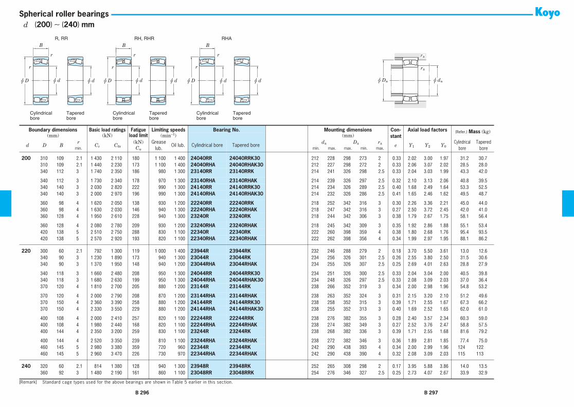
R, RR RH, RHR RHA
Cylindricalbore
Taperedbore
Cylindricalbore
Taperedbore
Cylindricalbore
Taperedbore
r
r
r
r
B B
r
r
B
u d u du D u d u du D u d u du D u Da u da
ra
ra
Spherical roller bearings
200 310 109 2.1 1 430 2 110 180 1 100 1 400 24040RR 24040RRK30 212 228 298 273 2 0.33 2.02 3.00 1.97 31.2 30.7200 310 109 2.1 1 440 2 230 173 1 100 1 400 24040RHA 24040RHAK30 212 227 298 272 2 0.33 2.06 3.07 2.02 28.5 28.0200 340 112 3 1 740 2 350 186 980 1 300 23140RR 23140RRK 214 241 326 298 2.5 0.33 2.04 3.03 1.99 43.3 42.0
200 340 112 3 1 730 2 340 178 970 1 300 23140RHA 23140RHAK 214 239 326 297 2.5 0.32 2.10 3.13 2.06 40.8 39.5200 340 140 3 2 030 2 820 222 990 1 300 24140RR 24140RRK30 214 234 326 289 2.5 0.40 1.68 2.49 1.64 53.3 52.5200 340 140 3 2 000 2 970 196 990 1 300 24140RHA 24140RHAK30 214 232 326 286 2.5 0.41 1.65 2.46 1.62 49.5 48.7
200 360 98 4 1 620 2 050 138 930 1 200 22240RR 22240RRK 218 252 342 316 3 0.30 2.26 3.36 2.21 45.0 44.0200 360 98 4 1 630 2 030 146 940 1 300 22240RHA 22240RHAK 218 247 342 316 3 0.27 2.50 3.72 2.45 42.0 41.0200 360 128 4 1 950 2 610 228 940 1 300 23240R 23240RK 218 244 342 306 3 0.38 1.79 2.67 1.75 58.1 56.4
200 360 128 4 2 080 2 780 209 930 1 200 23240RHA 23240RHAK 218 245 342 309 3 0.35 1.92 2.86 1.88 55.1 53.4200 420 138 5 2 510 2 750 288 830 1 100 22340R 22340RK 222 260 398 359 4 0.38 1.80 2.68 1.76 95.4 93.5200 420 138 5 2 570 2 920 193 820 1 100 22340RHA 22340RHAK 222 262 398 356 4 0.34 1.99 2.97 1.95 88.1 86.2
220 300 60 2.1 792 1 300 119 1 000 1 400 23944R 23944RK 232 246 288 279 2 0.18 3.70 5.50 3.61 13.0 12.6220 340 90 3 1 230 1 890 173 940 1 300 23044R 23044RK 234 256 326 301 2.5 0.26 2.55 3.80 2.50 31.5 30.6220 340 90 3 1 370 1 950 148 940 1 200 23044RHA 23044RHAK 234 255 326 307 2.5 0.25 2.69 4.01 2.63 28.8 27.9
220 340 118 3 1 660 2 480 208 950 1 300 24044RR 24044RRK30 234 251 326 300 2.5 0.33 2.04 3.04 2.00 40.5 39.8220 340 118 3 1 680 2 630 199 950 1 300 24044RHA 24044RHAK30 234 248 326 297 2.5 0.33 2.08 3.09 2.03 37.0 36.4220 370 120 4 1 810 2 700 205 880 1 200 23144R 23144RK 238 266 352 319 3 0.34 2.00 2.98 1.96 54.8 53.2
220 370 120 4 2 000 2 790 208 870 1 200 23144RHA 23144RHAK 238 263 352 324 3 0.31 2.15 3.20 2.10 51.2 49.6220 370 150 4 2 360 3 390 258 880 1 200 24144RR 24144RRK30 238 258 352 315 3 0.39 1.71 2.55 1.67 67.3 66.2220 370 150 4 2 330 3 550 229 880 1 200 24144RHA 24144RHAK30 238 255 352 313 3 0.40 1.69 2.52 1.65 62.0 61.0
220 400 108 4 2 000 2 410 257 820 1 100 22244RR 22244RRK 238 276 382 355 3 0.28 2.40 3.57 2.34 60.3 59.0220 400 108 4 1 980 2 440 168 820 1 100 22244RHA 22244RHAK 238 274 382 349 3 0.27 2.52 3.76 2.47 58.8 57.5220 400 144 4 2 350 3 200 259 830 1 100 23244R 23244RK 238 268 382 336 3 0.39 1.71 2.55 1.68 81.6 79.2
220 400 144 4 2 520 3 350 239 810 1 100 23244RHA 23244RHAK 238 272 382 346 3 0.36 1.89 2.81 1.85 77.4 75.0220 460 145 5 2 980 3 380 359 720 960 22344R 22344RK 242 290 438 393 4 0.34 2.00 2.99 1.96 124 122220 460 145 5 2 960 3 470 226 730 970 22344RHA 22344RHAK 242 290 438 390 4 0.32 2.08 3.09 2.03 115 113
240 320 60 2.1 814 1 380 128 940 1 300 23948R 23948RK 252 265 308 298 2 0.17 3.95 5.88 3.86 14.0 13.5240 360 92 3 1 480 2 190 161 860 1 100 23048RR 23048RRK 254 276 346 327 2.5 0.25 2.73 4.07 2.67 33.9 32.9
Boundary dimensions Basic load ratings Fatigue Limiting speeds Bearing No. Mounting dimensions Con-stant
Axial load factors (Refer.) Mass (kg)(mm) (kN) load limit (min−1) (mm)
d D Br
Cr C0r(kN) Grease
lub.Oil lub. Cylindrical bore Tapered bore
da Da ra e Y1 Y2 Y0Cylindrical
boreTapered
boremin. Cu min. max. max. min. max.
[Remark] Standard cage types used for the above bearings are shown in Table 5 earlier in this section.
B 296 B 297
d (200) ∼ (240) mm

R, RR RH, RHR RHA
Cylindricalbore
Taperedbore
Cylindricalbore
Taperedbore
Cylindricalbore
Taperedbore
r
r
r
r
B B
r
r
B
u d u du D u d u du D u d u du D u Da u da
ra
ra
Spherical roller bearings
240 360 92 3 1 470 2 180 166 860 1 100 23048RHA 23048RHAK 254 275 346 327 2.5 0.24 2.83 4.21 2.77 31.9 30.9240 360 118 3 1 750 2 710 228 870 1 200 24048RR 24048RRK30 254 272 346 321 2.5 0.31 2.20 3.27 2.15 43.5 42.9240 360 118 3 1 750 2 840 215 870 1 200 24048RHA 24048RHAK30 254 269 346 321 2.5 0.30 2.24 3.33 2.19 39.6 39.0
240 400 128 4 2 280 3 220 213 790 1 100 23148RR 23148RRK 258 287 382 353 3 0.32 2.11 3.14 2.06 67.2 65.1240 400 128 4 2 270 3 200 233 790 1 000 23148RHA 23148RHAK 258 286 382 353 3 0.31 2.19 3.25 2.14 63.1 61.1240 400 160 4 2 640 3 850 287 800 1 100 24148RR 24148RRK30 258 280 382 340 3 0.39 1.75 2.60 1.71 82.7 81.4
240 400 160 4 2 670 4 130 262 800 1 100 24148RHA 24148RHAK30 258 278 382 340 3 0.39 1.72 2.56 1.68 76.6 75.3240 440 120 4 2 390 2 940 295 730 970 22248R 22248RK 258 299 422 384 3 0.29 2.35 3.50 2.30 85.0 83.2240 440 120 4 2 400 2 990 202 730 970 22248RHA 22248RHAK 258 299 422 384 3 0.27 2.49 3.71 2.43 79.4 77.6
240 440 160 4 3 050 3 970 310 730 970 23248RR 23248RRK 258 295 422 376 3 0.38 1.78 2.64 1.74 110 107240 440 160 4 3 080 4 130 289 730 970 23248RHA 23248RHAK 258 295 422 376 3 0.36 1.87 2.78 1.83 104 101240 500 155 5 3 360 4 200 347 650 870 22348R 22348RK 262 320 478 420 4 0.35 1.94 2.89 1.90 157 154
240 500 155 5 3 400 3 990 255 650 870 22348RHA 22348RHAK 262 315 478 426 4 0.32 2.12 3.16 2.07 145 142
260 360 75 2.1 1 140 1 880 160 820 1 100 23952R 23952RK 272 292 348 333 2 0.19 3.54 5.27 3.46 24.0 23.3260 400 104 4 1 670 2 570 212 760 1 000 23052R 23052RK 278 304 382 359 3 0.25 2.65 3.95 2.59 50.7 49.3260 400 104 4 1 850 2 720 201 760 1 000 23052RHA 23052RHAK 278 302 382 359 3 0.25 2.75 4.10 2.69 46.3 44.9
260 400 140 4 2 280 3 570 282 770 1 000 24052RR 24052RRK30 278 296 382 352 3 0.33 2.02 3.01 1.98 66.3 65.2260 400 140 4 2 270 3 670 265 770 1 000 24052RHA 24052RHAK30 278 292 382 347 3 0.33 2.06 3.07 2.02 60.3 59.4260 440 144 4 2 760 3 850 231 710 940 23152RR 23152RRK 278 313 422 387 3 0.33 2.05 3.06 2.01 92.2 89.4
260 440 144 4 2 790 4 000 285 700 930 23152RHA 23152RHAK 278 311 422 384 3 0.32 2.12 3.16 2.08 87.4 84.6260 440 180 4 3 250 4 700 345 720 950 24152RR 24152RRK30 278 304 422 374 3 0.40 1.69 2.51 1.65 114 112260 440 180 4 3 210 4 950 309 720 950 24152RHA 24152RHAK30 278 299 422 368 3 0.41 1.66 2.47 1.62 106 105
260 480 130 5 2 800 3 460 347 650 870 22252R 22252RK 282 326 458 419 4 0.28 2.40 3.57 2.35 110 108260 480 130 5 2 790 3 430 226 650 870 22252RHA 22252RHAK 282 324 458 418 4 0.27 2.50 3.72 2.44 103 101260 480 174 5 3 440 4 640 326 640 860 23252R 23252RK 282 325 458 408 4 0.40 1.69 2.51 1.65 144 140
260 480 174 5 3 590 4 900 280 650 860 23252RHA 23252RHAK 282 322 458 408 4 0.36 1.87 2.78 1.83 137 133260 540 165 6 3 540 4 380 363 590 780 22352R 22352RK 288 346 512 453 5 0.35 1.94 2.89 1.90 196 192260 540 165 6 3 900 4 620 290 580 780 22352RHA 22352RHAK 288 342 512 461 5 0.31 2.15 3.21 2.11 181 177
280 380 75 2.1 1 160 1 960 165 760 1 000 23956R 23956RK 292 312 368 353 2 0.18 3.74 5.57 3.66 26.0 25.2
Boundary dimensions Basic load ratings Fatigue Limiting speeds Bearing No. Mounting dimensions Con-stant
Axial load factors (Refer.) Mass (kg)(mm) (kN) load limit (min−1) (mm)
d D Br
Cr C0r(kN) Grease
lub.Oil lub. Cylindrical bore Tapered bore
da Da ra e Y1 Y2 Y0Cylindrical
boreTapered
boremin. Cu min. max. max. min. max.
[Remark] Standard cage types used for the above bearings are shown in Table 5 earlier in this section.
B 298 B 299
d (240) ∼ (280) mm

R, RR RH, RHR RHA
Cylindricalbore
Taperedbore
Cylindricalbore
Taperedbore
Cylindricalbore
Taperedbore
r
r
r
r
B B
r
r
B
u d u du D u d u du D u d u du D u Da u da
ra
ra
Spherical roller bearings
280 420 106 4 1 790 2 860 235 710 950 23056R 23056RK 298 322 402 377 3 0.25 2.74 4.08 2.68 54.5 52.9280 420 106 4 1 940 2 950 218 700 940 23056RHA 23056RHAK 298 322 402 380 3 0.24 2.87 4.27 2.80 49.8 48.2280 420 140 4 2 370 3 780 291 710 950 24056RR 24056RRK30 298 316 402 373 3 0.31 2.15 3.21 2.11 70.2 69.1
280 420 140 4 2 390 4 000 287 710 950 24056RHA 24056RHAK30 298 314 402 372 3 0.31 2.20 3.28 2.15 64.0 62.9280 460 146 5 2 910 4 160 250 660 880 23156RR 23156RRK 302 332 438 407 4 0.32 2.14 3.18 2.09 98.8 95.7280 460 146 5 2 940 4 290 304 650 870 23156RHA 23156RHAK 302 331 438 406 4 0.30 2.22 3.30 2.17 93.4 90.3
280 460 180 5 3 390 5 140 370 660 880 24156RR 24156RRK30 302 326 438 396 4 0.38 1.79 2.67 1.75 122 120280 460 180 5 3 320 5 240 322 660 880 24156RHA 24156RHAK30 302 321 438 390 4 0.38 1.76 2.62 1.72 113 112280 500 130 5 2 640 3 380 308 610 810 22256R 22256RK 302 347 478 438 4 0.28 2.42 3.60 2.37 114 112
280 500 130 5 2 900 3 670 240 610 810 22256RHA 22256RHAK 302 346 478 440 4 0.26 2.64 3.93 2.58 106 104280 500 176 5 3 370 4 910 323 610 820 23256R 23256RK 302 345 478 421 4 0.37 1.83 2.72 1.79 153 149280 500 176 5 3 770 5 300 365 600 800 23256RHA 23256RHAK 302 343 478 430 4 0.35 1.95 2.91 1.91 145 141
280 580 175 6 3 930 4 910 407 530 710 22356R 22356RK 308 372 552 486 5 0.34 1.98 2.95 1.93 229 225280 580 175 6 4 390 5 260 325 530 700 22356RHA 22356RHAK 308 367 552 495 5 0.31 2.19 3.25 2.14 212 208
300 420 90 3 1 610 2 610 220 680 910 23960R 23960RK 314 336 406 387 2.5 0.20 3.42 5.09 3.34 40.0 38.8300 460 118 4 2 190 3 480 286 630 840 23060R 23060RK 318 351 442 412 3 0.25 2.69 4.00 2.63 75.8 73.7300 460 118 4 2 370 3 700 255 630 840 23060RHA 23060RHAK 318 347 442 416 3 0.24 2.79 4.16 2.73 68.9 66.8
300 460 160 4 2 950 4 690 354 640 850 24060RR 24060RRK30 318 342 442 406 3 0.33 2.04 3.04 2.00 99.5 97.9300 460 160 4 2 950 4 910 350 640 850 24060RHA 24060RHAK30 318 338 442 404 3 0.32 2.09 3.11 2.04 90.7 89.1300 500 160 5 3 450 5 030 351 590 790 23160RR 23160RRK 322 358 478 439 4 0.32 2.09 3.11 2.04 131 127
300 500 160 5 3 430 4 970 345 580 780 23160RHA 23160RHAK 322 357 478 439 4 0.31 2.18 3.25 2.13 123 119300 500 200 5 4 160 6 280 433 590 790 24160RR 24160RRK30 322 349 478 425 4 0.40 1.67 2.49 1.63 162 160300 500 200 5 4 030 6 420 385 590 790 24160RHA 24160RHAK30 322 347 478 424 4 0.39 1.72 2.56 1.68 150 148
300 540 140 5 3 360 4 330 412 550 740 22260R 22260RK 322 368 518 467 4 0.27 2.48 3.69 2.43 145 142300 540 140 5 3 320 4 360 284 550 740 22260RHA 22260RHAK 322 370 518 467 4 0.26 2.62 3.90 2.56 135 132300 540 192 5 4 300 5 910 401 540 720 23260R 23260RK 322 370 518 464 4 0.37 1.83 2.72 1.79 197 192
300 540 192 5 4 440 6 310 429 540 720 23260RHA 23260RHAK 322 371 518 464 4 0.35 1.93 2.88 1.89 187 182300 620 185 7.5 4 890 5 430 555 470 630 22360R 22360RK 336 390 584 547 6 0.32 2.09 3.10 2.04 289 284
320 440 90 3 1 670 2 870 233 630 840 23964R 23964RK 334 358 426 408 2.5 0.19 3.61 5.38 3.53 43.0 41.7
Boundary dimensions Basic load ratings Fatigue Limiting speeds Bearing No. Mounting dimensions Con-stant
Axial load factors (Refer.) Mass (kg)(mm) (kN) load limit (min−1) (mm)
d D Br
Cr C0r(kN) Grease
lub.Oil lub. Cylindrical bore Tapered bore
da Da ra e Y1 Y2 Y0Cylindrical
boreTapered
boremin. Cu min. max. max. min. max.
[Remark] Standard cage types used for the above bearings are shown in Table 5 earlier in this section.
B 300 B 301
d (280) ∼ (320) mm

R, RR RH, RHR RHA
Cylindricalbore
Taperedbore
Cylindricalbore
Taperedbore
Cylindricalbore
Taperedbore
r
r
r
r
B B
r
r
B
u d u du D u d u du D u d u du D u Da u da
ra
ra
Spherical roller bearings
320 480 121 4 2 290 3 740 295 590 790 23064R 23064RK 338 369 462 431 3 0.24 2.76 4.11 2.70 81.2 78.8320 480 121 4 2 490 3 850 278 590 780 23064RHA 23064RHAK 338 367 462 436 3 0.24 2.87 4.27 2.80 74.5 72.1320 480 160 4 3 020 4 920 382 590 790 24064RR 24064RRK30 338 363 462 427 3 0.31 2.16 3.22 2.11 105 103
320 480 160 4 3 060 5 230 363 590 790 24064RHA 24064RHAK30 338 360 462 425 3 0.31 2.21 3.29 2.16 93.4 91.4320 540 176 5 3 650 5 700 366 530 700 23164R 23164RK 342 389 518 467 4 0.33 2.04 3.04 2.00 171 166320 540 176 5 4 040 5 960 404 530 700 23164RHA 23164RHAK 342 383 518 472 4 0.32 2.13 3.17 2.08 160 155
320 540 218 5 4 680 6 950 486 530 710 24164RR 24164RRK30 342 373 518 460 4 0.39 1.72 2.56 1.68 208 205320 540 218 5 4 550 7 190 429 530 710 24164RHA 24164RHAK30 342 371 518 458 4 0.40 1.70 2.52 1.66 199 196320 580 150 5 3 420 4 540 385 490 660 22264R 22264RK 342 402 558 504 4 0.28 2.41 3.59 2.35 175 171
320 580 208 5 4 550 6 550 496 500 670 23264R 23264RK 342 394 558 488 4 0.38 1.76 2.62 1.72 249 242320 580 208 5 5 020 7 030 464 490 650 23264RHA 23264RHAK 342 392 558 495 4 0.36 1.90 2.83 1.86 236 229
340 460 90 3 1 680 2 980 242 590 790 23968R 23968RK 354 377 446 426 2.5 0.18 3.82 5.69 3.74 45.0 43.6340 520 133 5 2 670 4 330 353 530 710 23068R 23068RK 362 397 498 465 4 0.25 2.69 4.00 2.63 108 105340 520 133 5 2 930 4 470 312 530 710 23068RHA 23068RHAK 362 393 498 468 4 0.24 2.80 4.18 2.74 98.7 95.7
340 520 180 5 3 680 5 970 432 530 710 24068RR 24068RRK30 362 387 498 460 4 0.33 2.06 3.06 2.01 142 140340 520 180 5 3 720 6 330 430 530 710 24068RHA 24068RHAK30 362 385 498 459 4 0.32 2.11 3.14 2.06 130 128340 580 190 5 4 130 6 430 472 480 640 23168R 23168RK 362 413 558 497 4 0.34 1.97 2.93 1.93 216 210
340 580 190 5 4 620 6 720 449 480 640 23168RHA 23168RHAK 362 407 558 503 4 0.32 2.11 3.14 2.06 202 196340 580 243 5 5 570 8 400 564 490 650 24168RR 24168RRK30 362 396 558 490 4 0.41 1.64 2.45 1.61 270 266340 580 243 5 5 490 8 810 449 490 650 24168RHA 24168RHAK30 362 390 558 482 4 0.42 1.61 2.39 1.57 259 255
340 620 165 6 4 430 5 430 551 440 590 22268R 22268RK 368 424 592 551 5 0.28 2.43 3.61 2.37 221 216340 620 224 6 5 130 7 560 526 450 600 23268R 23268RK 368 423 592 521 5 0.38 1.77 2.63 1.73 306 297340 620 224 6 5 690 8 030 517 440 590 23268RHA 23268RHAK 368 418 592 532 5 0.36 1.88 2.81 1.84 290 281
360 480 90 3 1 710 3 060 248 550 730 23972R 23972RK 374 399 466 447 2.5 0.17 3.95 5.88 3.86 46.5 45.0360 540 134 5 2 860 4 800 375 500 660 23072R 23072RK 382 416 518 484 4 0.24 2.76 4.11 2.70 115 111360 540 134 5 3 040 4 770 334 500 660 23072RHA 23072RHAK 382 414 518 489 4 0.23 2.92 4.34 2.85 105 101
360 540 180 5 3 810 6 300 465 500 660 24072RR 24072RRK30 382 407 518 481 4 0.31 2.15 3.21 2.11 149 147360 540 180 5 3 810 6 620 446 500 660 24072RHA 24072RHAK30 382 406 518 480 4 0.30 2.22 3.30 2.17 135 133360 600 192 5 4 740 7 040 459 440 590 23172R 23172RK 382 431 578 527 4 0.33 2.07 3.09 2.03 228 221
Boundary dimensions Basic load ratings Fatigue Limiting speeds Bearing No. Mounting dimensions Con-stant
Axial load factors (Refer.) Mass (kg)(mm) (kN) load limit (min−1) (mm)
d D Br
Cr C0r(kN) Grease
lub.Oil lub. Cylindrical bore Tapered bore
da Da ra e Y1 Y2 Y0Cylindrical
boreTapered
boremin. Cu min. max. max. min. max.
[Remark] Standard cage types used for the above bearings are shown in Table 5 earlier in this section.
B 302 B 303
d (320) ∼ (360) mm

R, RR RH, RHR RHA
Cylindricalbore
Taperedbore
Cylindricalbore
Taperedbore
Cylindricalbore
Taperedbore
r
r
r
r
B B
r
r
B
u d u du D u d u du D u d u du D u Da u da
ra
ra
Spherical roller bearings
360 600 192 5 4 830 7 210 474 450 590 23172RHA 23172RHAK 382 429 578 527 4 0.31 2.19 3.25 2.14 213 206360 600 243 5 5 080 7 690 437 450 600 24172R 24172RK30 382 420 578 512 4 0.39 1.74 2.59 1.70 287 283360 600 243 5 5 580 9 180 517 460 610 24172RHA 24172RHAK30 382 413 578 505 4 0.40 1.69 2.51 1.65 274 270
360 650 170 6 4 710 5 830 583 410 550 22272R 22272RK 388 447 622 579 5 0.27 2.47 3.68 2.42 248 243360 650 232 6 6 080 8 810 548 410 540 23272R 23272RK 388 446 622 555 5 0.37 1.83 2.72 1.79 346 336360 650 232 6 6 220 9 050 591 410 550 23272RHA 23272RHAK 388 442 622 558 5 0.35 1.92 2.85 1.87 328 318
380 520 106 4 2 220 3 940 295 500 660 23976R 23976RK 398 425 502 481 3 0.19 3.62 5.39 3.54 70.0 67.9380 560 135 5 2 910 4 970 355 470 630 23076R 23076RK 402 433 538 503 4 0.24 2.79 4.16 2.73 122 118380 560 135 5 3 160 5 080 354 460 620 23076RHA 23076RHAK 402 434 538 512 4 0.22 3.03 4.51 2.96 112 108
380 560 180 5 3 900 6 590 486 470 620 24076RR 24076RRK30 402 428 538 502 4 0.30 2.26 3.36 2.21 156 154380 560 180 5 3 900 6 910 454 470 620 24076RHA 24076RHAK30 402 426 538 502 4 0.29 2.32 3.45 2.27 142 139380 620 194 5 4 520 7 320 442 420 560 23176R 23176RK 402 454 598 540 4 0.31 2.18 3.24 2.13 240 233
380 620 194 5 5 030 7 700 503 420 560 23176RHA 23176RHAK 402 450 598 547 4 0.30 2.26 3.36 2.21 224 217380 620 243 5 5 300 8 220 467 430 570 24176R 24176RK30 402 439 598 529 4 0.38 1.78 2.65 1.74 302 297380 620 243 5 5 870 9 840 561 420 560 24176RHA 24176RHAK30 402 438 598 534 4 0.38 1.78 2.65 1.74 288 283
380 680 240 6 6 510 9 500 590 380 500 23276R 23276RK 408 469 652 583 5 0.36 1.85 2.76 1.81 386 375380 680 240 6 6 660 9 760 622 380 510 23276RHA 23276RHAK 408 466 652 586 5 0.35 1.94 2.89 1.90 365 354
400 540 106 4 2 350 4 300 320 470 620 23980R 23980RK 418 443 522 500 3 0.18 3.76 5.59 3.67 73.0 70.7400 600 148 5 3 390 5 790 408 420 560 23080R 23080RK 422 462 578 540 4 0.24 2.84 4.23 2.78 155 151400 600 148 5 3 690 5 860 398 420 560 23080RHA 23080RHAK 422 460 578 543 4 0.23 2.94 4.37 2.87 142 138
400 600 200 5 4 820 8 110 444 430 570 24080R 24080RK30 422 450 578 531 4 0.32 2.09 3.12 2.05 206 203400 600 200 5 4 620 8 140 535 420 570 24080RHA 24080RHAK30 422 450 578 534 4 0.31 2.21 3.29 2.16 192 189400 650 200 6 4 730 7 780 521 390 520 23180R 23180RK 428 476 622 564 5 0.31 2.19 3.25 2.14 273 265
400 650 200 6 5 410 8 300 542 390 520 23180RHA 23180RHAK 428 473 622 574 5 0.29 2.30 3.43 2.25 255 247400 650 250 6 5 840 9 140 499 390 530 24180R 24180RK30 428 461 622 558 5 0.37 1.82 2.70 1.78 338 333400 650 250 6 6 290 10 600 600 390 520 24180RHA 24180RHAK30 428 462 622 558 5 0.37 1.82 2.71 1.78 322 317
400 720 256 6 6 540 9 850 590 350 470 23280R 23280RK 428 496 692 605 5 0.37 1.80 2.69 1.76 468 454400 720 256 6 7 320 10 600 665 350 460 23280RHA 23280RHAK 428 489 692 619 5 0.35 1.92 2.86 1.88 441 427
Boundary dimensions Basic load ratings Fatigue Limiting speeds Bearing No. Mounting dimensions Con-stant
Axial load factors (Refer.) Mass (kg)(mm) (kN) load limit (min−1) (mm)
d D Br
Cr C0r(kN) Grease
lub.Oil lub. Cylindrical bore Tapered bore
da Da ra e Y1 Y2 Y0Cylindrical
boreTapered
boremin. Cu min. max. max. min. max.
[Remark] Standard cage types used for the above bearings are shown in Table 5 earlier in this section.
B 304 B 305
d (360) ∼ 400 mm
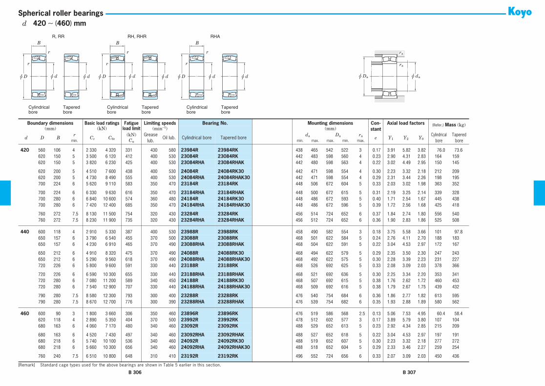
R, RR RH, RHR RHA
Cylindricalbore
Taperedbore
Cylindricalbore
Taperedbore
Cylindricalbore
Taperedbore
r
r
r
r
B B
r
r
B
u d u du D u d u du D u d u du D u Da u da
ra
ra
Spherical roller bearings
420 560 106 4 2 330 4 320 331 430 580 23984R 23984RK 438 465 542 522 3 0.17 3.91 5.82 3.82 76.0 73.6420 620 150 5 3 500 6 120 412 400 530 23084R 23084RK 442 483 598 560 4 0.23 2.90 4.31 2.83 164 159420 620 150 5 3 820 6 230 425 400 530 23084RHA 23084RHAK 442 480 598 563 4 0.22 3.02 4.49 2.95 150 145
420 620 200 5 4 510 7 600 438 400 530 24084R 24084RK30 442 471 598 554 4 0.30 2.23 3.32 2.18 212 209420 620 200 5 4 730 8 490 555 400 530 24084RHA 24084RHAK30 442 471 598 554 4 0.29 2.31 3.44 2.26 198 195420 700 224 6 5 620 9 110 583 350 470 23184R 23184RK 448 506 672 604 5 0.33 2.03 3.02 1.98 363 352
420 700 224 6 6 330 9 630 616 350 470 23184RHA 23184RHAK 448 500 672 615 5 0.31 2.19 3.25 2.14 339 328420 700 280 6 6 840 10 600 574 360 480 24184R 24184RK30 448 486 672 593 5 0.40 1.71 2.54 1.67 445 438420 700 280 6 7 420 12 400 685 350 470 24184RHA 24184RHAK30 448 486 672 596 5 0.39 1.72 2.56 1.68 425 418
420 760 272 7.5 8 130 11 500 754 320 430 23284R 23284RK 456 514 724 652 6 0.37 1.84 2.74 1.80 556 540420 760 272 7.5 8 230 11 900 735 320 430 23284RHA 23284RHAK 456 512 724 652 6 0.36 1.90 2.83 1.86 525 508
440 600 118 4 2 910 5 330 387 400 530 23988R 23988RK 458 490 582 554 3 0.18 3.75 5.58 3.66 101 97.8440 650 157 6 3 790 6 540 455 370 500 23088R 23088RK 468 501 622 584 5 0.24 2.76 4.11 2.70 188 183440 650 157 6 4 230 6 910 465 370 490 23088RHA 23088RHAK 468 504 622 591 5 0.22 3.04 4.53 2.97 172 167
440 650 212 6 4 910 8 320 475 370 490 24088R 24088RK30 468 494 622 579 5 0.29 2.35 3.50 2.30 247 243440 650 212 6 5 290 9 560 618 370 490 24088RHA 24088RHAK30 468 492 622 575 5 0.30 2.28 3.39 2.23 231 227440 720 226 6 5 800 9 600 591 330 440 23188R 23188RK 468 526 692 625 5 0.33 2.08 3.09 2.03 378 366
440 720 226 6 6 590 10 300 655 330 440 23188RHA 23188RHAK 468 521 692 636 5 0.30 2.25 3.34 2.20 353 341440 720 280 6 7 080 11 200 589 340 450 24188R 24188RK30 468 507 692 615 5 0.38 1.76 2.62 1.72 460 453440 720 280 6 7 540 12 900 707 330 440 24188RHA 24188RHAK30 468 509 692 616 5 0.38 1.79 2.67 1.75 439 432
440 790 280 7.5 8 580 12 300 793 300 400 23288R 23288RK 476 540 754 684 6 0.36 1.86 2.77 1.82 613 595440 790 280 7.5 8 670 12 700 776 300 390 23288RHA 23288RHAK 476 539 754 682 6 0.35 1.93 2.88 1.89 580 562
460 600 90 3 1 800 3 660 306 350 460 23896R 23896RK 476 519 586 568 2.5 0.13 5.06 7.53 4.95 60.4 58.4460 620 118 4 2 890 5 350 404 370 500 23992R 23992RK 478 512 602 577 3 0.17 3.89 5.79 3.80 107 104460 680 163 6 4 060 7 170 480 340 460 23092R 23092RK 488 529 652 613 5 0.23 2.92 4.34 2.85 215 209
460 680 163 6 4 520 7 430 497 340 460 23092RHA 23092RHAK 488 527 652 618 5 0.22 3.04 4.53 2.97 197 191460 680 218 6 5 740 10 100 536 340 460 24092R 24092RK30 488 519 652 607 5 0.30 2.23 3.32 2.18 277 272460 680 218 6 5 660 10 300 656 340 460 24092RHA 24092RHAK30 488 518 652 604 5 0.29 2.33 3.46 2.27 259 254
460 760 240 7.5 6 510 10 800 648 310 410 23192R 23192RK 496 552 724 656 6 0.33 2.07 3.09 2.03 450 436
Boundary dimensions Basic load ratings Fatigue Limiting speeds Bearing No. Mounting dimensions Con-stant
Axial load factors (Refer.) Mass (kg)(mm) (kN) load limit (min−1) (mm)
d D Br
Cr C0r(kN) Grease
lub.Oil lub. Cylindrical bore Tapered bore
da Da ra e Y1 Y2 Y0Cylindrical
boreTapered
boremin. Cu min. max. max. min. max.
[Remark] Standard cage types used for the above bearings are shown in Table 5 earlier in this section.
B 306 B 307
d 420 ∼ (460) mm

R, RR RH, RHR RHA
Cylindricalbore
Taperedbore
Cylindricalbore
Taperedbore
Cylindricalbore
Taperedbore
r
r
r
r
B B
r
r
B
u d u du D u d u du D u d u du D u Da u da
ra
ra
Spherical roller bearings
460 760 240 7.5 7 240 11 200 697 300 400 23192RHA 23192RHAK 496 546 724 669 6 0.30 2.22 3.31 2.17 420 406460 760 300 7.5 7 320 12 200 597 310 410 24192R 24192RK30 496 537 724 647 6 0.35 1.95 2.90 1.91 550 541460 760 300 7.5 8 390 14 200 746 310 410 24192RHA 24192RHAK30 496 535 724 651 6 0.38 1.75 2.61 1.72 525 516
460 830 296 7.5 9 520 13 700 867 270 370 23292R 23292RK 496 567 794 718 6 0.36 1.85 2.76 1.81 720 699460 830 296 7.5 9 600 14 200 856 270 360 23292RHA 23292RHAK 496 564 794 714 6 0.35 1.92 2.85 1.87 679 658
480 650 128 5 3 290 6 130 446 350 460 23996R 23996RK 502 534 628 603 4 0.18 3.75 5.59 3.67 123 119480 700 165 6 4 190 7 540 505 320 430 23096R 23096RK 508 549 672 633 5 0.22 3.01 4.47 2.94 225 218480 700 165 6 4 670 7 860 532 320 430 23096RHA 23096RHAK 508 548 672 639 5 0.22 3.12 4.64 3.05 206 199
480 700 218 6 5 540 9 650 514 320 430 24096R 24096RK30 508 539 672 626 5 0.29 2.32 3.45 2.26 287 282480 700 218 6 5 800 10 700 492 320 430 24096RHA 24096RHAK30 508 537 672 626 5 0.28 2.41 3.59 2.35 268 263480 790 248 7.5 6 840 11 500 698 280 380 23196R 23196RK 516 579 754 685 6 0.32 2.09 3.12 2.05 503 488
480 790 248 7.5 7 740 12 000 638 280 380 23196RHA 23196RHAK 516 570 754 697 6 0.30 2.24 3.34 2.19 470 455480 790 308 7.5 8 730 14 800 707 280 380 24196R 24196RK30 516 560 754 678 6 0.39 1.74 2.59 1.70 606 597480 790 308 7.5 9 880 15 900 792 290 380 24196RHA 24196RHAK30 516 553 754 684 6 0.38 1.78 2.65 1.74 580 568
480 870 310 7.5 10 500 15 100 953 250 340 23296R 23296RK 516 588 834 745 6 0.36 1.85 2.75 1.81 831 807480 870 310 7.5 10 600 15 700 791 250 340 23296RHA 23296RHAK 516 589 834 748 6 0.35 1.91 2.85 1.87 785 761
500 670 128 5 3 330 6 310 447 330 440 239/500R 239/500RK 522 553 648 622 4 0.17 3.87 5.76 3.79 131 127500 720 167 6 4 490 8 090 561 310 410 230/500R 230/500RK 528 568 692 656 5 0.23 2.94 4.37 2.87 235 228500 720 218 6 5 620 10 300 545 310 410 240/500R 240/500RK30 528 561 692 647 5 0.28 2.39 3.56 2.34 297 292
500 830 264 7.5 7 750 13 000 708 260 350 231/500R 231/500RK 536 601 794 714 6 0.33 2.05 3.05 2.00 595 577500 830 325 7.5 9 350 15 900 763 260 350 241/500R 241/500RK30 536 591 794 712 6 0.36 1.85 2.76 1.81 712 701500 920 336 7.5 11 000 16 700 908 230 310 232/500R 232/500RK 536 622 884 774 6 0.39 1.74 2.59 1.70 1 020 992
Boundary dimensions Basic load ratings Fatigue Limiting speeds Bearing No. Mounting dimensions Con-stant
Axial load factors (Refer.) Mass (kg)(mm) (kN) load limit (min−1) (mm)
d D Br
Cr C0r(kN) Grease
lub.Oil lub. Cylindrical bore Tapered bore
da Da ra e Y1 Y2 Y0Cylindrical
boreTapered
boremin. Cu min. max. max. min. max.
[Remark] Standard cage types used for the above bearings are shown in Table 5 earlier in this section.
B 308 B 309
d (460) ∼ 500 mm

d1 ≤ 180 mm d1 ≥ 200 mm
B2
B3
B1 B1
u d1 u d2 u d1 u d2
B2
b
A
u de u K
Adapter assemblies for spherical roller bearings
Boundary dimensions Brg.bore
d
(mm)
Designations
Mounting dimensions
Mass
(Refer.)
(mm)
Bearing
+
adapter ass'y
(mm)
Brg.
+
adapter ass'y
d
1
B
1
d
2
B
2
B
3
A K d
e
b
Adaptersleeve No.
LocknutNo.min. min. min. min.
(kg)
20
29 38 8
⎯
25 22205RHRK
+
H305X
15 45 29 5 0.269 A305X AN05
25
31 45 8
⎯
30 22206RHRK
+
H306X
15 50 34 5 0.404 A306X AN06
25
31 45 8
⎯
30 21306RHK
+
H306X
15 50 34 6 0.538 A306X AN06
30
35 52 9
⎯
35 22207RHRK
+
H307X
17 58 39 5 0.610 A307X AN07
30
35 52 9
⎯
35 21307RHK
+
H307X
17 58 39 7 0.725 A307X AN07
35
36 58 10
⎯
40 22208RHRK
+
H308X
17 65 44 5 0.793 A308X AN08
35
36 58 10
⎯
40 21308RHK
+
H308X
17 65 44 5 0.972 A308X AN08
35
46 58 10
⎯
40 22308RHRK
+
H2308X
17 65 45 5 1.30 A2308X AN08
40
39 65 11
⎯
45 22209RHRK
+
H309X
17 72 49 8 0.855 A309X AN09
40
39 65 11
⎯
45 21309RHK
+
H309X
17 72 49 5 1.31 A309X AN09
40
50 65 11
⎯
45 22309RHRK
+
H2309X
17 72 50 5 1.70 A2309X AN09
45
42 70 12
⎯
50 22210RHRK
+
H310X
19 76 54 10 0.953 A310X AN10
45
42 70 12
⎯
50 21310RHK
+
H310X
19 76 54 5 1.67 A310X AN10
45
55 70 12
⎯
50 22310RHRK
+
H2310X
19 76 56 5 2.26 A2310X AN10
50
45 75 12
⎯
55 22211RHRK
+
H311X
19 85 60 11 1.22 A311X AN11
50
45 75 12
⎯
55 21311RHK
+
H311X
19 85 60 6 2.04 A311X AN11
50
59 75 12
⎯
55 22311RHRK
+
H2311X
19 85 61 6 2.80 A2311X AN11
55
47 80 13
⎯
60 22212RHRK
+
H312X
20 90 65 9 1.59 A312X AN12
55
47 80 13
⎯
60 21312RHK
+
H312X
20 90 65 5 2.50 A312X AN12
55
62 80 13
⎯
60 22312RHRK
+
H2312X
20 90 66 5 3.50 A2312X AN12
60
50 85 14
⎯
65 22213RHRK
+
H313X
21 96 70 8 2.01 A313X AN13
60
50 85 14
⎯
65 21313RHK
+
H313X
21 96 70 5 3.07 A313X AN13
60
65 85 14
⎯
65 22313RHRK
+
H2313X
21 96 72 5 4.17 A2313X AN13
65
55 98 15
⎯
75 22215RHRK
+
H315X
23 110 80 12 2.58 A315X AN15
65
55 98 15
⎯
75 21315RHK
+
H315X
23 110 80 5 4.65 A315X AN15
65
73 98 15
⎯
75 22315RHRK
+
H2315X
23 110 82 5 6.44 A2315X AN15
70
59 105 17
⎯
80 22216RHRK
+
H316X
25 120 86 12 3.22 A316X AN16
70
59 105 17
⎯
80 21316RHK
+
H316X
25 120 86 5 5.56 A316X AN16
70
78 105 17
⎯
80 22316RHRK
+
H2316X
25 120 87 5 7.64 A2316X AN16
75
63 110 18
⎯
85 22217RHRK
+
H317X
27 128 91 12 3.93 A317X AN17
75
63 110 18
⎯
85 21317RHK
+
H317X
27 128 91 6 6.49 A317X AN17
75
82 110 18
⎯
85 22317RHRK
+
H2317X
27 128 94 6 8.83 A2317X AN17
80
65 120 18
⎯
90 22218RHRK
+
H318X
28 139 96 10 4.88 A318X AN18
80
86 120 18
⎯
90 23218RHK
+
H2318X
28 139 99 18 6.20 A2318X AN18
80
65 120 18
⎯
90 21318RHK
+
H318X
28 139 96 6 7.56 A318X AN18
80
86 120 18
⎯
90 22318RHRK
+
H2318X
28 139 99 6 10.3 A2318X AN18
85
68 125 19
⎯
95 22219RHRK
+
H319X
29 145 102 9 5.77 A319X AN19
85
68 125 19
⎯
95 21319RHK
+
H319X
29 145 102 7 8.68 A319X AN19
85
90 125 19
⎯
95 22319RHRK
+
H2319X
29 145 105 7 12.0 A2319X AN19
90
71 130 20
⎯
100 22220RHRK
+
H320X
30 150 107 8 6.80 A320X AN20
90
97 130 20
⎯
100 23220RHK
+
H2320X
30 150 110 19 8.94 A2320X AN20
90
71 130 20
⎯
100 21320RHK
+
H320X
30 150 107 7 10.5 A320X AN20
90
97 130 20
⎯
100 22320RHRK
+
H2320X
30 150 110 7 15.2 A2320X AN20
100
81 145 21
⎯
110 23122RHK
+
H3122X
32 170 117 7 7.91 A3122X AN22
100
77 145 21
⎯
110 22222RHRK
+
H322X
32 170 117 6 9.50 A322X AN22
100
105 145 21
⎯
110 23222RHK
+
H2322X
32 170 121 17 12.4 A2322X AN22
100
77 145 21
⎯
110 21322RHK
+
H322X
32 170 117 9 14.0 A322X AN22
100
105 145 21
⎯
110 22322RHRK
+
H2322X
32 170 121 7 20.6 A2322X AN22
110
72 145 22
⎯
120 23024RHK
+
H3024X
33 180 127 7 6.12 A3024 ANL24
110
88 155 22
⎯
120 23124RHK
+
H3124X
33 180 128 7 10.5 A3124 AN24
110
88 155 22
⎯
120 22224RHRK
+
H3124X
33 180 128 11 11.9 A3124 AN24
110
112 155 22
⎯
120 23224RHK
+
H2324X
33 180 131 17 15.1 A2324 AN24
110
112 155 22
⎯
120 22324RHRK
+
H2324X
33 180 131 7 25.6 A2324 AN24
Boundary dimensions Brg.bore
d
(mm)
Designations
Mounting dimensions
Mass
(Refer.)
(mm)
Bearing
+
adapter ass'y
(mm)
Brg.
+
adapter ass'y
d
1
B
1
d
2
B
2
B
3
A K d
e
b
Adaptersleeve No.
LocknutNo.min. min. min. min.
(kg)
B 310 B 311
d
1 20 ∼ 65 mm d1 70 ∼ 110 mm

d1 ≤ 180 mm d1 ≥ 200 mm
B2
B3
B1 B1
u d1 u d2 u d1 u d2
B2
b
A
u de u K
Adapter assemblies for spherical roller bearings
115 80 155 23 ⎯ 130 23026RHK+H3026 34 190 137 8 9.01 A3026 ANL26115 92 165 23 ⎯ 130 23126RHK+H3126 34 190 138 8 12.3 A3126 AN26115 92 165 23 ⎯ 130 22226RHRK+H3126 34 190 138 8 15.1 A3126 AN26
115 121 165 23 ⎯ 130 23226RHK+H2326 34 190 142 21 18.8 A2326 AN26115 121 165 23 ⎯ 130 22326RHRK+H2326 34 190 142 8 32.7 A2326 AN26
125 82 165 24 ⎯ 140 23028RHK+H3028 36 205 147 8 9.79 A3028 ANL28125 97 180 24 ⎯ 140 23128RHK+H3128 36 205 149 8 14.9 A3128 AN28125 97 180 24 ⎯ 140 22228RHRK+H3128 36 205 149 8 18.8 A3128 AN28
125 131 180 24 ⎯ 140 23228RHK+H2328 36 205 152 22 24.3 A2328 AN28125 131 180 24 ⎯ 140 22328RHK+H2328 36 205 152 8 40.8 A2328 AN28
135 87 180 26 ⎯ 150 23030RHK+H3030 37 220 158 8 11.9 A3030 ANL30135 111 195 26 ⎯ 150 23130RHK+H3130 37 220 160 8 21.7 A3130 AN30135 111 195 26 ⎯ 150 22230RHRK+H3130 37 220 160 15 24.3 A3130 AN30
135 139 195 26 ⎯ 150 23230RHK+H2330 37 220 163 20 30.8 A2330 AN30135 139 195 26 ⎯ 150 22330RK+H2330 37 220 163 8 49.7 A2330 AN30135 139 195 26 ⎯ 150 22330RHAK+H2330 37 220 163 8 46.4 A2330 AN30
140 93 190 28 ⎯ 160 23032RHK+H3032 39 230 168 8 15.0 A3032 ANL32140 119 210 28 ⎯ 160 23132RHK+H3132 39 230 170 8 27.9 A3132 AN32140 119 210 28 ⎯ 160 22232RK+H3132 39 230 170 14 30.6 A3132 AN32
140 119 210 28 ⎯ 160 22232RHAK+H3132 39 230 170 14 29.1 A3132 AN32140 147 210 28 ⎯ 160 23232RK+H2332 39 230 174 18 39.6 A2332 AN32140 147 210 28 ⎯ 160 23232RHAK+H2332 39 230 174 18 38.0 A2332 AN32
140 147 210 28 ⎯ 160 22332RK+H2332 39 230 174 8 60.5 A2332 AN32140 147 210 28 ⎯ 160 22332RHAK+H2332 39 230 174 8 56.6 A2332 AN32
150 101 200 29 ⎯ 170 23034RHK+H3034 40 250 179 8 19.2 A3034 ANL34150 122 220 29 ⎯ 170 23134RHK+H3134 40 250 180 8 30.0 A3134 AN34150 122 220 29 ⎯ 170 22234RK+H3134 40 250 180 10 37.2 A3134 AN34
150 122 220 29 ⎯ 170 22234RHAK+H3134 40 250 180 10 35.3 A3134 AN34
Boundary dimensions Brg.bore
d(mm)
Designations Mounting dimensions Mass(Refer.)(mm)
Bearing + adapter ass'y
(mm) Brg.+adapter ass'y
d1 B1 d2 B2 B3A K de b Adapter
sleeve No.Locknut
No.min. min. min. min. (kg)
150 154 220 29 ⎯ 170 23234RRK+H2334 40 250 185 18 47.2 A2334 AN34150 154 220 29 ⎯ 170 23234RHAK+H2334 40 250 185 18 45.3 A2334 AN34150 154 220 29 ⎯ 170 22334RK+H2334 40 250 185 8 71.5 A2334 AN34
150 154 220 29 ⎯ 170 22334RHAK+H2334 40 250 185 8 66.8 A2334 AN34
160 109 210 30 ⎯ 180 23036RHK+H3036 41 260 189 8 24.2 A3036 ANL36160 131 230 30 ⎯ 180 23136RK+H3136 41 260 191 8 37.1 A3136 AN36160 131 230 30 ⎯ 180 23136RHAK+H3136 41 260 191 8 35.2 A3136 AN36
160 131 230 30 ⎯ 180 22236RK+H3136 41 260 191 18 39.4 A3136 AN36160 131 230 30 ⎯ 180 22236RHAK+H3136 41 260 191 18 37.4 A3136 AN36160 161 230 30 ⎯ 180 23236RRK+H2336 41 260 195 22 50.5 A2336 AN36
160 161 230 30 ⎯ 180 23236RHAK+H2336 41 260 195 22 48.4 A2336 AN36160 161 230 30 ⎯ 180 22336RK+H2336 41 260 195 8 81.8 A2336 AN36160 161 230 30 ⎯ 180 22336RHAK+H2336 41 260 195 8 76.4 A2336 AN36
170 112 220 31 ⎯ 190 23038RK+H3038 43 270 199 9 26.1 A3038 ANL38170 112 220 31 ⎯ 190 23038RHAK+H3038 43 270 199 9 24.5 A3038 ANL38170 141 240 31 ⎯ 190 23138RK+H3138 43 270 202 9 45.3 A3138 AN38
170 141 240 31 ⎯ 190 23138RHAK+H3138 43 270 202 9 43.0 A3138 AN38170 141 240 31 ⎯ 190 22238RK+H3138 43 270 202 21 47.5 A3138 AN38170 141 240 31 ⎯ 190 22238RHAK+H3138 43 270 202 21 45.0 A3138 AN38
170 169 240 31 ⎯ 190 23238RRK+H2338 43 270 206 21 59.2 A2338 AN38170 169 240 31 ⎯ 190 23238RHAK+H2338 43 270 206 21 56.7 A2338 AN38170 169 240 31 ⎯ 190 22338RK+H2338 43 270 206 9 95.6 A2338 AN38
170 169 240 31 ⎯ 190 22338RHAK+H2338 43 270 206 9 89.2 A2338 AN38
180 120 240 32 ⎯ 200 23040RK+H3040 46 280 210 10 32.8 A3040 ANL40180 120 240 32 ⎯ 200 23040RHAK+H3040 46 280 210 10 30.7 A3040 ANL40180 150 250 32 ⎯ 200 23140RRK+H3140 46 280 212 10 54.7 A3140 AN40
180 150 250 32 ⎯ 200 23140RHAK+H3140 46 280 212 10 51.8 A3140 AN40180 150 250 32 ⎯ 200 22240RRK+H3140 46 280 212 24 56.3 A3140 AN40
Boundary dimensions Brg.bore
d(mm)
Designations Mounting dimensions Mass(Refer.)(mm)
Bearing + adapter ass'y
(mm) Brg.+adapter ass'y
d1 B1 d2 B2 B3A K de b Adapter
sleeve No.Locknut
No.min. min. min. min. (kg)
B 312 B 313
d1 115 ∼ (150) mm d1 (150) ∼ (180) mm

d1 ≤ 180 mm d1 ≥ 200 mm
B2
B3
B1 B1
u d1 u d2 u d1 u d2
B2
b
A
u de u K
Adapter assemblies for spherical roller bearings
180 150 250 32 ⎯ 200 22240RHAK+H3140 46 280 212 24 53.3 A3140 AN40180 176 250 32 ⎯ 200 23240RK+H2340 46 280 216 20 71.0 A2340 AN40180 176 250 32 ⎯ 200 23240RHAK+H2340 46 280 216 20 68.0 A2340 AN40
180 176 250 32 ⎯ 200 22340RK+H2340 46 280 216 10 108 A2340 AN40180 176 250 32 ⎯ 200 22340RHAK+H2340 46 280 216 10 101 A2340 AN40
200 128 260 30 41 220 23044RK+H3044 ⎯ ⎯ 231 12 41.4 A3044 ANL44200 128 260 30 41 220 23044RHAK+H3044 ⎯ ⎯ 231 12 38.7 A3044 ANL44200 158 280 32 44 220 23144RK+H3144 ⎯ ⎯ 233 10 68.4 A3144 AN44
200 158 280 32 44 220 23144RHAK+H3144 ⎯ ⎯ 233 10 64.8 A3144 AN44200 158 280 32 44 220 22244RRK+H3144 ⎯ ⎯ 233 22 76.9 A3144 AN44200 158 280 32 44 220 22244RHAK+H3144 ⎯ ⎯ 233 22 72.7 A3144 AN44
200 183 280 32 44 220 23244RK+H2344 ⎯ ⎯ 236 11 96.5 A2344 AN44200 183 280 32 44 220 23244RHAK+H2344 ⎯ ⎯ 236 11 92.3 A2344 AN44200 183 280 32 44 220 22344RK+H2344 ⎯ ⎯ 236 10 139 A2344 AN44
200 183 280 32 44 220 22344RHAK+H2344 ⎯ ⎯ 236 10 130 A2344 AN44
220 133 290 34 46 240 23048RRK+H3048 ⎯ ⎯ 251 11 47.7 A3048 ANL48220 133 290 34 46 240 23048RHAK+H3048 ⎯ ⎯ 251 11 44.8 A3048 ANL48220 169 300 34 46 240 23148RRK+H3148 ⎯ ⎯ 254 11 83.6 A3148 AN48
220 169 300 34 46 240 23148RHAK+H3148 ⎯ ⎯ 254 11 79.1 A3148 AN48220 169 300 34 46 240 22248RK+H3148 ⎯ ⎯ 254 19 101 A3148 AN48220 169 300 34 46 240 22248RHAK+H3148 ⎯ ⎯ 254 19 95.6 A3148 AN48
220 196 300 34 46 240 23248RRK+H2348 ⎯ ⎯ 257 6 128 A2348 AN48220 196 300 34 46 240 23248RHAK+H2348 ⎯ ⎯ 257 6 122 A2348 AN48220 196 300 34 46 240 22348RK+H2348 ⎯ ⎯ 257 11 175 A2348 AN48
220 196 300 34 46 240 22348RHAK+H2348 ⎯ ⎯ 257 11 163 A2348 AN48
240 147 310 34 46 260 23052RK+H3052 ⎯ ⎯ 272 13 65.4 A3052 ANL52240 147 310 34 46 260 23052RHAK+H3052 ⎯ ⎯ 272 13 61.0 A3052 ANL52240 187 330 36 49 260 23152RRK+H3152 ⎯ ⎯ 276 11 114 A3152 AN52
Boundary dimensions Brg.bore
d(mm)
Designations Mounting dimensions Mass(Refer.)(mm)
Bearing + adapter ass'y
(mm) Brg.+adapter ass'y
d1 B1 d2 B2 B3A K de b Adapter
sleeve No.Locknut
No.min. min. min. min. (kg)
240 187 330 36 49 260 23152RHAK+H3152 ⎯ ⎯ 276 11 108 A3152 AN52240 187 330 36 49 260 22252RK+H3152 ⎯ ⎯ 276 25 131 A3152 AN52240 187 330 36 49 260 22252RHAK+H3152 ⎯ ⎯ 276 25 124 A3152 AN52
240 208 330 36 49 260 23252RK+H2352 ⎯ ⎯ 278 2 165 A2352 AN52240 208 330 36 49 260 23252RHAK+H2352 ⎯ ⎯ 278 2 158 A2352 AN52240 208 330 36 49 260 22352RK+H2352 ⎯ ⎯ 278 11 217 A2352 AN52
240 208 330 36 49 260 22352RHAK+H2352 ⎯ ⎯ 278 11 202 A2352 AN52
260 152 330 38 50 280 23056RK+H3056 ⎯ ⎯ 292 12 71.5 A3056 ANL56260 152 330 38 50 280 23056RHAK+H3056 ⎯ ⎯ 292 12 66.8 A3056 ANL56260 192 350 38 51 280 23156RRK+H3156 ⎯ ⎯ 296 12 123 A3156 AN56
260 192 350 38 51 280 23156RHAK+H3156 ⎯ ⎯ 296 12 116 A3156 AN56260 192 350 38 51 280 22256RK+H3156 ⎯ ⎯ 296 28 138 A3156 AN56260 192 350 38 51 280 22256RHAK+H3156 ⎯ ⎯ 296 28 130 A3156 AN56
260 221 350 38 51 280 23256RK+H2356 ⎯ ⎯ 299 11 178 A2356 AN56260 221 350 38 51 280 23256RHAK+H2356 ⎯ ⎯ 299 11 170 A2356 AN56260 221 350 38 51 280 22356RK+H2356 ⎯ ⎯ 299 12 254 A2356 AN56
260 221 350 38 51 280 22356RHAK+H2356 ⎯ ⎯ 299 12 237 A2356 AN56
280 168 360 42 54 300 23060RK+H3060 ⎯ ⎯ 313 12 97.7 A3060 ANL60280 168 360 42 54 300 23060RHAK+H3060 ⎯ ⎯ 313 12 90.8 A3060 ANL60280 208 380 40 53 300 23160RRK+H3160 ⎯ ⎯ 317 12 159 A3160 AN60
280 208 380 40 53 300 23160RHAK+H3160 ⎯ ⎯ 317 12 150 A3160 AN60280 208 380 40 53 300 22260RK+H3160 ⎯ ⎯ 317 32 173 A3160 AN60280 208 380 40 53 300 22260RHAK+H3160 ⎯ ⎯ 317 32 163 A3160 AN60
280 240 380 40 53 300 23260RK+H3260 ⎯ ⎯ 321 12 227 A3260 AN60280 240 380 40 53 300 23260RHAK+H3260 ⎯ ⎯ 321 12 217 A3260 AN60
300 171 380 42 55 320 23064RK+H3064 ⎯ ⎯ 334 13 105 A3064 ANL64300 171 380 42 55 320 23064RHAK+H3064 ⎯ ⎯ 334 13 98.1 A3064 ANL64300 226 400 42 56 320 23164RK+H3164 ⎯ ⎯ 339 13 202 A3164 AN64
Boundary dimensions Brg.bore
d(mm)
Designations Mounting dimensions Mass(Refer.)(mm)
Bearing + adapter ass'y
(mm) Brg.+adapter ass'y
d1 B1 d2 B2 B3A K de b Adapter
sleeve No.Locknut
No.min. min. min. min. (kg)
B 314 B 315
d1 (180) ∼ (240) mm d1 (240) ∼ (300) mm
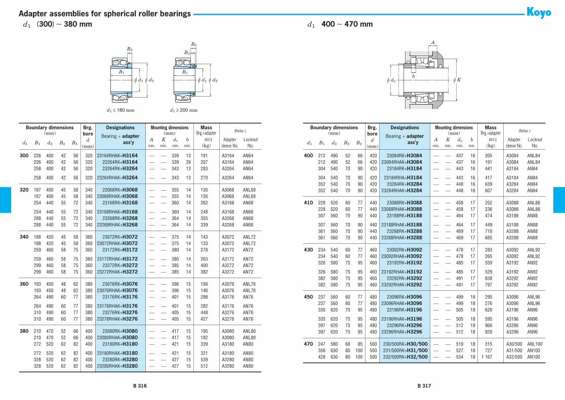
d1 ≤ 180 mm d1 ≥ 200 mm
B2
B3
B1 B1
u d1 u d2 u d1 u d2
B2
b
A
u de u K
Adapter assemblies for spherical roller bearings
300 226 400 42 56 320 23164RHAK+H3164 ⎯ ⎯ 339 13 191 A3164 AN64300 226 400 42 56 320 22264RK+H3164 ⎯ ⎯ 339 39 207 A3164 AN64300 258 400 42 56 320 23264RK+H3264 ⎯ ⎯ 343 13 283 A3264 AN64
300 258 400 42 56 320 23264RHAK+H3264 ⎯ ⎯ 343 13 270 A3264 AN64
320 187 400 45 58 340 23068RK+H3068 ⎯ ⎯ 355 14 135 A3068 ANL68320 187 400 45 58 340 23068RHAK+H3068 ⎯ ⎯ 355 14 126 A3068 ANL68320 254 440 55 72 340 23168RK+H3168 ⎯ ⎯ 360 14 262 A3168 AN68
320 254 440 55 72 340 23168RHAK+H3168 ⎯ ⎯ 360 14 248 A3168 AN68320 288 440 55 72 340 23268RK+H3268 ⎯ ⎯ 364 14 355 A3268 AN68320 288 440 55 72 340 23268RHAK+H3268 ⎯ ⎯ 364 14 339 A3268 AN68
340 188 420 45 58 360 23072RK+H3072 ⎯ ⎯ 375 14 143 A3072 ANL72340 188 420 45 58 360 23072RHAK+H3072 ⎯ ⎯ 375 14 133 A3072 ANL72340 259 460 58 75 360 23172RK+H3172 ⎯ ⎯ 380 14 278 A3172 AN72
340 259 460 58 75 360 23172RHAK+H3172 ⎯ ⎯ 380 14 263 A3172 AN72340 299 460 58 75 360 23272RK+H3272 ⎯ ⎯ 385 14 400 A3272 AN72340 299 460 58 75 360 23272RHAK+H3272 ⎯ ⎯ 385 14 382 A3272 AN72
360 193 450 48 62 380 23076RK+H3076 ⎯ ⎯ 396 15 156 A3076 ANL76360 193 450 48 62 380 23076RHAK+H3076 ⎯ ⎯ 396 15 146 A3076 ANL76360 264 490 60 77 380 23176RK+H3176 ⎯ ⎯ 401 15 298 A3176 AN76
360 264 490 60 77 380 23176RHAK+H3176 ⎯ ⎯ 401 15 282 A3176 AN76360 310 490 60 77 380 23276RK+H3276 ⎯ ⎯ 405 15 448 A3276 AN76360 310 490 60 77 380 23276RHAK+H3276 ⎯ ⎯ 405 15 427 A3276 AN76
380 210 470 52 66 400 23080RK+H3080 ⎯ ⎯ 417 15 195 A3080 ANL80380 210 470 52 66 400 23080RHAK+H3080 ⎯ ⎯ 417 15 182 A3080 ANL80380 272 520 62 82 400 23180RK+H3180 ⎯ ⎯ 421 15 339 A3180 AN80
380 272 520 62 82 400 23180RHAK+H3180 ⎯ ⎯ 421 15 321 A3180 AN80380 328 520 62 82 400 23280RK+H3280 ⎯ ⎯ 427 15 539 A3280 AN80380 328 520 62 82 400 23280RHAK+H3280 ⎯ ⎯ 427 15 512 A3280 AN80
Boundary dimensions Brg.bore
d(mm)
Designations Mounting dimensions Mass(Refer.)(mm)
Bearing + adapter ass'y
(mm) Brg.+adapter ass'y
d1 B1 d2 B2 B3A K de b Adapter
sleeve No.Locknut
No.min. min. min. min. (kg)
400 212 490 52 66 420 23084RK+H3084 ⎯ ⎯ 437 16 205 A3084 ANL84400 212 490 52 66 420 23084RHAK+H3084 ⎯ ⎯ 437 16 191 A3084 ANL84400 304 540 70 90 420 23184RK+H3184 ⎯ ⎯ 443 16 441 A3184 AN84
400 304 540 70 90 420 23184RHA+H3184 ⎯ ⎯ 443 16 417 A3184 AN84400 352 540 70 90 420 23284RK+H3284 ⎯ ⎯ 448 16 639 A3284 AN84400 352 540 70 90 420 23284RHAK+H3284 ⎯ ⎯ 448 16 607 A3284 AN84
410 228 520 60 77 440 23088RK+H3088 ⎯ ⎯ 458 17 252 A3088 ANL88410 228 520 60 77 440 23088RHAK+H3088 ⎯ ⎯ 458 17 236 A3088 ANL88410 307 560 70 90 440 23188RK+H3188 ⎯ ⎯ 464 17 474 A3188 AN88
410 307 560 70 90 440 23188RHAK+H3188 ⎯ ⎯ 464 17 449 A3188 AN88410 361 560 70 90 440 23288RK+H3288 ⎯ ⎯ 469 17 718 A3288 AN88410 361 560 70 90 440 23288RHAK+H3288 ⎯ ⎯ 469 17 685 A3288 AN88
430 234 540 60 77 460 23092RK+H3092 ⎯ ⎯ 478 17 283 A3092 ANL92430 234 540 60 77 460 23092RHAK+H3092 ⎯ ⎯ 478 17 265 A3092 ANL92430 326 580 75 95 460 23192RK+H3192 ⎯ ⎯ 485 17 559 A3192 AN92
430 326 580 75 95 460 23192RHAK+H3192 ⎯ ⎯ 485 17 529 A3192 AN92430 382 580 75 95 460 23292RK+H3292 ⎯ ⎯ 491 17 838 A3292 AN92430 382 580 75 95 460 23292RHAK+H3292 ⎯ ⎯ 491 17 797 A3292 AN92
450 237 560 60 77 480 23096RK+H3096 ⎯ ⎯ 499 18 295 A3096 ANL96450 237 560 60 77 480 23096RHAK+H3096 ⎯ ⎯ 499 18 276 A3096 ANL96450 335 620 75 95 480 23196RK+H3196 ⎯ ⎯ 505 18 628 A3196 AN96
450 335 620 75 95 480 23196RHAK+H3196 ⎯ ⎯ 505 18 595 A3196 AN96450 397 620 75 95 480 23296RK+H3296 ⎯ ⎯ 512 18 966 A3296 AN96450 397 620 75 95 480 23296RHAK+H3296 ⎯ ⎯ 512 18 920 A3296 AN96
470 247 580 68 85 500 230/500RK+H30/500 ⎯ ⎯ 519 18 315 A30/500 ANL100470 356 630 80 100 500 231/500RK+H31/500 ⎯ ⎯ 527 18 727 A31/500 AN100470 428 630 80 100 500 232/500RK+H32/500 ⎯ ⎯ 534 18 1 167 A32/500 AN100
Boundary dimensions Brg.bore
d(mm)
Designations Mounting dimensions Mass(Refer.)(mm)
Bearing + adapter ass'y
(mm) Brg.+adapter ass'y
d1 B1 d2 B2 B3A K de b Adapter
sleeve No.Locknut
No.min. min. min. min. (kg)
B 316 B 317
d1 (300) ∼ 380 mm d1 400 ∼ 470 mm

B1
G1
B2u d1
G
Withdrawal sleeves for spherical roller bearings
Boundary dimensions Brg.bore
d
(mm)
Designations Mass
(Refer.)
Applicablelocknut No.
(mm)
Bearing
+
withdrawal
sleeve
Brg.
+
withdrawal sleeve
d
1
B
1
B
2
G
1)
G
1
Screw size
(kg)
35
29 32 M45
×
1.5 6 40 22208RHRK
+
AH308
0.681 AN09
35
29 32 M45
×
1.5 6 40 21308RHK
+
AH308
0.860 AN09
35
40 43 M45
×
1.5 7 40 22308RHRK
+
AH2308
1.19 AN09
40
31 34 M50
×
1.5 6 45 22209RHRK
+
AH309
0.699 AN10
40
31 34 M50
×
1.5 6 45 21309RHK
+
AH309
1.14 AN10
40
44 47 M50
×
1.5 7 45 22309RHRK
+
AH2309
1.55 AN10
45
35 38 M55
×
2 7 50 22210RHRK
+
AHX310
0.771 AN11
45
35 38 M55
×
2 7 50 21310RHK
+
AHX310
1.49 AN11
45
50 53 M55
×
2 9 50 22310RHRK
+
AHX2310
2.09 AN11
50
37 40 M60
×
2 7 55 22211RHRK
+
AHX311
1.01 AN12
50
37 40 M60
×
2 7 55 21311RHK
+
AHX311
1.83 AN12
50
54 57 M60
×
2 10 55 22311RHRK
+
AHX2311
2.60 AN12
55
40 43 M65
×
2 8 60 22212RHRK
+
AHX312
1.35 AN13
55
40 43 M65
×
2 8 60 21312RHK
+
AHX312
2.27 AN13
55
58 61 M65
×
2 11 60 22312RHRK
+
AHX2312
3.29 AN13
60
42 45 M75
×
2 8 65 22213RHRK
+
AH313
1.77 AN15
60
42 45 M75
×
2 8 65 21313RHK
+
AH313
2.84 AN15
60
61 64 M75
×
2 12 65 22313RHRK
+
AH2313
3.98 AN15
65
43 47 M80
×
2 8 70 22214RHRK
+
AH314
1.89 AN16
65
43 47 M80
×
2 8 70 21314RHK
+
AH314
3.43 AN16
65
64 68 M80
×
2 12 70 22314RHRK
+
AHX2314
4.82 AN16
70
45 49 M85
×
2 8 75 22215RHRK
+
AH315
2.01 AN17
70
45 49 M85
×
2 8 75 21315RHK
+
AH315
4.07 AN17
70
68 72 M85
×
2 12 75 22315RHRK
+
AHX2315
5.87 AN17
75
48 52 M90
×
2 8 80 22216RHRK
+
AH316
2.49 AN18
75
48 52 M90
×
2 8 80 21316RHK
+
AH316
4.83 AN18
[Note] 1) Basic profile and dimensions of screw thread identified by prefix M are in accordance with JIS B 0205.Basic profile and dimensions of screw thread identified by prefix Tr are in accordance with JIS B 0216.
75
71 75 M90
×
2 12 80 22316RHRK
+
AHX2316
6.90 AN18
80
52 56 M95
×
2 9 85 22217RHRK
+
AHX317
3.12 AN19
80
52 56 M95
×
2 9 85 21317RHK
+
AHX317
5.68 AN19
80
74 78 M95
×
2 13 85 22317RHRK
+
AHX2317
7.98 AN19
85
53 57 M100
×
2 9 90 22218RHRK
+
AHX318
3.89 AN20
85
63 67 M100
×
2 10 90 23218RHK
+
AHX3218
5.08 AN20
85
53 57 M100
×
2 9 90 21318RHK
+
AHX318
6.58 AN20
85
79 83 M100
×
2 14 90 22318RHRK
+
AHX2318
9.41 AN20
90
57 61 M105
×
2 10 95 22219RHRK
+
AHX319
4.68 AN21
90
57 61 M105
×
2 10 95 21319RHK
+
AHX319
7.59 AN21
90
85 89 M105
×
2 16 95 22319RHRK
+
AHX2319
10.9 AN21
95
59 63 M110
×
2 10 100 22220RHRK
+
AHX320
5.58 AN22
95
73 77 M110
×
2 11 100 23220RHK
+
AHX3220
7.43 AN22
95
59 63 M110
×
2 10 100 21320RHK
+
AHX320
9.26 AN22
95
90 94 M110
×
2 16 100 22320RHRK
+
AHX2320
13.9 AN22
105
68 72 M120
×
2 11 110 23122RHK
+
AHX3122
6.30 AN24
105
82 91 M115
×
2 13 110 24122RHK30
+
AH24122
7.60 AN23
105
68 72 M120
×
2 11 110 22222RHRK
+
AHX3122
7.97 AN24
105
82 86 M125
×
2 11 110 23222RHK
+
AHX3222
10.5 AN25
105
63 67 M120
×
2 12 110 21322RHK
+
AHX322
12.3 AN24
105
98 102 M125
×
2 16 110 22322RHRK
+
AHX2322
19.1 AN25
115
60 64 M130
×
2 13 120 23024RHK
+
AHX3024
4.82 AN26
115
73 82 M125
×
2 13 120 24024RHK30
+
AH24024
5.99 AN25
115
75 79 M130
×
2 12 120 23124RHK
+
AHX3124
8.69 AN26
115
93 102 M130
×
2 13 120 24124RHK30
+
AH24124
11.0 AN26
115
75 79 M130
×
2 12 120 22224RHRK
+
AHX3124
10.1 AN26
Boundary dimensions Brg.bore
d
(mm)
Designations Mass
(Refer.)
Applicablelocknut No.
(mm)
Bearing
+
withdrawal
sleeve
Brg.
+
withdrawal sleeve
d
1
B
1
B
2
G
1)
G
1
Screw size
(kg)
[Note] 1) Basic profile and dimensions of screw thread identified by prefix M are in accordance with JIS B 0205.Basic profile and dimensions of screw thread identified by prefix Tr are in accordance with JIS B 0216.
B 318 B 319
d
1
35
∼
(
75
)
mm
d
1 (75) ∼ (115) mm

B1
G1
B2u d1
G
Withdrawal sleeves for spherical roller bearings
115 90 94 M135×2 13 120 23224RHK+AHX3224 13.1 AN27115 105 109 M135×2 17 120 22324RHRK+AHX2324 23.9 AN27
125 67 71 M140×2 14 130 23026RHK+AHX3026 6.90 AN28125 83 93 M135×2 14 130 24026RHK30+AH24026 8.74 AN27125 78 82 M140×2 12 130 23126RHK+AHX3126 9.52 AN28
125 94 104 M140×2 14 130 24126RHK30+AH24126 11.7 AN28125 78 82 M140×2 12 130 22226RHRK+AHX3126 12.4 AN28125 98 102 M145×2 15 130 23226RHK+AHX3226 15.6 AN29
125 115 119 M145×2 19 130 22326RHRK+AHX2326 29.9 AN29
135 68 73 M150×2 14 140 23028RHK+AHX3028 7.43 AN30135 83 93 M145×2 14 140 24028RHK30+AH24028 9.26 AN29135 83 88 M150×2 14 140 23128RHK+AHX3128 11.5 AN30
135 99 109 M150×2 14 140 24128RHK30+AH24128 14.1 AN30135 83 88 M150×2 14 140 22228RHRK+AHX3128 15.4 AN30135 104 109 M155×3 15 140 23228RHK+AHX3228 20.3 AN31
135 125 130 M155×3 20 140 22328RHK+AHX2328 35.0 AN31
145 72 77 M160×3 15 150 23030RHK+AHX3030 8.92 AN32145 90 101 M155×3 15 150 24030RHK30+AH24030 11.4 AN31145 96 101 M165×3 15 150 23130RHK+AHX3130 17.7 AN33
145 115 126 M160×3 15 150 24130RHK30+AH24130 21.2 AN32145 96 101 M165×3 15 150 22230RHRK+AHX3130 20.3 AN33145 114 119 M165×3 17 150 23230RHK+AHX3230 26.0 AN33
145 135 140 M165×3 24 150 22330RK+AHX2330 45.5 AN33145 135 140 M165×3 24 150 22330RHAK+AHX2330 42.2 AN33
150 77 82 M170×3 16 160 23032RHK+AH3032 11.5 AN34150 95 106 M170×3 15 160 24032RHK30+AH24032 15.0 AN34150 103 108 M180×3 16 160 23132RHK+AH3132 23.4 AN36
Boundary dimensions Brg.bore
d(mm)
Designations Mass (Refer.)
Applicablelocknut No.
(mm)Bearing + withdrawal
sleeve
Brg.+withdrawal sleeve
d1 B1 B2G 1)
G1Screw size (kg)
[Note] 1) Basic profile and dimensions of screw thread identified by prefix M are in accordance with JIS B 0205.Basic profile and dimensions of screw thread identified by prefix Tr are in accordance with JIS B 0216.
150 103 108 M180×3 16 160 22232RK+AH3132 26.1 AN36150 103 108 M180×3 16 160 22232RHAK+AH3132 24.6 AN36150 124 130 M180×3 20 160 23232RK+AH3232 35.1 AN36
150 124 130 M180×3 20 160 23232RHAK+AH3232 32.6 AN36150 140 146 M180×3 24 160 22332RK+AH2332 55.7 AN36150 140 146 M180×3 24 160 22332RHAK+AH2332 51.8 AN36
160 85 90 M180×3 17 170 23034RHK+AH3034 15.2 AN36160 106 117 M180×3 16 170 24034RHK30+AH24034 20.0 AN36160 104 109 M190×3 16 170 23134RHK+AH3134 24.6 AN38
160 125 136 M180×3 16 170 24134RRK30+AH24134 30.0 AN36160 104 109 M190×3 16 170 22234RK+AH3134 31.8 AN38160 104 109 M190×3 16 170 22234RHAK+AH3134 29.9 AN38
160 134 140 M190×3 24 170 23234RRK+AH3234 42.3 AN38160 134 140 M190×3 24 170 23234RHAK+AH3234 39.4 AN38160 146 152 M190×3 24 170 22334RK+AH2334 66.1 AN38
160 146 152 M190×3 24 170 22334RHAK+AH2334 61.4 AN38
170 92 98 M190×3 17 180 23036RHK+AH3036 19.7 AN38170 116 127 M190×3 16 180 24036RRK30+AH24036 26.1 AN38170 116 122 M200×3 19 180 23136RK+AH3136 31.7 AN40
170 116 122 M200×3 19 180 23136RHAK+AH3136 29.8 AN40170 134 145 M190×3 16 180 24136RRK30+AH24136 37.6 AN38170 134 145 M190×3 16 180 24136RHAK30+AH24136 34.9 AN38
170 105 110 M200×3 17 180 22236RK+AH2236 33.5 AN40170 105 110 M200×3 17 180 22236RHAK+AH2236 31.5 AN40170 140 146 M200×3 24 180 23236RRK+AH3236 45.1 AN40
170 140 146 M200×3 24 180 23236RHAK+AH3236 41.8 AN40170 154 160 M200×3 24 180 22336RK+AH2336 75.7 AN40170 154 160 M200×3 24 180 22336RHAK+AH2336 70.3 AN40
Boundary dimensions Brg.bore
d(mm)
Designations Mass (Refer.)
Applicablelocknut No.
(mm)Bearing + withdrawal
sleeve
Brg.+withdrawal sleeve
d1 B1 B2G 1)
G1Screw size (kg)
[Note] 1) Basic profile and dimensions of screw thread identified by prefix M are in accordance with JIS B 0205.Basic profile and dimensions of screw thread identified by prefix Tr are in accordance with JIS B 0216.
B 320 B 321
d1 (115) ∼ (150) mm d1 (150) ∼ 170 mm

B1
G1
B2u d1
G
Withdrawal sleeves for spherical roller bearings
180 96 102 Tr205×4 18 190 23038RK+AH3038 21.5 HNL41180 96 102 Tr205×4 18 190 23038RHAK+AH3038 19.9 HNL41180 118 131 M200×3 18 190 24038RRK30+AH24038 27.6 AN40
180 118 131 M200×3 18 190 24038RHAK30+AH24038 25.5 AN40180 125 131 Tr210×4 20 190 23138RK+AH3138 39.3 HN42180 125 131 Tr210×4 20 190 23138RHAK+AH3138 37.0 HN42
180 146 159 M200×3 18 190 24138RRK30+AH24138 46.7 AN40180 146 159 M200×3 18 190 24138RHAK30+AH24138 43.8 AN40180 112 117 Tr210×4 18 190 22238RK+AH2238 40.9 HN42
180 112 117 Tr210×4 18 190 22238RHAK+AH2238 38.4 HN42180 145 152 Tr210×4 25 190 23238RRK+AH3238 53.3 HN42180 145 152 Tr210×4 25 190 23238RHAK+AH3238 49.4 HN42
180 160 167 Tr210×4 26 190 22338RK+AH2338 89.0 HN42180 160 167 Tr210×4 26 190 22338RHAK+AH2338 82.6 HN42
190 102 108 Tr215×4 19 200 23040RK+AH3040 27.2 HNL43190 102 108 Tr215×4 19 200 23040RHAK+AH3040 25.1 HNL43190 127 140 Tr210×4 18 200 24040RRK30+AH24040 34.6 HN42
190 127 140 Tr210×4 18 200 24040RHAK30+AH24040 31.9 HN42190 134 140 Tr220×4 21 200 23140RRK+AH3140 47.9 HN44190 134 140 Tr220×4 21 200 23140RHAK+AH3140 45.0 HN44
190 158 171 Tr210×4 18 200 24140RRK30+AH24140 57.6 HN42190 158 171 Tr210×4 18 200 24140RHAK30+AH24140 53.8 HN42190 118 123 Tr220×4 19 200 22240RRK+AH2240 48.7 HN44
190 118 123 Tr220×4 19 200 22240RHAK+AH2240 45.7 HN44190 153 160 Tr220×4 25 200 23240RK+AH3240 64.7 HN44190 153 160 Tr220×4 25 200 23240RHAK+AH3240 60.1 HN44
190 170 177 Tr220×4 26 200 22340RK+AH2340 101 HN44190 170 177 Tr220×4 26 200 22340RHAK+AH2340 93.4 HN44
Boundary dimensions Brg.bore
d(mm)
Designations Mass (Refer.)
Applicablelocknut No.
(mm)Bearing + withdrawal
sleeve
Brg.+withdrawal sleeve
d1 B1 B2G 1)
G1Screw size (kg)
[Note] 1) Basic profile and dimensions of screw thread identified by prefix M are in accordance with JIS B 0205.Basic profile and dimensions of screw thread identified by prefix Tr are in accordance with JIS B 0216.
200 111 117 Tr235×4 20 220 23044RK+AH3044 38.0 HNL47200 111 117 Tr235×4 20 220 23044RHAK+AH3044 35.3 HNL47200 138 152 Tr230×4 20 220 24044RRK30+AH24044 48.1 ⎯
200 138 152 Tr230×4 20 220 24044RHAK30+AH24044 44.7 ⎯200 145 151 Tr240×4 23 220 23144RK+AH3144 63.6 HN48200 145 151 Tr240×4 23 220 23144RHAK+AH3144 60.0 HN48
200 170 184 Tr230×4 20 220 24144RRK30+AH24144 76.4 ⎯200 170 184 Tr230×4 20 220 24144RHAK30+AH24144 71.2 ⎯200 130 136 Tr240×4 20 220 22244RRK+AH2244 70.8 HN48
200 130 136 Tr240×4 20 220 22244RHAK+AH2244 66.6 HN48200 181 189 Tr240×4 30 220 23244RK+AH2344 95.1 HN48200 181 189 Tr240×4 30 220 23244RHAK+AH2344 88.5 HN48
200 181 189 Tr240×4 30 220 22344RK+AH2344 136 HN48200 181 189 Tr240×4 30 220 22344RHAK+AH2344 127 HN48
220 116 123 Tr260×4 21 240 23048RRK+AH3048 42.6 HNL52220 116 123 Tr260×4 21 240 23048RHAK+AH3048 39.7 HNL52220 138 153 Tr250×4 20 240 24048RRK30+AH24048 51.9 ⎯
220 138 153 Tr250×4 20 240 24048RHAK30+AH24048 48.0 ⎯220 154 161 Tr260×4 25 240 23148RRK+AH3148 77.6 HN52220 154 161 Tr260×4 25 240 23148RHAK+AH3148 73.1 HN52
220 180 195 Tr260×4 20 240 24148RRK30+AH24148 94.0 HN52220 180 195 Tr260×4 20 240 24148RHAK30+AH24148 87.9 HN52220 144 150 Tr260×4 21 240 22248RK+AH2248 94.3 HN52
220 144 150 Tr260×4 21 240 22248RHAK+AH2248 88.7 HN52220 189 197 Tr260×4 30 240 23248RRK+AH2348 126 HN52220 189 197 Tr260×4 30 240 23248RHAK+AH2348 117 HN52
220 189 197 Tr260×4 30 240 22348RK+AH2348 170 HN52220 189 197 Tr260×4 30 240 22348RHAK+AH2348 158 HN52
Boundary dimensions Brg.bore
d(mm)
Designations Mass (Refer.)
Applicablelocknut No.
(mm)Bearing + withdrawal
sleeve
Brg.+withdrawal sleeve
d1 B1 B2G 1)
G1Screw size (kg)
[Note] 1) Basic profile and dimensions of screw thread identified by prefix M are in accordance with JIS B 0205.Basic profile and dimensions of screw thread identified by prefix Tr are in accordance with JIS B 0216.
B 322 B 323
d1 180 ∼ 190 mm d1 200 ∼ 220 mm

B1
G1
B2u d1
G
Withdrawal sleeves for spherical roller bearings
240 128 135 Tr280×4 23 260 23052RK+AH3052 60.0 HNL56240 128 135 Tr280×4 23 260 23052RHAK+AH3052 55.6 HNL56240 162 178 Tr270×4 22 260 24052RRK30+AH24052 77.0 ⎯
240 162 178 Tr270×4 22 260 24052RHAK30+AH24052 71.2 ⎯240 172 179 Tr290×4 26 260 23152RK+AH3152 107 HN58240 172 179 Tr290×4 26 260 23152RHAK+AH3152 101 HN58
240 202 218 Tr280×4 22 260 24152RRK30+AH24152 128 ⎯240 202 218 Tr280×4 22 260 24152RHAK30+AH24152 120 ⎯240 155 161 Tr290×4 23 260 22252RK+AH2252 122 HN58
240 155 161 Tr290×4 23 260 22252RHAK+AH2252 115 HN58240 205 213 Tr290×4 30 260 23252RK+AH2352 164 HN58240 205 213 Tr290×4 30 260 23252RHAK+AH2352 153 HN58
240 205 213 Tr290×4 30 260 22352RK+AH2352 212 HN58240 205 213 Tr290×4 30 260 22352RHAK+AH2352 197 HN58
260 131 139 Tr300×4 24 280 23056RK+AH3056 64.9 HNL60260 131 139 Tr300×4 24 280 23056RHAK+AH3056 60.2 HNL60260 162 179 Tr290×4 22 280 24056RRK30+AH24056 81.9 HN58
260 162 179 Tr290×4 22 280 24056RHAK30+AH24056 75.7 HN58260 175 183 Tr310×5 28 280 23156RRK+AH3156 114 HN62260 175 183 Tr310×5 28 280 23156RHAK+AH3156 108 HN62
260 202 219 Tr300×4 22 280 24156RRK30+AH24156 136 ⎯260 202 219 Tr300×4 22 280 24156RHAK30+AH24156 128 ⎯260 155 163 Tr310×5 24 280 22256RK+AH2256 127 HN62
260 155 163 Tr310×5 24 280 22256RHAK+AH2256 119 HN62260 212 220 Tr310×5 30 280 23256RK+AH2356 175 HN62260 212 220 Tr310×5 30 280 23256RHAK+AH2356 163 HN62
260 212 220 Tr310×5 30 280 22356RK+AH2356 247 HN62260 212 220 Tr310×5 30 280 22356RHAK+AH2356 230 HN62
Boundary dimensions Brg.bore
d(mm)
Designations Mass (Refer.)
Applicablelocknut No.
(mm)Bearing + withdrawal
sleeve
Brg.+withdrawal sleeve
d1 B1 B2G 1)
G1Screw size (kg)
[Note] 1) Basic profile and dimensions of screw thread identified by prefix M are in accordance with JIS B 0205.Basic profile and dimensions of screw thread identified by prefix Tr are in accordance with JIS B 0216.
280 145 153 Tr320×5 26 300 23060RK+AH3060 88.1 HNL64280 145 153 Tr320×5 26 300 23060RHAK+AH3060 81.2 HNL64280 184 202 Tr310×5 24 300 24060RRK30+AH24060 112 HN62
280 184 202 Tr310×5 24 300 24060RHAK30+AH24060 105 HN62280 192 200 Tr330×5 30 300 23160RRK+AH3160 149 HN66280 192 200 Tr330×5 30 300 23160RHAK+AH3160 140 HN66
280 224 242 Tr320×5 24 300 24160RRK30+AH24160 180 ⎯280 224 242 Tr320×5 24 300 24160RHAK30+AH24160 168 ⎯280 170 178 Tr330×5 26 300 22260RK+AH2260 160 HN66
280 170 178 Tr330×5 26 300 22260RHAK+AH2260 150 HN66280 228 236 Tr330×5 34 300 23260RK+AH3260 223 HN66280 228 236 Tr330×5 34 300 23260RHAK+AH3260 208 HN66
300 149 157 Tr345×5 27 320 23064RK+AH3064 94.8 HNL69300 149 157 Tr345×5 27 320 23064RHAK+AH3064 88.1 HNL69300 184 202 Tr330×5 24 320 24064RRK30+AH24064 120 HN66
300 184 202 Tr330×5 24 320 24064RHAK30+AH24064 108 HN66300 209 217 Tr350×5 31 320 23164RK+AH3164 191 HN70300 209 217 Tr350×5 31 320 23164RHAK+AH3164 180 HN70
300 242 260 Tr340×5 24 320 24164RRK30+AH24164 226 ⎯300 242 260 Tr340×5 24 320 24164RHAK30+AH24164 217 ⎯300 180 190 Tr350×5 27 320 22264RK+AH2264 191 HN70
300 246 254 Tr350×5 36 320 23264RK+AH3264 280 HN70300 246 254 Tr350×5 36 320 23264RHAK+AH3264 260 HN70
320 162 171 Tr365×5 28 340 23068RK+AH3068 125 HNL73320 162 171 Tr365×5 28 340 23068RHAK+AH3068 115 HNL73320 225 234 Tr370×5 33 340 23168RK+AH3168 239 HN74
320 225 234 Tr370×5 33 340 23168RHAK+AH3168 225 HN74320 269 288 Tr360×5 26 340 24168RRK30+AH24168 293 ⎯
Boundary dimensions Brg.bore
d(mm)
Designations Mass (Refer.)
Applicablelocknut No.
(mm)Bearing + withdrawal
sleeve
Brg.+withdrawal sleeve
d1 B1 B2G 1)
G1Screw size (kg)
[Note] 1) Basic profile and dimensions of screw thread identified by prefix M are in accordance with JIS B 0205.Basic profile and dimensions of screw thread identified by prefix Tr are in accordance with JIS B 0216.
B 324 B 325
d1 240 ∼ 260 mm d1 280 ∼ (320) mm

B1
G1
B2u d1
G
Withdrawal sleeves for spherical roller bearings
320 269 288 Tr360×5 26 340 24168RHAK30+AH24168 282 ⎯320 264 273 Tr370×5 38 340 23268RK+AH3268 342 HN74320 264 273 Tr370×5 38 340 23268RHAK+AH3268 317 HN74
340 167 176 Tr385×5 30 360 23072RK+AH3072 132 HNL77340 167 176 Tr385×5 30 360 23072RHAK+AH3072 122 HNL77340 229 238 Tr400×5 35 360 23172RK+AH3172 254 HN80
340 232 238 Tr400×5 35 360 23172RHAK+AH3172 239 HN80340 269 289 Tr380×5 26 360 24172RK30+AH24172 313 ⎯340 269 289 Tr380×5 26 360 24172RHAK30+AH24172 300 ⎯
340 274 283 Tr400×5 40 360 23272RK+AH3272 388 HN80340 274 283 Tr400×5 40 360 23272RHAK+AH3272 360 HN80
360 170 180 Tr410×5 31 380 23076RK+AH3076 141 HNL82360 170 180 Tr410×5 31 380 23076RHAK+AH3076 131 HNL82360 232 242 Tr420×5 36 380 23176RK+AH3176 269 HN84
360 240 242 Tr420×5 36 380 23176RHAK+AH3176 253 HN84360 271 291 Tr400×5 28 380 24176RK30+AH24176 328 HN80360 271 291 Tr400×5 28 380 24176RHAK30+AH24176 314 HN80
360 284 294 Tr420×5 42 380 23276RK+AH3276 432 HN84360 284 294 Tr420×5 42 380 23276RHAK+AH3276 400 HN84
380 183 193 Tr430×5 33 400 23080RK+AH3080 178 HNL86380 183 193 Tr430×5 33 400 23080RHAK+AH3080 165 HNL86380 240 250 Tr440×5 38 400 23180RK+AH3180 305 HN88
380 266 250 Tr440×5 38 400 23180RHAK+AH3180 287 HN88380 278 298 Tr420×5 28 400 24180RK30+AH24180 368 HN84380 278 298 Tr420×5 28 400 24180RHAK30+AH24180 352 HN84
380 302 312 Tr440×5 44 400 23280RK+AH3280 521 HN88380 302 312 Tr440×5 44 400 23280RHAK+AH3280 480 HN88
Boundary dimensions Brg.bore
d(mm)
Designations Mass (Refer.)
Applicablelocknut No.
(mm)Bearing + withdrawal
sleeve
Brg.+withdrawal sleeve
d1 B1 B2G 1)
G1Screw size (kg)
[Note] 1) Basic profile and dimensions of screw thread identified by prefix M are in accordance with JIS B 0205.Basic profile and dimensions of screw thread identified by prefix Tr are in accordance with JIS B 0216.
400 186 196 Tr450×5 34 420 23084RK+AH3084 188 HNL90400 186 196 Tr450×5 34 420 23084RHAK+AH3084 174 HNL90400 266 276 Tr460×5 40 420 23184RK+AH3184 399 HN92
400 270 276 Tr460×5 40 420 23184RHAK+AH3184 375 HN92400 321 331 Tr460×5 46 420 23284RK+AH3284 673 HN92400 321 331 Tr460×5 46 420 23284RHAK+AH3284 568 HN92
420 194 205 Tr470×5 35 440 23088RK+AHX3088 215 HNL94420 194 205 Tr470×5 35 440 23088RHAK+AHX3088 199 HNL94420 270 281 Tr480×5 42 440 23188RK+AHX3188 416 HN96
420 285 281 Tr480×5 42 440 23188RHAK+AHX3188 391 HN96420 330 341 Tr480×5 48 440 23288RK+AHX3288 678 HN96420 330 341 Tr480×5 48 440 23288RHAK+AHX3288 627 HN96
440 202 213 Tr490×5 37 460 23092RK+AHX3092 244 HNL98440 202 213 Tr490×5 37 460 23092RHAK+AHX3092 226 HNL98440 285 296 Tr510×6 43 460 23192RK+AHX3192 494 HN102
440 295 296 Tr510×6 43 460 23192RHAK+AHX3192 464 HN102440 349 360 Tr510×6 50 460 23292RK+AHX3292 795 HN102440 349 360 Tr510×6 50 460 23292RHAK+AHX3292 733 HN102
460 205 217 Tr520×6 38 480 23096RK+AHX3096 257 HNL104460 205 217 Tr520×6 38 480 23096RHAK+AHX3096 238 HNL104460 295 307 Tr530×6 45 480 23196RK+AHX3196 551 HN106
460 313 307 Tr530×6 45 480 23196RHAK+AHX3196 518 HN106460 364 376 Tr530×6 52 480 23296RK+AHX3296 914 HN106460 364 376 Tr530×6 52 480 23296RHAK+AHX3296 844 HN106
480 209 221 Tr540×6 40 500 230/500RK+AHX30/500 271 HNL108480 313 325 Tr550×6 47 500 231/500RK+AHX31/500 648 HN110480 393 405 Tr550×6 54 500 232/500RK+AHX32/500 1 015 HN110
Boundary dimensions Brg.bore
d(mm)
Designations Mass (Refer.)
Applicablelocknut No.
(mm)Bearing + withdrawal
sleeve
Brg.+withdrawal sleeve
d1 B1 B2G 1)
G1Screw size (kg)
[Note] 1) Basic profile and dimensions of screw thread identified by prefix M are in accordance with JIS B 0205.Basic profile and dimensions of screw thread identified by prefix Tr are in accordance with JIS B 0216.
B 326 B 327
d1 (320) ∼ 380 mm d1 400 ∼ 480 mm

B 328 B 329
Thrust ball bearings Single direction thrust ball bearings
Double direction thrust ball bearings
Bore diameter 10 – 360 mm
Bore diameter 10 – 190 mm
Thrust ball bearings are divided into single and double direction types. The former is able to accommodate axial load in one direction, while the latter is able to accommodate it in both directions.
Neither is suitable for applications that involve radial load or high-speed rotation.
Bearings whose housing race back face is spherical (with a spherical back face or aligning seat race) are designed with a self-aligning capability and can accommodate the effects of inaccurate mounting.
Boundarydimensions As specified in JIS B 1512.
Tolerances As specified in JIS B 1514-2.(refer to Table 7-9 on p. A 74.)
Recommendedfits Refer to Table 9-8 on p. A 98.
Standard cages *Pressed steel cage (supplementary code : //)
*Copper alloy or carbon steel machinedcage (supplementary code : FY or FC)
*Polyamide resin molded cage (supplementary code : MG)
Application of standard cages
Bearing series Molded cage Pressed cage Machined cage
511 51100 − 51107 51108 − 51132 51134 − 51172
512 51200 − 51207 51208 − 51224 51226 − 51272532 53200 − 53207 53208 − 53224 53226 − 53272532 U 53200U − 53207U 53208U − 53224U 53226U − 53272U513 − 51305 − 51313 51314 − 51340533 − 53305 − 53313 53314 − 53340533 U − 53305U − 53313U 53314U − 53340U514 − 51405 − 51416 51417 − 51436534 − 53405 − 53416 53417 − 53420534 U − 53405U − 53416U 53417U − 53420U522 − 52202 − 52224 52226 − 52244542 − 54202 − 54224 54226 − 54244542 U − 54205U − 54224U 54226U − 54244U523 − 52305 − 52313 52314 − 52340543 − 54305 − 54313 54314 − 54324543 U − 54305U − 54313U 54314U − 54324U524 − 52405 − 52411 52412 − 52444544 − 54405 − 54411 54412 − 54420544 U − 54405U − 54411U 54412U − 54420U
Required minimum axial load
A certain degree of load is necessary in order for bearings to operate satisfactorily.(refer to p. A 116.)
Allowablemisalignment
Misalignment not allowed.(for flat back face type.)
Equivalent axial load
Dynamic equivalent axial load Pa = FaStatic equivalent axial load P0a = Fa

With flatback faces
With sphericalback face
With aligningseat race
T T2
u D1
u D
u d1
u d
T1
AR
u D1
u D
u d1u d
rr
C
u D3
u D2rr
u Da
u da
ra
u Da
u da
ra
u Da
ra
u da
ra ra
Single direction thrust ball bearings
Boundary dimensions Basic load ratings
Fatigue
Limiting speeds Bearing No. Dimensions
Mounting dimensions
(Refer.)
Mass
(kg)(mm) (kN)
load limit
(min
−
1
) (mm) (mm)
d D T T
1
T
2
rC
a
C
0a
(kN)
Grease lub.
Oil lub.
With flatback faces
With sphericalback face
With aligningseat race
d
1
D
1
D
2
D
3
A R Cd
a
D
a
r
a
With flatback faces
With sphericalback face
With aligningseat race
min.
C
u
max. min. min. max. max.
10
24 9
⎯ ⎯
0.3 12.5 14.0 0.630 6 500 10 000
51100
⎯
⎯
24 11
⎯ ⎯ ⎯ ⎯ ⎯
18 16 0.3 0.020
⎯ ⎯
10
26 11 11.6 13 0.6 15.8 17.1 0.770 5 700 8 800
51200 53200
53200U
26 12 18 28 8.5 22 3.5 20 16 0.6 0.030 0.029 0.037
12
26 9
⎯ ⎯
0.3 12.9 14.0 0.690 6 500 10 000
51101
⎯
⎯
26 13
⎯ ⎯ ⎯ ⎯ ⎯
20 18 0.3 0.022
⎯ ⎯
12
28 11 11.4 13 0.6 16.5 19.0 0.860 5 400 8 300
51201 53201
53201U
28 14 20 30 11.5 25 3.5 22 18 0.6 0.034 0.031 0.043
15
28 9
⎯ ⎯
0.3 13.2 15.4 0.760 6 100 9 400
51102
⎯
⎯
28 16
⎯ ⎯ ⎯ ⎯ ⎯
23 20 0.3 0.024
⎯ ⎯
15
32 12 13.3 15 0.6 20.8 24.8 1.10 4 900 7 500
51202 53202
53202U
32 17 24 35 12 28 4 25 22 0.6 0.046 0.048 0.062
17
30 9
⎯ ⎯
0.3 13.5 18.2 0.820 6 100 9 400
51103
⎯
⎯
30 18
⎯ ⎯ ⎯ ⎯ ⎯
25 22 0.3 0.028
⎯ ⎯
17
35 12 13.2 15 0.6 21.5 27.3 1.25 4 900 7 500
51203 53203
53203U
35 19 26 38 16 32 4 28 24 0.6 0.053 0.055 0.070
20
35 10
⎯ ⎯
0.3 17.8 24.7 1.10 5 100 7 900
51104
⎯
⎯
35 21
⎯ ⎯ ⎯ ⎯ ⎯
29 26 0.3 0.040
⎯ ⎯
20
40 14 14.7 17 0.6 27.9 37.7 1.70 3 900 6 000
51204 53204
53204U
40 22 30 42 18 36 5 32 28 0.6 0.082 0.080 0.100
25
42 11
⎯ ⎯
0.6 24.4 37.2 1.70 4 400 6 800
51105
⎯
⎯
42 26
⎯ ⎯ ⎯ ⎯ ⎯
35 32 0.6 0.059
⎯ ⎯
25
47 15 16.7 19 0.6 34.6 50.4 2.30 3 600 5 500
51205 53205
53205U
47 27 36 50 19 40 5.5 38 34 0.6 0.120 0.120 0.152
25
52 18 19.8 22 1 44.7 61.4 2.75 3 100 4 800
51305 53305
53305U
52 27 38 55 21 45 6 41 36 1 0.180 0.180 0.224
25
60 24 26.4 29 1 69.5 89.4 4.05 2 600 4 000
51405 53405
53405U
60 27 42 62 19 50 8 46 39 1 0.340 0.350 0.442
30
47 11
⎯ ⎯
0.6 25.5 42.2 1.90 4 300 6 600
51106
⎯
⎯
47 32
⎯ ⎯ ⎯ ⎯ ⎯
40 37 0.6 0.068
⎯ ⎯
30
52 16 17.8 20 0.6 36.7 58.2 2.65 3 400 5 200
51206 53206
53206U
52 32 42 55 22 45 5.5 43 39 0.6 0.150 0.160 0.193
30
60 21 22.6 25 1 53.5 78.7 3.55 2 700 4 200
51306 53306
53306U
60 32 45 62 22 50 7 48 42 1 0.270 0.270 0.326
30
70 28 30.1 33 1 91.0 126 5.70 2 200 3 400
51406 53406
53406U
70 32 50 75 20 56 9 54 46 1 0.530 0.530 0.660
35
52 12
⎯ ⎯
0.6 25.5 47.2 2.00 3 900 6 000
51107
⎯
⎯
52 37
⎯ ⎯ ⎯ ⎯ ⎯
45 42 0.6 0.090
⎯ ⎯
35
62 18 19.9 22 1 48.9 78.2 3.55 2 900 4 500
51207 53207
53207U
62 37 48 65 24 50 7 51 46 1 0.220 0.220 0.277
35
68 24 25.6 28 1 69.3 105 4.75 2 400 3 700
51307 53307
53307U
68 37 52 72 24 56 7.5 55 48 1 0.390 0.400 0.484
35
80 32 34 37 1.1 109 155 7.00 1 900 2 900
51407 53407
53407U
80 37 58 85 23 64 10 62 53 1 0.790 0.790 0.960
40
60 13
⎯ ⎯
0.6 33.6 62.8 2.85 3 400 5 300
51108
⎯
⎯
60 42
⎯ ⎯ ⎯ ⎯ ⎯
52 48 0.6 0.120
⎯ ⎯
40
68 19 20.3 23 1 58.7 98.3 4.45 2 700 4 200
51208 53208
53208U
68 42 55 72 28.5 56 7 57 51 1 0.270 0.270 0.340
40
78 26 28.5 31 1 86.6 135 6.05 2 100 3 300
51308 53308
53308U
78 42 60 82 28 64 8.5 63 55 1 0.550 0.570 0.690
[Remark] Standard cage types used for the above bearings are described earlier in this section.
B 330 B 331
d
10
∼
(
40
)
mm

With flatback faces
With sphericalback face
With aligningseat race
T T2
u D1
u D
u d1
u d
T1
AR
u D1
u D
u d1u d
rr
C
u D3
u D2rr
u Da
u da
ra
u Da
u da
ra
u Da
ra
u da
ra ra
Single direction thrust ball bearings
40
90 36 38.2 42 1.1 141 205 9.25 1 700 2 600
51408 53408
53408U
90 42 65 95 26 72 12 70 60 1 1.14 1.12 1.37
45
65 14
⎯ ⎯
0.6 34.8 69.1 3.10 3 200 5 000
51109
⎯
⎯
65 47
⎯ ⎯ ⎯ ⎯ ⎯
57 53 0.6 0.150
⎯ ⎯
45
73 20 21.3 24 1 59.7 105 4.75 2 600 4 000
51209 53209
53209U
73 47 60 78 26 56 7.5 62 56 1 0.320 0.310 0.397
45
85 28 30.1 33 1 100 163 7.40 1 900 3 000
51309 53309
53309U
85 47 65 90 25 64 10 69 61 1 0.690 0.680 0.850
45
100 39 42.4 46 1.1 162 242 10.9 1 500 2 300
51409 53409
53409U
100 47 72 105 29 80 12.5 78 67 1 1.47 1.50 1.82
50
70 14
⎯ ⎯
0.6 35.9 75.4 3.40 3 100 4 800
51110
⎯
⎯
70 52
⎯ ⎯ ⎯ ⎯ ⎯
62 58 0.6 0.160
⎯ ⎯
50
78 22 23.5 26 1 60.6 111 5.05 2 300 3 600
51210 53210
53210U
78 52 62 82 32.5 64 7.5 67 61 1 0.390 0.380 0.480
50
95 31 34.3 37 1.1 121 202 9.10 1 800 2 700
51310 53310
53310U
95 52 72 100 28 72 11 77 68 1 1.00 1.01 1.24
50
110 43 45.6 50 1.5 185 283 12.8 1 400 2 100
51410 53410
53410U
110 52 80 115 35 90 14 86 74 1.5 1.99 1.97 2.38
55
78 16
⎯ ⎯
0.6 43.5 93.1 4.20 2 800 4 300
51111
⎯
⎯
78 57
⎯ ⎯ ⎯ ⎯ ⎯
69 64 0.6 0.240
⎯ ⎯
55
90 25 27.3 30 1 86.7 159 7.20 2 100 3 200
51211 53211
53211U
90 57 72 95 35 72 9 76 69 1 0.610 0.620 0.770
55
105 35 39.3 42 1.1 149 246 11.1 1 600 2 400
51311 53311
53311U
105 57 80 110 30 80 11.5 85 75 1 1.34 1.41 1.69
55
120 48 50.5 55 1.5 223 359 16.2 1 200 1 900
51411 53411
53411U
120 57 88 125 28 90 15.5 94 81 1.5 2.64 2.57 3.10
60
85 17
⎯ ⎯
1 51.8 113 5.10 2 600 4 000
51112
⎯
⎯
85 62
⎯ ⎯ ⎯ ⎯ ⎯
75 70 1 0.290
⎯ ⎯
60
95 26 28 31 1 92.0 179 8.05 1 900 3 000
51212 53212
53212U
95 62 78 100 32.5 72 9 81 74 1 0.690 0.690 0.850
60
110 35 38.3 42 1.1 154 267 12.1 1 500 2 300
51312 53312
53312U
110 62 85 115 41 90 11.5 90 80 1 1.43 1.47 1.78
60
130 51 54 58 1.5 267 437 19.7 1 100 1 700
51412 53412
53412U
130 62 95 135 34 100 16 102 88 1.5 3.51 3.44 4.13
65
90 18
⎯ ⎯
1 52.1 117 5.30 2 400 3 700
51113
⎯
⎯
90 67
⎯ ⎯ ⎯ ⎯ ⎯
80 75 1 0.340
⎯ ⎯
65
100 27 28.7 32 1 93.6 189 8.50 1 900 2 900
51213 53213
53213U
100 67 82 105 40 80 9 86 79 1 0.770 0.750 0.930
65
115 36 39.4 43 1.1 159 287 13.0 1 400 2 200
51313 53313
53313U
115 67 90 120 38.5 90 12.5 95 85 1 1.57 1.61 1.95
65
140 56 60.2 65 2 290 493 22.0 1 000 1 600
51413 53413 53413U 140 68 100 145 40 112 17.5 110 95 2 4.47 4.47 5.28
70 95 18 ⎯ ⎯ 1 53.8 127 5.70 2 300 3 600 51114 ⎯ ⎯ 95 72 ⎯ ⎯ ⎯ ⎯ ⎯ 85 80 1 0.360 ⎯ ⎯70 105 27 28.8 32 1 95.2 199 8.95 1 800 2 800 51214 53214 53214U 105 72 88 110 38 80 9 91 84 1 0.810 0.800 0.99070 125 40 44.2 48 1.1 167 291 13.1 1 300 2 000 51314 53314 53314U 125 72 98 130 43 100 13 103 92 1 2.06 2.15 2.56
70 150 60 63.6 69 2 312 553 23.8 940 1 450 51414 53414 53414U 150 73 110 155 34 112 19.5 118 102 2 5.48 5.38 6.37
Boundary dimensions Basic load ratings Fatigue Limiting speeds Bearing No. Dimensions Mounting dimensions (Refer.) Mass (kg)(mm) (kN) load limit (min−1) (mm) (mm)
d D T T1 T2r
Ca C0a(kN) Grease
lub.Oil lub.
With flatback faces
With sphericalback face
With aligningseat race
d1 D1 D2 D3 A R Cda Da ra With flat
back facesWith spherical
back faceWith aligning
seat racemin. Cu max. min. min. max. max.
[Remark] Standard cage types used for the above bearings are described earlier in this section.
B 332 B 333
d (40) ∼ 70 mm

With flatback faces
With sphericalback face
With aligningseat race
T T2
u D1
u D
u d1
u d
T1
AR
u D1
u D
u d1u d
rr
C
u D3
u D2rr
u Da
u da
ra
u Da
u da
ra
u Da
ra
u da
ra ra
Single direction thrust ball bearings
75 100 19 ⎯ ⎯ 1 55.5 136 6.15 2 200 3 400 51115 ⎯ ⎯ 100 77 ⎯ ⎯ ⎯ ⎯ ⎯ 90 85 1 0.420 ⎯ ⎯75 110 27 28.3 32 1 96.7 209 9.40 1 800 2 700 51215 53215 53215U 110 77 92 115 49 90 9.5 96 89 1 0.860 0.850 1.0675 135 44 48.1 52 1.5 192 339 15.0 1 200 1 900 51315 53315 53315U 135 77 105 140 37 100 15 111 99 1.5 2.68 2.72 3.27
75 160 65 69 75 2 315 560 23.3 880 1 350 51415 53415 53415U 160 78 115 165 42 125 21 125 110 2 6.75 6.64 7.87
80 105 19 ⎯ ⎯ 1 55.8 141 6.35 2 100 3 300 51116 ⎯ ⎯ 105 82 ⎯ ⎯ ⎯ ⎯ ⎯ 95 90 1 0.430 ⎯ ⎯80 115 28 29.5 33 1 98.1 218 9.85 1 700 2 600 51216 53216 53216U 115 82 98 120 46 90 10 101 94 1 0.950 0.930 1.1580 140 44 47.6 52 1.5 200 368 15.8 1 200 1 800 51316 53316 53316U 140 82 110 145 50 112 15 116 104 1.5 2.82 2.86 3.43
80 170 68 72.2 78 2.1 337 621 25.1 810 1 250 51416 53416 53416U 170 83 125 175 36 125 22 133 117 2 7.97 7.84 9.22
85 110 19 ⎯ ⎯ 1 57.4 150 6.80 2 100 3 200 51117 ⎯ ⎯ 110 87 ⎯ ⎯ ⎯ ⎯ ⎯ 100 95 1 0.460 ⎯ ⎯85 125 31 33.1 37 1 119 264 11.6 1 500 2 300 51217 53217 53217U 125 88 105 130 52 100 11 109 101 1 1.29 1.28 1.5785 150 49 53.1 58 1.5 232 419 17.5 1 100 1 700 51317 53317 53317U 150 88 115 155 43 112 17.5 124 111 1.5 3.66 3.63 4.44
85 180 72 77 83 2.1 384 753 29.5 780 1 200 51417 53417 53417U 177 88 130 185 47 140 23 141 124 2 9.29 9.20 10.8
90 120 22 ⎯ ⎯ 1 74.6 190 8.40 1 900 2 900 51118 ⎯ ⎯ 120 92 ⎯ ⎯ ⎯ ⎯ ⎯ 108 102 1 0.680 ⎯ ⎯90 135 35 38.5 42 1.1 146 326 13.9 1 400 2 100 51218 53218 53218U 135 93 110 140 45 100 13.5 117 108 1 1.77 1.77 2.1990 155 50 54.6 59 1.5 242 454 18.5 1 000 1 600 51318 53318 53318U 155 93 120 160 40 112 18 129 116 1.5 3.88 3.87 4.71
90 190 77 81.2 88 2.1 409 826 31.5 710 1 100 51418 53418 53418U 187 93 140 195 40 140 25.5 149 131 2 11.0 10.7 12.6
100 135 25 ⎯ ⎯ 1 106 268 11.2 1 600 2 500 51120 ⎯ ⎯ 135 102 ⎯ ⎯ ⎯ ⎯ ⎯ 121 114 1 0.990 ⎯ ⎯100 150 38 40.9 45 1.1 183 410 16.6 1 200 1 900 51220 53220 53220U 150 103 125 155 52 112 14 130 120 1 2.36 2.34 2.84100 170 55 59.2 64 1.5 296 595 23.2 940 1 450 51320 53320 53320U 170 103 135 175 46 125 18 142 128 1.5 5.11 5.10 6.05
100 210 85 90 98 3 460 983 35.7 620 950 51420 53420 53420U 205 103 155 220 50 160 27 165 145 2.5 14.6 14.5 17.4
110 145 25 ⎯ ⎯ 1 109 288 11.5 1 600 2 400 51122 ⎯ ⎯ 145 112 ⎯ ⎯ ⎯ ⎯ ⎯ 131 124 1 1.08 ⎯ ⎯110 160 38 40.2 45 1.1 191 450 17.6 1 200 1 800 51222 53222 53222U 160 113 135 165 65 125 14 140 130 1 2.57 2.50 3.06110 190 63 67.2 72 2 334 704 25.9 810 1 250 51322 53322 53322U 187 113 150 195 51 140 20.5 158 142 2 7.72 7.63 8.90
110 230 95 ⎯ ⎯ 3 474 1 070 37.1 550 850 51422 ⎯ ⎯ 225 113 ⎯ ⎯ ⎯ ⎯ ⎯ 181 159 2.5 19.8 ⎯ ⎯
120 155 25 ⎯ ⎯ 1 111 305 11.9 1 500 2 300 51124 ⎯ ⎯ 155 122 ⎯ ⎯ ⎯ ⎯ ⎯ 141 134 1 1.16 ⎯ ⎯
Boundary dimensions Basic load ratings Fatigue Limiting speeds Bearing No. Dimensions Mounting dimensions (Refer.) Mass (kg)(mm) (kN) load limit (min−1) (mm) (mm)
d D T T1 T2r
Ca C0a(kN) Grease
lub.Oil lub.
With flatback faces
With sphericalback face
With aligningseat race
d1 D1 D2 D3 A R Cda Da ra With flat
back facesWith spherical
back faceWith aligning
seat racemin. Cu max. min. min. max. max.
[Remark] Standard cage types used for the above bearings are described earlier in this section.
B 334 B 335
d 75 ∼ (120) mm

With flatback faces
With sphericalback face
With aligningseat race
T T2
u D1
u D
u d1
u d
T1
AR
u D1
u D
u d1u d
rr
C
u D3
u D2rr
u Da
u da
ra
u Da
u da
ra
u Da
ra
u da
ra ra
Single direction thrust ball bearings
120 170 39 40.8 46 1.1 192 470 17.7 1 100 1 700 51224 53224 53224U 170 123 145 175 61 125 15 150 140 1 2.86 2.81 3.46120 210 70 74.1 80 2.1 389 869 30.5 710 1 100 51324 53324 53324U 205 123 165 220 63 160 22 173 157 2 10.6 10.4 12.4120 250 102 ⎯ ⎯ 4 601 1 460 48.5 520 800 51424 ⎯ ⎯ 245 123 ⎯ ⎯ ⎯ ⎯ ⎯ 196 174 3 25.0 ⎯ ⎯
130 170 30 ⎯ ⎯ 1 130 350 13.0 1 300 2 000 51126 ⎯ ⎯ 170 132 ⎯ ⎯ ⎯ ⎯ ⎯ 154 146 1 1.87 ⎯ ⎯130 190 45 47.9 53 1.5 254 620 22.2 970 1 500 51226 53226 53226U 187 133 160 195 67 140 17 166 154 1.5 4.09 3.98 4.88130 225 75 80.3 86 2.1 413 958 32.5 650 1 000 51326 53326 53326U 220 134 177 235 53 160 26 186 169 2 13.0 12.7 15.2
130 270 110 ⎯ ⎯ 4 623 1 540 49.0 490 750 51426 ⎯ ⎯ 265 134 ⎯ ⎯ ⎯ ⎯ ⎯ 212 188 3 31.4 ⎯ ⎯
140 180 31 ⎯ ⎯ 1 133 375 13.5 1 200 1 900 51128 ⎯ ⎯ 178 142 ⎯ ⎯ ⎯ ⎯ ⎯ 164 156 1 2.02 ⎯ ⎯140 200 46 48.6 55 1.5 234 650 19.6 940 1 450 51228 53228 53228U 197 143 170 210 87 160 17 176 164 1.5 4.46 4.35 5.89140 240 80 84.9 92 2.1 458 1 130 36.9 620 950 51328 53328 53328U 235 144 190 250 68 180 26 199 181 2 15.5 15.1 18.0
140 280 112 ⎯ ⎯ 4 650 1 680 52.2 450 700 51428 ⎯ ⎯ 275 144 ⎯ ⎯ ⎯ ⎯ ⎯ 222 198 3 33.9 ⎯ ⎯
150 190 31 ⎯ ⎯ 1 137 400 13.9 1 200 1 900 51130 ⎯ ⎯ 188 152 ⎯ ⎯ ⎯ ⎯ ⎯ 174 166 1 2.15 ⎯ ⎯150 215 50 53.3 60 1.5 266 652 21.8 840 1 300 51230 53230 53230U 212 153 180 225 79 160 20.5 189 176 1.5 5.64 5.45 7.14150 250 80 83.7 92 2.1 451 1 130 36.0 580 900 51330 53330 53330U 245 154 200 260 89.5 200 26 209 191 2 16.3 15.7 18.8
150 300 120 ⎯ ⎯ 4 711 1 910 57.4 420 650 51430 ⎯ ⎯ 295 154 ⎯ ⎯ ⎯ ⎯ ⎯ 238 212 3 41.6 ⎯ ⎯
160 200 31 ⎯ ⎯ 1 140 425 14.4 1 200 1 800 51132 ⎯ ⎯ 198 162 ⎯ ⎯ ⎯ ⎯ ⎯ 184 176 1 2.28 ⎯ ⎯160 225 51 54.7 61 1.5 279 718 23.4 810 1 250 51232 53232 53232U 222 163 190 235 74 160 21 199 186 1.5 6.53 6.09 7.90160 270 87 91.7 100 3 512 1 340 41.3 550 850 51332 53332 53332U 265 164 215 280 77 200 29 225 205 2.5 21.0 21.0 23.4
160 320 130 ⎯ ⎯ 5 852 2 410 70.3 390 600 51432 ⎯ ⎯ 315 164 ⎯ ⎯ ⎯ ⎯ ⎯ 254 226 4 51.2 ⎯ ⎯
170 215 34 ⎯ ⎯ 1.1 168 510 16.7 1 100 1 700 51134 ⎯ ⎯ 213 172 ⎯ ⎯ ⎯ ⎯ ⎯ 197 188 1 3.25 ⎯ ⎯170 240 55 58.7 65 1.5 326 834 26.3 750 1 150 51234 53234 53234U 237 173 200 250 91 180 21.5 212 198 1.5 8.12 7.69 9.83170 280 87 91.3 100 3 579 1 570 47.4 520 800 51334 53334 53334U 275 174 220 290 105 225 29 235 215 2.5 22.0 22.0 24.5
170 340 135 ⎯ ⎯ 5 943 2 730 77.2 360 550 51434 ⎯ ⎯ 335 174 ⎯ ⎯ ⎯ ⎯ ⎯ 270 240 4 60.0 ⎯ ⎯
180 225 34 ⎯ ⎯ 1.1 168 525 16.7 1 000 1 600 51136 ⎯ ⎯ 222 183 ⎯ ⎯ ⎯ ⎯ ⎯ 207 198 1 3.39 ⎯ ⎯180 250 56 58.2 66 1.5 332 874 26.9 710 1 100 51236 53236 53236U 247 183 210 260 112 200 21.5 222 208 1.5 8.68 8.08 10.4180 300 95 99.3 109 3 578 1 580 46.2 490 750 51336 53336 53336U 295 184 240 310 91 225 32 251 229 2.5 28.1 26.9 29.9
Boundary dimensions Basic load ratings Fatigue Limiting speeds Bearing No. Dimensions Mounting dimensions (Refer.) Mass (kg)(mm) (kN) load limit (min−1) (mm) (mm)
d D T T1 T2r
Ca C0a(kN) Grease
lub.Oil lub.
With flatback faces
With sphericalback face
With aligningseat race
d1 D1 D2 D3 A R Cda Da ra With flat
back facesWith spherical
back faceWith aligning
seat racemin. Cu max. min. min. max. max.
[Remark] Standard cage types used for the above bearings are described earlier in this section.
B 336 B 337
d (120) ∼ (180) mm

With flatback faces
With sphericalback face
With aligningseat race
T T2
u D1
u D
u d1
u d
T1
AR
u D1
u D
u d1u d
rr
C
u D3
u D2rr
u Da
u da
ra
u Da
u da
ra
u Da
ra
u da
ra ra
Single direction thrust ball bearings
180 360 140 ⎯ ⎯ 5 928 2 730 75.1 320 500 51436 ⎯ ⎯ 355 184 ⎯ ⎯ ⎯ ⎯ ⎯ 286 254 4 69.5 ⎯ ⎯
190 240 37 ⎯ ⎯ 1.1 213 655 20.2 970 1 500 51138 ⎯ ⎯ 237 193 ⎯ ⎯ ⎯ ⎯ ⎯ 220 210 1 3.95 ⎯ ⎯190 270 62 65.7 73 2 385 1 060 31.4 650 1 000 51238 53238 53238U 267 194 230 280 98 200 23 238 222 2 11.7 11.2 13.9190 320 105 111 121 4 679 1 950 55.3 440 680 51338 53338 53338U 315 195 255 330 104 250 33 266 244 3 36.0 36.3 39.7
200 250 37 ⎯ ⎯ 1.1 215 675 20.4 940 1 450 51140 ⎯ ⎯ 247 203 ⎯ ⎯ ⎯ ⎯ ⎯ 230 220 1 4.13 ⎯ ⎯200 280 62 65.3 74 2 392 1 110 32.2 620 950 51240 53240 53240U 277 204 240 290 125 225 23 248 232 2 12.2 11.6 14.8200 340 110 118.4 130 4 745 2 220 61.1 420 650 51340 53340 53340U 335 205 270 350 92 250 38 282 258 3 42.9 42.7 46.7
220 270 37 ⎯ ⎯ 1.1 221 740 21.3 880 1 350 51144 ⎯ ⎯ 267 223 ⎯ ⎯ ⎯ ⎯ ⎯ 250 240 1 4.50 ⎯ ⎯220 300 63 65.6 75 2 428 1 310 36.6 580 900 51244 53244 53244U 297 224 260 310 118 225 25 268 252 2 13.5 12.6 15.9
240 300 45 ⎯ ⎯ 1.5 301 1 020 28.0 750 1 150 51148 ⎯ ⎯ 297 243 ⎯ ⎯ ⎯ ⎯ ⎯ 276 264 1.5 7.38 ⎯ ⎯240 340 78 81.6 92 2.1 553 1 800 47.8 520 800 51248 53248 53248U 335 244 290 350 122 250 30 299 281 2 23.1 20.9 25.6
260 320 45 ⎯ ⎯ 1.5 289 990 26.2 710 1 100 51152 ⎯ ⎯ 317 263 ⎯ ⎯ ⎯ ⎯ ⎯ 296 284 1.5 7.93 ⎯ ⎯260 360 79 82.8 93 2.1 556 1 880 48.1 490 750 51252 53252 53252U 355 264 305 370 152 280 30 319 301 2 25.0 22.6 28.5
280 350 53 ⎯ ⎯ 1.5 411 1 430 36.4 640 900 51156 ⎯ ⎯ 347 283 ⎯ ⎯ ⎯ ⎯ ⎯ 322 308 1.5 12.0 ⎯ ⎯
300 380 62 ⎯ ⎯ 2 454 1 610 39.4 540 810 51160 ⎯ ⎯ 376 304 ⎯ ⎯ ⎯ ⎯ ⎯ 348 332 2 17.5 ⎯ ⎯300 420 95 100.5 112 3 713 2 600 61.9 400 600 51260 53260 53260U 415 304 360 430 164 320 34 371 349 2.5 42.5 39.5 48.0
320 400 63 ⎯ ⎯ 2 474 1 760 41.9 540 810 51164 ⎯ ⎯ 396 324 ⎯ ⎯ ⎯ ⎯ ⎯ 368 352 2 19.0 ⎯ ⎯320 440 95 100.5 112 3 721 2 710 62.9 400 600 51264 53264 53264U 435 325 380 450 157 320 36 391 369 2.5 45.0 42.0 52.0
340 420 64 ⎯ ⎯ 2 483 1 860 43.1 500 770 51168 ⎯ ⎯ 416 344 ⎯ ⎯ ⎯ ⎯ ⎯ 388 372 2 20.5 ⎯ ⎯340 460 96 100.3 113 3 730 2 830 63.8 380 570 51268 53268 53268U 455 345 400 470 199 360 36 411 389 2.5 48.0 45.0 55.0
360 440 65 ⎯ ⎯ 2 493 1 960 44.3 500 720 51172 ⎯ ⎯ 436 364 ⎯ ⎯ ⎯ ⎯ ⎯ 408 392 2 21.5 ⎯ ⎯360 500 110 116.7 130 4 876 3 500 76.1 340 500 51272 53272 53272U 495 365 430 510 172 360 43 443 417 3 70.0 65.0 82.0
Boundary dimensions Basic load ratings Fatigue Limiting speeds Bearing No. Dimensions Mounting dimensions (Refer.) Mass (kg)(mm) (kN) load limit (min−1) (mm) (mm)
d D T T1 T2r
Ca C0a(kN) Grease
lub.Oil lub.
With flatback faces
With sphericalback face
With aligningseat race
d1 D1 D2 D3 A R Cda Da ra With flat
back facesWith spherical
back faceWith aligning
seat racemin. Cu max. min. min. max. max.
[Remark] Standard cage types used for the above bearings are described earlier in this section.
B 338 B 339
d (180) ∼ 360 mm

C
T5T6
r
T3T4
A R
B
u d3
u D1
u Du D2
u D3
u d2
T1BT2
u d3
r1 r1
ru D1
u D
u d2
u Da
u da
rb
ra
rb rb
ra
u Da
u da
u Da
u da
With flatback faces
With sphericalback faces
With aligningseat races
Double direction thrust ball bearings
Boundary dimensions
Basic load ratings
Fatigue Limiting speeds
Bearing No. Dimensions
Mounting dimensions
(Refer.)
Mass
(kg)(mm) (kN)
load limit
(min
−
1
) (mm) (mm)
d
2
D T
1
T
3
T
5
r r
1
C
a
C
0a
(kN)
Greaselub.
Oil lub.
With flat back faces
With sphericalback faces
With aligningseat races
d
3
D
1
D
2
D
3
T
2
T
4
T
6
A R B Cd
a
D
a
r
a
r
b
With flat back faces
With aligningseat races
min. min.
C
u
max. min. min. max. max. max.
10
32 22 24.6 28 0.6 0.3 20.8 24.8 1.10 4 900 7 500
52202 54202 54202U
32 17 24 35 13.5 14.8 16.5 10.5 28 5 4 15 24 0.6 0.3 0.085 0.118
15
40 26 27.4 32 0.6 0.3 27.9 37.7 1.70 3 900 6 000
52204 54204 54204U
40 22 30 42 16 16.7 19 16 36 6 5 20 30 0.6 0.3 0.150 0.19060 45 49.8 55 1 0.6 69.5 89.4 4.05 2 600 4 000
52405 54405 54405U
60 27 42 62 28 30.4 33 15 50 11 8 25 42 1 0.6 0.630 0.804
20
47 28 31.4 36 0.6 0.3 34.6 50.4 2.30 3 600 5 500
52205 54205 54205U
47 27 36 50 17.5 19.2 21.5 16.5 40 7 5.5 25 36 0.6 0.3 0.230 0.30452 34 37.6 42 1 0.3 44.7 61.4 2.75 3 100 4 800
52305 54305 54305U
52 27 38 55 21 22.8 25 18 45 8 6 25 38 1 0.3 0.330 0.42870 52 56.2 62 1 0.6 91.0 126 5.70 2 200 3 400
52406 54406 54406U
70 32 50 75 32 34.1 37 16 56 12 9 30 50 1 0.6 1.00 1.25
25
52 29 32.6 37 0.6 0.3 36.7 54.3 2.65 3 400 5 200
52206 54206 54206U
52 32 42 55 18 19.8 22 20 45 7 5.5 30 42 0.6 0.3 0.270 0.34660 38 41.2 46 1 0.3 53.5 78.7 3.55 2 700 4 200
52306 54306 54306U
60 32 45 62 23.5 25.1 27.5 19.5 50 9 7 30 45 1 0.3 0.490 0.60280 59 63 69 1.1 0.6 109 155 7.00 1 900 2 900
52407 54407 54407U
80 37 58 85 36.5 38.5 41.5 18.5 64 14 10 35 58 1 0.6 1.44 1.79
30
62 34 37.8 42 1 0.3 48.9 83.8 3.55 2 900 4 500
52207 54207 54207U
62 37 48 65 21 22.9 25 21 50 8 7 35 48 1 0.3 0.420 0.54468 36 38.6 44 1 0.6 58.7 98.3 4.45 2 700 4 200
52208 54208 54208U
68 42 55 72 22.5 23.8 26.5 25 56 9 7 40 55 1 0.6 0.540 0.68068 44 47.2 52 1 0.3 69.3 105 4.75 2 400 3 700
52307 54307 54307U
68 37 52 72 27 28.6 31 21 56 10 7.5 35 52 1 0.3 0.710 0.898
78 49 54 59 1 0.6 86.6 135 6.05 2 100 3 300
52308 54308 54308U
78 42 60 82 30.5 33 35.5 23.5 64 12 8.5 40 60 1 0.6 1.06 1.3490 65 69.4 77 1.1 0.6 141 205 9.25 1 700 2 600
52408 54408 54408U
90 42 65 95 40 42.2 46 22 72 15 12 40 65 1 0.6 2.03 2.55
35
73 37 39.6 45 1 0.6 59.7 105 4.75 2 600 4 000
52209 54209 54209U
73 47 60 78 23 24.3 27 23 56 9 7.5 45 60 1 0.6 0.620 0.78485 52 56.2 62 1 0.6 100 163 7.40 1 900 3 000
52309 54309 54309U
85 47 65 90 32 34.1 37 21 64 12 10 45 65 1 0.6 1.29 1.62100 72 78.8 86 1.1 0.6 162 242 10.9 1 500 2 300
52409 54409 54409U
100 47 72 105 44.5 47.9 51.5 23.5 80 17 12.5 45 72 1 0.6 2.91 3.42
40
78 39 42 47 1 0.6 60.6 111 5.05 2 300 3 600
52210 54210 54210U
78 52 62 82 24 25.5 28 30.5 64 9 7.5 50 62 1 0.6 0.710 0.89095 58 64.6 70 1.1 0.6 121 186 9.10 1 800 2 700
52310 54310 54310U
95 52 72 100 36 39.3 42 23 72 14 11 50 72 1 0.6 1.86 2.35110 78 83.2 92 1.5 0.6 185 283 12.8 1 400 2 100
52410 54410 54410U
110 52 80 115 48 50.6 55 30 90 18 14 50 80 1.5 0.6 3.56 4.39
45
90 45 49.6 55 1 0.6 86.7 159 7.20 2 100 3 200
52211 54211 54211U
90 57 72 95 27.5 29.8 32.5 32.5 72 10 9 55 72 1 0.6 1.12 1.44105 64 72.6 78 1.1 0.6 149 246 11.1 1 600 2 400
52311 54311 54311U
105 57 80 110 39.5 43.8 46.5 25.5 80 15 11.5 55 80 1 0.6 2.51 3.21120 87 92 101 1.5 0.6 223 359 16.2 1 200 1 900
52411 54411 54411U
120 57 88 125 53.5 56 60.5 22.5 90 20 15.5 55 88 1.5 0.6 4.70 5.62
50
95 46 50 56 1 0.6 92.0 179 8.05 1 900 3 000
52212 54212 54212U
95 62 78 100 28 30 33 30.5 72 10 9 60 78 1 0.6 1.25 1.57110 64 70.6 78 1.1 0.6 154 267 12.1 1 500 2 300
52312 54312 54312U
110 62 85 115 39.5 42.8 46.5 36.5 90 15 11.5 60 85 1 0.6 2.68 3.37130 93 99 107 1.5 0.6 267 397 19.7 1 100 1 700
52412 54412 54412U
130 62 95 135 57 60 64 28 100 21 16 60 95 1.5 0.6 6.33 7.60
[Remark] Standard cage types used for the above bearings are described earlier in this section.
B 340 B 341
d
2
10
∼
(
50
)
mm

C
T5T6
r
T3T4
A R
B
u d3
u D1
u Du D2
u D3
u d2
T1BT2
u d3
r1 r1
ru D1
u D
u d2
u Da
u da
rb
ra
rb rb
ra
u Da
u da
u Da
u da
With flatback faces
With sphericalback faces
With aligningseat races
Double direction thrust ball bearings
50
140 101 109.4 119 2 1 290 493 22.0 1 000 1 600
52413 54413 54413U
140 68 100 145 62 66.2 71 34 112 23 17.5 65 100 2 1 8.03 9.72
55
100 47 50.4 57 1 0.6 93.6 189 8.50 1 900 2 900
52213 54213 54213U
100 67 82 105 28.5 30.2 33.5 38.5 80 10 9 65 82 1 0.6 1.36 1.70105 47 50.6 57 1 1 95.2 189 8.95 1 800 2 800
52214 54214 54214U
105 72 88 110 28.5 30.3 33.5 36.5 80 10 9 70 88 1 1 1.48 1.84115 65 71.8 79 1.1 0.6 159 287 13.0 1 400 2 200
52313 54313 54313U
115 67 90 120 40 43.4 47 34.5 90 15 12.5 65 90 1 0.6 2.90 3.66
125 72 80.4 88 1.1 1 167 339 13.1 1 300 2 000
52314 54314 54314U
125 72 98 130 44 48.2 52 39 100 16 13 70 98 1 1 3.90 4.78150 107 114.2 125 2 1 312 553 23.8 940 1 450
52414 54414 54414U
150 73 110 155 65.5 69.1 74.5 28.5 112 24 19.5 70 110 2 1 9.71 11.6
60
110 47 49.6 57 1 1 96.7 209 9.40 1 800 2 700
52215 54215 54215U
110 77 92 115 28.5 29.8 33.5 47.5 90 10 9.5 75 92 1 1 1.57 1.96135 79 87.2 95 1.5 1 192 396 15.0 1 200 1 900
52315 54315 54315U
135 77 105 140 48.5 52.6 56.5 32.5 100 18 15 75 105 1.5 1 4.83 6.08160 115 123 135 2 1 315 560 23.3 880 1 350
52415 54415 54415U
160 78 115 165 70.5 74.5 80.5 36.5 125 26 21 75 115 2 1 11.8 14.3
65
115 48 51 58 1 1 98.1 218 9.85 1 700 2 600
52216 54216 54216U
115 82 98 120 29 30.5 34 45 90 10 10 80 98 1 1 1.69 2.09140 79 86.2 95 1.5 1 200 424 15.8 1 200 1 800
52316 54316 54316U
140 82 110 145 48.5 52.1 56.5 45.5 112 18 15 80 110 1.5 1 5.06 6.36170 120 128.4 140 2.1 1 337 621 25.1 810 1 250
52416 54416 54416U
170 83 125 175 73.5 77.7 83.5 30.5 125 27 22 80 125 2 1 14.0 16.6
180 128 138 150 2.1 1.1 384 753 29.5 780 1 200
52417 54417 54417U
179.5 88 130 185 78.5 83.5 89.5 40.5 140 29 23 85 130 2 1 17.5 19.7
70
125 55 59.2 67 1 1 119 251 11.6 1 500 2 300
52217 54217 54217U
125 88 105 130 33.5 35.6 39.5 49.5 100 12 11 85 105 1 1 2.34 2.90150 87 95.2 105 1.5 1 232 489 17.5 1 100 1 700
52317 54317 54317U
150 88 115 155 53 57.1 62 39 112 19 17.5 85 115 1.5 1 6.43 8.03190 135 143.4 157 2.1 1.1 409 826 31.5 710 1 100
52418 54418 54418U
189.5 93 140 195 82.5 86.7 93.5 34.5 140 30 25.5 90 140 2 1 19.6 22.8
75
135 62 69 76 1.1 1 146 326 13.9 1 400 2 100
52218 54218 54218U
135 93 110 140 38 41.5 45 42 100 14 13.5 90 110 1 1 3.22 4.07155 88 97.2 106 1.5 1 242 524 18.5 1 000 1 600
52318 54318 54318U
155 93 120 160 53.5 58.1 62.5 36.5 112 19 18 90 120 1.5 1 6.60 8.44
80
210 150 160 176 3 1.1 460 983 35.7 620 950
52420 54420 54420U
209.5 103 155 220 91.5 96.5 104.5 43.5 160 33 27 100 155 2.5 1 26.6 32.0
85
150 67 72.8 81 1.1 1 183 410 16.6 1 200 1 900
52220 54220 54220U
150 103 125 155 41 43.9 48 49 112 15 14 100 125 1 1 4.29 5.25170 97 105.4 115 1.5 1 296 596 23.2 940 1 450
52320 54320 54320U
170 103 135 175 59 63.2 68 42 125 21 18 100 135 1.5 1 8.90 10.8
90
230 166
⎯ ⎯
3 1.1 474 1 070 37.1 550 850
52422
⎯ ⎯
229 113
⎯ ⎯
101.5
⎯ ⎯ ⎯ ⎯
37
⎯
110 170 2.5 1 34.9
⎯
95
160 67 71.4 81 1.1 1 191 431 17.6 1 200 1 800
52222 54222 54222U
160 113 135 165 41 43.2 48 62 125 15 14 110 135 1 1 4.68 5.66190 110 118.4 128 2 1 334 754 25.9 810 1 250
52322 54322 54322U
189.5 113 150 195 67 71.2 76 47 140 24 20.5 110 150 2 1 13.8 16.3250 177
⎯ ⎯
4 1.5 601 1 460 48.5 520 800
52424
⎯ ⎯
249 123
⎯ ⎯
108.5
⎯ ⎯ ⎯ ⎯
40
⎯
120 185 3 1.5 44.2
⎯
Boundary dimensions
Basic load ratings
Fatigue Limiting speeds
Bearing No. Dimensions
Mounting dimensions
(Refer.)
Mass
(kg)(mm) (kN)
load limit
(min
−
1
) (mm) (mm)
d
2
D T
1
T
3
T
5
r r
1
C
a
C
0a
(kN)
Greaselub.
Oil lub.
With flat back faces
With sphericalback faces
With aligningseat races
d
3
D
1
D
2
D
3
T
2
T
4
T
6
A R B Cd
a
D
a
r
a
r
b
With flat back faces
With aligningseat races
min. min.
C
u
max. min. min. max. max. max.
[Remark] Standard cage types used for the above bearings are described earlier in this section.
B 342 B 343
d
2
(
50
)
∼
95 mm

C
T5T6
r
T3T4
A R
B
u d3
u D1
u Du D2
u D3
u d2
T1BT2
u d3
r1 r1
ru D1
u D
u d2
u Da
u da
rb
ra
rb rb
ra
u Da
u da
u Da
u da
With flatback faces
With sphericalback faces
With aligningseat races
Double direction thrust ball bearings
100
170 68 71.6 82 1.1 1.1 192 472 17.7 1 100 1 700
52224 54224 54224U
170 123 145 175 41.5 43.3 48.5 58.5 125 15 15 120 145 1 1 5.24 6.44210 123 131.2 143 2.1 1.1 389 931 30.5 710 1 100
52324 54324 54324U
209.5 123 165 220 75 79.1 85 58 160 27 22 120 165 2 1 17.2 22.9270 192
⎯ ⎯
4 2 623 1 540 49.0 490 750
52426
⎯ ⎯
269 134
⎯ ⎯
117
⎯ ⎯ ⎯ ⎯
42
⎯
130 200 3 2 56.5
⎯
110
190 80 85.8 96 1.5 1.1 254 622 22.2 970 1 500
52226 54226 54226U
189.5 133 160 195 49 51.9 57 63 140 18 17 130 160 1.5 1 7.72 9.29225 130
⎯ ⎯
2.1 1.1 413 1 030 32.5 650 1 000
52326
⎯ ⎯
224 134
⎯ ⎯
80
⎯ ⎯ ⎯ ⎯
30
⎯
130 177 2 1 22.1
⎯
280 196
⎯ ⎯
4 2 650 1 680 52.2 450 700
52428
⎯ ⎯
279 144
⎯ ⎯
120
⎯ ⎯ ⎯ ⎯
44
⎯
140 206 3 2 60.6
⎯
120
200 81 86.2 99 1.5 1.1 234 669 19.6 940 1 450
52228 54228 54228U
199.5 143 170 210 49.5 52.1 58.5 83.5 160 18 17 140 170 1.5 1 8.31 10.5240 140
⎯ ⎯
2.1 1.1 458 1 130 36.9 620 950
52328
⎯ ⎯
239 144
⎯ ⎯
85.5
⎯ ⎯ ⎯ ⎯
31
⎯
140 190 2 1 27.8
⎯
300 209
⎯ ⎯
4 2 711 1 910 57.4 420 650
52430
⎯ ⎯
299 154
⎯ ⎯
127.5
⎯ ⎯ ⎯ ⎯
46
⎯
150 225 3 2 73.9
⎯
130
215 89 95.6 109 1.5 1.1 266 768 21.8 840 1 300
52230 54230 54230U
214.5 153 180 225 54.5 57.8 64.5 74.5 160 20 20.5 150 180 1.5 1 10.6 13.6250 140
⎯ ⎯
2.1 1.1 451 1 200 36.0 580 900
52330
⎯ ⎯
249 154
⎯ ⎯
85.5
⎯ ⎯ ⎯ ⎯
31
⎯
150 200 2 1 29.2 ⎯320 226 ⎯ ⎯ 5 2 852 2 410 70.3 390 600 52432 ⎯ ⎯ 319 164 ⎯ ⎯ 138 ⎯ ⎯ ⎯ ⎯ 50 ⎯ 160 240 4 2 90.3 ⎯
135 340 236 ⎯ ⎯ 5 2.1 943 2 730 77.2 360 550 52434 ⎯ ⎯ 339 174 ⎯ ⎯ 143 ⎯ ⎯ ⎯ ⎯ 50 ⎯ 170 255 4 2 108 ⎯
140 225 90 97.4 110 1.5 1.1 279 803 23.4 810 1 250 52232 54232 54232U 224.5 163 190 235 55 58.7 65 70 160 20 21 160 190 1.5 1 12.2 14.6270 153 ⎯ ⎯ 3 1.1 512 1 570 41.3 550 850 52332 ⎯ ⎯ 269 164 ⎯ ⎯ 93 ⎯ ⎯ ⎯ ⎯ 33 ⎯ 160 215 2.5 1 37.7 ⎯360 245 ⎯ ⎯ 5 3 928 2 730 75.1 320 500 52436 ⎯ ⎯ 359 184 ⎯ ⎯ 148.5 ⎯ ⎯ ⎯ ⎯ 52 ⎯ 180 270 4 2.5 126 ⎯
150 240 97 104.4 117 1.5 1.1 326 874 26.3 750 1 150 52234 54234 54234U 239.5 173 200 250 59 62.7 69 87 180 21 21.5 170 200 1.5 1 15.2 17.8250 98 102.4 118 1.5 2 332 986 26.9 710 1 100 52236 54236 54236U 249 183 210 260 59.5 61.7 69.5 108.5 200 21 21.5 180 210 1.5 2 15.9 19.6280 153 ⎯ ⎯ 3 1.1 579 1 570 47.4 520 800 52334 ⎯ ⎯ 279 174 ⎯ ⎯ 93 ⎯ ⎯ ⎯ ⎯ 33 ⎯ 170 220 2.5 1 39.6 ⎯
300 165 ⎯ ⎯ 3 2 578 1 580 46.2 490 750 52336 ⎯ ⎯ 299 184 ⎯ ⎯ 101 ⎯ ⎯ ⎯ ⎯ 37 ⎯ 180 240 2.5 2 50.9 ⎯
160 270 109 116.4 131 2 2 385 1 010 31.4 650 1 000 52238 54238 54238U 269 194 220 280 66.5 70.2 77.5 93.5 200 24 23 190 230 2 2 21.6 25.2320 183 ⎯ ⎯ 4 2 679 1 950 55.3 440 680 52338 ⎯ ⎯ 319 195 ⎯ ⎯ 111.5 ⎯ ⎯ ⎯ ⎯ 40 ⎯ 190 255 3 2 64.9 ⎯
170 280 109 115.6 133 2 2 392 1 110 32.2 620 950 52240 54240 54240U 279 204 240 290 66.5 69.8 78.5 120.5 225 24 23 200 240 2 2 22.7 27.3340 192 ⎯ ⎯ 4 2 745 2 220 61.1 420 650 52340 ⎯ ⎯ 339 205 ⎯ ⎯ 117 ⎯ ⎯ ⎯ ⎯ 42 ⎯ 200 270 3 2 77.8 ⎯
190 300 110 115.2 134 2 2 428 1 310 36.6 580 900 52244 54244 54244U 299 224 260 310 67 69.6 79 114 225 24 25 220 260 2 2 23.9 29.5
Boundary dimensions Basic load ratings Fatigue Limiting speeds Bearing No. Dimensions Mounting dimensions (Refer.) Mass (kg)(mm) (kN) load limit (min−1) (mm) (mm)
d2 D T1 T3 T5r r1 Ca C0a
(kN) Greaselub.
Oil lub. With flat back faces
With sphericalback faces
With aligningseat races
d3 D1 D2 D3 T2 T4 T6 A R B Cda Da ra rb With flat
back facesWith aligningseat racesmin. min. Cu max. min. min. max. max. max.
[Remark] Standard cage types used for the above bearings are described earlier in this section.
B 344 B 345
d2 100 ∼ 190 mm

B 346 B 347
Spherical thrust roller bearings Spherical thrust roller bearings
Bore diameter 60 – 500 mm
Spherical thrust roller bearings are designed to carry high axial loads. They can also support radial load if magnitude is no more than 55 % of the axial load being carried.
These bearings are not suitable for high-speed rotation.Having a spherical housing race raceway surface, these
bearings are self-alignings, adjusting to axial inclination.They are usually used with oil lubrication.
Boundary dimensions As specified in JIS B 1512.
Tolerances As specified in JIS B 1514-2, class 0. (refer to table 7-10 on p. A 75.)
Recommended fits Refer to Table 9-8 on p. A 98.
Required minimumaxial load
A certain degree of load is necessary in order for bearingsto operate satisfactorily. (refer to p. A 116.)
Standard cage Copper alloy machined cage (supplementary code : FY)
Allowable aligning angle 0.035 − 0.052 rad (2° − 3°) in general, depending on bearing series.
Equivalent axial load Dynamic equivalent axial load Pa = 1.2Fr + Fa (Note : Fr / Fa ² 0.55)Static equivalent axial load P0a Å 2.7Fr + Fa

u D1
u D
B
C
u d1
u d
T
A
B1
r
ru Da
u da
ra
ra
Spherical thrust roller bearings
Boundary dimensions Basic load ratings
Limiting speed
Bearing No.
Dimensions Mounting dimensions
(Refer.)
Mass
(kg)
(mm) (kN) (min
−
1
) (mm) (mm)
d D Tr
C
a
C
0a
Oil lub.
d
1
D
1
B B
1
C Ad
a
D
a
r
a
min. min. max. max.
60
130 42 1.5 399 884 2 700
29412R
123 89 15 39.5 20 38 90 108 1.5 2.75
65
140 45 2 450 1 020 2 500
29413R
133 96 16 42.5 21 42 100 115 2 3.41
70
150 48 2 485 1 100 2 300
29414R
142 103 17 45.5 23 44 105 125 2 4.16
75
160 51 2 584 1 360 2 100
29415R
152 109 18 48 24 47 115 132 2 4.98
80
170 54 2.1 631 1 480 2 000
29416R
162 117 19 51 26 50 120 140 2 5.95
85
150 39 1.5 400 1 000 2 600
29317R
143.5 114 13 37 19 50 115 135 1.5 2.87
85
180 58 2.1 714 1 700 1 900
29417R
170 125 21 55 28 54 130 150 2 7.19
90
155 39 1.5 412 1 050 2 500
29318R
148.5 117 13 37 19 52 120 140 1.5 3.06
90
190 60 2.1 821 2 010 1 800
29418R
180 132 22 57 29 56 135 157 2 8.28
100
170 42 1.5 481 1 270 2 300
29320R
163 129 14 40 20.8 58 130 150 1.5 3.91
100
210 67 3 911 2 220 1 650
29420R
200 146 24 64 32 62 150 175 2.5 11.2
110
190 48 2 628 1 690 2 000
29322R
182 143 16 45.5 23 64 145 165 2 5.67
110
230 73 3 1 120 2 810 1 500
29422R
220 162 26 69 35 69 165 190 2.5 14.7
120
210 54 2.1 759 2 030 1 800
29324R
200 159 18 51 26 70 160 180 2 7.90
120
250 78 4 1 300 3 270 1 350
29424R
236 174 29 74 37 74 180 205 3 18.5
130
225 58 2.1 894 2 440 1 700
29326R
215 171 19 55 28 76 170 195 2 9.45
130
270 85 4 1 490 3 870 1 250
29426R
255 189 31 81 41 81 195 225 3 23.5
140
240 60 2.1 898 2 490 1 600
29328R
230 183 20 57 29 82 185 205 2 11.1
140
280 85 4 1 560 4 080 1 250
29428R
268 199 31 81 41 86 205 235 3 24.6
150
250 60 2.1 965 2 740 1 550
29330R
240 194 20 57 29 87 195 215 2 11.7
150
300 90 4 1 730 4 620 1 100
29430R
285 214 32 86 44 92 220 250 3 29.6
160
270 67 3 1 150 3 070 1 400
29332R
260 208 23 64 32 92 210 235 2.5 15.4
160
320 95 5 1 990 5 370 1 050
29432R
306 229 34 91 45 99 230 265 4 35.9
B 348 B 349
d
60
∼
160 mm

u D1
u D
B
C
u d1
u d
T
A
B1
r
ru Da
u da
ra
ra
Spherical thrust roller bearings
170
280 67 3 1 190 3 180 1 350
29334R
270 216 23 64 32 96 220 245 2.5 15.4
170
340 103 5 2 180 5 880 950
29434R
324 243 37 99 50 104 245 285 4 44.0
180
300 73 3 1 380 3 170 1 250
29336R
290 232 25 69 35 103 235 260 2.5 20.7
180
360 109 5 2 450 6 590 900
29436R
342 255 39 105 52 110 260 300 4 52.2
190
320 78 4 1 570 4 230 1 150
29338R
308 246 27 74 38 110 250 275 3 25.1
190
380 115 5 2 790 7 690 850
29438R
360 271 41 111 55 117 275 320 4 61.4
200
280 48 2 641 2 170 1 600
29240
271 236 15 45 24 108 235 255 2 8.90
200
340 85 4 1 810 5 040 1 050
29340R
325 261 29 81 41 116 265 295 3 31.2
200
400 122 5 3 060 8 470 800
29440R
380 286 43 117 59 122 290 335 4 73.0
220
300 48 2 670 2 340 1 550
29244
292 254 15 45 24 117 260 275 2 10.0
220
360 85 4 1 840 5 240 1 000
29344R
345 280 29 81 41 125 285 315 3 33.3
220
420 122 6 3 160 8 990 750
29444R
400 308 43 117 58 132 310 355 5 74.2
240
340 60 2.1 1 030 3 670 1 250
29248
330 283 19 57 30 130 285 305 2 16.7
240
380 85 4 1 790 5 330 950
29348A
365 300 29 81 41 135 300 330 3 35.5
240
440 122 6 3 260 9 510 700
29448R
420 326 43 117 59 142 330 375 5 83.0
260
360 60 2.1 1 050 3 720 1 200
29252
350 302 19 57 30 139 305 325 2 18.5
260
420 95 5 1 960 6 040 850
29352
405 329 32 91 45 148 330 365 4 51.5
260
480 132 6 3 760 11 100 650
29452R
460 357 48 127 64 154 360 405 5 110
280
380 60 2.1 1 030 3 730 1 150
29256
370 323 19 57 30 150 325 345 2 19.5
280
440 95 5 2 200 6 870 800
29356
423 348 32 91 46 158 350 390 4 53.2
280
520 145 6 4 560 13 600 550
29456R
495 387 52 140 68 166 390 440 5 137
300
420 73 3 1 330 4 880 950
29260
405 353 21 69 38 162 355 380 2.5 30.5
300
480 109 5 2 470 7 780 700
29360
460 379 37 105 50 168 380 420 4 74.9
300
540 145 6 4 670 14 900 550
29460R
515 402 52 140 70 175 410 460 5 146
320
440 73 3 1 780 6 480 900
29264R
430 372 21 69 38 172 375 400 2.5 32.7
320
500 109 5 2 890 9 380 650
29364
482 399 37 105 53 180 400 440 4 78.0
320
580 155 7.5 5 190 16 100 500
29464R
555 435 55 149 75 191 435 495 6 179
Boundary dimensions Basic load ratings
Limiting speed
Bearing No.
Dimensions Mounting dimensions
(Refer.)
Mass
(kg)
(mm) (kN) (min
−
1
) (mm) (mm)
d D Tr
C
a
C
0a
Oil lub.
d
1
D
1
B B
1
C Ad
a
D
a
r
a
min. min. max. max.
B 350 B 351
d
170
∼
320 mm

u D1
u D
B
C
u d1
u d
T
A
B1
r
ru Da
u da
ra
ra
Spherical thrust roller bearings
340
460 73 3 1 800 6 420 900
29268R
445 395 21 69 37 183 395 420 2.5 34.7
340
540 122 5 3 810 12 700 600
29368R
520 428 41 117 59 192 430 470 4 106
340
620 170 7.5 6 190 19 400 450
29468R
590 462 61 164 82 201 465 530 6 224
360
500 85 4 1 650 6 080 750
29272
485 423 25 81 44 194 420 455 3 51.8
360
560 122 5 3 890 13 200 550
29372R
540 448 41 117 59 202 450 495 4 110
360
640 170 7.5 6 440 20 600 450
29472R
610 480 61 164 82 210 485 550 6 231
380
520 85 4 1 750 6 610 700
29276
505 441 27 81 42 202 440 475 3 52.8
380
600 132 6 4 430 15 000 500
29376R
580 477 44 127 63 216 480 525 5 141
380
670 175 7.5 6 780 22 000 410
29476R
640 504 63 168 85 230 510 575 6 263
400
540 85 4 1 980 7 610 700
29280
526 460 27 81 42 212 460 490 3 55.3
400
620 132 6 4 630 16 100 500
29380R
596 494 44 127 64 225 500 550 5 144
400
710 185 7.5 7 750 25 300 380
29480R
680 534 67 178 89 236 540 610 6 315
420
580 95 5 2 310 8 750 600
29284
564 489 30 91 46 225 490 525 4 75.4
420
650 140 6 5 070 17 700 450
29384R
626 520 48 135 68 235 525 575 5 169
420
730 185 7.5 7 960 26 500 370
29484R
700 556 67 178 89 244 560 630 6 330
440
600 95 5 2 340 8 970 600
29288
585 508 30 91 49 235 510 545 4 77.9
440
680 145 6 5 360 18 800 420
29388R
655 548 49 140 70 245 550 600 5 190
440
780 206 9.5 9 100 30 000 320
29488R
745 588 74 199 100 260 595 670 8 423
460
620 95 5 2 460 9 620 550
29292
605 530 30 91 46 245 530 570 4 81.0
460
710 150 6 4 580 15 800 400
29392
685 567 51 144 72 257 575 630 5 216
460
800 206 9.5 9 360 31 600 300
29492R
765 608 74 199 100 272 615 690 8 438
480
650 103 5 2 880 11 600 500
29296
635 556 33 99 55 259 555 595 4 89.0
480
850 224 9.5 10 900 36 300 270
29496R
810 638 81 216 108 280 645 730 8 548
500
870 224 9.5 10 800 36 400 270
294/500R
830 661 81 216 107 290 670 750 8 562
Boundary dimensions Basic load ratings
Limiting speed
Bearing No.
Dimensions Mounting dimensions
(Refer.)
Mass
(kg)
(mm) (kN) (min
−
1
) (mm) (mm)
d D Tr
C
a
C
0a
Oil lub.
d
1
D
1
B B
1
C Ad
a
D
a
r
a
min. min. max. max.
B 352 B 353
d 340 ∼ 500 mm

B 354 B 355
Needle roller bearings Needle roller and cage assemblies
Drawn cup needle roller bearings
Heavy-duty needle roller bearings
Needle roller thrust bearings
Cylindrical roller thrust bearings
Bore dia. 15 – 90 mm
Combined needle roller bearings
Inner rings
Roller set bore dia. 10 – 70 mm
Miniature one-way clutches(Refer.)
Roller set bore dia. 4 – 12 mm
Inch series 9.525 – 127.000 mmMetric series 3 – 110 mm
Inch series Roller set bore dia. 3.175 – 69.850 mm
Metric series Roller set bore dia. 3 – 60 mm
Inch series Roller set bore dia. 15.875 – 88.900 mmMetric series Roller set bore dia. 5 – 175 mm
Inch series Bore dia. 6.350 – 104.780 mmMetric series Bore dia. 6 – 160 mm
Inch series Bore dia. 9.525 – 76.2 mm
Metric series Bore dia. 5 – 180 mm
Bore diameter of a needle roller and cage assembly
For details, refer to JTEKT sepa-rate catalog “Needle Roller Bearings” (CAT. NO. B2020E)
Needle roller bearings are small in sectional height, there-fore useful in making machinery smaller and lighter. This type of bearing is used in a wide range of machinery, such as auto-mobiles, motor cycles, electric machines, machine tools, aero-space and office equipment.
*Compact, highly rigid and superior in load carrying perfor-mance, compared with other types of bearings.*Excellent for carrying oscillating loads; contains many small
diameter rollers.
*Widely employed in stud type and yoke type track rollers used as guide rollers in cam mechanisms or linear motion units. Allowable loads of these truck rollers are examined with load ratings different form those of general bearings. For detailed information, contact us.Also used in miniature one-way clutches in the clutch mech-anisms of office equipment, such as copying machines.
The catalog also covers bearings employing rollers otherthan those prescribed in JIS B 1506 "rollers for rollerbearings".

B 356 B 357
The needle roller bearings explained in this catalog are indicated in blue.For additional details on Koyo’s Needle Roller Bearing product line please refer to Catalog B2020E.
Table 1 (1) Types of needle roller bearing
(1) Radial Needle Roller and Cage AssembliesMetric Series Inch Series
Metric Series
(2) Drawn Cup Needle Roller BearingsMetric Series (Caged)
(Full Complement)
Inch Series (Caged)
(Full Complement)
Inner Rings
(3) Drawn Cup Roller ClutchesMetric Series
Inch Series
(4) Heavy-Duty Needle Roller BearingsMetric Series (Caged, With Inner Ring)
(Without Inner Ring)
(Full Complement) Inch Series (Without Inner Ring) Inner Rings
Single-RowSingle-Row, Double-Row
K, RF, RFN RS, R, RP RV, V, VS K ... ZW, WRF
Assemblies for Crank Pin End Applications
K.BE BE, GS VE, VS P
Assemblies for Wrist Pin End Applications
K.SE R P RE, UR P
Open Ends, Closed One End
BKM,BSM, HK
BK BTM, BHTM
Sealed
HK RS BK RS BKM UU, BHKM UU, HK .2RS
Open Ends, Closed One End
J,JH MJ-1,MJH-1 BT
Sealed
JT JTT
Inch Series
IRA, IR (4 digit or less)
Clutch and Bearing Assemblies
FCB FCBL-KFCBN-K
Clutches
RCRC-FS
Clutch and Bearing Assemblies
RCBRCB-FS
Without Flanges
NAO +SNSH
Sealed
NA49RS NA49.2RS
Unsealed
NKJ NQI NA69NKJ,NKJSNA48,49,69
Unsealed
NK NQ RNA69 NKTNNK.NKSRNA48,49,69
Sealed
RNA49RS RNA49.2RS
Without Flanges
RNAO +SNSH RNAO
Inch Series
IR
Unsealed
HJ
Sealed
HJ-RS HJ-.2RS
Clutches
FC FCSFCL-KFC-K
WJ, WJCWR, WRS WRP
Open Ends, Closed One End
BM, BHM, DL
DLF YM
B,BH M-1, MH-1 Y
Extra-Precision
GB,GBH
Open Ends, Closed One End
1WCEWC
With Inner Ring
NA
Without Inner Ring
RNA

B 358 B 359
(6) Thrust Bearings, Assemblies, WashersMetric Series
Inch Series
(7) Combined Needle Roller BearingsMetric Series (Heavy-Duty, Without Inner Ring)
(Drawn Cup, Without Inner Ring)
(8) Needle Rollers, AccessoriesInner Rings (Caged) (Full Complement)
End Washer
Table 1 (2) Types of needle roller bearing
(5) Track Rollers[Stud-Type]Metric Series (Caged)
(Full Complement)
[Yoke-Type]Metric Series (Caged, Without End Washers)
(Caged, Without End Washers) (Caged, With End Washers)
(Full Complement, With End Washers) (Full Complement, With Metal Seals)
Unsealed
KR KR.DZ KR .2RS KR.DZ.2RS
Sealed
KRV KRV.DZ
Unsealed
GCR, GCRLGC16-90/GCL16-90
Standard Series
Eccentric
GCU,GCUL GCUR,GCURL
Light Series
NUKR NUKR.DZ
Cylindrical Rollers
GC10-15/GCL10-15
Small SeriesEccentric
Unsealed, Without Inner Ring
RSTO RSTO.DZ
Unsealed, With Inner Ring
STO STO.DZ
Sealed, Without Inner Ring
RNA22.2RS RNA22.2RS.DZ
Sealed, With Inner Ring
NA22.2RS NA22.2RS.DZ
With Inner Ring
NATR NATR.DZ STO.ZZ STO.ZZ.DZ
Non-Separable, Light Series, Heavy Series
FGU,FGUL
With Inner Ring, Cylindrical Rollers
NUTR NUTR.DZ
Small Series
FP,FPL
Non-Separable
FG,FGL
Thrust Needle Roller and Cage Assemblies and Thrust Washers
FNT, AXK, TP, TVAS, WF
LS, WSF
WS.811, GS.811
Unitized Thrust Bearing Assemblies (Double-Washer)
FNTKF, TPK JL, TVK JL
Unitized Thrust Bearing Assemblies (Single-Washer)
FNTK, TPK J, TVK J
Unitized Thrust Bearing Assemblies (Single-Washer)
FNTF, TPK L, TVK L
Unitized Cylindrical Rollers
Thrust Cylindrical Roller and Cage Assemblies and Thrust Washers
811, 812 Series
K.811,K.812
Unitized Thrust Bearing Assembly AX Series
AXThin
AXThick
CPThin
CPThick
Needle Rollers, Cylindrical Rollers
AXZ,ARZ AR
Thrust Needle Roller and Cage Assemblies and Thrust Washers
NTA
Thrust Cylindrical Roller and Cage Assembly
NTH
Cylindrical Roller Thrust Bearing
NTHA
Ball Thrust Series
NAXK
Separable
NAXK.Z
Non-Separable
Needle Roller and Cylindrical Roller Thrust Series
RAX400
No Washer No Washer
RAX500
Cylindrical Roller Thrust SeriesNon-Separable Non-SeparableSeparable
RAXZ500 NAXR.ZNAXR
Needle Roller Thrust Series
RAX700
Open Ends
RAXF700
Closed One End
For Drawn Cup Needle Roller Bearings, Heavy-Duty
<Metric Series>
JR,IM..P JR.JS1 JRZ.JS1
For Drawn Cup Needle Roller Bearings
IM IMC IM...R6
For Metric Series NAO and RNAO Bearings
SNSH
For Machine-Tool Quality Precision-Combined Bearings
IM IMC IM...R6
Without Inner RingUnsealed
RNA...B6RNABRNAL
For RNA Bearings (With Oil Holes, Extra Wide)
BIC BICG BIG,BIK,BIP

B 360 B 361
Table 4 Metric series drawn cup needle roller bearing gauge specifications (caged)
Unit : mm
Nominalbore diameter
Ring gage 1)Needle roller complement bore diameter
max. min.
3 6.484 3.024 3.006
4 7.984 4.028 4.010
5 8.984 5.028 5.010
6 9.984 6.028 6.010
7 10.980 7.031 7.013
8 11.980 8.031 8.013
9 12.980 9.031 9.013
10 13.980 10.031 10.013
12 15.980 12.034 12.016
12 17.980 12.034 12.016
13 18.976 13.034 13.016
14 19.976 14.034 14.016
15 20.976 15.034 15.016
16 21.976 16.034 16.016
17 22.976 17.034 17.016
18 23.976 18.034 18.016
20 25.976 20.041 20.020
22 27.976 22.041 22.020
25 31.972 25.041 25.020
28 34.972 28.041 28.020
30 36.972 30.041 30.020
35 41.972 35.050 35.025
40 46.972 40.050 40.025
45 51.967 45.050 45.025
50 57.967 50.050 50.025
60 67.967 60.060 60.030
[Note] 1) The ring gage sizes are in accordance with ISO N6 lower limit.
Table 5 Inch series drawn cup needle roller bearing gauge specifications (caged)
Unit : mm
Bearingboredesignation
Nominalshaftdiameter
Nominalborediameter
Ringgage
Needle roller complement bore diametermax. min.
2 3.175 3.175 6.363 3.218 3.1952 1/2 3.970 3.967 7.155 4.013 3.99
3 4.763 4.763 8.730 4.806 4.7834 6.350 6.350 11.125 6.411 6.3885 7.938 7.938 12.713 7.998 7.976
H 5 H 7.938 7.938 14.300 7.998 7.9766 9.525 9.525 14.300 9.586 9.563
H 6 H 9.525 9.525 15.888 9.586 9.5637 11.113 11.113 15.888 11.174 11.151
H 7 H 11.113 11.113 17.475 11.174 11.1518 12.700 12.700 17.475 12.761 12.738
H 8 H12.700 12.700 19.063 12.761 12.7389 14.288 14.288 19.063 14.349 14.326
H 9 H 14.288 14.288 20.650 14.349 14.32610 15.875 15.875 20.650 14.349 15.913
H 10 H 15.875 15.875 22.238 14.349 15.91311 17.463 17.463 22.238 17.524 17.501
H 11 H 17.463 17.463 23.825 17.524 17.50112 19.050 19.050 25.387 19.086 19.063
H 12 H 19.050 19.050 26.975 19.086 19.06313 20.638 20.638 26.975 20.673 20.650
H 13 H 20.638 20.638 28.562 20.673 20.65014 22.225 22.225 28.562 22.261 22.238
H 14 H 22.225 22.225 30.150 22.261 22.23815 23.813 23.813 30.150 23.848 23.82516 25.400 25.400 31.737 25.436 25.413
H 16 H 25.400 25.400 33.325 25.436 25.41317 26.988 26.988 33.325 27.023 27.00018 28.575 28.575 34.912 28.611 28.588
H 18 H 28.575 28.575 38.087 28.611 28.58819 30.163 30.163 38.087 30.198 30.17520 31.750 31.750 38.087 31.786 31.763
H 20 H 31.750 31.750 41.262 31.786 31.76321 33.338 33.338 41.262 33.376 33.35022 34.925 34.925 41.262 34.963 34.938
H 22 H 34.925 34.925 44.437 34.963 34.93824 38.100 38.100 47.612 38.141 38.11326 41.275 41.275 50.787 41.316 41.28828 44.450 44.450 53.962 44.493 44.46330 47.625 47.625 57.137 47.668 47.63832 50.800 50.800 60.312 50.846 50.815
H 33 H 52.388 52.388 64.280 52.436 52.40034 53.975 53.975 63.487 54.026 53.99036 57.150 57.150 66.662 57.201 57.16542 66.675 66.675 76.187 66.736 66.70044 69.850 69.850 79.362 69.911 69.87556 88.900 88.900 101.587 88.961 88.92588 139.700 139.700 152.375 139.774 139.725
[Remark] Bearing bore should be checked with "go" and "no go" plug gages. The "go" gage size is the minimum needle roller complement bore diameter. The "no go" gage size is larger than the maximum needle roller complement bore diameter by 0.0001 in.
Table 6 Metric series caged needle roller complement bore diameter for bearings without inner rings
Unit : mm
Fw 3Fw min.
over up to max. min.
3 6 + 0.018 + 0.010
6 10 + 0.022 + 0.013
10 18 + 0.027 + 0.016
18 30 + 0.033 + 0.020
30 50 + 0.041 + 0.025
50 80 + 0.049 + 0.030
80 120 + 0.058 + 0.036
120 180 + 0.068 + 0.043
180 250 + 0.079 + 0.050
250 315 + 0.088 + 0.056
315 400 + 0.098 + 0.062
[Tolerances of needle roller bearings]
Table 2 Tolerance grades of needle rollers (JIS B 1506)
Lw
u Dw
Unit : μm
Class
Single 1)
planediametervariation
VDwpmax.
Deviation 1)
fromcircularform3Rwmax.
Gauge lot 1)
diametervariation
VDwLmax.
2 1 1 23 1.5 1.5 35 2 2.5 5
Class
Actual 2)
lengthdeviation3Lws
Recommended gaugeS
2
h 13
0/− 2, − 1/− 3, − 2/− 4,− 3/− 5, − 4/− 6, − 5/− 7,− 6/− 8, − 7/− 9, − 8/− 10
3 0/− 3, − 1.5/− 4.5, − 3/− 6,− 4.5/− 7.5, − 6/− 9,− 7/− 10
5 0/− 5, − 3/− 8, − 5/− 10
[Notes] 1) Values apply only at middle of roller length.2) Applied tolerance differs according to Lw division.
[Remark] Along the entire length of the roller, all the actually measured diameters should not exceed the actual maximum diameter at the middle of the entire length of the roller by the lengths shown below.a) Class 2 : 0.5 μm b) Class 3 : 0.8 μmc) Class 5 : 1 μm
Table 3 Tolerance of needle roller cage width B (JIS B 1536-3)
Bb
Bearing typeB deviation (mm)
upper lower
K, K...ZW − 0.2 − 0.55
WJ, WJC 0 − 0.38
[Remark] Values in Italics are prescribed in JTEKT standards.
[Reference] The guide width (b) should satisfy the equation : b = B + (H11)

B 362 B 363
Table 7 Metric series heavy-duty needle roller bearing tolerances = JIS B 1415 (ISO 492) =
(1) Inner ring Unit : μm
Nominal bore diameter
d(mm)
Single plane mean bore diameter deviation
3 dmp
Single plane bore diameter variation Vdsp
Mean bore diameter variation
Vdmp
Radial runout of assembled bearing inner ring
Kia Sd
Single inner ring width deviation
3 Bs
Inner ring width variation
VBsDiameter series 9
class 0 class 6 class 5 class 0 class 6 class 5 class 0 class 6 class 5 class 0 class 6 class 5 class 5 class 0 class 6 class 5 class 0 class 6 class 5
over up to upper lower upper lower upper lower max. max. max. max. upper lower upper lower upper lower max.
2.5 10 0 − 8 0 − 7 0 − 5 10 9 5 6 5 3 10 6 4 7 0 −120 0 −120 0 − 40 15 15 5
10 18 0 − 8 0 − 7 0 − 5 10 9 5 6 5 3 10 7 4 7 0 −120 0 −120 0 − 80 20 20 5
18 30 0 −10 0 − 8 0 − 6 13 10 6 8 6 3 13 8 4 8 0 −120 0 −120 0 −120 20 20 5
30 50 0 −12 0 −10 0 − 8 15 13 8 9 8 4 15 10 5 8 0 −120 0 −120 0 −120 20 20 5
50 80 0 −15 0 −12 0 − 9 19 15 9 11 9 5 20 10 5 8 0 −150 0 −150 0 −150 25 25 6
80 120 0 −20 0 −15 0 −10 25 19 10 15 11 5 25 13 6 9 0 −200 0 −200 0 −200 25 25 7
120 150 0 −25 0 −18 0 −13 31 23 13 19 14 7 30 18 8 10 0 −250 0 −250 0 −250 30 30 8
150 180 0 −25 0 −18 0 −13 31 23 13 19 14 7 30 18 8 10 0 −250 0 −250 0 −250 30 30 8
180 250 0 −30 0 −22 0 −15 38 28 15 23 17 8 40 20 10 11 0 −300 0 −300 0 −300 30 30 10
Sd : Perpendicularity of inner ring face with respect to the bore
(2) Outer ring Unit : μm
Nominal outside diameter
D(mm)
Single plane mean outside diameter deviation
3 Dmp
Single plane outside diameter variation VDsp
Mean outside diameter variation
VDmp
Radial runout of assembledbearing outer ring
Kea SD 3 Cs
Ring width variation
VCsDiameter series 9
class 0 class 6 class 5 class 01) class 61) class 5 class 01) class 61) class 5 class 0 class 6 class 5 class 5 class 0, 6, 5 class 0 class 6 class 5
over up to upper lower upper lower upper lower max. max. max. max. upper lower max.
6 18 0 − 8 0 − 7 0 − 5 10 9 5 6 5 3 15 8 5 8
Shall conform to the tolerance 3 Bs on d of the same bearing
Shall conform to the tolerance VBs on d of the same bearing
5
18 30 0 − 9 0 − 8 0 − 6 12 10 6 7 6 3 15 9 6 8 5
30 50 0 −11 0 − 9 0 − 7 14 11 7 8 7 4 20 10 7 8 5
50 80 0 −13 0 −11 0 − 9 16 14 9 10 8 5 25 13 8 8 6
80 120 0 −15 0 −13 0 −10 19 16 10 11 10 5 35 18 10 9 8
120 150 0 −18 0 −15 0 −11 23 19 11 14 11 6 40 20 11 10 8
150 180 0 −25 0 −18 0 −13 31 23 13 19 14 7 45 23 13 10 8
180 250 0 −30 0 −20 0 −15 38 25 15 23 15 8 50 25 15 11 10
250 315 0 −35 0 −25 0 −18 44 31 18 26 19 9 60 30 18 13 11
[Note] 1) Shall be applied when locating snap ring is not fitted.SD : Perpendicularity of outer ring outside surface with respect to the face3 Cs : Deviation of a single outer ring width

B 364 B 365
Table 11 Tolerance for metric series thrust needle roller and cage assemblies (type code : AXK)
Table 12 Tolerance for metric series thrust washers (type code : AS series)
Table 13 Tolerance for metric series thrust washers (type code : LS series)
(1) Bore diameter Unit : mm
Nominal bore diameterd
Smallest single bore diameter deviation (E12)
over up to upper lower
3 6 +0.140 +0.020
6 10 +0.175 +0.025
10 18 +0.212 +0.032
18 30 +0.250 +0.040
30 50 +0.300 +0.050
50 80 +0.360 +0.060
80 120 +0.422 +0.072
120 180 +0.485 +0.085
(2) Outside diameter Unit : mm
Nominal outside diameterd1
Largest single outside diameter deviation (a12)
over up to upper lower
18 30 −0.300 −0.510
30 40 −0.310 −0.560
40 50 −0.320 −0.570
50 65 −0.340 −0.640
65 80 −0.360 −0.660
80 100 −0.380 −0.730
100 120 −0.410 −0.760
120 140 −0.460 −0.860
140 160 −0.520 −0.920
160 180 −0.580 −0.980
180 200 −0.660 −1.120
[Remark] Thickness tolerances for series LS heavy thrust washers are given in bearing tables.
(1) Bore diameter Unit : mm
Nominal bore diameterd
Smallest single bore diameter deviation (E13)
over up to upper lower
3 6 +0.200 +0.020
6 10 +0.245 +0.025
10 18 +0.302 +0.032
18 30 +0.370 +0.040
30 50 +0.440 +0.050
50 80 +0.520 +0.060
80 120 +0.612 +0.072
120 180 +0.715 +0.085
(2) Outside diameter Unit : mm
Nominal outside diameterd1
Largest single outside diameter deviation (e13)
over up to upper lower
18 30 −0.040 −0.370
30 50 −0.050 −0.440
50 80 −0.060 −0.520
80 120 −0.072 −0.612
120 180 −0.085 −0.715
180 250 −0.100 −0.820
(1) Bore diameter Unit : mm
Nominal bore diameterDc1
Smallest single bore diameter deviation (E12)
over up to upper lower
3 6 +0.140 +0.020
6 10 +0.175 +0.025
10 18 +0.212 +0.032
18 30 +0.250 +0.040
30 50 +0.300 +0.050
50 80 +0.360 +0.060
80 120 +0.422 +0.072
120 180 +0.485 +0.085
(2) Outside diameter Unit : mm
Nominal outside diameterDc
Largest single outside diameter deviation (c13)
over up to upper lower
18 30 −0.110 −0.440
30 40 −0.120 −0.510
40 50 −0.130 −0.520
50 65 −0.140 −0.600
65 80 −0.150 −0.610
80 100 −0.170 −0.710
100 120 −0.180 −0.720
120 140 −0.200 −0.830
140 160 −0.210 −0.840
160 180 −0.230 −0.860
180 200 −0.240 −0.960
Table 10 Tolerance for metric series thrust needle roller and cage assemblies (type code : FNT)
(1) Bore diameter Unit : mm
Nominal bore diameterDc1
Smallest single bore diameter deviation (E11)
over up to upper lower
3 6 +0.095 +0.020
6 10 +0.115 +0.025
10 18 +0.142 +0.032
18 30 +0.170 +0.040
30 50 +0.210 +0.050
50 80 +0.250 +0.060
80 120 +0.292 +0.072
120 180 +0.335 +0.085
(2) Outside diameter Unit : mm
Nominal outside diameterDc
Largest single outside diameter deviation (c12)
over up to upper lower
18 30 −0.110 −0.320
30 40 −0.120 −0.370
40 50 −0.130 −0.380
50 65 −0.140 −0.440
65 80 −0.150 −0.450
80 100 −0.170 −0.520
100 120 −0.180 −0.530
120 140 −0.200 −0.600
140 160 −0.210 −0.610
160 180 −0.230 −0.630
180 200 −0.240 −0.700
Table 9 Inch series heavy-duty needle roller bearing (IR inner ring)
(1) Bore and width tolerances Unit : mm
Nominal bore diameter
d
Single plane mean bore diameter deviation (dmp) 1)
Deviaiton from nominal of width
(B)
over up to max. min. max. min.
7.938 19.050 +0 −0.010
19.050 50.800 +0 −0.013 +0.25 +0.12
50.800 82.550 +0 −0.015
[Note] 1) "Single mean diameter" is defined as the mean diameter in a single radial plane.
(2) Outside diameter tolerance Unit : mm
Nominal outside diameterF
Single plane mean outside diameter deviation (Fmp) 1)
over up to max. min.
12.700 15.875 −0.013 −0.023
15.875 25.400 −0.018 −0.031
25.400 28.575 −0.023 −0.036
28.575 34.925 −0.023 −0.036
34.925 47.625 −0.025 −0.038
47.625 76.200 −0.028 −0.040
76.200 95.250 −0.033 −0.046
[Note] 1) "Single mean diameter" is defined as the mean diameter in a single radial plane.
Table 8 Inch series heavy-duty needle roller bearing (HJ outer ring)
(1) Outside diameter and width tolerances Unit : mm
Nominal outside diameter
D
Single plane mean outside diameter deviation (Dmp) 1)
Deviaiton from nominal of width
(C)
over up to max. min. max. min.
19.050 50.800 +0 −0.013
50.800 82.550 +0 −0.015 +0 −0.013
82.550 120.650 +0 −0.020
[Note] 1) "Single mean diameter" is defined as the mean diameter in a single radial plane.
(2) Roller complement bore tolerance Unit : mm
Nominal roller complement bore diameter
Fw
Deviaiton from nominal of the smallest single diameter of the roller complement bore (Fm) 1)
over up to max. min.
12.700 15.875 +0.043 +0.020
15.875 28.575 +0.046 +0.023
28.575 41.275 +0.048 +0.025
41.275 47.625 +0.050 +0.025
47.625 69.850 +0.053 +0.028
69.850 76.200 +0.058 +0.028
76.200 101.600 +0.060 +0.030
[Note] 1) "The smallest single diameter of the roller complement bore" is defined as the diameter of the cylinder which, when used as a bearing inner ring, results in zero radial internal clearance in the bearing on at least one diameter.
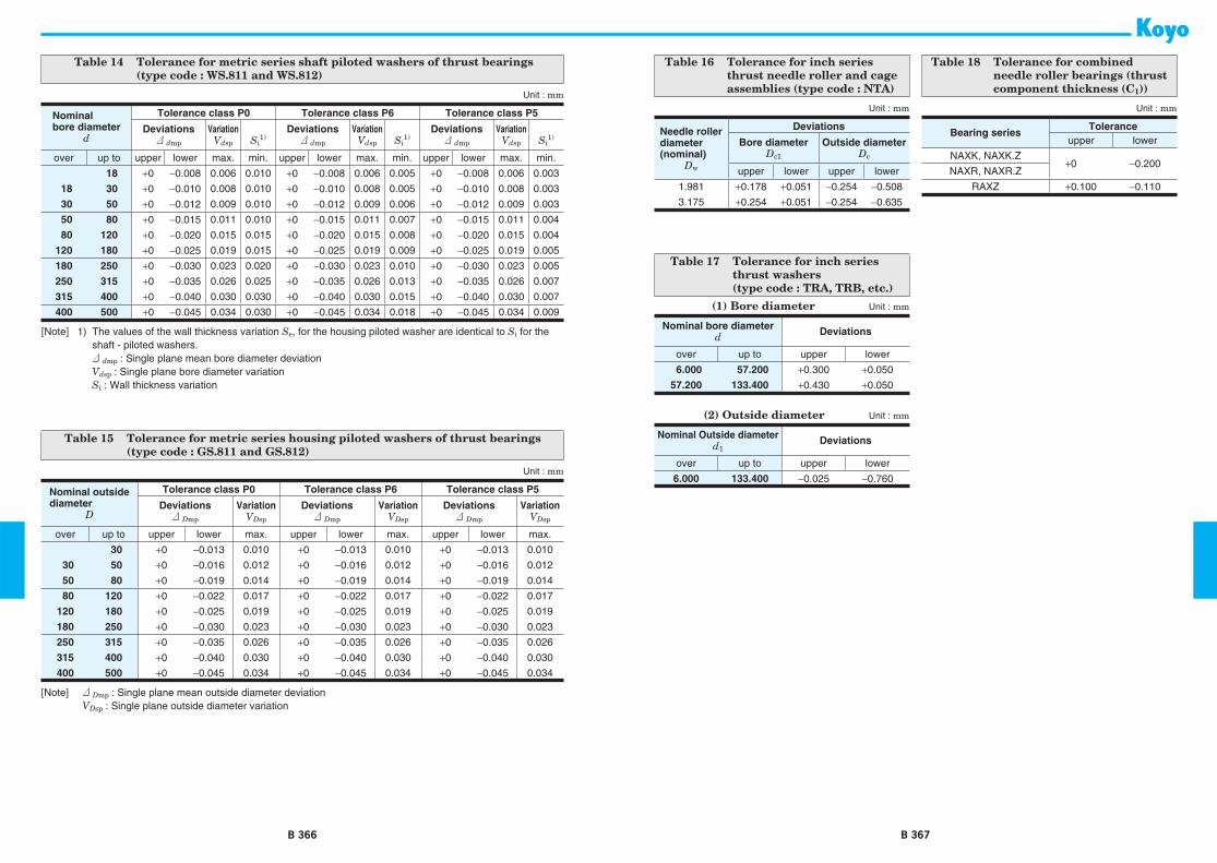
B 366 B 367
Table 14 Tolerance for metric series shaft piloted washers of thrust bearings (type code : WS.811 and WS.812)
Unit : mm
Nominalbore diameter
d
Tolerance class P0 Tolerance class P6 Tolerance class P5
Deviations3 dmp
VariationVdsp Si
1)Deviations3 dmp
VariationVdsp Si
1)Deviations3 dmp
VariationVdsp Si
1)
over up to upper lower max. min. upper lower max. min. upper lower max. min.
18 +0 −0.008 0.006 0.010 +0 −0.008 0.006 0.005 +0 −0.008 0.006 0.003
18 30 +0 −0.010 0.008 0.010 +0 −0.010 0.008 0.005 +0 −0.010 0.008 0.003
30 50 +0 −0.012 0.009 0.010 +0 −0.012 0.009 0.006 +0 −0.012 0.009 0.003
50 80 +0 −0.015 0.011 0.010 +0 −0.015 0.011 0.007 +0 −0.015 0.011 0.004
80 120 +0 −0.020 0.015 0.015 +0 −0.020 0.015 0.008 +0 −0.020 0.015 0.004
120 180 +0 −0.025 0.019 0.015 +0 −0.025 0.019 0.009 +0 −0.025 0.019 0.005
180 250 +0 −0.030 0.023 0.020 +0 −0.030 0.023 0.010 +0 −0.030 0.023 0.005
250 315 +0 −0.035 0.026 0.025 +0 −0.035 0.026 0.013 +0 −0.035 0.026 0.007
315 400 +0 −0.040 0.030 0.030 +0 −0.040 0.030 0.015 +0 −0.040 0.030 0.007
400 500 +0 −0.045 0.034 0.030 +0 −0.045 0.034 0.018 +0 −0.045 0.034 0.009
[Note] 1) The values of the wall thickness variation Se, for the housing piloted washer are identical to Si for the shaft - piloted washers.
3 dmp : Single plane mean bore diameter deviation Vdsp : Single plane bore diameter variation Si : Wall thickness variation
Table 15 Tolerance for metric series housing piloted washers of thrust bearings (type code : GS.811 and GS.812)
Unit : mm
Nominal outside diameter
D
Tolerance class P0 Tolerance class P6 Tolerance class P5
Deviations3 Dmp
VariationVDsp
Deviations3 Dmp
VariationVDsp
Deviations3 Dmp
VariationVDsp
over up to upper lower max. upper lower max. upper lower max.
30 +0 −0.013 0.010 +0 −0.013 0.010 +0 −0.013 0.010
30 50 +0 −0.016 0.012 +0 −0.016 0.012 +0 −0.016 0.012
50 80 +0 −0.019 0.014 +0 −0.019 0.014 +0 −0.019 0.014
80 120 +0 −0.022 0.017 +0 −0.022 0.017 +0 −0.022 0.017
120 180 +0 −0.025 0.019 +0 −0.025 0.019 +0 −0.025 0.019
180 250 +0 −0.030 0.023 +0 −0.030 0.023 +0 −0.030 0.023
250 315 +0 −0.035 0.026 +0 −0.035 0.026 +0 −0.035 0.026
315 400 +0 −0.040 0.030 +0 −0.040 0.030 +0 −0.040 0.030
400 500 +0 −0.045 0.034 +0 −0.045 0.034 +0 −0.045 0.034
[Note] 3 Dmp : Single plane mean outside diameter deviation VDsp : Single plane outside diameter variation
Table 16 Tolerance for inch series thrust needle roller and cage assemblies (type code : NTA)
Unit : mm
Needle roller diameter (nominal)
Dw
Deviations
Bore diameterDc1
Outside diameterDc
upper lower upper lower
1.981 +0.178 +0.051 −0.254 −0.508
3.175 +0.254 +0.051 −0.254 −0.635
Table 17 Tolerance for inch series thrust washers (type code : TRA, TRB, etc.)
(1) Bore diameter Unit : mm
Nominal bore diameterd Deviations
over up to upper lower
6.000 57.200 +0.300 +0.050
57.200 133.400 +0.430 +0.050
(2) Outside diameter Unit : mm
Nominal Outside diameterd1
Deviations
over up to upper lower
6.000 133.400 −0.025 −0.760
Table 18 Tolerance for combined needle roller bearings (thrust component thickness (C1))
Unit : mm
Bearing seriesTolerance
upper lower
NAXK, NAXK.Z+0 −0.200
NAXR, NAXR.Z
RAXZ +0.100 −0.110

B 368 B 369
Table 21 Recommended fit for inch series drawn cup needle roller bearings
Bearing design
Shaft HousingClassification max. min. Classification max. min.
J, JTT 1)
Fw ² 5.556 mm (7/32") 0−0.008 mm(−0.0003")
D ² 7.144 mm (9/32")+0.013 mm(−0.0005")
05.556 mm (7/32") < Fw ² 50.006 mm (1 31/32")
0−0.013 mm(−0.0005")
50.006 mm (1 31/32") < Fw ² 119.856 mm (4 23/32")
0−0.015 mm(−0.0006")
7.144 mm (9/32") < D +0.013 mm(−0.0005")
+0.013 mm(−0.0005")119.856 mm (4 23/32") < Fw
² 180.181 mm (7 3/32") 0
−0.018 mm(−0.0007")
[Note] 1) Special fits When D = 8.733 mm (0.3438") : housing fit : −0.003 mm (−0.0001") maximum, −0.015 mm (−0.0006") minimum When D = 22.212 mm (0.8745") : housing fit : +0.025 mm (+0.0010") maximum, 0 mm (0") minimum When D = 152.400 mm (6.0000") : housing fit : +0.025 mm (+0.0010") maximum, −0.025 mm (−0.0010") minimum
Table 22 Recommended fit for metric series heavy-duty needle roller bearings
Without inner ring
Rotation conditions
Nominal housing bore diameter
D(mm)
ISO tolerance zone for housing
Nominal shaft diameter F shaft
(mm)
ISO tolerance zone for shaft
caged full caged full
Load stationary relative to housingalldiameters
H7 (J7) J6 alldiameters
h6 (h5) h5
General work with larger clearance K7 — g6 —
Load rotates relative to housing N7 M6 f6 g5
[Remark] Care should be taken that the selected bearing internal clearance is appropriate for the operating conditions.
Table 23 Recommended fit for metric series needle roller thrust bearings
Bearing componentsShaft tolerance (shaft piloting)
Housing tolerance (housing piloting)
Needle roller and cage assembly.Types : AXK, FNT
h8 H8
Thin thrust washer.Type : AS
h8 H8
Heavy thrust washer.Type : LS
h8 H8
Shaft-piloted thrust washer.Type : WS.811
h6 (j6) Clearance
Housing-piloted thrust washer.Type : GS.811
Clearance H7 (K7)
Table 24 Recommended fit for metric series cylindrical roller thrust bearings
Bearing componentsShaft tolerance(shaft piloting)
Housing tolerance(housing piloting)
Piloting components
Thrust cylindrical roller and cage assembly.Types : K.811 and K.812
h8 H10 Shaft
Heavy thrust washer.Type : LS
h10 H11 Shaft
Shaft-piloted thrust washer.Types : WS.811, WS.812
h6 (j6) Clearance Shaft
Housing-piloted thrust washer.Types : GS.811, GS.812
Clearance H7 (K7) Housing
[Recommended fit and internal clearance]
Table 19 Recommended fit for metric series radial needle roller and cage assemblies
ConditionTolerance zone class
Shaft Housing boreRadial clearance Fw ² 50 mm Fw > 50 mm
Smaller than normal j 5 h 5
G 6Normal h 5 g 5
Larger than normal g 6 f 6
Table 20 Recommended fit for metric series drawn cup needle roller bearings
Bearing type Operating condition
Shaft fit(recommendedinternal radialclearances)
Housing fit(recommendedinternal radialclearances)
HK, BK(caged)
One piece heavy section steel or cast iron housing
h5 (h6) N6 (N7)
Housing material of low rigidity h5 (h6) R6 (R7)
Outer ring rotation (one piece heavy section steel or cast iron housing)
f5 (f6) R6 (R7)
Oscillating Motion j5 (j6) 1)
[Note] 1) Tolerance dependent on housing design.[Remark] When the bearing is provided with an inner
ring, the shaft tolerance class h5 should be selected.

B 370 B 371
[Shaft and housing specifications]
Table 25 Specifications of shafts and housings (needle roller and cage assemblies, drawn cup needle roller bearings, and heavy-duty needle roller bearings)
Shaft Housing boreRaceway surface Fitting surface Raceway surface Fitting surface
Roundness
· Shaft diameter ² 25 mm : 2.5 μm or less
· Shaft diameter > 25 mm : 2.5 μm × (shaft diameter/25 mm) or less
One-half the shaft diameter tolerance or less
8 μm or one-half the bore tolerance or less
One-half the bore tolerance or less
Variation of mean diameter (Cylindricity)
Within the range of the bearing width, 5 μm or less per 25 mm or one-half the bearing tolerance or less (whichever is smaller)
One-half the shaft diameter tolerance or less
Within the range of the bearing width, 5 μm or less per 25 mm or one-half the bearing tolerance or less (whichever is smaller)
Within the length of the outer ring, 13 μm or one-half the diameter tolerance (whichever is smaller) or less
Surface roughness 0.2 a or less 0.8 a or less 0.2 a or less 1.6 a or less
Hardness 58 HRC or harder 1) — 58 HRC or harder 1) —
Shaft slope 13 μm or less per 25 mm —
[Note] 1) During the carburizing or induction-hardening of case hardened steel, not only must the surface hardness requirement specified above be met, but the case depth of HV 550 (52.3 HRC) must be met in the range of 0.08 Dw to 0.10 Dw mm. (Dw : roller diameter)
Table 26 Needle roller thrust bearing mounting surface specifications
Flatness(dishing or coning)
Maximum angle : Arctan 0.001
Squareness Maximum angle : Arctan 0.0005
Roughness (Ra) 0.2 a or less
Hardness58 HRC or harder (refer to the note for Table 25 above regarding depth.)

B 372
u Fw u Fw u Ew
Bc Bc
K K ZW
Radial needle roller and cage assembliessingle-row, double-row assembliesmetric seriesK, K ZW series
B 373
u S u H
raceway surfaces to be58 HRC or equivalent
Boundary dimensions
Bearing No.
Basic load ratings Fatigue Cage
material 1)
P / S
Limiting speeds(Refer.)Mass(kg)
Recommended dimensions(mm) (kN) load limit (min−1) (mm)
Shaft dia.
Fw Ew
BcCr C0r
(kN) Grease lub.
Oil lub.S (Shaft) H (Housing)
−0.20−0.55 Cu max. min. max. min.
3 3 5 7 K3X5X7TN 1.56 1.29 0.200 P 48 000 74 000 0.0002 3.000 2.996 5.004 5.012
4 4 7 7 K4X7X7TN 1.83 1.32 0.200 P 34 000 52 000 0.0005 4.000 3.995 7.014 7.005
5 5 8 8 K5X8X8TN 2.18 1.71 0.260 P 31 000 47 000 0.0007 5.000 4.995 8.014 8.0055 8 10 K5X8X10TN 3.04 2.63 0.400 P 31 000 47 000 0.0008 5.000 4.995 8.014 8.0055 9 13 K5X9X13TN 4.29 3.55 0.540 P 26 000 40 000 0.002 5.000 4.995 9.014 9.005
6 6 9 8 K6X9X8H 3.19 2.90 0.420 S 29 000 44 000 0.0008 6.000 5.995 9.014 9.0056 9 8 K6X9X8TN 2.47 2.07 0.310 P 29 000 44 000 0.001 6.000 5.995 9.014 9.0056 9 10 K6X9X10TN 3.07 2.74 0.420 P 29 000 44 000 0.001 6.000 5.995 9.014 9.005
7 7 10 8 K7X10X8TN 2.74 2.44 0.370 P 28 000 42 000 0.001 7.000 6.994 10.014 10.0057 10 10 K7X10X10TN 3.40 3.22 0.490 P 28 000 42 000 0.001 7.000 6.994 10.014 10.0057 11 15 K7X11X15TN 6.44 6.24 0.940 P 23 000 35 000 0.003 7.000 6.994 11.017 11.006
8 8 11 8 K8X11X8FV 3.23 3.11 0.470 S 26 000 41 000 0.002 8.000 7.994 11.017 11.0068 11 8 K8X11X8TN 2.34 2.05 0.300 P 26 000 41 000 0.001 8.000 7.994 11.017 11.0068 11 10 K8X11X10H 4.57 4.89 0.740 S 26 000 41 000 0.002 8.000 7.994 11.017 11.006
8 11 10 K8X11X10FV 4.01 4.11 0.630 S 26 000 41 000 0.002 8.000 7.994 11.017 11.0068 11 10 K8x11x10TN 3.84 3.91 0.600 P 26 000 41 000 0.001 8.000 7.994 11.006 11.0178 11 13 K8x11x13TN 5.18 5.75 0.870 P 26 000 41 000 0.002 8.000 7.994 11.006 11.017
8 11 13 K8X11X13H 5.22 5.78 0.880 S 26 000 41 000 0.003 8.000 7.994 11.017 11.006
9 9 12 10 K9X12X10FH 4.27 4.60 0.700 S 26 000 40 000 0.003 9.000 8.994 12.017 12.0069 12 10 K9X12X10FV 4.27 4.60 0.700 S 26 000 40 000 0.002 9.000 8.994 12.017 12.0069 12 13 K9X12X13FH 5.57 6.47 0.980 S 26 000 40 000 0.003 9.000 8.994 12.017 12.006
9 12 13 K9X12X13FV 5.57 6.47 0.980 S 26 000 40 000 0.003 9.000 8.994 12.017 12.0069 13 8 K9X13X8H 3.96 3.50 0.530 S 21 000 32 000 0.003 9.000 8.994 13.017 13.006
10 10 13 10 K10X13X10H 5.40 6.43 0.980 S 25 000 39 000 0.002 10.000 9.994 13.017 13.00610 13 10 K10X13X10TN 4.29 4.77 0.730 P 25 000 39 000 0.002 10.000 9.994 13.017 13.00610 13 13 K10X13X13 5.90 7.16 1.10 S 25 000 39 000 0.003 10.000 9.994 13.017 13.006
[Note] 1) Cage material: P: polymer cage, S: steel cage
Shaft dia. 3 ∼ (10) mm

B 374
u Fw u Fw u Ew
Bc Bc
K K ZW
Radial needle roller and cage assembliessingle-row, double-row assembliesmetric seriesK, K ZW series
B 375
u S u H
raceway surfaces to be58 HRC or equivalent
Boundary dimensions
Bearing No.
Basic load ratings Fatigue Cage
material 1)
P / S
Limiting speeds(Refer.)Mass(kg)
Recommended dimensions(mm) (kN) load limit (min−1) (mm)
Shaft dia.
Fw Ew
BcCr C0r
(kN) Grease lub.
Oil lub.S (Shaft) H (Housing)
−0.20−0.55 Cu max. min. max. min.
10 10 13 16 K10X13X16 7.43 9.64 1.50 S 25 000 39 000 0.004 10.000 9.994 13.017 13.00610 14 10 K10X14X10H 6.12 6.29 0.960 S 20 000 31 000 0.003 10.000 9.994 14.017 14.00610 14 13 K10X14X13H 7.88 8.71 1.35 S 20 000 31 000 0.004 10.000 9.994 14.017 14.006
10 16 12 K10X16X12F 8.39 7.47 1.15 S 15 000 24 000 0.006 10.000 9.994 16.017 16.00610 16 12 K10X16X12TN 7.50 6.40 0.970 P 15 000 24 000 0.005 10.000 9.994 16.017 16.006
12 12 15 10 K12X15X10H 5.85 7.51 1.15 S 24 000 37 000 0.003 12.000 11.992 15.017 15.00612 15 13 K12X15X13H 6.78 9.03 1.40 S 24 000 37 000 0.004 12.000 11.992 15.017 15.00612 16 13 K12X16X13H 7.49 8.51 1.60 S 19 000 30 000 0.006 12.000 11.992 16.017 16.006
12 17 13 K12X17X13 8.93 9.29 1.20 S 16 000 25 000 0.008 12.000 11.992 17.017 17.00612 18 12 K12X18X12H 9.76 9.40 1.40 S 14 000 22 000 0.009 12.000 11.992 18.017 18.006
13 13 17 10 K13X17X10 7.22 8.33 1.25 S 19 000 29 000 0.004 13.000 12.992 17.017 17.00613 18 15 K13X18X15F 10.8 12.1 1.85 S 16 000 25 000 0.008 13.000 12.992 18.017 18.006
14 14 18 8 K14X18X8 5.39 5.82 0.880 S 19 000 29 000 0.004 14.000 13.992 18.017 18.00614 18 10 K14X18X10 7.17 8.41 1.30 S 19 000 29 000 0.005 14.000 13.992 18.017 18.00614 18 13 K14X18X13 9.73 12.5 1.90 S 19 000 29 000 0.006 14.000 13.992 18.017 18.006
14 18 15 K14X18X15 10.5 13.8 2.15 S 19 000 29 000 0.007 14.000 13.992 18.017 18.00614 18 17 K14X18X17H 12.4 17.1 2.65 S 19 000 29 000 0.008 14.000 13.992 18.017 18.00614 19 13 K14X19X13H 10.2 11.4 1.75 S 16 000 24 000 0.008 14.000 13.992 19.020 19.007
14 19 18 K14X19X18F 13.2 16.0 2.50 S 16 000 24 000 0.011 14.000 13.992 19.020 19.00714 20 12 K14X20X12 10.5 10.6 1.60 S 14 000 21 000 0.009 14.000 13.992 20.020 20.007
15 15 18 14 K15X18X14TN 7.92 11.9 1.80 P 13 000 23 000 0.003 15.000 14.992 18.017 18.00615 18 16 K15X18X16F 8.36 12.6 1.95 S 13 000 23 000 0.005 15.000 14.992 18.017 18.00615 18 17 K15X18X17 8.08 12.1 1.85 S 23 000 36 000 0.005 15.000 14.992 18.017 18.006
15 19 10 K15X19X10 7.87 9.69 1.45 S 18 000 28 000 0.005 15.000 14.992 19.020 19.00715 19 13 K15X19X13 9.66 12.6 1.90 S 18 000 28 000 0.007 15.000 14.992 19.020 19.00715 19 17 K15X19X17H 12.3 17.2 2.65 S 18 000 28 000 0.009 15.000 14.992 19.020 19.007
15 19 22 K15X19X22ZW 12.2 17.0 2.60 S 18 000 28 000 0.010 15.000 14.992 19.020 19.007
[Note] 1) Cage material: P: polymer cage, S: steel cage
Shaft dia. (10) ∼ (15) mm

B 376
u Fw u Fw u Ew
Bc Bc
K K ZW
Radial needle roller and cage assembliessingle-row, double-row assembliesmetric seriesK, K ZW series
B 377
u S u H
raceway surfaces to be58 HRC or equivalent
Boundary dimensions
Bearing No.
Basic load ratings Fatigue Cage
material 1)
P / S
Limiting speeds(Refer.)Mass(kg)
Recommended dimensions(mm) (kN) load limit (min−1) (mm)
Shaft dia.
Fw Ew
BcCr C0r
(kN) Grease lub.
Oil lub.S (Shaft) H (Housing)
−0.20−0.55 Cu max. min. max. min.
15 15 20 13 K15X20X13H 9.93 11.3 1.80 S 16 000 24 000 0.008 15.000 14.992 20.020 20.00715 21 15 K15X21X15 13.4 14.8 2.30 S 14 000 21 000 0.013 15.000 14.992 21.020 21.00715 21 21 K15X21X21H 18.0 21.7 3.40 S 14 000 21 000 0.018 15.000 14.992 21.020 21.007
16 16 20 8 K16X20X8F 6.37 7.51 1.15 S 18 000 28 000 0.005 16.000 15.992 20.020 20.00716 20 10 K16X20X10H 7.82 9.76 1.50 S 18 000 28 000 0.006 16.000 15.992 20.020 20.00716 20 13 K16X20X13 10.1 13.5 2.05 S 18 000 28 000 0.007 16.000 15.992 20.020 20.007
16 20 14 K16X20X14 10.8 14.8 2.25 S 18 000 28 000 0.007 16.000 15.992 20.020 20.00716 20 17 K16X20X17H 12.9 18.5 2.85 S 18 000 28 000 0.008 16.000 15.992 20.020 20.00716 20 20 K16X20X20 13.4 19.5 3.05 S 18 000 28 000 0.011 16.000 15.992 20.020 20.007
16 22 12 K16X22X12 11.2 11.9 1.80 S 19 000 29 000 0.010 16.000 15.992 22.020 22.00716 22 16 K16X22X16H 14.9 17.2 2.70 S 19 000 29 000 0.014 16.000 15.992 22.020 22.00716 22 20 K16X22X20 18.6 22.9 3.60 S 19 000 29 000 0.017 16.000 15.992 22.020 22.007
16 24 20 K16X24X20 20.2 21.4 3.45 S 20 000 30 000 0.025 16.000 15.992 24.020 24.007
17 17 20 10 K17X20X10 5.96 8.53 1.30 S 16 000 25 000 0.004 17.000 16.992 20.020 20.00717 21 10 K17X21X10 8.12 10.4 1.60 S 17 000 26 000 0.006 17.000 16.992 21.020 21.00717 21 12.8 K17X21X13H 10.5 14.5 2.20 S 17 000 26 000 0.008 17.000 16.992 21.020 21.007
17 21 15 K17X21X15 11.4 16.1 2.50 S 17 000 26 000 0.008 17.000 16.992 21.020 21.00717 21 17 K17X21X17H 13.4 19.8 3.05 S 17 000 26 000 0.011 17.000 16.992 21.020 21.00717 22 20 K17X22X20FH 17.0 23.3 3.65 S 17 000 27 000 0.015 17.000 16.992 22.020 22.007
17 23 15 K17X23X15F 14.1 16.3 2.55 S 18 000 27 000 0.010 17.000 16.992 23.020 23.007
18 18 22 8 K18X22X8F 6.32 7.70 1.15 S 16 000 24 000 0.005 18.000 17.992 22.020 22.00718 22 10 K18X22X10H 8.41 11.1 1.70 S 16 000 24 000 0.006 18.000 17.992 22.020 22.00718 22 13 K18X22X13H 10.8 15.4 2.35 S 16 000 24 000 0.008 18.000 17.992 22.020 22.007
18 22 14 K18X22X14 11.6 16.8 2.55 S 16 000 24 000 0.009 18.000 17.992 22.020 22.00718 22 14 K18X22X14FV 11.3 16.3 2.45 S 16 000 24 000 0.009 18.000 17.992 22.020 22.00718 22 17 K18X22X17H 13.3 19.9 3.10 S 16 000 24 000 0.009 18.000 17.992 22.020 22.007
18 22 20 K18X22X20F 15.0 23.4 3.65 S 16 000 24 000 0.011 18.000 17.992 22.020 22.00718 24 12 K18X24X12 11.8 13.1 1.95 S 17 000 25 000 0.011 18.000 17.992 24.020 24.007
[Note] 1) Cage material: P: polymer cage, S: steel cage
Shaft dia. (15) ∼ (18) mm

B 378
u Fw u Fw u Ew
Bc Bc
K K ZW
Radial needle roller and cage assembliessingle-row, double-row assembliesmetric seriesK, K ZW series
B 379
u S u H
raceway surfaces to be58 HRC or equivalent
Boundary dimensions
Bearing No.
Basic load ratings Fatigue Cage
material 1)
P / S
Limiting speeds(Refer.)Mass(kg)
Recommended dimensions(mm) (kN) load limit (min−1) (mm)
Shaft dia.
Fw Ew
BcCr C0r
(kN) Grease lub.
Oil lub.S (Shaft) H (Housing)
−0.20−0.55 Cu max. min. max. min.
18 18 24 20 K18X24X20H 19.4 24.9 3.90 S 16 000 25 000 0.019 18.000 17.992 24.020 24.00718 25 22 K18X25X22H 23.3 28.6 4.50 S 17 000 26 000 0.025 18.000 17.992 25.020 25.00718 26 12 K18X26X12FV 13.8 13.5 2.10 S 11 000 17 000 0.020 18.000 17.992 26.020 26.007
18 26 20 K18X26X20F 21.7 24.1 3.85 S 17 000 26 000 0.027 18.000 17.992 26.020 26.007
19 19 23 13 K19X23X13 10.8 15.5 2.35 S 15 000 23 000 0.008 19.000 18.991 23.020 23.00719 23 17 K19X23X17 13.4 20.6 3.20 S 15 000 23 000 0.011 19.000 18.991 23.020 23.007
20 20 24 8 K20X24X8F 7.31 9.60 1.50 S 14 000 22 000 0.005 20.000 19.991 24.020 24.00720 24 10 K20X24X10H 8.97 12.5 2.05 S 14 000 22 000 0.006 20.000 19.991 24.020 24.00720 24 12 K20X24X12 10.7 15.7 2.40 S 14 000 22 000 0.008 20.000 19.991 24.020 24.007
20 24 13 K20X24X13H 11.5 17.3 1.30 S 14 000 22 000 0.009 20.000 19.991 24.020 24.00720 24 14 K20X24X14 12.4 18.9 2.85 S 14 000 22 000 0.009 20.000 19.991 24.020 24.00720 24 17 K20X24X17H 14.8 23.7 3.65 S 14 000 22 000 0.011 20.000 19.991 24.020 24.007
20 26 12 K20X26X12 13.0 15.3 2.30 S 15 000 23 000 0.012 20.000 19.991 26.020 26.00720 26 13 K20X26X13H 13.4 15.9 2.35 S 15 000 23 000 0.014 20.000 19.991 26.020 26.00720 26 17 K20X26X17H 19.3 25.5 4.00 S 15 000 23 000 0.017 20.000 19.991 26.020 26.007
20 26 20 K20X26X20 20.3 27.2 4.25 S 15 000 23 000 0.020 20.000 19.991 26.020 26.00720 28 20 K20X28X20H 24.6 29.0 2.70 S 15 000 23 000 0.028 20.000 19.991 28.020 28.00720 28 25 K20X28X25H 29.7 37.0 5.80 S 15 000 23 000 0.036 20.000 19.991 28.020 28.007
20 30 30 K20X30X30H 38.9 45.8 7.20 S 16 000 24 000 0.055 20.000 19.991 30.020 30.00720 32 36 K20X32X36H 49.9 57.0 9.15 S 16 000 25 000 0.082 20.000 19.991 32.025 32.009
21 21 25 17 K21X25X17H 14.3 23.1 3.60 S 14 000 21 000 0.013 21.000 20.991 25.020 25.007
22 22 26 10 K22X26X10H 9.81 14.5 2.20 S 13 000 20 000 0.007 22.000 21.991 26.020 26.00722 26 13 K22X26X13H 11.8 18.3 2.95 S 13 000 20 000 0.012 22.000 21.991 26.020 26.00722 26 17 K22X26X17H 15.6 26.3 4.05 S 13 000 20 000 0.012 22.000 21.991 26.020 26.007
22 26 18 K22X26X18H 15.3 25.5 4.00 S 13 000 20 000 0.017 22.000 21.991 26.020 26.00722 28 13 K22X28X13 13.9 17.1 2.60 S 13 000 20 000 0.015 22.000 21.991 28.020 28.00722 28 17 K22X28X17H 18.2 24.2 3.80 S 13 000 20 000 0.020 22.000 21.991 28.020 28.007
[Note] 1) Cage material: P: polymer cage, S: steel cage
Shaft dia. (18) ∼ (22) mm
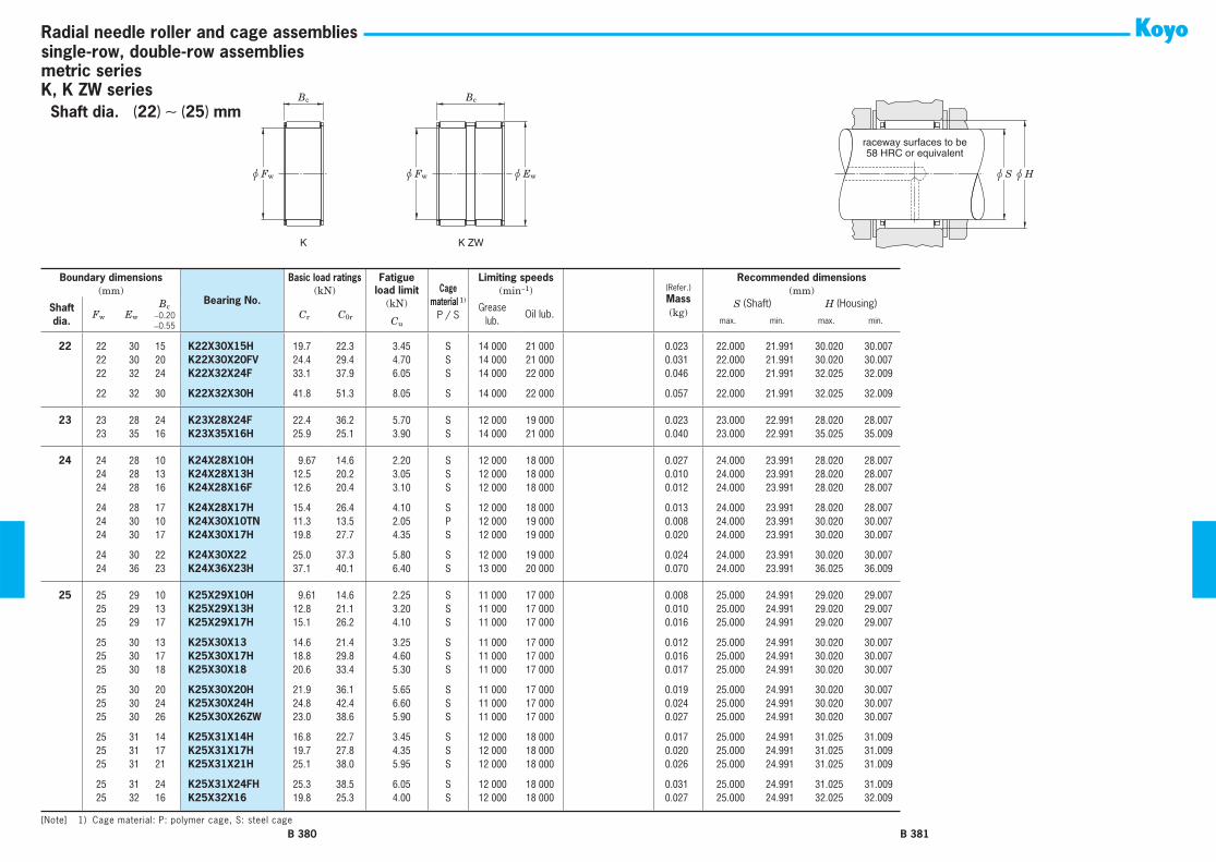
B 380
u Fw u Fw u Ew
Bc Bc
K K ZW
Radial needle roller and cage assembliessingle-row, double-row assembliesmetric seriesK, K ZW series
B 381
u S u H
raceway surfaces to be58 HRC or equivalent
Boundary dimensions
Bearing No.
Basic load ratings Fatigue Cage
material 1)
P / S
Limiting speeds(Refer.)Mass(kg)
Recommended dimensions(mm) (kN) load limit (min−1) (mm)
Shaft dia.
Fw Ew
BcCr C0r
(kN) Grease lub.
Oil lub.S (Shaft) H (Housing)
−0.20−0.55 Cu max. min. max. min.
22 22 30 15 K22X30X15H 19.7 22.3 3.45 S 14 000 21 000 0.023 22.000 21.991 30.020 30.00722 30 20 K22X30X20FV 24.4 29.4 4.70 S 14 000 21 000 0.031 22.000 21.991 30.020 30.00722 32 24 K22X32X24F 33.1 37.9 6.05 S 14 000 22 000 0.046 22.000 21.991 32.025 32.009
22 32 30 K22X32X30H 41.8 51.3 8.05 S 14 000 22 000 0.057 22.000 21.991 32.025 32.009
23 23 28 24 K23X28X24F 22.4 36.2 5.70 S 12 000 19 000 0.023 23.000 22.991 28.020 28.00723 35 16 K23X35X16H 25.9 25.1 3.90 S 14 000 21 000 0.040 23.000 22.991 35.025 35.009
24 24 28 10 K24X28X10H 9.67 14.6 2.20 S 12 000 18 000 0.027 24.000 23.991 28.020 28.00724 28 13 K24X28X13H 12.5 20.2 3.05 S 12 000 18 000 0.010 24.000 23.991 28.020 28.00724 28 16 K24X28X16F 12.6 20.4 3.10 S 12 000 18 000 0.012 24.000 23.991 28.020 28.007
24 28 17 K24X28X17H 15.4 26.4 4.10 S 12 000 18 000 0.013 24.000 23.991 28.020 28.00724 30 10 K24X30X10TN 11.3 13.5 2.05 P 12 000 19 000 0.008 24.000 23.991 30.020 30.00724 30 17 K24X30X17H 19.8 27.7 4.35 S 12 000 19 000 0.020 24.000 23.991 30.020 30.007
24 30 22 K24X30X22 25.0 37.3 5.80 S 12 000 19 000 0.024 24.000 23.991 30.020 30.00724 36 23 K24X36X23H 37.1 40.1 6.40 S 13 000 20 000 0.070 24.000 23.991 36.025 36.009
25 25 29 10 K25X29X10H 9.61 14.6 2.25 S 11 000 17 000 0.008 25.000 24.991 29.020 29.00725 29 13 K25X29X13H 12.8 21.1 3.20 S 11 000 17 000 0.010 25.000 24.991 29.020 29.00725 29 17 K25X29X17H 15.1 26.2 4.10 S 11 000 17 000 0.016 25.000 24.991 29.020 29.007
25 30 13 K25X30X13 14.6 21.4 3.25 S 11 000 17 000 0.012 25.000 24.991 30.020 30.00725 30 17 K25X30X17H 18.8 29.8 4.60 S 11 000 17 000 0.016 25.000 24.991 30.020 30.00725 30 18 K25X30X18 20.6 33.4 5.30 S 11 000 17 000 0.017 25.000 24.991 30.020 30.007
25 30 20 K25X30X20H 21.9 36.1 5.65 S 11 000 17 000 0.019 25.000 24.991 30.020 30.00725 30 24 K25X30X24H 24.8 42.4 6.60 S 11 000 17 000 0.024 25.000 24.991 30.020 30.00725 30 26 K25X30X26ZW 23.0 38.6 5.90 S 11 000 17 000 0.027 25.000 24.991 30.020 30.007
25 31 14 K25X31X14H 16.8 22.7 3.45 S 12 000 18 000 0.017 25.000 24.991 31.025 31.00925 31 17 K25X31X17H 19.7 27.8 4.35 S 12 000 18 000 0.020 25.000 24.991 31.025 31.00925 31 21 K25X31X21H 25.1 38.0 5.95 S 12 000 18 000 0.026 25.000 24.991 31.025 31.009
25 31 24 K25X31X24FH 25.3 38.5 6.05 S 12 000 18 000 0.031 25.000 24.991 31.025 31.00925 32 16 K25X32X16 19.8 25.3 4.00 S 12 000 18 000 0.027 25.000 24.991 32.025 32.009
[Note] 1) Cage material: P: polymer cage, S: steel cage
Shaft dia. (22) ∼ (25) mm

B 382
u Fw u Fw u Ew
Bc Bc
K K ZW
Radial needle roller and cage assembliessingle-row, double-row assembliesmetric seriesK, K ZW series
B 383
u S u H
raceway surfaces to be58 HRC or equivalent
Boundary dimensions
Bearing No.
Basic load ratings Fatigue Cage
material 1)
P / S
Limiting speeds(Refer.)Mass(kg)
Recommended dimensions(mm) (kN) load limit (min−1) (mm)
Shaft dia.
Fw Ew
BcCr C0r
(kN) Grease lub.
Oil lub.S (Shaft) H (Housing)
−0.20−0.55 Cu max. min. max. min.
25 25 33 20 K25X33X20H 28.8 37.6 5.95 S 12 000 18 000 0.035 25.000 24.991 33.025 33.00925 33 24 K25X33X24H 32.3 43.5 6.85 S 12 000 18 000 0.038 25.000 24.991 33.025 33.00925 33 25 K25X33X25H 33.0 44.6 7.00 S 12 000 18 000 0.041 25.000 24.991 33.025 33.009
25 35 23.7 K25X35X23,7H 35.9 42.3 6.90 S 12 000 19 000 0.050 25.000 24.991 35.025 35.00925 35 25 K25X35X25H 37.8 46.2 7.25 S 12 000 19 000 0.054 25.000 24.991 35.025 35.00925 35 30 K25X35X30H 44.6 57.2 9.00 S 12 000 19 000 0.060 25.000 24.991 35.025 35.009
25 35 36 K25X35X36H 52.4 70.4 11.0 S 12 000 19 000 0.074 25.000 24.991 35.025 35.00925 37 20 K25X37X20H 32.5 34.1 5.45 S 12 000 19 000 0.055 25.000 24.991 37.025 37.009
26 26 30 10 K26X30X10F 9.46 14.5 2.20 S 11 000 16 000 0.007 26.000 25.991 30.020 30.00726 30 13 K26X30X13 12.3 20.4 3.10 S 10 000 16 000 0.011 26.000 25.991 30.020 30.00726 30 17 K26X30X17 15.0 26.3 3.10 S 10 000 16 000 0.014 26.000 25.991 30.020 30.007
26 30 22 K26X30X22ZW 16.7 30.2 4.60 S 10 000 16 000 0.018 26.000 25.991 30.020 30.007
28 28 32 21 K28X32X21F 18.7 35.7 5.55 S 9 900 15 000 0.018 28.000 27.991 32.025 32.00928 33 13 K28X33X13F 14.1 21.4 3.25 S 10 000 15 000 0.015 28.000 27.991 33.025 33.00928 33 17 K28X33X17H 19.8 33.0 5.10 S 10 000 15 000 0.018 28.000 27.991 33.025 33.009
28 33 27 K28X33X27 29.0 53.8 8.30 S 10 000 15 000 0.027 28.000 27.991 33.025 33.00928 34 17 K28X34X17 21.1 31.5 6.30 S 10 000 16 000 0.022 28.000 27.991 34.025 34.00928 34 20 K28X34X20H 24.4 37.8 7.65 S 10 000 16 000 0.025 28.000 27.991 34.025 34.009
28 35 15 K28X35X15H 19.5 25.6 3.95 S 10 000 16 000 0.025 28.000 27.991 35.025 35.00928 35 16 K28X35X16H 21.5 29.1 4.60 S 10 000 16 000 0.026 28.000 27.991 35.025 35.00928 35 27 K28X35X27H 35.2 54.7 8.50 S 10 000 16 000 0.042 28.000 27.991 35.025 35.009
28 36 20 K28X36X20FV 27.8 37.0 5.95 S 10 000 16 000 0.039 28.000 27.991 36.025 36.00928 38 25 K28X38X25,5 40.9 52.7 8.25 S 11 000 16 000 0.059 28.000 27.991 38.025 38.00928 40 18 K28X40X18H 33.6 36.5 5.90 S 11 000 17 000 0.060 28.000 27.991 40.025 40.009
28 40 25 K28X40X25H 45.5 54.0 8.55 S 11 000 17 000 0.072 28.000 27.991 40.025 40.00928 40 30 K28X40X30H 54.3 67.8 10.7 S 11 000 17 000 0.100 28.000 27.991 40.025 40.00928 41 25 K28X41X25H 49.2 57.1 9.05 S 11 000 17 000 0.082 28.000 27.991 41.025 41.009
29 29 34 27 K29X34X27F 28.9 54.0 8.40 S 9 700 15 000 0.033 29.000 28.991 34.025 34.009
[Note] 1) Cage material: P: polymer cage, S: steel cage
Shaft dia. (25) ∼ 29 mm

B 384
u Fw u Fw u Ew
Bc Bc
K K ZW
Radial needle roller and cage assembliessingle-row, double-row assembliesmetric seriesK, K ZW series
B 385
u S u H
raceway surfaces to be58 HRC or equivalent
Boundary dimensions
Bearing No.
Basic load ratings Fatigue Cage
material 1)
P / S
Limiting speeds(Refer.)Mass(kg)
Recommended dimensions(mm) (kN) load limit (min−1) (mm)
Shaft dia.
Fw Ew
BcCr C0r
(kN) Grease lub.
Oil lub.S (Shaft) H (Housing)
−0.20−0.55 Cu max. min. max. min.
30 30 34 13 K30X34X13 13.5 24.1 3.65 S 9 200 14 000 0.011 30.000 29.991 34.025 34.00930 35 13 K30X35X13H 15.6 24.9 3.80 S 9 300 14 000 0.017 30.000 29.991 35.025 35.00930 35 17 K30X35X17H 20.2 34.6 5.35 S 9 300 14 000 0.022 30.000 29.991 35.025 35.009
30 35 20 K30X35X20H 23.5 41.9 6.55 S 9 300 14 000 0.023 30.000 29.991 35.025 35.00930 35 22.8 K30X35X23F 25.6 46.8 7.40 S 9 300 14 000 0.028 30.000 29.991 35.025 35.00930 35 27 K30X35X27H 30.6 59.0 9.10 S 9 300 14 000 0.032 30.000 29.991 35.025 35.009
30 35 27 K30X35X27HZW 19.9 33.6 5.10 S 9 300 14 000 0.033 30.000 29.991 35.025 35.00930 36 14 K30X36X14 18.0 26.2 4.00 S 9 500 15 000 0.020 30.000 29.991 36.025 36.00930 37 17.8 K30X37X18 24.3 34.8 6.00 S 9 600 15 000 0.033 30.000 29.991 37.025 37.009
30 40 30 K30X40X30H 49.2 67.8 10.6 S 9 900 15 000 0.077 30.000 29.991 40.025 40.00930 42 30 K30X42X30H 54.2 68.6 10.8 S 10 000 16 000 0.096 30.000 29.991 42.025 42.00930 44 26 K30X44X26H 52.4 59.9 9.55 S 10 000 16 000 0.095 30.000 29.991 44.025 44.009
32 32 36 15 K32X36X15F 11.6 20.2 3.10 S 8 600 13 000 0.015 32.000 31.989 36.025 36.00932 37 13 K32X37X13 15.2 24.4 4.00 S 8 700 13 000 0.018 32.000 31.989 37.025 37.00932 37 17 K32X37X17H 20.0 34.8 5.40 S 8 700 13 000 0.020 32.000 31.989 37.025 37.009
32 37 27 K32X37X27 29.3 56.8 8.85 S 8 700 13 000 0.035 32.000 31.989 37.025 37.00932 38 20 K32X38X20H 27.3 45.7 7.15 S 8 800 14 000 0.030 32.000 31.989 38.025 38.00932 38 26 K32X38X26H 33.2 58.8 9.15 S 8 800 14 000 0.037 32.000 31.989 38.025 38.009
32 39 16 K32X39X16H 23.0 33.0 5.20 S 8 900 14 000 0.030 32.000 31.989 39.025 39.00932 39 18 K32X39X18H 25.8 38.2 6.05 S 8 900 14 000 0.033 32.000 31.989 39.025 39.00932 40 25 K32X40X25H 37.9 57.2 8.90 S 9 000 14 000 0.052 32.000 31.989 40.025 40.009
32 40 36 K32X40X36H 52.3 86.4 13.6 S 9 000 14 000 0.080 32.000 31.989 40.025 40.00932 42 42 K32X42X42H 69.2 108 17.1 S 9 200 14 000 0.110 32.000 31.989 42.025 42.00932 46 18 K32X46X18H 39.2 41.9 6.80 S 9 600 15 000 0.075 32.000 31.989 46.025 46.009
32 46 32 K32X46X32H 67.0 83.4 13.1 S 9 600 15 000 0.140 32.000 31.989 46.025 46.00932 46 40 K32X46X40H 81.7 108 12.2 S 9 600 15 000 0.158 32.000 31.989 46.025 46.009
33 33 51 23 K33X51X23H 55.9 57.6 9.35 S 9 600 15 000 0.140 33.000 32.989 51.029 51.010
34 34 38 11 K34X38X11 12.2 21.9 3.35 S 8 100 12 000 0.011 34.000 33.989 38.025 38.009
[Note] 1) Cage material: P: polymer cage, S: steel cage
Shaft dia. 30 ∼ (34) mm

B 386
u Fw u Fw u Ew
Bc Bc
K K ZW
Radial needle roller and cage assembliessingle-row, double-row assembliesmetric seriesK, K ZW series
B 387
u S u H
raceway surfaces to be58 HRC or equivalent
Boundary dimensions
Bearing No.
Basic load ratings Fatigue Cage
material 1)
P / S
Limiting speeds(Refer.)Mass(kg)
Recommended dimensions(mm) (kN) load limit (min−1) (mm)
Shaft dia.
Fw Ew
BcCr C0r
(kN) Grease lub.
Oil lub.S (Shaft) H (Housing)
−0.20−0.55 Cu max. min. max. min.
34 34 44 26 K34X44X26FH 42.9 58.9 9.40 S 8 600 13 000 0.080 34.000 33.989 44.025 44.009
35 35 40 13 K35X40X13H 16.2 27.2 4.15 S 7 900 12 000 0.018 35.000 34.989 40.025 40.00935 40 17 K35X40X17H 22.1 40.8 6.35 S 7 900 12 000 0.025 35.000 34.989 40.025 40.00935 40 19 K35X40X19H 23.2 43.2 6.80 S 7 900 12 000 0.025 35.000 34.989 40.025 40.009
35 40 25 K35X40X25H 28.4 56.2 8.70 S 7 900 12 000 0.035 35.000 34.989 40.025 40.00935 40 27 K35X40X27H 29.8 59.6 9.20 S 7 900 12 000 0.037 35.000 34.989 40.025 40.00935 42 16 K35X42X16AH 24.5 36.8 5.80 S 8 100 12 000 0.031 35.000 34.989 42.025 42.009
35 42 18 K35X42X18 27.5 42.6 6.75 S 8 100 12 000 0.035 35.000 34.989 42.025 42.00935 42 20 K35X42X20H 30.4 48.5 7.65 S 8 100 12 000 0.037 35.000 34.989 42.025 42.00935 42 30 K35X42X30FH 40.5 70.0 10.9 S 8 100 12 000 0.061 35.000 34.989 42.025 42.009
35 45 20 K35X45X20FH 36.5 49.9 8.00 S 8 400 13 000 0.059 35.000 34.989 45.025 45.00935 45 30 K35X45X30F 51.2 74.5 11.7 S 8 400 13 000 0.100 35.000 34.989 45.025 45.00935 45 35 K35X45X35H 62.1 95.5 15.0 S 8 400 13 000 0.085 35.000 34.989 45.025 45.009
35 45 41 K35X45X41 70.8 113 17.7 S 8 400 13 000 0.120 35.000 34.989 45.025 45.00935 45 49 K35X45X49H 82.5 138 21.4 S 8 400 13 000 0.143 35.000 34.989 45.025 45.00935 45 49 K35X45X49HZW 71.8 115 18.1 S 8 400 13 000 0.143 35.000 34.989 45.025 45.009
35 50 23 K35X50X23H 53.0 60.3 9.75 S 8 700 13 000 0.110 35.000 34.989 50.025 50.00935 50 40 K35X50X40F 79.7 102 16.2 S 8 700 13 000 0.200 35.000 34.989 50.025 50.009
36 36 40 29 K36X40X29TN 21.2 45.2 7.15 P 7 600 12 000 0.029 36.000 35.989 40.025 40.00936 42 16 K36X42X16 22.8 37.7 5.95 S 7 800 12 000 0.027 36.000 35.989 42.025 42.009
37 37 42 13 K37X42X13H 16.9 29.4 4.50 S 7 500 11 000 0.017 37.000 36.989 42.025 42.00937 42 17 K37X42X17H 21.9 41.0 6.35 S 7 500 11 000 0.025 37.000 36.989 42.025 42.00937 42 27 K37X42X27F 32.1 66.9 10.4 S 7 500 11 000 0.039 37.000 36.989 42.025 42.009
37 44 19 K37X44X19H 29.7 48.0 7.65 S 7 600 12 000 0.039 37.000 36.989 44.025 44.009
38 38 41 9 K38X41X9TN 5.93 11.0 1.65 P 7 100 11 000 0.004 38.000 37.989 41.025 41.00938 43 17 K38X43X17H 21.8 41.0 6.35 S 7 300 11 000 0.032 38.000 37.989 43.025 43.00938 43 27 K38X43X27 31.9 67.0 10.4 S 7 300 11 000 0.041 38.000 37.989 43.025 43.009
[Note] 1) Cage material: P: polymer cage, S: steel cage
Shaft dia. (34) ∼ (38) mm

B 388
u Fw u Fw u Ew
Bc Bc
K K ZW
Radial needle roller and cage assembliessingle-row, double-row assembliesmetric seriesK, K ZW series
B 389
u S u H
raceway surfaces to be58 HRC or equivalent
Boundary dimensions
Bearing No.
Basic load ratings Fatigue Cage
material 1)
P / S
Limiting speeds(Refer.)Mass(kg)
Recommended dimensions(mm) (kN) load limit (min−1) (mm)
Shaft dia.
Fw Ew
BcCr C0r
(kN) Grease lub.
Oil lub.S (Shaft) H (Housing)
−0.20−0.55 Cu max. min. max. min.
38 38 46 19.8 K38X46X20H 33.3 51.0 8.10 S 7 500 12 000 0.055 38.000 37.989 46.025 46.00938 46 32 K38X46X32H 55.2 98.1 15.3 S 7 500 12 000 0.090 38.000 37.989 46.025 46.00938 50 25 K38X50X25 53.0 70.8 11.2 S 7 800 12 000 0.100 38.000 37.989 50.025 50.009
38 50 33 K38X50X33H 68.3 98.2 15.4 S 7 800 12 000 0.126 38.000 37.989 50.025 50.00938 50 40 K38X50X40FH 76.2 113 17.8 S 7 800 12 000 0.170 38.000 37.989 50.025 50.009
40 40 45 13 K40X45X13H 17.6 31.7 4.80 S 6 900 11 000 0.022 40.000 39.989 45.025 45.00940 45 18 K40X45X18H 25.1 50.4 8.00 S 6 900 11 000 0.031 40.000 39.989 45.025 45.00940 45 21 K40X45X21H 23.3 45.2 8.50 S 6 900 11 000 0.033 40.000 39.989 45.025 45.009
40 45 27 K40X45X27H 32.7 70.2 10.8 S 6 900 11 000 0.040 40.000 39.989 45.025 45.00940 45 27 K40X45X27TN 33.3 72.1 11.2 P 6 900 11 000 0.030 40.000 39.989 45.025 45.00940 45 29 K40X45X29H 34.7 75.9 11.7 S 6 900 11 000 0.050 40.000 39.989 45.025 45.009
40 46 17 K40X46X17 25.2 44.0 6.95 S 7 000 11 000 0.033 40.000 39.989 46.025 46.00940 47 18 K40X47X18 28.0 45.6 7.25 S 7 000 11 000 0.041 40.000 39.989 47.025 47.00940 47 20 K40X47X20 31.1 52.1 8.25 S 7 000 11 000 0.042 40.000 39.989 47.025 47.009
40 48 20 K40X48X20FV1 35.5 56.3 8.45 S 7 100 11 000 0.052 40.000 39.989 48.025 48.00940 48 20 K40X48X20H 35.5 56.3 8.95 S 7 100 11 000 0.050 40.000 39.989 48.025 48.00940 48 35 K40X48X35H 57.3 104 16.3 S 7 100 11 000 0.098 40.000 39.989 48.025 48.009
40 50 27 K40X50X27H 53.0 81.0 12.7 S 7 200 11 000 0.084 40.000 39.989 50.025 50.00940 55 45 K40X55X45H 103 146 23.0 S 7 500 12 000 0.221 40.000 39.989 55.029 55.01040 56 26 K40X56X26H 63.7 75.7 12.0 S 7 600 12 000 0.138 40.000 39.989 56.029 56.010
41 41 48 31 K41X48X31HZW 38.0 68.1 10.6 S 6 800 11 000 0.067 41.000 40.989 48.025 48.009
42 42 47 13 K42X47X13H 18.7 34.9 5.30 S 6 500 10 000 0.027 42.000 41.989 47.025 47.00942 47 17 K42X47X17H 22.8 45.2 7.30 S 6 500 10 000 0.028 42.000 41.989 47.025 47.00942 47 27 K42X47X27H 33.8 74.7 11.6 S 6 500 10 000 0.041 42.000 41.989 47.025 47.009
42 48 24 K42X48X24F 33.1 63.9 10.1 S 6 600 10 000 0.046 42.000 41.989 48.025 48.00942 50 13 K42X50X13H 20.9 28.9 4.45 S 6 700 10 000 0.035 42.000 41.989 50.025 50.00942 50 20 K42X50X20H 35.2 56.6 9.00 S 6 700 10 000 0.054 42.000 41.989 50.025 50.009
42 50 30 K42X50X30H 51.3 91.9 14.4 S 6 700 10 000 0.080 42.000 41.989 50.025 50.009
[Note] 1) Cage material: P: polymer cage, S: steel cage
Shaft dia. (38) ∼ 42 mm

B 390
u Fw u Fw u Ew
Bc Bc
K K ZW
Radial needle roller and cage assembliessingle-row, double-row assembliesmetric seriesK, K ZW series
B 391
u S u H
raceway surfaces to be58 HRC or equivalent
Boundary dimensions
Bearing No.
Basic load ratings Fatigue Cage
material 1)
P / S
Limiting speeds(Refer.)Mass(kg)
Recommended dimensions(mm) (kN) load limit (min−1) (mm)
Shaft dia.
Fw Ew
BcCr C0r
(kN) Grease lub.
Oil lub.S (Shaft) H (Housing)
−0.20−0.55 Cu max. min. max. min.
43 43 48 17 K43X48X17FH 23.0 45.8 6.85 S 6 400 9 800 0.036 43.000 42.989 48.025 48.00943 48 27 K43X48X27H 34.8 78.0 12.1 S 6 400 9 800 0.050 43.000 42.989 48.025 48.009
44 44 50 22 K44X50X22H 31.6 60.6 9.45 S 6 400 9 900 0.046 44.000 43.989 50.025 50.00944 50 30 K44X50X30,5HZW 35.5 70.5 10.7 S 6 400 9 900 0.068 44.000 43.989 50.025 50.009
45 45 50 13 K45X50X13H 18.4 35.1 5.35 S 6 100 9 400 0.022 45.000 44.989 50.025 50.00945 50 15 K45X50X15H 19.4 37.3 5.75 S 6 100 9 400 0.028 45.000 44.989 50.025 50.00945 50 17 K45X50X17H 24.9 51.8 8.05 S 6 100 9 400 0.030 45.000 44.989 50.025 50.009
45 50 20 K45X50X20F 27.0 57.4 9.00 S 6 100 9 400 0.040 45.000 44.989 50.025 50.00945 50 21 K45X50X21CH 24.6 50.4 7.85 S 6 100 9 400 0.036 45.000 44.989 50.025 50.00945 50 27 K45X50X27FH 34.2 77.4 12.0 S 6 100 9 400 0.043 45.000 44.989 50.025 50.009
45 50 27 K45X50X27TN 31.8 70.7 11.0 P 6 100 9 400 0.048 45.000 44.989 50.025 50.00945 52 18 K45X52X18H 30.1 52.0 8.25 S 6 200 9 500 0.045 45.000 44.989 52.029 52.01045 52 21 K45X52X21F 35.0 63.2 9.90 S 6 200 9 500 0.055 45.000 44.989 52.029 52.010
45 53 20 K45X53X20H 36.0 59.5 9.45 S 6 200 9 600 0.054 45.000 44.989 53.029 53.01045 53 24.8 K45X53X25H 45.9 81.5 12.7 S 6 200 9 600 0.072 45.000 44.989 53.029 53.01045 53 25 K45X53X25F 42.5 73.7 11.7 S 6 200 9 600 0.075 45.000 44.989 53.029 53.010
45 53 28 K45X53X28H 49.3 89.2 13.9 S 6 200 9 600 0.078 45.000 44.989 53.029 53.01045 55 20 K45X55X20H 42.0 62.2 10.0 S 6 400 9 800 0.074 45.000 44.989 55.029 55.01045 59 18 K45X59X18H 47.8 58.9 9.60 S 6 600 10 000 0.107 45.000 44.989 59.029 59.010
45 59 18 K45X59X18TN 45.7 55.4 9.00 P 6 600 10 000 0.097 45.000 44.989 59.029 59.01045 59 36 K45X59X36H 82.4 118 18.6 S 6 600 10 000 0.181 45.000 44.989 59.029 59.01045 60 30 K45X60X30H 75.5 101 16.0 S 6 600 10 000 0.171 45.000 44.989 60.029 60.010
45 60 45 K45X60X45H 108 160 25.2 S 6 600 10 000 0.280 45.000 44.989 60.029 60.010
46 46 53 36 K46X53X36HZW 48.6 96.7 15.3 S 6 100 9 300 0.100 46.000 45.989 53.029 53.010
47 47 52 15 K47X52X15FH 20.1 39.8 6.15 S 5 800 8 900 0.030 47.000 46.989 52.029 52.01047 52 17 K47X52X17H 24.2 50.4 7.85 S 5 800 8 900 0.032 47.000 46.989 52.029 52.01047 52 27 K47X52X27H 36.6 85.9 13.3 S 5 800 8 900 0.045 47.000 46.989 52.029 52.010
[Note] 1) Cage material: P: polymer cage, S: steel cage
Shaft dia. 43 ∼ (47) mm

B 392
u Fw u Fw u Ew
Bc Bc
K K ZW
Radial needle roller and cage assembliessingle-row, double-row assembliesmetric seriesK, K ZW series
B 393
u S u H
raceway surfaces to be58 HRC or equivalent
Boundary dimensions
Bearing No.
Basic load ratings Fatigue Cage
material 1)
P / S
Limiting speeds(Refer.)Mass(kg)
Recommended dimensions(mm) (kN) load limit (min−1) (mm)
Shaft dia.
Fw Ew
BcCr C0r
(kN) Grease lub.
Oil lub.S (Shaft) H (Housing)
−0.20−0.55 Cu max. min. max. min.
47 47 55 28 K47X55X28FV1 48.9 89.5 14.0 S 6 000 9 200 0.092 47.000 46.989 55.029 55.010
48 48 53 17 K48X53X17H 25.7 54.9 8.55 S 5 700 8 700 0.032 48.000 47.989 53.029 53.01048 54 19 K48X54X19H 30.9 61.2 9.85 S 5 700 8 800 0.042 48.000 47.989 54.029 54.010
49 49 55 32 K49X55X32HZW 40.2 86.4 13.4 S 5 600 8 600 0.080 49.000 48.989 55.029 55.01049 65 38 K49X65X38H 100 142 22.7 S 6 100 9 300 0.244 49.000 48.989 65.029 65.010
50 50 55 17 K50X55X17H 25.5 55.0 8.55 S 5 400 8 400 0.032 50.000 49.989 55.029 55.01050 55 20 K50X55X20H 30.2 68.5 10.7 S 5 400 8 400 0.038 50.000 49.989 55.029 55.01050 55 30 K50X55X30 38.2 92.4 14.4 S 5 400 8 400 0.057 50.000 49.989 55.029 55.010
50 55 30 K50X55X30FV1 38.2 92.4 14.4 S 5 400 8 400 0.057 50.000 49.989 55.029 55.01050 56 23 K50X56X23 35.5 74.1 11.7 S 5 500 8 500 0.051 50.000 49.989 56.029 56.01050 57 18 K50X57X18FH 31.3 56.4 8.95 S 5 500 8 500 0.050 50.000 49.989 57.029 57.010
50 58 20 K50X58X20H 38.8 67.8 10.8 S 5 600 8 600 0.065 50.000 49.989 58.029 58.01050 58 25 K50X58X25H 46.5 85.6 13.4 S 5 600 8 600 0.081 50.000 49.989 58.029 58.01050 58 35 K50X58X35H 64.9 131 20.6 S 5 600 8 600 0.105 50.000 49.989 58.029 58.010
50 62 30 K50X62X30H 64.6 98.1 15.5 S 5 800 8 900 0.136 50.000 49.989 62.029 62.01050 66 30 K50X66X30H 80.9 109 17.4 S 5 900 9 100 0.192 50.000 49.989 66.029 66.01050 70 32 K50X70X32H 103 129 20.6 S 6 100 9 300 0.224 50.000 49.989 70.029 70.010
52 52 57 12 K52X57X12 18.4 36.7 5.60 S 5 200 8 000 0.022 52.000 51.987 57.029 57.01052 57 17 K52X57X17H 21.4 44.3 6.90 S 5 200 8 000 0.035 52.000 51.987 57.029 57.01052 60 24 K52X60X24 47.1 88.3 13.9 S 5 400 8 200 0.078 52.000 51.987 60.029 60.010
55 55 60 17 K55X60X17 26.0 58.3 9.10 S 4 900 7 600 0.037 55.000 54.987 60.029 60.01055 60 20 K55X60X20H 30.7 72.4 11.3 S 4 900 7 600 0.042 55.000 54.987 60.029 60.01055 60 27 K55X60X27H 40.1 102 15.7 S 4 900 7 600 0.055 55.000 54.987 60.029 60.010
55 60 30 K55X60X30FH 40.6 103 16.1 S 4 900 7 600 0.068 55.000 54.987 60.029 60.01055 61 26 K55X61X26H 44.3 102 15.9 S 5 000 7 600 0.063 55.000 54.987 61.029 61.01055 62 18 K55X62X18H 33.2 62.8 10.0 S 5 000 7 700 0.055 55.000 54.987 62.029 62.010
55 63 15 K55X63X15F 30.5 51.5 8.00 S 5 000 7 800 0.054 55.000 54.987 63.029 63.010
[Note] 1) Cage material: P: polymer cage, S: steel cage
Shaft dia. (47) ∼ (55) mm

B 394
u Fw u Fw u Ew
Bc Bc
K K ZW
Radial needle roller and cage assembliessingle-row, double-row assembliesmetric seriesK, K ZW series
B 395
u S u H
raceway surfaces to be58 HRC or equivalent
Boundary dimensions
Bearing No.
Basic load ratings Fatigue Cage
material 1)
P / S
Limiting speeds(Refer.)Mass(kg)
Recommended dimensions(mm) (kN) load limit (min−1) (mm)
Shaft dia.
Fw Ew
BcCr C0r
(kN) Grease lub.
Oil lub.S (Shaft) H (Housing)
−0.20−0.55 Cu max. min. max. min.
55 55 63 20 K55X63X20 40.3 73.5 11.7 S 5 000 7 800 0.072 55.000 54.987 63.029 63.01055 63 25 K55X63X25 49.8 96.5 15.1 S 5 000 7 800 0.080 55.000 54.987 63.029 63.01055 63 32 K55X63X32 62.3 129 20.0 S 5 000 7 800 0.108 55.000 54.987 63.029 63.010
58 58 63 17 K58X63X17F 27.0 62.6 9.80 S 4 700 7 200 0.037 58.000 57.987 63.029 63.01058 64 19 K58X64X19H 32.9 70.6 11.3 S 4 700 7 200 0.037 58.000 57.987 64.029 64.01058 65 18 K58X65X18H 34.3 67.1 10.7 S 4 700 7 300 0.058 58.000 57.987 65.029 65.010
60 60 65 20 K60X65X20H 31.9 78.1 12.2 S 4 500 6 900 0.046 60.000 59.987 65.029 65.01060 65 26.8 K60X65X27FH 39.5 103 16.0 S 4 500 6 900 0.059 60.000 59.987 65.029 65.01060 65 29.8 K60X65X30FH 42.9 114 17.8 S 4 500 6 900 0.085 60.000 59.987 65.029 65.010
60 65 30 K60X65X30 42.9 114 17.8 S 4 500 6 900 0.070 60.000 59.987 65.029 65.01060 68 17 K60X68X17F 34.2 61.4 9.50 S 4 600 7 100 0.066 60.000 59.987 68.029 68.01060 68 20 K60X68X20H 41.8 79.2 12.6 S 4 600 7 100 0.066 60.000 59.987 68.029 68.010
60 68 23 K60X68X23H 49.0 97.2 15.4 S 4 600 7 100 0.089 60.000 59.987 68.029 68.01060 68 25 K60X68X25 51.6 104 16.3 S 4 600 7 100 0.091 60.000 59.987 68.029 68.01060 68 30 K60X68X30ZW 46.4 90.1 13.9 S 4 600 7 100 0.119 60.000 59.987 68.029 68.010
63 63 71 20 K63X71X20 41.4 79.4 12.7 S 4 400 6 700 0.070 63.000 62.987 71.029 71.010
64 64 70 16 K64X70X16 26.4 55.1 8.55 S 4 200 6 500 0.049 64.000 63.987 70.029 70.010
65 65 70 20 K65X70X20CH 28.6 69.2 10.8 S 4 100 6 400 0.050 65.000 64.987 70.029 70.01065 70 30 K65X70X30 44.4 123 19.1 S 4 100 6 400 0.075 65.000 64.987 70.029 70.01065 73 23 K65X73X23H 48.2 97.7 15.5 S 4 200 6 500 0.091 65.000 64.987 73.029 73.010
65 73 30 K65X73X30H 60.1 129 20.3 S 4 200 6 500 0.116 65.000 64.987 73.029 73.010
68 68 74 20 K68X74X20FH 37.5 88.1 13.2 S 4 000 6 100 0.062 68.000 67.987 74.029 74.01068 74 28 K68X74X28CH 44.8 110 17.1 S 4 000 6 100 0.082 68.000 67.987 74.029 74.01068 74 30 K68X74X30H 47.6 119 18.5 S 4 000 6 100 0.098 68.000 67.987 74.029 74.010
68 74 35 K68X74X35HZW 45.1 111 17.1 S 4 000 6 100 0.120 68.000 67.987 74.029 74.01068 76 20 K68X76X20 43.8 87.8 14.0 S 4 000 6 200 0.086 68.000 67.987 76.029 76.010
[Note] 1) Cage material: P: polymer cage, S: steel cage
Shaft dia. (55) ∼ 68 mm

B 396
u Fw u Fw u Ew
Bc Bc
K K ZW
Radial needle roller and cage assembliessingle-row, double-row assembliesmetric seriesK, K ZW series
B 397
u S u H
raceway surfaces to be58 HRC or equivalent
Boundary dimensions
Bearing No.
Basic load ratings Fatigue Cage
material 1)
P / S
Limiting speeds(Refer.)Mass(kg)
Recommended dimensions(mm) (kN) load limit (min−1) (mm)
Shaft dia.
Fw Ew
BcCr C0r
(kN) Grease lub.
Oil lub.S (Shaft) H (Housing)
−0.20−0.55 Cu max. min. max. min.
70 70 76 20 K70X76X20 36.1 84.7 13.5 S 3 900 5 900 0.065 70.000 69.987 76.029 76.01070 76 30 K70X76X30 51.6 134.0 20.9 S 3 900 5 900 0.097 70.000 69.987 76.029 76.01070 78 20 K70X78X20H 43.6 87.9 14.0 S 3 900 6 000 0.090 70.000 69.987 78.029 78.010
70 78 23 K70X78X23F 49.8 104.0 16.6 S 3 900 6 000 0.115 70.000 69.987 78.029 78.01070 78 24.8 K70X78X25F 49.8 104.0 16.6 S 3 900 6 000 0.115 70.000 69.987 78.029 78.01070 78 30 K70X78X30H 62.2 139.0 21.8 S 3 900 6 000 0.140 70.000 69.987 78.029 78.010
70 78 46 K70X78X46ZW 78.4 187.0 29.5 S 3 900 6 000 0.188 70.000 69.987 78.029 78.01070 85 40 K70X85X40F 118 203 32.4 S 4 100 6 300 0.338 70.000 69.987 85.034 85.01270 88 30 K70X88X30H 115 175 28.1 S 4 100 6 400 0.205 70.000 69.987 88.034 88.012
72 72 80 20 K72X80X20 44.4 90.7 14.5 S 3 800 5 800 0.084 72.000 71.987 80.029 80.010
73 73 79 20 K73X79X20 37.0 88.7 14.1 S 3 700 5 700 0.068 73.000 72.987 79.029 79.010
75 75 81 20 K75X81X20F 37.4 90.7 14.5 S 3 600 5 500 0.075 75.000 74.987 81.034 81.01275 83 23 K75X83X23 52.5 114.0 18.2 S 3 600 5 600 0.104 75.000 74.987 83.034 83.01275 83 30 K75X83X30 60.9 138 21.7 S 3 600 5 600 0.141 75.000 74.987 83.034 83.012
75 83 30 K75X83X30FH 60.9 138 21.7 S 3 600 5 600 0.141 75.000 74.987 83.034 83.012
80 80 86 20 K80X86X20H 38.6 96.7 15.4 S 3 400 5 200 0.072 80.000 79.987 86.034 86.01280 88 25 K80X88X25FV1 54.0 121 19.2 S 3 400 5 200 0.134 80.000 79.987 88.034 88.01280 88 30 K80X88X30 67.5 161 25.4 S 3 400 5 200 0.153 80.000 79.987 88.034 88.012
85 85 92 20 K85X92X20H 39.9 91.7 14.6 S 3 200 4 900 0.085 84.988 84.973 92.034 92.01285 93 25 K85X93X25F 58.8 138 21.7 S 3 200 4 900 0.128 84.988 84.973 93.034 93.01285 93 30 K85X93X30H 69.4 170.4 26.8 S 3 200 4 900 0.166 84.988 84.973 93.034 93.012
90 90 97 20 K90X97X20 46.3 114 18.1 S 3 000 4 600 0.095 89.988 89.973 97.034 97.01290 98 25 K90X98X25F 54.8 128 20.3 S 3 000 4 600 0.134 89.988 89.973 98.034 98.01290 98 30 K90X98X30 63.6 155 24.3 S 3 000 4 600 0.168 89.988 89.973 98.034 98.012
95 95 103 20 K95X103X20 49.3 114 18.3 S 2 800 4 400 0.130 94.988 94.973 103.034 103.01295 103 30 K95X103X30F 71.0 183 28.6 S 2 800 4 400 0.180 94.988 94.973 103.034 103.012
[Note] 1) Cage material: P: polymer cage, S: steel cage
Shaft dia. 70 ∼ 95 mm
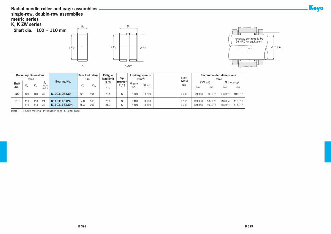
B 398
u Fw u Fw u Ew
Bc Bc
K K ZW
Radial needle roller and cage assembliessingle-row, double-row assembliesmetric seriesK, K ZW series
B 399
u S u H
raceway surfaces to be58 HRC or equivalent
Boundary dimensions
Bearing No.
Basic load ratings Fatigue Cage
material 1)
P / S
Limiting speeds(Refer.)Mass(kg)
Recommended dimensions(mm) (kN) load limit (min−1) (mm)
Shaft dia.
Fw Ew
BcCr C0r
(kN) Grease lub.
Oil lub.S (Shaft) H (Housing)
−0.20−0.55 Cu max. min. max. min.
100 100 108 30 K100X108X30 72.4 191 29.5 S 2 700 4 200 0.210 99.988 99.973 108.034 108.012
110 110 118 24 K110X118X24 64.0 168 25.6 S 2 400 3 800 0.165 109.988 109.973 118.034 118.012110 118 30 K110X118X30H 75.3 207 31.2 S 2 400 3 800 0.200 109.988 109.973 118.034 118.012
[Note] 1) Cage material: P: polymer cage, S: steel cage
Shaft dia. 100 ∼ 110 mm

Lw
u Fw u Ew
Bc
WJ, WJC
B 400
Radial needle roller and cage assembliessingle-row assembliesinch series
h5 G6
raceway surfaces to be58 HRC or equivalent
B 401
Boundary dimensions
Bearing No.
Basic load ratings Fatigue Limiting speeds Recommended dimensions(Refer.)Mass(kg)
(mm) (kN) load limit (min−1) (mm)Shaft dia.
Fw Ew
BcCr C0r
(kN) Grease lub.
Oil lub.Shaft dia. (h5) Housing bore dia. (G6)
(in) +0−0.38 Cu max. min. max. min.
3/8 9.525 12.700 9.53 WJC-060806 3.87 4.00 0.600 24 000 37 000 9.525 9.520 12.715 12.705 0.003
1/2 12.700 15.875 12.70 WJC-081008 6.23 8.01 1.65 23 000 35 000 12.700 12.692 15.890 15.880 0.005
9/16 14.288 17.463 12.70 WJC-091108 6.81 9.25 1.40 22 000 34 000 14.288 14.280 17.478 17.468 0.006
5/8 15.875 19.050 12.70 WJC-101208 7.03 9.96 1.50 18 000 27 000 15.875 15.867 19.070 19.058 0.006 15.875 22.225 15.88 WJ-101410 15.6 17.8 2.80 19 000 29 000 15.875 15.867 22.245 22.233 0.012 15.875 22.225 22.23 WJ-101414 21.3 26.4 4.10 19 000 29 000 15.875 15.867 22.245 22.233 0.017
3/4 19.050 25.400 25.40 WJ-121616 26.8 37.2 5.80 16 000 24 000 19.050 19.040 25.420 25.408 0.023
13/16 20.638 26.988 22.23 WJ-131714 25.1 35.0 5.50 14 000 22 000 20.638 20.627 27.008 26.995 0.021
7/8 22.225 28.575 25.40 WJ-141816 29.2 43.5 6.75 13 000 20 000 22.225 22.215 28.595 28.583 0.026
1 25.400 33.338 19.05 WJ-162112 28.1 37.1 5.90 12 000 18 000 25.400 25.390 33.363 33.348 0.029 25.400 33.338 25.40 WJ-162116 36.8 52.5 8.20 12 000 18 000 25.400 25.390 33.363 33.348 0.038 25.400 33.338 31.75 WJ-162120 44.5 67.2 10.5 12 000 18 000 25.400 25.390 33.363 33.348 0.048
1 1/8 28.575 38.100 25.40 WJ-182416 42.4 57.8 9.05 10 000 16 000 28.575 28.565 38.125 38.110 0.041 28.575 38.100 31.75 WJ-182420 52.0 74.7 11.7 10 000 16 000 28.575 28.565 38.125 38.110 0.065
1 1/4 31.750 41.275 19.05 WJ-202612 33.4 43.7 7.05 9 300 14 000 31.750 31.740 41.300 41.285 0.043 31.750 41.275 25.40 WJ-202616 44.1 62.3 9.80 9 300 14 000 31.750 31.740 41.300 41.285 0.061 31.750 41.275 31.75 WJ-202620 53.8 81.0 12.6 9 300 14 000 31.750 31.740 41.300 41.285 0.071
31.750 41.275 38.10 WJ-202624 63.6 99.6 15.6 9 300 14 000 31.750 31.740 41.300 41.285 0.085
1 3/8 34.925 44.450 25.40 WJ-222816 45.8 67.2 10.5 8 300 13 000 34.925 34.915 44.475 44.460 0.067 34.925 44.450 31.75 WJ-222820 56.0 87.2 13.6 8 300 13 000 34.925 34.915 44.475 44.460 0.077
1 1/2 38.100 47.625 25.40 WJ-243016 47.2 71.6 11.3 7 600 12 000 38.100 38.090 47.650 47.635 0.078 38.100 47.625 31.75 WJ-243020 57.8 93.0 14.5 7 600 12 000 38.100 38.090 47.650 47.635 0.083
[Remarks] 1) Load ratings are based on a minimum raceway hardness of 58 HRC or equivalent. 2) Minimum axial clearance should be 0.02 mm (0.008 in).
Shaft dia. 3/8 ∼ (1 1/2) in(9.525 ∼ (38.100) mm)

Lw
u Fw u Ew
Bc
WJ, WJC
B 402
Radial needle roller and cage assembliessingle-row assembliesinch series
h5 G6
raceway surfaces to be58 HRC or equivalent
B 403
Boundary dimensions
Bearing No.
Basic load ratings Fatigue Limiting speeds Recommended dimensions(Refer.)Mass(kg)
(mm) (kN) load limit (min−1) (mm)Shaft dia.
Fw Ew
BcCr C0r
(kN) Grease lub.
Oil lub.Shaft dia. (h5) Housing bore dia. (G6)
(in) +0−0.38 Cu max. min. max. min.
1 1/2 38.100 47.625 38.10 WJ-243024 68.1 114.8 18.0 7 600 12 000 38.100 38.090 47.650 47.635 0.100 38.100 47.625 44.45 WJ-243028 77.4 135.7 21.2 7 600 12 000 38.100 38.090 47.650 47.635 0.134
1 3/4 44.450 53.975 19.05 WJ-283412 39.5 59.6 9.60 6 400 9 900 44.450 44.440 54.003 53.985 0.058 44.450 53.975 25.40 WJ-283416 52.0 85.0 13.4 6 400 9 900 44.450 44.440 54.003 53.985 0.084 44.450 53.975 38.10 WJ-283424 74.7 136 21.3 6 400 9 900 44.450 44.440 54.003 53.985 0.115
2 50.800 60.325 19.05 WJ-323812 42.8 69.0 11.1 5 600 8 600 50.800 50.787 60.353 60.335 0.065 50.800 60.325 25.40 WJ-323816 56.5 98.0 15.5 5 600 8 600 50.800 50.787 60.353 60.335 0.105 50.800 60.325 31.75 WJ-323820 69.0 127 20.0 5 600 8 600 50.800 50.787 60.353 60.335 0.108
50.800 60.325 38.10 WJ-323824 81.0 157 24.6 5 600 8 600 50.800 50.787 60.353 60.335 0.130
2 1/16 52.388 61.913 25.40 WJ-333916 57.8 102 16.2 5 400 8 300 52.388 52.375 61.940 61.923 0.099
2 1/8 53.975 63.500 25.40 WJ-344016 52.5 92.08 14.6 5 200 8 000 53.975 53.962 63.528 63.510 0.089 53.975 63.500 38.10 WJ-344024 78.3 153 24.0 5 200 8 000 53.975 53.962 63.528 63.510 0.137
2 3/16 55.563 65.088 19.05 WJ-354112 44.5 75.17 12.2 5 000 7 800 55.563 55.550 65.115 65.098 0.070 55.563 65.088 25.40 WJ-354116 57.8 107 16.9 5 000 7 800 55.563 55.550 65.115 65.098 0.094
2 1/4 57.150 66.675 25.40 WJ-364216 53.8 96.08 15.2 4 900 7 500 57.150 57.137 66.703 66.685 0.096 57.150 66.675 31.75 WJ-364220 67.6 128 20.1 4 900 7 500 57.150 57.137 66.703 66.685 0.120
2 3/8 60.325 69.850 38.10 WJ-384424 81.4 167 26.1 4 600 7 100 60.325 60.312 69.878 69.860 0.151
2 1/2 63.500 73.025 25.40 WJ-404616 55.6 104 16.5 4 400 6 700 63.500 63.487 73.053 73.035 0.106 63.500 73.025 31.75 WJ-404620 69.8 139 21.8 4 400 6 700 63.500 63.487 73.053 73.035 0.132 63.500 73.025 38.10 WJ-404624 83.2 173 27.2 4 400 6 700 63.500 63.487 73.053 73.035 0.179
2 3/4 69.850 79.375 25.40 WJ-445016 57.8 112.54 17.8 4 000 6 100 69.850 69.837 79.403 79.385 0.116
3 76.200 85.725 25.40 WJ-485416 59.6 120.55 19.1 3 600 5 600 76.200 76.187 85.761 85.738 0.126 76.200 85.725 38.10 WJ-485424 85.4 191.72 29.9 3 600 5 600 76.200 76.187 85.761 85.738 0.189
[Remarks] 1) Load ratings are based on a minimum raceway hardness of 58 HRC or equivalent. 2) Minimum axial clearance should be 0.02 mm (0.008 in).
Shaft dia. (1 1/2) ∼ 3 in((38.100) ∼ 76.200 mm)

Lw
u Fw u Ew
Bc
WJ, WJC
B 404
Radial needle roller and cage assembliessingle-row assembliesinch series
h5 G6
raceway surfaces to be58 HRC or equivalent
B 405
Boundary dimensions
Bearing No.
Basic load ratings Fatigue Limiting speeds Recommended dimensions(Refer.)Mass(kg)
(mm) (kN) load limit (min−1) (mm)Shaft dia.
Fw Ew
BcCr C0r
(kN) Grease lub.
Oil lub.Shaft dia. (h5) Housing bore dia. (G6)
(in) +0−0.38 Cu max. min. max. min.
3 1/4 82.550 92.075 25.40 WJ-525816 61.4 128.55 20.4 3 300 5 100 82.550 82.535 92.111 92.088 0.136 82.550 92.075 38.10 WJ-525824 88.1 204.62 31.9 3 300 5 100 82.550 82.535 92.111 92.088 0.220
3 1/2 88.900 98.425 25.40 WJ-566216 63.2 136.56 21.7 3 100 4 700 88.900 88.885 98.461 98.438 0.146 88.900 101.600 25.40 WJ-566416 79.6 150.35 23.9 3 100 4 800 88.900 88.885 101.636 101.613 0.197 88.900 101.600 38.10 WJ-566424 113 237.53 37.4 3 100 4 800 88.900 88.885 101.636 101.613 0.296
4 101.600 114.300 25.40 WJ-647216 83.6 166.59 30.9 2 700 4 200 101.600 101.585 114.336 114.313 0.224101.600 114.300 38.10 WJ-647224 119 263.33 40.6 2 700 4 200 101.600 101.585 114.336 114.313 0.335
5 127.000 152.400 38.10 WJ-809624 211 365.20 51.9 2 200 3 400 127.000 126.982 152.438 152.415 1.018
[Remarks] 1) Load ratings are based on a minimum raceway hardness of 58 HRC or equivalent. 2) Minimum axial clearance should be 0.02 mm (0.008 in).
Shaft dia. 3 1/4 ∼ 5 in(82.550 ∼ 127.000 mm)

u Fw u D
C
HK
r
u Fw u D
C3
r
C
BK
B 406
Drawn cup needle roller bearingscaged,open ends, closed one endmetric seriesHK, BK series
u S 2) u H 2)
FullComplement
Bearing
CagedBearing
Shaft surface to be58 HRC or equivalent
B 407
Boundary dimensions
Bearing No.
Basic load ratings Fatigue Limiting speeds(Refer.)Mass(kg)
Inspection gage
Mounting inner ring(pages B458 to B467)
(mm) (kN) load limit (min−1)
Shaft dia.
Fw DC C3 r
Cr C0r
(kN) Grease lub.
Oil lub.+0−0.3 min. min. Cu
3 3 6.5 6 5.20 0.30 BK0306 1.20 0.78 0.130 30 000 46 000 0.001 Table 43 6.5 6 ⎯ 0.30 HK0306 1.60 1.14 0.130 30 000 46 000 0.001 Table 4
4 4 8 8 6.40 0.40 BK0408 1.83 1.32 0.200 25 000 39 000 0.002 Table 44 8 8 ⎯ 0.40 HK0408 1.88 1.38 0.200 25 000 39 000 0.002 Table 4
5 5 9 9 7.40 0.40 BK0509 2.52 2.07 0.320 23 000 36 000 0.002 Table 45 9 9 ⎯ 0.40 HK0509 2.52 2.07 0.320 23 000 36 000 0.002 Table 4
6 6 10 8 6.40 0.40 BK0608 2.34 1.95 0.290 22 000 33 000 0.002 Table 46 10 8 ⎯ 0.40 HK0608 2.34 1.95 0.290 22 000 33 000 0.002 Table 46 10 9 7.40 0.40 BK0609 3.14 2.85 0.290 22 000 33 000 0.003 Table 4
6 10 9 ⎯ 0.40 HK0609 3.14 2.85 0.290 22 000 33 000 0.002 Table 4
7 7 11 9 7.40 0.40 BK0709 3.24 3.10 0.470 21 000 32 000 0.003 Table 47 11 9 ⎯ 0.40 HK0709 3.23 3.05 0.470 21 000 32 000 0.003 Table 4
8 8 12 8 6.40 0.40 BK0808 2.90 2.73 0.400 20 000 31 000 0.003 Table 48 12 8 ⎯ 0.40 HK0808 2.90 2.73 0.400 20 000 31 000 0.003 Table 48 12 10 8.40 0.40 BK0810 3.93 4.14 0.600 20 000 31 000 0.004 Table 4 JR5x8x12
8 12 10 ⎯ 0.40 HK0810 3.95 4.07 0.600 20 000 31 000 0.004 Table 4 JR5x8x12
9 9 13 10 8.40 0.40 BK0910 4.57 5.07 0.770 19 000 30 000 0.004 Table 4 JR6x9x129 13 10 ⎯ 0.40 HK0910 4.57 5.07 0.770 19 000 30 000 0.004 Table 4 JR6x9x129 13 12 10.40 0.40 BK0912 5.65 6.65 1.00 19 000 30 000 0.005 Table 4 JR6x9x12
9 13 12 ⎯ 0.40 HK0912 5.65 6.65 1.00 19 000 30 000 0.005 Table 4 JR6x9x12
10 10 14 10 8.40 0.40 BK1010 4.78 5.51 0.840 19 000 29 000 0.004 Table 4 JR7x10x10,510 14 10 ⎯ 0.40 HK1010 4.78 5.51 0.840 19 000 29 000 0.004 Table 4 JR7x10x10,510 14 12 10.40 0.40 BK1012 5.90 7.23 1.10 19 000 29 000 0.006 Table 4 JR7x10x12
10 14 12 ⎯ 0.40 HK1012 5.90 7.23 1.10 19 000 29 000 0.005 Table 4 JR7x10x12
[Notes] 1) Drawn cup needle roller bearings with two needle roller and cage assemblies and one lubricating hole. 2) For the recommended mounting dimensions see Table 20.
Shaft dia. 3 ∼ (10) mm

u Fw u D
C
HK
r
u Fw u D
C3
r
C
BK
B 408
Drawn cup needle roller bearingscaged,open ends, closed one endmetric seriesHK, BK series
u S 2) u H 2)
FullComplement
Bearing
CagedBearing
Shaft surface to be58 HRC or equivalent
B 409
Boundary dimensions
Bearing No.
Basic load ratings Fatigue Limiting speeds(Refer.)Mass(kg)
Inspection gage
Mounting inner ring(pages B458 to B467)
(mm) (kN) load limit (min−1)
Shaft dia.
Fw DC C3 r
Cr C0r
(kN) Grease lub.
Oil lub.+0−0.3 min. min. Cu
10 10 14 15 13.40 0.40 BK1015 7.49 9.81 1.50 19 000 29 000 0.006 Table 4 JR7x10x1610 14 15 ⎯ 0.40 HK1015 7.49 9.81 1.50 19 000 29 000 0.006 Table 4 JR7x10x16
12 12 16 10 8.40 0.4 BK1210 4.96 6.08 0.890 18 000 28 000 0.006 Table 4 JR8x12x10,512 16 10 ⎯ 0.4 HK1210 4.96 6.08 0.890 18 000 28 000 0.006 Table 4 JR8x12x10,512 18 12 9.30 1 BK1212 6.61 7.29 1.10 14 000 22 000 0.012 Table 4 JR8x12x12,5
12 18 12 ⎯ 1 HK1212 6.61 7.29 1.10 14 000 22 000 0.01 Table 4 JR8x12x12,5
13 13 19 12 9.30 1 BK1312 6.92 7.89 1.20 14 000 22 000 0.012 Table 4 JR10x13x12,513 19 12 ⎯ 1 HK1312 6.92 7.89 1.20 14 000 22 000 0.01 Table 4 JR10x13x12,5
14 14 20 12 9.30 1 BK1412 7.21 8.50 1.30 14 000 21 000 0.014 Table 4 JR10x14x1214 20 12 ⎯ 1 HK1412 7.21 8.50 1.30 14 000 21 000 0.011 Table 4 JR10x14x12
15 15 21 12 9.30 1 BK1512 7.16 8.57 1.40 14 000 21 000 0.015 Table 4 JR12x15x12,515 21 12 ⎯ 1 HK1512 7.49 9.11 1.40 14 000 21 000 0.012 Table 4 JR12x15x12,515 21 16 13.30 1 BK1516 10.70 14.4 2.20 14 000 21 000 0.019 Table 4 JR12x15x16,5
15 21 16 ⎯ 1 HK1516 10.70 14.4 2.20 14 000 21 000 0.018 Table 4 JR12x15x16,515 21 22 19.30 1 BK1522 1) 13.50 19.4 2.95 14 000 21 000 0.022 Table 4 JR12x15x22,515 21 22 ⎯ 1 HK1522 1) 13.50 19.4 2.95 14 000 21 000 0.024 Table 4 JR12x15x22,5
16 16 22 12 9.30 1 BK1612 7.76 9.72 1.50 14 000 21 000 0.016 Table 4 JR12x16x1216 22 12 ⎯ 1 HK1612 7.76 9.72 1.50 14 000 21 000 0.012 Table 4 JR12x16x1216 22 16 13.30 1 BK1616 11.1 15.3 2.35 14 000 21 000 0.02 Table 4 JR12x16x16
16 22 16 ⎯ 1 HK1616 11.1 15.3 2.35 14 000 21 000 0.016 Table 4 JR12x16x1616 22 22 19.30 1 BK1622 1) 13.4 19.5 2.95 14 000 21 000 0.028 Table 4 JR12x16x2216 22 22 ⎯ 1 HK1622 1) 13.40 19.5 2.95 14 000 21 000 0.022 Table 4 JR12x16x22
17 17 23 12 9.30 1 BK1712 8.12 10.4 1.60 13 000 20 000 0.018 Table 417 23 12 ⎯ 1 HK1712 8.12 10.4 1.60 13 000 20 000 0.013 Table 4
18 18 24 12 9.30 1 BK1812 8.41 11.11 1.70 12 000 18 000 0.017 Table 4
[Notes] 1) Drawn cup needle roller bearings with two needle roller and cage assemblies and one lubricating hole. 2) For the recommended mounting dimensions see Table 20.
Shaft dia. (10) ∼ (18) mm

u Fw u D
C
HK
r
u Fw u D
C3
r
C
BK
B 410
Drawn cup needle roller bearingscaged,open ends, closed one endmetric seriesHK, BK series
u S 2) u H 2)
FullComplement
Bearing
CagedBearing
Shaft surface to be58 HRC or equivalent
B 411
Boundary dimensions
Bearing No.
Basic load ratings Fatigue Limiting speeds(Refer.)Mass(kg)
Inspection gage
Mounting inner ring(pages B458 to B467)
(mm) (kN) load limit (min−1)
Shaft dia.
Fw DC C3 r
Cr C0r
(kN) Grease lub.
Oil lub.+0−0.3 min. min. Cu
18 18 24 12 ⎯ 1 HK1812 8.41 11.11 1.70 12 000 18 000 0.015 Table 418 24 16 13.30 1 BK1816 11.6 16.8 2.55 12 000 18 000 0.022 Table 4 JR15x18x16,518 24 16 ⎯ 1 HK1816 11.6 16.8 2.55 12 000 18 000 0.018 Table 4 JR15x18x16,5
20 20 26 12 9.3 1 BK2012 8.97 12.5 1.90 11 000 16 000 0.017 Table 4 JR15x20x1220 26 12 ⎯ 1 HK2012 8.97 12.5 1.90 11 000 16 000 0.015 Table 4 JR15x20x1220 26 16 13.3 1 BK2016 12.40 18.90 2.85 11 000 16 000 0.024 Table 4 JR17x20x16,5
20 26 16 ⎯ 1 HK2016 12.40 18.90 2.85 11 000 16 000 0.022 Table 4 JR17x20x16,520 26 20 17.3 1 BK2020 15.50 25.30 3.95 11 000 16 000 0.027 Table 4 JR17x20x20,520 26 20 ⎯ 1 HK2020 15.90 26.20 3.95 11 000 16 000 0.025 Table 4 JR17x20x20,5
20 26 30 27.3 1 BK2030 1) 21.20 37.80 5.75 11 000 16 000 0.043 Table 4 JR17x20x30,520 26 30 ⎯ 1 HK2030 1) 21.20 37.80 5.75 11 000 16 000 0.041 Table 4 JR17x20x30,5
22 22 28 10 8.4 1 BK2210 7.06 9.49 1.45 9 600 15 000 0.013 Table 422 28 10 ⎯ 1 HK2210 7.06 9.49 1.45 9 600 15 000 0.013 Table 422 28 12 9.3 1 BK2212 9.81 14.50 2.20 9 600 15 000 0.02 Table 4 JR17x22x13
22 28 12 ⎯ 1 HK2212 9.81 14.50 2.20 9 600 15 000 0.015 Table 4 JR17x22x1322 28 16 13.3 1 BK2216 13.10 20.90 3.20 9 600 15 000 0.027 Table 4 JR17x22x1622 28 16 ⎯ 1 HK2216 13.10 20.90 3.20 9 600 15 000 0.022 Table 4 JR17x22x16
22 28 20 17.3 1 BK2220 15.30 25.50 4.00 9 600 15 000 0.028 Table 4 JR17x22x2322 28 20 ⎯ 1 HK2220 15.30 25.50 4.00 9 600 15 000 0.026 Table 4 JR17x22x23
25 25 32 12 9.30 1 BK2512 10.90 14.70 2.25 8 500 13 000 0.025 Table 425 32 12 ⎯ 1 HK2512 10.90 14.70 2.25 8 500 13 000 0.021 Table 425 32 16 13.3 1 BK2516 15.60 23.50 3.55 8 500 13 000 0.031 Table 4 JR20x25x17
25 32 16 ⎯ 1 HK2516 15.60 23.50 3.55 8 500 13 000 0.028 Table 4 JR20x25x1725 32 20 17.3 1 BK2520 20.60 33.40 5.30 8 500 13 000 0.043 Table 4 JR20x25x20,525 32 20 ⎯ 1 HK2520 20.60 33.40 5.30 8 500 13 000 0.040 Table 4 JR20x25x20,5
25 32 26 23.3 1 BK2526 25.70 44.40 6.95 8 500 13 000 0.051 Table 4 JR20x25x26,525 32 26 ⎯ 1 HK2526 25.70 44.40 6.95 8 500 13 000 0.046 Table 4 JR20x25x26,5
[Notes] 1) Drawn cup needle roller bearings with two needle roller and cage assemblies and one lubricating hole. 2) For the recommended mounting dimensions see Table 20.
Shaft dia. (18) ∼ (25) mm

u Fw u D
C
HK
r
u Fw u D
C3
r
C
BK
B 412
Drawn cup needle roller bearingscaged,open ends, closed one endmetric seriesHK, BK series
u S 2) u H 2)
FullComplement
Bearing
CagedBearing
Shaft surface to be58 HRC or equivalent
B 413
Boundary dimensions
Bearing No.
Basic load ratings Fatigue Limiting speeds(Refer.)Mass(kg)
Inspection gage
Mounting inner ring(pages B458 to B467)
(mm) (kN) load limit (min−1)
Shaft dia.
Fw DC C3 r
Cr C0r
(kN) Grease lub.
Oil lub.+0−0.3 min. min. Cu
25 25 32 38 35.3 1 BK2538 1) 35.30 66.90 10.6 8 500 13 000 0.077 Table 4 JR20x25x38,525 32 38 ⎯ 1 HK2538 1) 35.30 66.90 10.6 8 500 13 000 0.068 Table 4 JR20x25x38,5
28 28 35 16 13.30 1 BK2816 15.9 24.9 3.85 7 500 12 000 0.038 Table 4 JR22x28x1728 35 16 ⎯ 1 HK2816 15.9 24.9 3.85 7 500 12 000 0.032 Table 4 JR22x28x1728 35 20 17.3 1 BK2820 20.9 35.3 5.60 7 500 12 000 0.047 Table 4 JR22x28x20,5
28 35 20 ⎯ 1 HK2820 20.9 35.3 5.60 7 500 12 000 0.040 Table 4 JR22x28x20,5
30 30 37 12 9.3 1 BK3012 11.6 16.8 2.90 7 000 11 000 0.031 Table 430 37 12 ⎯ 1 HK3012 12.0 17.7 2.70 7 000 11 000 0.024 Table 430 37 16 13.30 1 BK3016 16.8 27.3 4.20 7 000 11 000 0.041 Table 4 JR25x30x17
30 37 16 ⎯ 1 HK3016 16.8 27.3 4.20 7 000 11 000 0.032 Table 4 JR25x30x1730 37 20 17.3 1 BK3020 22.4 39.6 6.25 7 000 11 000 0.053 Table 4 JR25x30x20,530 37 20 ⎯ 1 HK3020 22.4 39.6 6.25 7 000 11 000 0.042 Table 4 JR25x30x20,5
30 37 26 23.3 1 BK3026 27.4 51.2 7.95 7 000 11 000 0.067 Table 4 JR25x30x26,530 37 26 ⎯ 1 HK3026 27.4 51.2 7.95 7 000 11 000 0.054 Table 4 JR25x30x26,530 37 38 35.3 1 BK3038 1) 38.4 79.2 12.5 7 000 11 000 0.093 Table 4 JR25x30x38,5
30 37 38 ⎯ 1 HK3038 1) 38.4 79.2 12.5 7 000 11 000 0.075 Table 4 JR25x30x38,5
35 35 42 12 ⎯ 1 HK3512 13.0 20.6 2.90 5 900 9 100 0.028 Table 435 42 16 ⎯ 1 HK3516 17.4 29.9 4.60 5 900 9 100 0.037 Table 4 JR30x35x1735 42 20 17.3 1 BK3520 24.5 46.8 7.40 5 900 9 100 0.065 Table 4 JR30x35x20,5
35 42 20 ⎯ 1 HK3520 24.5 46.8 7.40 5 900 9 100 0.049 Table 4 JR30x35x20,5
40 40 47 12 ⎯ 1 HK4012 14.7 25.3 3.40 5 200 7 900 0.033 Table 440 47 16 ⎯ 1 HK4016 18.9 34.8 5.35 5 200 7 900 0.042 Table 4 JR35x40x1740 47 20 17.3 1 BK4020 25.1 50.4 8.00 5 200 7 900 0.070 Table 4 JR35x40x20,5
40 47 20 ⎯ 1 HK4020 25.1 50.4 8.00 5 200 7 900 0.060 Table 4 JR35x40x20,5
45 45 52 12 ⎯ 1 HK4512 14.1 24.8 3.75 4 600 7 000 0.036 Table 4
[Notes] 1) Drawn cup needle roller bearings with two needle roller and cage assemblies and one lubricating hole. 2) For the recommended mounting dimensions see Table 20.
Shaft dia. (25) ∼ (45) mm

u Fw u D
C
HK
r
u Fw u D
C3
r
C
BK
B 414
Drawn cup needle roller bearingscaged,open ends, closed one endmetric seriesHK, BK series
u S 2) u H 2)
FullComplement
Bearing
CagedBearing
Shaft surface to be58 HRC or equivalent
B 415
Boundary dimensions
Bearing No.
Basic load ratings Fatigue Limiting speeds(Refer.)Mass(kg)
Inspection gage
Mounting inner ring(pages B458 to B467)
(mm) (kN) load limit (min−1)
Shaft dia.
Fw DC C3 r
Cr C0r
(kN) Grease lub.
Oil lub.+0−0.3 min. min. Cu
45 45 52 16 ⎯ 1 HK4516 19.8 38.5 5.95 4 600 7 000 0.048 Table 4 JR40x45x1745 52 20 17.3 1 BK4520 26.3 55.4 8.80 4 600 7 000 0.079 Table 4 JR40x45x20,545 52 20 ⎯ 1 HK4520 27.2 58.2 8.80 4 600 7 000 0.059 Table 4 JR40x45x20,5
50 50 58 12 ⎯ 1 HK5012 17.0 28.7 4.40 4 100 6 300 0.045 Table 450 58 20 ⎯ 1 HK5020 30.9 62.2 8.80 4 100 6 300 0.072 Table 4 JR45x50x2050 58 25 ⎯ 1 HK5025 35.5 74.1 11.7 4 100 6 300 0.092 Table 4 JR45x50x25,5
55 55 63 20 ⎯ 1 HK5520 31.0 64.4 10.0 3 700 5 700 0.079 Table 4
60 60 68 12 ⎯ 1 HK6012 18.6 34.4 5.25 3 400 5 200 0.060 Table 460 68 20 ⎯ 1 HK6020 32.5 70.2 10.9 3 400 5 200 0.090 Table 4
[Notes] 1) Drawn cup needle roller bearings with two needle roller and cage assemblies and one lubricating hole. 2) For the recommended mounting dimensions see Table 20.
Shaft dia. (45) ∼ 60 mm

C
u D u Fw
J, JH MJ-1, MJH-1
Y
C
u Fwu D
B 416
Drawn cup needle roller bearingscaged,open ends, closed one endinch seriesJ, JH, MJ-1, MJH-1 series
u S 1) u H 1)
Shaft surface to be58 HRC or equivalent
FullComplement
Bearing
CagedBearing
B 417
Boundary dimensions Bearing No. Basic load ratings Fatigue Limiting speeds (Refer.) Mass(kg) Inspection
gage(mm) (kN) load limit (min−1)
Shaft dia.Fw D
C Ymax.
With open ends With closed end Cr C0r
(kN) Grease lub.
Oil lub.With open
endsWith closed
end(in) +0−0.3 Cu
1/8 3.175 6.350 4.78 ⎯ JP-23-F ⎯ 0.89 0.62 0.100 33 000 51 000 0.001 ⎯ Table 5 3.175 6.350 6.35 ⎯ JP-24-F ⎯ 1.33 1.02 0.150 33 000 51 000 0.001 ⎯ Table 5
5/32 3.970 7.142 4.78 ⎯ JP-2 1/2 3F ⎯ 0.93 0.62 0.110 31 000 47 000 0.001 ⎯ Table 5
3/16 4.763 8.733 4.77 ⎯ JP-33-F ⎯ 1.07 0.71 0.120 25 000 38 000 0.001 ⎯ Table 5 4.763 8.733 6.35 ⎯ JP-34-F ⎯ 1.60 1.25 0.200 25 000 38 000 0.001 ⎯ Table 5 4.763 8.733 9.53 1.02 J-36 MJ-361 2.27 1.91 0.290 25 000 38 000 0.002 0.002 Table 5
1/4 6.350 11.113 7.92 1.02 J-45 MJ-451 2.22 1.73 0.300 20 000 30 000 0.003 0.003 Table 5 6.350 11.113 11.13 1.02 J-47 MJ-471 3.38 3.02 0.450 20 000 30 000 0.004 0.004 Table 5
5/16 7.938 12.700 7.92 ⎯ J-55 ⎯ 2.40 2.00 0.340 18 000 28 000 0.003 ⎯ Table 5 7.938 12.700 11.13 1.02 J-57 MJ-571 4.05 3.91 0.590 18 000 28 000 0.004 0.005 Table 5 7.938 14.288 11.13 1.02 JH-57 MJH-571 4.63 3.78 0.570 14 000 22 000 0.006 0.007 Table 5
3/8 9.525 14.288 7.92 1.02 J-65 MJ-651 2.76 2.49 0.430 18 000 27 000 0.004 0.004 Table 5 9.525 14.288 9.53 1.02 J-66 MJ-661 3.51 3.47 0.530 18 000 27 000 0.004 0.005 Table 5 9.525 14.288 12.70 1.02 J-68 MJ-681 5.20 5.74 0.860 18 000 27 000 0.005 0.006 Table 5
9.525 15.875 12.70 ⎯ JH-68 ⎯ 6.58 6.09 0.920 13 000 20 000 0.008 ⎯ Table 5
7/16 11.113 15.875 12.70 1.02 J-78 MJ-781 6.36 7.70 1.15 17 000 26 000 0.006 0.007 Table 5 11.113 17.463 12.70 ⎯ JH-78 ⎯ 7.12 6.89 1.05 13 000 19 000 0.009 ⎯ Table 5
1/2 12.700 17.463 7.92 1.02 J-85 MJ-851 3.47 3.65 0.630 16 000 25 000 0.005 0.005 Table 512.700 17.463 9.53 1.02 J-86 MJ-861 4.67 5.38 0.830 16 000 25 000 0.005 0.006 Table 512.700 17.463 12.70 1.02 J-88 MJ-881 6.32 7.92 1.20 16 000 25 000 0.007 0.008 Table 5
12.700 17.463 19.05 ⎯ J-812 ⎯ 10.23 14.72 2.25 16 000 25 000 0.010 ⎯ Table 512.700 19.050 11.13 1.02 JH-87 MJH-871 6.41 6.18 0.950 12 000 19 000 0.009 0.010 Table 512.700 19.050 12.70 1.02 JH-88 MJH-881 7.56 7.70 1.15 12 000 19 000 0.010 0.012 Table 5
12.700 19.050 19.05 ⎯ JH-812 ⎯ 12.32 14.41 2.25 12 000 19 000 0.015 ⎯ Table 5
[Note] 1) For the recommended mounting dimensions see Table 21.
Shaft dia. 1/8 ∼ 1/2 in(3.175 ∼ 12.700 mm)

C
u D u Fw
J, JH MJ-1, MJH-1
Y
C
u Fwu D
B 418
Drawn cup needle roller bearingscaged,open ends, closed one endinch seriesJ, JH, MJ-1, MJH-1 series
u S 1) u H 1)
Shaft surface to be58 HRC or equivalent
FullComplement
Bearing
CagedBearing
B 419
Boundary dimensions Bearing No. Basic load ratings Fatigue Limiting speeds (Refer.) Mass(kg) Inspection
gage(mm) (kN) load limit (min−1)
Shaft dia.Fw D
C Ymax.
With open ends With closed end Cr C0r
(kN) Grease lub.
Oil lub.With open
endsWith closed
end(in) +0−0.3 Cu
9/16 14.288 19.050 11.13 1.02 J-97 MJ-971 5.47 6.81 1.05 16 000 25 000 0.007 0.009 Table 514.288 19.050 12.70 1.02 J-98 MJ-981 6.23 8.01 1.20 16 000 25 000 0.008 0.009 Table 514.288 19.050 15.88 ⎯ J-910 ⎯ 5.83 7.21 1.75 16 000 25 000 0.010 ⎯ Table 5
14.288 20.638 12.70 1.02 JH-98 MJH-981 8.01 8.50 1.30 12 000 18 000 0.011 0.014 Table 5
5/8 15.875 20.638 12.70 1.02 J-108 MJ-1081 6.72 9.12 1.40 13 000 21 000 0.009 0.010 Table 515.875 20.638 15.88 1.02 J-1010 MJ-10101 8.81 12.94 1.95 13 000 21 000 0.010 0.013 Table 515.875 20.638 19.05 1.02 J-1012 MJ-10121 11.74 18.86 2.90 13 000 21 000 0.013 0.015 Table 5
15.875 22.212 15.88 1.02 JH-1010 MJH-10101 11.57 14.10 2.15 14 000 21 000 0.015 0.017 Table 515.875 22.212 25.40 1.02 JH-1016 MJH-10161 19.79 28.11 4.35 14 000 21 000 0.024 0.028 Table 5
11/16 17.463 22.212 19.05 1.02 J-1112 MJ-11121 12.46 20.91 3.20 12 000 19 000 0.014 0.016 Table 517.463 23.813 15.88 1.02 JH-1110 MJH-11101 12.05 15.21 2.30 13 000 19 000 0.016 0.019 Table 517.463 23.813 19.05 ⎯ JH-1112 ⎯ 16.15 22.20 3.10 13 000 19 000 0.019 ⎯ Table 5
3/4 19.050 25.400 9.53 ⎯ J-126 ⎯ 6.49 7.03 1.10 11 000 18 000 0.010 ⎯ Table 519.050 25.400 12.70 ⎯ J-128 ⎯ 9.92 12.19 1.85 11 000 18 000 0.014 ⎯ Table 519.050 25.400 15.88 1.02 J-1210 MJ-12101 12.50 16.32 2.50 11 000 18 000 0.017 0.020 Table 5
19.050 25.400 19.05 1.02 J-1212 MJ-12121 15.52 21.62 3.35 11 000 18 000 0.020 0.025 Table 519.050 26.988 19.05 1.02 JH-1212 MJH-12121 19.08 23.58 3.70 12 000 18 000 0.026 0.031 Table 5
13/16 20.638 26.988 22.23 ⎯ J-1314 ⎯ 19.31 29.31 4.55 10 000 16 000 0.025 ⎯ Table 520.638 28.575 19.05 1.27 JH-1312 MJH-13121 18.77 24.55 3.85 11 000 16 000 0.028 0.034 Table 5
7/8 22.225 28.575 9.53 ⎯ J-146 ⎯ 7.21 8.41 1.30 9 700 15 000 0.012 ⎯ Table 522.225 28.575 12.70 ⎯ J-148 ⎯ 10.94 14.50 2.20 9 700 15 000 0.015 ⎯ Table 522.225 28.575 19.05 1.02 J-1412 MJ-14121 17.88 27.18 4.20 9 700 15 000 0.024 0.028 Table 5
22.225 28.575 25.40 1.02 J-1416 MJ-14161 23.66 38.97 6.05 9 700 15 000 0.031 0.059 Table 522.225 30.163 19.05 1.27 JH-1412 MJH-14121 18.33 24.55 3.75 9 800 15 000 0.030 0.036 Table 522.225 30.163 25.40 1.27 JH-1416 MJH-14161 25.40 37.37 5.80 9 800 15 000 0.040 0.048 Table 5
[Note] 1) For the recommended mounting dimensions see Table 21.
Shaft dia. 9/16 ∼ 7/8 in(14.288 ∼ 22.225 mm)

C
u D u Fw
J, JH MJ-1, MJH-1
Y
C
u Fwu D
B 420
Drawn cup needle roller bearingscaged,open ends, closed one endinch seriesJ, JH, MJ-1, MJH-1 series
u S 1) u H 1)
Shaft surface to be58 HRC or equivalent
FullComplement
Bearing
CagedBearing
B 421
Boundary dimensions Bearing No. Basic load ratings Fatigue Limiting speeds (Refer.) Mass(kg) Inspection
gage(mm) (kN) load limit (min−1)
Shaft dia.Fw D
C Ymax.
With open ends With closed end Cr C0r
(kN) Grease lub.
Oil lub.With open
endsWith closed
end(in) +0−0.3 Cu
1 25.400 31.750 19.05 ⎯ J-1612 ⎯ 18.15 28.82 4.45 8 400 13 000 0.026 ⎯ Table 525.400 31.750 25.40 1.02 J-1616 MJ-16161 24.95 43.41 6.75 8 400 13 000 0.035 0.042 Table 525.400 33.338 19.05 1.27 JH-1612 MJH-16121 20.68 29.58 4.60 8 500 13 000 0.034 0.040 Table 5
25.400 33.338 25.40 1.27 JH-1616 MJH-16161 27.58 42.88 6.65 8 500 13 000 0.045 0.054 Table 5
1 1/8 28.575 34.925 12.70 1.02 J-188 MJ-1881 11.65 16.95 2.55 7 400 11 000 0.020 0.023 Table 528.575 34.925 19.05 1.02 J-1812 MJ-18121 19.04 31.76 4.90 7 400 11 000 0.029 0.035 Table 528.575 34.925 25.40 1.02 J-1816 MJ-18161 26.16 48.04 7.40 7 400 11 000 0.039 0.047 Table 5
28.575 38.100 19.05 1.27 JH-1812 MJH-18121 23.35 31.32 4.75 7 600 12 000 0.046 0.055 Table 528.575 38.100 25.40 1.27 JH-1816 MJH-18161 33.14 49.38 7.70 7 600 12 000 0.061 0.074 Table 528.575 38.100 28.58 1.27 JH-1818 MJH-18181 36.30 55.16 8.60 7 600 12 000 0.069 0.082 Table 5
1 1/4 31.750 38.100 19.05 1.02 J-2012 MJ-20121 19.84 34.70 5.35 6 600 10 000 0.036 0.043 Table 531.750 38.100 25.40 1.02 J-2016 MJ-20161 28.82 56.49 8.70 6 600 10 000 0.043 0.051 Table 531.750 41.275 19.05 ⎯ JH-2012 ⎯ 24.11 33.94 5.80 6 800 10 000 0.050 ⎯ Table 5
31.750 41.275 25.40 ⎯ JH-2016 ⎯ 33.94 52.93 8.20 6 800 10 000 0.067 ⎯ Table 531.750 41.275 31.75 ⎯ JH-2020 ⎯ 43.37 72.51 10.8 6 800 10 000 0.084 ⎯ Table 5
1 3/8 34.925 41.275 12.70 1.02 J-228 MJ-2281 13.97 22.91 3.50 6 000 9 200 0.024 0.028 Table 534.925 41.275 19.05 ⎯ J-2212 ⎯ 22.82 42.97 6.65 6 000 9 200 0.035 ⎯ Table 534.925 44.450 19.05 1.27 JH-2212 MJH-22121 26.24 38.43 5.90 6 100 9 400 0.055 0.065 Table 5
34.925 44.450 25.40 1.27 JH-2216 MJH-22161 36.52 58.72 9.20 6 100 9 400 0.073 0.087 Table 5
1 1/2 38.100 47.625 19.05 1.27 J-2412 MJ-24121 29.89 47.15 7.40 5 600 8 600 0.059 0.094 Table 538.100 47.625 25.40 1.27 J-2416 MJ-24161 39.32 66.72 10.4 5 600 8 600 0.079 0.094 Table 538.100 47.625 31.75 ⎯ J-2420 ⎯ 49.38 89.85 14.0 5 600 8 600 0.099 ⎯ Table 5
1 5/8 41.275 50.800 15.88 ⎯ J-2610 ⎯ 26.11 40.97 6.25 5 100 7 900 0.053 ⎯ Table 541.275 50.800 25.40 1.27 J-2616 M-26161 39.28 68.95 10.8 5 100 7 900 0.085 0.101 Table 5
1 3/4 44.450 53.975 19.05 1.27 J-2812 MJ-28121 29.58 49.38 7.45 4 700 7 300 0.068 0.081 Table 5
[Note] 1) For the recommended mounting dimensions see Table 21.
Shaft dia. 1 ∼ (1 3/4) in(25.400 ∼ (44.450) mm)

C
u D u Fw
J, JH MJ-1, MJH-1
Y
C
u Fwu D
B 422
Drawn cup needle roller bearingscaged,open ends, closed one endinch seriesJ, JH, MJ-1, MJH-1 series
u S 1) u H 1)
Shaft surface to be58 HRC or equivalent
FullComplement
Bearing
CagedBearing
B 423
Boundary dimensions Bearing No. Basic load ratings Fatigue Limiting speeds (Refer.) Mass(kg) Inspection
gage(mm) (kN) load limit (min−1)
Shaft dia.Fw D
C Ymax.
With open ends With closed end Cr C0r
(kN) Grease lub.
Oil lub.With open
endsWith closed
end(in) +0−0.3 Cu
1 3/4 44.450 53.975 25.40 1.27 J-2816 MJ-28161 40.08 72.95 11.4 4 700 7 300 0.091 0.108 Table 544.450 53.975 38.10 1.27 J-2824 MJ-28241 59.61 121.88 18.9 4 700 7 300 0.136 0.162 Table 5
1 7/8 47.625 57.150 25.40 1.27 J-3016 MJ-30161 41.10 76.06 11.9 4 400 6 800 0.097 0.115 Table 5
2 50.800 60.325 25.40 1.27 J-3216 MJ-32161 42.39 81.40 12.7 4 100 6 300 0.103 0.137 Table 5
2 1/4 57.150 66.675 19.05 ⎯ J-3612 ⎯ 35.41 65.83 10.0 3 600 5 600 0.086 ⎯ Table 557.150 66.675 25.40 ⎯ J-3616 ⎯ 46.26 92.52 14.4 3 600 5 600 0.114 ⎯ Table 5
2 3/4 69.850 79.375 19.05 ⎯ J-4412 ⎯ 36.25 72.95 11.3 2 900 4 500 0.103 ⎯ Table 5
[Note] 1) For the recommended mounting dimensions see Table 21.
Shaft dia. (1 3/4) ∼ 2 3/4 in((44.450) ∼ 69.850 mm)

NK (uFw ≤ 10) NK (uFw ≥ 12), NKS, RNA48, RNA49, RNA69 (uFw ≤ 35)
C
u Fw
r
u D
r
u Fw u D
C
B 424
Heavy-duty needle roller bearingswithout inner ringsmetric seriesNK, NKS, RNA48, RNA49RNA69, NKTN series
r
u Fw u D
C
RNA69(uFw ≥ 40)
r
u Fw u D
C
NKTN
B 425
Boundary dimensions
Bearing No.
Basic load ratings Fatigue Limiting speeds(Refer.)Mass(kg)
(mm) (kN) load limit (min−1)Shaft dia.
Fw D C rmin.
Cr C0r(kN) Grease
lub.Oil lub.
Cu
5 5 10 10 0.2 NK5/10TN 2.18 1.71 0.260 31 000 47 000 0.004 5 10 12 0.2 NK5/12TN 3.04 2.63 0.400 31 000 47 000 0.004
6 6 12 10 0.2 NK6/10 3.19 2.90 0.420 29 000 44 000 0.005 6 12 12 0.2 NK6/12TN 3.07 2.74 0.420 29 000 44 000 0.006
7 7 14 10 0.3 NK7/10TN 2.74 2.44 0.370 28 000 42 000 0.007 7 14 12 0.3 NK7/12TN 3.40 3.22 0.490 28 000 42 000 0.009
8 8 15 12 0.3 NK8/12 4.57 4.89 0.740 26 000 41 000 0.011 8 15 12 0.3 NK8/12ASR1 4.57 4.89 0.740 26 000 41 000 0.011 8 15 16 0.3 NK8/16 5.22 5.78 0.880 26 000 41 000 0.013
9 9 16 12 0.3 NK9/12 4.27 4.60 0.700 26 000 40 000 0.012 9 16 16 0.3 NK9/16 5.57 6.47 0.980 26 000 40 000 0.015
10 10 17 12 0.3 NK10/12 5.40 6.43 0.980 25 000 39 000 0.013 10 17 16 0.3 NK10/16TN 5.30 6.27 0.940 25 000 39 000 0.015
12 12 19 12 0.3 NK12/12 6.86 7.60 1.15 19 000 30 000 0.013 12 19 16 0.3 NK12/16 6.78 9.03 1.40 24 000 37 000 0.018
14 14 22 13 0.3 RNA4900 9.39 10.3 1.55 16 000 24 000 0.018 14 22 16 0.3 NK14/16 12.4 14.8 2.25 16 000 24 000 0.023 14 22 20 0.3 NK14/20 14.7 18.4 2.90 16 000 24 000 0.028
15 15 23 16 0.3 NK15/16 12.4 15.0 2.30 15 000 24 000 0.024 15 23 20 0.3 NK15/20 14.7 18.6 2.95 15 000 24 000 0.031
16 16 24 13 0.3 RNA4901 10.5 12.3 1.85 18 000 28 000 0.020 16 24 16 0.3 NK16/16 15.4 20.2 2.50 18 000 28 000 0.025 16 24 20 0.3 NK16/20 16.1 21.3 3.20 18 000 28 000 0.036
16 24 22 0.3 RNA6901 16.1 21.3 3.30 18 000 28 000 0.036
17 17 25 16 0.3 NK17/16 13.6 17.5 2.70 17 000 27 000 0.027
Boundary dimensions
Bearing No.
Basic load ratings Fatigue Limiting speeds(Refer.)Mass(kg)
(mm) (kN) load limit (min−1)Shaft dia.
Fw D C rmin.
Cr C0r(kN) Grease
lub.Oil lub.
Cu
17 17 25 20 0.3 NK17/20 15.4 20.4 3.25 17 000 27 000 0.034
18 18 26 16 0.3 NK18/16 13.6 17.7 2.70 16 000 25 000 0.028 18 26 20 0.3 NK18/20 16.1 22.0 3.50 16 000 25 000 0.035
19 19 27 16 0.3 NK19/16 14.1 19.0 2.90 15 000 24 000 0.029 19 27 20 0.3 NK19/20 18.8 23.6 3.75 15 000 24 000 0.037 19 30 16 0.3 NKS18 15.9 16.2 2.45 17 000 26 000 0.045
20 20 28 13 0.3 RNA4902 11.8 15.3 2.35 14 000 22 000 0.023 20 28 16 0.3 NK20/16 14.1 19.1 2.90 14 000 22 000 0.030 20 28 20 0.3 NK20/20 17.5 25.3 4.00 14 000 22 000 0.038
20 28 23 0.3 RNA6902 18.4 26.9 4.20 14 000 22 000 0.042 20 32 20 0.6 NKS20 24.4 26.7 4.30 15 000 24 000 0.058
21 21 29 16 0.3 NK21/16 15.3 21.6 3.30 14 000 21 000 0.032 21 29 20 0.3 NK21/20 18.1 26.9 4.25 14 000 21 000 0.040
22 22 30 13 0.3 RNA4903 12.2 16.4 2.50 13 000 20 000 0.025 22 30 16 0.3 NK22/16 15.2 21.7 3.30 13 000 20 000 0.033 22 30 20 0.3 NK22/20 18.0 27.0 4.30 13 000 20 000 0.041
22 30 23 0.3 RNA6903 19.8 30.6 4.75 13 000 20 000 0.056 22 35 20 0.6 NKS22 22.9 27.1 4.30 14 000 21 000 0.069
24 24 32 16 0.3 NK24/16 16.2 24.3 3.70 12 000 18 000 0.035 24 32 20 0.3 NK24/20 19.3 30.3 4.80 12 000 18 000 0.045 24 37 20 0.6 NKS24 29.1 32.8 5.30 13 000 20 000 0.073
25 25 33 16 0.3 NK25/16 16.1 24.4 3.75 11 000 17 000 0.037 25 33 20 0.3 NK25/20 19.1 30.4 4.80 11 000 17 000 0.047 25 37 17 0.3 RNA4904 21.3 25.5 3.95 12 000 18 000 0.061
25 37 30 0.3 RNA6904 36.6 51.0 7.95 12 000 18 000 0.091 25 38 20 0.6 NKS25 29.1 33.0 5.30 12 000 19 000 0.076
Shaft dia. 5 ∼ (17) mm
Shaft dia. (17) ∼ 25 mm

NK (uFw ≤ 10) NK (uFw ≥ 12), NKS, RNA48, RNA49, RNA69 (uFw ≤ 35)
C
u Fw
r
u D
r
u Fw u D
C
B 426
Heavy-duty needle roller bearingswithout inner ringsmetric seriesNK, NKS, RNA48, RNA49RNA69, NKTN series
r
u Fw u D
C
RNA69(uFw ≥ 40)
r
u Fw u D
C
NKTN
B 427
Boundary dimensions
Bearing No.
Basic load ratings Fatigue Limiting speeds(Refer.)Mass(kg)
(mm) (kN) load limit (min−1)Shaft dia.
Fw D C rmin.
Cr C0r(kN) Grease
lub.Oil lub.
Cu
26 26 34 16 0.3 NK26/16 16.6 25.7 3.95 11 000 17 000 0.039 26 34 20 0.3 NK26/20 19.7 32.0 5.05 11 000 17 000 0.048
28 28 37 20 0.3 NK28/20 22.6 34.4 5.50 10 000 16 000 0.057 28 37 30 0.3 NK28/30 29.0 53.8 8.30 10 000 16 000 0.088 28 39 17 0.3 RNA49/22 23.3 29.6 4.55 10 000 16 000 0.059
28 39 30 0.3 RNA69/22 30.6 50.7 3.95 10 000 16 000 0.107 28 42 20 0.6 NKS28 30.3 38.4 6.15 11 000 16 000 0.094
29 29 38 20 0.3 NK29/20 23.4 36.4 5.80 9 800 15 000 0.059 29 38 30 0.3 NK29/30 29.8 56.4 8.70 9 700 15 000 0.090
30 30 40 20 0.3 NK30/20 24.2 38.3 6.10 9 500 15 000 0.071 30 40 30 0.3 NK30/30 34.7 61.0 9.45 9 500 15 000 0.107 30 42 17 0.3 RNA4905 24.3 31.7 4.90 9 700 15 000 0.071
30 42 30 0.3 RNA6905 39.7 59.6 9.30 9 700 15 000 0.127 30 45 20 0.6 NKS30 34.3 42.8 6.85 9 900 15 000 0.114
32 32 42 20 0.3 NK32/20 24.8 40.4 6.45 8 800 14 000 0.074 32 42 30 0.3 NK32/30 35.6 64.3 9.95 8 800 14 000 0.112 32 45 17 0.3 RNA49/28 25.1 33.8 5.20 9 000 14 000 0.080
32 45 30 0.3 RNA69/28 43.2 62.5 9.75 9 100 14 000 0.140 32 47 22 0.6 NKS32 36.0 46.2 7.40 9 200 14 000 0.120
35 35 45 20 0.3 NK35/20 26.1 44.4 7.05 8 000 12 000 0.081 35 45 30 0.3 NK35/30 37.4 70.6 11.0 8 000 12 000 0.122 35 47 18 0.3 RNA4906 25.9 36.0 5.55 8 200 13 000 0.081
35 47 30 0.3 RNA6906 42.6 68.2 10.6 8 200 13 000 0.148 35 50 22 0.6 NKS35 37.5 49.9 8.00 8 400 13 000 0.130
37 37 47 20 0.3 NK37/20 26.6 46.4 7.40 7 600 12 000 0.084 37 47 30 0.3 NK37/30 38.2 73.9 11.5 7 600 12 000 0.128 37 52 22 0.6 NKS37 39.0 53.4 8.55 7 900 12 000 0.134
Boundary dimensions
Bearing No.
Basic load ratings Fatigue Limiting speeds(Refer.)Mass(kg)
(mm) (kN) load limit (min−1)Shaft dia.
Fw D C rmin.
Cr C0r(kN) Grease
lub.Oil lub.
Cu
38 38 48 20 0.3 NK38/20 21.7 40.9 6.40 7 300 11 000 0.087 38 48 30 0.3 NK38/30 31.9 67.0 10.4 7 300 11 000 0.131
40 40 50 20 0.3 NK40/20 27.8 50.4 8.05 7 000 11 000 0.089 40 50 30 0.3 NK40/30 40.0 80.2 12.4 7 000 11 000 0.137 40 52 20 0.6 RNA49/32 32.0 49.3 7.85 7 100 11 000 0.100
40 52 36 0.6 RNA69/32 48.6 84.5 26.1 7 100 11 000 0.185 40 55 22 0.6 NKS40 40.3 57.0 9.15 7 200 11 000 0.140
42 42 52 20 0.3 NK42/20 28.3 52.4 8.35 6 600 10 000 0.085 42 52 30 0.3 NK42/30 40.7 83.5 13.0 6 600 10 000 0.141 42 55 20 0.6 RNA4907 32.8 51.7 8.25 6 700 10 000 0.114
42 55 36 0.6 RNA6907 49.9 88.7 13.7 6 700 10 000 0.218
43 43 53 20 0.3 NK43/20 29.0 54.4 8.65 6 400 9 900 0.096 43 53 30 0.3 NK43/30 41.6 86.6 13.4 6 400 9 900 0.134 43 58 22 0.6 NKS43 41.6 60.7 9.75 6 700 10 000 0.150
45 45 55 20 0.3 NK45/20 29.5 56.4 9.00 6 100 9 400 0.100 45 55 30 0.3 NK45/30 42.3 89.8 13.9 6 100 9 400 0.151 45 60 22 0.6 NKS45 43.0 64.2 10.3 6 400 9 800 0.156
47 47 57 20 0.3 NK47/20 30.0 58.5 9.30 5 900 9 000 0.104 47 57 30 0.3 NK47/30 43.0 93.1 14.4 5 900 9 000 0.158
48 48 62 22 0.6 RNA4908 44.2 67.8 10.9 5 900 9 100 0.154 48 62 40 0.6 RNA6908 70.8 124 19.8 5 900 9 100 0.300
50 50 62 25 0.3 NK50/25 40.7 79.3 12.5 5 500 8 500 0.171 50 62 35 0.6 NK50/35 55.0 117 18.2 5 500 8 500 0.242 50 65 22 1 NKS50 45.5 71.3 11.4 5 700 8 700 0.170
52 52 68 22 0.6 RNA4909 46.8 74.8 12.0 5 400 8 400 0.201 52 68 40 0.6 RNA6909 74.7 137 21.7 5 400 8 400 0.392
Shaft dia. 26 ∼ 37 mm
Shaft dia. 38 ∼ 52 mm

NK (uFw ≤ 10) NK (uFw ≥ 12), NKS, RNA48, RNA49, RNA69 (uFw ≤ 35)
C
u Fw
r
u D
r
u Fw u D
C
B 428
Heavy-duty needle roller bearingswithout inner ringsmetric seriesNK, NKS, RNA48, RNA49RNA69, NKTN series
r
u Fw u D
C
RNA69(uFw ≥ 40)
r
u Fw u D
C
NKTN
B 429
Boundary dimensions
Bearing No.
Basic load ratings Fatigue Limiting speeds(Refer.)Mass(kg)
(mm) (kN) load limit (min−1)Shaft dia.
Fw D C rmin.
Cr C0r(kN) Grease
lub.Oil lub.
Cu
55 55 68 25 0.6 NK55/25 46.1 87.3 13.9 5 000 7 800 0.207 55 68 35 0.6 NK55/35 62.3 129 20.0 5 000 7 800 0.293 55 72 22 1 NKS55 47.9 78.4 12.6 5 100 7 900 0.225
58 58 72 22 0.6 RNA4910 48.9 82.0 13.2 4 800 7 400 0.179 58 72 40 0.6 RNA6910 75.7 144 22.8 4 800 7 400 0.364
60 60 72 25 0.6 NK60/25 44.3 94.0 14.9 4 400 7 000 0.202 60 72 35 0.6 NK60/35 59.9 139 21.5 4 400 7 000 0.286 60 80 28 1.1 NKS60 66.9 103 16.5 4 800 7 300 0.337
63 63 80 25 1 RNA4911 62.0 107 17.1 4 500 6 900 0.285 63 80 45 1 RNA6911 94.2 172 27.8 4 500 6 900 0.540
65 65 78 25 0.6 NK65/25 48.2 97.7 15.5 4 200 6 500 0.257 65 78 35 0.6 NK65/35 65.2 144 22.4 4 200 6 500 0.298 65 85 28 1.1 NKS65 71.0 114 18.3 4 200 6 700 0.362
68 68 82 25 0.6 NK68/25 49.0 101 16.1 4 000 6 200 0.287 68 82 35 0.6 NK68/35 66.2 149 23.2 4 000 6 200 0.350 68 85 25 1 RNA4912 64.8 116 18.6 4 100 6 300 0.304
68 85 45 1 RNA6912 99.3 189 30.5 4 100 6 300 0.546
70 70 85 25 0.6 NK70/25 43.6 87.9 16.6 3 900 6 000 0.298 70 85 35 0.6 NK70/35 62.2 139 24.0 3 900 6 000 0.411 70 90 28 1.1 NKS70 72.6 120 19.3 4 000 6 200 0.383
72 72 90 25 1 RNA4913 66.0 121 19.4 3 900 5 900 0.346 72 90 45 1 RNA6913 107 213 34.5 3 900 5 900 0.679
73 73 90 25 0.6 NK73/25 61.5 119 19.0 3 800 5 800 0.320 73 90 35 0.6 NK73/35 82.5 173 27.1 3 800 5 800 0.450
75 75 92 25 0.6 NK75/25 43.7 90.2 19.0 3 600 5 600 0.364 75 92 35 0.6 NK75/35 60.9 138 27.1 3 600 5 600 0.518
Boundary dimensions
Bearing No.
Basic load ratings Fatigue Limiting speeds(Refer.)Mass(kg)
(mm) (kN) load limit (min−1)Shaft dia.
Fw D C rmin.
Cr C0r(kN) Grease
lub.Oil lub.
Cu
75 75 95 28 1.1 NKS75 76.5 132 21.1 3 700 5 800 0.413
80 80 95 25 1 NK80/25 65.0 131 21.0 3 400 5 300 0.331 80 95 35 1 NK80/35 79.7 184 28.7 3 400 5 300 0.380 80 100 30 1 RNA4914 86.3 157 25.1 3 500 5 400 0.502
80 100 54 1 RNA6914 137 286 45.7 3 500 5 400 0.946
85 85 105 25 1 NK85/25 76.4 137 22.2 3 300 5 000 0.506 85 105 30 1 RNA4915 92.4 175 28.0 3 300 5 000 0.528 85 105 35 1 NK85/35 108 214 34.7 3 300 5 000 0.610
85 105 54 1 RNA6915 143 308 49.3 3 300 5 000 1.020
90 90 110 25 1 NK90/25 79.5 147 23.8 3 100 4 700 0.450 90 110 30 1 RNA4916 91.5 176 28.1 3 100 4 700 0.556 90 110 35 1 NK90/35 113 230 36.1 3 100 4 700 0.745
90 110 54 1 RNA6916 126 320 50.8 3 100 4 700 1.050
95 95 115 26 1 NK95/26 49.3 114 24.6 2 800 4 400 0.572 95 115 36 1 NK95/36 114 238 37.3 2 900 4 500 0.803
100 100 120 26 1 NK100/26 83.6 163 25.8 2 800 4 200 0.530 100 120 35 1.1 RNA4917 110 230 36.0 2 800 4 200 0.715 100 120 36 1 NK100/36 118 254 39.1 2 800 4 200 0.658
100 120 63 1.1 RNA6917 150 416 63.0 2 800 4 200 1.350
105 105 125 26 1 NK105/26 52.2 127 19.9 2 600 3 900 0.595 105 125 35 1.1 RNA4918 114 245 37.8 2 600 4 000 0.746 105 125 63 1.1 RNA6918 154 437 66.0 2 600 4 000 1.500
110 110 130 30 1.1 NK110/30 103 220 33.6 2 500 3 800 0.660 110 130 35 1.1 RNA4919 115 253 38.4 2 500 3 800 0.777 110 130 40 1.1 NK110/40 132 301 45.7 2 500 3 800 0.900
110 130 63 1.1 RNA6919 158 458 68.8 2 500 3 800 1.470
Shaft dia. 55 ∼ (75) mm
Shaft dia. (75) ∼ 110 mm

NK (uFw ≤ 10) NK (uFw ≥ 12), NKS, RNA48, RNA49, RNA69 (uFw ≤ 35)
C
u Fw
r
u D
r
u Fw u D
C
B 430
Heavy-duty needle roller bearingswithout inner ringsmetric seriesNK, NKS, RNA48, RNA49RNA69, NKTN series
r
u Fw u D
C
RNA69(uFw ≥ 40)
r
u Fw u D
C
NKTN
B 431
Boundary dimensions
Bearing No.
Basic load ratings Fatigue Limiting speeds(Refer.)Mass(kg)
(mm) (kN) load limit (min−1)Shaft dia.
Fw D C rmin.
Cr C0r(kN) Grease
lub.Oil lub.
Cu
115 115 140 40 1.1 RNA4920 139 296 43.9 2 400 3 700 1.220
120 120 140 30 1 RNA4822 90.3 230 33.7 2 300 3 500 0.785
125 125 150 40 1.1 RNA4922 147 325 47.0 2 200 3 400 1.320
130 130 150 30 1 RNA4824 94.1 249 35.7 2 100 3 200 0.850
135 135 165 45 1.1 RNA4924 177 407 58.5 2 000 3 100 1.980
145 145 165 35 1 RNA4826 112 323 44.8 1 900 2 900 1.100
150 150 180 50 1.5 RNA4926 201 495 68.7 1 800 2 800 2.420
155 155 175 35 1.1 RNA4828 116 346 47.1 1 700 2 700 1.170
160 160 190 50 1.5 RNA4928 214 549 74.8 1 700 2 600 2.560
165 165 190 40 1.1 RNA4830 142 402 53.5 1 600 2 500 1.540
175 175 200 40 1.1 RNA4832 146 425 55.6 1 500 2 400 1.910
Shaft dia. 115 ∼ 175 mm

C B
u Fw u D
HJ HJ with IRr
B 432
Heavy-duty needle roller bearingsinch seriesHJ type
Shaft suface to be 58 HRC or equivalent
ra2)
u Da u S u H
B 433
Boundary dimensions
Bearing No.Used with inner
ring No. 1)
Basic load ratings Fatigue Limiting speeds(Refer.)Mass(kg)
Recommended dimensions Shoulder dia.(mm) (kN) load limit (min−1) Clearance fit Tight transition fit
Shaft dia.Fw D
C rCr C0r
(kN) Grease lub.
Oil lub.S (h6) H (H7) S (f6) H (N7) Da
(in) (B) min. Cu max. min. max. min. max. min. max. min. ±0.38
5/8 15.875 28.575 19.050 0.64 HJ-101812 IR-061012 19.3 20.7 3.25 20 000 30 000 0.050 15.875 15.865 28.595 28.575 15.860 15.850 28.567 28.547 23.83
3/4 19.050 31.750 19.050 1.02 HJ-122012 IR-081212 20.7 23.3 3.65 16 000 25 000 0.059 19.050 19.037 31.775 31.750 19.030 19.017 31.742 31.717 26.9719.050 31.750 25.400 1.02 HJ-122016 IR-081216 27.5 33.7 5.30 16 000 25 000 0.077 19.050 19.037 31.775 31.750 19.030 19.017 31.742 31.717 26.97
7/8 22.225 34.925 19.050 1.02 HJ-142212 IR-101412 23 27.9 4.35 13 000 21 000 0.064 22.225 22.212 34.950 34.925 22.205 22.192 34.917 34.892 30.1822.225 34.925 25.400 1.02 HJ-142216 IR-101416 30.7 40.3 6.35 13 000 21 000 0.086 22.225 22.212 34.950 34.925 22.205 22.192 34.917 34.892 30.18
1 25.400 38.100 19.050 1.02 HJ-162412 IR-121612 25.3 32.5 5.10 12 000 18 000 0.073 25.400 25.387 38.125 38.100 25.380 25.367 38.092 38.067 33.3225.400 38.100 25.400 1.02 HJ-162416 IR-121616 33.6 47.2 7.40 12 000 18 000 0.095 25.400 25.387 38.125 38.100 25.380 25.367 38.092 38.067 33.3225.400 38.100 25.400 1.02 HJ-162416 IR-131616 33.6 47.2 7.40 12 000 18 000 0.095 25.400 25.387 38.125 38.100 25.380 25.367 38.092 38.067 33.32
1 1/8 28.575 41.275 25.400 1.02 HJ-182616 IR-141816 36.3 53.8 8.45 10 000 16 000 0.104 28.575 28.562 41.300 41.275 28.555 28.542 41.267 41.242 36.5328.575 41.275 25.400 1.02 HJ-182616 IR-151816 36.3 53.8 8.45 10 000 16 000 0.104 28.575 28.562 41.300 41.275 28.555 28.542 41.267 41.242 36.5328.575 41.275 31.750 1.02 HJ-182620 IR-141820 44.9 70.3 10.9 10 000 16 000 0.132 28.575 28.562 41.300 41.275 28.555 28.542 41.267 41.242 36.53
28.575 41.275 31.750 1.02 HJ-182620 IR-151820 44.9 70.3 10.9 10 000 16 000 0.132 28.575 28.562 41.300 41.275 28.555 28.542 41.267 41.242 36.53
1 1/4 31.750 44.450 25.400 1.02 HJ-202816 IR-162016 37.4 57.4 9.00 9 100 14 000 0.113 31.750 31.735 44.475 44.450 31.725 31.709 44.442 44.417 39.6731.750 44.450 31.750 1.02 HJ-202820 IR-162020 46.3 75.2 11.7 9 100 14 000 0.145 31.750 31.735 44.475 44.450 31.725 31.709 44.442 44.417 39.67
1 3/8 34.925 47.625 25.400 1.02 HJ-223016 IR-182216 39.8 64.1 10.1 8 200 13 000 0.127 34.925 34.910 47.650 47.625 34.900 34.884 47.617 47.592 42.8834.925 47.625 31.750 1.02 HJ-223020 IR-182220 49.4 84.1 13.0 8 200 13 000 0.159 34.925 34.910 47.650 47.625 34.900 34.884 47.617 47.592 42.88
1 1/2 38.100 52.388 25.400 1.52 HJ-243316 IR-202416 47.6 72.5 11.4 7 600 12 000 0.154 38.100 38.085 52.418 52.388 38.075 38.059 52.380 52.349 47.6338.100 52.388 31.750 1.52 HJ-243320 IR-192420 58.7 95.2 14.9 7 600 12 000 0.195 38.100 38.085 52.418 52.388 38.075 38.059 52.380 52.349 47.6338.100 52.388 31.750 1.52 HJ-243320 IR-202420 58.7 95.2 14.9 7 600 12 000 0.195 38.100 38.085 52.418 52.388 38.075 38.059 52.380 52.349 47.63
1 5/8 41.275 55.563 25.400 1.52 HJ-263516 IR-212616 48.5 76.5 12.1 7 000 11 000 0.163 41.275 41.260 55.593 55.563 41.250 41.234 55.555 55.524 50.8041.275 55.563 31.750 1.52 HJ-263520 IR-212620 60.1 100.5 15.7 7 000 11 000 0.209 41.275 41.260 55.593 55.563 41.250 41.234 55.555 55.524 50.8041.275 55.563 31.750 1.52 HJ-263520 IR-222620 60.1 100.5 15.7 7 000 11 000 0.209 41.275 41.260 55.593 55.563 41.250 41.234 55.555 55.524 50.80
1 3/4 44.450 58.738 25.400 1.52 HJ-283716 IR-232816 49.8 81.0 12.8 6 400 9 900 0.177 44.450 44.435 58.768 58.738 44.425 44.409 58.730 58.699 53.9844.450 58.738 25.400 1.52 HJ-283716 IR-242816 49.8 81.0 12.8 6 400 9 900 0.177 44.450 44.435 58.768 58.738 44.425 44.409 58.730 58.699 53.9844.450 58.738 31.750 1.52 HJ-283720 IR-222820 61.8 106 16.6 6 400 9 900 0.222 44.450 44.435 58.768 58.738 44.425 44.409 58.730 58.699 53.98
[Notes] 1) See pages B470 to B472 for inch series inner rings. Order inner rings separately. 2) ra max is equal to the minimum bearing chamfer (r min) at unmarked end.
Shaft dia. 5/8 ∼ (1 3/4) in(15.875 ∼ (44.450) mm)

C B
u Fw u D
HJ HJ with IRr
B 434
Heavy-duty needle roller bearingsinch seriesHJ type
Shaft suface to be 58 HRC or equivalent
ra2)
u Da u S u H
B 435
Boundary dimensions
Bearing No.Used with inner
ring No. 1)
Basic load ratings Fatigue Limiting speeds(Refer.)Mass(kg)
Recommended dimensions Shoulder dia.(mm) (kN) load limit (min−1) Clearance fit Tight transition fit
Shaft dia.Fw D
C rCr C0r
(kN) Grease lub.
Oil lub.S (h6) H (H7) S (f6) H (N7) Da
(in) (B) min. Cu max. min. max. min. max. min. max. min. ±0.38
1 3/4 44.450 58.738 31.750 1.52 HJ-283720 IR-232820 61.8 106 16.6 6 400 9 900 0.222 44.450 44.435 58.768 58.738 44.425 44.409 58.730 58.699 53.9844.450 58.738 31.750 1.52 HJ-283720 IR-253820 61.8 106 16.6 6 400 9 900 0.222 44.450 44.435 58.768 58.738 44.425 44.409 58.730 58.699 53.98
1 7/8 47.625 61.913 31.750 1.52 HJ-303920 IR-253020 65.4 117 18.1 6 000 9 200 0.236 47.625 47.610 61.943 61.913 47.600 47.584 61.905 61.874 57.15
2 50.800 65.088 25.400 1.52 HJ-324116 IR-273216 53.8 93.0 14.7 5 600 8 600 0.200 50.800 50.782 65.118 65.088 50.770 50.752 65.080 65.049 60.3350.800 65.088 31.750 1.52 HJ-324120 IR-243220 66.7 122 19.1 5 600 8 600 0.249 50.800 50.782 65.118 65.088 50.770 50.752 65.080 65.049 60.3350.800 65.088 31.750 1.52 HJ-324120 IR-253220 66.7 122 19.1 5 600 8 600 0.249 50.800 50.782 65.118 65.088 50.770 50.752 65.080 65.049 60.33
50.800 65.088 31.750 1.52 HJ-324120 IR-263220 66.7 122 19.1 5 600 8 600 0.249 50.800 50.782 65.118 65.088 50.770 50.752 65.080 65.049 60.3350.800 65.088 31.750 1.52 HJ-324120 IR-273220 66.7 122 19.1 5 600 8 600 0.249 50.800 50.782 65.118 65.088 50.770 50.752 65.080 65.049 60.33
2 1/4 57.150 76.200 38.100 1.52 HJ-364824 IR-283624 89.9 164 25.7 5 000 7 600 0.458 57.150 57.132 76.230 76.200 57.120 57.102 76.192 76.162 68.2857.150 76.200 44.450 1.52 HJ-364828 IR-283628 104 198 30.8 5 000 7 600 0.531 57.150 57.132 76.230 76.200 57.120 57.102 76.192 76.162 68.28
2 1/2 63.500 82.550 38.100 2.03 HJ-405224 IR-314024 97.0 187 29.4 4 400 6 800 0.499 63.500 63.482 82.586 82.550 63.470 63.452 82.537 82.502 74.6363.500 82.550 38.100 2.03 HJ-405224 IR-324024 97.0 187 29.4 4 400 6 800 0.499 63.500 63.482 82.586 82.550 63.470 63.452 82.537 82.502 74.6363.500 82.550 44.450 2.03 HJ-405228 IR-314028 97.0 187 35.2 4 400 6 800 0.499 63.500 63.482 82.586 82.550 63.470 63.452 82.537 82.502 74.63
63.500 82.550 44.450 2.03 HJ-405228 IR-324028 97.0 187 35.2 4 400 6 800 0.499 63.500 63.482 82.586 82.550 63.470 63.452 82.537 82.502 74.63
2 3/4 69.850 88.900 25.400 2.03 HJ-445616 ⎯ 67.2 120 19.1 4 000 6 200 0.363 69.850 69.832 88.936 88.900 69.820 69.802 88.887 88.852 80.9869.850 88.900 38.100 2.03 HJ-445624 IR-364424 101 203 31.9 4 000 6 200 0.544 69.850 69.832 88.936 88.900 69.820 69.802 88.887 88.852 80.9869.850 88.900 44.450 2.03 HJ-445628 IR-354428 117 245 38.2 4 000 6 200 0.635 69.850 69.832 88.936 88.900 69.820 69.802 88.887 88.852 80.98
69.850 88.900 44.450 2.03 HJ-445628 IR-364428 117 245 38.2 4 000 6 200 0.635 69.850 69.832 88.936 88.900 69.820 69.802 88.887 88.852 80.98
3 76.200 95.250 38.100 2.03 HJ-486024 IR-404824 107 226 35.5 3 700 5 600 0.585 76.200 76.182 95.286 95.250 76.170 76.152 95.237 95.202 87.3376.200 95.250 44.450 2.03 HJ-486028 IR-384828 124 273 42.5 3 700 5 600 0.685 76.200 76.182 95.286 95.250 76.170 76.152 95.237 95.202 87.3376.200 95.250 44.450 2.03 HJ-486028 IR-404828 124 273 42.5 3 700 5 600 0.685 76.200 76.182 95.286 95.250 76.170 76.152 95.237 95.202 87.33
3 1/4 82.550 107.950 44.450 2.03 HJ-526828 IR-445228 162 305 48.3 3 400 5 300 1.016 82.550 82.527 107.986 107.950 82.514 82.492 107.937 107.902 98.4382.550 107.950 50.800 2.03 HJ-526832 IR-445232 184 358 56.2 3 400 5 300 1.161 82.550 82.527 107.986 107.950 82.514 82.492 107.937 107.902 98.43
3 1/2 88.900 114.300 50.800 2.03 HJ-567232 IR-475632 187 375 58.9 3 200 4 900 1.238 88.900 88.877 114.336 114.300 88.864 88.842 114.287 114.252 104.7888.900 114.300 50.800 2.03 HJ-567232 IR-485632 187 375 58.9 3 200 4 900 1.238 88.900 88.877 114.336 114.300 88.864 88.842 114.287 114.252 104.78
[Notes] 1) See pages B470 to B472 for inch series inner rings. Order inner rings separately. 2) ra max is equal to the minimum bearing chamfer (r min) at unmarked end.
Shaft dia. (1 3/4) ∼ 3 1/2 in((44.450) ∼ 88.900 mm)

B 436
u Dc
u Dc1
u Dw
ra
ra
AXK FNT
u Dc u Ea
u Dw u Dw
u Dc u Eau Dc1 u Eb u Dc1 u Eb
Needle roller thrust bearings, assemblies, washersthrust needle roller and cage assemblies, thrust washersmetric seriesAXK, FNT series
B 437
GS.811
u D
rs
AS(h1 = 1.0)
h1
u d1 u d u d1 u d
45°
a
45°
h
LS WS.811
u d u d1
h h
u D1
Boundary dimensions
Bearing No.
Basic load ratings Fatigue load limit
(kN)Cu
Limiting speed(Refer.)Mass(kg)
Washer dimensions Thin Heavy (LS) Heavy(mm) (kN) (min−1) (mm) Washer
No.
(Refer.)Mass(kg)
h Washer No.
(Refer.)Mass(kg)
r Washer No. (Refer.)Mass(kg)
Shaft dia.
Dc1 Dc Dw Ea Ebra
max.Cr C0r Oil lub. d D, d1 D1
h1 (h11) a h min. Shaft piloted
Housing piloted(mm) (mm) (mm) (mm) (mm)
6 6 19 2 16.9 7.8 0.3 AXK0619TN 6.37 14.3 1.40 23 000 0.0016 19 1.00 AS0619 0.001
18.0 8.0 0.3 FNT-619 6.82 15.6 1.50 21 000 0.002
8 8 21 2 18.6 9.6 0.3 AXK0821TN 8.34 21.1 2.00 20 000 0.0018 21 1.00 AS0821 0.002 2.75 0.30 LS0821 0.004
20.0 10.0 0.3 FNT-821 7.67 19.1 1.85 20 000 0.002
10 10 24 2 22.5 11.0 0.3 AXK1024 9.32 25.9 2.90 17 000 0.00310 24 1.00 AS1024 0.003 2.75 0.50 LS1024 0.008
23.0 12.0 0.3 FNT-1024 9.14 25.2 2.40 17 000 0.002
12 12 26 2 24.5 13.0 0.3 AXK1226 10.8 32.3 3.40 15 000 0.00412 26 1.00 AS1226 0.003 2.75 0.50 LS1226 0.009
25.0 14.0 0.3 FNT-1226 9.92 29.0 2.75 15 000 0.004
15 15 28 2 27.0 17.0 0.3 AXK1528 11.1 35.2 3.35 15 000 0.00415 28 16 1.00 AS1528 0.003 2.75 0.50 LS1528 0.010 2.75 0.30 WS.81102 GS.81102 0.0100
27.0 17.0 0.3 FNT-1528 10.2 31.3 3.00 15 000 0.004
17 17 30 2 28.7 18.3 0.3 AXK1730TN 11.7 38.7 3.70 14 000 0.00417 30 18 1.00 AS1730 0.003 2.75 0.50 LS1730 0.011 2.75 0.30 WS.81103 GS.81103 0.011
29.0 19.0 0.3 FNT-1730 10.8 34.8 3.35 14 000 0.004
20 20 35 2 34.0 22.0 0.3 AXK2035 12.8 45.4 4.40 12 000 0.00620 35 21 1.00 AS2035 0.005 2.75 0.50 LS2035 0.014 2.75 0.30 WS.81104 GS.81104 0.014
34.0 22.0 0.3 FNTA-2035 13.8 50.7 4.80 12 000 0.005
25 25 42 2 41.0 29.0 0.6 AXK2542 14.3 56.8 5.50 10 000 0.00725 42 26 1.00 AS2542 0.007 3.00 1.00 LS2542 0.021 3.00 0.60 WS.81105 GS.81105 0.021
41.0 27.0 0.6 FNT-2542 18.0 75.3 8.05 9 700 0.008
30 30 47 2 46.0 35.0 0.6 AXK3047 16.0 68.1 6.60 9 000 0.00930 47 32 1.00 AS3047 0.008 3.00 1.00 LS3047 0.023 3.00 0.60 WS.81106 GS.81106 0.023
46.0 32.0 0.6 FNTA-3047 18.6 82.4 8.65 8 900 0.009
35 35 52 2 51.0 40.0 0.6 AXK3552 17.4 79.5 7.70 8 100 0.01035 52 37 1.00 AS3552 0.009 3.50 1.00 LS3552 0.030 3.50 0.60 WS.81107 GS.81107 0.032
51.0 37.0 0.6 FNT-3552 21.7 104.0 11.1 7 900 0.010
40 40 60 3 58.0 45.0 0.6 AXK4060 27.1 110.0 11.9 7 000 0.01640 60 42 1.00 AS4060 0.012 3.50 1.00 LS4060 0.041 3.50 0.60 WS.81108 GS.81108 0.043
57.0 43.0 0.6 FNT-4060 31.5 132.0 14.6 7 100 0.020
45 45 65 3 63.0 50.0 0.6 AXK4565 29.0 124.0 13.4 6 500 0.02045 65 47 1.00 AS4565 0.013 4.00 1.00 LS4565 0.052 4.00 0.60 WS.81109 GS.81109 0.054
63.0 47.0 0.6 FNT-4565 37.6 172.0 18.5 6 400 0.024
Shaft dia. 6 ∼ 45 mm

B 438
u Dc
u Dc1
u Dw
ra
ra
AXK FNT
u Dc u Ea
u Dw u Dw
u Dc u Eau Dc1 u Eb u Dc1 u Eb
Needle roller thrust bearings, assemblies, washersthrust needle roller and cage assemblies, thrust washersmetric seriesAXK, FNT series
B 439
GS.811
u D
rs
AS(h1 = 1.0)
h1
u d1 u d u d1 u d
45°
a
45°
h
LS WS.811
u d u d1
h h
u D1
Boundary dimensions
Bearing No.
Basic load ratings Fatigue load limit
(kN)Cu
Limiting speed(Refer.)Mass(kg)
Washer dimensions Thin Heavy (LS) Heavy(mm) (kN) (min−1) (mm) Washer
No.
(Refer.)Mass(kg)
h Washer No.
(Refer.)Mass(kg)
r Washer No. (Refer.)Mass(kg)
Shaft dia.
Dc1 Dc Dw Ea Ebra
max.Cr C0r Oil lub. d D, d1 D1
h1 (h11) a h min. Shaft piloted
Housing piloted(mm) (mm) (mm) (mm) (mm)
50 50 70 3 68.0 55.0 0.6 AXK5070 30.8 137.0 14.9 6 000 0.02050 70 52 1.00 AS5070 0.014 4.00 1.00 LS5070 0.0560 4.00 0.60 WS.81110 GS.81110 0.059
68.0 52.0 0.6 FNT-5070 37.9 179.0 19.1 5 900 0.026
55 55 78 3 76.0 60.0 0.6 AXK5578 39.4 195.0 20.5 5 300 0.02655 78 57 1.00 AS5578 0.018 5.00 1.00 LS5578 0.0910 5.00 0.60 WS.81111 GS.81111 0.094
76.0 57.0 0.6 FNT-5578 48.5 254.0 26.3 5 300 0.033
60 60 85 3 83.0 65.0 0.6 AXK6085 44.5 234.0 24.7 4 900 0.035 60 85 62 1.00 AS6085 0.022 4.75 1.50 LS6085 0.102 4.75 1.00 WS.81112 GS.81112 0.106
65 65 90 3 88.0 70.0 0.6 AXK6590 46.7 254 26.8 4 600 0.036 65 90 67 1.00 AS6590 0.023 5.25 1.50 LS6590 0.121 5.25 1.00 WS.81113 GS.81113 0.125
70 70 95 4 93.0 74.0 0.6 AXK7095 53.8 253 28.0 4 400 0.05570 95 72 1.00 AS7095 0.025 5.25 1.50 LS7095 0.1280 5.25 1.00 WS.81114 GS.81114 0.133
93.0 73.0 0.6 FNTA-7095 66.6 333 35.3 4 400 0.057
75 75 100 4 98.0 79.0 0.6 AXK75100 55.1 266 29.4 4 200 0.05875 100 77 1.00 AS75100 0.027 5.75 1.50 LS75100 0.1500 5.75 1.00 WS.81115 GS.81115 0.155
98.0 78.0 0.6 FNT-75100 71.6 374 39.7 4 100 0.064
80 80 105 4 103.0 84.0 0.6 AXK80105 56.4 279 30.8 4 000 0.09280 105 82 1.00 AS80105 0.028 5.75 1.50 LS80105 0.1580 5.75 1.00 WS.81116 GS.81116 0.165
103.0 83.0 0.6 FNTA-80105 71.3 379 40.1 3 900 0.062
85 85 110 4 108.0 89.0 0.6 AXK85110 57.6 291 32.2 3 800 0.063 85 110 87 1.00 AS85110 0.028 5.75 1.50 LS85110 0.166 5.75 1.00 WS.81117 GS.81117 0.173
90 90 120 4 118.0 94.0 0.6 AXK90120 72.9 405 43.0 3 500 0.081 90 120 92 1.00 AS90120 0.038 6.50 1.50 LS90120 0.245 6.50 1.00 WS.81118 GS.81118 0.253
100 100 135 4 133.0 105.0 0.6 AXK100135 90.2 552 56.4 3 100 0.106 100 135 1.00 AS100135 0.050
110 110 145 4 143.0 115.0 0.6 AXK110145 93.2 591 59.0 2 800 0.117 110 145 1.00 AS110145 0.055 7.00 1.50 LS110145 0.373 7.00
120 120 155 4 153.0 125.0 0.6 AXK120155 98.5 650 63.5 2 700 0.126 120 155 1.00 AS120155 0.059
130 130 170 5 167.0 136.0 0.6 AXK130170 132 829 78.7 2 400 0.198 130 170 1.00 AS130170 0.074 9.00 1.50 LS130170 0.065
140 140 180 5 177.0 146.0 0.6 AXK140180 136 887 82.5 2 300 0.221 140 180 1.00 AS140180 0.078
150 150 190 5 187.0 156.0 0.6 AXK150190 141 944 86.2 2 200 0.225 150 190 1.00 AS150190 0.083
160 160 200 5 197.0 166.0 0.6 AXK160200 146 1 000 89.9 2 100 0.249 160 200 1.00 AS160200 0.089
Shaft dia. 50 ∼ 160 mm

811, 812
u D
u D1
r
r
u d
u d1
Tu Dc
u Dc1
u Dw
K.811, K.812
ra
ra
u Ea
u Eb
B 440
Needle roller thrust bearings, assemblies, washersthrust cylindrical roller and cage assemblies, thrust washersmetric series
WS.811, WS.812
u d1r
u d
hr
u D1
u D
GS.811, GS.812
h
B 441
Boundary dimensions
Bearing No.
Basic load ratings Fatigue Limiting (Refer.)Mass(kg)
Washer dimensions Washer No.(Refer.)Mass(kg)
(mm) (kN) load limit speed (mm)Shaft dia.
Dc1 Dc Dw TEb Ea ra Ca C0a
(kN) (min−1)d D1 D, d1
h r Shaft piloted
Housing piloted(E11) (a13) max. min. max. Cu Oil lub. max. min. min.
15 15 28 3.5 9 18 25 0.3 K.81102LPB 12.1 26.3 3.70 12 000 0.006 15 16 28 2.75 2.64 0.3 WS.81102 GS.81102 0.01015 28 3.5 9 18 25 0.3 K.81102TVP 12.8 28.6 4.05 12 000 0.006 15 16 28 2.75 2.64 0.3 WS.81102 GS.81102 0.010
17 17 30 3.5 ⎯ 20 27 0.3 K.81103LPB 12.6 28.6 4.05 11 000 0.008 17 18 30 2.75 2.64 0.3 WS.81103 GS.81103 0.01117 30 3.5 9 20 27 0.3 K.81103TVP 14.2 33.4 4.70 11 000 0.008 17 18 30 2.75 2.64 0.3 WS.81103 GS.81103 0.011
20 20 35 4.5 10 23 32 0.3 K.81104TVP 23.6 56.8 6.85 9 500 0.009 20 21 35 2.75 2.62 0.3 WS.81104 GS.81104 0.014
25 25 42 5.0 11 28 39 0.6 K.81105TVP 31.2 81.0 11.4 8 000 0.014 25 26 42 3.00 2.87 0.6 WS.81105 GS.81105 0.021
30 30 47 5.0 ⎯ 33 44 0.6 K.81106LPB 28.5 69.5 10.7 6 700 0.026 30 32 47 3.00 2.87 0.6 WS.81106 GS.81106 0.02330 47 5.0 11 33 44 0.6 K.81106TVP 33.0 91.1 12.8 6 700 0.016 30 32 47 3.00 2.87 0.6 WS.81106 GS.81106 0.02330 52 7.5 ⎯ 33 49 0.6 K.81206LPB 53.4 129 13.9 6 300 0.052 30 32 52 4.25 4.12 0.6 WS.81206 GS.81206 0.047
30 52 7.5 16 33 49 0.6 K.81206TVP 56.9 141 15.2 6 300 0.034 30 32 52 4.25 4.12 0.6 WS.81206 GS.81206 0.047
35 35 52 5.0 ⎯ 38 49 0.6 K.81107LPB 30.8 86.0 12.1 6 000 0.025 35 37 52 3.50 3.34 0.6 WS.81107 GS.81107 0.03235 52 5.0 12 38 49 0.6 K.81107TVP 34.8 101 14.2 6 000 0.020 35 37 52 3.50 3.34 0.6 WS.81107 GS.81107 0.03235 62 7.5 ⎯ 41 56 1.0 K.81207LPB 58.3 152 16.5 5 300 0.073 35 37 62 5.25 5.09 1.0 WS.81207 GS.81207 0.085
35 62 7.5 18 41 56 1.0 K.81207TVP 61.6 164 17.7 5 300 0.055 35 37 62 5.25 5.09 1.0 WS.81207 GS.81207 0.085
40 40 60 6.0 ⎯ 44 56 0.6 K.81108LPB 44.2 126 12.0 5 300 0.044 40 42 60 3.50 3.34 0.6 WS.81108 GS.81108 0.04340 60 6.0 13 44 56 0.6 K.81108TVP 49.8 148 14.1 5 300 0.031 40 42 60 3.50 3.34 0.6 WS.81108 GS.81108 0.04340 68 9.0 19 45 63 1.0 K.81208TVP 86.8 233 26.9 4 800 0.076 40 42 68 5.00 4.84 1.0 WS.81208 GS.81208 0.093
45 45 65 6.0 ⎯ 49 61 0.6 K.81109LPB 47.0 140 13.4 4 800 0.035 45 47 65 4.00 3.84 0.6 WS.81109 GS.81109 0.05445 65 6.0 14 49 61 0.6 K.81109TVP 52.3 163 15.5 4 800 0.035 45 47 65 4.00 3.84 0.6 WS.81109 GS.81109 0.05445 73 9.0 ⎯ 50 68 1.0 K.81209TVP 94.2 266 30.8 4 500 0.083 45 47 73 5.50 5.34 1.0 WS.81209 GS.81209 0.112
50 50 70 6.0 14 54 66 0.6 K.81110LPB 49.7 155 14.8 4 300 0.052 50 52 70 4.00 3.84 0.6 WS.81110 GS.81110 0.05950 70 6.0 14 54 66 0.6 K.81110TVP 54.8 177 17.0 4 300 0.042 50 52 70 4.00 3.84 0.6 WS.81110 GS.81110 0.05950 78 9.0 22 55 73 1.0 K.81210TVP 101 299 34.6 4 000 0.089 50 52 78 6.5 6.34 1.0 WS.81210 GS.81210 0.144
55 55 78 6.0 16 60 73 0.6 K.81111TVP 60.3 207 19.8 4 000 0.066 55 57 78 5.00 4.81 0.6 WS.81111 GS.81111 0.09455 90 11.0 ⎯ 61 84 1.0 K.81211LPB 127 359 39.6 3 600 0.156 55 57 90 7.00 6.81 1.0 WS.81211 GS.81211 0.21955 90 11.0 25 61 84 1.0 K.81211TVP 138 403 45.2 3 600 0.140 55 57 90 7.00 6.81 1.0 WS.81211 GS.81211 0.219
Shaft dia. 15 ∼ 55 mm

811, 812
u D
u D1
r
r
u d
u d1
Tu Dc
u Dc1
u Dw
K.811, K.812
ra
ra
u Ea
u Eb
B 442
Needle roller thrust bearings, assemblies, washersthrust cylindrical roller and cage assemblies, thrust washersmetric series
WS.811, WS.812
u d1r
u d
hr
u D1
u D
GS.811, GS.812
h
B 443
Boundary dimensions
Bearing No.
Basic load ratings Fatigue Limiting (Refer.)Mass(kg)
Washer dimensions Washer No.(Refer.)Mass(kg)
(mm) (kN) load limit speed (mm)Shaft dia.
Dc1 Dc Dw TEb Ea ra Ca C0a
(kN) (min−1)d D1 D, d1
h r Shaft piloted
Housing piloted(E11) (a13) max. min. max. Cu Oil lub. max. min. min.
60 60 85 7.5 17 65 80 1.0 K.81112TVP 84.4 281 30.4 3 600 0.103 60 62 85 4.75 4.56 1.0 WS.81112 GS.81112 0.10660 95 11.0 26 66 89 1.0 K.81212LPB 129 378 42.4 3 400 0.166 60 62 95 7.50 7.31 1.0 WS.81212 GS.81212 0.251
65 65 90 7.5 18 70 85 1.0 K.81113TVP 88.3 305 33.0 3 400 0.109 65 67 90 5.25 5.06 1.0 WS.81113 GS.81113 0.12565 100 11.0 27 71 94 1.0 K.81213LPB 134 403 45.2 3 200 0.176 65 67 100 8.00 7.81 1.0 WS.81213 GS.81213 0.285
70 70 95 7.5 18 75 90 1.0 K.81114TVP 92.1 328 35.5 3 200 0.056 70 72 95 5.25 5.06 1.0 WS.81114 GS.81114 0.13370 105 11.0 27 76 99 1.0 K.81214LPB 138 428 48.0 3 000 0.186 70 72 105 8.00 7.81 1.0 WS.81214 GS.81214 0.302
75 75 100 7.5 19 80 95 1.0 K.81115LPB 86.1 305 33.0 3 000 0.091 75 77 100 5.75 5.56 1.0 WS.81115 GS.81115 0.15575 110 11.0 27 81 104 1.0 K.81215LPB 143 453 50.9 2 800 0.197 75 77 110 8.00 7.81 1.0 WS.81215 GS.81215 0.319
80 80 105 7.5 19 85 100 1.0 K.81116LPB 87.5 316 34.2 2 800 0.103 80 82 105 5.75 5.56 1.0 WS.81116 GS.81116 0.16580 115 11.0 28 86 109 1.0 K.81216LPB 147 478 53.7 2 600 0.208 80 82 115 8.50 8.31 1.0 WS.81216 GS.81216 0.357
85 85 110 7.5 19 90 105 1.0 K.81117LPB 88.9 328 35.5 2 600 0.108 85 87 110 5.75 5.53 1.0 WS.81117 GS.81117 0.17385 125 12.0 31 93 117 1.0 K.81217LPB 174 572 65.5 2 400 0.376 85 88 125 9.50 9.28 1.0 WS.81217 GS.81217 0.492
90 90 120 9.0 22 96 114 1.0 K.81118LPB 119 432 49.3 2 400 0.156 90 92 120 6.50 6.28 1.0 WS.81118 GS.81118 0.25390 135 14.0 35 98 127 1.0 K.81218LPB 215 691 81.5 2 400 0.540 90 93 135 10.50 10.28 1.1 WS.81218 GS.81218 0.655
Shaft dia. 60 ∼ 90 mm

u Dw
u Dc u Dc1 u Ea u S u Eb
NTA Raceway hardness to be 58 HRC or equivalent
B 444
Needle roller thrust bearings, assemblies, washersthrust needle roller and cage assemblies, thrust washersinch series
u d u d1 u d
hh
u S u H
B 445
Boundary dimensions
Bearing No.
Basic load ratings Fatigue Limiting (Refer.)Mass(kg)
Washer No.
Washer dimensions Piloting dimensions Dia. to clear O.D. (Refer.)Washer mass(kg)
(mm) (kN) load limit speed 1) (mm) (mm) (mm)Shaft dia.
Dc1 Dc Dw Eb Ea Ca C0a(kN) (min−1)
d d1h S
H 2)(in) Cu max. min. max. min.
1/4 6.35 17.45 1.984 8.636 14.732 NTA-411 5.12 10.76 1.05 26 000 0.001 TRA-411 6.35 17.45 0.81 0.76 6.35 6.27 18.26 0.001TRB-411 6.35 17.45 1.60 1.52 6.35 6.27 18.26 0.002TRC-411 6.35 17.45 2.41 2.34 6.35 6.27 18.26 0.004
5/16 7.92 19.05 1.984 10.16 16.256 NTA-512 5.83 13.17 1.30 24 000 0.002 TRA-512 7.92 19.05 0.81 0.76 7.92 7.85 19.84 0.001TRB-512 7.92 19.05 1.60 1.52 7.92 7.85 19.84 0.003
3/8 9.53 20.625 1.984 11.68 18.034 NTA-613 6.05 14.32 1.40 22 000 0.002 TRA-613 9.53 20.62 0.81 0.76 9.53 9.45 21.44 0.001TRB-613 9.53 20.62 1.60 1.52 9.53 9.45 21.44 0.003TRC-613 9.53 20.62 2.41 2.34 9.53 9.45 21.44 0.004
1/2 12.70 23.80 1.984 14.99 21.08 NTA-815 7.16 19.13 1.85 19 000 0.002 TRA-815 12.70 23.80 0.81 0.76 12.70 12.62 24.61 0.002TRB-815 12.70 23.80 1.60 1.52 12.70 12.62 24.61 0.004TRC-815 12.70 23.80 2.41 2.34 12.70 12.62 24.61 0.005
9/16 14.275 25.40 1.9837 16.51 22.606 NTA-916 7.70 21.53 2.10 18 000 0.003 TRA-916 14.27 25.40 0.81 0.76 14.27 14.20 26.19 0.002TRB-916 14.27 25.40 1.60 1.52 14.27 14.20 26.19 0.004TRC-916 14.27 25.40 2.41 2.34 14.27 14.20 26.19 0.006
5/8 15.88 28.575 1.9837 18.03 25.908 NTA-1018 9.79 30.38 2.85 15 000 0.003 TRA-1018 15.88 28.58 0.81 0.76 15.88 15.80 29.36 0.003TRB-1018 15.88 28.58 1.60 1.52 15.88 15.80 29.36 0.005TRC-1018 15.88 28.58 2.41 2.34 15.88 15.80 29.36 0.008
TRD-1018 15.88 28.58 3.20 3.12 15.88 15.80 29.36 0.011TRE-1018 15.88 28.58 3.99 3.91 15.88 15.80 29.36 0.013
3/4 19.05 31.75 1.9837 21.34 28.956 NTA-1220 10.90 36.48 3.40 14 000 0.004 TRA-1220 19.05 31.75 0.81 0.76 19.05 18.97 32.54 0.003TRB-1220 19.05 31.75 1.60 1.52 19.05 18.97 32.54 0.006TRC-1220 19.05 31.75 2.41 2.34 19.05 18.97 32.54 0.010
TRD-1220 19.05 31.75 3.20 3.12 19.05 18.97 32.54 0.012TRE-1220 19.05 31.75 3.99 3.91 19.05 18.97 32.54 0.015
7/8 22.23 36.50 1.984 24.38 33.782 NTA-1423 13.43 49.82 4.65 12 000 0.005 TRA-1423 22.23 36.50 0.81 0.76 22.23 22.15 37.31 0.004TRB-1423 22.23 36.50 1.60 1.52 22.23 22.15 37.31 0.008
[Notes] 1) Limiting speeds listed are based on adequate oil lubrication. Suggestions for an application requiring O.D. piloting should be determined in consultation with JTEKT.
2) If the shaft and the housing adjacent to the bearing O.D. are not concentric, the T.I.R. between the shaft and housing should be added to this dimension.
Shaft dia. 1/4 ∼ (7/8) in (6.35 ∼ (22.23) mm)

u Dw
u Dc u Dc1 u Ea u S u Eb
NTA Raceway hardness to be 58 HRC or equivalent
B 446
Needle roller thrust bearings, assemblies, washersthrust needle roller and cage assemblies, thrust washersinch series
u d u d1 u d
hh
u S u H
B 447
Boundary dimensions
Bearing No.
Basic load ratings Fatigue Limiting (Refer.)Mass(kg)
Washer No.
Washer dimensions Piloting dimensions Dia. to clear O.D. (Refer.)Washer mass(kg)
(mm) (kN) load limit speed 1) (mm) (mm) (mm)Shaft dia.
Dc1 Dc Dw Eb Ea Ca C0a(kN) (min−1)
d d1h S
H 2)(in) Cu max. min. max. min.
7/8 TRC-1423 22.23 36.50 2.41 2.34 22.23 22.15 37.31 0.012TRD-1423 22.23 36.50 3.20 3.12 22.23 22.15 37.31 0.015
22.23 42.85 1.984 25.91 39.878 NTC-1427 18.46 78.29 8.05 9 800 0.008 TRB-1427 22.23 42.86 1.60 1.52 22.23 22.15 43.66 0.013
TRC-1427 22.23 42.86 2.41 2.34 22.23 22.15 43.66 0.020TRD-1427 22.23 42.86 3.20 3.12 22.23 22.15 43.66 0.026
1 25.40 39.675 1.984 27.69 36.83 NTA-1625 13.83 53.82 5.00 11 000 0.006 TRA-1625 25.40 39.67 0.81 0.76 25.40 25.32 40.49 0.005TRB-1625 25.40 39.67 1.60 1.52 25.40 25.32 40.49 0.009TRD-1625 25.40 39.67 3.20 3.12 25.40 25.32 40.49 0.017
TRE-1625 25.40 39.67 3.99 3.91 25.40 25.32 40.49 0.021
1 1/8 28.58 44.45 1.9837 30.73 41.656 NTA-1828 16.68 71.17 7.30 9 600 0.009 TRA-1828 28.58 44.45 0.81 0.76 28.58 28.50 45.24 0.006TRB-1828 28.58 44.45 1.60 1.52 28.58 28.50 45.24 0.011TRC-1828 28.58 44.45 2.41 2.34 28.58 28.50 45.24 0.017
TRD-1828 28.58 44.45 3.20 3.12 28.58 28.50 45.24 0.022
1 1/4 31.75 49.20 1.9837 34.04 46.228 NTA-2031 20.15 93.41 9.55 8 600 0.010 TRA-2031 31.75 49.20 0.81 0.76 31.75 31.67 50.01 0.007TRB-2031 31.75 49.20 1.60 1.52 31.75 31.67 50.01 0.014TRC-2031 31.75 49.20 2.41 2.34 31.75 31.67 50.01 0.020
TRD-2031 31.75 49.20 3.20 3.12 31.75 31.67 50.01 0.026TRF-2031 31.75 49.20 4.78 4.70 31.75 31.67 50.01 0.041
1 3/8 34.93 52.375 1.9837 37.08 49.53 NTA-2233 21.35 103.20 10.5 8 000 0.010 TRA-2233 34.93 52.37 0.81 0.76 34.93 34.85 53.19 0.007TRB-2233 34.93 52.37 1.60 1.52 34.93 34.85 53.19 0.015TRC-2233 34.93 52.37 2.41 2.34 34.93 34.85 53.19 0.018
TRD-2233 34.93 52.37 3.20 3.12 34.93 34.85 53.19 0.029TRE-2233 34.93 52.37 3.99 3.91 34.93 34.85 53.19 0.037TRF-2233 34.93 52.37 4.78 4.70 34.93 34.85 53.19 0.044
1 1/2 38.10 55.55 1.9837 40.39 52.578 NTA-2435 23.22 117.88 12.0 7 600 0.011 TRA-2435 38.10 55.55 0.81 0.76 38.10 38.02 56.36 0.008TRB-2435 38.10 55.55 1.60 1.52 38.10 38.02 56.36 0.015
[Notes] 1) Limiting speeds listed are based on adequate oil lubrication. Suggestions for an application requiring O.D. piloting should be determined in consultation with JTEKT.
2) If the shaft and the housing adjacent to the bearing O.D. are not concentric, the T.I.R. between the shaft and housing should be added to this dimension.
Shaft dia. (7/8) ∼ (1 1/2) in ((22.23) ∼ (38.10) mm)

u Dw
u Dc u Dc1 u Ea u S u Eb
NTA Raceway hardness to be 58 HRC or equivalent
B 448
Needle roller thrust bearings, assemblies, washersthrust needle roller and cage assemblies, thrust washersinch series
u d u d1 u d
hh
u S u H
B 449
Boundary dimensions
Bearing No.
Basic load ratings Fatigue Limiting (Refer.)Mass(kg)
Washer No.
Washer dimensions Piloting dimensions Dia. to clear O.D. (Refer.)Washer mass(kg)
(mm) (kN) load limit speed 1) (mm) (mm) (mm)Shaft dia.
Dc1 Dc Dw Eb Ea Ca C0a(kN) (min−1)
d d1h S
H 2)(in) Cu max. min. max. min.
1 1/2 38.10 55.55 1.9837 40.39 52.578 NTA-2435 23.22 117.88 12.0 7 600 0.011 TRC-2435 38.10 55.55 2.41 2.34 38.10 38.02 56.36 0.023TRD-2435 38.10 55.55 3.20 3.12 38.10 38.02 56.36 0.030TRF-2435 38.10 55.55 4.78 4.70 38.10 38.02 56.36 0.045
1 3/4 44.45 63.50 1.984 46.74 58.928 NTA-2840 25.31 137.45 14.0 6 800 0.014 TRA-2840 44.45 63.50 0.81 0.76 44.45 44.37 64.29 0.010TRB-2840 44.45 63.50 1.60 1.52 44.45 44.37 64.29 0.020TRC-2840 44.45 63.50 2.41 2.34 44.45 44.37 64.29 0.029
TRD-2840 44.45 63.50 3.20 3.12 44.45 44.37 64.29 0.038TRF-2840 44.45 63.50 4.78 4.70 44.45 44.37 64.29 0.057
2 50.80 69.85 1.9837 53.09 65.278 NTA-3244 24.02 132.56 13.5 6 100 0.015 TRA-3244 50.80 69.85 0.81 0.76 50.80 50.72 70.64 0.011TRB-3244 50.80 69.85 1.60 1.52 50.80 50.72 70.64 0.022TRC-3244 50.80 69.85 2.41 2.34 50.80 50.72 70.64 0.033
TRD-3244 50.80 69.85 3.20 3.12 50.80 50.72 70.64 0.044TRF-3244 50.80 69.85 4.78 4.70 50.80 50.72 70.64 0.066
2 1/8 53.98 73.025 1.984 56.39 68.58 NTA-3446 24.42 137.45 14.0 5 800 0.016 TRA-3446 53.98 73.03 0.81 0.76 53.98 53.90 73.81 0.012TRB-3446 53.98 73.03 1.60 1.52 53.98 53.90 73.81 0.024TRC-3446 53.98 73.03 2.41 2.34 53.98 53.90 73.81 0.035
TRD-3446 53.98 73.03 3.20 3.12 53.98 53.90 73.81 0.047
2 1/4 57.15 76.20 1.984 59.44 71.628 NTA-3648 24.78 142.34 14.6 5 600 0.017 TRA-3648 57.15 76.20 0.81 0.76 57.15 57.07 76.99 0.012TRB-3648 57.15 76.20 1.60 1.52 57.15 57.07 76.99 0.022TRC-3648 57.15 76.20 2.41 2.34 57.15 57.07 76.99 0.037
TRD-3648 57.15 76.20 3.20 3.12 57.15 57.07 76.99 0.048TRF-3648 57.15 76.20 4.78 4.70 57.15 57.07 76.99 0.071
57.15 79.375 3.175 59.94 75.184 NTA-3650 37.68 177.04 18.6 5 300 0.029 57.15 57.07 76.99
2 1/2 63.50 82.55 1.9837 65.79 77.978 NTA-4052 25.53 152.13 15.6 5 100 0.019 TRA-4052 63.50 82.55 0.81 0.76 63.50 63.42 83.34 0.013TRB-4052 63.50 82.55 1.60 1.52 63.50 63.42 83.34 0.027TRC-4052 63.50 82.55 2.41 2.34 63.50 63.42 83.34 0.041
[Notes] 1) Limiting speeds listed are based on adequate oil lubrication. Suggestions for an application requiring O.D. piloting should be determined in consultation with JTEKT.
2) If the shaft and the housing adjacent to the bearing O.D. are not concentric, the T.I.R. between the shaft and housing should be added to this dimension.
Shaft dia. (1 1/2) ∼ (2 1/2) in ((38.10) ∼ (63.50) mm)

u Dw
u Dc u Dc1 u Ea u S u Eb
NTA Raceway hardness to be 58 HRC or equivalent
B 450
Needle roller thrust bearings, assemblies, washersthrust needle roller and cage assemblies, thrust washersinch series
u d u d1 u d
hh
u S u H
B 451
Boundary dimensions
Bearing No.
Basic load ratings Fatigue Limiting (Refer.)Mass(kg)
Washer No.
Washer dimensions Piloting dimensions Dia. to clear O.D. (Refer.)Washer mass(kg)
(mm) (kN) load limit speed 1) (mm) (mm) (mm)Shaft dia.
Dc1 Dc Dw Eb Ea Ca C0a(kN) (min−1)
d d1h S
H 2)(in) Cu max. min. max. min.
2 1/2 63.50 82.55 1.9837 65.79 77.978 NTA-4052 25.53 152.13 15.6 5 100 0.019 TRC-4052 63.50 82.55 3.20 3.12 63.50 63.42 83.34 0.054
2 3/4 69.85 92.075 3.175 72.64 87.884 NTA-4458 47.60 255.8 26.8 4 600 0.037 TRA-4458 69.85 92.08 0.81 0.76 69.85 69.77 92.86 0.018TRB-4458 69.85 92.08 1.60 1.52 69.85 69.77 92.86 0.035TRC-4458 69.85 92.08 2.41 2.34 69.85 69.77 92.86 0.051
TRD-4458 69.85 92.08 3.20 3.12 69.85 69.77 92.86 0.069TRF-4458 69.85 92.08 4.78 4.70 69.85 69.77 92.86 0.104
3 76.20 95.25 1.9837 78.49 90.678 NTA-4860 26.96 172.1 17.6 4 400 0.022 TRA-4860 76.20 95.25 0.81 0.76 76.20 76.12 96.04 0.015TRB-4860 76.20 95.25 1.60 1.52 76.20 76.12 96.04 0.032TRD-4860 76.20 95.25 3.20 3.12 76.20 76.12 96.04 0.061
3 1/4 82.55 104.78 3.175 85.34 100.58 NTA-5266 51.60 294.9 30.9 4 000 0.042 TRA-5266 82.55 104.78 0.81 0.76 82.55 82.47 105.56 0.020TRD-5266 82.55 104.78 3.20 3.12 82.55 82.47 105.56 0.080
3 3/4 95.25 117.48 3.175 98.04 113.28 NTA-6074 56.05 344.3 35.5 3 500 0.050 TRA-6074 95.25 117.48 0.81 0.76 95.25 95.17 118.26 0.023TRB-6074 95.25 117.48 1.60 1.52 95.25 95.17 118.26 0.046TRC-6074 95.25 117.48 2.41 2.34 95.25 95.17 118.26 0.069
TRD-6074 95.25 117.48 3.20 3.12 95.25 95.17 118.26 0.092
4 1/8 104.78 128.57 3.175 107.44 124.46 NTA-6681 63.61 414.6 41.3 3 200 0.062 TRA-6681 104.78 128.57 0.81 0.76 104.78 104.70 129.39 0.027TRC-6681 104.78 128.57 2.41 2.34 104.78 104.70 129.39 0.081TRD-6681 104.78 128.57 3.20 3.12 104.78 104.70 129.39 0.109
TRF-6681 104.78 128.57 4.78 4.70 104.78 104.70 129.39 0.161
[Notes] 1) Limiting speeds listed are based on adequate oil lubrication. Suggestions for an application requiring O.D. piloting should be determined in consultation with JTEKT.
2) If the shaft and the housing adjacent to the bearing O.D. are not concentric, the T.I.R. between the shaft and housing should be added to this dimension.
Shaft dia. (2 1/2) ∼ 4 1/8 in ((63.50) ∼ 104.78 mm)

NAXK
u Da u dw
r
C1 C2
C
r
u Fw u D u Da u dw
r
C1 C2
C
r
u Fw u D
NAXK.Z
B 452
Combined needle roller bearingsball thrust seriesmetric series
B 453
Boundary dimensions
Bearing No.
Limiting speed Basic load ratings Fatigue load limits(Refer.)Mass(kg)
Matching inner ring No.
(mm) (min−1) (kN) (kN)Shaft dia.
Fw D Cdw Da C1 C2
rOil lub.
Radial Thrust Cu(E7) min. Cr C0r Ca C0a Radial Thrust
10 10 19 23 10 24 9 6.5 0.3 NAXK10 9 500 7.9 8.7 10.4 14 1.35 0.630 0.04 JR7x10x1610 19 23 10 25 9 6.5 0.3 NAXK10Z 9 500 7.9 8.7 10.4 14 1.35 0.630 0.04 JR7x10x16
12 12 21 23 12 26 9 6.5 0.3 NAXK12 9 000 7.5 8.5 10.7 15.4 1.30 0.690 0.046 JR9x12x1612 21 23 12 27 9 6.5 0.3 NAXK12Z 9 000 7.5 8.5 10.7 15.4 1.30 0.690 0.047 JR9x12x16
15 15 24 23 15 28 9 6.5 0.3 NAXK15 8 500 9.7 12.6 10.9 16.8 1.90 0.760 0.047 JR12x15x1615 24 23 15 29 9 6.5 0.3 NAXK15Z 8 500 9.7 12.6 10.9 16.8 1.90 0.760 0.05 JR12x15x16
17 17 26 25 17 30 9 8 0.3 NAXK17 8 500 11.4 16.1 11.8 19.6 2.50 0.880 0.06 JR14x17x1717 26 25 17 31 9 8 0.3 NAXK17Z 8 500 11.4 16.1 11.8 19.6 2.50 0.880 0.064 JR14x17x17
20 20 30 30 20 35 10 10.5 0.3 NAXK20 7 000 14.8 23.7 15.5 26.6 3.65 1.20 0.089 JR17x20x2020 30 30 20 36 10 10.5 0.3 NAXK20Z 7 000 14.8 23.7 15.5 26.6 3.65 1.20 0.094 JR17x20x20
25 25 37 30 25 42 11 9.5 0.6 NAXK25 6 300 18.8 29.8 18.8 35.5 4.60 1.60 0.134 JR20x25x2025 37 30 25 43 11 9.5 0.6 NAXK25Z 6 300 18.8 29.8 18.8 35.5 4.60 1.60 0.141 JR20x25x20
30 30 42 30 30 47 11 9.5 0.6 NAXK30 5 600 20.2 34.6 19.5 39.9 5.35 2.15 0.146 JR25x30x2030 42 30 30 48 11 9.5 0.6 NAXK30Z 5 600 20.2 34.6 19.5 39.9 5.35 2.15 0.154 JR25x30x20
35 35 47 30 35 52 12 9 0.6 NAXK35 5 300 22.1 40.8 20.8 46.6 6.35 2.10 0.176 JR30x35x2035 47 30 35 53 12 9 0.6 NAXK35Z 5 300 22.1 40.8 20.8 46.6 6.35 2.10 0.184 JR30x35x20
40 40 52 32 40 60 13 10 0.6 NAXK40 4 500 23.8 47 28 62.9 7.30 2.85 0.224 JR35x40x2040 52 32 40 61 13 10 0.6 NAXK40Z 4 500 23.8 47 28 62.9 7.30 2.85 0.233 JR35x40x20
45 45 58 32 45 65 14 9 0.6 NAXK45 4 500 24.9 51.8 29 69.2 8.05 3.10 0.262 JR40x45x2045 58 32 45 66.5 14 9 0.6 NAXK45Z 4 500 24.9 51.8 29 69.2 8.05 3.10 0.275 JR40x45x20
50 50 62 35 50 70 14 10 0.6 NAXK50 4 300 30.2 68.5 29.9 75.5 10.7 3.40 0.316 JR45x50x2550 62 35 50 71.5 14 10 0.6 NAXK50Z 4 300 30.2 68.5 29.9 75.5 10.7 3.40 0.332 JR45x50x25
60 60 72 40 60 85 17 12 1 NAXK60 3 600 31.9 78.1 43 113 12.2 5.10 0.48 JR50x60x25
70 70 85 40 70 95 18 11 1 NAXK70 3 400 43.6 87.9 41.6 110 13.9 4.95 0.659 JR60x70x25
Shaft dia. 10 ∼ 70 mm

RAXZ 500
u Da u dw u Fw u D
r
C2C1
C
u Da u dw
r
C1 C2
r
u Fw u D
NAXR
C
B 454
Combined needle roller bearingscylindrical roller thrust seriesmetric series
u Da u dw
r
C1 C2
r
u Fw u D
C
NAXR.Z
B 455
Boundary dimensions Bearing No. Limiting speed Basic load ratings Fatigue load limits(Refer.)Mass(kg)
Matching inner ring No.
(mm) (min−1) (kN) (kN)Shaft dia.
Fw D Cdw Da C1 C2
rRAXZ NAXR NAXR.Z
Radial Thrust Cu(E7) min. Cr C0r Ca C0a Radial Thrust
10 10 19 21.5 10 22.4 7.5 6 0.35 RAXZ 510 ⎯ ⎯ 15 500 5.9 7.2 8.2 17.9 1.15 1.85 0.026 IM 7 10 16 P
12 12 21 22 12 26.4 8 6 0.35 RAXZ 512 ⎯ ⎯ 13 000 6.8 9.0 12.7 29.5 1.30 3.10 0.033 IM 9 12 16 P
15 15 24 23 15 28 9 6.5 0.3 ⎯ NAXR15 ⎯ 12 000 9.7 12.6 12.1 26.3 2.30 3.70 0.032 JR12x15x1615 24 23 15 29 9 6.5 0.3 ⎯ ⎯ NAXR15.Z 12 000 9.7 12.6 12.1 26.3 2.30 3.70 0.035 JR12x15x1615 24 22 15 28.4 8 6 0.35 RAXZ 515 ⎯ ⎯ 11 500 9.7 12.6 14.0 34.0 1.80 3.65 0.036 IM 12 15 16 P
17 17 26 25 17 30 9 8.0 0.3 ⎯ NAXR17 ⎯ 11 000 11.4 16.1 12.6 28.6 2.70 4.05 0.050 JR14x17x1717 26 25 17 31 9 8.0 0.3 ⎯ ⎯ NAXR17.Z 11 000 11.4 16.1 12.6 28.6 2.70 4.05 0.053 JR14x17x1717 26 24 17 30.4 8 8 0.65 RAXZ 517 ⎯ ⎯ 10 500 11.8 16.3 15.0 39.0 2.50 4.15 0.044 IM 14 17 17 P
20 20 30 30 20 35 10 10.5 0.3 ⎯ NAXR20TN ⎯ 9 500 14.8 23.7 23.6 56.8 4.00 8.00 0.090 JR17x20x2020 30 30 20 36 10 10.5 0.3 ⎯ ⎯ NAXR20Z.TN 9 500 14.8 23.7 23.6 56.8 4.00 8.00 0.095 JR17x20x2020 30 29 20 35.4 11 9 0.85 RAXZ 520 ⎯ ⎯ 9 000 14.8 23.7 22.0 54.0 3.55 5.55 0.070 IM 15 20 20 P
25 25 37 30 25 42 11 9.5 0.6 ⎯ NAXR25TN ⎯ 8 000 18.8 29.8 31.2 81.0 4.80 11.4 0.146 JR20x25x2025 37 30 25 43 11 9.5 0.6 ⎯ ⎯ NAXR25Z.TN 8 000 18.8 29.8 31.2 81.0 4.80 11.4 0.152 JR20x25x2025 37 29 25 43 11 9 0.85 RAXZ 525 ⎯ ⎯ 7 500 15.1 26.2 25.5 70.0 4.25 7.15 0.105 IM 20 25 20 P
30 30 42 30 30 47 11 9.5 0.6 ⎯ NAXR30TN ⎯ 6 700 20.2 34.6 33.0 91.1 6.10 12.8 0.162 JR25x30x2030 42 30 30 48 11 9.5 0.6 ⎯ ⎯ NAXR30Z.TN 6 700 20.2 34.6 33.0 91.1 6.10 12.8 0.169 JR25x30x2030 42 29 30 48 11 9 0.85 RAXZ 530 ⎯ ⎯ 6 500 20.2 34.6 26.5 77.0 5.25 7.90 0.118 IM 25 30 20 P
35 35 47 30 35 52 12 9.0 0.6 ⎯ NAXR35 ⎯ 6 000 22.1 40.8 30.9 86.0 7.05 12.1 0.186 JR30x35x2035 47 30 35 53 12 9.0 0.6 ⎯ ⎯ NAXR35.Z 6 000 22.1 40.8 30.9 86.0 7.05 12.1 0.195 JR30x35x2035 47 30 35 54 12 9 0.85 RAXZ 535 ⎯ ⎯ 5 500 22.1 40.8 33.8 94.0 6.15 8.80 0.146 IM 30 35 20 P
40 40 52 32 40 60 13 10.0 0.6 ⎯ NAXR40 ⎯ 5 300 23.8 47.0 44.5 126.0 8.05 12.0 0.288 JR35x40x2040 52 32 40 61 13 10.0 0.6 ⎯ ⎯ NAXR40.Z 5 300 23.8 47.0 44.5 126.0 8.05 12.0 0.299 JR35x40x2040 52 31 40 61 13 9 0.85 RAXZ 540 ⎯ ⎯ 5 000 23.8 47.0 46.0 129.0 7.00 5.95 0.174 IM 35 40 20 P
45 45 58 32 45 65 14 9.0 0.6 ⎯ NAXR45TN ⎯ 4 800 24.9 51.8 47.0 140.0 9.00 15.5 0.360 JR40x45x2045 58 32 45 66 14 9.0 0.6 ⎯ ⎯ NAXR45Z.TN 4 800 24.9 51.8 47.0 140.0 9.00 15.5 0.370 JR40x45x2045 58 31 45 66 13 9 0.85 RAXZ 545 ⎯ ⎯ 4 500 24.9 51.8 49.0 143.0 7.90 6.60 0.206 IM 40 45 20 P
Shaft dia. 10 ∼ 45 mm

RAXZ 500
u Da u dw u Fw u D
r
C2C1
C
u Da u dw
r
C1 C2
r
u Fw u D
NAXR
C
B 456
Combined needle roller bearingscylindrical roller thrust seriesmetric series
u Da u dw
r
C1 C2
r
u Fw u D
C
NAXR.Z
B 457
Boundary dimensions Bearing No. Limiting speed Basic load ratings Fatigue load limits(Refer.)Mass(kg)
Matching inner ring No.
(mm) (min−1) (kN) (kN)Shaft dia.
Fw D Cdw Da C1 C2
rRAXZ NAXR NAXR.Z
Radial Thrust Cu(E7) min. Cr C0r Ca C0a Radial Thrust
50 50 62 35 50 70 14 10.0 0.6 ⎯ NAXR50 ⎯ 4 300 30.2 68.5 49.7 155.0 12.5 14.8 0.432 JR45x50x2550 62 35 50 71 14 10.0 0.6 ⎯ ⎯ NAXR50.Z 4 300 30.2 68.5 49.7 155.0 12.5 14.8 0.452 JR45x50x2550 62 34 50 71 13 11 1.3 RAXZ 550 ⎯ ⎯ 4 000 30.2 68.5 51.0 157.0 9.60 7.25 0.232 IM 45 50 25 P
60 60 72 36 60 86 15 11 1.3 RAXZ 560 ⎯ ⎯ 3 500 31.9 78.1 71.0 255.0 11.5 18.4 0.327 IM 55 60 25 P
70 70 85 36 70 96 15 11 1.3 RAXZ 570 ⎯ ⎯ 3 000 36.1 84.7 77.0 295.0 13.3 21.2 0.435 IM 60 70 25 P
Shaft dia. 50 ∼ 70 mm

B 458
JR, IM..P
u d u F
B
u d u F
JR.JS1
B
r r
Needle roller bearings, accessoriesinner ringsmetric series
B 459
JRZ.JS1
u d u F
B
r
Boundary dimensions
Bearing No.(Refer.)Mass(kg)
(mm)Shaft dia.
d F Br
min.
5 5 8 8 0.3 JR5x8x8JS1 0.0025 8 12 0.3 JR5x8x12 0.0035 8 16 0.3 JR5x8x16 0.004
6 6 9 8 0.3 JR6x9x8JS1 0.0026 9 12 0.3 JR6x9x12 0.0036 9 16 0.3 JR6x9x16 0.004
6 10 10 0.3 JR6x10x10 0.0046 10 10 0.3 JR6x10x10JS1 0.0046 10 12 0.3 JRZ6x10x12JS1 0.005
7 7 10 10.5 0.3 JR7x10x10,5 0.0037 10 12 0.3 JR7x10x12 0.0047 10 16 0.3 JR7x10x16 0.005
8 8 12 10 0.3 JR8x12x10 0.0058 12 10 0.3 JR8x12x10JS1 0.0058 12 10.5 0.3 JR8x12x10,5 0.005
8 12 12 0.3 JRZ8xl2x12JS1 0.0068 12 12.5 0.3 JR8x12x12,5 0.0068 12 16 0.3 IM 8 12 16 P 0.007
9 9 12 12 0.3 JR9x12x12 0.0059 12 16 0.3 JR9x12x16 0.006
10 10 13 12.5 0.3 JR10x13x12,5 0.00510 14 11 0.3 JR10x14x11JS1 0.00710 14 12 0.3 JR10x14x12 0.007
10 14 12 0.3 JR10x14x12JS1 0.00710 14 13 0.3 JR10x14x13 0.00710 14 14 0.3 JRZ10x14x14JS1 0.008
10 14 16 0.3 JR10x14x16 0.009
[Note] 1) Please contact JTEKT about outside diameter tolerance.
Boundary dimensions
Bearing No.(Refer.)Mass(kg)
(mm)Shaft dia.
d F Br
min.
10 10 14 20 0.3 JR10x14x20 0.012
12 12 15 12.5 0.3 JR12x15x12,5 0.00612 15 16 0.3 JR12x15x16 0.00812 15 16.5 0.3 JR12x15x16,5 0.008
12 15 18.5 0.3 JR12x15x18,5 0.00912 15 22.4 0.2 IM 12 15 22,4 P 0.01112 15 22.5 0.3 JR12x15x22,5 0.011
12 16 12 0.3 JR12x16x12 0.00812 16 12 0.3 JR12x16x12JS1 0.00812 16 13 0.3 JR12x16x13 0.008
12 16 14 0.3 JRZ12x16x14JS1 0.01012 16 16 0.3 JR12x16x16 0.01112 16 20 0.3 JR12x16x20 0.014
12 16 22 0.3 JR12x16x22 0.015
13 13 18 16 0.35 IM 13 18 16 P 0.015
14 14 17 17 0.3 JR14x17x17 0.009
15 15 18 16.5 0.3 JR15x18x16,5 0.01015 19 16 0.3 JR15x19x16 0.01315 19 20 0.3 JR15x19x20 0.017
15 20 12 0.3 JR15x20x12 0.01215 20 12 0.3 JR15x20x12JS1 0.01215 20 13 0.3 JR15x20x13 0.014
15 20 14 0.3 JRZ15x20x14JS1 0.01515 20 16 0.3 JR15x20x16 0.01715 20 20 0.35 IM 15 20 20 P 0.021
15 20 23 0.3 JR15x20x23 0.025
[Note] 1) Please contact JTEKT about outside diameter tolerance.
Shaft dia. 5 ∼ (10) mm
Shaft dia. (10) ∼ (15) mm

B 460
JR, IM..P
u d u F
B
u d u F
JR.JS1
B
r r
Needle roller bearings, accessoriesinner ringsmetric series
B 461
JRZ.JS1
u d u F
B
r
Boundary dimensions
Bearing No.(Refer.)Mass(kg)
(mm)Shaft dia.
d F Br
min.
15 15 20 26 0.3 JR15x20x26 0.028
17 17 20 16.5 0.3 JR17x20x16,5 0.01117 20 20 0.3 JR17x20x20 0.01417 20 20.5 0.3 JR17x20x20,5 0.014
17 20 30.5 0.3 JR17x20x30,5 0.02117 21 16 0.3 JR17x21x16 0.01517 21 20 0.3 JR17x21x20 0.019
17 22 13 0.3 JR17x22x13 0.01517 221) 13 0.35 IM 4903 0.01517 22 16 0.3 JR17x22x16 0.019
17 22 16 0.3 JR17x22x16JS1 0.01917 22 16 0.3 JRZ17x22x16JS1 0.01917 22 20 0.35 IM 17 22 20 P 0.023
17 22 23 0.3 JR17x22x23 0.02817 22 26 0.3 JR17x22x26 0.03117 22 32 0.3 JR17x22x32 0.038
20 20 24 16 0.3 JR20x24x16 0.01820 24 20 0.3 JR20x24x20 0.02220 25 16 0.3 JR20x25x16 0.022
20 25 16 0.3 JR20x25x16JS1 0.02220 25 17 0.3 JR20x25x17 0.02320 25 18 0.3 JRZ20x25x18JS1 0.025
20 25 20 0.3 JR20x25x20 0.02820 25 20.5 0.3 JR20x25x20,5 0.02920 25 26 0.3 JR20x25x26 0.036
20 25 26.5 0.3 JR20x25x26,5 0.03720 25 30 0.3 JR20x25x30 0.04220 25 32 0.3 JR20x25x32 0.044
[Note] 1) Please contact JTEKT about outside diameter tolerance.
Boundary dimensions
Bearing No.(Refer.)Mass(kg)
(mm)Shaft dia.
d F Br
min.
20 20 25 38.5 0.3 JR20x25x38,5 0.054
22 22 26 16 0.3 JR22x26x16 0.01922 26 20 0.3 JR22x26x20 0.02322 28 17 0.3 JR22x28x17 0.030
22 28 20.5 0.3 JR22x28x20,5 0.03822 28 30 0.3 JR22x28x30 0.056
23 23 28 20 0.35 IM 23 28 20 P 0.030
25 25 29 20 0.3 JR25x29x20 0.02725 29 30 0.3 JR25x29x30 0.04025 30 16 0.3 JR25x30x16 0.027
25 30 16 0.3 JR25x30x16JS1 0.02725 30 17 0.3 JR25x30x17 0.02825 30 18 0.3 JRZ25x30x18JS1 0.031
25 30 20 0.3 JR25x30x20 0.03425 30 20.5 0.3 JR25x30x20,5 0.03525 30 26 0.3 JR25x30x26 0.044
25 30 26.5 0.3 JR25x30x26,5 0.04525 30 30 0.3 JR25x30x30 0.05125 30 32 0.3 JR25x30x32 0.054
25 30 38.5 0.3 JR25x30x38,5 0.066
28 28 32 17 0.3 JR28x32x17 0.02828 32 20 0.3 JR28x32x20 0.03028 32 30 0.3 JR28x32x30 0.044
30 30 35 16 0.3 JR30x35x16 0.03130 35 17 0.3 JR30x35x17 0.03330 351) 17 0.35 IM 4906 0.033
[Note] 1) Please contact JTEKT about outside diameter tolerance.
Shaft dia. (15) ∼ (20) mm
Shaft dia. (20) ∼ (30) mm

B 462
JR, IM..P
u d u F
B
u d u F
JR.JS1
B
r r
Needle roller bearings, accessoriesinner ringsmetric series
B 463
JRZ.JS1
u d u F
B
r
Boundary dimensions
Bearing No.(Refer.)Mass(kg)
(mm)Shaft dia.
d F Br
min.
30 30 35 18 0.3 JRZ30x35x18JS1 0.03630 35 20 0.3 JR30x35x20 0.03930 35 20 0.3 JRZ30x35x20JS1 0.039
30 35 20.5 0.3 JR30x35x20,5 0.04030 35 26 0.3 JR30x35x26 0.05430 35 30 0.3 JR30x35x30 0.057
30 35 32 0.3 JR30x35x32 0.06230 38 20 0.6 JR30x38x20JS1 0.067
32 32 37 20 0.3 JR32x37x20 0.04332 37 30 0.3 JR32x37x30 0.06432 40 20 0.6 JR32x40x20 0.069
32 40 36 0.6 JR32x40x36 0.128
35 35 40 17 0.3 JR35x40x17 0.04035 40 20 0.3 JR35x40x20 0.04635 40 20.5 0.3 JR35x40x20,5 0.049
35 40 22 0.3 JR35x40x22 0.05235 40 30 0.3 JR35x40x30 0.07135 40 34 0.3 JR35x40x34 0.080
35 40 40 0.3 JR35x40x40 0.09435 42 20 0.6 JR35x42x20 0.06535 42 20 0.6 JR35x42x20JS1 0.065
35 42 23 0.6 JRZ35x42x23JS1 0.07435 42 36 0.6 JR35x42x36 0.12235 44 22 0.6 JR35x44x22 0.097
37 37 42 20 0.35 IM 37 42 20 P 0.046
38 38 43 20 0.3 JR38x43x20 0.05038 43 30 0.3 JR38x43x30 0.075
[Note] 1) Please contact JTEKT about outside diameter tolerance.
Boundary dimensions
Bearing No.(Refer.)Mass(kg)
(mm)Shaft dia.
d F Br
min.
40 40 45 17 0.3 JR40x45x17 0.04440 45 20 0.3 JR40x45x20 0.05240 45 20.5 0.3 JR40x45x20,5 0.054
40 45 25 0.35 IM 40 45 25 P 0.06240 45 30 0.3 JR40x45x30 0.07840 45 34 0.3 JR40x45x34 0.089
40 45 40 0.3 JR40x45x40 0.11540 48 22 0.6 JR40x48x22 0.09440 48 23 0.6 JRZ40x48x23JS1 0.100
40 48 40 0.6 JR40x48x40 0.17340 50 20 1 JR40x50x20 0.110
42 42 47 20 0.3 JR42x47x20 0.05542 47 30 0.3 JR42x47x30 0.083
45 45 50 20 0.3 JR45x50x20 0.05845 50 25 0.6 JR45x50x25 0.07345 50 25.5 0.3 JR45x50x25,5 0.075
45 50 35 0.6 JR45x50x35 0.10345 50 40 0.3 JR45x50x40 0.11745 52 22 0.6 JR45x52x22 0.090
45 521) 22 0.85 IM 4909 0.08745 52 23 0.6 JR45x52x23 0.09645 52 23 0.6 JRZ45x52x23JS1 0.096
45 52 40 0.6 JR45x52x40 0.16745 55 20 1 JR45x55x20 0.13345 55 20 1 JR45x55x20JS1 0.133
45 55 22 1 JR45x55x22 0.13545 55 40 1 JR45x55x40 0.247
[Note] 1) Please contact JTEKT about outside diameter tolerance.
Shaft dia. (30) ∼ 38 mm
Shaft dia. 40 ∼ 45 mm

B 464
JR, IM..P
u d u F
B
u d u F
JR.JS1
B
r r
Needle roller bearings, accessoriesinner ringsmetric series
B 465
JRZ.JS1
u d u F
B
r
Boundary dimensions
Bearing No.(Refer.)Mass(kg)
(mm)Shaft dia.
d F Br
min.
50 50 55 20 0.3 JR50x55x20 0.06550 55 25 0.6 JR50x55x25 0.08150 55 35 0.65 IM 50 55 35 P 0.107
50 55 35 0.6 JR50x55x35 0.11350 55 40 0.3 JR50x55x40 0.13050 58 22 0.6 JR50x58x22 0.117
50 58 23 0.6 JRZ50x58x23JS1 0.12250 58 40 0.6 JR50x58x40 0.21350 60 20 1 JR50x60x20 0.155
50 60 20 1 JR50x60x20JS1 0.15550 60 25 1 JR50x60x25 0.17050 60 40 1 JR50x60x40 0.310
55 55 60 25 0.6 JR55x60x25 0.08855 60 35 0.65 IM 55 60 35 P 0.11855 60 35 0.6 JR55x60x35 0.124
55 63 25 1 JR55x63x25 0.14155 63 45 1 JR55x63x45 0.28655 65 30 1 JR55x65x30 0.222
55 65 60 1 JR55x65x60 0.444
58 58 65 25 0.85 IM 58 65 25 P 0.125
60 60 68 25 0.6 JR60x68x25 0.15360 68 35 0.6 JR60x68x35 0.22060 68 45 1 JR60x68x45 0.284
60 70 25 1 JR60x70x25 0.20060 70 30 1 JR60x70x30 0.24060 70 35 0.85 IM 60 70 35 P 0.280
60 70 60 1 JR60x70x60 0.480
[Note] 1) Please contact JTEKT about outside diameter tolerance.
Boundary dimensions
Bearing No.(Refer.)Mass(kg)
(mm)Shaft dia.
d F Br
min.
65 65 72 25 1 JR65x72x25 0.14365 72 45 1 JR65x72x45 0.26665 73 25 0.6 JR65x73x25 0.170
65 73 35 0.6 JR65x73x35 0.24065 75 28 1 JR65x75x28 0.24065 75 30 1 JR65x75x30 0.260
65 75 60 1 JR65x75x60 0.520
70 70 80 25 1 JR70x80x25 0.23070 80 30 1 JR70x80x30 0.27070 80 35 1 JR70x80x35 0.320
70 80 54 1 JR70x80x54 0.50070 80 60 1 JR70x80x60 0.556
75 75 85 25 1 JR75x85x25 0.24075 85 30 1 JR75x85x30 0.28975 85 35 1 JR75x85x35 0.338
75 85 54 1 JR75x85x54 0.530
80 80 90 25 1 JR80x90x25 0.26080 90 30 1 JR80x90x30 0.30680 90 35 1 JR80x90x35 0.355
80 90 54 1 JR80x90x54 0.565
85 85 95 26 1 JR85x95x26 0.29085 95 30 1 JR85x95x30 0.33485 95 36 1 JR85x95x36 0.397
85 100 35 1.1 JR85x100x35 0.59585 100 63 1.1 JR85x100x63 1.080
90 90 100 26 1 JR90x100x26 0.300
[Note] 1) Please contact JTEKT about outside diameter tolerance.
Shaft dia. 50 ∼ 60 mm
Shaft dia. 65 ∼ (90) mm

B 466
JR, IM..P
u d u F
B
u d u F
JR.JS1
B
r r
Needle roller bearings, accessoriesinner ringsmetric series
B 467
JRZ.JS1
u d u F
B
r
Boundary dimensions
Bearing No.(Refer.)Mass(kg)
(mm)Shaft dia.
d F Br
min.
90 90 100 30 1 JR90x100x30 0.35090 100 36 1 JR90x100x36 0.42290 105 32 1.1 JR90x105x32 0.580
90 105 35 1.1 JR90x105x35 0.62490 105 63 1.1 JR90x105x63 1.140
95 95 105 26 1 JR95x105x26 0.31095 105 36 1 JR95x105x36 0.43095 110 35 1.1 JR95x110x35 0.653
95 110 63 1.1 JR95x110x63 1.200
100 100 110 30 1.1 JR100x110x30 0.384100 110 40 1.1 JR100x110x40 0.510100 115 40 1.1 JR100x115x40 0.790
110 110 120 30 1 JR110x120x30 0.425110 125 40 1.1 JR110x125x40 0.870
120 120 130 30 1 JR120x130x30 0.460120 135 45 1.1 JR120x135x45 1.060
130 130 145 35 1.1 JR130x145x35 0.890130 150 50 1.5 JR130x150x50 1.730
140 140 155 35 1.1 JR140x155x35 0.955140 160 50 1.5 JR140x160x50 1.860
150 150 165 40 1.1 JR150x165x40 1.170
160 160 175 40 1.1 JR160x175x40 1.240
170 170 185 45 1.1 JR170x185x45 1.480
[Note] 1) Please contact JTEKT about outside diameter tolerance.
Boundary dimensions
Bearing No.(Refer.)Mass(kg)
(mm)Shaft dia.
d F Br
min.
180 180 195 45 1.1 JR180x195x45 1.560
[Note] 1) Please contact JTEKT about outside diameter tolerance.
Shaft dia. (90) ∼ 170 mm
Shaft dia. 180 mm

B 468
IM
u d u F
r
B
u d
IMC
u F
r
B
Needle roller bearings, accessoriesinner rings for machine-tool quality precision-combined bearingsmetric series
B 469
u d
IM...R6
u F
r
B
Boundary dimensions
Bearing No.(Refer.)Mass(kg)
(mm)Shaft dia.
d F 1) Br
min.
17 17 20 27.5 0.2 IM 19017 0.01917 20 32 0.2 IM 20617 0.021
20 20 25 27.5 0.35 IM 19020 0.03820 25 32 0.35 IM 20620 0.044
25 25 30 27.5 0.35 IM 19025 0.04225 30 32 0.35 IM 20625 0.052
30 30 35 27.5 0.35 IM 19030 0.05330 35 32 0.35 IM 20630 0.061
35 35 40 27.5 0.35 IM 19035 0.06335 40 32 0.35 IM 20635 0.072
40 40 45 27.5 0.35 IM 19040 0.06940 45 32 0.35 IM 20640 0.080
45 45 50 30.5 0.65 IM 19045 0.08545 50 35 0.65 IM 20645 0.096
[Note] 1) Please contact JTEKT about outside diameter tolerance.
Shaft dia. 17 ∼ 45 mm

B 470
B
u d u F S
ra1)
r
Heavy-duty needle roller bearingsinner ringsinch series
B 471
Boundary dimensionsInner ring
No.
(Refer.)Mass(kg)
Shaft dia.Used with
bearing No.(mm) (mm)
Shaft dia.d F B
r Loose transition fit Interference fit(in) min. max. min. max. min.
3/8 9.525 15.875 19.05 0.64 IR-061012 0.018 9.520 9.510 9.538 9.530 HJ-101812
1/2 12.700 19.050 19.05 1.02 IR-081212 0.023 12.692 12.682 12.715 12.708 HJ-122012 12.700 19.050 25.40 1.02 IR-081216 0.032 12.692 12.682 12.715 12.708 HJ-122016
5/8 15.875 22.225 19.05 1.02 IR-101412 0.027 15.867 15.857 15.890 15.883 HJ-142212 15.875 22.225 25.40 1.02 IR-101416 0.036 15.867 15.857 15.890 15.883 HJ-142216
11/16 17.463 22.225 19.05 1.02 IR-111412 0.023 17.455 17.445 17.478 17.470 HJ-142212
3/4 19.050 25.400 19.05 1.02 IR-121612 0.032 19.042 19.030 19.068 19.058 HJ-162412 19.050 25.400 25.40 1.02 IR-121616 0.041 19.042 19.030 19.068 19.058 HJ-162416
13/16 20.638 25.400 25.40 1.02 IR-131616 0.032 20.630 20.617 20.655 20.645 HJ-162416
7/8 22.225 28.575 25.40 1.02 IR-141816 0.050 22.217 22.205 22.243 22.233 HJ-182616 22.225 28.575 31.75 1.02 IR-141820 0.059 22.217 22.205 22.243 22.233 HJ-182620
15/16 23.813 28.575 25.40 1.02 IR-151816 0.036 23.805 23.792 23.830 23.820 HJ-182616 23.813 28.575 31.75 1.02 IR-151820 0.045 23.805 23.792 23.830 23.820 HJ-182620
1 25.400 31.750 25.40 1.02 IR-162016 0.054 25.392 25.380 25.418 25.408 HJ-20281625.400 31.750 31.75 1.02 IR-162020 0.068 25.392 25.380 25.418 25.408 HJ-202820
1 1/8 28.575 34.925 25.40 1.02 IR-182216 0.059 28.567 28.555 28.593 28.583 HJ-22301628.575 34.925 31.75 1.02 IR-182220 0.077 28.567 28.555 28.593 28.583 HJ-223020
1 1/16 30.163 38.100 31.75 1.52 IR-192420 0.100 30.155 30.142 30.180 30.170 HJ-243320
1 1/4 31.750 38.100 25.40 1.52 IR-202416 0.068 31.740 31.725 31.770 31.760 HJ-24331631.750 38.100 31.75 1.52 IR-202420 0.082 31.740 31.725 31.770 31.760 HJ-243320
1 5/16 33.338 41.275 25.40 1.52 IR-212616 0.086 33.327 33.312 33.358 33.348 HJ-26351633.338 41.275 31.75 1.52 IR-212620 0.109 33.327 33.312 33.358 33.348 HJ-263520
[Note] 1) ra max is equal to the minimum bearing chamfer (rs min).
Boundary dimensionsInner ring
No.
(Refer.)Mass(kg)
Shaft dia.Used with
bearing No.(mm) (mm)
Shaft dia.d F B
r Loose transition fit Interference fit(in) min. max. min. max. min.
1 3/8 34.925 41.275 31.75 1.52 IR-222620 0.091 34.915 34.900 34.945 34.935 HJ-26352034.925 44.450 31.75 1.52 IR-222820 0.141 34.915 34.900 34.945 34.935 HJ-283720
1 7/16 36.513 44.450 25.40 1.52 IR-232816 0.095 36.502 36.487 36.533 36.523 HJ-28371636.513 44.450 31.75 1.52 IR-232820 0.118 36.502 36.487 36.533 36.523 HJ-283720
1 1/2 38.100 44.450 25.40 1.52 IR-242816 0.077 38.090 38.075 38.120 38.110 HJ-28371638.100 44.450 31.75 1.52 IR-242820 0.095 38.090 38.075 38.120 38.110 HJ-28372038.100 50.800 31.75 1.52 IR-243220 0.209 38.090 38.075 38.120 38.110 HJ-324120
1 9/16 39.688 47.625 31.75 1.52 IR-253020 0.127 39.677 39.662 39.708 39.698 HJ-30392039.688 50.800 31.75 1.52 IR-253220 0.186 39.677 39.662 39.708 39.698 HJ-324120
1 5/8 41.275 50.800 31.75 1.52 IR-263220 0.163 41.265 41.250 41.295 41.285 HJ-324120
1 11/16 42.863 50.800 25.40 1.52 IR-273216 0.109 42.852 42.837 42.883 42.873 HJ-32411642.863 50.800 31.75 1.52 IR-273220 0.136 42.852 42.837 42.883 42.873 HJ-324120
1 3/4 44.450 57.150 38.10 1.52 IR-283624 0.286 44.440 44.425 44.470 44.460 HJ-36482444.450 57.150 44.45 1.52 IR-283628 0.336 44.440 44.425 44.470 44.460 HJ-364828
1 15/16 49.213 63.500 38.10 2.03 IR-314024 0.358 49.202 49.187 49.233 49.223 HJ-40522449.213 63.500 44.45 2.03 IR-314028 0.417 49.202 49.187 49.233 49.223 HJ-405228
2 50.800 63.500 38.10 2.03 IR-324024 0.322 50.790 50.772 50.823 50.810 HJ-40522450.800 63.500 44.45 2.03 IR-324028 0.376 50.790 50.772 50.823 50.810 HJ-405228
2 3/16 55.563 69.850 44.45 2.03 IR-354428 0.467 55.552 55.535 55.585 55.573 HJ-445628
2 1/4 57.150 69.850 38.10 2.03 IR-364424 0.358 57.140 57.122 57.173 57.160 HJ-44562457.150 69.850 44.45 2.03 IR-364428 0.417 57.140 57.122 57.173 57.160 HJ-445628
2 3/8 60.325 76.200 44.45 2.03 IR-384828 0.562 60.315 60.297 60.348 60.335 HJ-486028
2 1/2 63.500 76.200 38.10 2.03 IR-404824 0.395 63.490 63.472 63.523 63.510 HJ-486024
[Note] 1) ra max is equal to the minimum bearing chamfer (rs min).
Shaft dia. 3/8 ∼ 1 5/16 in
Shaft dia. 1 3/8 ∼ (2 1/2) in
(9.525 ∼ 33.338 mm)
(34.925 ∼ (63.500) mm)

B 472
B
u d u F S
ra1)
r
Heavy-duty needle roller bearingsinner ringsinch series
B 473
Boundary dimensionsInner ring
No.
(Refer.)Mass(kg)
Shaft dia.Used with
bearing No.(mm) (mm)
Shaft dia.d F B
r Loose transition fit Interference fit(in) min. max. min. max. min.
2 1/2 63.500 76.200 44.45 2.03 IR-404828 0.463 63.490 63.472 63.523 63.510 HJ-486028
2 3/4 69.850 82.550 44.45 2.03 IR-445228 0.503 69.840 69.822 69.873 69.860 HJ-52682869.850 82.550 50.80 2.03 IR-445232 0.576 69.840 69.822 69.873 69.860 HJ-526832
2 15/16 74.613 88.900 50.80 2.03 IR-475632 0.694 74.602 74.585 74.635 74.623 HJ-567232
3 76.200 88.900 50.80 2.03 IR-485632 0.621 76.190 76.172 76.223 76.210 HJ-567232
[Note] 1) ra max is equal to the minimum bearing chamfer (rs min).
Shaft dia. (2 1/2) ∼ 3 in((63.500) ∼ 76.200 mm)

B 474 B 475
Miniature one-way clutches
1WC series
EWC series
Various housings and unit products■ Structure and principles
Drawn cup
Lock arrowmarkingposition(drawn cuprotation)
Roller
Cage
Shaft
Drawn cup
Shaft
Cage
Cam surface
Locking directionwith drawn cuprotating
A'
A
LockFree
Cross sectionA-A'
[When the clutch system works]When the shaft rotates clockwise as in
cross section A-A', rollers are locked while engaged with the drawn cup cam surfaces by the effect of springs (wedging of the shaft by the cam surfaces). The drawn cup is driven as a consequence.
[Clutch idle running]When the shaft rotates counter-clockwise
as in cross section A-A', rollers move away from the drawn cup cam surfaces and rotate freely.
■ Miniature one-way clutch types and characteristics
1WC series(with metal springs)
EWC series(with synthetic resin springs)
Heavy load type Heavy load type Light load type
1WC... EWC...C EWC...A
Torque capacity Heavy load Heavy load Light load
Operating temperature range
− 10 to + 90°C − 10 to + 70°C
Locking lifeLocking system can function more than one million.
Note : this estimation is valid as long as torque magnitude does notexceed the torque capacity shown in the specification table.
Insert molding Possible Impossible
Delivery of clutch only Possible
Unit delivery Possible
■ Shaft tolerance
Heavy load type(1WC... , EWC...C)
Light load type(EWC...A)
Shaft tolerance class h 8
Surface hardness 50 HRC or harder 30 HRC or harder
Roughness (Ra) 0.3 a or less 0.8 a or less
Roundness and cylindricity 0.005 mm or less
[Remarks] In some operating conditions, shafts need notbe as accurate as shown here.For example :1. When clutch engaging accuracy is consid-
ered unimportant, or when a radial load or moment is not generated, the shaft diameter tolerance can be :
shaft diameter 6 mm or less,and EWC0809 (C, A) : 0 to − 0.040 mmshaft diameter 8 mm or more : h 10
2. When the loaded torque is smaller than the torque capacity, shaft surface hardness can be determined as follows :* The diagram on the right shows approxi-
mate shaft surface hardness relative to torque ratio A.
Torqueratio (A) = Loaded torque
Heavy load type torque capacity
0
0.2
0.4
0.6
0.8
1.0
10 20 30 40 50 60
Tor
que
ratio
(A
)
Shaft surface hardness (HRC)
Heavy loadtype
Light loadtype
Miniature one-way clutches consist of a casecarburizing steel drawn cup, metal or synthetic resinspring, synthetic resin cage and needle rollers.
They are used in clutch mechanisms of variousmachines. Use in office automation equipment suchas copying and facsimile machines is especially common.
*Useful for making equipment smaller and lighter, due to a drawn cup made of thin sheet steel.
*Locking protrusions are provided around the drawn cup, so that creeping can be prevented without having to hold the surface dimensional accuracy precisely.
*Pre-lubricated with optimum grease, so that no lubrication is necessary under normal operating conditions.
*Unit products with a synthetic resin housing are also avail-able.They are compatible with components of various types, such as gears, timing pulleys, cams and rubber rollers. Consult with JTEKT for further information.

1WC series EWC series
A
LO
CKF
u HD
u Da−3D
ar
Details of section F
b
B
u D1 u D2u Fw
B
u D1 u D2u Fw
Miniature one-way clutches
Shaft dia. Boundary dimensions Torque capacity Designations
No. of
1)
outer ringprotrusion
Recommended housing dimensions
(Refer.)
Mass
(g)(mm) (mm) (mm)
d F
w
D
1
D
2
B A
(N·m)
1WC series EWC series
H
D
a b r D
a 3
D2)
1WC EWC(With metal springs) (With resin springs)
4
4 8 8.4 6 2.6 0.08
⎯
EWC0406A
4 12 2.65 0.50 2 8 0.06
⎯
1.04 8 8.4 6 2.6 0.15
⎯
EWC0406C
4 12 2.65 0.50 2 8 0.06
⎯
1.0
6
6 10 10.4 8 2.8 0.25
⎯
EWC0608A
6 14 2.8 0.57 2 10 0.08
⎯
1.76 10 10.4 8 2.8 0.44
⎯
EWC0608C
6 14 2.8 0.57 2 10 0.08
⎯
1.76 10 10.4 8 2.8 0.44
1WC0608
⎯
6 14 2.8 0.57 2 10 0.08 2.0
⎯
6 10 10.4 12 2.8 0.88
1WC0612
⎯
6 14 2.8 0.57 2 10 0.08 3.0
⎯
8
8 12 12.4 9 2.6 0.49
⎯
EWC0809A
6 16 2.6 0.48 2 12 0.10
⎯
2.48 12 12.4 9 2.6 0.88
⎯
EWC0809C
6 16 2.6 0.48 2 12 0.10
⎯
2.48 14.2 15 12 3.6 1.18
⎯
EWC0812A
6 18.5 3.6 0.87 2.3 14.2 0.11
⎯
5.8
8 14.2 15 12 3.6 1.96
⎯
EWC0812C
6 18.5 3.6 0.87 2.3 14.2 0.11
⎯
5.88 14.2 15 12 3.6 1.96
1WC0812
⎯
6 18.5 3.6 0.87 2.3 14.2 0.11 7.0
⎯
8 14.2 15 14.5 3.6 2.65
1WC0815
⎯
6 18.5 3.6 0.87 2.3 14.2 0.11 8.0
⎯
10
10 16 17 10 5 1.18
⎯
EWC1010A
6 21 5.0 1.20 3.2 16 0.13
⎯
6.010 16 17 10 5 1.96
⎯
EWC1010C
6 21 5.0 1.20 3.2 16 0.13
⎯
6.010 16 17 12 5 1.37
⎯
EWC1012A
6 21 5.0 1.20 3.2 16 0.13
⎯
6.8
10 16 17 12 5 2.35
⎯
EWC1012C
6 21 5.0 1.20 3.2 16 0.13
⎯
6.810 16 17 12 5 2.35
1WC1012
⎯
6 21 5.0 1.20 3.2 16 0.13 8.0
⎯
12
12 18 19 16 5.1 6.28
1WC1216
⎯
8 23 5.1 1.20 3.3 18 0.14 12
⎯
[Notes] 1) Provided at equal intervals.2) Recommended interference when polyacetal resin housing is used.
B 476 B 477
d
4
∼
12 mm

B 478 B 479
Ball bearing units Pillow block type
Flanged type
Flanged type with spigot joint
Take-up type
Cartridge type
Light duty units
"Compact" series (made from light alloy)
Stainless-series
Pressed steel units
Ball bearings for units
For details, refer to JTEKT separate catalog “Ball bearing units” (CAT. NO. B2007E).
Ball bearing units consist of pre-lubricated sealed ball bear-ings and a housing which varies in shape.
They are capable of aligning themselves efficiently using the spherical fitting surface between the bearing and housing, effectively preventing overloads due to misalignment.


![NOTE: LENGTHS. FOR OTHER LENGTHS CONTACT SAMTEC. · 2017. 10. 11. · sealed overmold: pa66 gf13 fr(70g13l); max regrind: 10%, shot weight: 12.70g [.028lb] non-sealed overmold: pvc;](https://cdn.vdocument.in/doc/165x107/60b39d4e8b811c2c356b77ef/note-lengths-for-other-lengths-contact-2017-10-11-sealed-overmold-pa66.jpg)

