
Boot-Lift® Railcar Connector
Operator’s Manual M3198
Serial Number
Boot Pattern Number
Go to Boot-Lift® Railcar Connector web page

ImportantMARTIN ENGINEERING HEREBY DISCLAIMS ANY LIABILITY FOR: DAMAGE DUE TO CONTAMINATION OF THE MATERIAL; USER’S FAILURE TO INSPECT, MAINTAIN AND TAKE REASONABLE CARE OF THE EQUIPMENT; INJURIES OR DAMAGE RESULTING FROM USE OR APPLICATION OF THIS PRODUCT CONTRARY TO INSTRUCTIONS AND SPECIFICATIONS CONTAINED HEREIN. MARTIN ENGINEERING’S LIABILITY SHALL BE LIMITED TO REPAIR OR REPLACEMENT OF EQUIPMENT SHOWN TO BE DEFECTIVE.Observe all safety rules given herein along with owner and Government standards and regulations. Know and understand lockout/tagout procedures as defined by American National Standards Institute (ANSI) z244.1-1982, American National Standard for Personnel Protection - Lockout/Tagout of Energy Sources - Minimum Safety Requirements and Occupational Safety and Health Administration (OSHA) Federal Register, Part IV, 29 CFR Part 1910, Control of Hazardous Energy Source (Lockout/Tagout); Final Rule.
The following symbols may be used in this manual:
DANGER!
Danger: Immediate hazards that will result in severe personal injury or death.
WARNING!
Warning: Hazards or unsafe practices that could result in personal injury.
CAUTION!
Caution: Hazards or unsafe practices that could result in product or property damages.
IMPORTANTImportant: Instructions that must be followed to ensure proper installation/operation of equipment.
NOTENote: General statements to assist the reader.
Martin Engineering M3198-05/15 i Boot-Lift® Railcar Connector
Table of Contents
Section PageList of Figures . . . . . . . . . . . . . . . . . . . . . . . . . . . . . . . . . . . . . . . . . . . . . . . . . . . . . . . . . . . . ii
Introduction . . . . . . . . . . . . . . . . . . . . . . . . . . . . . . . . . . . . . . . . . . . . . . . . . . . . . . . . . . . . . . 1General . . . . . . . . . . . . . . . . . . . . . . . . . . . . . . . . . . . . . . . . . . . . . . . . . . . . . . . . . . . . . . . . . . . . . . 1
Boot materials . . . . . . . . . . . . . . . . . . . . . . . . . . . . . . . . . . . . . . . . . . . . . . . . . . . . . . . . . . . . . . . . 1
References . . . . . . . . . . . . . . . . . . . . . . . . . . . . . . . . . . . . . . . . . . . . . . . . . . . . . . . . . . . . . . . . . . . 1
Safety . . . . . . . . . . . . . . . . . . . . . . . . . . . . . . . . . . . . . . . . . . . . . . . . . . . . . . . . . . . . . . . . . . . . . . . 2
Materials required . . . . . . . . . . . . . . . . . . . . . . . . . . . . . . . . . . . . . . . . . . . . . . . . . . . . . . . . . . . . . 2
Before Installing Boot-Lift Railcar Connector . . . . . . . . . . . . . . . . . . . . . . . . . . . . . . . . . . 3
Installing Boot-Lift Railcar Connector . . . . . . . . . . . . . . . . . . . . . . . . . . . . . . . . . . . . . . . . 5Installing boot onto Railcar Connector funnel . . . . . . . . . . . . . . . . . . . . . . . . . . . . . . . . . . . . . . . . 5
Installing control console and hoses . . . . . . . . . . . . . . . . . . . . . . . . . . . . . . . . . . . . . . . . . . . . . . . 6
Positioning Railcar Connector on rails . . . . . . . . . . . . . . . . . . . . . . . . . . . . . . . . . . . . . . . . . . . . . 8
Connecting air lines . . . . . . . . . . . . . . . . . . . . . . . . . . . . . . . . . . . . . . . . . . . . . . . . . . . . . . . . . . . . 8
Filling console tank . . . . . . . . . . . . . . . . . . . . . . . . . . . . . . . . . . . . . . . . . . . . . . . . . . . . . . . . . . . . 8
Installing boot onto conveyor chute . . . . . . . . . . . . . . . . . . . . . . . . . . . . . . . . . . . . . . . . . . . . . . . . 9
Installing optional manual aligner . . . . . . . . . . . . . . . . . . . . . . . . . . . . . . . . . . . . . . . . . . . . . . . . . 9
Installing optional pneumatic aligner. . . . . . . . . . . . . . . . . . . . . . . . . . . . . . . . . . . . . . . . . . . . . . . 10
Positioning seals. . . . . . . . . . . . . . . . . . . . . . . . . . . . . . . . . . . . . . . . . . . . . . . . . . . . . . . . . . . . . . . 11
Operating Boot-Lift Railcar Connector. . . . . . . . . . . . . . . . . . . . . . . . . . . . . . . . . . . . . . . . 12Operating SBL Railcar Connectors . . . . . . . . . . . . . . . . . . . . . . . . . . . . . . . . . . . . . . . . . . . . . . . . 12
Operating DBL Railcar Connectors . . . . . . . . . . . . . . . . . . . . . . . . . . . . . . . . . . . . . . . . . . . . . . . . 12
Maintenance. . . . . . . . . . . . . . . . . . . . . . . . . . . . . . . . . . . . . . . . . . . . . . . . . . . . . . . . . . . . . . 13Monthly maintenance. . . . . . . . . . . . . . . . . . . . . . . . . . . . . . . . . . . . . . . . . . . . . . . . . . . . . . . . . . . 13
Replacing cables. . . . . . . . . . . . . . . . . . . . . . . . . . . . . . . . . . . . . . . . . . . . . . . . . . . . . . . . . . . . . . . 13
Part Numbers . . . . . . . . . . . . . . . . . . . . . . . . . . . . . . . . . . . . . . . . . . . . . . . . . . . . . . . . . . . . . 16
Appendix A. Boot-Lift Railcar Connector Labels. . . . . . . . . . . . . . . . . . . . . . . . . . . . . . . . A-1
Appendix B. Boot-Lift Railcar Connector Dimensions . . . . . . . . . . . . . . . . . . . . . . . . . . . B-1
Application Data Sheets
Tab
le o
f C
onte
nts

Martin Engineering M3198-05/15 ii Boot-Lift® Railcar Connector
List of Figures
Figure Title Page1 Pit Opening Sizes for Boot-Lift® Railcar Connectors . . . . . . . . . . . . . . . . . . . . 4
2 Attaching Boot to Funnel Assembly . . . . . . . . . . . . . . . . . . . . . . . . . . . . . . . . . . 5
3 Hose Connections for Models SBL-24, SBL-30, and SBLR-18 . . . . . . . . . . . . 6
4 Hose Connections for Models DBL-18 and DBLG-18 GATX. . . . . . . . . . . . . . 7
5 Positioning Railcar Connector on Rails . . . . . . . . . . . . . . . . . . . . . . . . . . . . . . . 8
6 Installing Manual Aligner . . . . . . . . . . . . . . . . . . . . . . . . . . . . . . . . . . . . . . . . . . 10
7 Installing Pneumatic Aligner. . . . . . . . . . . . . . . . . . . . . . . . . . . . . . . . . . . . . . . . 10
8 Pneumatic Aligner Schematic . . . . . . . . . . . . . . . . . . . . . . . . . . . . . . . . . . . . . . . 11
9 Replacing Cable Assembly . . . . . . . . . . . . . . . . . . . . . . . . . . . . . . . . . . . . . . . . . 14
10 Boot-Lift SBL Assembly, P/N SBL-XXXXX . . . . . . . . . . . . . . . . . . . . . . . . . 18
11 Boot-Lift SBLR-18 Assembly, P/N SBLR-18XXX . . . . . . . . . . . . . . . . . . . . . 19
12 Boot-Lift DBL-18 Assembly, P/N DBL-18XXXXX . . . . . . . . . . . . . . . . . . . . 20
13 Boot-Lift DBLG-18 Assembly, P/N DBLG-18XXXXX . . . . . . . . . . . . . . . . . 21
14 Boot-Lift DBL-18 Control Console, P/N 38340X-DBL . . . . . . . . . . . . . . . . . 22
15 Boot-Lift Control Console Assembly, P/N 38340X-SBL. . . . . . . . . . . . . . . . . 24
16 Pneumatic Aligner Assembly, P/N 34140-XX . . . . . . . . . . . . . . . . . . . . . . . . . . 26
List of Tables
Table Title PageI Boot-Lift® SBL Assembly Part Numbers. . . . . . . . . . . . . . . . . . . . . . . . . . . . . . 18
II Boot-Lift® SBLR-18 Assembly Part Numbers. . . . . . . . . . . . . . . . . . . . . . . . . . 19
III Boot-Lift® DBL-18 Assembly Part Numbers. . . . . . . . . . . . . . . . . . . . . . . . . . . 20
IV Boot-Lift® DBLG-18 Assembly Part Numbers . . . . . . . . . . . . . . . . . . . . . . . . . 21
Lis
t of
Fig
ures
/Tab
les

Martin Engineering M3198-05/15 1 Boot-Lift Railcar Connector
Introduction
General The Boot-Lift® Railcar Connector is designed to provide a tight fit for clean transfer of material from hopper car to conveying system.
The Boot-Lift® Railcar Connector is available in four models:
• Model DBL-18 for double-pocket cars.
• Model SBL-24 or SBL-30 for single-pocket cars.
• Model SBLR-18 for round-opening cars.
• Model DBLG-18 for GATX air slide cars.
Accessories available include manual or pneumatic aligners to position the unit precisely, manual or electronic control consoles for remote control of the unit, and a warning light kit to warn when the Boot-Lift® Railcar Connector is in use.
This manual provides installation and maintenance instructions and part numbers for all models.
Boot materials Martin Engineering makes boots in four different materials:
• Standard boot material: 22-oz black vinyl-covered cloth with a tensile strength of 340 lb.
• Food grade material: 9-oz white woven polypropylene with a 1-mil inside liner and tensile strength of 400 lb. This material complies with Food and Drug Administration (FDA) 21 CFR parts 177.1520 and 178.2010 for direct food contact.
• For chemicals and grain not under FDA specification: 17-oz white hypalon coated fabric with a tensile strength of 300 lb.
• Flame retardant material: 16-oz orange cloth coated polyester/nylon that can withstand a maximum temperature of 250°F (121°C) for 2 hours.
All boots are custom-made for your application. See the Application Data Sheet on the last page of this manual.
References The following documents are referenced in this manual:
• American National Standards Institute (ANSI) z244.1-1982, American National Standard for Personnel Protection - Lockout/Tagout of Energy Sources - Minimum Safety Requirements, American National Standards Institute, Inc., 1430 Broadway, New York, NY 10018.
• Federal Register, Volume 54, Number 169, Part IV, 29 CFR Part 1910, Control of Hazardous Energy Source (Lockout/Tagout); Final Rule, Department of Labor, Occupational Safety and Health Administration (OSHA), 32nd Floor, Room 3244, 230 South Dearborn Street, Chicago, IL 60604.
• Federal Register, Volume 54, Number 169, Part IV, 29 CFR Part 1910.23, Floor and Wall Openings, Department of Labor, Occupational Safety and Health Administration (OSHA), 32nd Floor, Room 3244, 230 South Dearborn Street, Chicago, IL 60604.
Intr
oduc
tion

Martin Engineering M3198-05/15 2 Boot-Lift Railcar Connector
Safety All safety rules defined in the above documents and all owner/employer safety rules must be strictly followed when working on this equipment.
Materials required Only standard hand tools are required to install and service this equipment.
Intr
oduc
tion

Martin Engineering M3198-05/15 3 Boot-Lift Railcar Connector
Before Installing Boot-Lift Railcar Connector
IMPORTANTThe delivery service is responsible for damage occurring in transit. Martin Engineering CANNOT enter claims for damages. Contact your transportation agent for more information.
1. Inspect shipping container for damage. Report damage to delivery service immediately and fill out delivery service’s claim form. Keep any damaged goods subject to examination.
2. Remove Railcar Connector from shipping container.
3. If anything is missing, contact Martin Engineering or representative.
WARNING!
Before installing equipment, turn off and lock out/tag out energy source to pit conveyor and/or material loader.
4. Turn off and lock out/tag out energy source to pit conveyor and/or material loader according to ANSI standards (see “References”).
WARNING!
If equipment will be installed in an enclosed area, gas level or dust content must be tested before using a cutting torch or welding. Using a cutting torch or welding in an area with gas or dust may cause an explosion.
5. If using a cutting torch or welding, test atmosphere for gas level or dust content.
IMPORTANTA minimum of 3 in. (76 mm) is needed between lower flange of rail and top of conveyor opening to allow Railcar Connector to completely collapse when lowered.
If installing a DBL-18 Double Pocket Railcar Connector and your conveyor opening is a single hole, install a center divider across the hole so both boots have an inside member on which they can be attached.
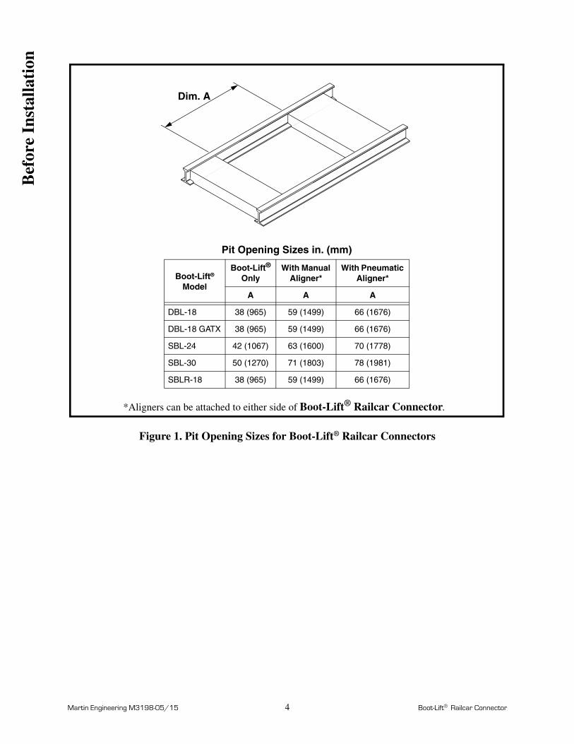
6. Construct pit opening for Railcar Connector as shown in Figure 1.
IMPORTANTMinimum area 1-in. (25-mm) deep by 5-in. (127-mm) long is required beneath rails to fasten aligner brackets to rails.
7. If using an aligner, make sure area beneath rail has minimum clearance of 1 in. (25 mm) in depth by 5 in. (127 mm) in length to connect aligner.
Bef
ore
Inst
alla
tion
Martin Engineering M3198-05/15 4 Boot-Lift Railcar Connector
Figure 1. Pit Opening Sizes for Boot-Lift® Railcar Connectors
Dim. A
Pit Opening Sizes in. (mm)
Boot-Lift® Model
Boot-Lift® Only
With Manual Aligner*
With Pneumatic Aligner*
A A A
DBL-18 38 (965) 59 (1499) 66 (1676)
DBL-18 GATX 38 (965) 59 (1499) 66 (1676)
SBL-24 42 (1067) 63 (1600) 70 (1778)
SBL-30 50 (1270) 71 (1803) 78 (1981)
SBLR-18 38 (965) 59 (1499) 66 (1676)
*Aligners can be attached to either side of Boot-Lift® Railcar Connector.
Bef
ore
Inst
alla
tion
Martin Engineering M3198-05/15 5 Boot-Lift Railcar Connector
Installing Boot-Lift® Railcar Connector
IMPORTANTRead entire section before beginning work.
1. To install the Boot-Lift® Railcar Connector, follow the procedures corresponding to the following steps:
a. Install boot onto Railcar Connector funnel.
b. Install control console and connect hoses.
c. Position Railcar Connector on rails.
d. Connect air lines.
e. Fill console tank.
f. Install boot onto conveyor chute.
g. Install manual or pneumatic aligner, if using.
h. Position sponge seals on Railcar Connector, if using.
2. To operate the Boot-Lift® Railcar Connector, see the “Operating Boot-Lift® Railcar Connector” section.
Installing boot onto Railcar Connector funnel
WARNING!
Be careful not to pinch your fingers in the Railcar Connector assembly.
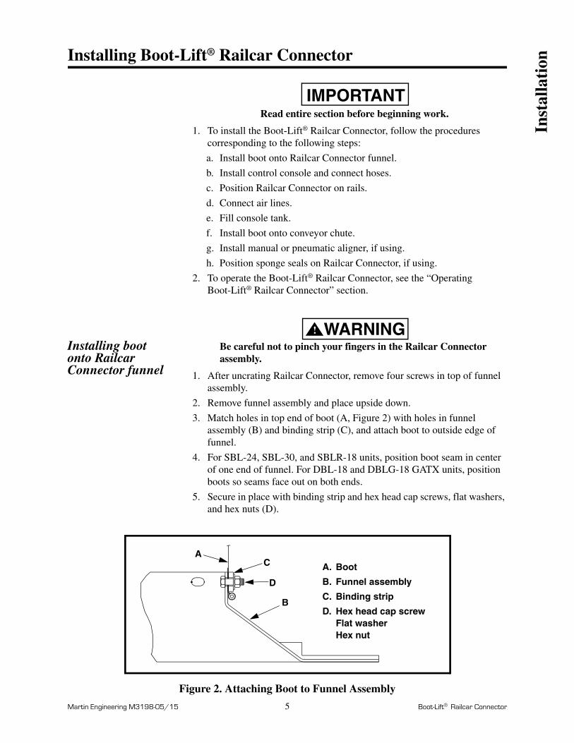
1. After uncrating Railcar Connector, remove four screws in top of funnel assembly.
2. Remove funnel assembly and place upside down.
3. Match holes in top end of boot (A, Figure 2) with holes in funnel assembly (B) and binding strip (C), and attach boot to outside edge of funnel.
4. For SBL-24, SBL-30, and SBLR-18 units, position boot seam in center of one end of funnel. For DBL-18 and DBLG-18 GATX units, position boots so seams face out on both ends.
5. Secure in place with binding strip and hex head cap screws, flat washers, and hex nuts (D).
Figure 2. Attaching Boot to Funnel Assembly
A
B
C
D
A.
B.
C.
D.
Boot
Funnel assembly
Binding strip
Hex head cap screwFlat washerHex nut
Inst
alla
tion

Martin Engineering M3198-05/15 6 Boot-Lift Railcar Connector
Installing control console and hoses
IMPORTANTMount control console so operator has a clear line of sight to Boot-Lift® Railcar Connector.
1. Mount control console using best available field resources. Ensure console operator has a clear line of sight to Boot-Lift® Railcar Connector.
2. Install two 90° street elbows into each SBL-24, SBL-30, and SBLR-18 lift cylinder (see Figure 3).
3. Connect hoses to lift cylinders and control console as shown in Figure 3. Route hoses under tracks. Make sure hoses are not pinched or kinked.
Figure 3. Hose Connections for Models SBL-24, SBL-30, and SBLR-18
1/4” x 15’ hose
1/4” x 4’ hose
1/2” x 15’ hose
1/2” x 4’ hose
1/2” tee
1/4” tee
(Not to scale)
Lift valve
Lift valve hoseconnections
to ControlConsole
air
exhaust
tocylinderinlet
Elbows
Supplied air80 to 110 psi
(5.5 to 7.6 bar)
Lock Valve
Inst
alla
tion

Martin Engineering M3198-05/15 7 Boot-Lift Railcar Connector
4. Connect hoses to DBL-18 and DBLG-18 GATX spread cylinders, lift cylinders, and control console as shown in Figure 4. Route hoses under tracks. Make sure hoses are not pinched or kinked.
Figure 4. Hose Connections for Models DBL-18 and DBLG-18 GATX
(Not to scale)
Spread Cylinders
Control Console
Spread valve
Lift valve
Speed control
Lift Cylinders
valve
Lock ValveFlow
Bleed Screw
Air lines
Hydraulic line
Supplied air
A.
B.
C.
D.1/4” x 4’ hose
1/4” x 15’ hose
1/2” x 4’ hose
1/2” x 15’ hose
E.
F.
1/4” tee
1/2” tee
AA
B
C
D
E
F
A
E
B
air inlet
air inlet
to front of
to back of
exhaust
to lift
to ControlConsole
cylinders
exhaust
cylinders
cylinders
E
80 to 110 psi(5.5 to 7.6 bar)
Inst
alla
tion

Martin Engineering M3198-05/15 8 Boot-Lift Railcar Connector
Positioning Railcar Connector on rails
1. See Figure 5. With the hydraulic street elbow fitting toward operator’s side of track, slip one end of Railcar Connector against rail web.
2. Drop other end in place so that Railcar Connector rests on top of rail flanges between the two rails.
Figure 5. Positioning Railcar Connector on Rails
Connecting air lines
IMPORTANTOne cfm (0.4 L/sec.) and 90 psi (6.21 bar) is required to operate the Railcar Connector. Martin Engineering recommends using an air filter on the air line (available from Martin Engineering).
See Figures 3 and 4. Run a filtered, 1/4-in. air line (supplied by the customer) from the air supply to the regulator on the control console.
Filling console tank
NOTEAutomatic transmission fluid can be replaced with BP (British Petroleum) Enerpar M for food grade applications, or BP Bartran HV for cold-temperature applications. (32°F [0°C] and below).
1. See Figure 4. Fill console tank with automatic transmission fluid through the 1/2-in. filler plug in top of tank. Replace plug.
2. With lock valve in UP position and air regulator set at approximately 10 psi (0.7 bar), open bleed screw one half turn on one of the cylinders.
3. Slowly open lock valve and bleed all air out of system.
4. Tighten bleed screw when oil begins to seep out around it.
5. Repeat procedure for other cylinder.
6. With unit in DOWN position, refill tank to 5 in. (127 mm) from top. Use dipstick to measure. Replace plug. (Approximately 10 quarts [9.5 liters] of oil are required.)
7. Drain moisture from bottom of console once a month.
8. Return regulator to 80-110 psi for normal operation.
Inst
alla
tion

Martin Engineering M3198-05/15 9 Boot-Lift Railcar Connector
Installing boot onto conveyor chute
IMPORTANTMake sure bleed screw is completely closed before operating control console. If bleed screw is not completely closed, fluid will leak out and control console will not operate.
1. See Figure 4. With all fittings and hoses in place, open lock valve and move lift valve to the UP position. (Unit will rise.)
2. Close lock valve to lock unit in UP position and ensure enough room to install boot to conveyor system.
IMPORTANTA minimum of 3 in. (76 mm) is required between the lower flange of the track and the top of your conveyor opening for the boot to collapse without damage.
3. Install boots inside conveyor opening.
4. If necessary, bolt boot to conveyor with retaining straps (supplied by customer).
5. If necessary, use an adapter frame to make boot fit. (Martin Engineering can manufacture adapter frame from customer-supplied dimensions.)
Installing optional manual aligner
IMPORTANTAn area 1-in. (25-mm) deep by 5-in. (127-mm) long is required beneath rails to fasten aligner brackets to rails (see “Before Installing Boot-Lift® Railcar Connector”).
1. See Figure 6. Install manual aligner on the most accessible side of the Railcar Connector.
2. Slip finger clamps (A) over frame rail (B) on Railcar Connector.
3. Adjust aligner frame so it is in center of its travel, then clamp aligner brackets (C) to rails.
Inst
alla
tion

Martin Engineering M3198-05/15 10 Boot-Lift Railcar Connector
Figure 6. Installing Manual Aligner
CAUTION!
Do not move railcar when adjusting handle is in aligner socket. If railcar is allowed to run over it, handle may be thrown from unit.
4. To operate aligner, slip adjusting bar (D) into socket on aligner and move adjusting bar parallel to tracks.
Installing optional pneumatic aligner
Figure 7. Installing Pneumatic Aligner
A
B
C
D
A.
B.
C.
D.
Finger clamps
A
Frame rail
Aligner bracket
Adjusting bar
A
B
C
D
E
F
A.
B.
C.
D.
E.
F.
Angle guide
Clevis pin
Cylinder
Guide clip (4)
Cylinder mount channel
Clamp (2)
Inst
alla
tion

Martin Engineering M3198-05/15 11 Boot-Lift Railcar Connector
1. See Figure 7. Place pneumatic aligner between rail tracks with aligner angle guide (A) next to Railcar Connector.
2. Remove clevis pin (B) to separate angle guide from cylinder (C).
3. Slip angle guide clips (D) under frame rail on Railcar Connector.
4. Locate cylinder mount channel (E, Figure 7) so its face is 4-7/8 in. (124 mm) from face of angle guide. Slip clamp (F) on each end of cylinder mount channel under rail track.
5. Pull out cylinder rod and secure to angle guide with clevis pin.
6. Make air line connections to valve assembly as shown in the schematic in Figure 8.
Figure 8. Pneumatic Aligner Schematic
7. Test operation of pneumatic aligner by applying 10 psi (0.7 bar). If necessary, adjust air pressure up until a safe operating pressure is reached.
Positioning seals 1. Lay sponge seals on Railcar Connector funnel assembly or on adapter sheet.
2. After railcar is in place over unit, adjust air regulating valve so that sponge seals are compressed by 50 percent.
air flow
A,B
C
B,D B,D
DE
B
F
CA,B C
4 ft(1.25 m)
15 ft(4.50 m)
15 ft(4.50 m)
A.
B.
C.
D.
E.
F.1/2 NPT x 1/4 NPT reducer
1/4 NPT x 3/8 fitting
3/8 grey hose
3/8 NPT x 1/4 NPT reducer
1/4 NPT x 3.00 nipple
3/8 NPT regulator1/4 NPT air gauge (AG2)
30 psi max.@ 1 cfm
) (
G. 1/4 x 1-1/2 SCH 40 nipple
HG
H. Valve 1/4 Flow Control
Inst
alla
tion

Martin Engineering M3198-05/15 12 Boot-Lift Railcar Connector
Operating Boot-Lift® Railcar Connector
WARNING!
Hoses contain hydraulic fluid under pressure. If punctured, oil can penetrate skin and cause injection poisoning. If oil penetrates skin, see a doctor trained in fluid injection poisoning immediately.
IMPORTANTOne cfm (0.4 L/sec.) and 90 psi (6.21 bar) is required to operate the Railcar Connector.
Operating SBL Railcar Connectors
1. To raise unit, do the following:
a. Place lift valve in UP position and control upward speed by using control handle on lock valve.
b. Keep lock valve partially open at all times while unloading to allow unit to raise with the car as the weight of its contents decreases.
2. To lower unit, place lift valve in DOWN position with lock valve open.
3. Padlock control console when not in use to prevent tampering.
Operating DBL Railcar Connectors
1. See Figure 4. To raise unit, do the following:
a. Place lift valve in UP position. Control upward movements with lock valve.
b. Raise funnels only enough to clear rails. Hold in this position by closing lock valve.
c. Place handle of spread valve in UP position spreading funnels outward to stops. (Stops should be set to allow funnels to move outward approximately 5 in. [127 mm] each to match width of car pockets.)
d. Keep lock valve partially open while unloading to allow Railcar Connector to raise with car as the weight of its contents decreases. (With lock valve partially open, it will serve as a hydraulic shock retarder to hold unit sealed against a sudden surge of material causing pressure on the unit.)
CAUTION!
Do not move railcar with Railcar Connector in the UP position. Unit will be severely damaged.
2. See Figure 4. To lower unit, do the following:
a. Open lock valve enough to begin lowering unit.
b. When funnels clear car, place spread valve in DOWN position to retract funnels, then continue lowering unit slowly to prevent damage to the boots.
c. Allow Railcar Connector to settle completely down between rails before attempting to move car.
Ope
rati
on
Martin Engineering M3198-05/15 13 Boot-Lift Railcar Connector
Maintenance
Monthly maintenance
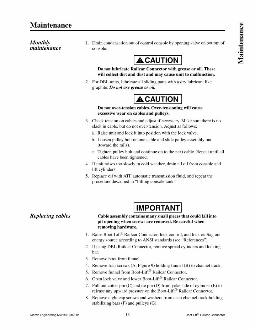
1. Drain condensation out of control console by opening valve on bottom of console.
CAUTION!
Do not lubricate Railcar Connector with grease or oil. These will collect dirt and dust and may cause unit to malfunction.
2. For DBL units, lubricate all sliding parts with a dry lubricant like graphite. Do not use grease or oil.
CAUTION!
Do not over-tension cables. Over-tensioning will cause excessive wear on cables and pulleys.
3. Check tension on cables and adjust if necessary. Make sure there is no slack in cable, but do not over-tension. Adjust as follows:
a. Raise unit and lock it into position with the lock valve.
b. Loosen pulley bolt on one cable and slide pulley assembly out (toward the rails).
c. Tighten pulley bolt and continue on to the next cable. Repeat until all cables have been tightened.
4. If unit raises too slowly in cold weather, drain all oil from console and lift cylinders.
5. Replace oil with ATF automatic transmission fluid, and repeat the procedure described in “Filling console tank.”
Replacing cablesIMPORTANT
Cable assembly contains many small pieces that could fall into pit opening when screws are removed. Be careful when removing hardware.
1. Raise Boot-Lift® Railcar Connector, lock control, and lock out/tag out energy source according to ANSI standards (see “References”).
2. If using DBL Railcar Connector, remove spread cylinders and locking bar.
3. Remove boot from funnel.
4. Remove four screws (A, Figure 9) holding funnel (B) to channel track.
5. Remove funnel from Boot-Lift® Railcar Connector.
6. Open lock valve and lower Boot-Lift® Railcar Connector.
7. Pull out cotter pin (C) and tie pin (D) from yoke side of cylinder (E) to release any upward pressure on the Boot-Lift® Railcar Connector.
8. Remove eight cap screws and washers from each channel track holding stabilizing bars (F) and pulleys (G).
Mai
nten
ance

Martin Engineering M3198-05/15 14 Boot-Lift Railcar Connector
9. Push stabilizing bars down out of the way and remove wheels (H).
10. Lift the channel track (J) so it will clear edge of pit and slide off frame.
11. Remove wheels and bushings on inside lift arms.
12. Remove old cable assembly and clean any rust or dirt accumulating on parts. Make sure all wheels spin freely and there is no wear on the bushings or wheels.
13. Install new cable assembly (K), making sure it hangs like a figure eight over the wheels.
Figure 9. Replacing Cable Assembly
14. Install wheels and bushings.
15. Pull the lift arms up one at a time and slide channel track back on, making sure slots are toward the inside.
16. Loop each side of cable around pulley and insert into channel track. Make sure flat parts of cable slides fit into slots on inside of channel track. Secure with hex head cap screws and washers. DO NOT tighten until second cable assembly has been installed.
17. Re-attach stabilizing bars and secure with removed hardware.
18. Repeat steps 7 through 17 for opposite side cable assembly.
19. Slide cable hardware toward outside of slot and tighten. Tap wrench with mallet while tightening to stretch cable tightly.
20. Repeat steps 18 and 19 for remaining cable slides.
21. Re-assemble remaining components in the opposite order they were removed.
B A
C
D
KHG
J
F
E
A.B.C.D.E.
Hex head cap screw (4)FunnelCotter pin (4)Tie pin (4)Lift cylinder (2)
F. G.
H.J.K.
Stabilizing bar (4)Pulley (4)Wheel (4)Channel track (2)Cable assembly (2)
Mai
nten
ance

Notes

Martin Engineering M3198-05/15 16 Boot-Lift Railcar Connector
Part Numbers
This section provides product names and corresponding part numbers for Boot-Lift® Railcar Connectors and related equipment. Please reference part numbers when ordering parts.
NOTEAll boots are custom-made for your application. To order, complete the Application Data Sheet on the last two pages of this manual. Call Martin Engineering or a representative for more information.
Boot-Lift® Railcar Connectors
Boot-Lift® Adapter Sheets
MODEL # SBL-24 SBL-30 SBLR-18 DBL-18PAINT COLOR S: Orange (Standard) F: White (Food Grade) C: Gray (Corrosion Resistant)
FUNNEL TYPE Ø: No Funnel 1: Painted Funnel 2: Stainless Funnel
CONTROL CONSOLE Ø: No Controls 1: Air-Over-Hydraulic Controls
LIFT CYLINDERS Ø: No Lift Cyliners 1: Hydraulic Lift Cylinders
SPREAD CYLINDERS
Ø: No Spread Cylinders 1: Standard Hardware 2: Stainless Hardware
XXXXX X X X X X
Paint Color Funnel Type Cylinder Controls Lift Cylinders Spread Cylinders
(DBL-18 only)
P/N Example: SBL-30S111 Model SBL-30 with orange paint, painted funnel, air-over-hydraulic controls, and hydraulic lift cylinders
MODEL # SBL-24AS SBL-30AS DBL-18AS
MATERIAL TYPE W: Wood H: High Density Polyethylene
FOAM SEAL Ø: No Wrap W: White Hypalon Wrapped
XXXXX XXXX X X
Opening Size Material Type Foam Wrap
P/N Example: SBL-30AS2430W0 Fits Boot-Lift® model SBL-30, 24 x 30 opening, wood with no wrap on the foam seal.
Par
t N
umbe
rs

Martin Engineering M3198-05/15 17 Boot-Lift Railcar Connector
Boot-Lift® Control Consoles
Boot-Lift® DBL-18 Control Console: P/N 16953. See Figure 14.
Boot-Lift® Control Console Assembly: P/N 17256. See Figure 15.
Boot-Lift® Aligners
Manual Aligner: P/N 17326.
Pneumatic Aligner: P/N 34140. See Figure 16.
Miscellaneous
*Use with transition adapter sheet, P/N 20264-XX.
Boot-Lift® Assembly Part Numbers
Accessories SBL-24 SBL-30 DBL-18 DBLG-18 SBLR-18
Sponge Seal 17203 1720316681
16681-W (wrapped)18311 (box of six)
1981619816-W (wrapped)20518 (box of six)
Urethane Seal
36732-15
Lift Cylinder Cover 18335 18335 18335 18335 18335
Lift Cylinder Repair Kit
27960 27960 27960 27960 27960
Funnel Cover 19544 34884-CA 18420 18420 —
Transition Funnel — — 17272* 17272* —
Spread Cylinder Cover
— — 18331 18331 —
Spread Cylinder Repair Kit
— — 20714 20714 —
Boot-Lift® Assembly Replacement/ Repair Part Numbers
SBL-24 SBL-30 DBL-18 DBLG-18
Funnel - Standard 17024 34884-F 17029/17100 19739/18301
Funnel - Stainless Steel 17024-SS 34884-FSS 17029-SS/17100-SS SP02565-L/SP02565-R
Binding Straps17260-04/17260-03
17260-12/17260-03
17260-01/17260-02 —
Foam Seal 17203 17203 16681 19816
Cable Assembly 16974 16974 16974 16974
Pulley 17022 17022 17022 17022
Pulley Slide/ Bushing 17023 17023 17023 17023
Lift Cylinder 16963 16963 16963 16963
Lift Cylinder Rebuild Kit 27960 27960 27960 27960
Spread Cylinder — — 17033 38342S-DBLG
Par
t N
umbe
rs

Martin Engineering M3198-05/15 18 Boot-Lift Railcar Connector
Figure 10. Boot-Lift SBL Assembly, P/N SBL-XXXXX
*Order boot separately. Complete an Application Data Sheet, Form No. L3729 (included at the end of this manual), and send to Martin Engineering or a representative.
Table I. Boot-Lift SBL Assembly Part Numbers
Item Description Part No. Qty
1 Adjustable Frame Assembly Table I 1
2 Funnel Assembly Table I 1
3 (NS) Control Assembly Table I 1
4 Hydraulic Lift Cylinder Assembly Table I 1
AssemblyP/N
Item 1P/N
Components Paint Color
AssemblyP/N
Item 2P/N Funnel Type
SBL-24SXXX 38338S-SBL Martin® Orange SBL-24S1XX 38339S-SBL24 Painted
SBL-30SXXX 38338X-SBL-30 Martin® Orange SBL-24F2XX 38339X-SBL24 Stainless Steel
SBL-24FXXX 38338X-SBL Epoxy White SBL-24C2XX 38339X-SBL24 Stainless Steel
SBL-30FXXX 38338S-SBL-30 Epoxy White SBL-30S1XX 38339S-SBL30 Painted
SBL-24CXXX 38338X-SBL Steel-It Gray SBL-30F2XX 38339X-SBL30 Stainless Steel
SBL-30CXXX 38338X-SBL-30 Steel-It Gray SBL-30C2XX 38339X-SBL30 Stainless Steel
AssemblyP/N
Item 3P/N
Item 4P/N
Components Paint Color
SBL-XXSX11 38340S-SBL 38341S-1 Martin® Orange
SBL-XXFX11 38340X-SBL 38341X-1 Epoxy White
SBL-XXCX11 38340X-SBL 38341X-1 Steel-It Gray
2
1
4
Par
t N
umbe
rs
Martin Engineering M3198-05/15 19 Boot-Lift Railcar Connector
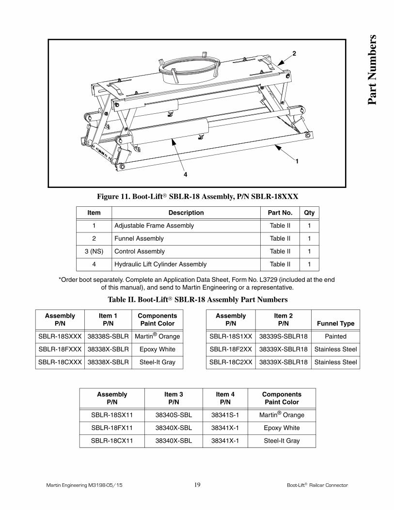
Figure 11. Boot-Lift SBLR-18 Assembly, P/N SBLR-18XXX
*Order boot separately. Complete an Application Data Sheet, Form No. L3729 (included at the end of this manual), and send to Martin Engineering or a representative.
Table II. Boot-Lift SBLR-18 Assembly Part Numbers
Item Description Part No. Qty
1 Adjustable Frame Assembly Table II 1
2 Funnel Assembly Table II 1
3 (NS) Control Assembly Table II 1
4 Hydraulic Lift Cylinder Assembly Table II 1
AssemblyP/N
Item 1P/N
Components Paint Color
AssemblyP/N
Item 2P/N Funnel Type
SBLR-18SXXX 38338S-SBLR Martin® Orange SBLR-18S1XX 38339S-SBLR18 Painted
SBLR-18FXXX 38338X-SBLR Epoxy White SBLR-18F2XX 38339X-SBLR18 Stainless Steel
SBLR-18CXXX 38338X-SBLR Steel-It Gray SBLR-18C2XX 38339X-SBLR18 Stainless Steel
AssemblyP/N
Item 3P/N
Item 4P/N
Components Paint Color
SBLR-18SX11 38340S-SBL 38341S-1 Martin® Orange
SBLR-18FX11 38340X-SBL 38341X-1 Epoxy White
SBLR-18CX11 38340X-SBL 38341X-1 Steel-It Gray
2
1
4
Par
t N
umbe
rs
Martin Engineering M3198-05/15 20 Boot-Lift Railcar Connector
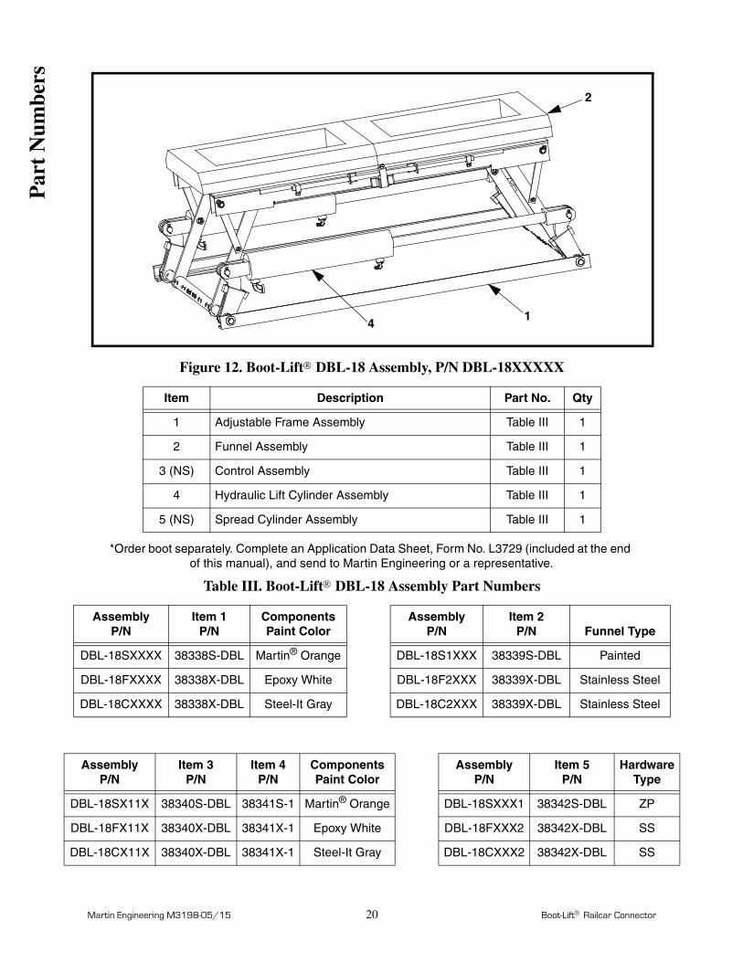
Figure 12. Boot-Lift DBL-18 Assembly, P/N DBL-18XXXXX
*Order boot separately. Complete an Application Data Sheet, Form No. L3729 (included at the end of this manual), and send to Martin Engineering or a representative.
Table III. Boot-Lift DBL-18 Assembly Part Numbers
Item Description Part No. Qty
1 Adjustable Frame Assembly Table III 1
2 Funnel Assembly Table III 1
3 (NS) Control Assembly Table III 1
4 Hydraulic Lift Cylinder Assembly Table III 1
5 (NS) Spread Cylinder Assembly Table III 1
AssemblyP/N
Item 1P/N
Components Paint Color
AssemblyP/N
Item 2P/N Funnel Type
DBL-18SXXXX 38338S-DBL Martin® Orange DBL-18S1XXX 38339S-DBL Painted
DBL-18FXXXX 38338X-DBL Epoxy White DBL-18F2XXX 38339X-DBL Stainless Steel
DBL-18CXXXX 38338X-DBL Steel-It Gray DBL-18C2XXX 38339X-DBL Stainless Steel
AssemblyP/N
Item 3P/N
Item 4P/N
Components Paint Color
AssemblyP/N
Item 5P/N
HardwareType
DBL-18SX11X 38340S-DBL 38341S-1 Martin® Orange DBL-18SXXX1 38342S-DBL ZP
DBL-18FX11X 38340X-DBL 38341X-1 Epoxy White DBL-18FXXX2 38342X-DBL SS
DBL-18CX11X 38340X-DBL 38341X-1 Steel-It Gray DBL-18CXXX2 38342X-DBL SS
2
14
Par
t N
umbe
rs
Martin Engineering M3198-05/15 21 Boot-Lift Railcar Connector
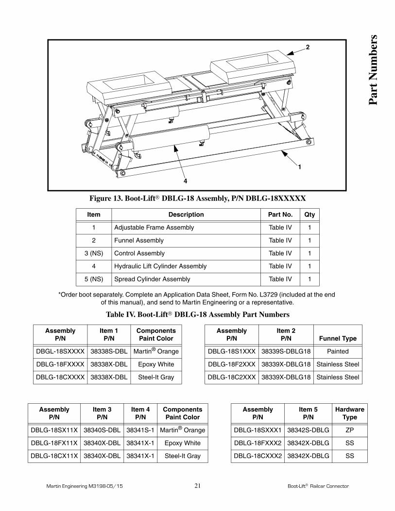
Figure 13. Boot-Lift DBLG-18 Assembly, P/N DBLG-18XXXXX
*Order boot separately. Complete an Application Data Sheet, Form No. L3729 (included at the end of this manual), and send to Martin Engineering or a representative.
Table IV. Boot-Lift DBLG-18 Assembly Part Numbers
Item Description Part No. Qty
1 Adjustable Frame Assembly Table IV 1
2 Funnel Assembly Table IV 1
3 (NS) Control Assembly Table IV 1
4 Hydraulic Lift Cylinder Assembly Table IV 1
5 (NS) Spread Cylinder Assembly Table IV 1
AssemblyP/N
Item 1P/N
Components Paint Color
AssemblyP/N
Item 2P/N Funnel Type
DBGL-18SXXXX 38338S-DBL Martin® Orange DBLG-18S1XXX 38339S-DBLG18 Painted
DBLG-18FXXXX 38338X-DBL Epoxy White DBLG-18F2XXX 38339X-DBLG18 Stainless Steel
DBLG-18CXXXX 38338X-DBL Steel-It Gray DBLG-18C2XXX 38339X-DBLG18 Stainless Steel
AssemblyP/N
Item 3P/N
Item 4P/N
Components Paint Color
AssemblyP/N
Item 5P/N
HardwareType
DBLG-18SX11X 38340S-DBL 38341S-1 Martin® Orange DBLG-18SXXX1 38342S-DBLG ZP
DBLG-18FX11X 38340X-DBL 38341X-1 Epoxy White DBLG-18FXXX2 38342X-DBLG SS
DBLG-18CX11X 38340X-DBL 38341X-1 Steel-It Gray DBLG-18CXXX2 38342X-DBLG SS
2
1
4
Par
t N
umbe
rs

Martin Engineering M3198-05/15 22 Boot-Lift Railcar Connector
Figure 14. Boot-Lift DBL-18 Control Console, P/N 38340X-DBL**
Item Description Part No. Qty
1 Screw RHM 1/4-20NC x .75 17325 4
2 Nut Hex 1/4-20NC 11769 4
3 Control Tank Weldment 23897 1
4 Elbow 90° 15875 1
5 Bushing Shoulder 18308 1
6 Handle Valve 16989 1
7 Valve Ball w/o Handle 26027 1
8 Drain Cock 17217 1
9 Hose Lift 1/2 x 15 ft 17234 1
10 Valve Control 17218 2
11 Pipe Nipple 17219 2
12 Valve Flow Control 20547 1
13 Hose Raise 1/4 x 15 ft 17223 3
14 Air Gauge AG2 14725 1
15 Elbow 90° 17238 1
16 Bushing Reducing 13259 1
12
3
4 5
6
78 9
10 11 12 13
14
15161718
19
20
21
14 - 18
19
13
13
1112
13
19
22
Par
t N
umbe
rs

Martin Engineering M3198-05/15 23 Boot-Lift Railcar Connector
Figure 14. Boot-Lift DBL-18 Control Console, P/N 38340X-DBL**
NS = Not Shown* Refer to Figure 4.** X indicates: standard components (S) or corrosion resistant components (X).
17 Regulator BR4 14728 1
18 Street Tee 17220 1
19 Hose Raise 1/4 x 7.00 17227 1
20 Plug Pipe 12204 1
21 Hose Assembly Spread 36412 1
22 Elbow Male NPSM Swivel 1/4-18 NPT 36413 1
*NS Hose Lift 1/2 x 4 ft 27802-48 2
*NS Tee 1/2 17241 1
*NS Hose Cylinder 1/4 x 4 ft 17226 6
*NS Tee Female 1/4 17240 3
Appendix A Label Boot-Lift Connector Air Pressure 22213 1
Appendix A Label Boot-Lift Connector Warning 33378 1
Item Description Part No. Qty
Par
t N
umbe
rs

Martin Engineering M3198-05/15 24 Boot-Lift Railcar Connector
Figure 15. Boot-Lift Control Console Assembly, P/N 38340X-SBL
Item Description Part No. Qty
1 Screw HHC 1/4-20NC x .75 11852 2
2 Nut Hex 1/4-20NC 11769 2
3 Control Tank Weldment 23897 1
4 Adapter Union 90° 3/4NPT 15875 1
5 Nipple Hex Close 3/4NPT 18308 1
6 Valve Ball w/o Handle 3/4NPT 26027 1
7 Drain Cock 1/4NPT 17217 1
8 Hose Lift 1/2 x 15 ft 17234 1
9 Valve Handle 16989 1
10 Hose Raise 1/4 x 15 ft 17223 1
11 Regulator 1/4NPT 14728 1
12 Hose Raise 1/4 x 7 ft 17227 1
13 4-Way Control Valve 17218 1
14 Plug Pipe HHS 1/2NPT 12204 1
15 Air Gauge AG2 1/8NPT 14725 1
12
3
4 5
6
7 8
9
10
1112
13
14 15
16171812
10
Par
t N
umbe
rs

Martin Engineering M3198-05/15 25 Boot-Lift Railcar Connector
Figure 15. Boot-Lift Control Console Assembly, P/N 38340X-SBL**
NS = Not Shown* Refer to Figure 3.** X indicates: standard components (S) or corrosion resistant components (X).
16 Elbow JIC 90° 1/8NPT x 7/16 17238 1
17 Bushing Reducing 1/8NPT x 1/4NPT 13259 1
18 Nipple Pipe 1/4NPT x 3.00 17255 1
*NS Hose Lift 1/2 x 4 ft 27802-48 2
*NS Tee 1/2 17241 2
*NS Hose Cylinder 1/4 x 4 ft 17226 2
*NS Tee Female 1/4 17240 2
Appendix A Label Boot-Lift Connector Air Pressure 22213 1
Appendix A Label Boot-Lift Connector Warning 33378 1
Item Description Part No. Qty
Par
t N
umbe
rs

Martin Engineering M3198-05/15 26 Boot-Lift Railcar Connector
Figure 16. Pneumatic Aligner Assembly, P/N 34140-XX
Item Description Part No. Qty
1 Channel Cylinder Mount 34141 1
2 Pin Clevis 32180-01 1
3 Cotter Hairpin 32999 1
4 Clevis Piston Rod 32131 1
5 Cylinder Pneumatic 8.00 Stroke 34161 1
6 Nut 3/4-16NF Jam 32242 1
7 Angle Guide Weldment 34142 1
8 Guide Clip Weldment 34158 4
9 Washer Compression SS 1/2 24310 2
10 Nut Hex SS 1/2-13NC 17151 2
11 Clamp Aligner 17307 2
12 Screw Hex Head Cap 1/2-13NC x 1.50 11763 4
13 Nut Hex 1/2-13NC 11771 4
14 Washer Compression 1/2 11750 4
15 Screw Hex Head Cap 3/8-24NF x 1.00 34157 4
air flow
to ControlConsole
1
23
4
5
6
7
8
91011
121314 15
161718
19
20
212223
24
25
1820 18
20
191819 1917
18
15 ft(4.50 m)
4 ft(1.25 m)
15 ft(4.50 m) 1 ft (.33 m)
26
27) (
Par
t N
umbe
rs

Martin Engineering M3198-05/15 27 Boot-Lift Railcar Connector
*Use part number 34140 to order aligner with 35 ft (11 m) of hose.
16 Washer Compression 3/8 28565 4
17 Reducer 1/2NPT x 1/4NPT 22465 2
18 Fitting Hose 1/4NPT x 3/8 17224 7
19 Hose Grey 3/8 21241 35 or 52 ft*
20 Reducer 3/8NPT x 1/4NPT SPO2781-04 3
21 Nipple 1/4NPT x 3.00 17255 1
22 3/8NPT Regulator 14741 1
23 Gauge Air AG2 1/4NPT 34242 1
24 Tee Union 1/4NPT 17240 1
25 Fitting Hose 7/16 JIC x 3/8 17222 1
26 Nipple 1/4 x 1-1/2 SCH 40 17219 1
27 Valve 1/4 Flow Control 20547 1
NS Hand Valve Assembly M900 1
Appendix A Label Pinch Point Warning 30528 1
Item Description Part No. Qty
Par
t N
umbe
rs


Martin Engineering M3198-05/15 A-1 Boot-Lift Railcar Connector
Boot-Lift Air Pressure Fluid Level Label, P/N 22213
App
endi
x A
AIR PRESSURE:110 lbs air pressurefor operation.
FLUID LEVEL:should never be
Do not overfill.
higher than 5 in.from the top.
Must have 80 to
Transmission fluid
IMPORTANT
LABEL P/N 22213
Pinch Point Warning Label, P/N 30528
Appendix ABoot-Lift Railcar Connector Labels
Pinch point!
Label P/N 30528
!WARNING!
MUCHO CUIDADO!
¡Usted se puedepellizcar!

Martin Engineering M3198-05/15 A-2 Boot-Lift Railcar Connector
App
endi
x A
WARNING
Label P/N 33378
!
Explosion hazard.Do not apply morethan 125 lb. of air
Serious injury ordeath could result.
pressure to unit.
Boot-Lift Air Pressure Warning Label, P/N 33378
MUCHOWARNING!Hydraulic fluid underpressure. Oil can pene-trate skin and causeinjection poisoning. Ifoil penetrates skin, seea doctor trained in fluidinjection poisoningimmediately.
CUIDADO!
Fluido hidraulico bajopresión. Aceite puedepenetrar en la piel yresultar venenoso. Siel aceite penetra en lapiel, vea a un medicoespecializado eninyección de fluido.
Label P/N 35237
Hydraulic Fluid Warning Label, P/N 35237

Martin Engineering M3198-05/15 B-1 Boot-Lift Railcar Connector
Appendix BBoot-Lift Railcar Connector Dimensions
Model AB
C DExtended Retracted
SBL-24 57 (1448) 18.48 (469) 4.48 (114) 40.38 (1026) 54 (1372)
SBL-30 57 (1448) 18.48 (469) 4.48 (114) 48.38 (1229) 54 (1372)
SBLR-18 57 (1448) 18.92 (481) 6.02 (153) 36.38 (924) 51.5 (1308)
DBL-18 57 (1448) 15.17 (385) 5.34 (136) 36.38 (924)54 (1372) closed69 (1753) open
DBLG-18 GATX 57 (1448) 15.17 (385) 5.70 (145) 36.38 (924)54 (1372) closed78.5 (1994) open
Model E F G
SBL-24 29.2 (742) 22 (559) —
SBL-30 37.3 (947) 30 (762) —
SBLR-18 29.2 (742) Ø15 (381) —
DBL-18 19.50 (495) 11.25 (286)27 (686) closed42 (1067) open
DBL-18 GATX 18.00 (457) 9.00 (229)36 (914) closed
58.6 (1488) open
16.5(419)
FE C
G
D
B
A
E CF42 (1067)
D
B
A
CL CL
App
endi
x B

Notes
Form No. L3729-10/12© Martin Engineering Company 2007, 2012
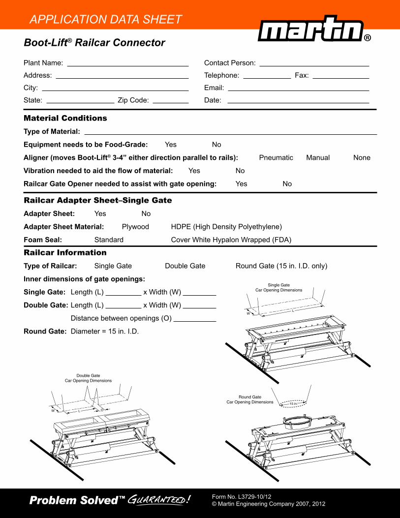
APPLICATION DATA SHEET
Material ConditionsType of Material:
Equipment needs to be Food-Grade: Yes No
Aligner (moves Boot-Lift® 3-4” either direction parallel to rails): Pneumatic Manual None
Vibration needed to aid the flow of material: Yes No
Railcar Gate Opener needed to assist with gate opening: Yes No
Boot-Lift® Railcar Connector
Plant Name:
Address:
City:
State: Zip Code:
Contact Person:
Telephone: Fax:
Email:
Date:
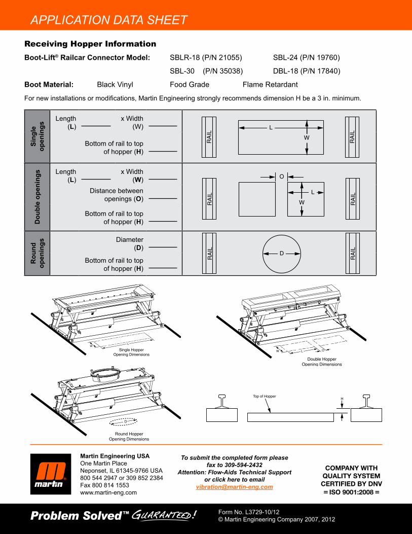
Railcar InformationType of Railcar: Single Gate Double Gate Round Gate (15 in. I.D. only)
Inner dimensions of gate openings:
Single Gate: Length (L) x Width (W)
Double Gate: Length (L) x Width (W)
Distance between openings (O)
Round Gate: Diameter = 15 in. I.D.
Single GateCar Opening Dimensions
LW
Double GateCar Opening Dimensions
LW O
Round GateCar Opening Dimensions 15 in.
Railcar Adapter Sheet–Single GateAdapter Sheet: Yes No
Adapter Sheet Material: Plywood HDPE (High Density Polyethylene)
Foam Seal: Standard Cover White Hypalon Wrapped (FDA)
APPLICATION DATA SHEET
Martin Engineering USAOne Martin PlaceNeponset, IL 61345-9766 USA800 544 2947 or 309 852 2384Fax 800 814 1553www.martin-eng.com
Form No. L3729-10/12© Martin Engineering Company 2007, 2012
To submit the completed form please fax to 309-594-2432
Attention: Flow-Aids Technical Support or click here to email
Single HopperOpening Dimensions
LW
Round HopperOpening Dimensions
D
Double HopperOpening Dimensions
LW O
HTop of Hopper
Sing
le
open
ings
Length (L) x Width
(W)
Bottom of rail to top of hopper (H)
Dou
ble
open
ings Length
(L) x Width (W)
Distance between openings (O)
Bottom of rail to top of hopper (H)
Rou
nd
open
ings Diameter
(D)
Bottom of rail to top of hopper (H)
L
W
L
W
O
D
RA
IL
RA
IL
RA
IL
RA
IL
RA
IL
RA
IL
Receiving Hopper InformationBoot-Lift® Railcar Connector Model: SBLR-18 (P/N 21055) SBL-24 (P/N 19760)
SBL-30 (P/N 35038) DBL-18 (P/N 17840)
Boot Material: Black Vinyl Food Grade Flame Retardant
For new installations or modifications, Martin Engineering strongly recommends dimension H be a 3 in. minimum.

Any product, process, or technology described here may be the subject of intellectual property rights reserved by Martin Engineering Company. Trademarks or service marks designated with the ® symbol are registered with the U.S. Patent and Trademark Office and may be proprietary in one or more countries or regions. Other trademarks and service marks belonging to Martin Engineering Company in the United States and/or other countries or regions may be designated with the “TM” and “SM” symbols. Brands, trademarks, and names of other parties, who may or may not be affiliated with, connected to, or endorsed by Martin Engineering Company, are identified wherever possible. Additional information regarding Martin Engineering Company’s intellectual property can be obtained at www.martin-eng.com/trademarks.

Martin Engineering USAOne Martin PlaceNeponset, IL 61345-9766 USA800 544 2947 or 309 852 2384Fax 800 814 1553www.martin-eng.com
Form No. M3198-05/15 © Martin Engineering Company 1998, 2015


