Download - BRIDGES - IOM3

BRID
GE
S //Sp
anning the g
ap b
etween
construction and m
aterials

BRIDGESSpanning the gap between construction and materials
This folder of information cards and posters forms
the resource for schools joining or renewing their
membership of the Institute of Materials, Minerals
and Mining Schools Affiliate Scheme in the 2009-
2010 academic year. It has been designed as
a reference guide for teachers to link in with
the materials, minerals and mining topics in the
secondary science and technology curricula,
though some sections will also be very relevant to
geology and geography.
This resource has been written by Dr Diane Aston,
Education Co-ordinator and Mr Toby White,
Education Co-ordinator (Minerals and Mining)
from the Institute of Materials, Minerals and Mining.

1 TH
E D
ESIG
NS

History of Brid
ges
http://static.panoramio.com/photos/original/301678.jpg
THE HISTORY OF BRIDGES
Over the centuries bridges have played an enormous and
valuable part in bringing communities together and allowing
easier trade routes to develop. They are portrayed in books
and films as romantic spots where couples meet, or the
middle ground where the final stand-off takes place. Bridges
have evolved from simple logs across streams to massive
and complex engineering structures and every few years
another bridge comes along to beat records and sparks our
imaginations.
The very first bridges were built by Mother Nature and were the
result of falling trees spanning streams or canyons. Man used
these accidental crossings to reach new areas for settlement
and new sources of food. The first man-made bridges copied
this and were made from logs and then later stones. These
very early designs relied on the log or stone being long enough
to cross the gap in a single span. Later designs used simple
crossbeams and support to cross larger gaps.
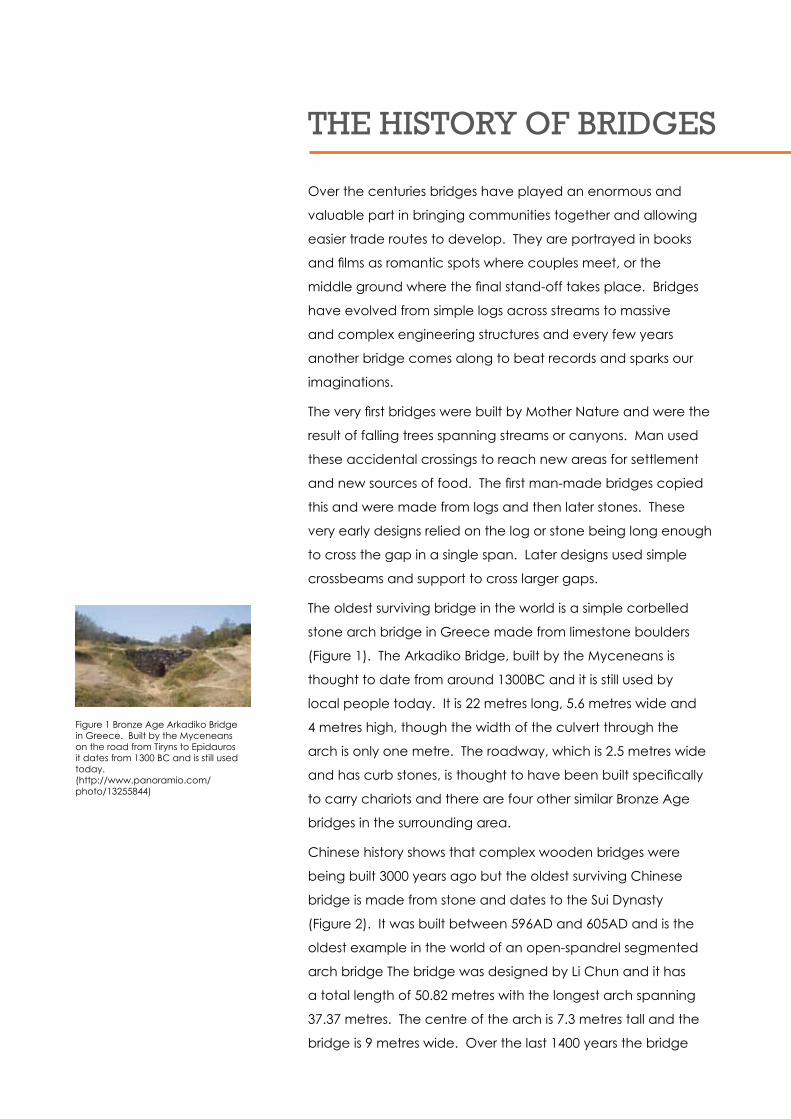
The oldest surviving bridge in the world is a simple corbelled
stone arch bridge in Greece made from limestone boulders
(Figure 1). The Arkadiko Bridge, built by the Myceneans is
thought to date from around 1300BC and it is still used by
local people today. It is 22 metres long, 5.6 metres wide and
4 metres high, though the width of the culvert through the
arch is only one metre. The roadway, which is 2.5 metres wide
and has curb stones, is thought to have been built specifically
to carry chariots and there are four other similar Bronze Age
bridges in the surrounding area.
Chinese history shows that complex wooden bridges were
being built 3000 years ago but the oldest surviving Chinese
bridge is made from stone and dates to the Sui Dynasty
(Figure 2). It was built between 596AD and 605AD and is the
oldest example in the world of an open-spandrel segmented
arch bridge The bridge was designed by Li Chun and it has
a total length of 50.82 metres with the longest arch spanning
37.37 metres. The centre of the arch is 7.3 metres tall and the
bridge is 9 metres wide. Over the last 1400 years the bridge
Figure 1 Bronze Age Arkadiko Bridge in Greece. Built by the Myceneans on the road from Tiryns to Epidauros it dates from 1300 BC and is still used today.(http://www.panoramio.com/photo/13255844)
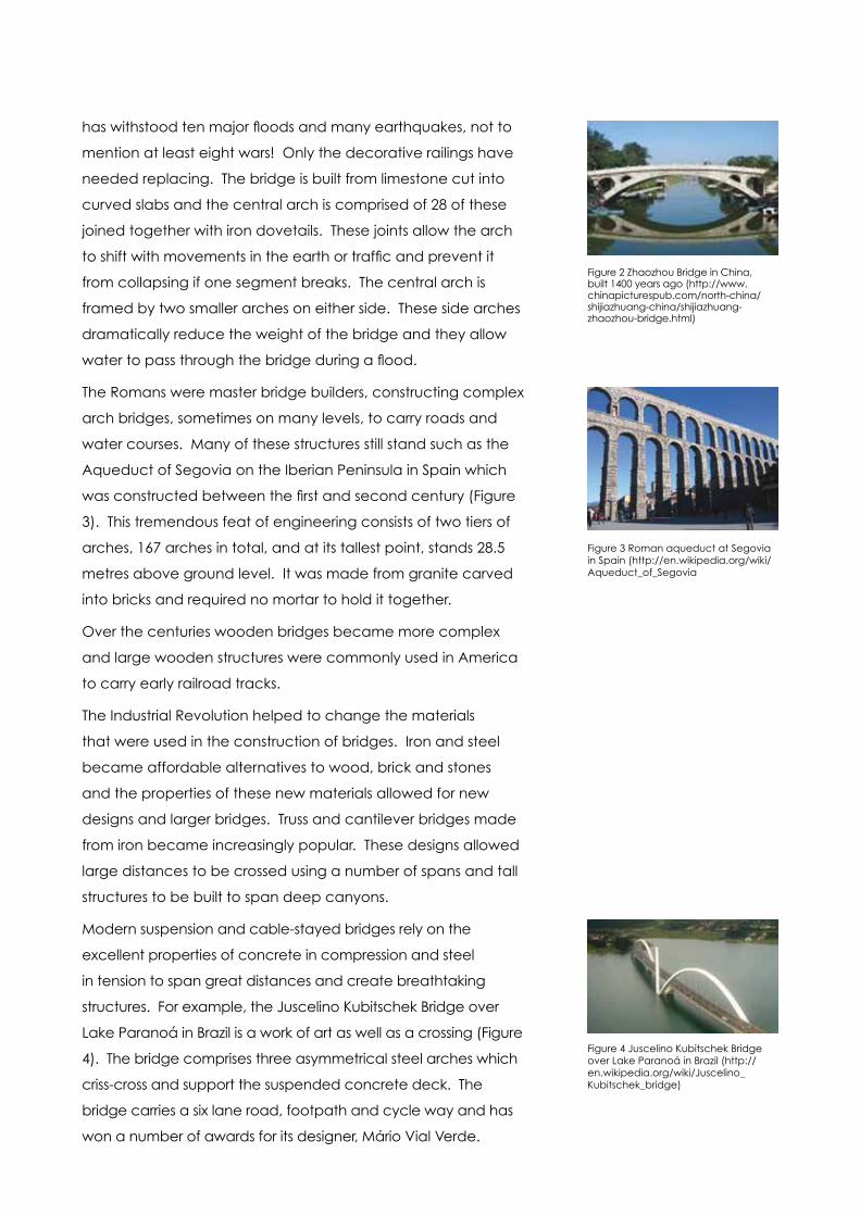
has withstood ten major floods and many earthquakes, not to
mention at least eight wars! Only the decorative railings have
needed replacing. The bridge is built from limestone cut into
curved slabs and the central arch is comprised of 28 of these
joined together with iron dovetails. These joints allow the arch
to shift with movements in the earth or traffic and prevent it
from collapsing if one segment breaks. The central arch is
framed by two smaller arches on either side. These side arches
dramatically reduce the weight of the bridge and they allow
water to pass through the bridge during a flood.
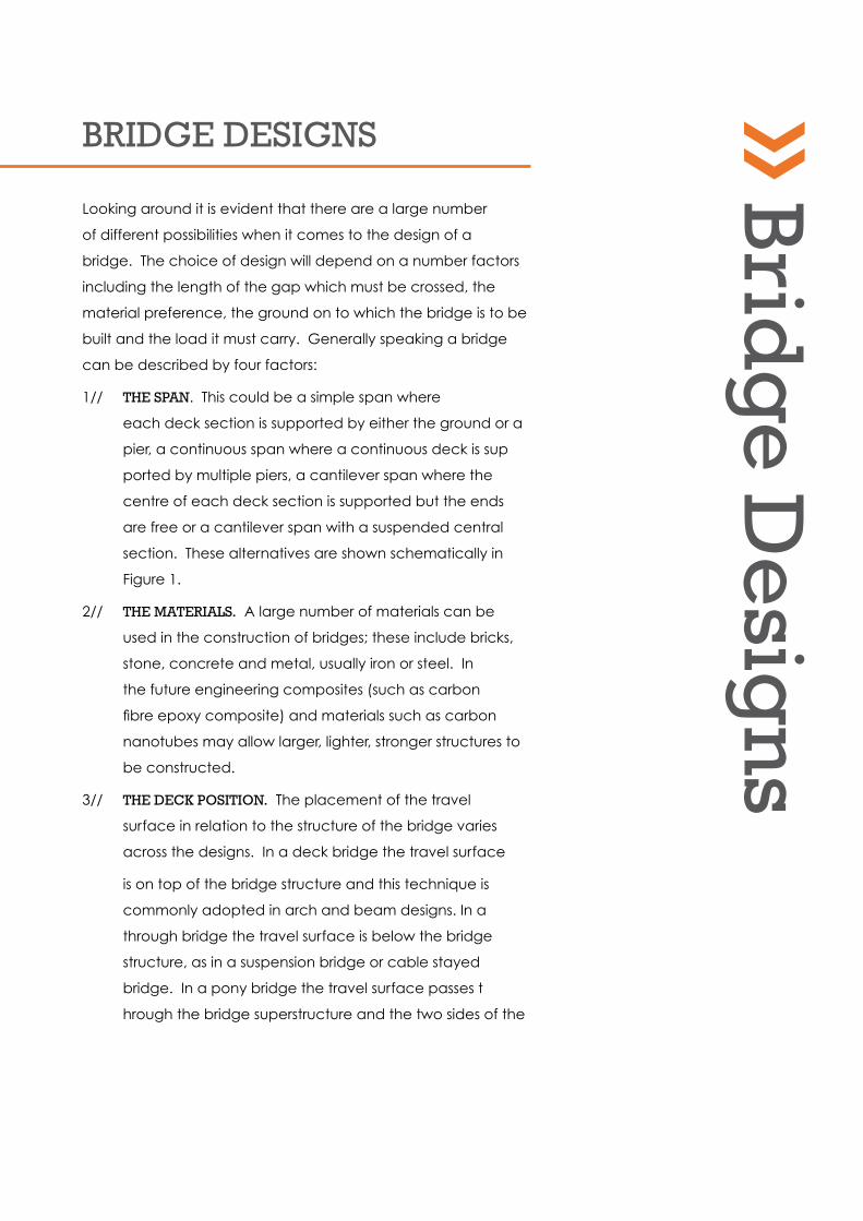
The Romans were master bridge builders, constructing complex
arch bridges, sometimes on many levels, to carry roads and
water courses. Many of these structures still stand such as the
Aqueduct of Segovia on the Iberian Peninsula in Spain which
was constructed between the first and second century (Figure
3). This tremendous feat of engineering consists of two tiers of
arches, 167 arches in total, and at its tallest point, stands 28.5
metres above ground level. It was made from granite carved
into bricks and required no mortar to hold it together.
Over the centuries wooden bridges became more complex
and large wooden structures were commonly used in America
to carry early railroad tracks.
The Industrial Revolution helped to change the materials
that were used in the construction of bridges. Iron and steel
became affordable alternatives to wood, brick and stones
and the properties of these new materials allowed for new
designs and larger bridges. Truss and cantilever bridges made
from iron became increasingly popular. These designs allowed
large distances to be crossed using a number of spans and tall
structures to be built to span deep canyons.
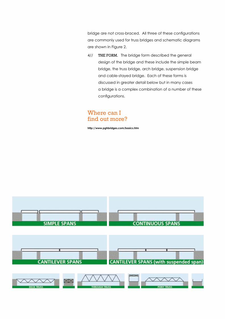
Modern suspension and cable-stayed bridges rely on the
excellent properties of concrete in compression and steel
in tension to span great distances and create breathtaking
structures. For example, the Juscelino Kubitschek Bridge over
Lake Paranoá in Brazil is a work of art as well as a crossing (Figure
4). The bridge comprises three asymmetrical steel arches which
criss-cross and support the suspended concrete deck. The
bridge carries a six lane road, footpath and cycle way and has
won a number of awards for its designer, Mário Vial Verde.
Figure 2 Zhaozhou Bridge in China, built 1400 years ago (http://www.chinapicturespub.com/north-china/shijiazhuang-china/shijiazhuang-zhaozhou-bridge.html)
Figure 3 Roman aqueduct at Segovia in Spain (http://en.wikipedia.org/wiki/Aqueduct_of_Segovia
Figure 4 Juscelino Kubitschek Bridge over Lake Paranoá in Brazil (http://en.wikipedia.org/wiki/Juscelino_Kubitschek_bridge)

In many cases modern bridges use a combination of designs
to successfully span large distances. Suspension and cable-
stayed bridges often have approach sections consisting of
beam, truss or cantilever bridges. These include the second
Severn Crossing (Figure 5), completed in 1996, which consists of
a central cable-stayed section with approach viaducts on both
the English and Welsh sides. The approach viaduct consists of
a total of 49 spans supported on 37 pillars which are just less
than 100 metres apart. Each span is made from 27 segments
which were manufactured off-site from reinforced concrete
and floated into place. The central cable-stayed section has a
span on 456 metres and provides the shipping route along the
deepest channel in the river, the Shoots Channel.
Where can I find out more?http://www.severnbridge.co.uk
http://en.wikipedia.org/wiki/Bridge
http://en.wikipedia.org/wiki/Arkadiko_bridge
Figure 5 The Second Severn Crossing (http://www.flickr.com/photos/beimages/175286033/)
BRIDGE DESIGNS
Looking around it is evident that there are a large number
of different possibilities when it comes to the design of a
bridge. The choice of design will depend on a number factors
including the length of the gap which must be crossed, the
material preference, the ground on to which the bridge is to be
built and the load it must carry. Generally speaking a bridge
can be described by four factors:
1// THE SpaN. This could be a simple span where
each deck section is supported by either the ground or a
pier, a continuous span where a continuous deck is sup
ported by multiple piers, a cantilever span where the
centre of each deck section is supported but the ends
are free or a cantilever span with a suspended central
section. These alternatives are shown schematically in
Figure 1.
2// THE maTERIalS. A large number of materials can be
used in the construction of bridges; these include bricks,
stone, concrete and metal, usually iron or steel. In
the future engineering composites (such as carbon
fibre epoxy composite) and materials such as carbon
nanotubes may allow larger, lighter, stronger structures to
be constructed.
3// THE DEck pOSITION. The placement of the travel
surface in relation to the structure of the bridge varies
across the designs. In a deck bridge the travel surface
is on top of the bridge structure and this technique is
commonly adopted in arch and beam designs. In a
through bridge the travel surface is below the bridge
structure, as in a suspension bridge or cable stayed
bridge. In a pony bridge the travel surface passes t
hrough the bridge superstructure and the two sides of the
Bridg
e Desig
ns
bridge are not cross-braced. All three of these configurations
are commonly used for truss bridges and schematic diagrams
are shown in Figure 2.
4// THE FORm. The bridge form described the general
design of the bridge and these include the simple beam
bridge, the truss bridge, arch bridge, suspension bridge
and cable-stayed bridge. Each of these forms is
discussed in greater detail below but in many cases
a bridge is a complex combination of a number of these
configurations.
Where can I find out more?http://www.pghbridges.com/basics.htm

BEam BRIDGES
Beam bridges are the simplest type of bridge and are the
modern day equivalent of the fallen tree. A beam bridge is
characterised by one or more horizontal beams which span the
gap and rest on supports at either end. The road or walkway
may be the beam itself or it could be attached in sections to
multiple beams to create a simple but effective crossing. The
size of a beam bridge is limited by the length and strength of
the beams as these must carry the weight of the bridge and its
load without sagging. Stiff materials are required to resist bend-
ing as the bridge is effectively put into three-point bend when it
is loaded (i.e. its top surface is put into compression and its low-
er surface tension). This stiffness can be achieved by varying
the geometry of the beams as well as the materials. Therefore
beam bridges are often described by the shape of the beams,
for example, box girder or tubular bridges and girder bridges
which use plates to create an I-beam.
Individual beam bridges do not tend to be longer than about
75 metres so in order to span greater distances a number of
individual beam bridges may be connected together to create
a continuous span. The height of the bridge can be varied by
increasing and decreasing the height of the piers to allow traf-
fic to flow under the bridge. The President Costa e Silva Bridge
(commonly known as the Rio-Niterói Bridge) which connects
Rio de Janeiro and Niterói in Brazil, is a box girder beam bridge
(Figure 2). It utilises piers of increasing height to raise the cen-
tral span 72 metres above the water in order to allow ships to
pass in and out of the bay below. The bridge is 13.29 kilometres
(8.25 miles) long, 72 metres wide and comprises an eight lane
expressway which carries around 140,000 vehicles every day.
The longest bridge in the world was completed in 2000. The
Bang Na Expressway in Bangkok (Figure 3) is an elevated
Beam Brid
ges

Figure 1 Simple beam bridge showing forces during loading (http://science.howstuffworks.com/bridge2.htm)
Figure 3 The Bang Na Bridge in Bang-kok, the longest bridge in the world. (http://4.bp.blogspot.com/_U3GDyUM-C15I/SjGIJXPrHyI/AAAAAAAAAZw/KC3D0TPv6Kg/s1600-h/bang-na-expressway.gif)
Figure 4 Lake Pontchartrain Causeway Bridge in Louisiana, USA (http://www.creativesuite.com/cities-landscapes/5-longest-bridges-in-the-world)
Figure 2 The Rio-Niterói Bridge in Brazil, a box girder beam bridge carrying 140,000 vehicles every day. (http://en.wikipedia.org/wiki/File:Ponte_Rio-Niteroi01_2005-03-15.jpg)
six-lane road which runs for a total of 54 kilometres (just over 33
miles) entirely over land. The viaduct is 27 metres wide and the
distance between supporting pillars is approximately 42 metres.
The deck is made up of concrete box girders and 1.8 million
cubic metres of concrete were used in its construction.
The longest bridge over water is also a continuous span beam
bridge and it is over 38 kilometres (24 miles) long. The Lake
Pontchartrain Causeway Bridge consists of two, two-lane
causeways running parallel to each other (Figure 4). The pre-
stressed concrete deck sections are supported by over 9000
piers creating a southbound carriageway consisting of 2243
spans (opened in 1956) and a northbound carriageway consist-
ing of 1500 spans (opened in 1969). There are seven crossover
sections joining the carriageways, which are 24 metres apart,
which can be used in emergencies. The bridge is not a true
beam bridge though as each causeway has an opening sec-
tion to allow boat traffic to pass.
Where can I find out more?http://en.wikipedia.org/w/index.php?title=beam_bridge
http://www.matsuo-bridge.co.jp/english/bridges/basics/index.shtm
http://www.design-technology.org/beambridges.htm
http://en.wikipedia.org/wiki/Rio-Niter%C3%B3i_bridge
http://www.pbs.org/wgbh/nova/bridge/meetbeam.html
http://www.gnoec.net/causeway_new/default.html
http://www.creativesuite.com/
cities-landscapes/5-longest-bridges-in-the-world
http://science.howstuffworks.com/bridge2.htm
http://en.wikipedia.org/wiki/Bang_Na_Expressway
http://upload.wikimedia.org/wikipedia/commons/0/03/Zhaozhou_Bridge.jpg
arch Brid
ges
aRcH BRIDGES
Arch bridges are amongst some of the oldest surviving exam-
ples of bridges around the world. The central span is supported
by pillars or piers on either side and the curved shape allows
the load to be transferred through to the piers making the struc-
ture very strong. The main disadvantage of the arch bridge is
that complex false work must be built to support the arch dur-
ing construction, limiting the size of the arches that can be built.
The Romans were great arch bridge builders. Their early bridg-
es were made from circular or semicircular arches in which the
arch shape formed a half circle. They constructed their bridges
from stone that was precisely cut to fit to shape without the
need for mortar. They were also the first to construct bridges
from concrete, which they called Opus caementicium. The
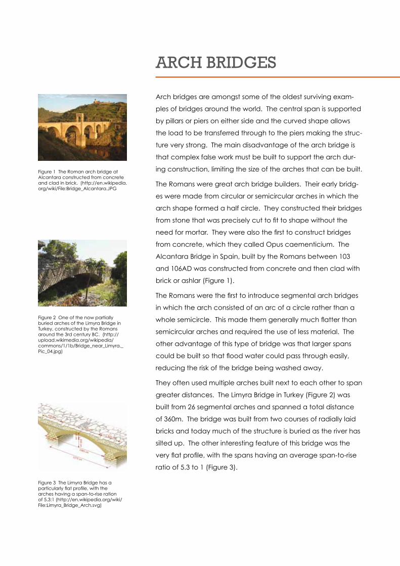
Alcantara Bridge in Spain, built by the Romans between 103
and 106AD was constructed from concrete and then clad with
brick or ashlar (Figure 1).
The Romans were the first to introduce segmental arch bridges
in which the arch consisted of an arc of a circle rather than a
whole semicircle. This made them generally much flatter than
semicircular arches and required the use of less material. The
other advantage of this type of bridge was that larger spans
could be built so that flood water could pass through easily,
reducing the risk of the bridge being washed away.
They often used multiple arches built next to each other to span
greater distances. The Limyra Bridge in Turkey (Figure 2) was
built from 26 segmental arches and spanned a total distance
of 360m. The bridge was built from two courses of radially laid
bricks and today much of the structure is buried as the river has
silted up. The other interesting feature of this bridge was the
very flat profile, with the spans having an average span-to-rise
ratio of 5.3 to 1 (Figure 3).
Figure 1 The Roman arch bridge at Alcantara constructed from concrete and clad in brick. (http://en.wikipedia.org/wiki/File:Bridge_Alcantara.JPG
Figure 2 One of the now partially buried arches of the Limyra Bridge in Turkey, constructed by the Romans around the 3rd century BC. (http://upload.wikimedia.org/wikipedia/commons/1/1b/Bridge_near_Limyra._Pic_04.jpg)
Figure 3 The Limyra Bridge has a particularly flat profile, with the arches having a span-to-rise ration of 5.3:1 (http://en.wikipedia.org/wiki/File:Limyra_Bridge_Arch.svg)
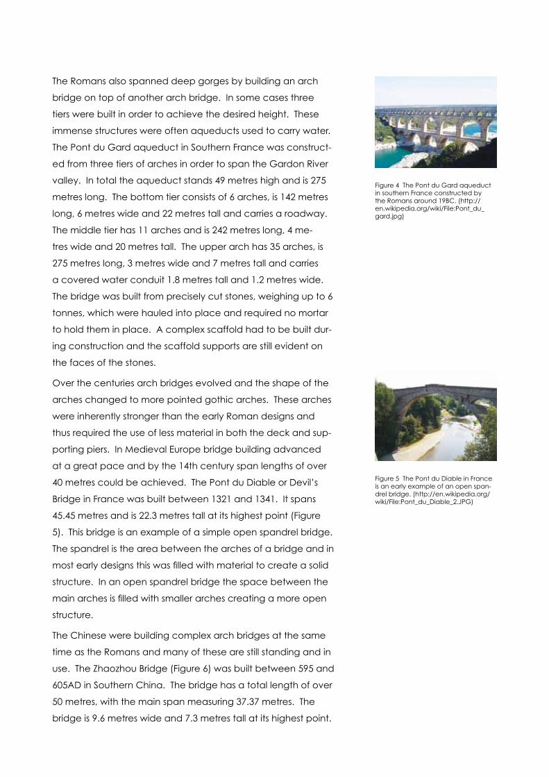
The Romans also spanned deep gorges by building an arch
bridge on top of another arch bridge. In some cases three
tiers were built in order to achieve the desired height. These
immense structures were often aqueducts used to carry water.
The Pont du Gard aqueduct in Southern France was construct-
ed from three tiers of arches in order to span the Gardon River
valley. In total the aqueduct stands 49 metres high and is 275
metres long. The bottom tier consists of 6 arches, is 142 metres
long, 6 metres wide and 22 metres tall and carries a roadway.
The middle tier has 11 arches and is 242 metres long, 4 me-
tres wide and 20 metres tall. The upper arch has 35 arches, is
275 metres long, 3 metres wide and 7 metres tall and carries
a covered water conduit 1.8 metres tall and 1.2 metres wide.
The bridge was built from precisely cut stones, weighing up to 6
tonnes, which were hauled into place and required no mortar
to hold them in place. A complex scaffold had to be built dur-
ing construction and the scaffold supports are still evident on
the faces of the stones.
Over the centuries arch bridges evolved and the shape of the
arches changed to more pointed gothic arches. These arches
were inherently stronger than the early Roman designs and
thus required the use of less material in both the deck and sup-
porting piers. In Medieval Europe bridge building advanced
at a great pace and by the 14th century span lengths of over
40 metres could be achieved. The Pont du Diable or Devil’s
Bridge in France was built between 1321 and 1341. It spans
45.45 metres and is 22.3 metres tall at its highest point (Figure
5). This bridge is an example of a simple open spandrel bridge.
The spandrel is the area between the arches of a bridge and in
most early designs this was filled with material to create a solid
structure. In an open spandrel bridge the space between the
main arches is filled with smaller arches creating a more open
structure.
The Chinese were building complex arch bridges at the same
time as the Romans and many of these are still standing and in
use. The Zhaozhou Bridge (Figure 6) was built between 595 and
605AD in Southern China. The bridge has a total length of over
50 metres, with the main span measuring 37.37 metres. The
bridge is 9.6 metres wide and 7.3 metres tall at its highest point.
Figure 4 The Pont du Gard aqueduct in southern France constructed by the Romans around 19BC. (http://en.wikipedia.org/wiki/File:Pont_du_gard.jpg)
Figure 5 The Pont du Diable in France is an early example of an open span-drel bridge. (http://en.wikipedia.org/wiki/File:Pont_du_Diable_2.JPG)

It is an excellent example of an open spandrel segmental arch
bridge. By using a segmental arch rather than a semicircular
arch master craftsman Li Chun made a weight saving of about
40%. The open spandrels allowed even less material to be
used and the open structure allows flood water to pass through
without risking the bridge being washed away. The bridge
has survived many earthquakes since its construction and part
of the reason for this is the way that the bridge was built. The
main arch consists of 28 thin, curved limestone slabs which are
joined together using iron dovetails. These dovetails allow the
bridge to move and flex and even allow it to stay standing if
one of the stone slabs fails.
All of the arch bridges discussed so far are considered to be
deck arch bridges in which the deck or road way sits entirely
above the arches. In many modern designs the deck is sus-
pended from the main arch by cables or tie bars and the
Sydney Harbour Bridge, completed in 1932, is an example of
this kind of through arch bridge. Modern materials such as steel
and concrete have allowed much larger spans to be built and
an excellent example is the Lupu Bridge in China which has a
central span of 550 metres and an overall length of 3.9 kilome-
tres (Figure 8). This bridge was opened in 2003 but the record
for the longest arch bridge was beaten in 2009 by the steel built
Chaotianmen Bridge, also in China which has a central arch
span on 552 metres.
Figure 6 The Zhaozhou Bridge in China is the oldest surviving example of an open spandrel segmental arch bridge. (http://en.wikipedia.org/wiki/Zhao-zhou_bridge)
Figure 7 Sydney Harbour Bridge is a well known example of a through arch bridge. The main arch is 503 metres wide and 139 metres tall. The deck is 49 metres wide and has a clearance of 49 metres above the water. (http://en.wikipedia.org/wiki/File:Sydney_Har-bour_Bridge_from_Circuilar_Quay.jpg)
Figure 8 The Lupu Bridge in China, built from steel and concrete and opened in 2003 was the longest through arch bridge in the world until 2009. (http://en.wikipedia.org/wiki/File:LupuBridgeandBoats.jpg)
Where can I find out more?http://en.wikipedia.org/wiki/Arch_bridges
http://en.wikipedia.org/wiki/Arch
http://en.wikipedia.org/wiki/Limyra_Bridge
http://en.wikipedia.org/wiki/Pont_du_Gard
http://en.wikipedia.org/wiki/Pont_du_Diable_(C%C3%A9ret)
http://en.wikipedia.org/wiki/Zhaozhou_bridge
http://en.wikipedia.org/wiki/Through_arch_bridge
http://en.wikipedia.org/wiki/Sydney_Harbour_Bridge
http://en.wikipedia.org/wiki/Lupu_Bridge

Truss Bridg
es
http://en.wikipedia.org/wiki/File:General_Hertzog_Bridge_over_Orange_River_at_Aliwal_North.jpg
TRUSS BRIDGES
Truss bridges evolved from simple beam bridges and use a
series of beams and cross-braces to build truss work which
stiffens the structure. As with beam bridges the structure may
comprise just one span or be made up from a number of
shorter spans in order to cross a greater distance. The use a
series of vertical, horizontal and diagonal members which are
in tension or compression allows the construction of a lighter
bridge as not as much material is required compared to a
similar beam bridge design.
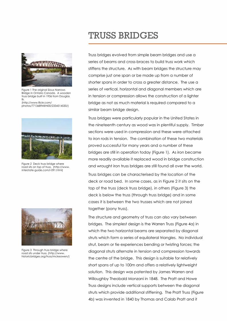
Truss bridges were particularly popular in the United States in
the nineteenth century as wood was in plentiful supply. Timber
sections were used in compression and these were attached
to iron rods in tension. The combination of these two materials
proved successful for many years and a number of these
bridges are still in operation today (Figure 1). As iron became
more readily available it replaced wood in bridge construction
and wrought iron truss bridges are still found all over the world.
Truss bridges can be characterised by the location of the
deck or road bed. In some cases, as in Figure 2 it sits on the
top of the truss (deck truss bridge), in others (Figure 3) the
deck is below the truss (through truss bridge) and in some
cases it is between the two trusses which are not joined
together (pony truss).
The structure and geometry of truss can also vary between
bridges. The simplest design is the Warren Truss (Figure 4a) in
which the two horizontal beams are separated by diagonal
struts which form a series of equilateral triangles. No individual
strut, beam or tie experiences bending or twisting forces; the
diagonal struts alternate in tension and compression towards
the centre of the bridge. This design is suitable for relatively
short spans of up to 100m and offers a relatively lightweight
solution. This design was patented by James Warren and
Willoughby Theobald Monzani in 1848. The Pratt and Howe
Truss designs include vertical supports between the diagonal
struts which provide additional stiffening. The Pratt Truss (Figure
4b) was invented in 1840 by Thomas and Calab Pratt and it
Figure 3 Through truss bridge where road sits under truss. (http://www.historicbridges.org/truss/mckeowen/)
Figure 2 Deck truss bridge where road sits on top of truss. (http://www.interstate-guide.com/i-091.html)
Figure 1 The original Sioux Narrows Bridge in Ontario Canada. A wooden truss bridge built in 1936 from Douglas fir. (http://www.flickr.com/photos/77136894@N00/2334314530/)

was commonly adopted for railway bridges. In this design
all the diagonal struts (with the exception of the two on the
ends) face downwards towards the centre of the bridge, and
these experience tensile forces. The vertical supports are in
compression and help to support the horizontal beams and
prevent them from bending. This type of truss bridge is also
suitable for spans up to about 100m. The Howe Truss (Figure
4c) is the opposite of the Pratt Truss and in this case all of the
diagonal struts face away from the centre of the bridge. The
diagonal struts are in compression and the vertical supports
are in tension. This type of design is relatively rare as it is very
uneconomic for steel bridges. The Howe Truss was named after
its designer, William Howe, and was also patented in 1840.
There are many other variations of truss bridge design, most
named after their inventor and many designed for specific
crossings. Other more common truss designs are shown
schematically in Figure 5.
(a) (b) (c)Figure 4 Three types of truss bridge design: (a) Warren Truss, (b) Pratt Truss and (c) Howe Truss (http://www.matsuo-bridge.co.jp/english/bridges/basics/truss.shtm)
Figure 5 A selection of truss bridge design variations (http://www.pghbridges.com/basics.htm)

The longest truss bridge in the world also holds the record for
the longest cantilever span. The Quebec Bridge crosses the
lower Saint Lawrence River in Canada (Figure 6). The structure
is 987 metres long, 29 metres wide, 104 metres high and the
central span is 549m. The bridge, made from riveted alloy steel,
was opened in 1917 after two disasters during construction in
1907 and 1916 in which many lives were lost. It was originally
designed purely as a railway bridge but today carries a road,
railway and footpath.
Where can I find out more?http://www.saintanthonymain.com/bridges/engineering.php
http://en.wikipedia.org/wiki/Truss_bridge
http://en.wikipedia.org/wiki/Sioux_Narrows_Bridge
http://en.wikipedia.org/wiki/Quebec_Bridge
Figure 6 The Quebec Bridge over the Saint Lawrence River in Canada – the longest truss bridge in the world (http://www.creativesuite.com/cities-landscapes/the-quebec-bridge)
caNTIlEVER BRIDGES
A cantilever bridge is a bridge which utilises a number of
cantilevers to support the deck. A cantilever is a beam which
is supported on one end and free at the other. In the simplest
form of cantilever bridge two cantilever arms project out over
the region to be crossed and are joined in the middle. The
other ends of the arms are supported by pillars at either side
of the obstacle. A further suspended span may be included
in between the two cantilever arms to further increase the
possible span distance (Figure 1). The cantilever arms may
consist of simple beams, however, trusses are commonly
used to improved the stiffness of the deck and allow greater
distances to be spanned.
Construction of a cantilever bridge usually starts with the
construction of the main support pillars. The cantilever arms are
then constructed and extended on site. In order to balance
the structure two cantilever arms are often projected from
either side of the support pillar. Once opposing cantilever
arms meet they are joined together to complete the span.
A suspended span may be raised into position and joined
between two cantilever arms.
The concept of the cantilever was first explored in the mid-
nineteenth century and Heinrich Gerber was the first to obtain
a patent to build a ‘hinged girder’ in 1866. His Hassfurt Bridge in
Germany was completed in 1867 and is recognised as the first
example of a modern cantilever bridge.
One advantage of the cantilever design was that scaffolding
or false work was not needed to support the span during
construction. This allowed deep gorges and other difficult
obstacles to be able to be crossed. The Kentucky River
Bridge spanned a gorge which was 84 metres deep and had
previously been uncrossable.
The Forth Railway Bridge (Figure 2), constructed entirely from
steel girders and opened in 1890 held the record for the
longest cantilever span for 17 years and was considered an
engineering marvel of its time. It is still standing and carries rail
traffic from Edinburgh to the north of Scotland. It still holds the
cantilever Brid
ges

record for the second longest cantilever span in the world with
two spans each 521 metres long).
Although early cantilever bridges were constructed from iron
or steel girders formed into trusses, many modern cantilever
bridges take advantage of the properties of pre-stressed
concrete. Sections of the bridge deck can be cast off-site
and then joined together in-situ to extend the cantilever arms.
The Pierre Pflimlin Bridge shown under construction in Figure
3 crosses the River Rhine between Germany and France. It
was opened in 2002 and was constructed from reinforced
concrete. The sections of the road deck were cast in position
and joined together to form a balanced cantilever. The
central span is 205 metres long and carries two lanes of traffic
along with pedestrian and cycle ways.
Figure 1 Schematic diagram showing parts of a suspended span cantilever bridge with the deck composed of truss sections ( http://en.wikipedia.org/wiki/File:CooperRiverBridge.svg)
Figure 2 Forth Railway Bridge in Scotland constructed entirely from steel and holding the record for the longest cantilever bridge for 17 years. (http://www.edinburghvilla.com/Edin-burghForthRailBridgecrop2.jpg)
Figure 3 Construction of the Pierre Pflimlin Bridge on the border between Germany and France began in the late 1990s and the crossing was opened in 2002.. (http://en.wikipedia.org/wiki/File:Pierre_Pflimlin_Bridge_UC_Adjusted.jpg)
Where can I find out more?http://en.wikipedia.org/wiki/Cantilever_bridges
http://en.wikipedia.org/wiki/Forth_Railway_Bridge
http://en.wikipedia.org/wiki/Pierre_Pflimlin_bridge

Suspension Brid
ges
http://en.wikipedia.org/wiki/File:Great_Belt_Bridge_JvdC.jpg

SUSpENSION BRIDGES
Suspension bridges differ to most other types of bridges in
that a large amount of the structure is under tension rather
than compression. The cables and ties from which the deck
is suspended are placed in tension and the support pillars
experience compressive forces. The load is transferred
vertically down through the pillars and laterally through the
cables. They require little or no false work to support the
structure during construction and as such can be used to span
wide or difficult spaces.
Suspension bridges can be divided into three types. In simple
suspension bridges the deck is placed directly on the main
cables. These cables are only anchored at either end and thus
the bridge takes on a hyperbolic shape. In some cases the
deck is suspended from raised cables which also serve as hand
rails. Since the deck is curved and the load bearing capacity
is limited these bridges are restricted to pedestrian traffic, but
can be built quickly in difficult areas.
The Capilano Suspension Bridge in Canada is 136 metres
long and stands 70 metres above the river. It is a simple
suspension bridge in which the hand rail acts as a support for
the suspended deck. The original bridge was built using hemp
ropes and cedar planks in 1888.
The longest simple suspension bridge in the world is the Arroyo
Cangrejillo Pipeline Bridge in Argentina. The bridge was built
between September 1997 and October 1998 to carry a 1 metre
wide footpath and 0.2 metre diameter copper concentrate
pipeline 337 metres across a 90 metre deep valley on the way
from a nearby copper mine to a railway facility. Construction
of the bridge preserved the natural environment as it meant
that the pipeline did not have to be buried. The open steel
deck is only supported by the main cables and sags by 7.85
metres at its mid-point. The main cables, made from 57 tonnes
of steel, were made by encasing seven galvanised wires in a
wax-filled sheath (for corrosion protection) to create a strand
and then combining thirty seven of these 15 millimetre diameter
strands together in a hexagonal arrangement. In addition to
the main cables, 129 tonnes of structural steel and 250 cubic
metres of reinforced concrete were used in the construction of
the deck and abutments.
Figure 1 Simple suspension bridge in which the deck is supported on the main cables (http://en.wikipedia.org/wiki/File:Bridge-suspension-simple.svg)
Figure 2 The Capilano Bridge in Canada is an example of a simple suspension bridge in which the deck is supported by the hand rail cables. (http://en.wikipedia.org/wiki/File:CapilanoBridge.jpg)
Figure 3 The Arroyo Cangrejillo Bridge in in Argentina is the longest simple suspension bridge in the world with a span of 337 metres. (http://www.ket-chum.org/Cangrejillo/Fig15-700x470.jpg)
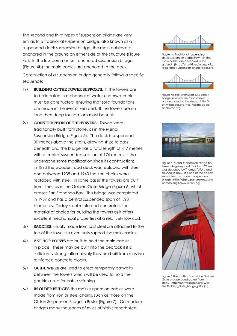
The second and third types of suspension bridge are very
similar. In a traditional suspension bridge, also known as a
suspended-deck suspension bridge, the main cables are
anchored in the ground on either side of the structure (Figure
4a). In the less common self-anchored suspension bridge
(Figure 4b) the main cables are anchored to the deck.
Construction of a suspension bridge generally follows a specific
sequence:
1// BUIlDING OF THE TOWER SUppORTS. If the towers are
to be located in a channel of water underwater piers
must be constructed, ensuring that solid foundations
are made in the river or sea bed. If the towers are on
land then deep foundations must be sunk.
2// cONSTRUcTION OF THE TOWERS. Towers were
traditionally built from stone, as in the Menai
Suspension Bridge (Figure 5). The deck is suspended
30 metres above the straits, allowing ships to pass
beneath and the bridge has a total length of 417 metres
with a central suspended section of 176 metres. It has
undergone some modification since its construction;
in 1893 the wooden road deck was replaced with steel
and between 1938 and 1940 the iron chains were
replaced with steel. In some cases the towers are built
from steel, as in the Golden Gate Bridge (Figure 6) which
crosses San Francisco Bay. This bridge was completed
in 1937 and has a central suspended span of 1.28
kilometres. Today steel reinforced concrete is the
material of choice for building the towers as it offers
excellent mechanical properties at a relatively low cost.
3// SaDDlES, usually made from cast steel are attached to the
top of the towers to eventually support the main cables.
4// aNcHOR pOINTS are built to hold the main cables
in place. These may be built into the bedrock if it is
sufficiently strong; alternatively they are built from massive
reinforced concrete blocks.
5// GUIDE WIRES are used to erect temporary catwalks
between the towers which will be used to hold the
gantries used for cable spinning.
6// IN OlDER BRIDGES the main suspension cables were
made from iron or steel chains, such as those on the
Clifton Suspension Bridge in Bristol (Figure 7). On modern
bridges many thousands of miles of high strength steel
Figure 4a Traditional suspended-deck suspension bridge in whcih the main cables are anchored in the ground. (http://en.wikipedia.org/wiki/File:Bridge-suspension-anchorages.svg)
Figure 5 Menai Suspension Bridge be-tween Anglesey and mainland Wales, was designed by Thomas Telford and finished in 1826. It is one of the earliest examples of a modern suspension bridge. (http://static.panoramio.com/photos/original/5219787.jpg)
Figure 4b Self-anchored suspension bridge in which the main cables are anchored to the deck. (http://en.wikipedia.org/wiki/File:Bridge-self-anchored.svg)
Figure 6 The south tower of the Golden Gate brdoge constructed from steel. (http://en.wikipedia.org/wiki/File:Golden_Gate_bridge_pillar.jpg)
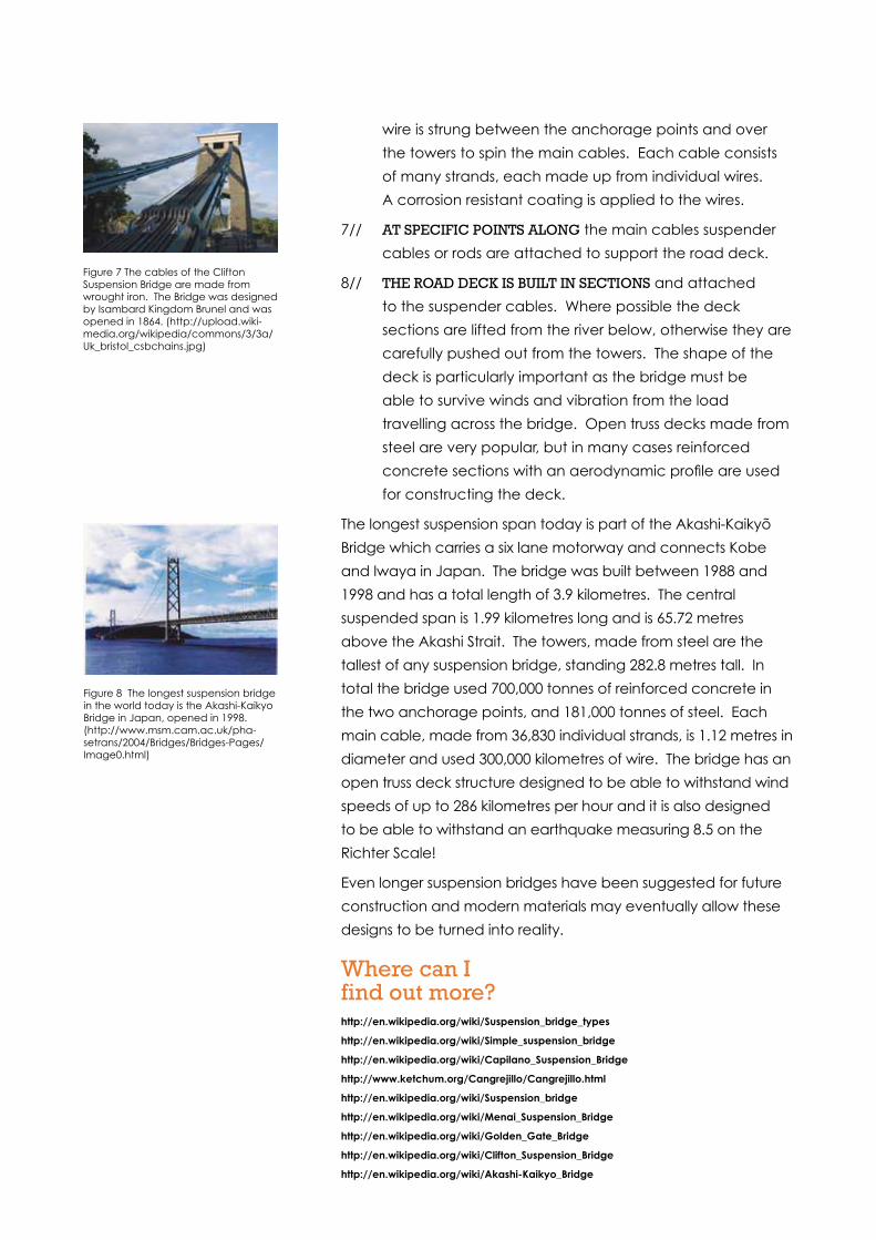
wire is strung between the anchorage points and over
the towers to spin the main cables. Each cable consists
of many strands, each made up from individual wires.
A corrosion resistant coating is applied to the wires.
7// aT SpEcIFIc pOINTS alONG the main cables suspender
cables or rods are attached to support the road deck.
8// THE ROaD DEck IS BUIlT IN SEcTIONS and attached
to the suspender cables. Where possible the deck
sections are lifted from the river below, otherwise they are
carefully pushed out from the towers. The shape of the
deck is particularly important as the bridge must be
able to survive winds and vibration from the load
travelling across the bridge. Open truss decks made from
steel are very popular, but in many cases reinforced
concrete sections with an aerodynamic profile are used
for constructing the deck.
The longest suspension span today is part of the Akashi-Kaikyõ
Bridge which carries a six lane motorway and connects Kobe
and Iwaya in Japan. The bridge was built between 1988 and
1998 and has a total length of 3.9 kilometres. The central
suspended span is 1.99 kilometres long and is 65.72 metres
above the Akashi Strait. The towers, made from steel are the
tallest of any suspension bridge, standing 282.8 metres tall. In
total the bridge used 700,000 tonnes of reinforced concrete in
the two anchorage points, and 181,000 tonnes of steel. Each
main cable, made from 36,830 individual strands, is 1.12 metres in
diameter and used 300,000 kilometres of wire. The bridge has an
open truss deck structure designed to be able to withstand wind
speeds of up to 286 kilometres per hour and it is also designed
to be able to withstand an earthquake measuring 8.5 on the
Richter Scale!
Even longer suspension bridges have been suggested for future
construction and modern materials may eventually allow these
designs to be turned into reality.
Where can I find out more?http://en.wikipedia.org/wiki/Suspension_bridge_types
http://en.wikipedia.org/wiki/Simple_suspension_bridge
http://en.wikipedia.org/wiki/Capilano_Suspension_Bridge
http://www.ketchum.org/Cangrejillo/Cangrejillo.html
http://en.wikipedia.org/wiki/Suspension_bridge
http://en.wikipedia.org/wiki/Menai_Suspension_Bridge
http://en.wikipedia.org/wiki/Golden_Gate_Bridge
http://en.wikipedia.org/wiki/Clifton_Suspension_Bridge
http://en.wikipedia.org/wiki/Akashi-Kaikyo_Bridge
Figure 7 The cables of the Clifton Suspension Bridge are made from wrought iron. The Bridge was designed by Isambard Kingdom Brunel and was opened in 1864. (http://upload.wiki-media.org/wikipedia/commons/3/3a/Uk_bristol_csbchains.jpg)
Figure 8 The longest suspension bridge in the world today is the Akashi-Kaikyo Bridge in Japan, opened in 1998. (http://www.msm.cam.ac.uk/pha-setrans/2004/Bridges/Bridges-Pages/Image0.html)

cab
le-Stayed Brid
ges
http://en.wikipedia.org/wiki/File:Sundialbridge2.jpg
caBlE-STaYED BRIDGES
Cable-stayed bridges are closely related to suspension
bridges in that they are comprised of one or more towers
in compression and a deck suspended from cables which
are in tension. They are not capable of spanning such large
distances as suspension bridges, but can be used for larger
single spans than cantilever or arch bridges.
The most important difference between a cable-stayed
bridge and a suspension bridge is the primary load bearing
component. In a suspension bridge this is the main cables
which are held in tension and transfer the load to the
anchorage points. In a cable-stayed bridge the primary load
bearing structures are the towers to which the supporting
cables are attached. The cables may be attached to the
deck and tower in two different configurations. In a cable-
stayed bridge with a fan or radial design all of the supporting
cables originate from the top of the towers. In a cable-stayed
bridge with a harp or parallel design the supporting cables are
distributed down the length of the tower and run parallel to
each other. The other distinguishing feature of a cable-stayed
bridge is that the deck is also held in compression by the cables
creating a structure which is inherently stiffer than a suspension
bridge. This increased stiffness means that the deck deforms
less under live loading (i.e. when the bridge is in use).
As with suspension bridges, cable-stayed bridges can be
built without the need for false work. Once the towers have
been constructed the deck can be cantilevered out from the
desired height in pieces and the sections held in place by the
supporting cables until they meet. Alternatively the individual
sections may be raised and attached to the cables.
Cable-stayed bridges come in a variety of shapes and sizes,
allowing crossings to be created which are as much a work of
art as a functional structure.
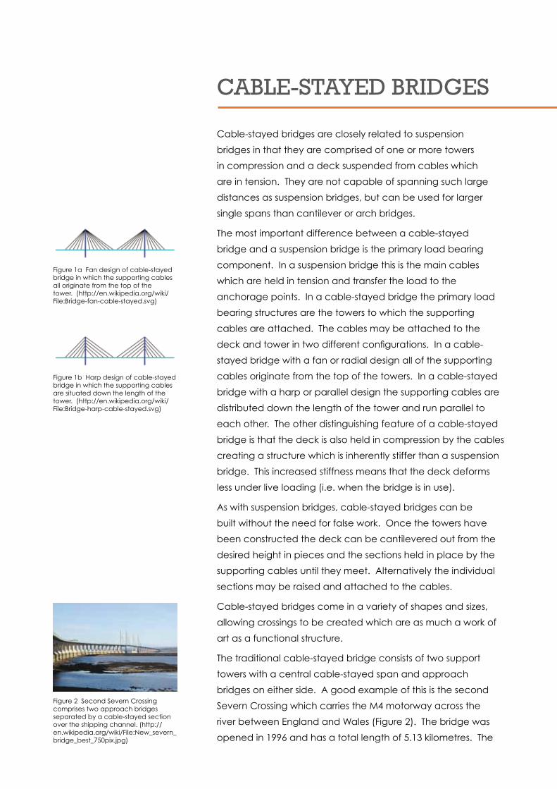
The traditional cable-stayed bridge consists of two support
towers with a central cable-stayed span and approach
bridges on either side. A good example of this is the second
Severn Crossing which carries the M4 motorway across the
river between England and Wales (Figure 2). The bridge was
opened in 1996 and has a total length of 5.13 kilometres. The
Figure 1a Fan design of cable-stayed bridge in which the supporting cables all originate from the top of the tower. (http://en.wikipedia.org/wiki/File:Bridge-fan-cable-stayed.svg)
Figure 1b Harp design of cable-stayed bridge in which the supporting cables are situated down the length of the tower. (http://en.wikipedia.org/wiki/File:Bridge-harp-cable-stayed.svg)
Figure 2 Second Severn Crossing comprises two approach bridges separated by a cable-stayed section over the shipping channel. (http://en.wikipedia.org/wiki/File:New_severn_bridge_best_750pix.jpg)
cable-stayed section is 900 metres long in total with a central
span of 456 metres. The central span rises above the Shoots
Channel – the main shipping lane. The approach viaducts are
slender segmental arch bridges and are supported by 37 piers.
The twin leg towers of the cable-stayed section are 149 metres
tall and made from prestressed concrete. They support the 240
cables which hold the deck in place. The deck is made from
steel plate girders and reinforced concrete and is designed so
that the effect of high winds is minimal.
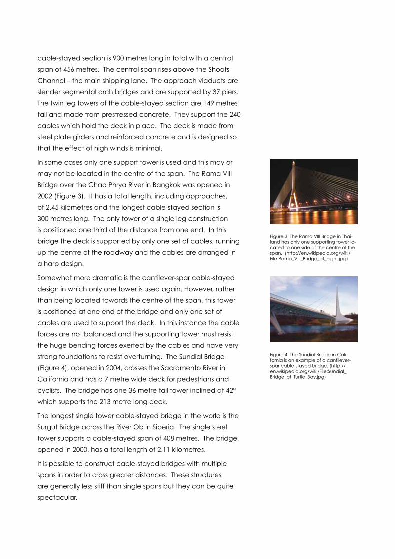
In some cases only one support tower is used and this may or
may not be located in the centre of the span. The Rama VIII
Bridge over the Chao Phrya River in Bangkok was opened in
2002 (Figure 3). It has a total length, including approaches,
of 2.45 kilometres and the longest cable-stayed section is
300 metres long. The only tower of a single leg construction
is positioned one third of the distance from one end. In this
bridge the deck is supported by only one set of cables, running
up the centre of the roadway and the cables are arranged in
a harp design.
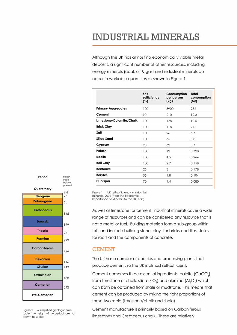
Somewhat more dramatic is the cantilever-spar cable-stayed
design in which only one tower is used again. However, rather
than being located towards the centre of the span, this tower
is positioned at one end of the bridge and only one set of
cables are used to support the deck. In this instance the cable
forces are not balanced and the supporting tower must resist
the huge bending forces exerted by the cables and have very
strong foundations to resist overturning. The Sundial Bridge
(Figure 4), opened in 2004, crosses the Sacramento River in
California and has a 7 metre wide deck for pedestrians and
cyclists. The bridge has one 36 metre tall tower inclined at 42°
which supports the 213 metre long deck.
The longest single tower cable-stayed bridge in the world is the
Surgut Bridge across the River Ob in Siberia. The single steel
tower supports a cable-stayed span of 408 metres. The bridge,
opened in 2000, has a total length of 2.11 kilometres.
It is possible to construct cable-stayed bridges with multiple
spans in order to cross greater distances. These structures
are generally less stiff than single spans but they can be quite
spectacular.
Figure 3 The Rama VIII Bridge in Thai-land has only one supporting tower lo-cated to one side of the centre of the span. (http://en.wikipedia.org/wiki/File:Rama_VIII_Bridge_at_night.jpg)
Figure 4 The Sundial Bridge in Cali-fornia is an example of a cantilever-spar cable-stayed bridge. (http://en.wikipedia.org/wiki/File:Sundial_Bridge_at_Turtle_Bay.jpg)

The Millau Viaduct in France is an excellent example of a
multiple span cable-stayed bridge (Figure 5). It was designed
by architect Norman Foster and structural engineer Michel
Virlogeux and opened to traffic in late 2004. It consists of
seven towers of varying height which support eight spans. The
concrete towers are topped with 87 metre tall masts, each
weighing 700 tonnes, which house eleven cables on each
side that support the deck. The deck has a total length of 2.46
kilometres. It is 32 metres wide, 4.2 metres deep and is made
from 36,000 tonnes of steel. The deck has an inverse aerofoil
cross section in order to resist the high winds which blow down
the valley. The bridge also holds the record for the tallest
supporting towers with the largest standing at 343 metres.
The bridge with the longest cable-stayed span in the world
is the Sutong Bridge in China (Figure 6). The bridge crosses
the Yangzte River and was built between 2003 and 2008. The
bridge has a total length of 8.2 kilometres and consists of a
central cable-stayed span 1.088 kilometres long. On either
side of the central span are a 300 metre long and then two
100 metre long cable-stayed spans and concrete segmental
arch approach viaducts. The support pillars rise to 306 metres
tall and there is a clearance of 62 metres between the deck
and river. The steel deck of the central cable-stayed section
was built off-site in 16 metre long sections, each weighing 450
tonnes. Like the Millau Viaduct the deck has been designed to
resist strong winds.
As with suspension bridges, advances in modern materials will
no doubt lead to the construction of even more impressive
designs.
Where can I find out more?http://en.wikipedia.org/wiki/Cable-stayed_bridge
http://www.pbs.org/wgbh/nova/bridge/meetcable.html
http://www.brantacan.co.uk/cable_stayed.htm
http://en.wikipedia.org/wiki/Second_Severn_Crossing
http://en.wikipedia.org/wiki/Rama_VIII_Bridge
http://en.wikipedia.org/wiki/Sundial_Bridge
http://en.wikipedia.org/wiki/Surgut_Bridge
http://en.wikipedia.org/wiki/Millau_Viaduct
http://en.wikipedia.org/wiki/Sutong_Bridge
Figure 5 The Millau Viaduct across the Tarn Valley in France is a multiple span cable-stayed consisting of eight spans supported by seven towers. (http://dannyogrady.com/images/millau-viaduct-france.jpg)
Figure 6 The Sutong Bridge over the Yangtze Rver in China has the longest cable-stayed span in the world at 1.088 kilometres. (http://www.lqgcs.com/uploads/allimg/200909/1-0Z919141537.jpg)

2 m
aT
ER
IalS

Industrial m
inerals
http://commons.wikimedia.org/wiki/File:Hope_Cement_Works.jpg
INDUSTRIal mINERalS
Although the UK has almost no economically viable metal
deposits, a significant number of other resources, including
energy minerals (coal, oil & gas) and industrial minerals do
occur in workable quantities as shown in Figure 1.
Primary Aggregates
Cement
Limestone/Dolomite/Chalk
Brick Clay
Salt
Silica Sand
Gypsum
Potash
Kaolin
Ball Clay
Bentonite
Barytes
Fluorspar
Self Consumption Totalsufficiency perperson consumption(%) (kg) (Mt)
100 3900 232
90 210 12.3
100 178 10.5
100 118 7.0
100 96 5.7
100 65 3.8
90 62 3.7
100 12 0.728
100 4.5 0.264
100 2.7 0.158
25 3 0.178
55 1.8 0.104
70 1.4 0.080
Figure 1 UK self-sufficiency in industrial minerals, 2002 (from The Economic Importance of Minerals to the UK, BGS)
Figure 2 A simplified geologic time scale (the height of the periods are not drawn to scale)
Quaternary
Period Million years before present
Neogene2.623
65
145
199
251
299
359
416
443
488
542
Palaeogene
Cretaceous
Jurassic
Triassic
Permian
Carboniferous
Devonian
Silurian
Ordovician
Cambrian
Pre-Cambrian
As well as limestone for cement, industrial minerals cover a wide
range of resources and can be considered any resource that is
not a metal or fuel. Building materials form a sub-group within
this, and include building stone, clays for bricks and tiles, slates
for roofs and the components of concrete.
cEmENT
The UK has a number of quarries and processing plants that
produce cement, so the UK is almost self-sufficient.
Cement comprises three essential ingredients: calcite (CaCO3)
from limestone or chalk, silica (SiO2) and alumina (Al2O3) which
can both be obtained from shale or mudstone. This means that
cement can be produced by mixing the right proportions of
these two rocks (limestone/chalk and shale).
Cement manufacture is primarily based on Carboniferous
limestones and Cretaceous chalk. These are relatively

extensive and so are worked in a number of locations across
the UK. Figure 2 shows the relative positions of these periods in
geological time.
A happy coincidence in the manufacture of cement from
limestone is that the limestone and shale required often occur in
the same sequence of sedimentary rocks, so both raw materials
can be extracted from the same (or nearby) quarries.
cement productionThe raw materials are extracted from quarries and crushed in
similar ways to hard rock aggregate quarries. However, in this
case the aim is to get everything down to a very small particle
size, so the material has to be finely ground in a ball mill after
the initial crushing. It is at this point that the limestone or chalk
is carefully mixed with the shale or clay to ensure a completely
homogenous mixture. This grinding and mixing can either take
place dry or wet. Limestone (3% moisture content) is usually
processed dry, whereas chalk (12-16% moisture) is usually
processed wet.
Whether it is wet or dry, the material is then heated (roasted) in a
rotary kiln to a temperature of about 1400°C, where firstly water
and then CO2 are driven off, indicating the decomposition of first
the shale and then the limestone.
Decomposition of the limestone takes the form of:
CaCO3 (s) CaO (s) + CO2 (g)
This process is known as calcination and the products of burning
limestone are quicklime and carbon dioxide. This reaction has
been known for millennia and was one of the first chemical
reactions discovered by humankind. Left to its own devices,
quicklime will reabsorb CO2 from the atmosphere and convert
back to calcium carbonate.
The kiln is tilted so that as the material rotates it passes through
the kiln at a controlled rate. Burning fuel consisting of powdered
coal or natural gas is forced into the lower end of the kiln. The
remaining materials react and fuse to form a cement clinker
which is then cooled.
At this point a further material is added to control the initial rate
of reaction when the cement is mixed with water. Either gypsum
or anhydrite can be used for this purpose, and usually makes up
5% of the final cement. This mixture is then finely ground (to less
than 75 microns in size) to produce what is known as Ordinary
Portland Cement.

cONSTRUcTION aGGREGaTES
The term aggregate is the collective word for sand, gravel and
crushed rock. Aggregates are extracted in very significant
amounts, far in excess of all other industrial minerals combined, and
so they are sometimes considered as a separate group.
Aggregates are normally defined as being hard, granular, materials
which are suitable for use either on their own (compacted to a
firm mass to fill a space) or with the addition of cement, lime or
bituminous binder (for roads) in construction. About 35% of the
aggregates used in the UK each year goes into concrete.
The value of aggregate is relatively low, so a significant
proportion of the total cost is made up of the transport costs. This
is one reason why there are so many quarries scattered around
the UK, as wherever possible, demand will probably be met by
local resources. However, there is a particular problem around
London and the south-east, where demand is extremely high but
the available natural resources are low. Concerns at minimising
environmental impact and at maximising our natural resources,
mean that Primary, Secondary and Recycled Aggregates are
now defined in addition to considering the different sources of
Primary aggregate. Figure 3 gives the amounts of aggregate
produced in each of these groups.
pRImaRY aGGREGaTES
These are produced from naturally occurring mineral deposits,
extracted specifically for use as aggregate and used for the
first time. The source material can be a wide variety of hard
rocks (e.g. limestone, sandstone, basalt, granite) which are then
crushed to the appropriate sizes, or sand and gravel deposits
recovered from a land or marine environment. The UK can be
considered self-sufficient in aggregate as we only import a very
small amount into the south east of England.
The UK has large resources of the different materials suitable for
use as primary aggregates which are distributed quite widely.
They can be divided into crushed rock aggregate and sand &
gravel deposits.
crushed rock aggregateThe suitability of a rock to be crushed as an aggregate depends
on its physical characteristics, such as crushing strength, porosity,
and resistance to impact, abrasion and polishing. Aggregates
range from low to high quality, and concrete requires a
reasonably high quality. This type of material is commonly
derived from hard, dense and cemented sedimentary rock (most
Figure 3 The tonnage of aggregate produced in 2003 from each source (from Construction aggregates, Mineral Planning Factsheet, BGS)
AGGREGATES268Mt
RECyCLED54Mt (20%)
Crushed rock123Mt (60%)
Limestone & dolomite
66.8MtSandstone
11.3MtIgneous 44.8Mt
Land-won 68.1Mt
Marine 12.1Mt
PRIMARy203Mt (76%)
Sand & gravel80.2Mt (40%)
SECONDARy10Mt (4%)

limestones and certain sandstones) and the tougher, crystalline
igneous rocks.
Quarries that excavate hard rock deposits are often large
and deep and require large scale equipment to extract up
to five million tonnes of rock a year (Figures 4 & 5). Sites are
usually active for many years and therefore usually have fixed
processing plant on site (Figure 6).
The method of working is to blast the rock to produce a good
muckpile that can then be loaded into a dump truck by an
excavator or a wheeled vehicle called a front-end loader.
The quarry works down in a series of benches that are usually
between 10 – 15 m high.
The objective of processing of the rock is to gain a range of
different sized fractions which will be used for different purposes.
Typically, a quarry will produce material with a diameter of 40mm,
28mm, 20mm, 14mm, 10mm and 6mm.
lImESTONES Limestones are sedimentary rocks composed
mainly of calcium carbonate (CaCO3). Limestones are common
rock types and are hard and durable and therefore suitable
for aggregate. The main resource and extraction areas are in
the Peak District of Derbyshire, the Mendip Hills, parts of North &
South Wales, parts of the northern Pennines and Lakes District,
and in Northern Ireland.
IGNEOUS aND mETamORpHIc ROck Igneous rocks are
particularly important where other materials are not widespread.
Most igneous rock is used as roadstone or rail ballast, so is not as
relevant to the production of concrete. Resources of igneous
and metamorphic rocks are mainly concentrated in Scotland
and Northern Ireland, mostly in remote upland areas.
However, there are some small outcrops of Cambrian/
Precambrian igneous rock (slightly metamorphosed diorite and
granodiorite intrusions) in Leicestershire. These are a source not
only for the Midlands, but they also serve London and the South
East by good rail links, thus keeping traffic off the roads.
There is one very large granite quarry in Scotland, in the Strontian
Granite on Loch Linne. Glensanda produces about 5 Mt per year,
all of which is transported by ship to London, the south east of
England and north west Europe.
SaNDSTONE The term sandstone covers a wide range of
different rock types, all of which are predominantly comprised of
quartz, but with various amounts of feldspar and rock fragments
in a fine-grained matrix or cement.
The most extensively worked sandstones are those of Upper
Carboniferous age in the Pennines, but they are generally
Figure 4 - Typical hard rock quarry
Figure 5 - Large scale equipment is necessary to extract the rock.
Figure 6 - On-site processing plants are often built alongside quarries.
low quality. Sandstones known as greywackes occur across
Britain and often make very good roadstone because of their
resistance to abrasion and polishing.
SaND aND GRaVEl
These deposits have been formed by the erosion of rocks, mainly
by glacial and river action, which produces fragments that
then accumulate into a sedimentary deposit. Most sand and
gravel is composed of particles that are durable and silica rich
(e.g. quartz and flint), as softer material will degrade rapidly to
produce silt which is of limited use.
laND-WON SaND aND GRaVEl Sand and gravel resources
extracted from land can be conveniently divided into two major
categories. The bedrock (or “solid”) deposits are geologically
older deposits ranging from Permian to Palaoegene in age and
are bedded deposits, often fairly thick, laid down as part of a
sedimentary sequence. The sandy pebble beds that make up
the Triassic Sherwood Sandstone Group (found in the Midlands
and Devon) are conglomerates that are important as coarse
aggregate for concrete. Others are made entirely of sand (e.g.
Permian Yellow Sands of Durham).
The superficial (or “drift”) deposits comprise all sediments laid
down in the last 200 million years as fluvial (river) deposits or
glaciofluvial (glacial meltwater) deposits.
The fluvial deposits commonly occur along the floors and sides of
major river valleys and usually range between 1m and 10m thick.
The Thames, Trent and Severn rivers are all important sources and
the composition of each deposit reflects the upstream geology
(the source of the sand and gravel). For example, the River
Trent deposits contain a high proportion of well sorted quartzite
pebbles from the Triassic Sherwood Sandstone Group.
The glaciofluvial deposits were laid down by the action of glacial
meltwaters. These are often complex in shape and structure and
are not confined to river systems. They can reach over 30m in
thickness, although they may not be very laterally extensive and
may also have a considerable thickness of glacial till (primarily a
clay deposit) lying over them.
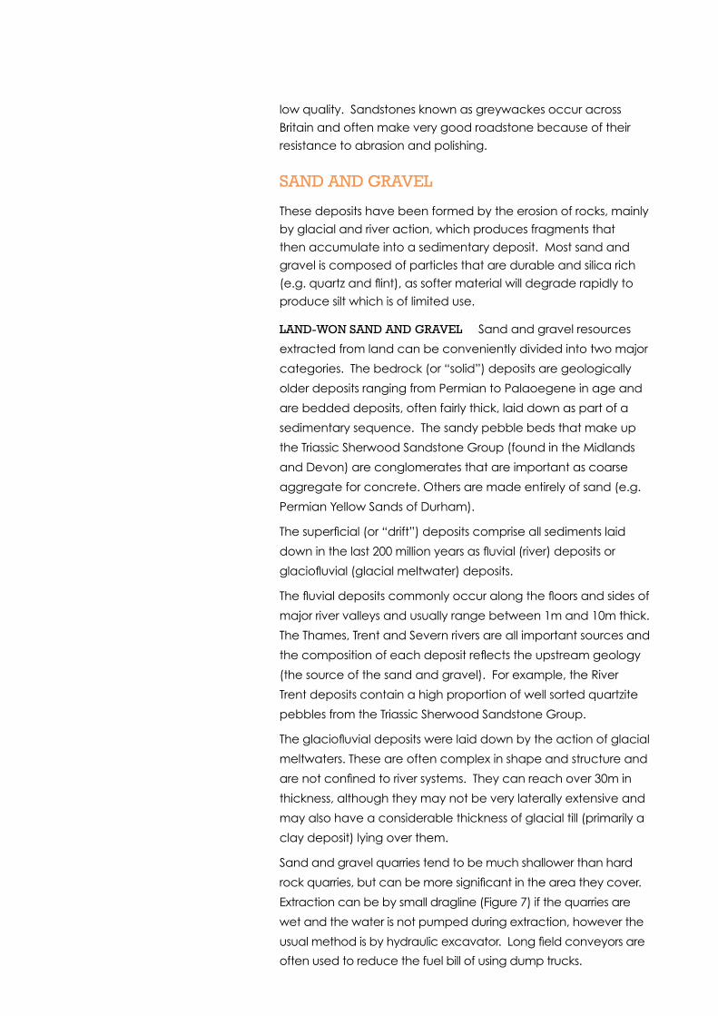
Sand and gravel quarries tend to be much shallower than hard
rock quarries, but can be more significant in the area they cover.
Extraction can be by small dragline (Figure 7) if the quarries are
wet and the water is not pumped during extraction, however the
usual method is by hydraulic excavator. Long field conveyors are
often used to reduce the fuel bill of using dump trucks.
Sand and gravel is normally washed and screened over several
different sizes of aperture, with crushing used to varying degrees
depending on the size of the pebbles and boulders in the
deposit, and on the product required. As the deposit is the result
of rivers and glacial meltwaters, it is possible that it may contain
some organic material (wood or lignite). This usually needs to be
removed before the material is screened into various size ranges
– 20mm, 14mm, 10mm and 6mm.
The sand is classified into coarse and fine sands, but the main
issue here is separating the sand from the very fine silts and clays
which are not required. The method of separation of sand and
silt uses the effect of moving water and the different densities of
the material.
Sand and gravel processing plants tend to use a lot of water,
which quickly becomes contaminated with silt. The water is re-
circulated as much as possible, and the silt rich waters taken to
settling lagoons.
maRINE SaND aND GRaVEl These are very important to the
UK as they are an important source of materials for London and
the South East, where terrestrial sources are limited. While some
of the off-shore deposits are modern marine tidal sand banks,
most of them are directly comparable to the land-won fluvial
and glaciofluvial deposits. These were originally deposited in a
terrestrial environment, but subsequent subsidence and sea-level
rise has resulted in them being located on the sea-floor.
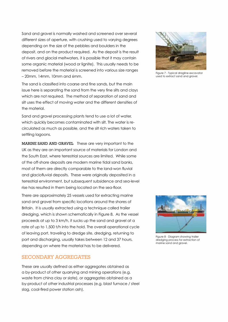
There are approximately 25 vessels used for extracting marine
sand and gravel from specific locations around the shores of
Britain. It is usually extracted using a technique called trailer
dredging, which is shown schematically in Figure 8. As the vessel
proceeds at up to 3 km/h, it sucks up the sand and gravel at a
rate of up to 1,500 t/h into the hold. The overall operational cycle
of leaving port, traveling to dredge site, dredging, returning to
port and discharging, usually takes between 12 and 37 hours,
depending on where the material has to be delivered.
SEcONDaRY aGGREGaTES
These are usually defined as either aggregates obtained as
a by-product of other quarrying and mining operations (e.g.
waste from china clay or slate), or aggregates obtained as a
by-product of other industrial processes (e.g. blast furnace / steel
slag, coal-fired power station ash).
Figure 7 - Typical dragline excavator used to extract sand and gravel.
Figure 8 - Diagram showing trailer dredging process for extraction of marine sand and gravel.
REcYclED aGGREGaTES
These arise from various sources including demolition or
construction of buildings, structures and civil engineering works.
Asphalt planings from resurfaced roads and railway track ballast
can also be used.
aGGREGaTES aND THE ENVIRONmENT
There is no doubt that the extraction of primary aggregate
causes an environmental impact. All quarries are strictly
controlled by local authorities, and have to operate to high
standards and meet a large number of conditions that will
have been attached to the condition to work. The companies
themselves realise they have an obligation to be good
neighbours and to minimise impact, but there will often be
residual noise or dust from a site, or an increase in local traffic.
The problem is exacerbated because many of the resources
form the basis of some of the valued regions of our islands.
Many of the limestones are found in National Parks or Areas
of Outstanding Natural Beauty, and so there can often be a
conflict between the materials required for modern living and
the desire to protect special areas.
However, quarries are often a great opportunity for
environmental and amenity enhancement, particularly in
relation to biodiversity, habitats and nature parks. This applies
to areas owned by the quarry company but not currently being
worked, and to the restoration schemes after the quarry has
finished, which are amongst the best in the world.
While the local effects of the aggregates industry are well
understood and controlled, it is also true that the global effects
(i.e. CO2 emissions) also monitored and reduced at every
opportunity. This is even more important in the cement industry
which uses a significant amount of fuel during processing, and
where CO2 is released in significant quantities as part of the
cement manufacture process.
concrete

cONcRETE
INTRODUcTION
Concrete is a manufactured product and is produced
by combining cement with a mixture of coarse and fine
aggregate and water. Concrete can be placed in-situ or cast
in moulds, where cement and added water undergo a number
of reactions that produce new “minerals” that set hard and
bind the aggregate in place. This produces a highly versatile
building material which is valued for its high compressive
strength, fire resistance, mouldability, impermeability and
durability.
Concrete is the most widely used man-made material around
the world. Enough concrete is made each year for every
individual on the planet to have their own cubic metre – that
amounts to about 7.5 cubic kilometres! Fortunately, the
materials needed to make concrete can all be found in the UK,
which means the extraction and processing takes place here
and we are self-sufficient.
HISTORY OF cONcRETE
Concrete is not the modern material that it might appear to
be. Evidence in Egypt suggests that concrete was used in the
construction of the pyramids and the Romans were pioneers in
concrete construction. Opus caementicium (Roman concrete)
was widely used in the late Roman period for the construction
of buildings, bridges and even underwater structures. Roman
builders often thought the concrete unsightly so many
structures had brick or stone cladding applied to a concrete
core.
Roman concrete was made by mixing quicklime with
pozzolana and aggregate. Pozzolana is a volcanic ash rich
in silica and alumina minerals. These react with the calcium
hydroxide when water is added to create a cementitious
mixture capable of setting under water (Figure 1)
The type of aggregate used depended on the nature of the
construction. In major structural applications such as walls and
foundations heavy stone such as travertine was used giving a
Figure 1 – The Roman baths at Caesarea built from Roman concrete which would set underwater. (http://en.wikipedia.org/wiki/File:Caesarea_Concrete_Bath.jpg)
material with a density of around 2200kgm-3. However, where
weight was an important consideration the aggregate used
was pumice reducing the density of the material to 1350kgm-3.
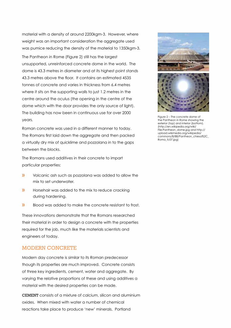
The Pantheon in Rome (Figure 2) still has the largest
unsupported, unreinforced concrete dome in the world. The
dome is 43.3 metres in diameter and at its highest point stands
43.3 metres above the floor. It contains an estimated 4535
tonnes of concrete and varies in thickness from 6.4 metres
where it sits on the supporting walls to just 1.2 metres in the
centre around the oculus (the opening in the centre of the
dome which with the door provides the only source of light).
The building has now been in continuous use for over 2000
years.
Roman concrete was used in a different manner to today.
The Romans first laid down the aggregate and then packed
a virtually dry mix of quicklime and pozzolana in to the gaps
between the blocks.
The Romans used additives in their concrete to impart
particular properties:
Volcanic ash such as pozzolana was added to allow the
mix to set underwater.
Horsehair was added to the mix to reduce cracking
during hardening.
Blood was added to make the concrete resistant to frost.
These innovations demonstrate that the Romans researched
their material in order to design a concrete with the properties
required for the job, much like the materials scientists and
engineers of today.
mODERN cONcRETE
Modern day concrete is similar to its Roman predecessor
though its properties are much improved. Concrete consists
of three key ingredients, cement, water and aggregate. By
varying the relative proportions of these and using additives a
material with the desired properties can be made.
cEmENT consists of a mixture of calcium, silicon and aluminium
oxides. When mixed with water a number of chemical
reactions take place to produce ‘new’ minerals. Portland
Figure 2 – The concrete dome of the Pantheon in Rome showing the exterior (top) and interior (bottom). (http://en.wikipedia.org/wiki/File:Pantheon_dome.jpg and http://upload.wikimedia.org/wikipedia/commons/8/88/Pantheon_chiesa%2C_Roma_fc07.jpg)
cement (OPC) is the most commonly used type of cement.
The main source of the calcium compounds in Portland
cement is limestone and obtaining this material can lead to
controversy as it is quarried from areas of natural beauty. It
is possible to replace some of the OPC with cementitious
materials from other sources. Fly ash, a by-product of coal fired
power stations and ground granulated blast furnace slag, a by-
product from steel production, can be used replace up to 60%
and 80% of the OPC in concrete respectively.
WaTER reacts with the cement to produce glue which binds
the aggregate particles together. The amount of water used
depends on the flow properties required. Adding more water
allows the cement mixture to flow freely and fill voids between
aggregate particles. Using less water produces a stiffer mix
which gives a stronger more durable concrete, but it does not
flow so easily.
aGGREGaTE usually takes two forms: fine and coarse. The
main fine aggregate used is sand and coarse aggregates
include natural gravel and crushed rock. Recycled materials
are increasingly being used in concrete and such materials
include demolition rubble and blast furnace slag.
aDDITIVES are used to change the properties of the concrete
and make it more suitable for the particular application.
Accelerators and retarders are used to either speed up or
slow down the hardening process. Plasticisers increase the
workability of the concrete allowing less water to be used.
Additives which entrap tiny air bubbles in the concrete help to
increase durability by reducing frost damage but they have a
detrimental effect on the compressive strength of the material.
Pigments may be added to change the colour of the concrete
to improve its appearance.
properties of concreteConcrete is a material that is good in compression but its
tensile properties are significantly poorer; the tensile strength
of concrete may be 10% to 15% lower than its compressive
strength. The aggregate carries the compressive load very
efficiently, however, the cement matrix holding the aggregate
particle together is weak in tension and can crack leading to
failure. It is possible to overcome this problem by reinforcing
the concrete with a material that is good in tension. The
ultimate tensile strength is influenced by the ratio of water and
cement (or other cementitious materials). In general the lower
the water content the stronger the material.
Shrinkage and cracking can lead to problems in concrete
structures. As the chemical reaction in the material proceeds
the material shrinks and this process can continue for days,
weeks or even many years. This shrinkage can lead to internal
stresses in the material and surface cracking.
cONcRETE pROcESSING
The way in which concrete is produced and processed varies
depending on how it is to be poured and formed to shape.
The chemical reaction between the cement and water starts
as soon as they are mixed so time is of the utmost importance
as there is a limited window for pouring the concrete into
position.
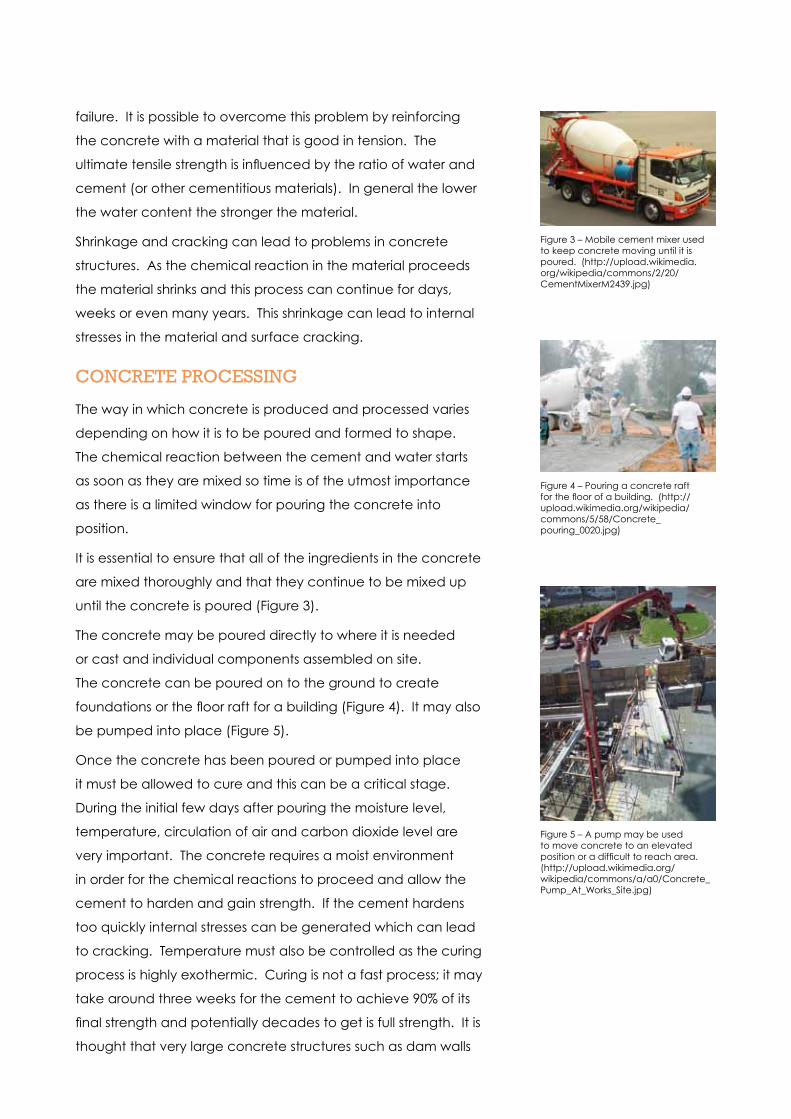
It is essential to ensure that all of the ingredients in the concrete
are mixed thoroughly and that they continue to be mixed up
until the concrete is poured (Figure 3).
The concrete may be poured directly to where it is needed
or cast and individual components assembled on site.
The concrete can be poured on to the ground to create
foundations or the floor raft for a building (Figure 4). It may also
be pumped into place (Figure 5).
Once the concrete has been poured or pumped into place
it must be allowed to cure and this can be a critical stage.
During the initial few days after pouring the moisture level,
temperature, circulation of air and carbon dioxide level are
very important. The concrete requires a moist environment
in order for the chemical reactions to proceed and allow the
cement to harden and gain strength. If the cement hardens
too quickly internal stresses can be generated which can lead
to cracking. Temperature must also be controlled as the curing
process is highly exothermic. Curing is not a fast process; it may
take around three weeks for the cement to achieve 90% of its
final strength and potentially decades to get is full strength. It is
thought that very large concrete structures such as dam walls
Figure 3 – Mobile cement mixer used to keep concrete moving until it is poured. (http://upload.wikimedia.org/wikipedia/commons/2/20/CementMixerM2439.jpg)
Figure 4 – Pouring a concrete raft for the floor of a building. (http://upload.wikimedia.org/wikipedia/commons/5/58/Concrete_pouring_0020.jpg)
Figure 5 – A pump may be used to move concrete to an elevated position or a difficult to reach area. (http://upload.wikimedia.org/wikipedia/commons/a/a0/Concrete_Pump_At_Works_Site.jpg)

could take hundreds of years to cure fully.
The largest continuously poured concrete raft was built in
2007 in Abu Dhabi and formed part of the foundations for
the Landmark Tower. It comprised 16,000 cubic metres of
concrete poured in two days. In 2009 concrete was pumped
to a height of 715 metres during the construction of the Parbati
hydro-electric power project in India, this still holds the world
record for the highest vertical concrete pump. These records
pale into insignificance when the largest concrete pour in a
single project is considered. The Three Gorges Dam in China is
comprised of 16 million cubic metres of concrete poured over
a period of 17 years (Figure 6).
STEEl REINFORcED cONcRETE
Reinforcing concrete with materials such as steel produces
a composite material with the best properties of both
constituents: concrete offers excellent properties in
compression and steel offers excellent properties in tension.
Steel is a suitable reinforcing material as it has a similar
coefficient of thermal expansion to concrete. This means
that internal stresses resulting from temperature changes are
eliminated reducing the risk of cracking. In addition concrete
forms an excellent bond with steel allowing stresses to be
transmitted between the two materials efficiently and the
alkaline nature of the concrete causes a passivating film to
develop on the surface of the steel thus improving its corrosion
resistance. However, it is still vital to ensure that water cannot
penetrate the concrete and reach the steel rebar. One of the
main causes of failure in reinforced concrete is failure of the
steel rebar through corrosion.
The steel reinforcement may take various forms such as bars
(rebar), grids, fibres or plates and reinforced concrete can be
classified as either precast or cast in-situ.
pREcaST REINFORcED cONcRETE is made by making a
mould in the shape of the desired component and then
placing the desired reinforcement in place before casting the
concrete. The reinforcing bars may be placed under tension
prior to casting and the load removed once the concrete
has solidified. This produces concrete which is pre-stressed in
Figure 6 – The Three Gorges Dam in China holds the world record for the largest concrete pour in a single project. (http://upload.wikimedia.org/wikipedia/commons/7/7c/Dreischluchtendamm_hauptwall_2006.jpg)
Figure 7 – Diagram showing the effect of pre-stressed steel reinforcement on the behaviour of a concrete bar.1 & 2 shows how the concrete bar deflects (pink) when a load is applied to its top surface.3 & 4 show how the concrete can be placed in compression by incorporating a steel bar in tension into the casting.5 & 6 show how the pre-stressed concrete bar deflects when a load is applied to its top surface. The load must first overcome the internal compressive stress before causing further deflection.(http://en.wikipedia.org/wiki/Prestressed_concrete)

compression to limit the effect of tensile loads applied during
use. Figure 7 shows how pre-stressing concrete affects the
material during loading. Pre-stressing is used in the manufacture
of beams, lintels and posts which are used for building high-rise
buildings and bridges amongst other things. The main drawback
with making precast sections is size; the components must be
able to be transported to site for assembly.
When caSTING cONcRETE IN-SITU the reinforcement can
be added in two ways. The first option is by far the simplest
and can be used when making floor rafts. Once the concrete
is poured rebar frames are placed and a further layer of
concrete added (Figure 8). When more complex shapes are
required a cage of rebar is constructed and then wooden
shuttering is assembled around this to form a temporary mould
into concrete is poured (Figure 9). Large structures can be
built using this method as the wooden shuttering can be slowly
moved and additional rebar frame constructed. Tall buildings
and bridge pylons are built using this technique.
OTHER REINFORcING maTERIalS
In some applications it is not possible to use steel as the
reinforcing material. For example, MRI scanners are built from
concrete but steel cannot be used for the reinforcement as it
would interact with the large magnets.
It is possible to add glass or plastic fibres or rebar made from
fibre reinforced plastic (FRP) to concrete to offer reinforcement.
These materials are all less dense than steel and so will not
produce such a heavy material. This is of particular importance
when trying to minimise weight. The advantage of using fibre
reinforcement is that it stabilises the concrete during the initial
stages of the curing process thus helping to prevent cracking.
It does not add strength to the concrete in the same way as
steel rebar. Steel and polymer or glass fibres may be used
together to give the best overall properties.
Figure 8 – Installing a steel mesh in to a wet concrete floor raft to provide reinforcement. (http://upload.wikimedia.org/wikipedia/commons/0/04/Concrete_rebar_0030.jpg)
Figure 9 – Complex network of rebar in the roof of the Sagrada Familia in Barcelona prior to concrete pouring. (http://en.wikipedia.org/wiki/File:SagradaFamiliaRoof2.jpg

SUmmaRY
We have been using concrete for over 2000 years to build
sustainable and enduring structures. It is an ideal choice in the
construction of bridges and buildings, particularly when steel
reinforcement is added and it is little wonder that it is the most
commonly used man-made structural material
Where can I find out more?http://en.wikipedia.org/wiki/Concrete
http://en.wikipedia.org/wiki/Roman_concrete
http://en.wikipedia.org/wiki/Pozzolana
http://en.wikipedia.org/wiki/Pantheon,_Rome
http://www.romanconcrete.com
http://en.wikipedia.org/wiki/Properties_of_concrete
http://en.wikipedia.org/wiki/Portland_cement
http://en.wikipedia.org/wiki/reinforced_concrete
http://en.wikipedia.org/wiki/Prestressed_concrete
http://en.wikipedia.org/wiki/Fibre_reinforced_concrete
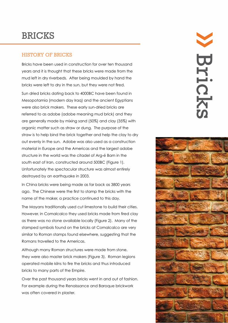
BRIckS
HISTORY OF BRIckS
Bricks have been used in construction for over ten thousand
years and it is thought that these bricks were made from the
mud left in dry riverbeds. After being moulded by hand the
bricks were left to dry in the sun, but they were not fired.
Sun dried bricks dating back to 4000BC have been found in
Mesopotamia (modern day Iraq) and the ancient Egyptians
were also brick makers. These early sun-dried bricks are
referred to as adobe (adobe meaning mud brick) and they
are generally made by mixing sand (50%) and clay (35%) with
organic matter such as straw or dung. The purpose of the
straw is to help bind the brick together and help the clay to dry
out evenly in the sun. Adobe was also used as a construction
material in Europe and the Americas and the largest adobe
structure in the world was the citadel of Arg-é Bam in the
south east of Iran, constructed around 500BC (Figure 1).
Unfortunately the spectacular structure was almost entirely
destroyed by an earthquake in 2003.
In China bricks were being made as far back as 3800 years
ago. The Chinese were the first to stamp the bricks with the
name of the maker, a practice continued to this day.
The Mayans traditionally used cut limestone to build their cities.
However, in Comalcalco they used bricks made from fired clay
as there was no stone available locally (Figure 2). Many of the
stamped symbols found on the bricks at Comalcalco are very
similar to Roman stamps found elsewhere, suggesting that the
Romans travelled to the Americas.
Although many Roman structures were made from stone,
they were also master brick makers (Figure 3). Roman legions
operated mobile kilns to fire the bricks and thus introduced
bricks to many parts of the Empire.
Over the past thousand years bricks went in and out of fashion.
For example during the Renaissance and Baroque brickwork
was often covered in plaster.
Bricks

The speed of construction in brick meant that it was the
preferred building material for factories built during the
Industrial Revolution, even though stone was easily available.
Many cotton mills in the North West were built from bricks and
brick bridges helped the extensive rail network to develop
during this time of rapid industrial expansion. The 27-arch
Stockport Viaduct over the River Mersey was completed in
1840 and was the largest viaduct in the world when it was
built (Figure 4). The structure took just 21 months to erect and
contains over 11 million common bricks!
Although bricks are still used extensively for domestic dwellings,
their use for commercial buildings has deceased over the past
200 years. Materials such as concrete and steel are more
suited to high rise structures as they are stronger and allow
more open designs to be built.
BRIck makING
A variety of techniques and materials are used in the
manufacture of bricks, but in each case roughly the same
procedure is followed.
Obtaining and preparing the raw materials
Bricks can be made from a wide range of materials but clay
is by far the most common. Clay is a mixture of fine-grained
(particles less than 2µm) minerals generated by the long-term
chemical erosion of silicate-bearing rocks. These minerals may
be deposited at their erosion site but are often transported
from their site of origin and laid down elsewhere. Clays
deposits found at the formation site are known as primary clays
or kaolins. Secondary clays are those which are located away
from the site of formation. Many types of pure clay exist, with
subtle differences in mineral content, but most clay deposits
contain a mixture of different types producing a range of
colours ranging from a deep red to dull grey.
The clay is dug out of the ground, either by hand or with
machinery, depending on the size of the operation, and
prepared prior to moulding into bricks. Preparation involves
allowing the clay to dry out slightly and then grinding the
material to achieve the desired grain size. The water content
of the clay is carefully controlled to ensure that the material is
Figure 1 - The Arg-é Bam citadel in Iran was the largest adobe structure in the world until it was destroyed by an earthquake in 2003. This is just one small part of the huge, sprawling complex that was built 2500 years ago. (http://en.wikipedia.org/wiki/File:Arge_Bam_Arad_edit.jpg)
Figure 2 The Mayans used fired bricks made from clay to build the city of Comalcalco as no stone was available locally. (http://www.mexconnect.com/articles/1241-did-you-know-mayan-pyramid-in-tabasco-mexico-has-possi-ble-roman-links)
Figure 3 - The Romans used mobile kilns to make bricks where ever they went. This is a fine example of a Roman brick wall with embedded arches. (http://www.architectureweek.com/2005/0803/images/surfaces_B129.
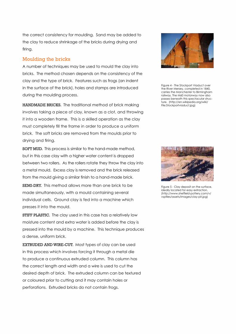
the correct consistency for moulding. Sand may be added to
the clay to reduce shrinkage of the bricks during drying and
firing.
moulding the bricksA number of techniques may be used to mould the clay into
bricks. The method chosen depends on the consistency of the
clay and the type of brick. Features such as frogs (an indent
in the surface of the brick), holes and stamps are introduced
during the moulding process.
HaNDmaDE BRIckS. The traditional method of brick making
involves taking a piece of clay, known as a clot, and throwing
it into a wooden frame. This is a skilled operation as the clay
must completely fill the frame in order to produce a uniform
brick. The soft bricks are removed from the moulds prior to
drying and firing.
SOFT mUD. This process is similar to the hand-made method,
but in this case clay with a higher water content is dropped
between two rollers. As the rollers rotate they throw the clay into
a metal mould. Excess clay is removed and the brick released
from the mould giving a similar finish to a hand-made brick.
SEmI-DRY. This method allows more than one brick to be
made simultaneously, with a mould containing several
individual cells. Ground clay is fed into a machine which
presses it into the mould.
STIFF plaSTIc. The clay used in this case has a relatively low
moisture content and extra water is added before the clay is
pressed into the mould by a machine. This technique produces
a dense, uniform brick.
ExTRUDED aND WIRE-cUT. Most types of clay can be used
in this process which involves forcing it through a metal die
to produce a continuous extruded column. This column has
the correct length and width and a wire is used to cut the
desired depth of brick. The extruded column can be textured
or coloured prior to cutting and it may contain holes or
perforations. Extruded bricks do not contain frogs.
Figure 4 - The Stockport Viaduct over the River Mersey, completed in 1840, carries the Manchester to Birmingham railway. The M60 motorway now also passes beneath this spectacular struc-ture. (http://en.wikipedia.org/wiki/File:Stockportviaduct.jpg)
Figure 5 - Clay deposit on the surface, ideally located for easy extraction. (http://www.sheffield-pottery.com/v/vspfiles/assets/images/clay-pit.jpg)
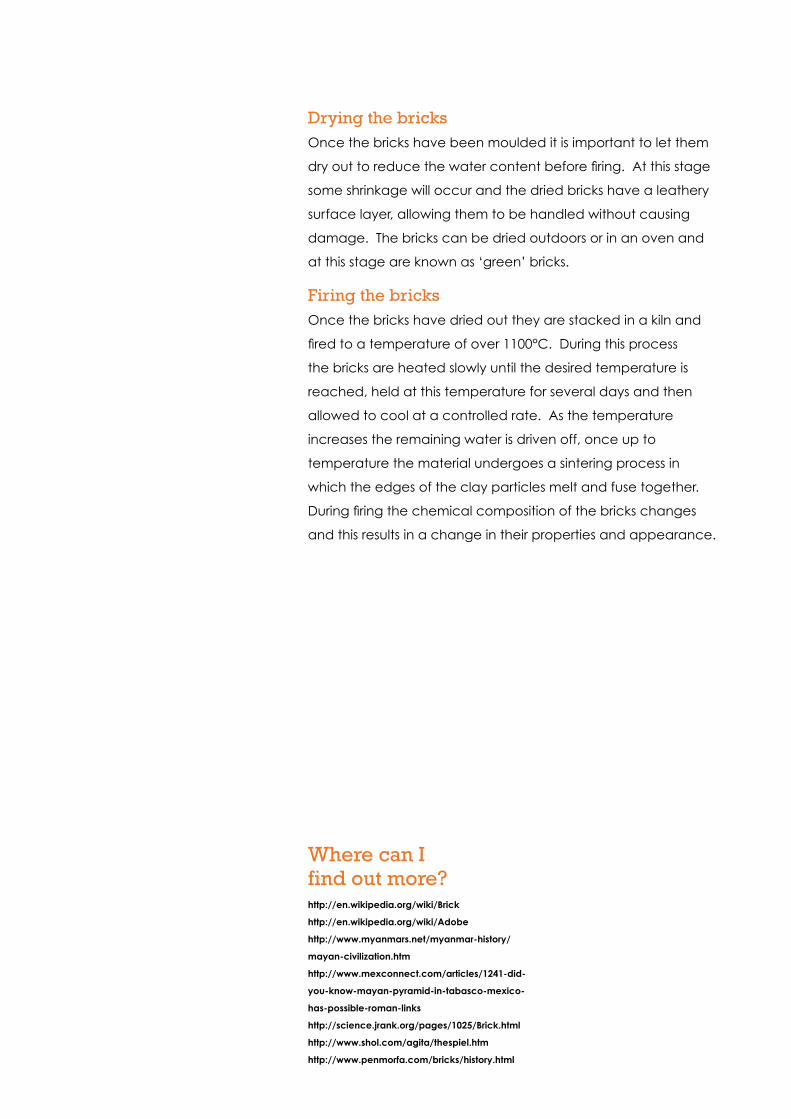
Drying the bricksOnce the bricks have been moulded it is important to let them
dry out to reduce the water content before firing. At this stage
some shrinkage will occur and the dried bricks have a leathery
surface layer, allowing them to be handled without causing
damage. The bricks can be dried outdoors or in an oven and
at this stage are known as ‘green’ bricks.
Firing the bricksOnce the bricks have dried out they are stacked in a kiln and
fired to a temperature of over 1100°C. During this process
the bricks are heated slowly until the desired temperature is
reached, held at this temperature for several days and then
allowed to cool at a controlled rate. As the temperature
increases the remaining water is driven off, once up to
temperature the material undergoes a sintering process in
which the edges of the clay particles melt and fuse together.
During firing the chemical composition of the bricks changes
and this results in a change in their properties and appearance.
Where can I find out more?http://en.wikipedia.org/wiki/Brick
http://en.wikipedia.org/wiki/Adobe
http://www.myanmars.net/myanmar-history/
mayan-civilization.htm
http://www.mexconnect.com/articles/1241-did-
you-know-mayan-pyramid-in-tabasco-mexico-
has-possible-roman-links
http://science.jrank.org/pages/1025/Brick.html
http://www.shol.com/agita/thespiel.htm
http://www.penmorfa.com/bricks/history.html
Iron

IRON
INTRODUcTION
Iron is the sixth most abundant element in the Universe and the
most common element in the Earth as a whole, as the core of
the planet is thought to be comprised mainly of an iron and
nickel alloy. Iron is only the fourth most abundant element in the
crust and it rarely occurs in its native form as it oxidises readily to
form minerals such as haematite and magnetite.
Man has been using iron for many thousands of years and the
first iron artefacts were probably made from iron occurring in
metallic meteorites. Spear tips, daggers and ornaments made
from iron have been found dating back to 4000BC and it is
mentioned in both the Bible and Qur’an. Smelted iron objects
appeared in Mesopotamia as far back as 3500BC. These
can be distinguished from meteoric iron by the lack of nickel
(metallic meteorites are generally composed of an iron-nickel
alloy). It is thought that early iron production occurred as a
by-product of copper refining which was being carried out for
bronze production and deliberate smelting of iron started in
the Middle Bronze Age. The iron produced was very impure,
containing a large amount of carbon. The Chinese developed
early blast furnace technology towards the end of the Zhou
Dynasty in around 550BC. They produced furnaces which would
reach temperatures of over 1000°C and produced carbon-rich
pig iron.
Today iron is the most commonly used metal, but it is not often
used in its elemental form. Iron alloys, chiefly steel, have helped
to shape the modern world and their wide range of properties
has led to their use in vast number of applications.
Structure and properties of ironIron is a grey lustrous metal with atomic number 26 and relative
atomic mass 55.8 and it sits in the first transition series in the
Periodic Table between manganese and cobalt. Some of the
key properties of iron are presented in Figure 2.
Iron can exist in a number of allotropic forms(Figure 3) and
indeed on solidification undergoes phase transformations
through these various structures before settling on a body-
centred cubic (bcc) structure at room temperature. On
solidification from the melt iron adopts a bcc structure and
this form is known as δ-iron. At 1394°C iron undergoes a solid
Figure 1 – Metallic meteorite comprising an iron-nickel alloy. (http://www.meteorites.wustl.edu/id/gibeon_slice_rlk_1285l.jpg)
Figure 2 – Some key properties of iron
Physical properties
Density 7874kgm3
Melting point 1536°C
Boiling point 2861°C
Atomic properties
Crystal structure at RT Body centred
cubic
Electronegativity (Pauling Scale) 1.83
Atomic radius 126pm
Mechanical properties
Ultimate l 10MPa
tensile Cold worked Fe 11000MPa
Young's modulus 211GPa
Mohs hardness 4.0
Ultimatetensilestrength
Pure Fe single crystal
Cold workedFe 690MPa
Fe whisker 11000MPa
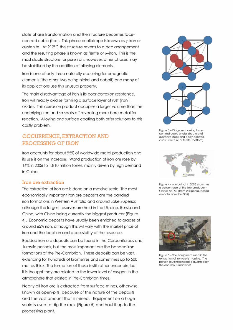
state phase transformation and the structure becomes face-
centred cubic (fcc). This phase or allotrope is known as γ–iron or
austenite. At 912°C the structure reverts to a bcc arrangement
and the resulting phase is known as ferrite or α–iron. This is the
most stable structure for pure iron, however, other phases may
be stabilised by the addition of alloying elements.
Iron is one of only three naturally occurring ferromagnetic
elements (the other two being nickel and cobalt) and many of
its applications use this unusual property.
The main disadvantage of iron is its poor corrosion resistance.
Iron will readily oxidise forming a surface layer of rust (iron II
oxide). This corrosion product occupies a larger volume than the
underlying iron and so spalls off revealing more bare metal for
reaction. Alloying and surface coating both offer solutions to this
costly problem.
OccURRENcE, ExTRacTION aND pROcESSING OF IRON
Iron accounts for about 95% of worldwide metal production and
its use is on the increase. World production of iron ore rose by
16% in 2006 to 1,810 million tones, mainly driven by high demand
in China.
Iron ore extractionThe extraction of iron ore is done on a massive scale. The most
economically important iron ore deposits are the banded
iron formations in Western Australia and around Lake Superior,
although the largest reserves are held in the Ukraine, Russia and
China, with China being currently the biggest producer (Figure
4). Economic deposits have usually been enriched to grades of
around 65% iron, although this will vary with the market price of
iron and the location and accessibility of the resource.
Bedded iron ore deposits can be found in the Carboniferous and
Jurassic periods, but the most important are the banded iron
formations of the Pre-Cambrian. These deposits can be vast,
extending for hundreds of kilometres and sometimes up to 500
metres thick. The formation of these is still rather uncertain, but
it is thought they are related to the lower level of oxygen in the
atmosphere that existed in Pre-Cambrian times.
Nearly all iron ore is extracted from surface mines, otherwise
known as open-pits, because of the nature of the deposits
and the vast amount that is mined. Equipment on a huge
scale is used to dig the rock (Figure 5) and haul it up to the
processing plant.
Figure 3 – Diagram showing face-centred cubic crystal structure of austenite (top) and body-centred cubic structure of ferrite (bottom)
Figure 4 - Iron output in 2006 shown as a percentage of the top producer – China: 420 Mt (from Wikipedia, based on data from the BGS)
Figure 5 – The equipment used in the extraction of iron ore is massive. The person (outlined in red) is dwarfed by the enormous machine!
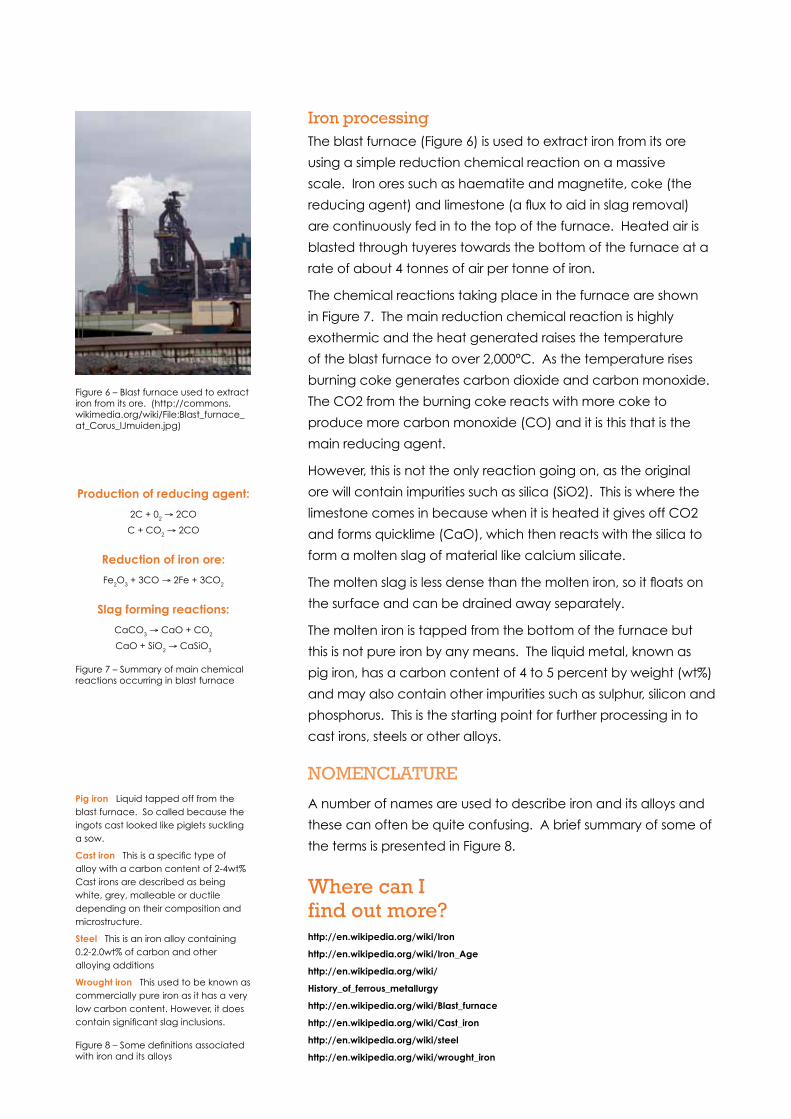
Iron processingThe blast furnace (Figure 6) is used to extract iron from its ore
using a simple reduction chemical reaction on a massive
scale. Iron ores such as haematite and magnetite, coke (the
reducing agent) and limestone (a flux to aid in slag removal)
are continuously fed in to the top of the furnace. Heated air is
blasted through tuyeres towards the bottom of the furnace at a
rate of about 4 tonnes of air per tonne of iron.
The chemical reactions taking place in the furnace are shown
in Figure 7. The main reduction chemical reaction is highly
exothermic and the heat generated raises the temperature
of the blast furnace to over 2,000°C. As the temperature rises
burning coke generates carbon dioxide and carbon monoxide.
The CO2 from the burning coke reacts with more coke to
produce more carbon monoxide (CO) and it is this that is the
main reducing agent.
However, this is not the only reaction going on, as the original
ore will contain impurities such as silica (SiO2). This is where the
limestone comes in because when it is heated it gives off CO2
and forms quicklime (CaO), which then reacts with the silica to
form a molten slag of material like calcium silicate.
The molten slag is less dense than the molten iron, so it floats on
the surface and can be drained away separately.
The molten iron is tapped from the bottom of the furnace but
this is not pure iron by any means. The liquid metal, known as
pig iron, has a carbon content of 4 to 5 percent by weight (wt%)
and may also contain other impurities such as sulphur, silicon and
phosphorus. This is the starting point for further processing in to
cast irons, steels or other alloys.
NOmENclaTURE
A number of names are used to describe iron and its alloys and
these can often be quite confusing. A brief summary of some of
the terms is presented in Figure 8.
Figure 6 – Blast furnace used to extract iron from its ore. (http://commons.wikimedia.org/wiki/File:Blast_furnace_at_Corus_IJmuiden.jpg)
Figure 7 – Summary of main chemical reactions occurring in blast furnace
Production of reducing agent:
2C + 02 → 2CO
C + CO2 → 2CO
Reduction of iron ore:
Fe2O3 + 3CO → 2Fe + 3CO2
Slag forming reactions:
CaCO3 → CaO + CO2
CaO + SiO2 → CaSiO3
Figure 8 – Some definitions associated with iron and its alloys
Pig iron Liquid tapped off from the blast furnace. So called because the ingots cast looked like piglets suckling a sow.
Cast iron This is a specific type of alloy with a carbon content of 2-4wt% Cast irons are described as being white, grey, malleable or ductile depending on their composition and microstructure.
Steel This is an iron alloy containing 0.2-2.0wt% of carbon and other alloying additions
Wrought iron This used to be known as commercially pure iron as it has a very low carbon content. However, it does contain significant slag inclusions.
Where can I find out more?http://en.wikipedia.org/wiki/Iron
http://en.wikipedia.org/wiki/Iron_Age
http://en.wikipedia.org/wiki/
History_of_ferrous_metallurgy
http://en.wikipedia.org/wiki/Blast_furnace
http://en.wikipedia.org/wiki/Cast_iron
http://en.wikipedia.org/wiki/steel
http://en.wikipedia.org/wiki/wrought_iron

Steel
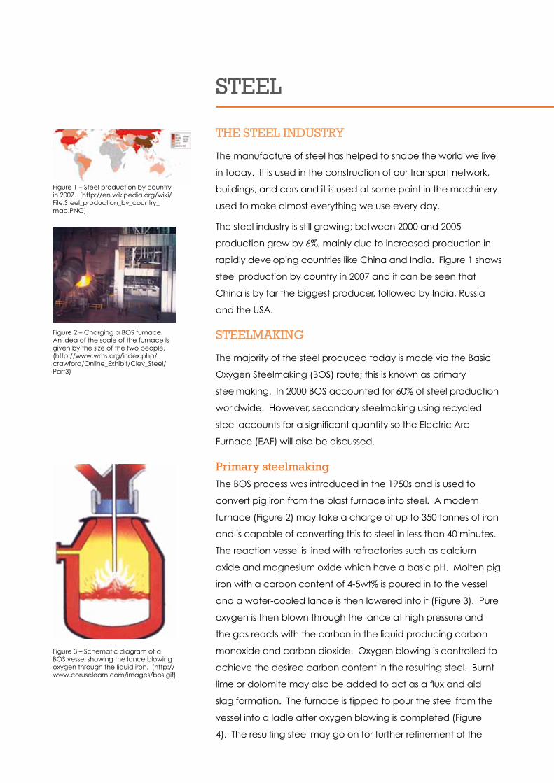
STEEl
THE STEEl INDUSTRY
The manufacture of steel has helped to shape the world we live
in today. It is used in the construction of our transport network,
buildings, and cars and it is used at some point in the machinery
used to make almost everything we use every day.
The steel industry is still growing; between 2000 and 2005
production grew by 6%, mainly due to increased production in
rapidly developing countries like China and India. Figure 1 shows
steel production by country in 2007 and it can be seen that
China is by far the biggest producer, followed by India, Russia
and the USA.
STEElmakING
The majority of the steel produced today is made via the Basic
Oxygen Steelmaking (BOS) route; this is known as primary
steelmaking. In 2000 BOS accounted for 60% of steel production
worldwide. However, secondary steelmaking using recycled
steel accounts for a significant quantity so the Electric Arc
Furnace (EAF) will also be discussed.
primary steelmakingThe BOS process was introduced in the 1950s and is used to
convert pig iron from the blast furnace into steel. A modern
furnace (Figure 2) may take a charge of up to 350 tonnes of iron
and is capable of converting this to steel in less than 40 minutes.
The reaction vessel is lined with refractories such as calcium
oxide and magnesium oxide which have a basic pH. Molten pig
iron with a carbon content of 4-5wt% is poured in to the vessel
and a water-cooled lance is then lowered into it (Figure 3). Pure
oxygen is then blown through the lance at high pressure and
the gas reacts with the carbon in the liquid producing carbon
monoxide and carbon dioxide. Oxygen blowing is controlled to
achieve the desired carbon content in the resulting steel. Burnt
lime or dolomite may also be added to act as a flux and aid
slag formation. The furnace is tipped to pour the steel from the
vessel into a ladle after oxygen blowing is completed (Figure
4). The resulting steel may go on for further refinement of the
Figure 1 – Steel production by country in 2007. (http://en.wikipedia.org/wiki/File:Steel_production_by_country_map.PNG)
Figure 2 – Charging a BOS furnace. An idea of the scale of the furnace is given by the size of the two people. (http://www.wrhs.org/index.php/crawford/Online_Exhibit/Clev_Steel/Part3)
Figure 3 – Schematic diagram of a BOS vessel showing the lance blowing oxygen through the liquid iron. (http://www.coruselearn.com/images/bos.gif)
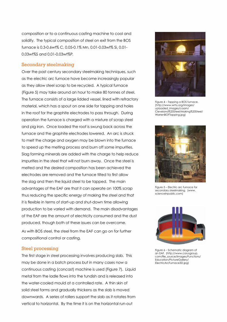
composition or to a continuous casting machine to cool and
solidify. The typical composition of steel on exit from the BOS
furnace is 0.3-0.6wt% C, 0.05-0.1% Mn, 0.01-0.03wt% Si, 0.01-
0.03wt%S and 0.01-0.03wt%P.
Secondary steelmakingOver the past century secondary steelmaking techniques, such
as the electric arc furnace have become increasingly popular
as they allow steel scrap to be recycled. A typical furnace
(Figure 5) may take around an hour to make 80 tonnes of steel.
The furnace consists of a large lidded vessel, lined with refractory
material, which has a spout on one side for tapping and holes
in the roof for the graphite electrodes to pass through. During
operation the furnace is charged with a mixture of scrap steel
and pig iron. Once loaded the roof is swung back across the
furnace and the graphite electrodes lowered. An arc is struck
to melt the charge and oxygen may be blown into the furnace
to speed up the melting process and burn off some impurities.
Slag forming minerals are added with the charge to help reduce
impurities in the steel that will not burn away. Once the steel is
melted and the desired composition has been achieved the
electrodes are removed and the furnace tilted to first allow
the slag and then the liquid steel to be tapped. The main
advantages of the EAF are that it can operate on 100% scrap
thus reducing the specific energy of making the steel and that
it is flexible in terms of start-up and shut-down time allowing
production to be varied with demand. The main disadvantages
of the EAF are the amount of electricity consumed and the dust
produced, though both of these issues can be overcome.
As with BOS steel, the steel from the EAF can go on for further
compositional control or casting.
Steel processingThe first stage in steel processing involves producing slab. This
may be done in a batch process but in many cases now a
continuous casting (concast) machine is used (Figure 7). Liquid
metal from the ladle flows into the tundish and is released into
the water-cooled mould at a controlled rate. A thin skin of
solid steel forms and gradually thickens as the slab is moved
downwards. A series of rollers support the slab as it rotates from
vertical to horizontal. By the time it is on the horizontal run-out
Figure 4 – Tapping a BOS furnace. (http://www.wrhs.org/images/uploaded_images/caam/Cleveland%20Steel/Making%20Steel/WarrenBOFTapping.jpg)
Figure 5 – Electric arc furnace for secondary steelmaking. (www.scienceinpublic.com)
Figure 6 – Schematic diagram of an EAF. (http://www.corusgroup.com/file_source/Images/Functions/Education/PictureGallery/ElectricArcFurnace3D.jpg)

table it is completely solid. A gas torch is used to cut the slab to
the desired length for subsequent processing.
The type of further processing will depend on the type of
product, but generally speaking processing can be split into two
types, which may be used in conjunction with each other:
1 HOT pROcESSING takes place above the recrystallisation
temperature of the material which for steel is typically
around 1000°C. Hot processing techniques include rolling
(Figure 8) and forging.
2 cOlD pROcESSING is defined as taking place below the
recrystallisation temperature of the material but this
generally means processing at room temperature.
Cold rolling is used to produce sheet or strip material
(Figure 9) and cold working can be used to strengthen a
material by introducing defects into the structure.
By employing these methods steel can be processed into a
wide variety of shapes and sizes and these plates, sheets, bars
and billets may be processed further by deep drawing, stretch
forming, bending and machining.
The steel may also undergo a heat treatment to modify the
structure and control the properties. The most common heat
treatments are:
aNNEalING. This involves heating the steel to above
its recrystallisation temperature and then allowing it to
cool slowly. A full annealing treatment has a very slow
cooling rate, and involves leaving the material in
the furnace to cool; a normalising treatment involves
air cooling which gives a slightly faster cooling
rate. Annealing relieves internal stresses in the steel and it
is used to soften and induce ductility in the material.
It may be carried out at regular intervals during a cold
forming process to make it easier to deform the material.
QUENcHING aND TEmpERING. This process is used to
harden the steel and involves heating it to a relatively
high temperature and then cooling it quickly by
quenching in oil, water or forced air. The rapid cooling
produces a hard, brittle non-equilibrium microstructure
Figure 7 – Schematic diagram showing the continuous casting process used to make steel slabs. (https://agora.cs.illinois.edu/download/attachments/20587553/cc.PNG)
Figure 8 – Hot rolling steel slab in a reversing mill. (http://web.srv.cmes.utah.edu:8080/metal/galleries/photo.2006-08-16.5298623956/variant/medium)
Figure 9 – Rolls of cold rolled strip steel. (http://www.nskamericas.com/cps/nsk/eu_en/p/images/content/CS_7003_ImageR_square_rdax_95.jpg)

which is then modified by tempering. A tempering
treatment involves heating to between 150°C and 700°C
which modifies the microstructure further and imparts
better toughness.
• caSE HaRDENING involves altering the surface
microstructure to make it harder than the core material.
It usually involves the diffusion of carbon and / or nitrogen
into the surface and the process is carried out at high
temperature to speed up the diffusion process.
STRUcTURE aND pROpERTIES OF STEEl
Steels are iron alloys containing between 0.2 and 2.0 percent
by weight of carbon and often a wide range of other elements.
Careful control of chemistry and processing conditions allows
the correct microstructure to be generated to give a steel with
the desired properties for the specific application.
Like iron, steels can adopt different crystal structures and the
thermal equilibrium diagram (Figure 10) for the iron-carbon
system can help us to understand how the structure changes
with both temperature and carbon content. The two most
important phases when discussing steels are austenite, a face-
centred cubic solid solution consisting of iron with up to 2wt%
of dissolved carbon and ferrite, a body centred cubic solid
solution containing up to 0.021wt% of dissolved carbon. These
two phases are both relatively soft and ductile with the former
generally existing at high temperature and the latter at room
temperature. If a steel containing between 0.021wt% and
0.8wt% of carbon is cooled from the austenite phase carbon
must precipitate out as the newly formed ferrite cannot hold
as much carbon in solution. The precipitate formed is the
intermetallic compound Fe3C which is known as cementite.
When alternating layers of ferrite and cementite are laid down
the structure is called pearlite. The microstructure of a slow-
cooled steel containing 0.1wt% carbon is shown in Figure 11.
If the steel contains between 0.8wt% and 2.0wt% carbon a
microstructure consisting of cementite and pearlite forms and
the microstructure of a steel containing 1.0wt% carbon is shown
in Figure 12.
Figure 10 – Thermal equilibrium diagram for the iron-carbon system. (http://thdick.co.uk/index.php/process/the_metallurgy_of_cast_iron)
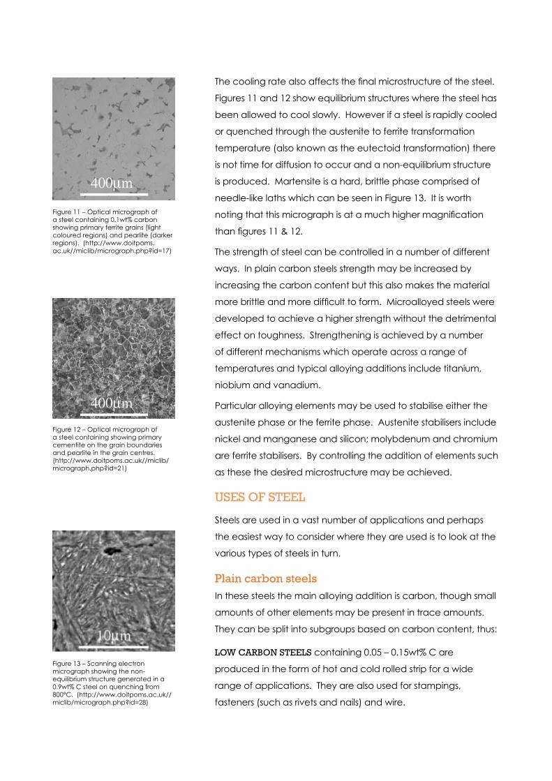
The cooling rate also affects the final microstructure of the steel.
Figures 11 and 12 show equilibrium structures where the steel has
been allowed to cool slowly. However if a steel is rapidly cooled
or quenched through the austenite to ferrite transformation
temperature (also known as the eutectoid transformation) there
is not time for diffusion to occur and a non-equilibrium structure
is produced. Martensite is a hard, brittle phase comprised of
needle-like laths which can be seen in Figure 13. It is worth
noting that this micrograph is at a much higher magnification
than figures 11 & 12.
The strength of steel can be controlled in a number of different
ways. In plain carbon steels strength may be increased by
increasing the carbon content but this also makes the material
more brittle and more difficult to form. Microalloyed steels were
developed to achieve a higher strength without the detrimental
effect on toughness. Strengthening is achieved by a number
of different mechanisms which operate across a range of
temperatures and typical alloying additions include titanium,
niobium and vanadium.
Particular alloying elements may be used to stabilise either the
austenite phase or the ferrite phase. Austenite stabilisers include
nickel and manganese and silicon; molybdenum and chromium
are ferrite stabilisers. By controlling the addition of elements such
as these the desired microstructure may be achieved.
USES OF STEEl
Steels are used in a vast number of applications and perhaps
the easiest way to consider where they are used is to look at the
various types of steels in turn.
plain carbon steelsIn these steels the main alloying addition is carbon, though small
amounts of other elements may be present in trace amounts.
They can be split into subgroups based on carbon content, thus:
lOW caRBON STEElS containing 0.05 – 0.15wt% C are
produced in the form of hot and cold rolled strip for a wide
range of applications. They are also used for stampings,
fasteners (such as rivets and nails) and wire.
Figure 11 – Optical micrograph of a steel containing 0.1wt% carbon showing primary ferrite grains (light coloured regions) and pearlite (darker regions). (http://www.doitpoms.ac.uk//miclib/micrograph.php?id=17)
Figure 12 – Optical micrograph of a steel containing showing primary cementite on the grain boundaries and pearlite in the grain centres. (http://www.doitpoms.ac.uk//miclib/micrograph.php?id=21)
Figure 13 – Scanning electron micrograph showing the non-equilibrium structure generated in a 0.9wt% C steel on quenching from 800°C. (http://www.doitpoms.ac.uk//miclib/micrograph.php?id=28)
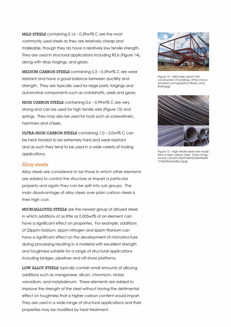
mIlD STEElS containing 0.16 – 0.29wt% C are the most
commonly used steels as they are relatively cheap and
malleable, though they do have a relatively low tensile strength.
They are used in structural applications including RSJs (Figure 14),
along with drop forgings, and gears.
mEDIUm caRBON STEElS containing 0.3 – 0.59wt% C are wear
resistant and have a good balance between ductility and
strength. They are typically used for large parts, forgings and
automotive components such as crankshafts, axels and gears.
HIGH caRBON STEElS containing 0.6 – 0.99wt% C are very
strong and can be used for high tensile wire (Figure 15) and
springs. They may also be used for tools such as screwdrivers,
hammers and chisels.
UlTRa-HIGH caRBON STEElS containing 1.0 – 2.0wt% C can
be heat treated to be extremely hard and wear resistant
and as such they tend to be used in a wide variety of tooling
applications.
alloy steelsAlloy steels are considered to be those in which other elements
are added to control the structure or impart a particular
property and again they can be split into sub groups. The
main disadvantage of alloy steels over plain carbon steels is
their high cost.
mIcROallOYED STEElS are the newest group of alloyed steels
in which additions of as little as 0.005wt% of an element can
have a significant effect on properties. For example, additions
of 23ppm niobium, 6ppm nitrogen and 6ppm titanium can
have a significant effect on the development of microstructure
during processing resulting in a material with excellent strength
and toughness suitable for a range of structural applications
including bridges, pipelines and off-shore platforms.
lOW allOY STEElS typically contain small amounts of alloying
additions such as manganese, silicon, chromium, nickel,
vanadium, and molybdenum. These elements are added to
improve the strength of the steel without having the detrimental
effect on toughness that a higher carbon content would impart.
They are used in a wide range of structural applications and their
properties may be modified by heat treatment.
Figure 14 – Mild steel used in the construction of buildings. (http://www.davisiron.com/graphics/Texas_Land_Bank.jpg)
Figure 15 – High tensile steel wire made from a high carbon steel. (http://imgs.tootoo.com/07/24/0724bf2225bf066307cf3e3b6adc86c3.jpg)

HIGHlY allOYED STEElS typically contain alloying additions in
quantities greater than 5% and in this case particular elements
are chosen to impart particular properties such as corrosion
resistance (chromium and nickel added to give stainless steels)
or wear resistance (tungsten, molybdenum or cobalt added to
make high speed steels).
SUmmaRY
Steels continue to play a vital role in our society and the broad
range of materials available, both in terms of properties and cost,
means that there is usually a steel capable of doing the job.
Where can I find out more?http://en.wikipedia.org/wiki/Steel
http://en.wikipedia.org/wiki/Steelmaking
http://en.wikipedia.org/wiki/Basic_oxygen_steelmaking
http://en.wikipedia.org/wiki/Electric_arc_furnace
http://www.steeluniversity.org
http://www.wrhs.org/index.php/crawford/Online_Exhibit/Clev_Steel/Part3
http://resources.schoolscience.co.uk/Corus/11-14/index.html
http://resources.schoolscience.co.uk/corus/14-16/steel/index.html
http://en.wikipedia.org/wiki/Continuous_casting
http://www.calphad.com/iron-carbon.html
http://en.wikipedia.org/wiki/Heat_treatment
http://en.wikipedia.org/wiki/Carbon_steels
http://en.wikipedia.org/wiki/Alloy_steel


