
Neither the whole nor any part of the information contained in, or the product described in this manual, may be adapted or
reproduced in any material or electronic form without the prior written consent of the copyright holder. This product and its
documentation are supplied on an as-is basis and no warranty as to their suitability for any particular purpose is either made or
implied. Bridgetek Pte Ltd will not accept any claim for damages howsoever arising as a result of use or failure of this product.
Your statutory rights are not affected. This product or any variant of it is not intended for use in any medical appliance, device or
system in which the failure of the product might reasonably be expected to result in personal injury. This document provides
preliminary information that may be subject to change without notice. No freedom to use patents or other intellectual property
rights is implied by the publication of this document. Bridgetek Pte Ltd, 178 Paya Lebar Road, #07-03, Singapore 409030.
Singapore Registered Company Number: 201542387H
Copyright © Bridgetek Pte Ltd 1
CleOIO-Shield Module Datasheet
Version 1.1
Document Reference No.: BRT_000080 Clearance No.: BRT#066
Bridgetek Pte Ltd
CleOIO-Shield Module
Datasheet
1 Introduction
The CleOIO-Shield is an input/output expansion shield for CleO series and belongs to CleO
accessories. It is compatible with CleO35, CleO50, NerO, providing easy and extended I/O for Analog, Digital, I2C, SPI, UART interface. I/O features can be connected through Arduino Uno interface, MikroBus header, and Grove-Universal 4pin connector.
The CleOIO-Shield is supplied with 5 daughter boards, One 4pin to 2pinx2 speaker cable.
1.1 Features
Arduino Uno compatible
CleO35, CleO50, NerO compatible
With RTC module including external battery
switch over function
With FM radio module including CleO Speaker output and headphone Audio Jack output
With Voltmeter module up to 20V measurement
With 5 daughter boards as bundle: rotary potentiometers module, temperature &
humidity sensor module, light sensor (LDR) module, microphone (MIC) module
Contains 3.3V & 5.0V jumper selection
Hardware reset button provided
DC power input jack for 7V-20VDC 1A power adapter, 9VDC or 12VDC recommended
Support Analog & Digital I/O
Support I2C, SPI, UART interface
Support MikroBUS interface*
CE and FCC certified**
*MikroBus interface is created by MikroElektronika as an open standard anyone can implement in their design. Please visit MikroE for more details
**FM function not tested under EN55020

Copyright © Bridgetek Pte Ltd 2
CleOIO-Shield Module Datasheet Version 1.1
Document Reference No.: BRT_000080 Clearance No.: BRT#066
2 Ordering Information
Part No. Description
CleOIO-Shield1 CleOIO-Shield1 module, with 5 daughter board modules, one 4pin to 2pinx2
speaker cable.
3 Program Support
Demo applications are provided for CleO modules by Bridgetek. Visit http://brtchip.com/m-cleo/ for more information.

Copyright © Bridgetek Pte Ltd 3
CleOIO-Shield Module Datasheet Version 1.1
Document Reference No.: BRT_000080 Clearance No.: BRT#066
Table of Contents
1 Introduction .................................................................... 1
1.1 Features .................................................................................... 1
2 Ordering Information ...................................................... 2
3 Program Support ............................................................. 2
4 Module Hardware Feature ............................................... 4
4.1 Power Supply ............................................................................ 5
4.2 Extended I/O Port .................................................................... 5
4.3 FM Radio Module ..................................................................... 11
4.4 Real Time Clock (RTC) Module ................................................ 11
4.5 Voltmeter Module .................................................................... 11
4.6 Rotary Potentiometer Module ................................................. 12
4.7 Microphone (MIC) Module ....................................................... 12
4.8 Temperature and Humidity Sensor Module ............................. 13
4.9 Light Sensor (LDR) Module ..................................................... 13
5 Devices Characteristics and Ratings .............................. 14
5.1 Electrical Specification ............................................................ 14
6 Board Schematics .......................................................... 15
7 Mechanical Dimensions ................................................. 17
7.1 CleOIO-Shield Main Board Dimensions .................................... 17
7.2 Daughter Boards Dimensions .................................................. 18
8 Contact Information ...................................................... 19
Appendix A – References ................................................... 20
Document References ..................................................................... 20
Acronyms and Abbreviations ........................................................... 20
Appendix B - List of Figures and Tables ............................. 21
List of Tables ................................................................................... 21
List of Figures ................................................................................. 21
Appendix C – Revision History ........................................... 22

Copyright © Bridgetek Pte Ltd 4
CleOIO-Shield Module Datasheet Version 1.1
Document Reference No.: BRT_000080 Clearance No.: BRT#066
4 Module Hardware Feature
The dimensions of the CleOIO-Shield main board are 70 mm x 53 mm x 21 mm. See Figures for all the hardware features.
Figure 1 – CleOIO-Shield Top View
Figure 2 – Five Daughter Modules Top View
Key Features:
1 Voltmeter module 2 FM radio audio output
3 FM radio headphone jack 4 DC power jack
5 Reset button 6 Arduino I/F
7 3.3V & 5.0V jumper selection 8 Grove – Universal 4pin connector
9 FM radio module 10 MikroBUS headers
1
2
3
4
5 9 6 6
8
12
10
8
6 6 7 7
11
10
13 13 14 16 15

Copyright © Bridgetek Pte Ltd 5
CleOIO-Shield Module Datasheet Version 1.1
Document Reference No.: BRT_000080 Clearance No.: BRT#066
4.1 Power Supply
The CleOIO-Shield receives power externally. Power can either be drawn from external source through DC power jack or power pins (+3V3 and +5V) of CN2.
Figure 3 – Power Supply
4.2 Extended I/O Port
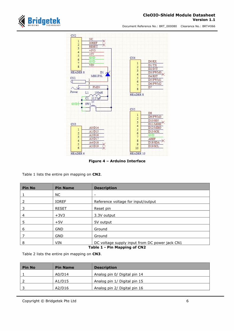
The CleOIO-Shield board contains extended I/O ports for user’s convenience. Arduino interface headers CN2, CN3, CN4, CN5 enable easy-access to many Arduino shields. MikroBUS headers CN6, CN7 are compatible to popular ClickTM boards for fast prototyping. Grove – Universal 4pin connectors are also ready for user to connect various simple application modules, with the jumper option on 3.3V or 5.0V voltage supply.
Arduino interface headers:
11 RTC module 12 Battery holder
13 Rotary Potentiometer module
15 Temperature & Humidity Sensor module
14 Light Sensor (LDR) module
16 Microphone (MIC) module
Copyright © Bridgetek Pte Ltd 6
CleOIO-Shield Module Datasheet Version 1.1
Document Reference No.: BRT_000080 Clearance No.: BRT#066
Figure 4 – Arduino Interface
Table 1 lists the entire pin mapping on CN2.
Pin No Pin Name Description
1 NC -
2 IOREF Reference voltage for input/output
3 RESET Reset pin
4 +3V3 3.3V output
5 +5V 5V output
6 GND Ground
7 GND Ground
8 VIN DC voltage supply input from DC power jack CN1
Table 1 - Pin Mapping of CN2
Table 2 lists the entire pin mapping on CN3.
Pin No Pin Name Description
1 A0/D14 Analog pin 0/ Digital pin 14
2 A1/D15 Analog pin 1/ Digital pin 15
3 A2/D16 Analog pin 2/ Digital pin 16
Copyright © Bridgetek Pte Ltd 7
CleOIO-Shield Module Datasheet Version 1.1
Document Reference No.: BRT_000080 Clearance No.: BRT#066
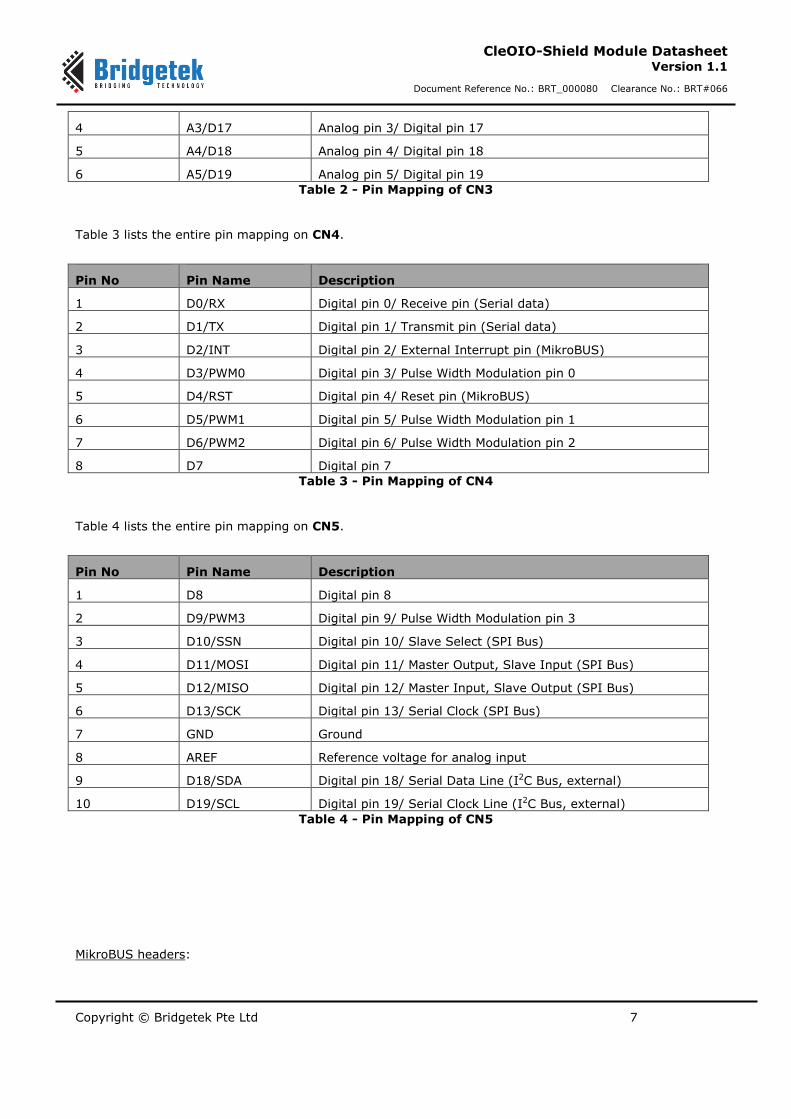
4 A3/D17 Analog pin 3/ Digital pin 17
5 A4/D18 Analog pin 4/ Digital pin 18
6 A5/D19 Analog pin 5/ Digital pin 19
Table 2 - Pin Mapping of CN3
Table 3 lists the entire pin mapping on CN4.
Pin No Pin Name Description
1 D0/RX Digital pin 0/ Receive pin (Serial data)
2 D1/TX Digital pin 1/ Transmit pin (Serial data)
3 D2/INT Digital pin 2/ External Interrupt pin (MikroBUS)
4 D3/PWM0 Digital pin 3/ Pulse Width Modulation pin 0
5 D4/RST Digital pin 4/ Reset pin (MikroBUS)
6 D5/PWM1 Digital pin 5/ Pulse Width Modulation pin 1
7 D6/PWM2 Digital pin 6/ Pulse Width Modulation pin 2
8 D7 Digital pin 7
Table 3 - Pin Mapping of CN4
Table 4 lists the entire pin mapping on CN5.
Pin No Pin Name Description
1 D8 Digital pin 8
2 D9/PWM3 Digital pin 9/ Pulse Width Modulation pin 3
3 D10/SSN Digital pin 10/ Slave Select (SPI Bus)
4 D11/MOSI Digital pin 11/ Master Output, Slave Input (SPI Bus)
5 D12/MISO Digital pin 12/ Master Input, Slave Output (SPI Bus)
6 D13/SCK Digital pin 13/ Serial Clock (SPI Bus)
7 GND Ground
8 AREF Reference voltage for analog input
9 D18/SDA Digital pin 18/ Serial Data Line (I2C Bus, external)
10 D19/SCL Digital pin 19/ Serial Clock Line (I2C Bus, external)
Table 4 - Pin Mapping of CN5
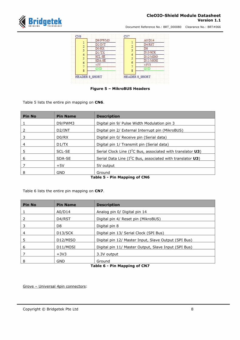
MikroBUS headers:
Copyright © Bridgetek Pte Ltd 8
CleOIO-Shield Module Datasheet Version 1.1
Document Reference No.: BRT_000080 Clearance No.: BRT#066
Figure 5 – MikroBUS Headers
Table 5 lists the entire pin mapping on CN6.
Pin No Pin Name Description
1 D9/PWM3 Digital pin 9/ Pulse Width Modulation pin 3
2 D2/INT Digital pin 2/ External Interrupt pin (MikroBUS)
3 D0/RX Digital pin 0/ Receive pin (Serial data)
4 D1/TX Digital pin 1/ Transmit pin (Serial data)
5 SCL-SE Serial Clock Line (I2C Bus, associated with translator U3)
6 SDA-SE Serial Data Line (I2C Bus, associated with translator U3)
7 +5V 5V output
8 GND Ground
Table 5 - Pin Mapping of CN6
Table 6 lists the entire pin mapping on CN7.
Pin No Pin Name Description
1 A0/D14 Analog pin 0/ Digital pin 14
2 D4/RST Digital pin 4/ Reset pin (MikroBUS)
3 D8 Digital pin 8
4 D13/SCK Digital pin 13/ Serial Clock (SPI Bus)
5 D12/MISO Digital pin 12/ Master Input, Slave Output (SPI Bus)
6 D11/MOSI Digital pin 11/ Master Output, Slave Input (SPI Bus)
7 +3V3 3.3V output
8 GND Ground
Table 6 - Pin Mapping of CN7
Grove – Universal 4pin connectors:

Copyright © Bridgetek Pte Ltd 9
CleOIO-Shield Module Datasheet Version 1.1
Document Reference No.: BRT_000080 Clearance No.: BRT#066
Figure 6 – Grove-Universal 4pin Connectors
Table 7 lists the entire pin mapping on CN11.
Pin No Pin Name Description
1 GND Ground
2 VDD11 3.3V or 5.0V Supplied Voltage for CN11
3 A1/D15 Analog pin 1/ Digital pin 15
4 A0/D14 Analog pin 0/ Digital pin 14
Table 7 - Pin Mapping of CN11
Table 8 lists the entire pin mapping on CN12.
Pin No Pin Name Description
1 GND Ground
2 VDD12 3.3V or 5.0V Supplied Voltage for CN12
3 A3/D17 Analog pin 3/ Digital pin 17
4 A2/D16 Analog pin 2/ Digital pin 16
Table 8 - Pin Mapping of CN12
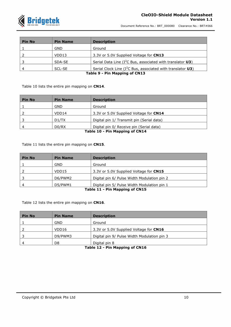
Table 9 lists the entire pin mapping on CN13.
Copyright © Bridgetek Pte Ltd 10
CleOIO-Shield Module Datasheet Version 1.1
Document Reference No.: BRT_000080 Clearance No.: BRT#066
Pin No Pin Name Description
1 GND Ground
2 VDD13 3.3V or 5.0V Supplied Voltage for CN13
3 SDA-SE Serial Data Line (I2C Bus, associated with translator U3)
4 SCL-SE Serial Clock Line (I2C Bus, associated with translator U3)
Table 9 - Pin Mapping of CN13
Table 10 lists the entire pin mapping on CN14.
Pin No Pin Name Description
1 GND Ground
2 VDD14 3.3V or 5.0V Supplied Voltage for CN14
3 D1/TX Digital pin 1/ Transmit pin (Serial data)
4 D0/RX Digital pin 0/ Receive pin (Serial data)
Table 10 - Pin Mapping of CN14
Table 11 lists the entire pin mapping on CN15.
Pin No Pin Name Description
1 GND Ground
2 VDD15 3.3V or 5.0V Supplied Voltage for CN15
3 D6/PWM2 Digital pin 6/ Pulse Width Modulation pin 2
4 D5/PWM1 Digital pin 5/ Pulse Width Modulation pin 1
Table 11 - Pin Mapping of CN15
Table 12 lists the entire pin mapping on CN16.
Pin No Pin Name Description
1 GND Ground
2 VDD16 3.3V or 5.0V Supplied Voltage for CN16
3 D9/PWM3 Digital pin 9/ Pulse Width Modulation pin 3
4 D8 Digital pin 8
Table 12 - Pin Mapping of CN16

Copyright © Bridgetek Pte Ltd 11
CleOIO-Shield Module Datasheet Version 1.1
Document Reference No.: BRT_000080 Clearance No.: BRT#066
4.3 FM Radio Module
The CleOIO-Shield contains FM radio module with support frequency range 50MHz to 115MHz. The FM radio module is connected using the I2C interface through a voltage translator IC U2
(FXMAR2102UMX_F106), which allows different voltage translation (3.3V or 5.0V) between master and slave. The FM radio module is connected with either headphone jack CN8 for stereo audio output or speaker port CN9 for mono audio output. User may connect an earpiece cable to headphone jack CN8 or a DC power cord to DC power jack CN1 to work as antenna for the FM radio module.
Figure 7 – FM Module
4.4 Real Time Clock (RTC) Module
The CleOIO-Shield contains RTC circuitry. The RTC is connected using I2C interface through a voltage translator IC U2 (FXMAR2102UMX_F106), which allows different voltage translation (3.3V or 5.0V) between master and slave. The RTC can be powered by 3V 12.5mm backup Lithium coin battery (CR-
1220) during off-mode.
Figure 8 – RTC Module
4.5 Voltmeter Module
Voltmeter module with 4position terminal block allows user to carry out voltage measurement up to 5V,
10V and 20V. Measured voltage result is transmitted through terminal block pin 2 by jumper setting to analog A3 pin of Arduino I/F.
Copyright © Bridgetek Pte Ltd 12
CleOIO-Shield Module Datasheet Version 1.1
Document Reference No.: BRT_000080 Clearance No.: BRT#066
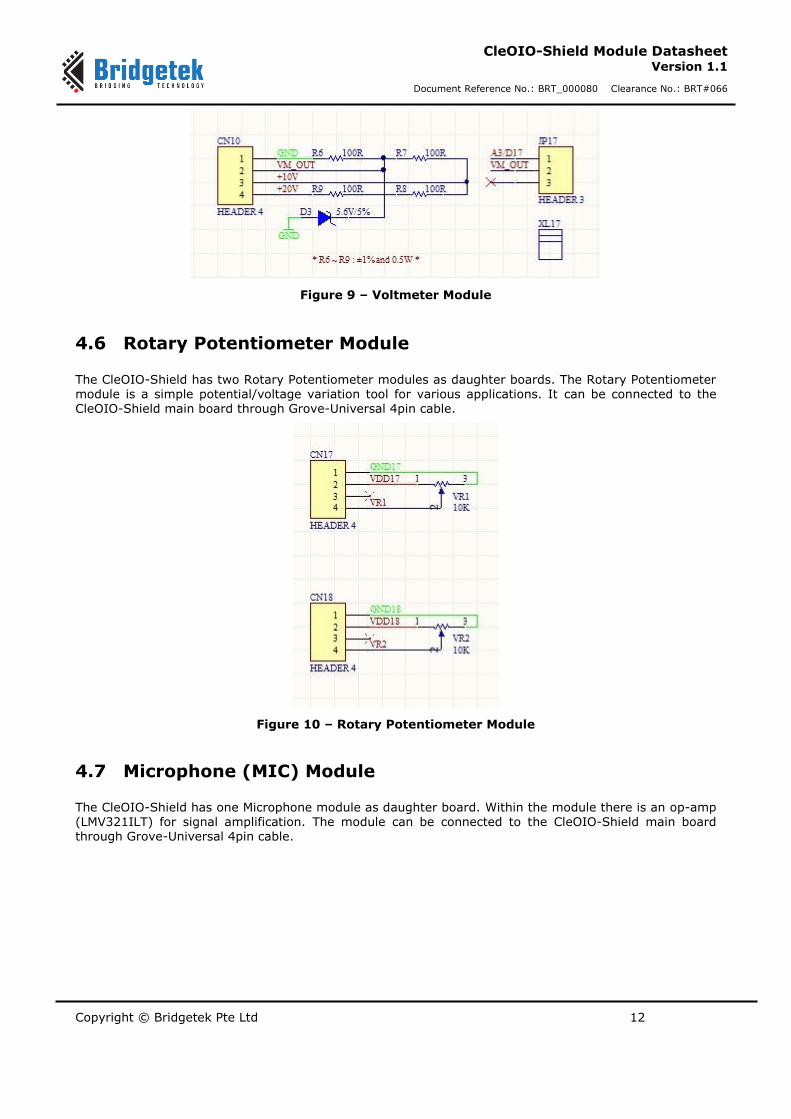
Figure 9 – Voltmeter Module
4.6 Rotary Potentiometer Module
The CleOIO-Shield has two Rotary Potentiometer modules as daughter boards. The Rotary Potentiometer module is a simple potential/voltage variation tool for various applications. It can be connected to the CleOIO-Shield main board through Grove-Universal 4pin cable.
Figure 10 – Rotary Potentiometer Module
4.7 Microphone (MIC) Module
The CleOIO-Shield has one Microphone module as daughter board. Within the module there is an op-amp (LMV321ILT) for signal amplification. The module can be connected to the CleOIO-Shield main board through Grove-Universal 4pin cable.
Copyright © Bridgetek Pte Ltd 13
CleOIO-Shield Module Datasheet Version 1.1
Document Reference No.: BRT_000080 Clearance No.: BRT#066
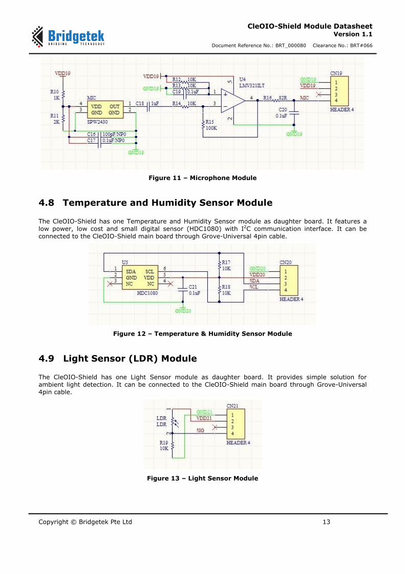
Figure 11 – Microphone Module
4.8 Temperature and Humidity Sensor Module
The CleOIO-Shield has one Temperature and Humidity Sensor module as daughter board. It features a low power, low cost and small digital sensor (HDC1080) with I2C communication interface. It can be connected to the CleOIO-Shield main board through Grove-Universal 4pin cable.
Figure 12 – Temperature & Humidity Sensor Module
4.9 Light Sensor (LDR) Module
The CleOIO-Shield has one Light Sensor module as daughter board. It provides simple solution for ambient light detection. It can be connected to the CleOIO-Shield main board through Grove-Universal 4pin cable.
Figure 13 – Light Sensor Module

Copyright © Bridgetek Pte Ltd 14
CleOIO-Shield Module Datasheet Version 1.1
Document Reference No.: BRT_000080 Clearance No.: BRT#066
5 Devices Characteristics and Ratings
5.1 Electrical Specification
Parameter Value Unit Conditions
Storage Temperature -30°C to 80°C Degrees C
Ambient Operating Temperature (Power Applied)
-20°C to 70°C Degrees C
Table 13 - Temperature Parameter
DC Characteristics (Ambient Temperature = -20°C to +70°C)
Parameter Description Minimum Typical Maximum Units Conditions
VDC DC Power Supply 7 9,12 20 V External source
from NerO
IDC DC Supply Current 1 A External source
from NerO
Vio 5.0 Vio Voltage
Reference 4.75 5.25 V
Vio 3.3 Vio Voltage
Reference 3.0 3.6 V
Iio Max current draw
from IO pin 25 mA
Table 14 - Operating Voltage and Current

Copyright © Bridgetek Pte Ltd 15
CleOIO-Shield Module Datasheet Version 1.1
Document Reference No.: BRT_000080 Clearance No.: BRT#066
6 Board Schematics
Figure 14 – Sheet 1 – CleOIO-Shield Main Board
Copyright © Bridgetek Pte Ltd 16
CleOIO-Shield Module Datasheet Version 1.1
Document Reference No.: BRT_000080 Clearance No.: BRT#066
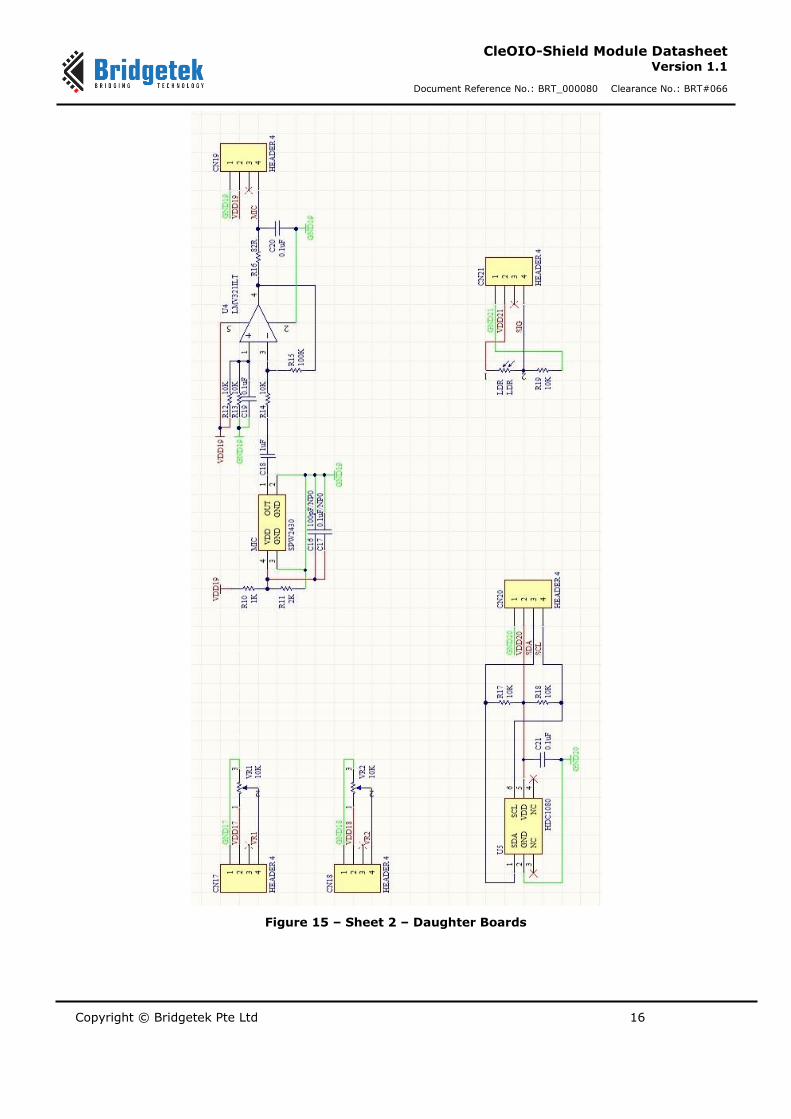
Figure 15 – Sheet 2 – Daughter Boards

Copyright © Bridgetek Pte Ltd 17
CleOIO-Shield Module Datasheet Version 1.1
Document Reference No.: BRT_000080 Clearance No.: BRT#066
7 Mechanical Dimensions
7.1 CleOIO-Shield Main Board Dimensions
Figure 16 – CleOIO-Shield Main Board Dimensions
70.0mm
53.3mm
21.0mm

Copyright © Bridgetek Pte Ltd 18
CleOIO-Shield Module Datasheet Version 1.1
Document Reference No.: BRT_000080 Clearance No.: BRT#066
7.2 Daughter Boards Dimensions
Figure 17 – Daughter Boards Dimensions
24.1mm
20.3mm
29.6mm

Copyright © Bridgetek Pte Ltd 19
CleOIO-Shield Module Datasheet Version 1.1
Document Reference No.: BRT_000080 Clearance No.: BRT#066
8 Contact Information
Headquarters – Singapore Branch Office – Taipei, Taiwan
Bridgetek Pte Ltd 178 Paya Lebar Road, #07-03 Singapore 409030 Tel: +65 6547 4827 Fax: +65 6841 6071
Bridgetek Pte Ltd, Taiwan Branch 2 Floor, No. 516, Sec. 1, Nei Hu Road, Nei Hu District Taipei 114 Taiwan, R.O.C. Tel: +886 (2) 8797 5691
Fax: +886 (2) 8751 9737 E-mail (Sales) [email protected] E-mail (Sales) [email protected] E-mail (Support) [email protected] E-mail (Support) [email protected]
Branch Office - Glasgow, United Kingdom Branch Office – Vietnam
Bridgetek Pte. Ltd. Unit 1, 2 Seaward Place, Centurion Business Park Glasgow G41 1HH United Kingdom Tel: +44 (0) 141 429 2777 Fax: +44 (0) 141 429 2758
Bridgetek VietNam Company Limited Lutaco Tower Building, 5th Floor, 173A Nguyen Van Troi, Ward 11, Phu Nhuan District, Ho Chi Minh City, Vietnam Tel : 08 38453222 Fax : 08 38455222
E-mail (Sales) [email protected] E-mail (Sales) [email protected] E-mail (Support) [email protected] E-mail (Support) [email protected]
Web Site
http://brtchip.com/
Distributor and Sales Representatives
Please visit the Sales Network page of the Bridgetek website for the contact details of our distributor(s) and sales
representative(s) in your country.
System and equipment manufacturers and designers are responsible to ensure that their systems, and any Bridgetek Pte Ltd (BRT Chip) devices
incorporated in their systems, meet all applicable safety, regulatory and system-level performance requirements. All application-related
information in this document (including application descriptions, suggested Bridgetek devices and other materials) is provided for reference only.
While Bridgetek has taken care to assure it is accurate, this information is subject to customer confirmation, and Bridgetek disclaims all liability
for system designs and for any applications assistance provided by Bridgetek. Use of Bridgetek devices in life support and/or safety applications is
entirely at the user’s risk, and the user agrees to defend, indemnify and hold harmless Bridgetek from any and all damages, c laims, suits or expense resulting from such use. This document is subject to change without notice. No freedom to use patents or other intellectual property
rights is implied by the publication of this document. Neither the whole nor any part of the information contained in, or the product described in
this document, may be adapted or reproduced in any material or electronic form without the prior written consent of the copyright holder.
Bridgetek Pte Ltd, 178 Paya Lebar Road, #07-03, Singapore 409030. Singapore Registered Company Number: 201542387H.

Copyright © Bridgetek Pte Ltd 20
CleOIO-Shield Module Datasheet Version 1.1
Document Reference No.: BRT_000080 Clearance No.: BRT#066
Appendix A – References
Document References
For module documentations, please refer to URL below:
FM Radio RDA5807M datasheet: FM Radio RDA5807M datasheet
RTC PCF8523 datasheet: RTC PCF8523 datasheet
Temperature & Humidity sensor HDC1080 datasheet : Temperature & Humidity Sensor HDC1080 datasheet
Microphone SPW2430HR5H-B datasheet: Microphone SPW2430HR5H-B datasheet
Light sensor HW5P-1 datasheet: Light sensor HW5P-1 datasheet
mikroBus: http://www.mikroe.com/mikrobus/
Arduino: https://www.arduino.cc/
CleO Product Page: http://brtchip.com/m-cleo/
CleO Resources: CleOstuff
Acronyms and Abbreviations
Terms Description
DC Direct Current
FM Frequency Modulation
IC Integrated Circuit
I/F Interface
I/O Input/output
I2C Inter-Integrated Circuit
LDR Light Dependent Resistor
MIC Microphone
RTC Real Time Clock
SPI Serial Peripheral Interface
UART Universal Asynchronous Receiver/Transmitter

Copyright © Bridgetek Pte Ltd 21
CleOIO-Shield Module Datasheet Version 1.1
Document Reference No.: BRT_000080 Clearance No.: BRT#066
Appendix B - List of Figures and Tables
List of Tables
Table 1 - Pin Mapping of CN2 ......................................................................................................... 6
Table 2 - Pin Mapping of CN3 ......................................................................................................... 7
Table 3 - Pin Mapping of CN4 ......................................................................................................... 7
Table 4 - Pin Mapping of CN5 ......................................................................................................... 7
Table 5 - Pin Mapping of CN6 ......................................................................................................... 8
Table 6 - Pin Mapping of CN7 ......................................................................................................... 8
Table 7 - Pin Mapping of CN11 ....................................................................................................... 9
Table 8 - Pin Mapping of CN12 ....................................................................................................... 9
Table 9 - Pin Mapping of CN13 ..................................................................................................... 10
Table 10 - Pin Mapping of CN14 ................................................................................................... 10
Table 11 - Pin Mapping of CN15 ................................................................................................... 10
Table 12 - Pin Mapping of CN16 ................................................................................................... 10
Table 13 - Temperature Parameter ............................................................................................... 14
Table 14 - Operating Voltage and Current...................................................................................... 14
List of Figures
Figure 1 – CleOIO-Shield Top View ................................................................................................. 4
Figure 2 – Five Daughter Modules Top View ..................................................................................... 4
Figure 3 – Power Supply ................................................................................................................ 5
Figure 4 – Arduino Interface .......................................................................................................... 6
Figure 5 – MikroBUS Headers ......................................................................................................... 8
Figure 6 – Grove-Universal 4pin Connectors .................................................................................... 9
Figure 7 – FM Module .................................................................................................................. 11
Figure 8 – RTC Module ................................................................................................................ 11
Figure 9 – Voltmeter Module ........................................................................................................ 12
Figure 10 – Rotary Potentiometer Module ...................................................................................... 12
Figure 11 – Microphone Module .................................................................................................... 13
Figure 12 – Temperature & Humidity Sensor Module ....................................................................... 13
Figure 13 – Light Sensor Module .................................................................................................. 13
Figure 14 – Sheet 1 – CleOIO-Shield Main Board ............................................................................ 15
Figure 15 – Sheet 2 – Daughter Boards ......................................................................................... 16
Figure 16 – CleOIO-Shield Main Board Dimensions ......................................................................... 17
Figure 17 – Daughter Boards Dimensions ...................................................................................... 18

Copyright © Bridgetek Pte Ltd 22
CleOIO-Shield Module Datasheet Version 1.1
Document Reference No.: BRT_000080 Clearance No.: BRT#066
Appendix C – Revision History
Document Title: CleOIO-Shield Module Datasheet
Document Reference No.: BRT_000080
Clearance No.: BRT#066
Product Page: http://brtchip.com/m-cleo/
Document Feedback: Send Feedback
Revision Changes Date
Version 1.0 Initial Release 2017-03-02
Version 1.1 Updated the CleOIO-Shield pictures with latest version
2017-05-16


