
COMBUSTION AND FUELS
BURNING IN
BOILER FURNACES

COMBUSTION AND FUELS
FURNACES
COMBUSTION AND FUELS
Boiler furnace tasks
The most important task of the boiler furnace is to provide conditions for proper combustion of fuel which is achived by:
1. Fuel supply of the boiler furnace at the required rate
and keeping it in the furnace by the time sufficient for
burnt out.
2. Air supply of the boiler furnace at the required rate and
proper mixing with the fuel.

COMBUSTION AND FUELS
Types of boiler furnaces
Coal-fired boilers can be classified regarding the type of a furnace:
� grate boilers (stoker),
� pulverized fuel-fired boilers (PF),
� fluidized-bed boilers.

COMBUSTION AND FUELS
TRAVELLING GRATE
FURNACES
COMBUSTION AND FUELS
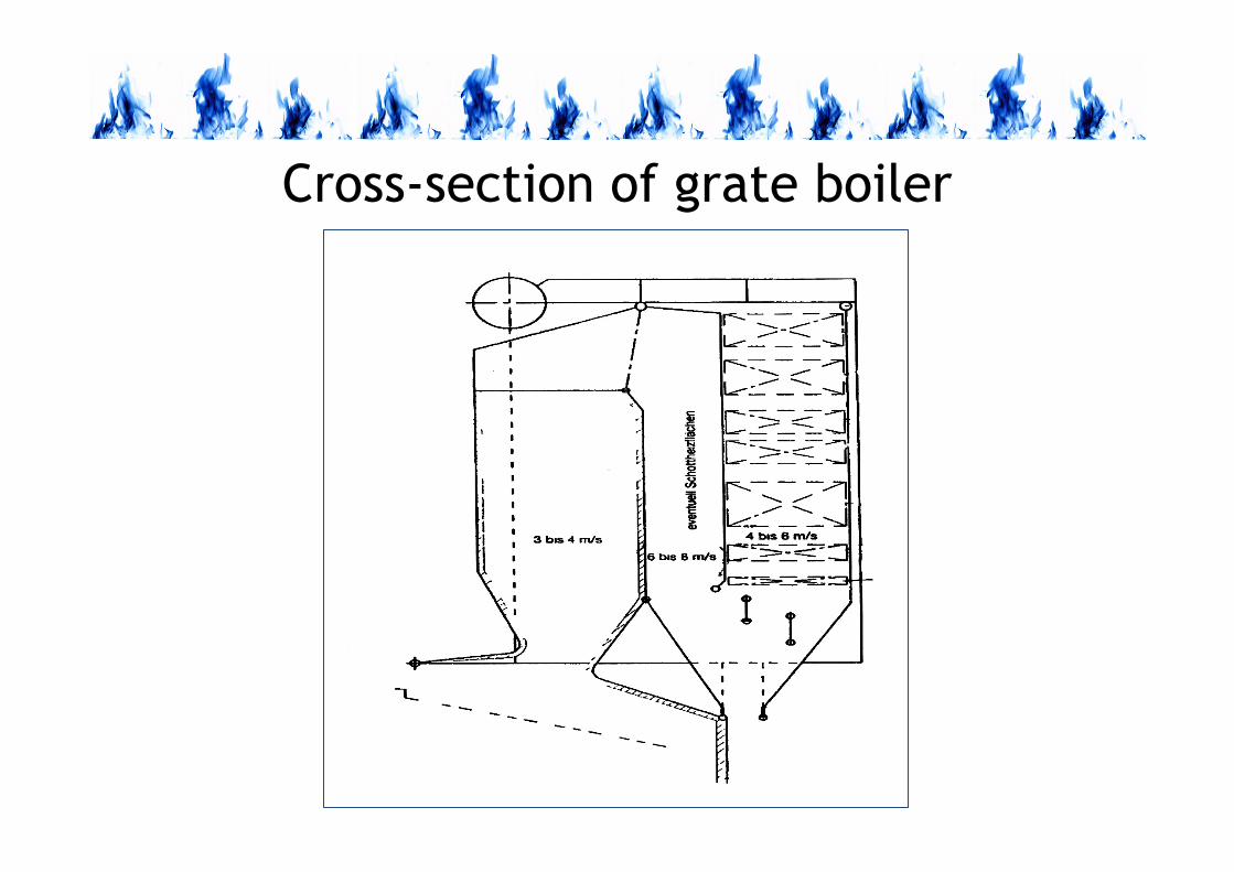
Cross-section of grate boiler

COMBUSTION AND FUELS
Burning on the travelling grate
Zones of combustion
1 – drying,
2 – devolatilization,
3 – burning,
4 – ash
Boilers of capacity up to 60 t/h usually are stokers.
required air

COMBUSTION AND FUELS
Zones of combustion on grate
drying burning cooling
secondary airgas
primary air
vaporizationmoisture removal
drying zone
combustion zone
agglomeration zone

Example of coal-fired stoker
WR 25
RAFAKO SA
Distribution
of air under
grate

COMBUSTION AND FUELS
Ignition vault of the grate furnace
Mechanism of coal layer ignition by the furnace vault
Flame
Moving grate
Ignition
vault

COMBUSTION AND FUELS
Coal-burning on grate
OR 32
RAFAKO SAFlame

COMBUSTION AND FUELS
RETORT FURNACES

COMBUSTION AND FUELS
Principle of retort furnace operation
Worm-gear feederAir box

COMBUSTION AND FUELS
Burning in retort furnace

ash pan
retort
air box
heat exchanger
flue
fuel reservoir
screw feeder
air fan
Boiler with retort furnace

COMBUSTION AND FUELS
Retort furnace

COMBUSTION AND FUELS
PULVERIZED COAL FURNACES

Steam pulverized coal-fired boiler
Pulverized coal-fired boiler of capacity 650 t/h with tangential furnace

COMBUSTION AND FUELS
Modern pulverized coal-fired boilers
In modern power plants pulverized coal-fired
boilers have mainly furnaces with membrane
walls and major heat transfer is due to
radiation.

COMBUSTION AND FUELS
Some technical data related to pulverized coal burning
Fuel burned in a furnace: pulverized coal (pc)
Delivery of pc to a furnace: by pulverized coal burners
Transport of pc to a burner: pneumatic, in flowing gas
(hot air, flue gas)
Pulverized coal concentration on gas:
- hard coal: 0.5 kg/m3
- lignite: 0.2-0.3 kg/m3

COMBUSTION AND FUELS
Phases of pulverized coal burning
The time of pulverized coal-air mixture in a furnace can be divided
into three periods:
1. drying, devolatilization and ignition of coal particles, which
requires 0.2–0.3 s,
2. Intensive mixing and burning of pulverized coal-air jet during
0.5–1.5 s on a distance of 1–5 m with formation of flame kernel
of the temperature 1500–1600 °C,
3. Burnout of larger coal particles and cooling of flue gas during
1–3 s on a distance 2/3 of the furnace.

COMBUSTION AND FUELS
Types of pulverized coal-fired furnaces
The main criteria is location of burners:
• wall-fired furnaces,
• roof-fired furnaces,
• corner-fired furnaces (tangentially fired).

COMBUSTION AND FUELS
Geometry of boiler furnaces
Pulverized coal-fired furnaces:
a) wall-fired, b) roof-fired, c) corner-fired

COMBUSTION AND FUELS
Combustion systems of
pulverized coal-fired boilers
• wall-fired furnaces with swirl burners (located
at the front, back or side wall of the furnace)
• corner-fired furnaces with jet-burners (located
mostly at corners, sometimes at walls of the
furnace)
• corner-fired furnaces are often called
tangential firing system.

COMBUSTION AND FUELS
Matching a burner type to the type of furnace
Pulverized coal-fired furnaces
• Wall-fired furnaces: swirl burners
• Roof-fired furnaces: jet burners
• Corner-fired furnaces: jet burners
Pulverized coal burners:
• swirl burners (located on the boiler walls);
• jet burners (located in the boiler corners or on the walls tangentially).

COMBUSTION AND FUELS
TANGENTIALLY FIRED FURNACES
2)1)
3)
1 − corner fired,
2 − corner and
wall-fired,
3 − all-walls

COMBUSTION AND FUELS
Aerodynamics of tangentially-fired furnaces
Flow in the furnace
Corner furnace

Scheme of tangentially fired furnace with corner location of burners
leftwall
front wall
rear wall
rightwall
adjustmentrange of OFA
burner

Burner box/corner fired furnace

Pulverized coal corner burner

COMBUSTION AND FUELS
Pulverized coal supply of corner-fired boilers
Coal-mills
Corners with
jet burners

COMBUSTION AND FUELS
Advantages of tangentially-fired furnaces
– self-stabilization of pulverized coal flames,
– delayed ignition of pulverized-coal/air mixture,
– staged mixing of pulverized coal/primary air
mixture and secondary air,
– efficient heat transfer to the boiler walls,
– tolerance of the fuel variation.

COMBUSTION AND FUELS
WALL-FIRED FURNACES
1) 2) 3) 4)Wall fired furnaces with swirl burners:
1 − front-fired, 2 − opposite walls-fired,
3 − front- and back wall-fired, 4 − all walls-fired

Wall-fired PF boiler
Pulverized coal-fired
boiler with front
furnace

Wall-fired furnace with swirl burners
configuration of furnace
level of burnersand OFA
burner with low NOX emission
working burnerwith low NOX
emission
NOXreduction
zone
burn-outzone

Pulverized coal swirl burner

Swirl burners on the wall of a furnace

COMBUSTION AND FUELS
Pulverized coal supply of wall-fired boilers
Swirl burners
Coal-mills
COMBUSTION AND FUELS
Advantages of wall-fired furnaces
– stable flame in a single swirl burner,
– easy ignition of pulverized-coal/air mixture,
– fast mixing of pulverized coal/primary air mixture
and secondary air,
– considerable burn-out of coal near the burner
– possibility of boiler operation with low load.

COMBUSTION AND FUELS
ROOF-FIRED FURNACES

COMBUSTION AND FUELS
Roof-fired furnaces - idea of operation

Primary zoneof combustionearly ignition and
control of NOX
Secondary zone of combustionExtended time of
combustion
Roof-fired furnaces

Position of burners in the furnace
Furnace
Roof
Burners

COMBUSTION AND FUELS
CYCLONE FURNACES

COMBUSTION AND FUELS
Idea of operation of cyclone furnace

COMBUSTION AND FUELS
Cyclone furnaces in pulverized coal-fired boilers

A cyclone
furnace
boiler

Cyclone boiler furnace
in Moszczenica
Boiler is fired with high-caloric hard coal and mine gas (50% methane + 50% air)

COMBUSTION AND FUELS
Comparison of selected parameters of PF and FB boilers
< 300
µm
< 25
mm
3-30
mm
Medium size of
coal particle
3,-5,5
0,08-0,2
1,2-1,5
0,1-0,2
1,8-2,5
0,2-0,4
Heat load:
qA, MW/m2
qv, MW/m3
PF boilersPB with
bubble bed
FB with
circulating
bed
Type of boiler
Parameter

COMBUSTION AND FUELS
HIGH-TEMPERATURE COROSSION IN
PULVERIZED COAL-FIRED BOILERS

COMBUSTION AND FUELS
High-temperature corrosion hazard
The high-temperature corrosion in the coal-fired furnace is
always present, however in recent decades hazard of corrosion
increased considerably due to:
• application of low-NOx combustion systems,
• intensive co-firing of biomass and coal, and waste fuels and
coal,
• increase of steam parameters to supercritical values (600 °C,
26 MPa), and planned rise of the parameters to the ultra-
supercritical values (700 °C, 30 MPa).
COMBUSTION AND FUELS
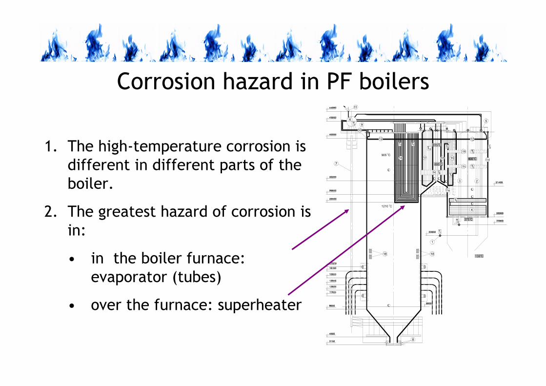
Corrosion hazard in PF boilers
1. The high-temperature corrosion is
different in different parts of the
boiler.
2. The greatest hazard of corrosion is
in:
• in the boiler furnace:
evaporator (tubes)
• over the furnace: superheater

COMBUSTION AND FUELS
Corrosion hazard due to application of
low-NOx combustion systems
1. In the major part of the low-NOx boiler furnace there is
reduction atmosphere, also near the furnace walls (tubes),
which enhances corrosion of tubes.
2. Due to the reduction atmosphere in the boundary layer of the
furnace walls the corrosion rate considerably increases:
• from 10 nm/h in normal boiler operation,
• to 600 nm/h in reduction atmosphere.

Efects of low-NOx corrosion
8 nm/h� 600 nm/h

Membrane walls damage due to
low-NOx corrosion
LPPP
D A
Tubethickness
4
3
2
6
5
1
4
3
2
6
5
1500 1500 2500 3500 4500 5500 6500 7500 8500 9500 10500 11500 12500 13500 14500
19000
20000
21000
22000
23000
24000
25000
26000
27000
28000
29000
30000
31000
32000
33000
[mm]
3.4
3.6
3.8
4.0
4.2
4.4
4.6
4.8
5.0P.OL. P.OL.
P.OL.
P.OL. P.OL.
P.OL.
OFA OFA
346
343
338
333
32
832
331
83
13
308
303
298
293
288
283
278
273
268
263
258
253
248
243
238
233
228
223
218
213
208
203
198
193
188
183
178
168
158
148
138
128
118
108
9888786858483828188
346
343
338
333
328
323
318
313
308
303
298
293
288
283
278
273
268
263
258
253
248
243
238
233
228
223
218
213
208
203
198
193
188
183
178
168
158
148
138
128
118
108
98
88
78
68
58
48
38
28
18
8
34
63
43
33
83
33
32
83
23
31
83
13
30
83
03
29
82
93
28
82
83
27
82
73
26
82
63
25
82
53
24
82
43
23
82
33
22
82
23
21
82
13
20
82
03
19
81
93
18
81
83
17
8
16
8
15
8
14
8
13
8
12
8
11
8
10
8
98
88
78
68
58
48
38
28
18
8
346
343
338
333
328
323
318
313
308
303
298
293
288
283
278
273
268
263
258
253
248
243
238
233
228
223
218
213
208
203
198
193
188
183
178
168
158
148
138
128
118
108
9888786858483828188
346
343
338
333
328
323
318
313
308
303
298
293
288
283
278
273
268
263
258
253
248
243
238
233
228
223
218
213
208
203
198
193
188
183
178
168
158
148
138
128
118
108
9888786858483828188
346
343
338
333
328
323
318
313
308
303
298
293
288
283
278
273
268
263
258
253
248
243
238
233
228
223
218
213
208
203
198
193
188
183
178
168
158
148
138
128
118
108
98
88
78
68
58
48
38
28
18
8
346
343
338
333
328
323
318
313
308
303
298
293
288
283
278
273
268
263
258
253
248
243
238
233
228
223
218
213
208
203
198
193
188
183
178
168
158
148
138
128
118
108
98
88
78
68
58
48
38
28
18
8
34
63
43
33
83
33
32
83
23
31
83
13
30
83
03
29
82
93
28
82
83
27
82
73
26
82
63
25
82
53
24
82
43
23
82
33
22
82
23
21
82
13
20
82
03
19
81
93
18
81
83
17
8
168
15
8
14
8
13
8
12
8
11
8
10
8
98
88
78
68
58
48
38
28
18
8
346
343
338
333
328
323
318
313
308
303
298
293
288
283
278
273
268
263
258
253
248
243
238
233
228
223
218
213
208
203
198
193
188
183
178
168
158
148
138
128
118
108
9888786858483828188
346
343
338
333
328
323
318
313
308
303
298
293
288
283
278
273
268
263
258
253
248
243
238
233
228
223
21
82
13
20
82
03
19
81
93
18
81
83
178
16
8
15
8
14
8
13
8
12
8
118
108
9888786858483828188
346
343
338
333
328
323
318
313
308
303
298
293
288
283
278
273
268
263
258
253
248
243
238
233
228
223
218
213
208
203
198
193
188
183
178
168
158
148
138
128
118
108
9888786858
48
3828
18
833 800
18 450

COMBUSTION AND FUELS
Sulphur corrosion
Sulphur corrosion is connected with the presence of alkali
metals in coal: potassium K and sodium Na, which
combined with sulphur form alkali sulfides Na2SO4 and
K2SO4 condensing on the tubes’ surface.
They aren’t directly responsible for corrosion because of
their melting high-temperature (Na2 SO4 − 884 i K2SO4 −1069 °C), however in the presence of SO3 they form
corrosive pirosulfides and trisulfides near the surface of
the evaporator tubes.

COMBUSTION AND FUELS
Reactions of sulphur corrosion
I. Pirosulfides
Na2SO4 + SO3 → Na2S2O7 (Tmelt = 389 °C)
K2SO4 + SO3 → K2S2O7 (Tmelt = 404 °C)
II. Trisulfides: sodium- and potassium-iron:
3Na2SO4 + Fe2O3 + 3SO3 → 2Na3Fe(SO4)3 (Ttopn= 624 °C)
3K2SO4 + Fe2O3 + 3SO3 → 2K3Fe(SO4)3 (Ttopn= 618 °C)

COMBUSTION AND FUELS
Hazard of sulphur corrosion due to application
of ultra-supercritical steam parameters

COMBUSTION AND FUELS
Corrosion hazard due to co-firing biomass
and coal – chlorine corrosion
Chlorine (Cl2) is particularly corrosive for steel at high
temperature. It causes active oxidation of metal removing
the protective layer of iron oxides, which are converted into
porous, not protecting deposit.
Sources of molecular chlorine (Cl2) near a tube surface are
present in flue gas hydrogen chloride (HCl) and present in
deposit alkali metals chlorides (KCl and NaCl).

COMBUSTION AND FUELS
Mechanism of chlorine corrosion
Chlorine diffuses through deposit to metal and reacts with it
Fe + Cl2 → FeCl2(s)
Metal chlorides formed on the metal surface have high pressure at the
temperature of 500 °C, therefore they diffuse through the protecting magnetite layer (Fe3O4) and damage it. After this iron chloride meets
oxygen and undergoes oxidation:
2FeCl2(g) + 3/2O2 → Fe2O3(s) + 2Cl2
3FeCl2(g) + 2O2 → Fe3O4(s) + 3Cl2
As a result a new layer of iron oxides is formed, however porous and not
protecting. Moreover released chlorine can return to metal.

COMBUSTION AND FUELS
Mechanism of chlorine corrosion
Metal Szlaka Faza gazowa
Cl2Fe
FeCl2 Fe O2 3
O2
Cr O2 3CrCl2Cr
Cl2
Metal Deposit Gas phase

COMBUSTION AND FUELS
Anti-corrosion protecting measures in
pulverized coal-fired boilers
1. Maintenance of oxidizing atmosphere in the boundary layer at
the furnace walls.
2. Reduction of temperature of steam approximately to 537 °C.
3. Application of protecting coatings.
4. Additives to flue gas neutralizing some corrosive agents.
5. Reduction of sulphur, chlorine and alkali metals in fuels.
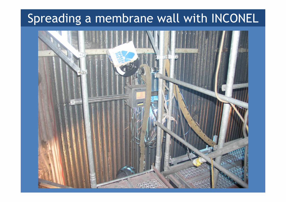
Spreading a membrane wall with INCONEL

Anti-corrosion protecting coating: INCONEL

Anti-corrosion protecting coating:
ceramic-metallic coating


