
Part Design and Optimization
By: Elliot Bushman
Modest Introduction
02/03/2021
(Not Good at ANSYS)🤫

External Integration
Car What other subsystems is this one reliant upon or are reliant upon it, what external factors or subteams should I consider?
System How does this part and subsystem play into subteam goals, how can this be done better?
Subsystem What role does this system play, how does it have to package, etc.?
Part Consider interfaces and purpose in subsystem
Ex: Car -> Controls System -> Steering System -> Steering Column

Approaching Model for a New Part1. Purpose and Integration
a. bolts, cables, bearings, other parts
2. Staticsa. Relative positioning and motion of multiple interfaceb. What forces and will each interface see and how will they be accounted for
3. Dynamicsa. What path will it take, potential for interference?b. Will motion change magnitude and orientation of forces?c. How many cycles will occur over life?
4. Manufacturinga. Machining, casting, printing, layup?

Internal Integration
1 Select Hardware
Fits within package of assembly
Sufficiently load ratings
Easy assembly and maintenance
2 Model
Accommodate critical hardware specs
Interfaces will all necessary components
Achieves function
Manufacturable
3 Assembly
Check all interfaces and connections
Interference and clearance assessment
Dynamics 4 Simulation
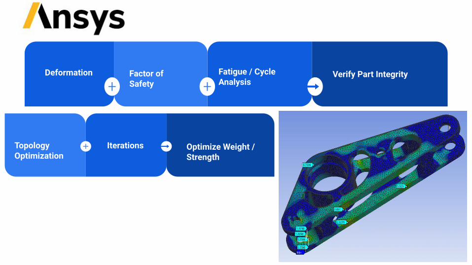
IterationsTopology Optimization
Optimize Weight / Strength
Fatigue / Cycle Analysis
Verify Part IntegrityFactor of Safety
Deformation

The Workbench
1. Type of analysis2. Simulation environment
parametersa. material properties
3. Model Being analyzeda. Import from Solidworks
4. Preparing model for simulationa. Mesh and connections
5. How exists in spacea. supports, forces,
6. Result of simulation7. Interpreting the solution
Link multiple analysis or results for second analysis
Up to D
ate
Wan
ts Upd
ate
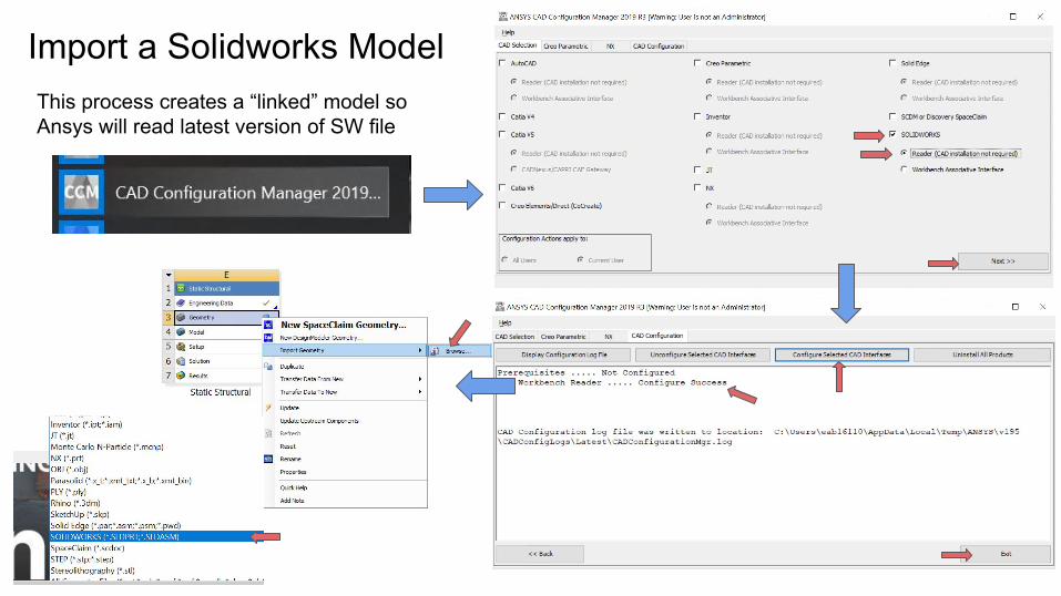
Import a Solidworks ModelThis process creates a “linked” model so Ansys will read latest version of SW file

● Simplified hardware make forces applications easier and more representative
● Apply material for each body○ hardware should always be steel
or titanium unless suspect it may fail or deflect
●

Frictionless connections are not the most representative but they are simpler to model
Consider how the bolt transfers force to the part and if the bolt itself applies and forces?

“Most important part”
● Different bodies will require different mesh qualities
● Inflation is your friend● Sometimes less is more
○ troubleshooting○ rapid changes
● Check the convergence of the mesh to ensure representative results

Constrains to 1 DOF!
Troubleshooting Friend
● Consider how the part is fixed in the car○ Bearing, pin, bolt, mount?○ How does this restrict freedom of part?
● Another place where including multiple bodies useful to give better representation of real work
○ ex: bond a body representing the bearing and fix it
(In this case my spring is my last constraint hindering tangential motion)

● Consider all of the possible ways forces will be applied to the part
○ Including non intended● Custom ording can make converting forces
to vectors for Ansys much easier● Will the part have multiple loading cases?● Can all of the loads be represented by
simple point forces?

What's the objective(s)
What's is being optimized
Process direction
Tune result
Setup derived from static

This result should act as guiding force for removing bulk from part
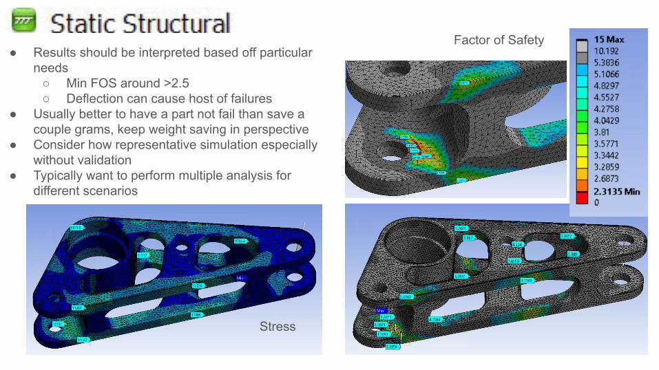
Factor of Safety
Stress
● Results should be interpreted based off particular needs
○ Min FOS around >2.5○ Deflection can cause host of failures
● Usually better to have a part not fail than save a couple grams, keep weight saving in perspective
● Consider how representative simulation especially without validation
● Typically want to perform multiple analysis for different scenarios

● How many cycles does this part see?○ Talk to DAQ!
● Again FOS >2.5● Does one particular area withstand
significantly less cycles?● Formula car drives relatively short time
This tells me that the bolt is going to wear on its mounting surfaces

Result
Your done, psyc. go back to start
● Does it still fit into subsystem?● Hardware requirements same?● Is it manufacturable?
Document your process!

Open Discussion & QuestionsThank you!


