Analysis of Reheating Furnaces in Steel Plant
Chirag Arya
Research Scholar Under Graduate
Department of Mechanical Engineering, JMIT Radaur
Pardeep Sharma
Research Scholar Under Graduate
Department of Mechanical Engineering, JMIT Radaur
Er. Kamlesh Kumar
Asst. Professor
Department of Mechanical Engineering, JMIT Radaur
Abstract:
The aim of this paper is to analyze the Recuperative Burner and Regenerative Burner for various
types of reheating furnaces in steel plant. A survey is done on various furnace used in steel plant
and such Equipment has been designed and installed in order to achieve optimization in
reheating process. The flue gases temperatures of the burners are determined to suit with the
sizes of the reheating furnaces by considering the air temperature, the fuel cost and the
investment cost. As per considerations, the Regenerative Burner is more suitable in steels plants
and better life span.
Keywords : Energy Balance, Recuperative Burner, Regenerative Burner, Reheating Furnace.
International Journal of Scientific & Engineering Research, Volume 6, Issue 5, May-2015 ISSN 2229-5518
20
IJSER © 2015 http://www.ijser.org
IJSER
1) Introduction:
Today's burning question for the human race
that how to transfer the dependency on the
fossil fuel into renewable environment
friendly sources. At the present time, the
fuel cost has increased highly which affected
the production cost of the steel. the average
energy costs of steel industry are about 15%
- 30% of the production cost. Now the main
focus of manufacturing industry is on
increasing energy efficiency of their
production processes. The fuel is used in the
reheating furnace to heat the billet or the
slab in the rolling process. In Thailand, the
waste heat is recovered to preheat the
combustion air by using the recuperator, the
air preheater, the waste heat boiler, the
economizer, and the high efficiency burner.
The steel industry is currently using the
recuperator, which can preheat the
temperature of the combustion air upto 300°
C and the efficiency is nearly 30%. The high
efficiency burner is the new approach to
save the energy used in the reheating
furnaces, which have the exhaust gas at high
temperature during the burning process of
steel. The high efficiency burner is proposed
instead of the recuperator and the
conventional burner. It can preheat the
temperature of the combustion air about
600° C to 800°C and the efficiency can
increase up to 90% with the energy saving
of 10% to 20%.
2) Introduction to Regenerative
Burner and Recuperative Burner:
The structure of the recuperative burner is
same as that of radiation heat exchanger
tube which heats the inlet air up to the
higher temperature about 750° C by
recovering the heat from the exhaust gas to
the inlet air. Hence, the exchanged heat in
the burner can improve the combustion
efficiency and save the fuel cost
approximately 25% to 30%.
A regenerative burner is a combustion
heating system allowing extremely high-
efficient recovery of exhaust heat in the
industrial furnace by transferring the heat
from exhaust gas to inlet air that will be
used in the combustion. Owing to its great
reduction effect of fuel efficiency, this
system has been specifically adopted and
popularized in relatively high temperature
furnaces, including heating furnaces for
rolling, forging furnaces, heat treatment
furnaces, melting furnaces, baking furnaces,
and deodorizing furnaces, as a superb means
for saving cost energy and reducing CO2.(
http://www.osakagas.co.jp)
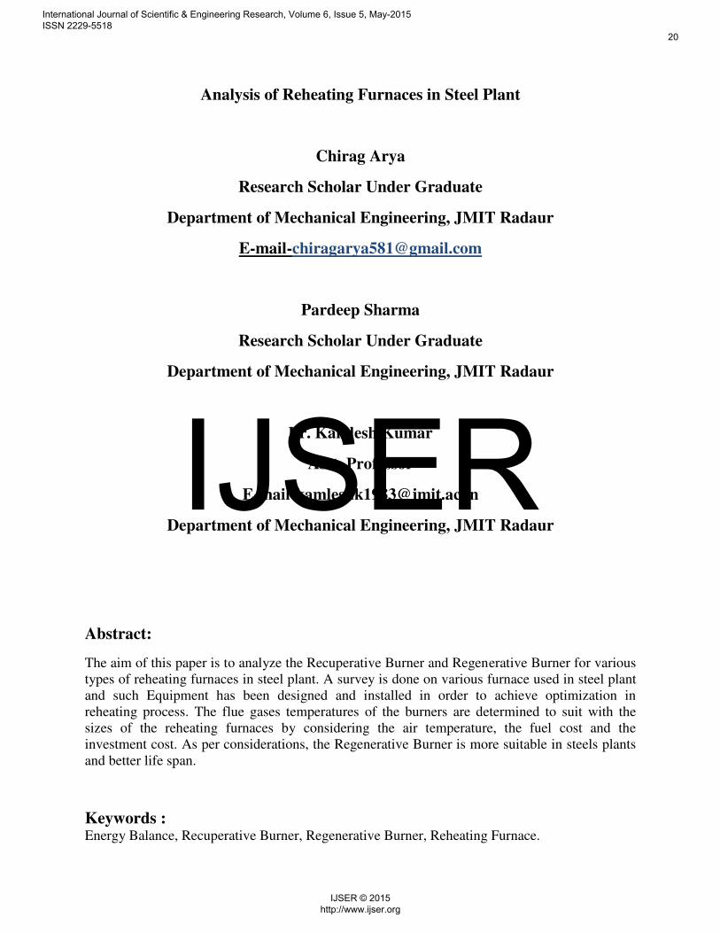
Figure 1:Number of accumulated sales units
of Osaka gas regenerative burner
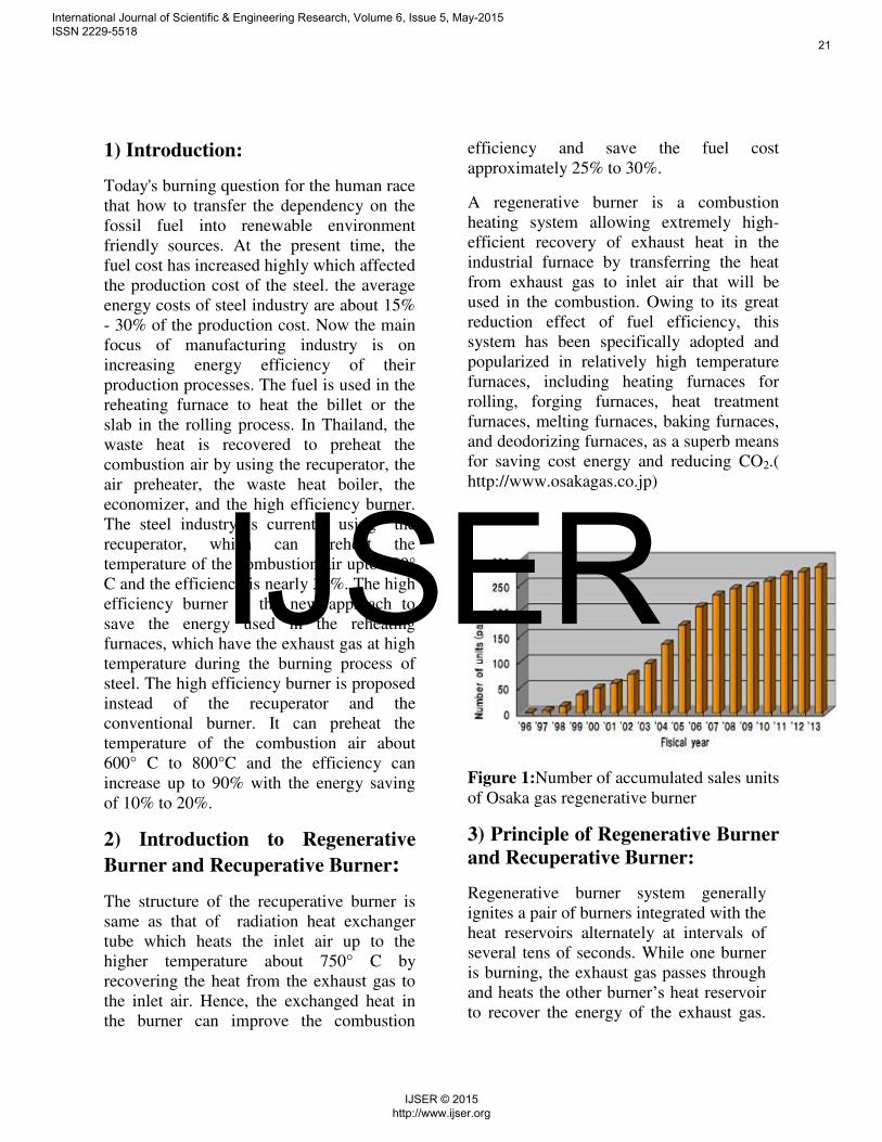
3) Principle of Regenerative Burner
and Recuperative Burner:
Regenerative burner system generally
ignites a pair of burners integrated with the
heat reservoirs alternately at intervals of
several tens of seconds. While one burner
is burning, the exhaust gas passes through
and heats the other burner’s heat reservoir to recover the energy of the exhaust gas.
International Journal of Scientific & Engineering Research, Volume 6, Issue 5, May-2015 ISSN 2229-5518
21
IJSER © 2015 http://www.ijser.org
IJSER
Then, when the other burner burns, the air
for combustion in turn passes through the
preheated heat reservoir to recover the
exhaust gas energy which had
conventionally been wasted, to provide
high efficient combustion.
Figure 2: Principle of Regenerative Burner
system
Figure 3: Principle of Recuperative Burner
System
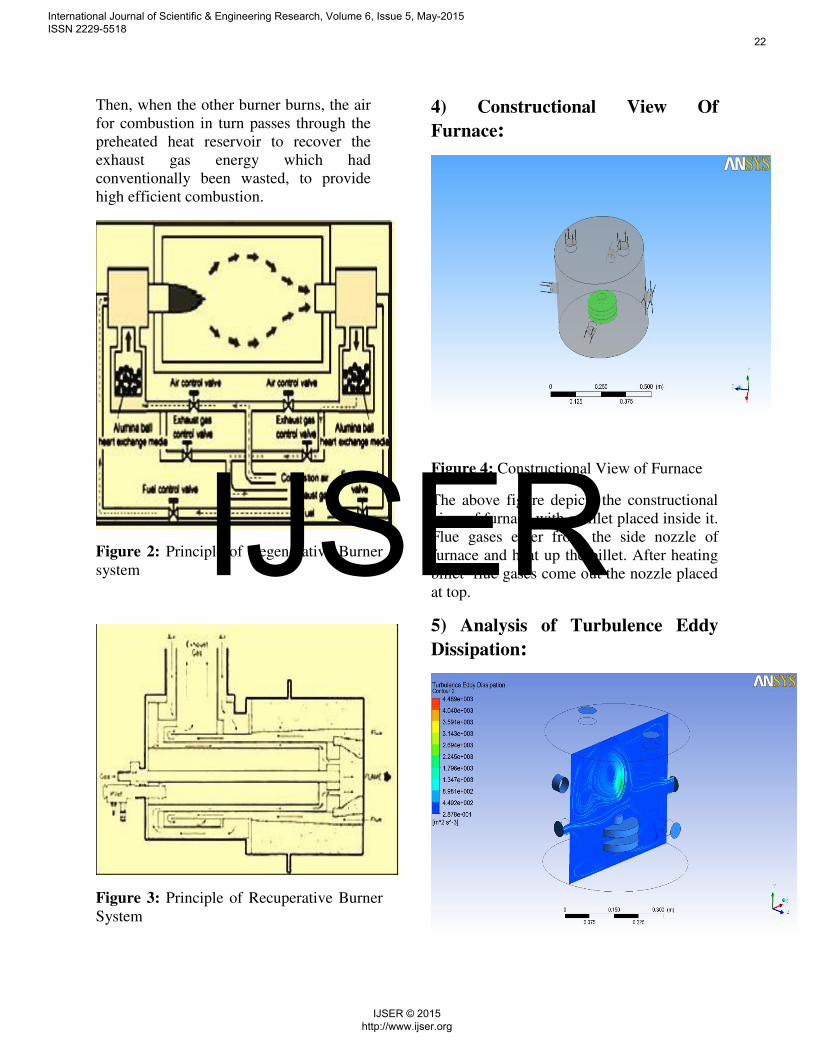
4) Constructional View Of
Furnace:
Figure 4: Constructional View of Furnace
The above figure depicts the constructional
view of furnace with a billet placed inside it.
Flue gases enter from the side nozzle of
furnace and heat up the billet. After heating
billet flue gases come out the nozzle placed
at top.
5) Analysis of Turbulence Eddy
Dissipation:
International Journal of Scientific & Engineering Research, Volume 6, Issue 5, May-2015 ISSN 2229-5518
22
IJSER © 2015 http://www.ijser.org
IJSER
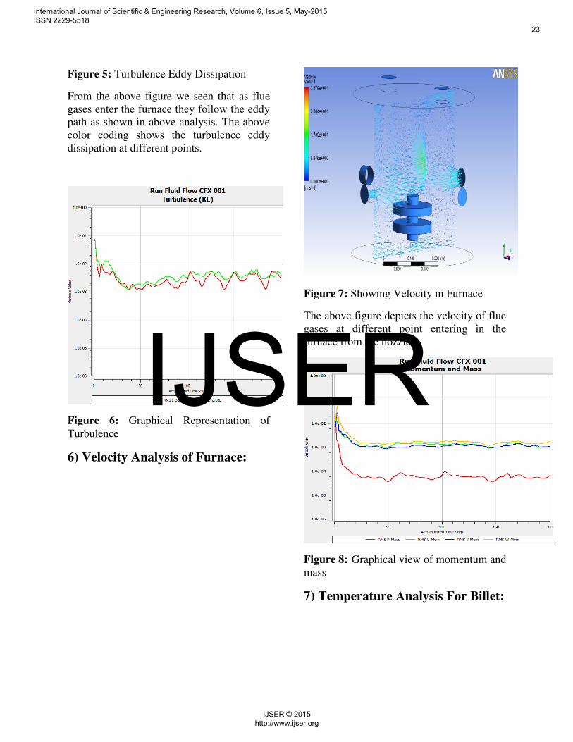
Figure 5: Turbulence Eddy Dissipation
From the above figure we seen that as flue
gases enter the furnace they follow the eddy
path as shown in above analysis. The above
color coding shows the turbulence eddy
dissipation at different points.
Figure 6: Graphical Representation of
Turbulence
6) Velocity Analysis of Furnace:
Figure 7: Showing Velocity in Furnace
The above figure depicts the velocity of flue
gases at different point entering in the
furnace from the nozzle.
Figure 8: Graphical view of momentum and
mass
7) Temperature Analysis For Billet:
International Journal of Scientific & Engineering Research, Volume 6, Issue 5, May-2015 ISSN 2229-5518
23
IJSER © 2015 http://www.ijser.org
IJSER

Figure 9:Temperature Analysis for Billet
This figure indicates the different
temperature value at various point of billet.
from the above analysis we concluded that
upper portion of billet has low temperature
than the lower portion of the billet.
8) Temperature Analysis in
Furnace:
International Journal of Scientific & Engineering Research, Volume 6, Issue 5, May-2015 ISSN 2229-5518
24
IJSER © 2015 http://www.ijser.org
IJSER
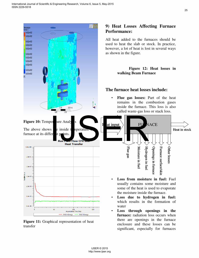
Figure 10: Temperature Analysis
The above shows the inside temperature of
furnace at its different points.
Figure 11: Graphical representation of heat
transfer
9) Heat Losses Affecting Furnace
Performance:
All heat added to the furnaces should be
used to heat the slab or stock. In practice,
however, a lot of heat is lost in several ways
as shown in the figure.
Figure 12: Heat losses in
walking Beam Furnace
The furnace heat losses include:
• Flue gas losses: Part of the heat
remains in the combustion gases
inside the furnace. This loss is also
called waste-gas loss or stack loss.
• Loss from moisture in fuel: Fuel
usually contains some moisture and
some of the heat is used to evaporate
the moisture inside the furnace.
• Loss due to hydrogen in fuel: which results in the formation of
water
• Loss through openings in the
furnace: radiation loss occurs when
there are openings in the furnace
enclosure and these losses can be
significant, especially for furnaces
FURNACE
Flu
e gas
Mo
isture in
fuel
Op
enin
gs in
furn
ace
Furn
ace su
rface/skin
Oth
er losse
s
Heat input
Heat in stock
Hyd
rogen in
fuel
FURNACE
Flu
e gas
Mo
isture in
fuel
Op
enin
gs in
furn
ace
Furn
ace su
rface/skin
Oth
er losse
s
Heat input
Heat in stock
Hyd
rogen in
fuel
International Journal of Scientific & Engineering Research, Volume 6, Issue 5, May-2015 ISSN 2229-5518
25
IJSER © 2015 http://www.ijser.org
IJSER

operating at temperatures above
600°C. A second loss is through air
infiltration because the draft of
furnace chimneys cause a negative
pressure inside the furnace, drawing
in air through leaks or cracks or
whenever the furnace doors are
opened.
• Furnace skin / surface losses, also
called wall losses: while
temperatures inside the furnace are
high, heat is conducted through the
roof, floor and walls and emitted to
the ambient air once it reaches the
furnace skin or surface.
• Other losses: there are several other
ways in which heat is lost from a
furnace, although quantifying these
is often difficult, for example, losses
due to formation of scales.
10) Efficiency of Furnace:
A furnace’s efficiency increases when the percentage of heat that is transferred to the
stock inside the furnace increases. The
efficiency of the furnace can be calculated in
two ways:
Direct method
Indirect Method
Direct method:
• The efficiency of a furnace can be
determined by measuring the amount
heat absorbed by the stock and
dividing this by the total amount of
fuel consumed.
• Thermal efficiency of the furnace
=Heat in the stock / Heat in the fuel
consumed for heating the stock
• The quantity of heat (Q) that will be
transferred to stock can be calculated
with this equation:
Q = m x Cp (t1 – t2)
Where,
Q = Quantity of heat of stock in kCal
m = Weight of the stock in kg
Cp= Mean specific heat of stock in kCal/kg
oC
t1 = Final temperature of stock in oC
t2 = Initial temperature of the stock before
it enters the furnace in °C
The heat input is 400 liters per hour. The
specific gravity of fuel is used to convert
this into kg. Therefore: 400 l/hr x 0.92 kg/l =
368 kg/hr
The heat output is calculated as follows:
= m x Cp x ΔT
= 6000 kg x 0.12 x (1340 – 40)
= 936000 k Cal
The efficiency is:
= (heat input / heat output) x 100
= [(936000 / (368 x 10000)] x 100 = 25.43
percent
The approximate heat loss is 100% – 25% =
75%
• The furnace efficiency can also be
determined through the indirect method,
similar to the evaluation of boiler
efficiency. The principle is simple: the
heat losses are subtracted from the heat
supplied to the furnace. (Note that a
detailed methodology to calculate each
International Journal of Scientific & Engineering Research, Volume 6, Issue 5, May-2015 ISSN 2229-5518
26
IJSER © 2015 http://www.ijser.org
IJSER

individual heat loss is provided in the
chapter) • Adding the losses a to f up gives the
total losses:
• Flue gas loss
= 57.29 %
• Loss due to moisture in
fuel = 1.36
%
• Loss due to H2 in fuel
= 9.13 %
• Loss due to openings in
furnace = 5.56
%
• Loss through furnace skin
= 2.64 %
• Total losses
= 75.98 %
The furnace efficiency calculated through
the indirect method = 100 – 75.98 = 24.02%
11) Conclusion:
The suitable preheating air temperatures of
two burners for 3 plants are investigated for
the reheating furnaces in Thailand. It is
found that the regenerative burner can save
the energy more than the recuperative burner
at the preheating air temperature at 900°C,
which is suitable for all reheating furnace
capacities based on the considerations of the
net present value for the project time of 60
years and the shorter payback periods. The
sensitivity analysis is also discussed for all
factors which are not affected the NPV of
the project. It is understood that the
investment of the high efficiency burner is
required to save the energy used in the
reheating furnace. Hence, it is an alternative
way to install the regenerative burner in the
reheating furnace for the steel industry to
save the energy cost.
References:
1)http://www.osakagas.co.jp/en/rd/technical/
1198856_6995.html
2)https://www.google.co.in/search?q=princi
ple+of+regenerative+furnace&espv=2&biw
=1366&bih=628&source=lnms&tbm=isch&
sa=X&ei=EYg3VZfJHo69uAT6voDwDg&
ved=0CAYQ_AUoAQ#imgrc=_
3) C.E. Baukal, Jr.,Industrial burner
handbook, 2004.
4) http://ccgi.hotworkct.plus.com/cms/
index.php?page=more-5.
5) Information on dealers regenerative
burner.
6) Information on dealers recuperative
burner.
7) Information on
http://www.eppo.go.th/retail_prices.html
International Journal of Scientific & Engineering Research, Volume 6, Issue 5, May-2015 ISSN 2229-5518
27
IJSER © 2015 http://www.ijser.org
IJSER


