
CA-COM Industrial Connectors

www.ittcannon.com4
Our connector portfolio remains the most extensive in the industry, offering a reliable and cost
effective range of interconnect solutions with the brands of Cannon, VEAM and BIW Connector
Systems. Continuous investment in technology and research & development have enabled ITT to
provide new, innovative products and solutions to markets including:
ITT Inc.
ITT is a diversified leading manufacturer of highly engineered critical
components and customized technology solutions for the energy,
transportation and industrial markets. Building on its heritage of
innovation, ITT partners with its customers to deliver enduring solutions
to the key industries that underpin our modern way of life. Founded in
1920, ITT is headquartered in White Plains, N. Y., with employees in more
than 35 countries and sales in a total of approximately 125 countries.
For more information, visit www.itt.com.

www.ittcannon.com 5
Our connector portfolio remains the most extensive in the industry, offering a reliable and cost effective range of interconnect solutions
Automotive
Oil & Gas
Commercial & Military Aerospace
Computer, Telecom & Consumer Electronics
Transportation
lndustrial / lnstrumentation
Defense Vehicles

www.ittcannon.com
Dimensions shown in mm | Specifications and dimensions subject to change
6
Introduction to CA-COM
ITT Cannon’s circular connector’s series CA-COM and CA-COM-B are
derivations of the connectors know as SAE-AS50151
(formerly MIL-DTL-5015) and VG95234. Initially designed for military
aircraft and combat vehicle application the CA-COM versions have
been modified especially for the utilization in various industrial areas.
Connectors of both CA-COM series are intermateable and interchangeable
with the corresponding types as per SAE-AS50151 and VG95234 as they
offer the same mounting dimensions and contact arrangements. The
entire CA-COM connector line is ROHS compliant.
Features and benefits
• The CA-COM standard version is featured by a threaded coupling system while the CA-COM-B types are coined by a “Reverse bayonet” coupling mechanism that offers exceptional vibration protection by a simple 120° turn. The CA-COM-B coupling unit is featured by roller bolts made of stainless steel rolling down the mating ramp, thus reducing coupling torque.
• Various backshell and adapter options, like PG metric gland and heatshrink boot are available amongst others.
• Insulators are made of high quality polychloroprene, which are good for temperatures up to 125°. This material is self-extinguishing, resistant against various fluids like gasoline, lubricants and other fluids of such nature (short time wetting only). In case of lifetime moistening FKM insulator material can be offered as an alternative.
• The contacts are made of copper alloy plated with hard silver finish good for at least 500 mating cycles. There are solder, crimp and PCB contacts in place. The crimp contacts offer a comprehensive range of termination reductions (see pages 41 and 42).
• All solder contacts are ROHS compliant due to a special passivation.
Contact us for detail or your request for a customized solution.
Vital Information:2D and 3 D drawings, connector specifications are available on ITT Cannon#s web page: www.ittcannon.com Please insert the full connector part number into the keyword search field.

www.ittcannon.com
Dimensions shown in mm | Specifications and dimensions subject to change
7
How to use this catalogue .................................... 6
Product overview ...................................................7
Part number creation ........................................ 8 – 9
Ordering reference ...............................................10
Contact arrangements .................................... 11–15
Mounting dimensions ..........................................16
Seperating and coupling dimensions ....................17
Wall mounting receptacles with endbells ....... 18 – 21
Cable connecting plugs ................................. 22 – 25
Wall mounting receptacles ............................ 26 – 29
Straight Plugs ................................................ 30 – 33
Right Angle Plugs ......................................... 34 – 36
Accessories – Protective caps ......................... 37 – 38
Accessories ................................................... 39 – 40
Contacts ....................................................... 41 – 42
Tooling.......................................................... 43 – 44
Product safety information ...................................45
Table of contents

www.ittcannon.com
Dimensions shown in mm | Specifications and dimensions subject to change
8
Select your product using either the “part number creation” or the “ordering reference” option
Use the detail pages to better understand the available options like connector styles, contact arrangements and contacts options
Add accessories and tooling options on the related pages. A connector assembly instruction is available upon request or visit www.ittcannon.com: Enter Keyword "CA Bayonet Assembly Instruction"
Use the contact information on the back cover to contact us for further questions or to get advise on where you can purchase our products
1
2
3
4
How to use
This catalog is split in several sections that help you to
• Get an impression what this product is all about (Introduction)
• Get a general overview of all product lines (product overview)
• Get all required detail information (contact arrangements, product details)
• Get all required supporting products (accessories and tooling)
The fastest way to find your product of choice is to follow these steps

www.ittcannon.com
Dimensions shown in mm | Specifications and dimensions subject to change
9
Product overviewELECTRICAL DATA
Contact Rating at 20°C (68°F), ambient temperature
Contact size (AWG/metric) Rated Current (A max.) ¹
16S /15S 22
16 /15 22
12 41
8/60/100 74
4 /160 135
0 /500 245
¹ This applies only to the max. rated current for one contact. If several contacts in one contact arrangement are loaded with higher current the temperature may not exceed 125°C
Rated Current vs. Ambient Temperature
Contacts Resistance (Millivolt test)
Contact size Contact resistance
(AWG/metric) mΩ max.
16S /15S 6,0
16 /15 6,0
12/25 3,0
8 /100 1,0
4 /160 0,3
0 /500 0,2
Insulation Resistance ≥ 1000 MΩ
Air and Creepage Path (min.)
Voltage class Instr. A D
Air path, mm 0,7 1,1 2,8
Creepage path, mm 0,7 1,1 2,8
Operation VoltageAs according to specification these connectors are suitable for an operating voltage of 50 Vrms (see Product safety information). However, this is only valid when the connectors are freely accessible during operation and consequently might be touchable.
Test voltage
Service rating Test voltage Vrms
Instruments 1050
A 2000
B 4500
D 2500
E 3500
MECHANICAL FEATURES
Ambient temperature
–55/125°C (– 67/257°F)
ENVIRONMENTAL SEALING Acc. to DIN EN 60068-1
Threaded: Up to IP 65 (in mated condition)
Bayonet: Up to IP 67 (in mated condition)
Mating Cycles min. 500
Min. Separating Force per Contact
Contact size Separating force
metric AWG N min
15S /15 16S /16 1,0
25 12 1,5
60/100 8 3,0
160 4 4,0
500 0 8,5
Contact Retention Apply test force in mating direction
Contact size Test force
metric AWG N
15S /15 16S /16 35
25 12 55
60/100 8 80
160 4 90
500 0 95
Coupling TorqueThe admissible coupling torque has to be tested under harnessed condition
Admissible torque
Closing and opening (Nmmax) Opening (Nmmin)
Shell size CA-COM CA-COM-B
10SL 3,0 1,7 0,15
12S 2,8 2,5 0,23
14S 5,9 3,6 0,35
16S/16 7,0 5,5 0,46
18 8,0 8,0 0,58
20 9,0 9,0 0,70
22 10,6 11,0 0,80
24 12,9 14,0 0,80
28 16,7 17,0 0,92
32 18,1 19,0 1,02
36 23,9 23,0 1,05
Materials
Shell Aluminum alloy, Zinc die cast, nickel plated
Contacts Copper alloy, silver plated
Insulator /Grommet Polychloroprene

www.ittcannon.com
Dimensions shown in mm | Specifications and dimensions subject to change
10
Part number creation plugFollow these steps to design your connector part number.
Design your part number as per above steps
CA-COM-BExample
STEP 1 STEP 2 STEP 3 STEP 4 STEP 5 STEP 6Shell style Class / Backshell Contact arrangement Contact gender Insulation rotation Mod code (max. 4 codes)
CA06COM E 20 – 27 S W B – 02
CA-COMExample
STEP 1 STEP 2 STEP 3 STEP 4 STEP 5 STEP 6Shell style Class / Backshell Contact arrangement Contact gender Insulation rotation Mod code (max. 4 codes)
CA06COM E 20 – 27 S W – 01 – DN
STEP 1 Select shell style (plug)
Shell Style Straight Plug Plug 90°
Bayonet
CA06COM-B
Threaded
CA06COM
Bayonet
CA08COM-B
Threaded
CA08COM
STEP 2 Choose backshell
Class FFor Flex tube
Class PG; MEFor PG or Metric cable glands
Class E General duty, strain relief
Class E Environmental, grommet seal, heat shrink boot adapter Mod. -03; -06 (bayonet), Mod. DN (threaded)
Class E, 90°General duty, strain relief
Class F, 90° For Flex tube
STEP 3 Choose layout see page 11 –14 for layouts
STEP 4 Choose gender P=pin S=socket
STEP 5 Choose rotation see page 15 for rotation (omit for normal position)
STEP 6 Choose modification see page 10 for modifications
www.ittcannon.com
Dimensions shown in mm | Specifications and dimensions subject to change
11
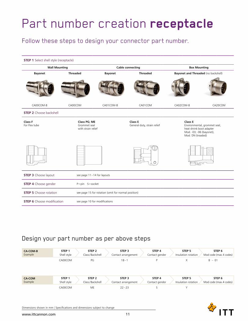
Part number creation receptacle
Design your part number as per above steps
Follow these steps to design your connector part number.
CA-COM-BExample
STEP 1 STEP 2 STEP 3 STEP 4 STEP 5 STEP 6Shell style Class / Backshell Contact arrangement Contact gender Insulation rotation Mod code (max. 4 codes)
CA00COM PG 18 – 1 P X B – 01
CA-COMExample
STEP 1 STEP 2 STEP 3 STEP 4 STEP 5 STEP 6Shell style Class / Backshell Contact arrangement Contact gender Insulation rotation Mod code (max. 4 codes)
CA00COM ME 22 – 23 S Y
STEP 1 Select shell style (receptacle)
Wall Mounting Cable connecting Box Mounting
Bayonet
CA00COM-B
Threaded
CA00COM
Bayonet
CA01COM-B
Threaded
CA01COM
Bayonet and Threaded (no backshell)
CA02COM-B CA20COM
STEP 2 Choose backshell
Class FFor Flex tube
Class PG; ME Grommet seal with strain relief
Class EGeneral duty, strain relief
Class EEnvironmental, grommet seal, heat shrink boot adapter Mod. -03; -06 (bayonet), Mod. DN (treaded)
STEP 3 Choose layout see page 11 –14 for layouts
STEP 4 Choose gender P=pin S=socket
STEP 5 Choose rotation see page 15 for rotation (omit for normal position)
STEP 6 Choose modification see page 10 for modifications

www.ittcannon.com
Dimensions shown in mm | Specifications and dimensions subject to change
12
Ordering reference
Series CA – Cannon Designation
Shell type
00 – Wall mounting receptacle see page 18 –21
01 – cable connecting plug see page 22 –25
02 – Box mounting receptacle see page 26+28
20 – Box mounting receptacle, rear mounting see page 27+29
06 – Plug, straight see page 30 –33
08 – Plug, 90° see page 34 –36
Class
COM-E – Endbell with cable clamp¹
COM-F – Endbell for flex tube
COM-PG – Adapter for PG-termination
COM-ME – Adapter for Metric-termination
COM-L – PCB solder termination
Shell size
10SL, 12S, 14S, 16, 16S, 18, 20, 22, 24, 28, 32, 36
Contact arrangement see page 11 –15
Contact type
P – pin
S – socket
Alternate insert position see page 14
Insulator rotation
Coupling
B – Bayonet coupling (without designation = threaded coupling)
Modification
01 – Metric crimp contacts
03 – Adapter for heat shrink boots and metric crimp contacts (bayonet coupling only)
06 – Adapter for heat shrink boots and solder pot contacts (bayonet coupling only)
44 – With endring and grommet (individual wire sealing, Class E and F only)
48 – F endbell with O-Ring
BM29 – Threaded flange holes, shell styles 02, 20 and 00 (threaded coupling only)
DN – Adapter for heat shrink boots (threaded coupling only)
F0 – Without contacts (to be ordered separately)
¹ except shell style 02 / 20
Part number explanation CACA
COM-ECOM-E
PP
WW
B– XXXX
0606
18-118-1

www.ittcannon.com
Dimensions shown in mm | Specifications and dimensions subject to change
13
CONTACT ARRANGEMENTS
Figure No. of contacts Contact arrangements Service rating Insulator positionContact size W X Y Z
3 10SL-3 15S A – – – –
2 10SL-4 15S A – – – –
4 12SA-10 15S A – – – –
3 14S-1 15S A – – – –
4 14S-2 15S Inst. – 120 240 –
5 14S-5 15S Inst. – 110 – –
6 14S-6 15S Inst. – – – –
3 14S-7 15S A 90 180 270 –
7 14SA7 15S Inst. – – – –
7 16S-1 15S A 80 – – 280
5 16S-8 15S A – 170 265 –
32 1
16-7 15 (A, B) 8 (C)
A 80 110 250 280
42 2
16-9 15 (B, D) 25 (A, C)
A 35 110 250 325
3 16-10 25 A 90 180 270 –
1 16-12 4 A 0 – – –
10 18-1 15 A (B,C,F,G)
Inst. (all other)70 145 – 290
4 18-4 15 D 35 110 250 325
www.ittcannon.com
Dimensions shown in mm | Specifications and dimensions subject to change
14
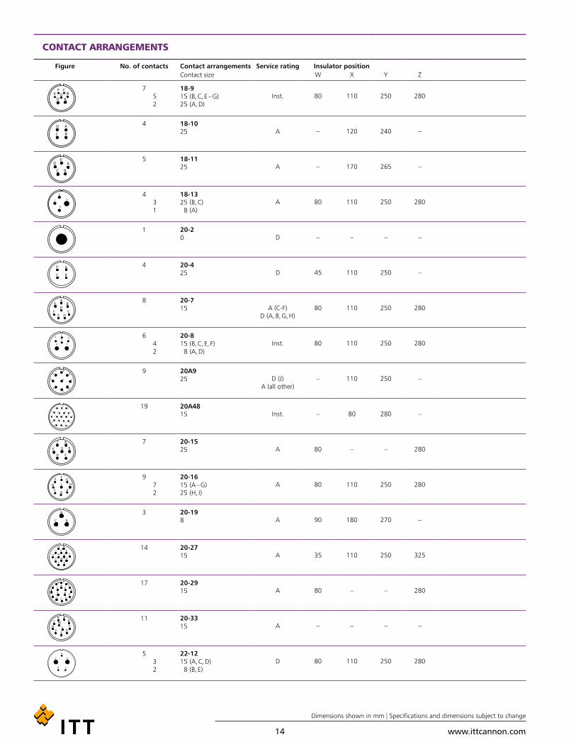
CONTACT ARRANGEMENTS
Figure No. of contacts Contact arrangements Service rating Insulator positionContact size W X Y Z
752
18-915 (B, C, E – G)25 (A, D)
Inst. 80 110 250 280
4 18-1025 A – 120 240 –
5 18-1125 A – 170 265 –
43 1
18-1325 (B, C) 8 (A)
A 80 110 250 280
1 20-20 D – – – –
4 20-425 D 45 110 250 –
8 20-715 A (C-F)
D (A, B, G, H) 80 110 250 280
64 2
20-815 (B, C, E, F) 8 (A, D)
Inst. 80 110 250 280
9 20A925 D (J)
A (all other)– 110 250 –
19 20A48 15 Inst. – 80 280 –
7 20-1525 A 80 – – 280
972
20-1615 (A – G)25 (H, I)
A 80 110 250 280
3 20-198 A 90 180 270 –
14 20-2715 A 35 110 250 325
17 20-2915 A 80 – – 280
11 20-3315 A – – – –
53 2
22-1215 (A, C, D) 8 (B, E)
D 80 110 250 280

www.ittcannon.com
Dimensions shown in mm | Specifications and dimensions subject to change
15
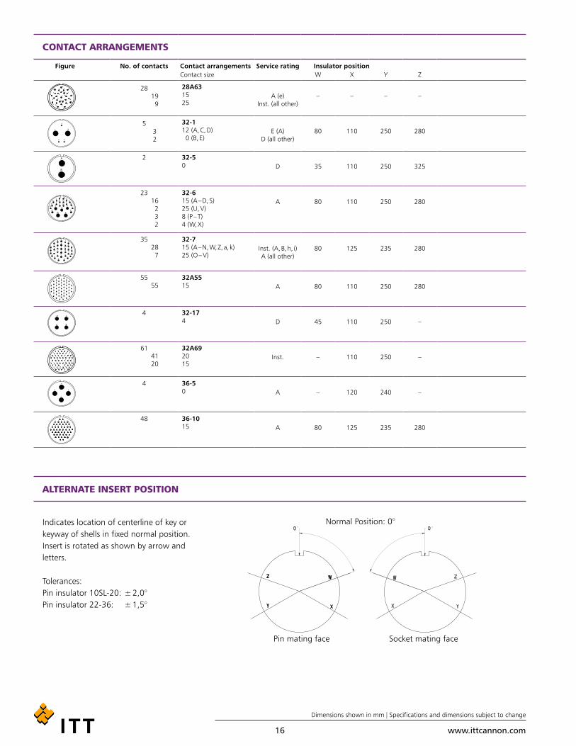
CONTACT ARRANGEMENTS
Figure No. of contacts Contact arrangements Service rating Insulator position Special insulator positionContact size W X Y Z
19 22-14 15 A 80 – – 280
14 22-19 15 A 80 110 250 280
4 22-22 8 A – 110 250 –
8 22-23 25 D (H)
A (all other)35 – 250 –
7 24-2 25 D 80 – – 280
1614 2
24-7 15 (A-M,O) 25 (P,N)
Inst. 80 110 250 280
7 24-10 8 A 80 – – 280
96 3
24-11 25 (A – C, G – I) 8 (D. F)
A 35 110 250 325
119 2
24-20 15 (A – D, G L) 25 (E, F)
A 80 110 250 280
4 24-22 8 D 45 110 250 –
24 24-28 15 Inst. 80 110 250 280
2218 4
28-11 15 (A – I, N – X) 25 (J – M)
A 80 110 250 280
26 28-12 15 A 90 180 270 –
35 28-15 15 A 80 110 250 280
144
10
28-20 15 (K – N) 25 (A – J, P)
A 80 110 250 280
37 28-21 15 A 80 110 250 280
95 4
28A16 16 4
Inst. – – – – 2 4 912
260110250280
www.ittcannon.com
Dimensions shown in mm | Specifications and dimensions subject to change
16
CONTACT ARRANGEMENTS
Figure No. of contacts Contact arrangements Service rating Insulator positionContact size W X Y Z
2819 9
28A63 15 25
A (e) Inst. (all other)
– – – –
53 2
32-1 12 (A, C, D) 0 (B, E)
E (A) D (all other)
80 110 250 280
2 32-5 0 D 35 110 250 325
2316 2 3 2
32-6 15 (A – D, S) 25 (U, V) 8 (P – T) 4 (W, X)
A 80 110 250 280
3528 7
32-7 15 (A – N, W, Z, a, k) 25 (O – V)
Inst. (A, B, h, i)A (all other)
80 125 235 280
5555
32A55 15 A 80 110 250 280
4 32-17 4 D 45 110 250 –
6141 20
32A69 20 15
Inst. – 110 250 –
4 36-5 0 A – 120 240 –
48 36-10 15 A 80 125 235 280
ALTERNATE INSERT POSITION
Indicates location of centerline of key or keyway of shells in fixed normal position. Insert is rotated as shown by arrow and letters.
Tolerances:Pin insulator 10SL-20: ± 2,0°Pin insulator 22-36: ± 1,5°
Normal Position: 0°
Socket mating facePin mating face

www.ittcannon.com
Dimensions shown in mm | Specifications and dimensions subject to change
17
CONTACT ARRANGEMENTS
Contact count per contact arrangement
On pages 11–14 the contact arrangements are shown by shell sizes. The table below gives an overview on the number of contacts, contact size and per contact arrangement.
Contact Arrangement
No. of Contacts Contact Size
Contact Arrangement
No. of Contacts Contact Size
10 15S 15 25 8 4 0 10 15S 15 25 8 4 0
16-12 1 1 20A9 9 9
20-2 1 1 20-16 9 7 2
24-11 9 6 3
10SL-4 2 2 28A16 9 5 4
32-5 2 2
18-1 10 10
10SL-3 3 3
14S-1 3 3 20-33 11 11
14S-7 3 3 24-20 11 9 2
16-7 3 2 1
16-10 3 3 20-27 14 14
20-19 3 3 22-19 14 14
28-20 14 4 10
12SA10 4 4
14S-2 4 4 24-7 16 14 2
16-9 4 2 2
18-4 4 4 20-29 17 17
18-10 4 4
18-13 4 3 1 20A48 19 19
20-4 4 4 22-14 19 19
22-22 4 4
24-22 4 4 28-11 22 18 4
32-17 4 4
36-5 4 4 32-6 23 16 2 3 2
14S-5 5 5 24-28 24 24
16S-8 5 5
18-11 5 5 28-12 26 26
22-12 5 3 2
32-1 5 3 2 28A63 28 19 9
14S-6 6 6 28-15 35 35
20-8 6 4 2 32-7 35 28 7
14SA7 7 7 28-21 37 37
16S-1 7 7
18-9 7 5 2 36-10 48 48
20-15 7 7
24-2 7 7 32A55 55 55
24-10 7 7
32A69 61 41 20
20-7 8 8
22-23 8 8

www.ittcannon.com
Dimensions shown in mm | Specifications and dimensions subject to change
18
MOUNTING HOLES
HARNESSING
WIRING HINTS
WIRE STRIPPING
Shell size CA-COM Threaded CA-COM-Bayonet Mounting holes for connectors styles, complete receptacle range
d1 H12 d1 H12 d2 H13 e d1 H12 d1 H12 d2 H13
CA00… , CA20... CA02… CA00… , CA20... CA02…
10SL 16,0 16,4 3,4 18,2 19,1 17,0 3,4
12S 19,1 16,4 3,4 20,6 22,0 17,0 3,4
14S 22,3 19,7 3,4 23,0 25,5 20,0 3,4
16S /16 25,5 22,9 3,4 24,6 28,3 23,0 3,4
18 28,7 26,1 3,4 27,0 31,7 26,5 3,4
20 31,8 29,5 3,4 29,4 35,0 30,0 3,4
22 35,0 32,7 3,4 31,8 38,3 33,0 3,4
24 38,2 36,0 3,9 34,9 41,8 36,0 3,9
28 44,5 42,0 3,9 39,7 47,6 42,0 3,9
32 50,9 48,3 4,5 44,5 54,3 48,5 4,5
36 57,2 53,1 4,5 49,2 60,5 55,0 4,5
CA-COM connectors are designed for single wire harnessing, if an individual wire sealing grommet is used. Wires have to conform to wire and insulation diameters with the data given in the following table:
Either mechanical or hot stripping can be used. Prevent conduc-tors or insulators damage. For solder contacts, conductors have to be pretinned.Note: Do not twist conductors used with crimp contacts. Do not touch uninsulated conductors before crimping, twisting of conductors and grease or lubricants on the wires cause poor crimp quality.
Contact size Crimp / solder contacts Insulation Ø
AWG metric AWG metric AWG metric
mm mm² mm
– 10 – 0,75-1,0 – 1,45-2,5
16S /15S 16/15 16 0,75-1,5 1,6-2,8 1,60-2,8
12 25 12 2,5 2,9-3,5 2,9-3,5
– 60 – 6,0 – 3,5-4,9
8 100 8 10,0 4,2-5,8 5,5-6,5
4 160 4 16,0 6,2-9,0 7,1-9,0
0 500 0 50,0 10,5-13,0 10,5-13,0
Contact size Stripping length
AWG metric mm
– 10 4,0 + 0,4
16S/15S 16/15 6,0 + 0,5
12 25 6,0 + 0,5
8 60/100 11,0 + 0,8 – 0,4
4 160 11,0 + 0,8 – 0,4
0 500 13,0 + 0,8 – 0,4
Strip wires carefully. Do not damage conductors and insulation. For solder connections, wires have to be pretinned. Do not twist conductors used in crimp contacts, otherwise no perfect crimp connection will be achieved. Do not touch conductors before crimping. Film of grease or lubricants on the strands will cause poor crimp quality.
For detailled assembly instructions please visit www.ittcannon.com and search for the keyword "CA Bayonet Assembly Instruction".

www.ittcannon.com
Dimensions shown in mm | Specifications and dimensions subject to change
19
SEPARATING AND COUPLING DIMENSIONS
Shell sizel1
minl2
minl3
minl4
minl5
minl6
minl7
maxl8
max
10SL 70 70 65 80 70 65 3,5 8,0
12S 70 75 65 80 75 70 3,5 8,0
14S 70 75 65 80 75 80 3,5 8,0
16S 70 90 65 80 80 80 3,5 8,0
16 80 100 70 100 90 100 3,5 8,0
18 90 100 70 110 95 110 3,5 8,0
20 90 100 70 110 95 110 3,5 8,0
22 90 100 70 110 95 110 3,5 8,0
24 110 120 90 120 105 120 5,0 8,0
28 110 120 90 120 105 120 5,0 9,0
32 110 180 90 120 115 120 6,0 9,0
36 110 190 100 130 120 130 6,0 9,0
PLUGCA06COM-ECA06COM-E-B
CA06COM-E-DNCA06COM-E-B-03/-06
RECEPTACLECA02COM-ECA02COM-E-B
PLUGCA06COM-FCA06COM-F-B
CA06COM-PGCA06COM-PG-B
RECEPTACLECA02COM-ECA02COM-E-B
PLUGCA08COM-ECA08COM-E-B
CA06COM-E-DNCA006COM-E-B
RECEPTACLECA02COM-ECA20COM-E
CA02COM-E-BCA20COM-E-B

www.ittcannon.com
Dimensions shown in mm | Specifications and dimensions subject to change
20
WALL MOUNTING RECEPTACLE CLASS PG OR ME
CA00COM-PG-B with bayonet coupling, CA00COM-ME-B CA00COM-PG / ME-B is a wall mounting receptacle for usage of PG or Metric glands. It mates with plugs CA06COM-B and CA08COM-B
Part No. (pin insert*) d1 d2 d3 l1 l2 l3 I4 e– 0,15 PG-Thread Metric Thread max + 0,4 + 0,2 ± 0,3 ± 0,1
CA00COM-PG10SL-*P-B-*** CA00COM-ME10SL-**P-B-*** 18,2 PG9 M16 × 1,5 M4 56 18,20 2,8 25,4 18,2
CA00COM-PG12S-**P-B-*** CA00COM-ME12S-**P-B-*** 21,4 PG9 M16 × 1,5 M4 56 18,20 3,2 28,0 20,6
CA00COM-PG14S-**P-B-*** CA00COM-ME14S-**P-B-*** 24,6 PG11 M20 × 1,5 M4 56 18,20 3,2 30,0 23,0
CA00COM-PG16S-*P-B-*** CA00COM-ME16S-**P-B-*** 27,4 PG13,5 M20 × 1,5 M4 58 18,20 3,2 32,5 24,6
CA00COM-PG16-**P-B-*** CA00COM-ME16-**P-B-*** 27,4 PG13,5 M20 × 1,5 M4 66 23,05 3,2 32,5 24,6
CA00COM-PG18-**P-B-*** CA00COM-ME18-**P-B-*** 30,8 PG13,5 M25 × 1,5 M4 73 23,05 4,0 35,0 27,0
CA00COM-PG20-**P-B-*** CA00COM-ME20-**P-B-*** 34,2 PG16 M25 × 1,5 M4 74, 23,05 4,0 38,0 29,4
CA00COM-PG22-**P-B-*** CA00COM-ME22-**P-B-*** 37,4 PG16 M32 × 1,5 M4 77 23,05 4,0 41,0 31,8
CA00COM-PG24-**P-B-*** CA00COM-ME24-**P-B-*** 40,9 PG16 M32 × 1,5 M4 77 23,05 4,0 44,5 34,9
CA00COM-PG28-**P-B-*** CA00COM-ME28-**P-B-*** 46,7 PG21 M32 × 1,5 M5 78 24,05 4,0 50,8 39,7
CA00COM-PG32-**P-B-*** CA00COM-ME32-**P-B-*** 53,4 PG29 M40 × 1,5 M5 78 24,05 4,0 57,0 44,5CA00COM-PG36-**P-B-*** CA00COM-ME36-**P-B-*** 59,6 PG29 M40 × 1,5 M5 89 24,05 4,0 63,5 49,2
CA00COM-PG with threaded coupling, CA00COM-ME CA00COM-PG / ME is a wall mounting receptacle for usage of PG or metric glands. It mates with plugs CA06COM and CA08COM
Part No. (pin insert*) A d1 d2 l1 l2 l3 I4 eThread + 0,2 / – 0,1 PG-Thread Metric max + 0,4 ± 0,3 ± 0,3 ± 0,1
CA00COM-PG10SL-*P-*** CA00COM-ME10SL-**P-*** 5/8-24UNEF-2A 3,1 PG9 M16 × 1,5 52 14,2 2,8 25,4 18,2
CA00COM-PG12S-**P-*** CA00COM-ME12S-**P-*** 3/4-20UNEF-2A 3,1 PG9 M16 × 1,5 52 14,2 3,2 28,0 20,6
CA00COM-PG14S-**P-*** CA00COM-ME14S-**P-*** 7/8-20UNEF-2A 3,1 PG11 M20 × 1,5 52 14,2 3,2 30,0 23,0
CA00COM-PG16S-*P-*** CA00COM-ME16S-**P-*** 1-20UNEF-2A 3,1 PG13,5 M20 × 1,5 54 14,2 3,2 32,5 24,6
CA00COM-PG16-**P-*** CA00COM-ME16-**P-*** 1-20UNEF-2A 3,1 PG13,5 M20 × 1,5 64 19,0 3,2 32,5 24,6
CA00COM-PG18-**P-*** CA00COM-ME18-**P-*** 1-1/8-18UNEF-2A 3,1 PG13,5 M25 × 1,5 69 19,0 4,0 35,0 27,0
CA00COM-PG20-**P-*** CA00COM-ME20-**P-*** 1-1/4-18UNEF-2A 3,1 PG16 M25 × 1,5 70 19,0 4,0 38,0 29,4
CA00COM-PG22-**P-*** CA00COM-ME22-**P-*** 1-3/8-18UNEF-2A 3,1 PG16 M32 × 1,5 73 19,0 4,0 41,0 31,8
CA00COM-PG24-**P-*** CA00COM-ME24-**P-*** 1-1/2-18UNEF-2A 3,7 PG16 M32 × 1,5 74 20,6 4,0 44,5 34,9
CA00COM-PG28-**P-*** CA00COM-ME28-**P-*** 1-3/4-18UNEF-2A 3,7 PG21 M32 × 1,5 74 20,6 4,0 50,8 39,7
CA00COM-PG32-**P-*** CA00COM-ME32-**P-*** 2-18UNS-2A 4,4 PG29 M40 × 1,5 76 22,2 4,0 57,0 44,5
CA00COM-PG36-**P-*** CA00COM-ME36-**P-*** 2-1/4-16UN-2A 4,4 PG29 M40 × 1,5 87 22,2 4,0 63,5 49,2
* For socket inserts substitute "S" for "P" **Add contact arrangement number; see pages 11–15 *** Add modification code; see page 10 (bottom)
www.ittcannon.com
Dimensions shown in mm | Specifications and dimensions subject to change
21
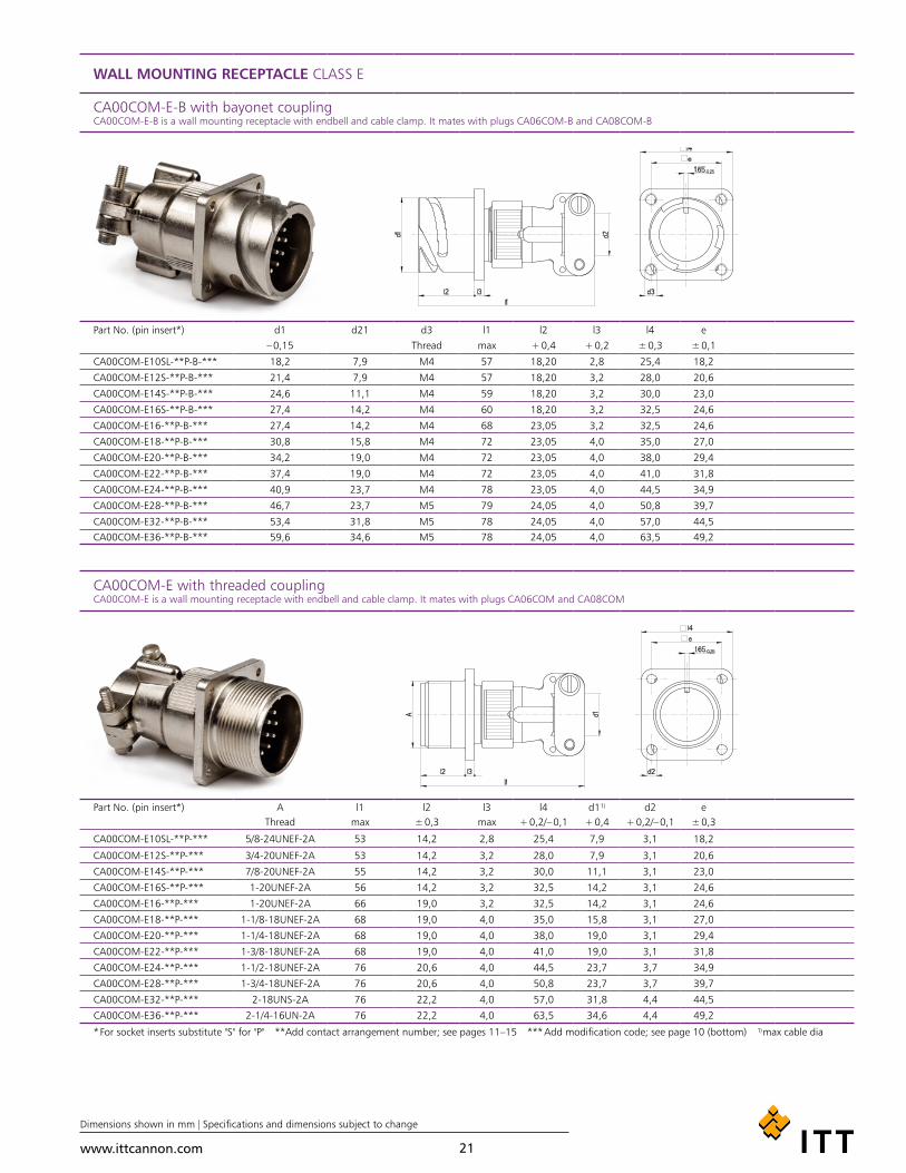
WALL MOUNTING RECEPTACLE CLASS E
CA00COM-E-B with bayonet coupling CA00COM-E-B is a wall mounting receptacle with endbell and cable clamp. It mates with plugs CA06COM-B and CA08COM-B
Part No. (pin insert*) d1 d21 d3 l1 l2 l3 l4 e– 0,15 Thread max + 0,4 + 0,2 ± 0,3 ± 0,1
CA00COM-E10SL-**P-B-*** 18,2 7,9 M4 57 18,20 2,8 25,4 18,2
CA00COM-E12S-**P-B-*** 21,4 7,9 M4 57 18,20 3,2 28,0 20,6
CA00COM-E14S-**P-B-*** 24,6 11,1 M4 59 18,20 3,2 30,0 23,0
CA00COM-E16S-**P-B-*** 27,4 14,2 M4 60 18,20 3,2 32,5 24,6
CA00COM-E16-**P-B-*** 27,4 14,2 M4 68 23,05 3,2 32,5 24,6
CA00COM-E18-**P-B-*** 30,8 15,8 M4 72 23,05 4,0 35,0 27,0
CA00COM-E20-**P-B-*** 34,2 19,0 M4 72 23,05 4,0 38,0 29,4
CA00COM-E22-**P-B-*** 37,4 19,0 M4 72 23,05 4,0 41,0 31,8
CA00COM-E24-**P-B-*** 40,9 23,7 M4 78 23,05 4,0 44,5 34,9
CA00COM-E28-**P-B-*** 46,7 23,7 M5 79 24,05 4,0 50,8 39,7
CA00COM-E32-**P-B-*** 53,4 31,8 M5 78 24,05 4,0 57,0 44,5CA00COM-E36-**P-B-*** 59,6 34,6 M5 78 24,05 4,0 63,5 49,2
CA00COM-E with threaded coupling CA00COM-E is a wall mounting receptacle with endbell and cable clamp. It mates with plugs CA06COM and CA08COM
Part No. (pin insert*) A l1 l2 l3 l4 d1¹) d2 eThread max ± 0,3 max + 0,2/– 0,1 + 0,4 + 0,2/– 0,1 ± 0,3
CA00COM-E10SL-**P-*** 5/8-24UNEF-2A 53 14,2 2,8 25,4 7,9 3,1 18,2
CA00COM-E12S-**P-*** 3/4-20UNEF-2A 53 14,2 3,2 28,0 7,9 3,1 20,6
CA00COM-E14S-**P-*** 7/8-20UNEF-2A 55 14,2 3,2 30,0 11,1 3,1 23,0
CA00COM-E16S-**P-*** 1-20UNEF-2A 56 14,2 3,2 32,5 14,2 3,1 24,6
CA00COM-E16-**P-*** 1-20UNEF-2A 66 19,0 3,2 32,5 14,2 3,1 24,6
CA00COM-E18-**P-*** 1-1/8-18UNEF-2A 68 19,0 4,0 35,0 15,8 3,1 27,0
CA00COM-E20-**P-*** 1-1/4-18UNEF-2A 68 19,0 4,0 38,0 19,0 3,1 29,4
CA00COM-E22-**P-*** 1-3/8-18UNEF-2A 68 19,0 4,0 41,0 19,0 3,1 31,8
CA00COM-E24-**P-*** 1-1/2-18UNEF-2A 76 20,6 4,0 44,5 23,7 3,7 34,9
CA00COM-E28-**P-*** 1-3/4-18UNEF-2A 76 20,6 4,0 50,8 23,7 3,7 39,7
CA00COM-E32-**P-*** 2-18UNS-2A 76 22,2 4,0 57,0 31,8 4,4 44,5
CA00COM-E36-**P-*** 2-1/4-16UN-2A 76 22,2 4,0 63,5 34,6 4,4 49,2
* For socket inserts substitute "S" for "P" **Add contact arrangement number; see pages 11–15 *** Add modification code; see page 10 (bottom) ¹) max cable dia

www.ittcannon.com
Dimensions shown in mm | Specifications and dimensions subject to change
22
WALL MOUNTING RECEPTACLE CLASS F
CA00COM-F-B with bayonet coupling CA00COM-F-B is a wall mounting receptacle with endbell for flextubes. It mates with plugs CA06COM-B and CA08COM-B
Part No. (pin insert*) d1 d2 d3¹) d4 l1 l2 l3 I4 l5 e– 0,15 Thread Thread max + 0,4 ± 0,2 ± 0,3 min ± 0,1
CA00COM-F10SL-**P-B-*** 18,2 M4 8,2 5/8-24UNEF-2A 52 18,20 2,8 25,4 9,5 18,2
CA00COM-F12S-**P-B-*** 21,4 M4 8,2 5/8-20UNEF-2A 52 18,20 3,2 28,0 9,5 20,6
CA00COM-F14S-**P-B-*** 24,6 M4 11,1 3/4-20UNEF-2A 52 18,20 3,2 30,0 9,5 23,0
CA00COM-F16S-**P-B-*** 27,4 M4 14,3 7/8-20UNEF-2A 59 18,20 3,2 32,5 9,5 24,6
CA00COM-F16-**P-B-*** 27,4 M4 14,3 7/8-20UNEF-2A 59 23,05 3,2 32,5 9,5 24,6
CA00COM-F18-**P-B-*** 30,8 M4 16,7 1-20UNEF-2A 63 23,05 4,0 35,0 9,5 27,0
CA00COM-F20-**P-B-*** 34,2 M4 19,8 1-3/16-18UNEF-2A 63 23,05 4,0 38,0 9,5 29,4
CA00COM-F22-**P-B-*** 37,4 M4 19,8 1-3/16-18UNEF-2A 66 23,05 4,0 41,0 9,5 31,8
CA00COM-F24-**P-B-*** 40,9 M4 25,4 1-7/16-18UNEF-2A 69 23,05 4,0 44,5 9,5 34,9
CA00COM-F28-**P-B-*** 46,7 M5 27,0 1-7/16-18UNEF-2A 70 24,05 4,0 50,8 9,5 39,7
CA00COM-F32-**P-B-*** 53,4 M5 32,5 1-3/4-18UNS-2A 71 24,05 4,0 57,0 11,0 44,5CA00COM-F36-**P-B-*** 59,6 M5 35,7 2-18UNS-2A 73 24,05 4,0 63,5 11,8 49,2
CA00COM-F with threaded coupling CA00COM-F is a wall mounting receptacle with endbell for flex tubes. It mates with plugs CA06COM and CA08COM
Part No. (pin insert*) A d2 d3¹) d4 l1 l2 l3 I4 l5 eThread + 0,2/– 0,1 Thread max + 0,4 ± 0,3 ± 0,3 min ± 0,1
CA00COM-F10SL-**P-*** 5/8-24UNEF-2A 3,1 8,2 5/8-24UNEF-2A 45 14,2 2,8 25,4 9,5 18,2
CA00COM-F12S-**P-*** 3/4-20UNEF-2A 3,1 8,2 5/8-20UNEF-2A 45 14,2 3,2 28,0 9,5 20,6
CA00COM-F14S-**P-*** 7/8-20UNEF-2A 3,1 11,1 3/4-20UNEF-2A 45 14,2 3,2 30,0 9,5 23,0
CA00COM-F16S-**P-*** 7/8-20UNEF-2A 3,1 14,3 7/8-20UNEF-2A 45 14,2 3,2 32,5 9,5 24,6
CA00COM-F16-**P-*** 1-20UNEF-2A 3,1 14,3 7/8-20UNEF-2A 54 19,0 3,2 32,5 9,5 24,6
CA00COM-F18-**P-*** 1-1/8-18UNEF-2A 3,1 16,7 1-20UNEF-2A 54 19,0 4,0 35,0 9,5 27,0
CA00COM-F20-**P-*** 1-1/4-18UNEF-2A 3,1 19,8 1-3/16-18UNEF-2A 55 19,0 4,0 38,0 9,5 29,4
CA00COM-F22-**P-*** 1-3/8-18UNEF-2A 3,1 19,8 1-3/16-18UNEF-2A 58 19,0 4,0 41,0 9,5 31,8
CA00COM-F24-**P-*** 1-1/2-18UNEF-2A 3,7 25,4 1-7/16-18UNEF-2A 59 20,6 4,0 44,5 9,5 34,9
CA00COM-F28-**P-*** 1-3/4-18UNEF-2A 3,7 27,0 1-7/16-18UNEF-2A 60 20,6 4,0 50,8 9,5 39,7
CA00COM-F32-**P-*** 2-18UNS-2A 4,4 32,5 1-3/4-18UNS-2A 62 22,2 4,0 57,0 11,0 44,5
CA00COM-F36-**P-*** 2-1/4-16UN-2A 4,4 35,7 2-18UNS-2A 64 22,2 4,0 63,5 11,8 49,2
* For socket inserts substitute "S" for "P" **Add contact arrangement number; see pages 11–15 *** Add modification code; see page 10 (bottom) ¹) max cable dia

www.ittcannon.com
Dimensions shown in mm | Specifications and dimensions subject to change
23
WALL MOUNTING RECEPTACLE CLASS E
CA00COM-E-B/-03/-06 with bayonet coupling CA00COM-E-B/-03/-06 is a wall mounting receptacle (wire sealing) for heat shrink boots. It mates with plugs CA06COM-B and CA08COM-B
Part No. (pin insert*) d1 d2 d3 d4¹) d5 l1 l2 l3 l4 l5 e– 0,15 Thread ± 0,2 max max + 0,4 ± 0,3 ± 0,3 ± 0,5 ± 0,1
CA00COM-E10SL-**P-B-*** 18,2 M4 15,5 7,7 13,3 53 18,20 2,8 25,4 11,7 18,2
CA00COM-E12S-**P-B-*** 21,4 M4 15,5 7,9 13,3 53 18,20 3,2 28,0 11,7 20,6
CA00COM-E14S-**P-B-*** 24,6 M4 19,1 10,6 17,0 53 18,20 3,2 30,0 11,7 23,0
CA00COM-E16S-**P-B-*** 27,4 M4 23,9 13,5 21,9 53 18,20 3,2 32,5 11,7 24,6
CA00COM-E16-**P-B-*** 27,4 M4 23,9 13,5 21,9 61 23,05 3,2 32,5 11,5 24,6
CA00COM-E18-**P-B-*** 30,8 M4 23,9 14,6 21,9 62 23,05 4,0 35,0 11,5 27,0
CA00COM-E20-**P-B-*** 34,2 M4 29,6 14,6 26,2 64 23,05 4,0 38,0 12,7 29,4
CA00COM-E22-**P-B-*** 37,4 M4 29,6 20,8 26,2 64 23,05 4,0 41,0 12,7 31,8
CA00COM-E24-**P-B-*** 40,9 M4 37,8 24,6 34,5 64 23,05 4,0 44,5 12,7 34,9
CA00COM-E28-**P-B-*** 46,7 M5 37,8 27,0 34,5 66 24,05 4,0 50,8 12,7 39,7
CA00COM-E32-**P-B-*** 53,4 M5 47,8 33,3 43,6 69 24,05 4,0 57,0 15,2 44,5CA00COM-E36-**P-B-*** 59,6 M5 47,8 38,5 43,6 70 24,05 4,0 63,5 15,2 49,2
CA00COM-E-DN with threaded coupling CA00COM-E-DN is a wall mounting receptacle with endbell (wire sealing) for heat shrink boots. It mates with plugs CA06COM and CA08COM
Part No. (pin insert*) A d2 d3 d4¹) d5 l1 l2 l3 I4 l5 eThread + 0,2/– 0,1 ± 0,2 max max + 0,4 ± 0,3 ± 0,5 ± 0,3 ± 0,1
CA00COM-E10SL-**P-DN 5/8-24UNEF-2A 3,1 15,5 7,7 13,3 49,0 14,2 2,8 11,7 25,4 18,2
CA00COM-E12S-**P-DN 3/4-20UNEF-2A 3,1 15,5 7,9 13,3 49,0 14,2 3,2 11,7 28,0 20,6
CA00COM-E14S-**P-DN 7/8-20UNEF-2A 3,1 19,1 10,6 17,0 49,0 14,2 3,2 11,7 30,0 23,0
CA00COM-E16S-**P-DN 1-20UNEF-2A 3,1 23,9 13,5 21,9 49,0 14,2 3,2 11,7 32,5 24,6
CA00COM-E16-**P-DN 1-20UNEF-2A 3,1 23,9 13,5 21,9 58,0 19,0 3,2 11,5 32,5 24,6
CA00COM-E18-**P-DN 1-1/8-18UNEF-2A 3,1 23,9 14,6 21,9 58,0 19,0 4,0 11,5 35,0 27,0
CA00COM-E20-**P-DN 1-1/4-18UNEF-2A 3,1 23,9 14,6 26,2 60,0 19,0 4,0 12,7 35,0 27,0
CA00COM-E22-**P-DN 1-3/8-18UNEF-2A 3,1 29,6 20,8 26,2 60,0 19,0 4,0 12,7 41,0 31,8
CA00COM-E24-**P-DN 1-1/2-18UNEF-2A 3,7 37,8 24,6 34,5 63,0 20,6 4,0 12,7 44,5 34,9
CA00COM-E28-**P-DN 1-3/4-18UNEF-2A 3,7 37,8 27,0 34,5 63,0 20,6 4,0 12,7 50,8 39,7
CA00COM-E32-**P-DN 2-18UNS-2A 4,4 47,8 33,3 43,6 67,0 22,2 4,0 15,2 57,0 44,5
CA00COM-E36-**P-DN 2-1/4-16UN-2A 4,4 47,8 38,5 43,6 68,0 22,2 4,0 15,2 63,5 49,2
* For socket inserts substitute "S" for "P" **Add contact arrangement number; see pages 11–15 *** -03: with metric crimp contacts / -06: with solder pot contacts ¹) max cable dia

www.ittcannon.com
Dimensions shown in mm | Specifications and dimensions subject to change
24
CABLE CONNECTING PLUG CLASS PG OR ME
CA01COM-PG-B with bayonet coupling, CA01COM-ME-B CA01COM-PG/ME-B is a cable connecting plug for usage of PG or metric glands. It mates with plugs CA06COM-B and CA08COM-B
Part No. PG (pin insert*) Part No. ME (pin insert*) d1 d2 d3 l1 l2 l3 l5– 0,15 PG-Thread Metric max max + 0,4 + 0,2 ± 0,2
CA01COM-PG10SL-**P-B-*** CA01COM-ME10SL-**P-B-*** 18,2 PG9 M16 × 1,5 25,2 56 18,2 2,8 20,6
CA01COM-PG12S-**P-B-*** CA01COM-ME12S-**P-B-*** 21,4 PG9 M16 × 1,5 27,8 56 18,20 3,2 23,8
CA01COM-PG14S-**P-B-*** CA01COM-ME14S-**P-B-*** 24,6 PG11 M20 × 1,5 29,8 56 18,20 3,2 25,4
CA01COM-PG16S-**P-B-*** CA01COM-ME16S-**P-B-*** 27,4 PG13,5 M20 × 1,5 32,3 58 18,20 3,2 28,6
CA01COM-PG16-**P-B-*** CA01COM-ME16-**P-B-*** 27,4 PG13,5 M20 × 1,5 32,3 66 23,05 3,2 28,6
CA01COM-PG18-**P-B-*** CA01COM-ME18-**P-B-*** 30,8 PG13,5 M25 × 1,5 34,8 73 23,05 4,0 31,7
CA01COM-PG20-**P-B-*** CA01COM-ME20-**P-B-*** 34,2 PG16 M25 × 1,5 37,8 74 23,05 4,0 34,9
CA01COM-PG22-**P-B-*** CA01COM-ME22-**P-B-*** 37,4 PG16 M32 × 1,5 41,1 77 23,05 4,0 38,1
CA01COM-PG24-**P-B-*** CA01COM-ME24-**P-B-*** 40,9 PG16 M32 × 1,5 44,6 77 23,05 4,0 41,3
CA01COM-PG28-**P-B-*** CA01COM-ME28-**P-B-*** 46,7 PG21 M32 × 1,5 50,9 78 24,05 4,0 47,6
CA01COM-PG32-**P-B-*** CA01COM-ME32-**P-B-*** 53,4 PG29 M40 × 1,5 57,1 78 24,05 4,0 54,0CA01COM-PG36-**P-B-*** CA01COM-ME36-**P-B-*** 59,6 PG29 M40 × 1,5 63,6 89 24,05 4,0 60,6
CA01COM-PG with threaded coupling CA01COM-PG/ME is a cable connecting plug for usage of PG or metric glands. It mates with plugs CA06COM and CA08COM
Part No. PG (pin insert*) Part No. ME (pin insert*) A d1 d2 l1 l2 l3 l4Thread max PG-Thread Metric max + 0,4 ± 0,3 max
CA01COM-PG10SL-**P-*** CA01COM-ME10SL-**P-*** 5/8-24UNEF-2A 16,2 PG9 M16 × 1,5 52 14,2 2,8 21,8
CA01COM-PG12S-**P-*** CA01COM-ME12S-**P-*** 3/4-20UNEF-2A 19,4 PG9 M16 × 1,5 52 14,2 3,2 25,0
CA01COM-PG14S-**P-*** CA01COM-ME14S-**P-*** 7/8-20UNEF-2A 22,5 PG11 M20 × 1,5 52 14,2 3,2 28,2
CA01COM-PG16S-**P-*** CA01COM-ME16S-**P-*** 1-20UNEF-2A 25,7 PG13,5 M20 × 1,5 54 14,2 3,2 31,4
CA01COM-PG16-**P-*** CA01COM-ME16-**P-*** 1-20UNEF-2A 25,7 PG13,5 M20 × 1,5 64 19,0 3,2 31,4
CA01COM-PG18-**P-*** CA01COM-ME18-**P-*** 1-1/8-18UNEF-2A 28,9 PG13,5 M25 × 1,5 69 19,0 4,0 34,5
CA01COM-PG20-**P-*** CA01COM-ME20-**P-*** 1-1/4-18UNEF-2A 32,1 PG16 M25 × 1,5 70 19,0 4,0 37,3
CA01COM-PG22-**P-*** CA01COM-ME22-**P-*** 1-3/8-18UNEF-2A 35,2 PG16 M32 × 1,5 73 19,0 4,0 40,9
CA01COM-PG24-**P-*** CA01COM-ME24-**P-*** 1-1/2-18UNEF-2A 38,4 PG16 M32 × 1,5 74 20,6 4,0 43,8
CA01COM-PG28-**P-*** CA01COM-ME28-**P-*** 1-3/4-18UNEF-2A 44,8 PG21 M32 × 1,5 74 20,6 4,0 50,4
CA01COM-PG32-**P-*** CA01COM-ME32-**P-*** 2-18UNS-2A 51,1 PG29 M40 × 1,5 76 22,2 4,0 56,8
CA01COM-PG36-**P-*** CA01COM-ME36-**P-*** 2-1/4-16UN-2A 57,5 PG29 M40 × 1,5 87 22,2 4,0 63,1
* For socket inserts substitute "S" for "P" **Add contact arrangement number; see pages 11–15 *** Add modification code; see page 10 (bottom)

www.ittcannon.com
Dimensions shown in mm | Specifications and dimensions subject to change
25
CABLE CONNECTING PLUG CLASS E
CA01COM-E-B with bayonet coupling CA01COM-E-B is a cable connecting plug with endbell and cable clamp. It mates with plugs CA06COM-B and CA08COM-B
Part No. (pin insert) d1 d2 ¹) d3 l1 l2 l3 I4– 0,15 max max + 0,4 ± 0,2 ± 0,2
CA01COM-E10SL-**P-B-*** 18,2 7,9 25,2 57 18,20 2,8 20,6
CA01COM-E12S-**P-B-*** 21,4 7,9 27,8 57 18,20 3,2 23,8
CA01COM-E14S-**P-B-*** 24,6 11,1 29,8 59 18,20 3,2 25,4
CA01COM-E16S-**P-B-*** 27,4 14,2 32,3 60 18,20 3,2 28,6
CA01COM-E16-**P-B-*** 27,4 14,2 32,3 68 23,05 3,2 28,6
CA01COM-E18-**P-B-*** 30,8 15,8 34,8 72 23,05 4,0 31,7
CA01COM-E20-**P-B-*** 34,2 19,0 37,8 72 23,05 4,0 34,9
CA01COM-E22-**P-B-*** 37,4 19,0 41,1 72 23,05 4,0 38,1
CA01COM-E24-**P-B-*** 40,9 23,7 44,6 78 23,05 4,0 41,3
CA01COM-E28-**P-B-*** 46,7 23,7 50,9 79 24,05 4,0 47,6
CA01COM-E32-**P-B-*** 53,4 31,8 57,1 78 24,05 4,0 54,0
CA01COM-E36-**P-B-*** 59,6 34,6 63,6 78 24,05 4,0 60,6
CA01COM-E with threaded coupling CA01COM-E is a cable connecting plug with endbell and cable clamp. It mates with plugs CA06COM and CA08COM
Part No. (pin insert) A d1 d2 ¹) l1 l2 l3 I4Thread max max + 0,4 ± 0,3 max
CA01COM-E10SL-**P-*** 5/8-24UNEF-2A 21,8 7,9 53 14,2 2,8 16,2
CA01COM-E12S-**P-*** 3/4-20UNEF-2A 25,0 7,9 53 14,2 3,2 19,4
CA01COM-E14S-**P-*** 7/8-20UNEF-2A 28,2 11,1 55 14,2 3,2 22,5
CA01COM-E16S-**P-*** 1-20UNEF-2A 31,4 14,2 56 14,2 3,2 25,7
CA01COM-E16-**P-*** 1-20UNEF-2A 31,4 14,2 66 19,0 3,2 25,7
CA01COM-E18-**P-*** 1-1/8-18UNEF-2A 34,5 15,8 68 19,0 4,0 28,9
CA01COM-E20-**P-*** 1-1/4-18UNEF-2A 37,3 19,0 68 19,0 4,0 32,1
CA01COM-E22-**P-*** 1-3/8-18UNEF-2A 40,9 19,0 68 19,0 4,0 35,2
CA01COM-E24-**P-*** 1-1/2-18UNEF-2A 43,8 23,7 76 20,6 4,0 38,4
CA01COM-E28-**P-*** 1-3/4-18UNEF-2A 50,4 23,7 76 20,6 4,0 44,8
CA01COM-E32-**P-*** 2-18UNS-2A 56,8 31,8 76 22,2 4,0 51,1
CA01COM-E36-**P-*** 2-1/4-16UN-2A 63,1 34,6 76 22,2 4,0 57,5
* For socket inserts substitute "S" for "P" **Add contact arrangement number; see pages 11–15 *** Add modification code; see page 10 (bottom) ¹) max cable dia
www.ittcannon.com
Dimensions shown in mm | Specifications and dimensions subject to change
26
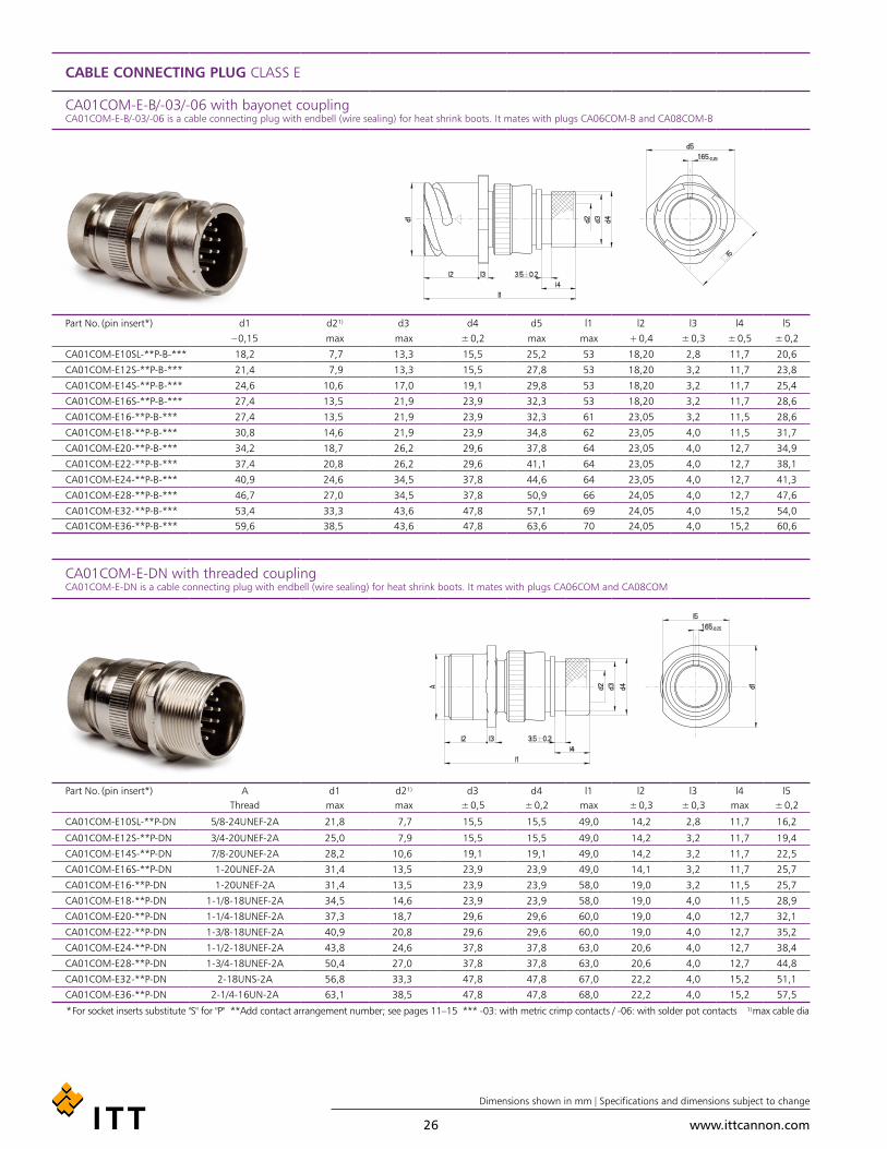
CABLE CONNECTING PLUG CLASS E
CA01COM-E-B/-03/-06 with bayonet coupling CA01COM-E-B/-03/-06 is a cable connecting plug with endbell (wire sealing) for heat shrink boots. It mates with plugs CA06COM-B and CA08COM-B
Part No. (pin insert*) d1 d2¹) d3 d4 d5 l1 l2 l3 l4 l5– 0,15 max max ± 0,2 max max + 0,4 ± 0,3 ± 0,5 ± 0,2
CA01COM-E10SL-**P-B-*** 18,2 7,7 13,3 15,5 25,2 53 18,20 2,8 11,7 20,6
CA01COM-E12S-**P-B-*** 21,4 7,9 13,3 15,5 27,8 53 18,20 3,2 11,7 23,8
CA01COM-E14S-**P-B-*** 24,6 10,6 17,0 19,1 29,8 53 18,20 3,2 11,7 25,4
CA01COM-E16S-**P-B-*** 27,4 13,5 21,9 23,9 32,3 53 18,20 3,2 11,7 28,6
CA01COM-E16-**P-B-*** 27,4 13,5 21,9 23,9 32,3 61 23,05 3,2 11,5 28,6
CA01COM-E18-**P-B-*** 30,8 14,6 21,9 23,9 34,8 62 23,05 4,0 11,5 31,7
CA01COM-E20-**P-B-*** 34,2 18,7 26,2 29,6 37,8 64 23,05 4,0 12,7 34,9
CA01COM-E22-**P-B-*** 37,4 20,8 26,2 29,6 41,1 64 23,05 4,0 12,7 38,1
CA01COM-E24-**P-B-*** 40,9 24,6 34,5 37,8 44,6 64 23,05 4,0 12,7 41,3
CA01COM-E28-**P-B-*** 46,7 27,0 34,5 37,8 50,9 66 24,05 4,0 12,7 47,6
CA01COM-E32-**P-B-*** 53,4 33,3 43,6 47,8 57,1 69 24,05 4,0 15,2 54,0CA01COM-E36-**P-B-*** 59,6 38,5 43,6 47,8 63,6 70 24,05 4,0 15,2 60,6
CA01COM-E-DN with threaded coupling CA01COM-E-DN is a cable connecting plug with endbell (wire sealing) for heat shrink boots. It mates with plugs CA06COM and CA08COM
Part No. (pin insert*) A d1 d2¹) d3 d4 l1 l2 l3 l4 l5Thread max max ± 0,5 ± 0,2 max ± 0,3 ± 0,3 max ± 0,2
CA01COM-E10SL-**P-DN 5/8-24UNEF-2A 21,8 7,7 15,5 15,5 49,0 14,2 2,8 11,7 16,2
CA01COM-E12S-**P-DN 3/4-20UNEF-2A 25,0 7,9 15,5 15,5 49,0 14,2 3,2 11,7 19,4
CA01COM-E14S-**P-DN 7/8-20UNEF-2A 28,2 10,6 19,1 19,1 49,0 14,2 3,2 11,7 22,5
CA01COM-E16S-**P-DN 1-20UNEF-2A 31,4 13,5 23,9 23,9 49,0 14,1 3,2 11,7 25,7
CA01COM-E16-**P-DN 1-20UNEF-2A 31,4 13,5 23,9 23,9 58,0 19,0 3,2 11,5 25,7
CA01COM-E18-**P-DN 1-1/8-18UNEF-2A 34,5 14,6 23,9 23,9 58,0 19,0 4,0 11,5 28,9
CA01COM-E20-**P-DN 1-1/4-18UNEF-2A 37,3 18,7 29,6 29,6 60,0 19,0 4,0 12,7 32,1
CA01COM-E22-**P-DN 1-3/8-18UNEF-2A 40,9 20,8 29,6 29,6 60,0 19,0 4,0 12,7 35,2
CA01COM-E24-**P-DN 1-1/2-18UNEF-2A 43,8 24,6 37,8 37,8 63,0 20,6 4,0 12,7 38,4
CA01COM-E28-**P-DN 1-3/4-18UNEF-2A 50,4 27,0 37,8 37,8 63,0 20,6 4,0 12,7 44,8
CA01COM-E32-**P-DN 2-18UNS-2A 56,8 33,3 47,8 47,8 67,0 22,2 4,0 15,2 51,1
CA01COM-E36-**P-DN 2-1/4-16UN-2A 63,1 38,5 47,8 47,8 68,0 22,2 4,0 15,2 57,5
* For socket inserts substitute "S" for "P" **Add contact arrangement number; see pages 11–15 *** -03: with metric crimp contacts / -06: with solder pot contacts ¹) max cable dia

www.ittcannon.com
Dimensions shown in mm | Specifications and dimensions subject to change
27
CABLE CONNECTING PLUG CLASS F
CA01COM-F-B with bayonet coupling CA01COM-F-B is a cable connecting plug for flex tube. It mates with plugs CA06COM-B and CA08COM-B
Part No. (pin insert*) d1 d2¹) d3 d4 l1 l2 l3 l4 l5– 0,15 Thread max max + 0,4 ± 0,2 min ± 0,2
CA01COM-F10SL-**P-B-*** 18,2 8,2 5/8-24UNEF-2A 25,2 50 18,20 2,8 9,5 20,6
CA01COM-F12S-**P-B-*** 18,2 8,2 5/8-20UNEF-2A 27,8 50 18,20 3,2 9,5 23,8
CA01COM-F14S-**P-B-*** 24,6 11,1 3/4-20UNEF-2A 29,8 50 18,20 3,2 9,5 25,4
CA01COM-F16S-**P-B-*** 27,4 14,3 7/8-20UNEF-2A 32,3 50 18,20 3,2 9,5 28,6
CA01COM-F16-**P-B-*** 27,4 14,3 7/8-20UNEF-2A 32,3 57 23,05 3,2 9,5 28,6
CA01COM-F18-**P-B-*** 30,8 16,7 1-20UNEF-2A 34,8 59 23,05 4,0 9,5 31,7
CA01COM-F20-**P-B-*** 34,2 19,8 1-3/16-18UNEF-2A 37,8 59 23,05 4,0 9,5 34,9
CA01COM-F22-**P-B-*** 37,4 19,8 1-3/16-18UNEF-2A 41,1 62 23,05 4,0 9,5 38,1
CA01COM-F24-**P-B-*** 40,9 25,4 1-7/16-18UNEF-2A 44,6 62 23,05 4,0 9,5 41,3
CA01COM-F28-**P-B-*** 46,7 27,0 1-7/16-18UNEF-2A 50,9 64 24,05 4,0 9,5 47,6
CA01COM-F32-**P-B-*** 53,4 32,5 1-3/4-18UNS-2A 57,1 64 24,05 4,0 11,0 54,0CA01COM-F36-**P-B-*** 59,6 35,7 2-18UNS-2A 63,6 66 24,05 4,0 11,8 60,6
CA01COM-F with threaded coupling CA01COM-F is a cable connecting plug for flex tube. It mates with plugs CA06COM and CA08COM
Part No. (pin insert*) A d1 d2¹) d3 l1 l2 l3 l4 l5Thread max Thread max + 0,4 ± 0,3 min ± 0,2
CA01COM-F10SL-**P-*** 5/8-24UNEF-2A 21,8 8,2 5/8-24UNEF-2A 45 14,2 2,8 9,5 16,2
CA01COM-F12S-**P-*** 3/4-20UNEF-2A 25,0 8,2 5/8-20UNEF-2A 45 14,2 3,2 9,5 19,4
CA01COM-F14S-**P-*** 7/8-20UNEF-2A 28,2 11,1 3/4-20UNEF-2A 45 14,2 3,2 9,5 22,5
CA01COM-F16S-**P-*** 1-20UNEF-2A 31,4 14,3 7/8-20UNEF-2A 45 14,2 3,2 9,5 25,7
CA01COM-F16-**P-*** 1-20UNEF-2A 31,4 14,3 7/8-20UNEF-2A 54 14,2 3,2 9,5 25,7
CA01COM-F18-**P-*** 1-1/8-18UNEF-2A 34,5 16,7 1-20UNEF-2A 54 19,0 4,0 9,5 28,9
CA01COM-F20-**P-*** 1-1/4-18UNEF-2A 37,3 19,8 1-3/16-18UNEF-2A 55 19,0 4,0 9,5 32,1
CA01COM-F22-**P-*** 1-3/8-18UNEF-2A 40,9 19,8 1-3/16-18UNEF-2A 58 20,6 4,0 9,5 35,2
CA01COM-F24-**P-*** 1-1/2-18UNEF-2A 43,8 25,4 1-7/16-18UNEF-2A 59 20,6 4,0 9,5 38,4
CA01COM-F28-**P-*** 1-3/4-18UNEF-2A 50,4 27,0 1-7/16-18UNEF-2A 60 20,6 4,0 9,5 44,8
CA01COM-F32-**P-*** 2-18UNS-2A 56,8 32,5 1-3/4-18UNS-2A 62 22,2 4,0 11,0 51,1
CA01COM-F36-**P-*** 2-1/4-16UN-2A 63,1 35,7 2-18UNS-2A 64 22,2 4,0 11,8 57,5
* For socket inserts substitute "S" for "P" **Add contact arrangement number; see pages 11–15 *** Add modification code; see page 10 (bottom) ¹) max cable dia

www.ittcannon.com
Dimensions shown in mm | Specifications and dimensions subject to change
28
BOX MOUNTING RECEPTACLE CLASS E
CA02COM-E-B with bayonet coupling CA02COM-E-B is a box mounting receptacle for front panel mounting. It mates with plugs CA06COM-B and CA08COM-B
Part No. (pin insert*) d1 d2 d3 l1 l2 l3 l4 e– 0,15 H13 max. ± 0,3 + 0,4 ± 0,2 ± 0,3 ± 0,1
CA02COM-E10SL-**-P-B-*** 18,2 3.1 16,2 24,7 14,2 2,8 25,4 18,2
CA02COM-E12S-**-P-B-*** 21,4 3.1 16,2 24,7 14,2 3,2 28,0 20,6
CA02COM-E14S-**-P-B-*** 24,6 3.1 19,2 24,7 14,2 3,2 30,0 23,0
CA02COM-E16S-**-P-B-*** 27,4 3.1 22,4 24,7 14,2 3,2 32,5 24,6
CA02COM-E16-**-P-B-*** 27,4 3.1 22,4 33,8 19,0 3,2 32,5 24,6
CA02COM-E18-**-P-B-*** 30,8 3.1 25,6 33,8 19,0 4,0 35,0 27,0
CA02COM-E20-**-P-B-*** 34,2 3.1 29,0 33,8 19,0 4,0 38,0 29,4
CA02COM-E22-**-P-B-*** 37,4 3.1 32,2 33,8 19,0 4,0 41,0 31,8
CA02COM-E24-**-P-B-*** 40,9 3.7 35,3 33,8 20,6 4,0 44,5 34,9
CA02COM-E28-**-P-B-*** 46,7 3.7 41,4 33,8 20,6 4,0 50,8 39,7
CA02COM-E32-**-P-B-*** 53,4 4.4 47,8 33,8 22,2 4,0 57,0 44,5CA02COM-E36-**-P-B-*** 59,6 4.4 52,6 33,8 22,2 4,0 63,5 49,2
CA02COM-E with threaded coupling CA02COM-E is a boxmounting receptacle for front panel mounting. It mates with plugs CA06COM and CA08COM
Part No. (pin insert*) A d1 d2 l1 l2 l3 l4 eThread max. + 0,2 max. + 0,4 ± 0,3 ± 0,3 ± 0,1
CA02COM-E10SL-**-P-*** 5/8-24UNEF-2A 15,9 3,1 25,1 14,2 2,8 25,4 18,2
CA02COM-E12S-**-P-*** 3/4-20UNEF-2A 15,9 3,1 25,1 14,2 3,2 28,0 20,6
CA02COM-E14S-**-P-*** 7/8-20UNEF-2A 19,0 3,1 25,1 14,2 3,2 30,0 23,0
CA02COM-E16S-**-P-*** 1-20UNEF-2A 22,2 3,1 25,1 14,2 3,2 32,5 24,6
CA02COM-E16-**-P-*** 1-20UNEF-2A 22,2 3,1 34,2 19,0 3,2 32,5 24,6
CA02COM-E18-**-P-*** 1-1/8-18UNEF-2A 25,4 3,1 34,2 19,0 4,0 35,0 27,0
CA02COM-E20-**-P-*** 1-1/4-18UNEF-2A 29,0 3,1 34,2 19,0 4,0 38,0 29,4
CA02COM-E22-**-P-*** 1-3/8-18UNEF-2A 32,2 3,1 34,2 19,0 4,0 41,0 31,8
CA02COM-E24-**-P-*** 1-1/2-18UNEF-2A 35,3 3,7 34,2 20,6 4,0 44,5 34,9
CA02COM-E28-**-P-*** 1-3/4-18UNEF-2A 41,2 3,7 34,2 20,6 4,0 50,8 39,7
CA02COM-E32-**-P-*** 2-18UNS-2A 47,6 4,4 34,2 22,2 4,0 57,0 44,5
CA02COM-E36-**-P-*** 2-1/4-16UN-2A 52,4 4,4 34,2 22,2 4,0 63,5 49,2
* For socket inserts substitute "S" for "P" **Add contact arrangement number; see pages 11–15 *** Add modification code; see page 10 (bottom) ¹) max cable dia
www.ittcannon.com
Dimensions shown in mm | Specifications and dimensions subject to change
29
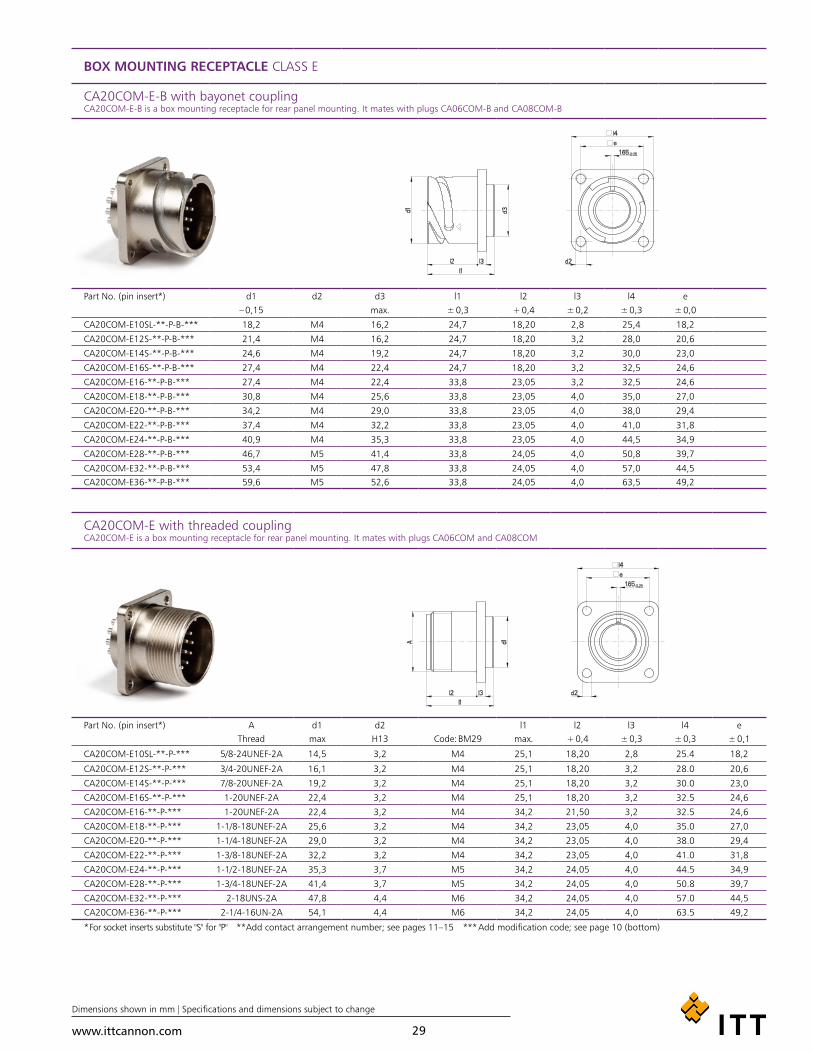
BOX MOUNTING RECEPTACLE CLASS E
CA20COM-E-B with bayonet coupling CA20COM-E-B is a box mounting receptacle for rear panel mounting. It mates with plugs CA06COM-B and CA08COM-B
Part No. (pin insert*) d1 d2 d3 l1 l2 l3 l4 e– 0,15 max. ± 0,3 + 0,4 ± 0,2 ± 0,3 ± 0,0
CA20COM-E10SL-**-P-B-*** 18,2 M4 16,2 24,7 18,20 2,8 25,4 18,2
CA20COM-E12S-**-P-B-*** 21,4 M4 16,2 24,7 18,20 3,2 28,0 20,6
CA20COM-E14S-**-P-B-*** 24,6 M4 19,2 24,7 18,20 3,2 30,0 23,0
CA20COM-E16S-**-P-B-*** 27,4 M4 22,4 24,7 18,20 3,2 32,5 24,6
CA20COM-E16-**-P-B-*** 27,4 M4 22,4 33,8 23,05 3,2 32,5 24,6
CA20COM-E18-**-P-B-*** 30,8 M4 25,6 33,8 23,05 4,0 35,0 27,0
CA20COM-E20-**-P-B-*** 34,2 M4 29,0 33,8 23,05 4,0 38,0 29,4
CA20COM-E22-**-P-B-*** 37,4 M4 32,2 33,8 23,05 4,0 41,0 31,8
CA20COM-E24-**-P-B-*** 40,9 M4 35,3 33,8 23,05 4,0 44,5 34,9
CA20COM-E28-**-P-B-*** 46,7 M5 41,4 33,8 24,05 4,0 50,8 39,7
CA20COM-E32-**-P-B-*** 53,4 M5 47,8 33,8 24,05 4,0 57,0 44,5CA20COM-E36-**-P-B-*** 59,6 M5 52,6 33,8 24,05 4,0 63,5 49,2
CA20COM-E with threaded coupling CA20COM-E is a box mounting receptacle for rear panel mounting. It mates with plugs CA06COM and CA08COM
Part No. (pin insert*) A d1 d2 l1 l2 l3 l4 eThread max H13 Code: BM29 max. + 0,4 ± 0,3 ± 0,3 ± 0,1
CA20COM-E10SL-**-P-*** 5/8-24UNEF-2A 14,5 3,2 M4 25,1 18,20 2,8 25.4 18,2
CA20COM-E12S-**-P-*** 3/4-20UNEF-2A 16,1 3,2 M4 25,1 18,20 3,2 28.0 20,6
CA20COM-E14S-**-P-*** 7/8-20UNEF-2A 19,2 3,2 M4 25,1 18,20 3,2 30.0 23,0
CA20COM-E16S-**-P-*** 1-20UNEF-2A 22,4 3,2 M4 25,1 18,20 3,2 32.5 24,6
CA20COM-E16-**-P-*** 1-20UNEF-2A 22,4 3,2 M4 34,2 21,50 3,2 32.5 24,6
CA20COM-E18-**-P-*** 1-1/8-18UNEF-2A 25,6 3,2 M4 34,2 23,05 4,0 35.0 27,0
CA20COM-E20-**-P-*** 1-1/4-18UNEF-2A 29,0 3,2 M4 34,2 23,05 4,0 38.0 29,4
CA20COM-E22-**-P-*** 1-3/8-18UNEF-2A 32,2 3,2 M4 34,2 23,05 4,0 41.0 31,8
CA20COM-E24-**-P-*** 1-1/2-18UNEF-2A 35,3 3,7 M5 34,2 24,05 4,0 44.5 34,9
CA20COM-E28-**-P-*** 1-3/4-18UNEF-2A 41,4 3,7 M5 34,2 24,05 4,0 50.8 39,7
CA20COM-E32-**-P-*** 2-18UNS-2A 47,8 4,4 M6 34,2 24,05 4,0 57.0 44,5
CA20COM-E36-**-P-*** 2-1/4-16UN-2A 54,1 4,4 M6 34,2 24,05 4,0 63.5 49,2
* For socket inserts substitute "S" for "P" **Add contact arrangement number; see pages 11–15 *** Add modification code; see page 10 (bottom)
www.ittcannon.com
Dimensions shown in mm | Specifications and dimensions subject to change
30
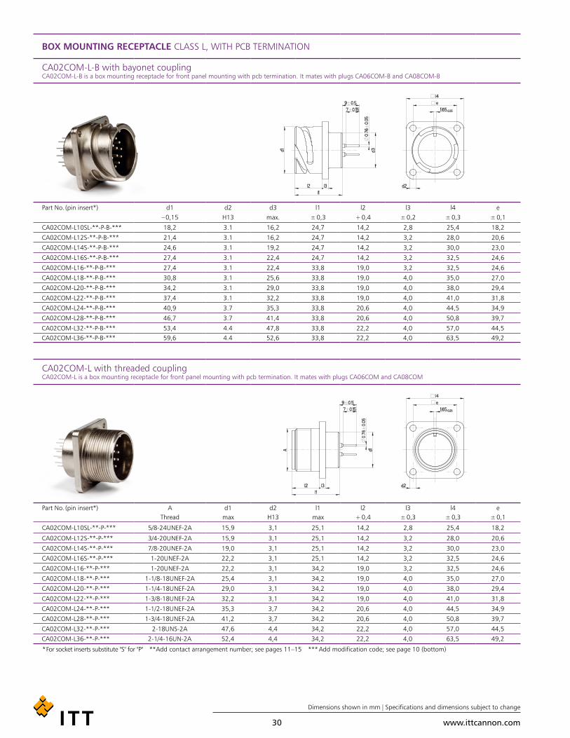
BOX MOUNTING RECEPTACLE CLASS L, WITH PCB TERMINATION
CA02COM-L-B with bayonet coupling CA02COM-L-B is a box mounting receptacle for front panel mounting with pcb termination. It mates with plugs CA06COM-B and CA08COM-B
Part No. (pin insert*) d1 d2 d3 l1 l2 l3 l4 e– 0,15 H13 max. ± 0,3 + 0,4 ± 0,2 ± 0,3 ± 0,1
CA02COM-L10SL-**-P-B-*** 18,2 3.1 16,2 24,7 14,2 2,8 25,4 18,2
CA02COM-L12S-**-P-B-*** 21,4 3.1 16,2 24,7 14,2 3,2 28,0 20,6
CA02COM-L14S-**-P-B-*** 24,6 3.1 19,2 24,7 14,2 3,2 30,0 23,0
CA02COM-L16S-**-P-B-*** 27,4 3.1 22,4 24,7 14,2 3,2 32,5 24,6
CA02COM-L16-**-P-B-*** 27,4 3.1 22,4 33,8 19,0 3,2 32,5 24,6
CA02COM-L18-**-P-B-*** 30,8 3.1 25,6 33,8 19,0 4,0 35,0 27,0
CA02COM-L20-**-P-B-*** 34,2 3.1 29,0 33,8 19,0 4,0 38,0 29,4
CA02COM-L22-**-P-B-*** 37,4 3.1 32,2 33,8 19,0 4,0 41,0 31,8
CA02COM-L24-**-P-B-*** 40,9 3.7 35,3 33,8 20,6 4,0 44,5 34,9
CA02COM-L28-**-P-B-*** 46,7 3.7 41,4 33,8 20,6 4,0 50,8 39,7
CA02COM-L32-**-P-B-*** 53,4 4.4 47,8 33,8 22,2 4,0 57,0 44,5CA02COM-L36-**-P-B-*** 59,6 4.4 52,6 33,8 22,2 4,0 63,5 49,2
CA02COM-L with threaded coupling CA02COM-L is a box mounting receptacle for front panel mounting with pcb termination. It mates with plugs CA06COM and CA08COM
Part No. (pin insert*) A d1 d2 l1 l2 l3 l4 eThread max H13 max + 0,4 ± 0,3 ± 0,3 ± 0,1
CA02COM-L10SL-**-P-*** 5/8-24UNEF-2A 15,9 3,1 25,1 14,2 2,8 25,4 18,2
CA02COM-L12S-**-P-*** 3/4-20UNEF-2A 15,9 3,1 25,1 14,2 3,2 28,0 20,6
CA02COM-L14S-**-P-*** 7/8-20UNEF-2A 19,0 3,1 25,1 14,2 3,2 30,0 23,0
CA02COM-L16S-**-P-*** 1-20UNEF-2A 22,2 3,1 25,1 14,2 3,2 32,5 24,6
CA02COM-L16-**-P-*** 1-20UNEF-2A 22,2 3,1 34,2 19,0 3,2 32,5 24,6
CA02COM-L18-**-P-*** 1-1/8-18UNEF-2A 25,4 3,1 34,2 19,0 4,0 35,0 27,0
CA02COM-L20-**-P-*** 1-1/4-18UNEF-2A 29,0 3,1 34,2 19,0 4,0 38,0 29,4
CA02COM-L22-**-P-*** 1-3/8-18UNEF-2A 32,2 3,1 34,2 19,0 4,0 41,0 31,8
CA02COM-L24-**-P-*** 1-1/2-18UNEF-2A 35,3 3,7 34,2 20,6 4,0 44,5 34,9
CA02COM-L28-**-P-*** 1-3/4-18UNEF-2A 41,2 3,7 34,2 20,6 4,0 50,8 39,7
CA02COM-L32-**-P-*** 2-18UNS-2A 47,6 4,4 34,2 22,2 4,0 57,0 44,5
CA02COM-L36-**-P-*** 2-1/4-16UN-2A 52,4 4,4 34,2 22,2 4,0 63,5 49,2
* For socket inserts substitute "S" for "P" **Add contact arrangement number; see pages 11–15 *** Add modification code; see page 10 (bottom)
www.ittcannon.com
Dimensions shown in mm | Specifications and dimensions subject to change
31
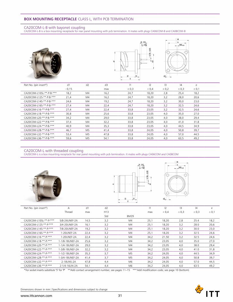
BOX MOUNTING RECEPTACLE CLASS L, WITH PCB TERMINATION
CA20COM-L-B with bayonet coupling CA20COM-L-B is a box mounting receptacle for rear panel mounting with pcb termination. It mates with plugs CA06COM-B and CA08COM-B
Part No. (pin insert*) d1 d2 d3 l1 l2 l3 l4 e– 0,15 max ± 0,3 + 0,4 ± 0,2 ± 0,3 ± 0,1
CA20COM-L10SL-**-P-B-*** 18,2 M4 16,2 24,7 18,20 2,8 25,4 18,2
CA20COM-L12S-**-P-B-*** 21,4 M4 16,2 24,7 18,20 3,2 28,0 20,6
CA20COM-L14S-**-P-B-*** 24,6 M4 19,2 24,7 18,20 3,2 30,0 23,0
CA20COM-L16S-**-P-B-*** 27,4 M4 22,4 24,7 18,20 3,2 32,5 24,6
CA20COM-L16-**-P-B-*** 27,4 M4 22,4 33,8 23,05 3,2 32,5 24,6
CA20COM-L18-**-P-B-*** 30,8 M4 25,6 33,8 23,05 4,0 35,0 27,0
CA20COM-L20-**-P-B-*** 34,2 M4 29,0 33,8 23,05 4,0 38,0 29,4
CA20COM-L22-**-P-B-*** 37,4 M4 32,2 33,8 23,05 4,0 41,0 31,8
CA20COM-L24-**-P-B-*** 40,9 M4 35,3 33,8 23,05 4,0 44,5 34,9
CA20COM-L28-**-P-B-*** 46,7 M5 41,4 33,8 24,05 4,0 50,8 39,7
CA20COM-L32-**-P-B-*** 53,4 M5 47,8 33,8 24,05 4,0 57,0 44,5CA20COM-L36-**-P-B-*** 59,6 M5 54,1 33,8 24,05 4,0 63,5 49,2
CA20COM-L with threaded coupling CA20COM-L is a box mounting receptacle for rear panel mounting with pcb termination. It mates with plugs CA06COM and CA08COM
Part No. (pin insert*) A d1 d2 l1 l2 l3 l4 eThread max H13 max + 0,4 ± 0,3 ± 0,3 ± 0,1
Std BM29
CA20COM-L10SL-**-P-*** 5/8-24UNEF-2A 14,5 3,2 M4 25,1 18,20 2,8 25.4 18,2
CA20COM-L12S-**-P-*** 3/4-20UNEF-2A 16,1 3,2 M4 25,1 18,20 3,2 28.0 20,6
CA20COM-L14S-**-P-*** 7/8-20UNEF-2A 19,2 3,2 M4 25,1 18,20 3,2 30.0 23,0
CA20COM-L16S-**-P-*** 1-20UNEF-2A 22,4 3,2 M4 25,1 18,20 3,2 32.5 24,6
CA20COM-L16-**-P-*** 1-20UNEF-2A 22,4 3,2 M4 34,2 21,50 3,2 32.5 24,6
CA20COM-L18-**-P-*** 1-1/8-18UNEF-2A 25,6 3,2 M4 34,2 23,05 4,0 35.0 27,0
CA20COM-L20-**-P-*** 1-1/4-18UNEF-2A 29,0 3,2 M4 34,2 23,05 4,0 38.0 29,4
CA20COM-L22-**-P-*** 1-3/8-18UNEF-2A 32,2 3,2 M4 34,2 23,05 4,0 41.0 31,8
CA20COM-L24-**-P-*** 1-1/2-18UNEF-2A 35,3 3,7 M5 34,2 24,05 4,0 44.5 34,9
CA20COM-L28-**-P-*** 1-3/4-18UNEF-2A 41,4 3,7 M5 34,2 24,05 4,0 50.8 39,7
CA20COM-L32-**-P-*** 2-18UNS-2A 47,8 4,4 M6 34,2 24,05 4,0 57.0 44,5
CA20COM-L36-**-P-*** 2-1/4-16UN-2A 54,1 4,4 M6 34,2 24,05 4,0 63.5 49,2
* For socket inserts substitute "S" for "P" **Add contact arrangement number; see pages 11–15 *** Add modification code; see page 10 (bottom)

www.ittcannon.com
Dimensions shown in mm | Specifications and dimensions subject to change
32
STRAIGHT PLUG PG OR METRIC ADAPTER
CA06COM-PG/ME-B with bayonet coupling CA06COM-PG/ME-B is a straight plug for usage of PG and metric terminations. It mates with receptacles CA00COM-B, CA01COM-B, CA02COM-E-B and CA20COM-E-B
Part No. (pin insert*) d1 d2 l1max PG-Thread Metric max
CA06COM-PG10SL-**P-B-*** CA06COM-ME10SL-*P-B-*** 22,8 PG9 M16 × 1,5 52,0
CA06COM-PG12S-**P-B-*** CA06COM-ME12S-**P-B-*** 26,0 PG9 M16 × 1,5 52,0
CA06COM-PG14S-**P-B-*** CA06COM-ME14S-**P-B-*** 29,2 PG11 M20 × 1,5 52,0
CA06COM-PG16S-**P-B-*** CA06COM-ME16S-*P-B-*** 32,0 PG13,5 M20 × 1,5 54,0
CA06COM-PG16-**P-B-*** CA06COM-ME16-**P-B-*** 32,0 PG13,5 M20 × 1,5 64,0
CA06COM-PG18-**P-B-*** CA06COM-ME18-**P-B-*** 36,5 PG13,5 M25 × 1,5 69,0
CA06COM-PG20-**P-B-*** CA06COM-ME20-**P-B-*** 39,9 PG16 M25 × 1,5 70,0
CA06COM-PG22-**P-B-*** CA06COM-ME22-**P-B-*** 42,1 PG16 M32 × 1,5 73,0
CA06COM-PG24-**P-B-*** CA06COM-ME24-**P-B-*** 46,6 PG16 M32 × 1,5 74,0
CA06COM-PG28-**P-B-*** CA06COM-ME28-**P-B-*** 53,4 PG21 M32 × 1,5 74,0
CA06COM-PG32-**P-B-*** CA06COM-ME32-**P-B-*** 60,1 PG29 M40 × 1,5 76,0CA06COM-PG36-**P-B-*** CA06COM-ME36-**P-B-*** 66,3 PG29 M40 × 1,5 87,0
CA06COM-PG/ME with threaded coupling CA06COM-PG/ME is a straight plug for usage of PG and metric terminations.It mates with receptacles CA00COM, CA01COM, CA02COM-E and CA20COM-E
Part No. (pin insert*) A d1 d2 l1Thread max PG-Thread Metric max
CA06COM-PG10SL-**P-*** CA06COM-ME10SL-*P-*** 5/8-24UNEF-2B 24,1 PG9 M16 × 1,5 52,0
CA06COM-PG12S-**P-*** CA06COM-ME12S-**P-*** 3/4-20UNEF-2B 25,8 PG9 M16 × 1,5 52,0
CA06COM-PG14S-**P-*** CA06COM-ME14S-**P-*** 7/8-20UNEF-2B 28,8 PG11 M20 × 1,5 52,0
CA06COM-PG16S-**P-*** CA06COM-ME16S-*P-*** 1-20UNEF-2B 31,8 PG13,5 M20 × 1,5 54,0
CA06COM-PG16-**P-*** CA06COM-ME16-**P-*** 1-20UNEF-2B 31,8 PG13,5 M20 × 1,5 64,0
CA06COM-PG18-**P-*** CA06COM-ME18-**P-*** 1-1/8-18UNEF-2B 34,1 PG13,5 M25 × 1,5 69,0
CA06COM-PG20-**P-*** CA06COM-ME20-**P-*** 1-1/4-18UNEF-2B 37,4 PG16 M25 × 1,5 70,0
CA06COM-PG22-**P-*** CA06COM-ME22-**P-*** 1-3/8-18UNEF-2B 40,5 PG16 M32 × 1,5 73,0
CA06COM-PG24-**P-*** CA06COM-ME24-**P-*** 1-1/2-18UNEF-2B 43,8 PG16 M32 × 1,5 74,0
CA06COM-PG28-**P-*** CA06COM-ME28-**P-*** 1-3/4-18UNEF-2B 50,2 PG21 M32 × 1,5 74,0
CA06COM-PG32-**P-*** CA06COM-ME32-**P-*** 2-18UNS-2B 56,4 PG29 M40 × 1,5 76,0
CA06COM-PG36-**P-*** CA06COM-ME36-**P-*** 2-1/4-16UN-2B 62,8 PG29 M40 × 1,5 87,0
* For socket inserts substitute "S" for "P" **Add contact arrangement number; see pages 11–15 *** Add modification code; see page 10 (bottom)

www.ittcannon.com
Dimensions shown in mm | Specifications and dimensions subject to change
33
STRAIGHT PLUG CLASS E
CA06COM-E-B with bayonet coupling CA06COM-E-B is a straight plug with endbell and cable clamp. It mates with receptacles CA00COM-B CA01COM-B, CA02COM-E-B and CA20COM-E-B
Part No. (pin insert*) d1 d2¹) l1max. max.
CA06COM-E10SL-**P-B-*** 22,8 7,9 53
CA06COM-E12S-**P-B-*** 26,0 7,9 53
CA06COM-E14S-**P-B-*** 29,2 11,1 55
CA06COM-E16S-**P-B-*** 32,0 14,2 56
CA06COM-E16-**P-B-*** 32,0 14,2 66
CA06COM-E18-**P-B-*** 36,5 15,8 68
CA06COM-E20-**P-B-*** 39,9 19,0 68
CA06COM-E22-**P-B-*** 43,1 19,0 68
CA06COM-E24-**P-B-*** 46,6 23,7 76
CA06COM-E28-**P-B-*** 53,4 23,7 76
CA06COM-E32-**P-B-*** 60,1 31,8 76CA06COM-E36-**P-B-*** 66,3 34,6 76
CA06COM-E with threaded coupling CCA06COM-E is a straight plug with endbell and cable clamp. It mates with receptacles CA00COM, CA01COM, CA02COM-E and CA20COM-E
Part No. (pin insert*) A d1 d2¹) l1Thread max max. max.
CA06COM-E10SL-**P-*** 5/8-24UNEF-2B 24,1 7,9 53
CA06COM-E12S-**P-*** 3/4-20UNEF-2B 25,8 7,9 53
CA06COM-E14S-**P-*** 7/8-20UNEF-2B 28,8 11,1 55
CA06COM-E16S-**P-*** 1-20UNEF-2B 31,8 14,2 56
CA06COM-E16-**P-*** 1-20UNEF-2B 31,8 14,2 66
CA06COM-E18-**P-*** 1-1/8-18UNEF-2B 34,1 15,8 68
CA06COM-E20-**P-*** 1-1/4-18UNEF-2B 37,4 19,0 68
CA06COM-E22-**P-*** 1-3/8-18UNEF-2B 40,5 19,0 68
CA06COM-E24-**P-*** 1-1/2-18UNEF-2B 43,8 23,7 76
CA06COM-E28-**P-*** 1-3/4-18UNS-2B 50,2 23,7 76
CA06COM-E32-**P-*** 2-18UNS-2B 56,4 31,8 76
CA06COM-E36-**P-*** 2-1/4-16UN-2B 62,8 34,6 76
* For socket inserts substitute "S" for "P" **Add contact arrangement number; see pages 11–15 *** Add modification code; see page 10 (bottom) ¹) max cable dia

www.ittcannon.com
Dimensions shown in mm | Specifications and dimensions subject to change
34
STRAIGHT PLUG CLASS F
CA06COM-F-B with bayonet coupling CA06COM-F-B is a straight plug with endbell for flex tubes. It mates with receptacles CA00COM-B, CA01COM-B, CA02COM-E-B and CA20COM-E-B
Part No. (pin insert*) d1 d2¹) l2 l1max max min max
CA06COM-F10SL-**P-B-*** 22,8 8,2 9,5 45
CA06COM-F12S-**P-B-*** 26,0 8,2 9,5 45
CA06COM-F14S-**P-B-*** 29,2 11,1 9,5 45
CA06COM-F16S-**P-B-*** 32,0 14,3 9,5 45
CA06COM-F16-**P-B-*** 32,0 14,3 9,5 54
CA06COM-F18-**P-B-*** 36,5 16,7 9,5 54
CA06COM-F20-**P-B-*** 39,9 19,8 9,5 55
CA06COM-F22-**P-B-*** 43,1 19,8 9,5 58
CA06COM-F24-**P-B-*** 46,6 25,4 9,5 59
CA06COM-F28-**P-B-*** 53,4 27,0 9,5 59
CA06COM-F32-**P-B-*** 60,1 32,5 11,0 62CA06COM-F36-**P-B-*** 66,3 35,7 11,8 64
CA06COM-F with threaded coupling CA06COM-F is a straight plug with endbell for flex tubes. It mates with receptacles CA00COM, CA01COM, CA02COM-E and CA20COM-E
Part No. (pin insert*) A d1 d2¹) d3 l1 l2Thread max Thread max min
CA06COM-F10SL-**P-*** 5/8-24UNEF-2B 24,1 8,2 5/8-24UNEF-2A 45 9,5
CA06COM-F12S-**P-*** 3/4-20UNEF-2B 25,8 8,2 5/8-20UNEF-2A 45 9,5
CA06COM-F14S-**P-*** 7/8-20UNEF-2B 28,8 11,1 3/4-20UNEF-2A 45 9,5
CA06COM-F16S-**P-*** 1-20UNEF-2B 31,8 14,3 7/8-20UNEF-2A 45 9,5
CA06COM-F16-**P-*** 1-20UNEF-2B 31,8 14,3 7/8-20UNEF-2A 54 9,5
CA06COM-F18-**P-*** 1-1/8-18UNEF-2B 34,1 16,7 1-20UNEF-2A 54 9,5
CA06COM-F20-**P-*** 1-1/4-18UNEF-2B 37,4 19,8 1-3/16-18UNEF-2A 55 9,5
CA06COM-F22-**P-*** 1-3/8-18UNEF-2B 40,5 19,8 1-3/16-18UNEF-2A 58 9,5
CA06COM-F24-**P-*** 1-1/2-18UNEF-2B 43,8 25,4 1-7/16-18UNEF-2A 59 9,5
CA06COM-F28-**P-*** 1-3/4-18UNEF-2B 50,2 27,0 1-7/16-18UNEF-2A 60 9,5
CA06COM-F32-**P-*** 2-18UNS-2B 56,4 32,5 1-3/4-18UNS-2A 62 11,0
CA06COM-F36-**P-*** 2-1/4-16UN-2B 62,8 35,7 2-18UNS-2A 64 11,8
* For socket inserts substitute "S" for "P" **Add contact arrangement number; see pages 11–15 *** Add modification code; see page 10 (bottom) ¹) max cable dia

www.ittcannon.com
Dimensions shown in mm | Specifications and dimensions subject to change
35
STRAIGHT PLUG CLASS E
CA06COM-E-B /-03/-06 with bayonet coupling CA06COM-E-B /-03/-06 is a straight plug with endbell (wire sealing) for heat shrink boots. It mates with receptacles CA00COM-B, CA01COM-B, CA02COM-E-B and CA20COM-E-B
Part No. (pin insert*) d1 d2¹) d3 d4 l1 l2max max ± 0,2 max ± 0,5
CA06COM-E10SL-**P-B-*** 22,8 7,7 13,3 15,5 49 11,7
CA06COM-E12S-**P-B-*** 26,0 7,9 13,3 15,5 49 11,7
CA06COM-E14S-**P-B-*** 29,2 10,6 17,0 19,1 49 11,7
CA06COM-E16S-**P-B-*** 32,0 13,5 21,9 23,9 49 11,7
CA06COM-E16-**P-B-*** 32,0 13,5 21,9 23,9 58 11,5
CA06COM-E18-**P-B-*** 36,5 14,6 21,9 23,9 58 11,5
CA06COM-E20-**P-B-*** 39,9 18,7 26,2 29,6 60 12,7
CA06COM-E22-**P-B-*** 43,1 20,8 26,2 29,6 60 12,7
CA06COM-E24-**P-B-*** 46,6 24,6 34,5 37,8 63 12,7
CA06COM-E28-**P-B-*** 53,4 27,0 34,5 37,8 63 12,7
CA06COM-E32-**P-B-*** 60,1 33,3 43,6 47,8 67 15,2CA06COM-E36-**P-B-*** 66,3 38,5 43,6 47,8 68 15,2
CA06COM-E-DN with threaded coupling CA06COM-E-DN is a straight plug with endbell (wire sealing) for heat shrink boots. It mates with receptacles CA00COM, CA01COM and CA02COM-E and CA20COM-E
Part No. (pin insert*) A d1 d2¹) d3 d4 l1 l2Thread max max max ± 0,2 max ± 0,5
CA06COM-E10SL-**P-DN 5/8-24UNEF-2B 24,1 7,7 13,3 15,5 49 11,7
CA06COM-E12S-**P-DN 3/4-20UNEF-2B 25,8 7,9 13,3 15,5 49 11,7
CA06COM-E14S-**P-DN 7/8-20UNEF-2B 28,8 10,6 17,0 19,1 49 11,7
CA06COM-E16S-**P-DN 1-20UNEF-2B 31,8 13,5 21,9 23,9 49 11,7
CA06COM-E16-**P-DN 1-20UNEF-2B 31,8 13,5 21,9 23,9 58 11,5
CA06COM-E18-**P-DN 1-1/8-18UNEF-2B 34,1 14,6 21,9 23,9 58 11,5
CA06COM-E20-**P-DN 1-1/4-18UNEF-2B 37,4 18,7 26,2 29,6 60 12,7
CA06COM-E22-**P-DN 1-3/8-18UNEF-2B 40,5 20,8 26,2 29,6 60 12,7
CA06COM-E24-**P-DN 1-1/2-18UNEF-2B 43,8 24,6 34,5 37,8 63 12,7
CA06COM-E28-**P-DN 1-3/4-18UNEF-2B 50,2 27,0 34,5 37,8 63 12,7
CA06COM-E32-**P-DN 2-18UNS-2B 56,4 33,3 43,6 47,8 67 15,2
CA06COM-E36-**P-DN 2-1/4-16UN-2B 62,8 38,5 43,6 47,8 68 15,2
* For socket inserts substitute "S" for "P" **Add contact arrangement number; see pages 11–15 *** -03: with metric crimp contacts, -06: with solder pot contacts ¹) max cable dia
www.ittcannon.com
Dimensions shown in mm | Specifications and dimensions subject to change
36
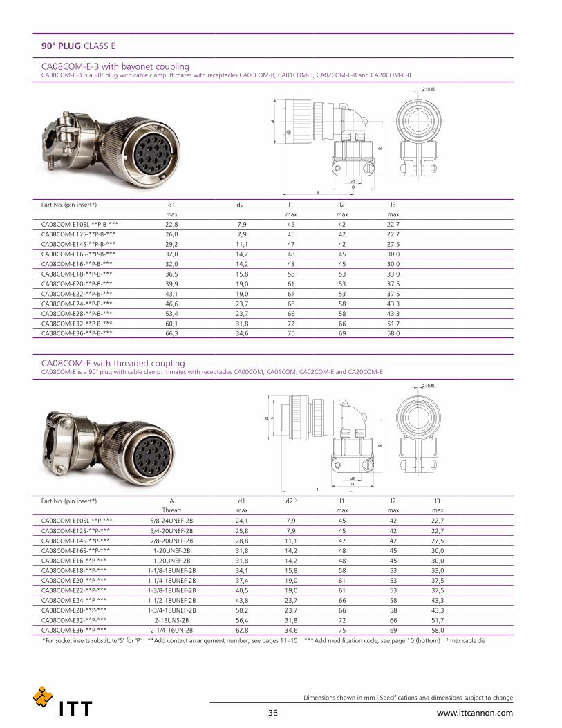
90° PLUG CLASS E
CA08COM-E-B with bayonet coupling CA08COM-E-B is a 90° plug with cable clamp. It mates with receptacles CA00COM-B, CA01COM-B, CA02COM-E-B and CA20COM-E-B
Part No. (pin insert*) d1 d2¹) l1 l2 l3max max max max
CA08COM-E10SL-**P-B-*** 22,8 7,9 45 42 22,7
CA08COM-E12S-**P-B-*** 26,0 7,9 45 42 22,7
CA08COM-E14S-**P-B-*** 29,2 11,1 47 42 27,5
CA08COM-E16S-**P-B-*** 32,0 14,2 48 45 30,0
CA08COM-E16-**P-B-*** 32,0 14,2 48 45 30,0
CA08COM-E18-**P-B-*** 36,5 15,8 58 53 33,0
CA08COM-E20-**P-B-*** 39,9 19,0 61 53 37,5
CA08COM-E22-**P-B-*** 43,1 19,0 61 53 37,5
CA08COM-E24-**P-B-*** 46,6 23,7 66 58 43,3
CA08COM-E28-**P-B-*** 53,4 23,7 66 58 43,3
CA08COM-E32-**P-B-*** 60,1 31,8 72 66 51,7CA08COM-E36-**P-B-*** 66,3 34,6 75 69 58,0
CA08COM-E with threaded coupling CA08COM-E is a 90° plug with cable clamp. It mates with receptacles CA00COM, CA01COM, CA02COM-E and CA20COM-E
Part No. (pin insert*) A d1 d2¹) l1 l2 l3Thread max max max max
CA08COM-E10SL-**P-*** 5/8-24UNEF-2B 24,1 7,9 45 42 22,7
CA08COM-E12S-**P-*** 3/4-20UNEF-2B 25,8 7,9 45 42 22,7
CA08COM-E14S-**P-*** 7/8-20UNEF-2B 28,8 11,1 47 42 27,5
CA08COM-E16S-**P-*** 1-20UNEF-2B 31,8 14,2 48 45 30,0
CA08COM-E16-**P-*** 1-20UNEF-2B 31,8 14,2 48 45 30,0
CA08COM-E18-**P-*** 1-1/8-18UNEF-2B 34,1 15,8 58 53 33,0
CA08COM-E20-**P-*** 1-1/4-18UNEF-2B 37,4 19,0 61 53 37,5
CA08COM-E22-**P-*** 1-3/8-18UNEF-2B 40,5 19,0 61 53 37,5
CA08COM-E24-**P-*** 1-1/2-18UNEF-2B 43,8 23,7 66 58 43,3
CA08COM-E28-**P-*** 1-3/4-18UNEF-2B 50,2 23,7 66 58 43,3
CA08COM-E32-**P-*** 2-18UNS-2B 56,4 31,8 72 66 51,7
CA08COM-E36-**P-*** 2-1/4-16UN-2B 62,8 34,6 75 69 58,0
* For socket inserts substitute "S" for "P" **Add contact arrangement number; see pages 11–15 *** Add modification code; see page 10 (bottom) ¹) max cable dia

www.ittcannon.com
Dimensions shown in mm | Specifications and dimensions subject to change
37
90° PLUG CLASS F
CA08COM-F-B with bayonet coupling CA08COM-F-B is a 90° plug for flex tubes. It mates with receptacles CA00COM-B, CA01COM-B, CA02COM-E-B and CA20COM-E-B
Part No. (pin insert*) d1 d2 l1 l2 l3max Thread max min max
CA08COM-F10SL-**P-B-*** 22,8 5/8-24UNEF-2B 45 9,4 22,0
CA08COM-F12S-**P-B-*** 26,0 5/8-20UNEF-2B 45 9,4 22,0
CA08COM-F14S-**P-B-*** 29,2 3/4-20UNEF-2B 47 9,4 24,0
CA08COM-F16S-**P-B-*** 32,0 7/8-20UNEF-2B 48 9,4 25,0
CA08COM-F16-**P-B-*** 32,0 7/8-20UNEF-2B 57 9,4 25,0
CA08COM-F18-**P-B-*** 36,5 1-20UNEF-2B 58 9,4 27,0
CA08COM-F20-**P-B-*** 39,9 1-3/16-18UNEF-2B 61 9,4 29,0
CA08COM-F22-**P-B-*** 43,1 1-3/16-18UNEF-2B 61 9,4 30,0
CA08COM-F24-**P-B-*** 46,6 1-7/16-18UNEF-2B 66 9,4 32,0
CA08COM-F28-**P-B-*** 53,4 1-7/16-18UNEF-2B 66 9,4 34,0
CA08COM-F32-**P-B-*** 60,1 1-3/4-18UNS-2B 72 11,0 39,5CA08COM-F36-**P-B-*** 66,3 2-18UNS-2B 75 12,6 45,0
CA08COM-F with threaded coupling CA08COM-F is a 90° plug for flex tubes. It mates with receptacles CA00COM, CA01COM, CA02COM-E and CA20COM-E
Part No. (pin insert*) A d1 d2 l1 l2 l3Thread max Thread max min max
CA08COM-F10SL-**P-*** 5/8-24UNEF-2B 24,1 5/8-24UNEF-2A 45 9,4 22,0
CA08COM-F12S-**P-*** 3/4-20UNEF-2B 25,8 5/8-20UNEF-2A 45 9,4 22,0
CA08COM-F14S-**P-*** 7/8-20UNEF-2B 28,8 3/4-20UNEF-2A 47 9,4 24,0
CA08COM-F16S-**P-*** 1-20UNEF-2B 31,8 7/8-20UNEF-2A 48 9,4 25,0
CA08COM-F16-**P-*** 1-20UNEF-2B 31,8 7/8-20UNEF-2A 48 9,4 25,0
CA08COM-F18-**P-*** 1-1/8-18UNEF-2B 34,1 1-20UNEF-2A 58 9,4 27,0
CA08COM-F20-**P-*** 1-1/4-18UNEF-2B 37,4 1-3/16-18UNEF-2A 61 9,4 29,0
CA08COM-F22-**P-*** 1-3/8-18UNEF-2B 40,5 1-3/16-18UNEF-2A 61 9,4 30,0
CA08COM-F24-**P-*** 1-1/2-18UNEF-2B 43,8 1-7/16-18UNEF-2A 66 9,4 32,0
CA08COM-F28-**P-*** 1-3/4-18UNEF-2B 50,2 1-7/16-18UNEF-2A 66 9,4 34,0
CA08COM-F32-**P-*** 2-18UNS-2B 56,4 1-3/4-18UNS-2A 72 11,0 39,5
CA08COM-F36-**P-*** 2-1/4-16UN-2B 62,8 2-18UNS-2A 75 12,6 45,0
* For socket inserts substitute "S" for "P" **Add contact arrangement number; see pages 11–15 *** Add modification code; see page 10 (bottom)

www.ittcannon.com
Dimensions shown in mm | Specifications and dimensions subject to change
38
90° PLUG CLASS PG (METRIC THREAD OPTION UNAVAILABLE)
CA08COM-PG-B with bayonet coupling CA08COM-PG-B designates a 90º plug for usage of PG terminations. It mates with receptacles CA00COM-B, CA01COM-B, CA02COM-E-B and CA20COM-E-B
Part No. (pin insert*) d1 d2 l1 l2max. max ± 0,5
CA08COM-E10SL-**P-B-*** 22.8 PG9 57 18.5
CA08COM-E12S-**P-B-*** 26.0 PG9 57 18.5
CA08COM-E14S-**P-B-*** 29.2 PG11 59 19.5
CA08COM-E16S-**P-B-*** 32.0 PG13,5 63 22.0
CA08COM-E16-**P-B-*** 32.0 PG13,5 72 22.0
CA08COM-E18-**P-B-*** 36.5 PG16 77 26.3
CA08COM-E20-**P-B-*** 39.9 PG21 82 29.0
CA08COM-E22-**P-B-*** 43.1 PG21 82 29.5
CA08COM-PG with threaded coupling CA08COM-PG designates a 90º plug for usage of PG terminations. It mates with receptacles CA00COM, CA01COM, CA02COM-E and CA20COM
Part No. (pin insert*) A d1 d2 l1 l2Thread max. max ± 0,5
CA08COM-E10SL-**P-*** 5/8-24UNEF-2B 24.1 PG9 57 18.5
CA08COM-E12S-**P-*** 3/4-20UNEF-2B 25.8 PG9 57 18.5
CA08COM-E14S-**P-*** 7/8-20UNEF-2B 28.8 PG11 59 19.5
CA08COM-E16S-**P-*** 1-20UNEF-2B 31.8 PG13,5 63 22.0
CA08COM-E16-**P-*** 1-20UNEF-2B 31.8 PG13,5 72 22.0
CA08COM-E18-**P-*** 1-1/8-20UNEF-2B 34.1 PG16 77 26.3
CA08COM-E20-**P-*** 1-1/4-20UNEF-2B 37.4 PG21 82 29.0
CA08COM-E22-**P-*** 1-3/8-20UNEF-2B 40.5 PG21 82 29.5
* For socket inserts substitute "S" for "P" **Add contact arrangement number; see pages 11–15 *** Add modification code; see page 10 (bottom) ¹) max cable dia

www.ittcannon.com
Dimensions shown in mm | Specifications and dimensions subject to change
39
ACCESSORIES
PROTECTIVE CAPS with cord for receptacles with bayonet coupling. It mates with receptacles CA00COM-B, CA01COM-E-B and CA02COM-E-B CA20COM-E-B
Part No. Shell size d1 l1 l2 Tmax ± 10 max + 0,25
CA121003-1701 10SL 22.4 100 16 4.3
CA121003-1702 12S 25.6 100 16 4.3
CA121003-1703 14S 28.8 100 16 4.3
CA121003-1704 16S 31.6 100 16 4.3
CA121003-1705 16 31.6 113 16 4.3
CA121003-1706 18 35.7 113 16 4.3
CA121003-1707 20 39.1 127 16 4.3
CA121003-1708 22 42.3 127 16 4.3
CA121003-1709 24 45.8 127 16 4.3
CA121003-1710 28 51.6 169 18 5.5
CA121003-1711 32 58.3 169 18 5.5CA121003-1712 36 64.5 169 18 5.5
PROTECTIVE CAPS with cord for receptacles with threaded coupling. It mates with receptacles CA00COM, CA01COM and CA02COM and CA20COM
Part No. Shell size A d1 l1 l2 T
Thread max max max + 0,2
CA121003-1601 10 SL 5/8-24UNEF-2B 20.2 100 16,0 3.6
CA121003-1602 12S 3/4-20UNEF-2B 23,4 120 16,0 3.6
CA121003-1603 14S 7/8-20UNEF-2B 26.6 120 16,0 3.6
CA121003-1604 16S,16 1-20UNEF-2B 29.8 120 16,0 3.6
CA121003-1606 18 1-1/8-18UNEF-2B 32.9 120 16,0 3.6
CA121003-1607 20 1-1/4-18UNEF-2B 36.1 125 16,0 3.6
CA121003-1608 22 1-3/8-18UNEF-2B 39.4 125 16,0 3.6
CA121003-1609 24 1-1/2-18UNEF-2B 42.6 140 16,0 4.4
CA121003-1610 28 1-3/4-18UNEF-2B 48.9 200 18,0 4.4
CA121003-1611 32 2-18UNS-2B 55.3 200 18,0 4.8
CA121003-1612 36 2-1/4-16UN-2B 61.6 200 18,0 4.8
www.ittcannon.com
Dimensions shown in mm | Specifications and dimensions subject to change
40
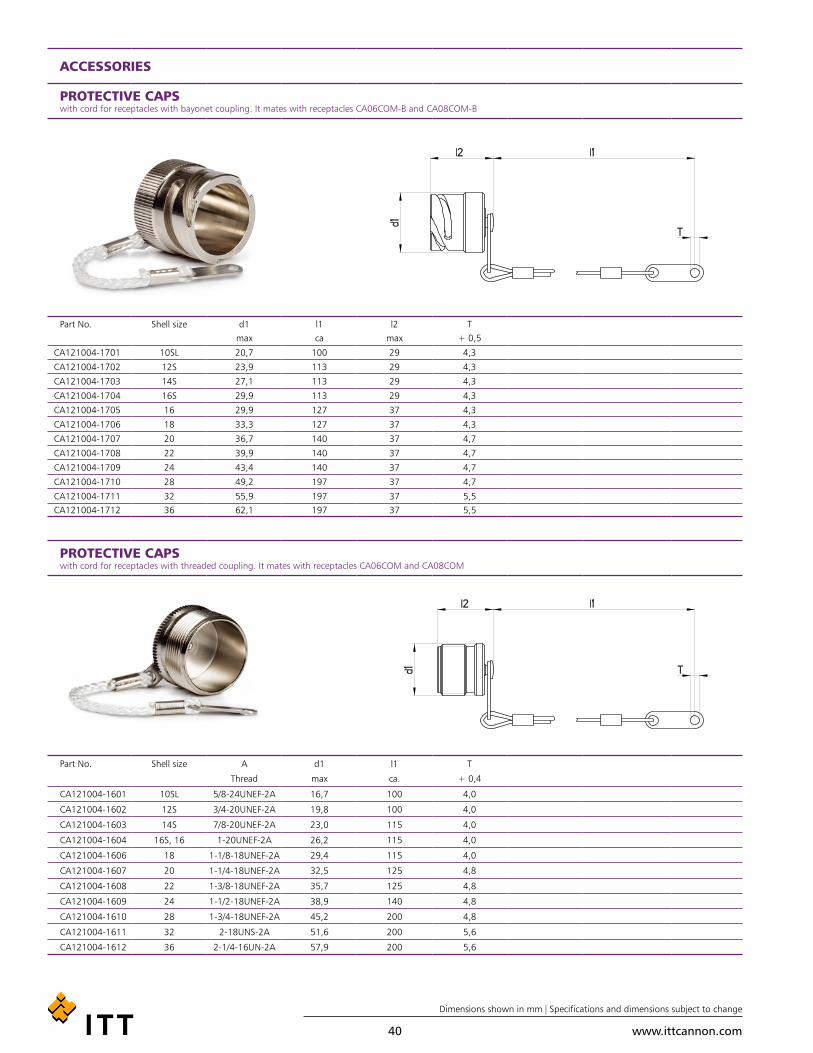
ACCESSORIES
PROTECTIVE CAPS with cord for receptacles with bayonet coupling. It mates with receptacles CA06COM-B and CA08COM-B
Part No. Shell size d1 l1 l2 Tmax ca max + 0,5
CA121004-1701 10SL 20,7 100 29 4,3
CA121004-1702 12S 23,9 113 29 4,3
CA121004-1703 14S 27,1 113 29 4,3
CA121004-1704 16S 29,9 113 29 4,3
CA121004-1705 16 29,9 127 37 4,3
CA121004-1706 18 33,3 127 37 4,3
CA121004-1707 20 36,7 140 37 4,7
CA121004-1708 22 39,9 140 37 4,7
CA121004-1709 24 43,4 140 37 4,7
CA121004-1710 28 49,2 197 37 4,7
CA121004-1711 32 55,9 197 37 5,5CA121004-1712 36 62,1 197 37 5,5
PROTECTIVE CAPS with cord for receptacles with threaded coupling. It mates with receptacles CA06COM and CA08COM
Part No. Shell size A d1 l1 T
Thread max ca. + 0,4
CA121004-1601 10SL 5/8-24UNEF-2A 16,7 100 4,0
CA121004-1602 12S 3/4-20UNEF-2A 19,8 100 4,0
CA121004-1603 14S 7/8-20UNEF-2A 23,0 115 4,0
CA121004-1604 16S, 16 1-20UNEF-2A 26,2 115 4,0
CA121004-1606 18 1-1/8-18UNEF-2A 29,4 115 4,0
CA121004-1607 20 1-1/4-18UNEF-2A 32,5 125 4,8
CA121004-1608 22 1-3/8-18UNEF-2A 35,7 125 4,8
CA121004-1609 24 1-1/2-18UNEF-2A 38,9 140 4,8
CA121004-1610 28 1-3/4-18UNEF-2A 45,2 200 4,8
CA121004-1611 32 2-18UNS-2A 51,6 200 5,6
CA121004-1612 36 2-1/4-16UN-2A 57,9 200 5,6

www.ittcannon.com
Dimensions shown in mm | Specifications and dimensions subject to change
41
ACCESSORIES
CABLE CLAMP WITHOUT BUSHING
Part No. Shell size A d1 l1 l2Thread max max max
CA121051-325 10SL, 12S 5/8-24UNEF-2B 7,9 20,8 22,5
CA121051-326 14S 3/4-20UNEF-2B 11,1 22,4 27,4
CA121051-327 16S, 16 7/8-20UNEF-2B 14,2 24,0 29,8
CA121051-328 18 1-20UNEF-2B 15,8 24,0 32,2
CA121051-329 20, 22 1-3/16-18UNEF-2B 19,0 24,0 37,4
CA121051-330 24, 28 1-7/16-18UNEF-2B 23,7 26,4 43,5
CA121051-331 32 1-3/4-18UNS-2B 31,8 28,0 51,7CA121051-332 36 2-18UNS-2B 34,6 29,6 57,8
TELESCOPING BUSHING The telescoping bushing is used together with above cable clamps CA121051-… or the other E type cable clamp connectors. It keeps oil, dirt or dust out of the endbell. Taping or wrapping or insulating of the wires feed through the clamp is eliminated since they are protected by the bushing. Combinations of bushings may be used to reduce cable entry diameters for improved sealing.
Part No. Shell size d1 d2 d3 l1
- 0,3 - 0,3 max max
012-8552-000 10SL, 12S 8,0 6,6 9,9 70
012-8554-000 14S 10,9 9,1 12,7 67
012-0218-000 16S, 16 14,0 11,1 19,0 64
012-0219-000 18 15,7 14,3 22,0 60
012-0220-000 20, 22 18,8 15,9 26,9 57
012-8555-000 24, 28 21,2 16,6 26,9 57
012-8556-000 24, 28 23,6 21,5 33,3 54
012-8557-000 32 26,5 21,5 33,3 54
012-8558-000 32 31,5 26,8 40,4 51
012-8558-000 36 31,5 26,8 40,4 51
012-0223-000 36 34,7 31,8 46,8 48

www.ittcannon.com
Dimensions shown in mm | Specifications and dimensions subject to change
42
ACCESSORIES
GASKETS These sealing gaskets made of neoprene are used with receptacles with flange for sealing between the shell and the flange of the receptacle
Gaskets for CA00COM-B / CA20COM-B (Rear panel mounting bayonet)
Part No. Shell size d1 d2 l e+ 0,3 + 0,5 ± 0,5 ± 0,2
075-8501-000 10SL 18,2 4,2 25,4 18,2
075-8502-000 12S 21,4 4,2 28,0 20,6
075-8503-000 14S 24,6 4,2 30,0 23,0
075-8504-000 16S, 16 27,4 4,2 32,5 24,6
075-8505-000 18 30,8 4,2 35,0 27,0
075-8506-000 20 34,2 4,2 38,0 29,4
075-8507-000 22 37,4 4,2 41,0 31,8
075-8508-000 24 40,9 4,2 44,5 34,9
075-8509-000 28 46,7 5,1 50,8 39,7
075-8510-000 32 53,4 5,1 57,0 44,5
075-8511-000 36 59,6 5,1 63,5 49,2
Gaskets for CA00COM / CA02COM / CA02COM-B
Part No. Shell size d1 d2 l e
+ 1,0 + 0,5 ± 0,5 ± 0,2
075-8512-000 10SL 15,7 4,2 25,4 18,2
075-8513-000 12S 18,9 4,2 28,0 20,6
075-8514-000 14S 22,1 4,2 30,0 23,0
075-8515-000 16S, 16 25,3 4,2 32,5 24,6
075-8516-000 18 28,4 4,2 35,0 27,0
075-8517-000 20 31,6 4,2 38,0 29,4
075-8518-000 22 34,8 4,2 41,0 31,8
075-8519-000 24 38,0 4,2 44,5 34,9
075-8520-000 28 44,3 5,1 50,8 39,7
075-8521-000 32 50,7 5,1 57,0 44,5
075-8522-000 36 57,0 5,1 63,5 49,2
www.ittcannon.com
Dimensions shown in mm | Specifications and dimensions subject to change
43
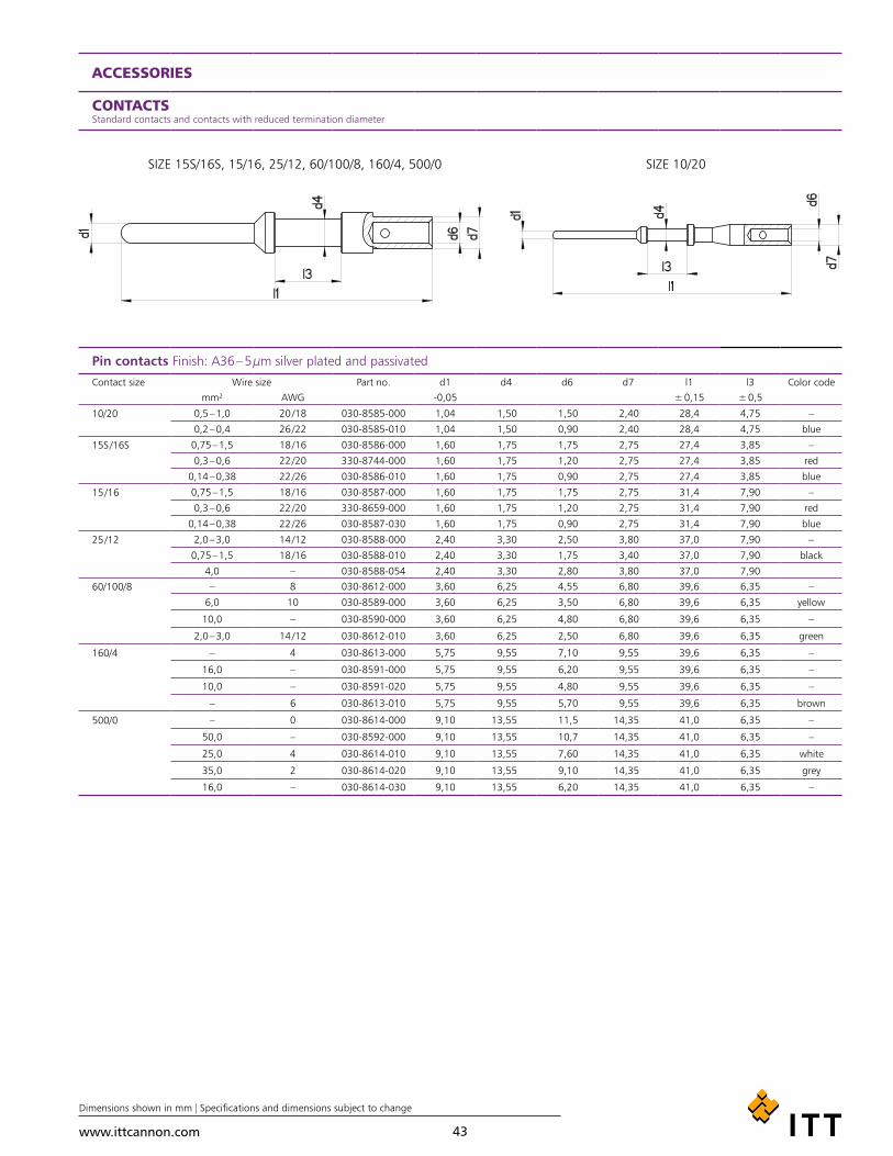
ACCESSORIES
CONTACTS Standard contacts and contacts with reduced termination diameter
Pin contacts Finish: A36 – 5 µm silver plated and passivated
Contact size Wire size Part no. d1 d4 d6 d7 l1 l3 Color codemm² AWG -0,05 ± 0,15 ± 0,5
10/20 0,5 – 1,0 20 /18 030-8585-000 1,04 1,50 1,50 2,40 28,4 4,75 –
0,2 – 0,4 26 /22 030-8585-010 1,04 1,50 0,90 2,40 28,4 4,75 blue
15S /16S 0,75 – 1,5 18 /16 030-8586-000 1,60 1,75 1,75 2,75 27,4 3,85 –
0,3 – 0,6 22 /20 330-8744-000 1,60 1,75 1,20 2,75 27,4 3,85 red
0,14 – 0,38 22 /26 030-8586-010 1,60 1,75 0,90 2,75 27,4 3,85 blue
15 /16 0,75 – 1,5 18 /16 030-8587-000 1,60 1,75 1,75 2,75 31,4 7,90 –
0,3 – 0,6 22 /20 330-8659-000 1,60 1,75 1,20 2,75 31,4 7,90 red
0,14 – 0,38 22 /26 030-8587-030 1,60 1,75 0,90 2,75 31,4 7,90 blue
25 /12 2,0 – 3,0 14 /12 030-8588-000 2,40 3,30 2,50 3,80 37,0 7,90 –
0,75 – 1,5 18 /16 030-8588-010 2,40 3,30 1,75 3,40 37,0 7,90 black
4,0 – 030-8588-054 2,40 3,30 2,80 3,80 37,0 7,90
60/100/8 – 8 030-8612-000 3,60 6,25 4,55 6,80 39,6 6,35 –
6,0 10 030-8589-000 3,60 6,25 3,50 6,80 39,6 6,35 yellow
10,0 – 030-8590-000 3,60 6,25 4,80 6,80 39,6 6,35 –
2,0 – 3,0 14 /12 030-8612-010 3,60 6,25 2,50 6,80 39,6 6,35 green
160/4 – 4 030-8613-000 5,75 9,55 7,10 9,55 39,6 6,35 –
16,0 – 030-8591-000 5,75 9,55 6,20 9,55 39,6 6,35 –
10,0 – 030-8591-020 5,75 9,55 4,80 9,55 39,6 6,35 –
– 6 030-8613-010 5,75 9,55 5,70 9,55 39,6 6,35 brown
500/0 – 0 030-8614-000 9,10 13,55 11,5 14,35 41,0 6,35 –
50,0 – 030-8592-000 9,10 13,55 10,7 14,35 41,0 6,35 –
25,0 4 030-8614-010 9,10 13,55 7,60 14,35 41,0 6,35 white
35,0 2 030-8614-020 9,10 13,55 9,10 14,35 41,0 6,35 grey
16,0 – 030-8614-030 9,10 13,55 6,20 14,35 41,0 6,35 –
SIZE 15S/16S, 15/16, 25/12, 60/100/8, 160/4, 500/0 SIZE 10/20

www.ittcannon.com
Dimensions shown in mm | Specifications and dimensions subject to change
44
ACCESSORIES
CONTACTS Standard contacts and contacts with reduced termination diameter
Socket contacts Finish: A36 – 5 µm silver plated and passivated
Contact size Wire size Part no. d1 d2 d3 d5 d6 l1 l3 Color codemm² AWG + 0,05 ± 0,2 ± 0,1
10/20 0,5 –1,0 20/18 031-8554-000 2,0 1,07 1,5 1,5 2,4 36,8 ± 0,3 4,75 –
0,2 – 0,4 26/22 031-8554-010 2,0 1,07 1,5 0,9 2,4 36,8 ± 0,3 4,75 blue
15S /16S 0,75 –1,5 18 /16 031-8555-110 3,2 1,65 1,75 1,75 2,75 29,1 3,9 –
0,3 – 0,6 22/20 031-8688-110 3,2 1,65 1,75 1,2 2,75 29,1 3,9 red
0,14 – 0,38 22/26 031-8555-130 3,2 1,65 1,75 0,9 2,75 29,1 3,9 blue
15 /16 0,75 –1,5 18 /16 031-8556-110 3,2 1,65 1,75 1,75 2,75 37,8 7,9 –0,3 – 0,6 22/20 031-8639-120 3,2 1,65 1,75 1,2 2,75 37,8 7,9 red
0,14 – 0,38 22/26 031-8556-130 3,2 1,65 1,75 0,9 2,75 37,8 7,9 blue
25 /12 2,0 – 3,0 14/12 031-8557-000 4,8 2,45 3,3 2,5 3,8 37,0 7,9 –
0,75 –1,5 18/16 031-8557-020 4,8 2,45 3,3 1,75 3,4 37,0 7,9 black
4,0 – 031-8557-010 4,8 2,45 3,3 2,8 3,8 37,0 7,9 –0,3 – 0,6 22/20 031-8557-040 4,8 2,45 3,3 1,2 2,75 37,0 7,9 –
60/100/8 – 8 031-8519-000 6,5 3,65 6,25 4,55 6,8 40,1 6,35 –
6,0 10 031-8558-000 6,5 3,65 6,25 3,5 6,8 40,1 6,35 yellow
10,0 – 031-8559-000 6,5 3,65 6,25 4,8 6,8 40,1 6,35 –
2,0 – 3,0 14 /12 031-8519-010 6,5 3,65 6,25 2,5 6,8 40,1 6,35 green
160/4 – 4 031-8520-000 8,6 5,8 9,55 7,1 9,55 40,1 6,35 –
16,0 – 031-8560-000 8,6 5,8 9,55 6,2 9,55 40,1 6,35 –
10,0 – 031-8560-020 8,6 5,8 9,55 4,8 9,55 40,1 6,35 –
– 6 031-8520-010 8,6 5,8 9,55 5,7 9,55 40,1 6,35 brown
500/0 – 0 031-8521-000 13,2 9,15 13,55 11,5 14,35 41,6 6,35 –
50,0 – 031-8561-000 13,2 9,15 13,55 10,7 14,35 41,6 6,35 –
25,0 4 031-8521-010 13,2 9,15 13,55 7,6 14,35 41,6 6,35 white
35,0 2 031-8521-020 13,2 9,15 13,55 9,1 14,35 41,6 6,35 grey
16,0 – 031-8521-030 13,2 9,15 13,55 6,2 14,35 41,6 6,35 –
Remark:For Socket contact installation the following guiding pins are essential:
Contact size Part numberguide pin # 15/16 and 15S /16 27977-16T50guide pin # 12/25 27977-12T8
SIZE 10/20 SIZE 25/12
SIZE 15S/16S 15/16
SIZE 60/100/8 160/4 500/0

www.ittcannon.com
Dimensions shown in mm | Specifications and dimensions subject to change
45
ACCESSORIES
TOOLING FOR CONTACT CRIMPING AND INSTALLATION
HAND CRIMP TOOL M22520-1-01 PART NUMBER 995-0001-585
Contact size Wire size Crimp Locator Order Referencemm² AWG
10/20 0,5 – 1,0 20 /18
600325 (mod. TH 452) 121586-0034
0,2 – 0,4 26 /22
Pin 15S /16S 0,75 – 1,5 18 /16
0,3 – 0,6 22 /200,14 – 0,38 22 /26
Socket 15S /S16 0,75 – 1,5 18 /16
600324 (mod. TH 452) 121586-00330,3 – 0,6 22 /20
0,14 – 0,38 22 /2615/16 0,75 – 1,5 18 /16
TH 452 995-0002-052
0,3 – 0,6 22 /20
0,14 – 0,38 22 /26
25 /12 2,0 – 3,0 14 /12
0,75 – 1,5 18 /16
4,0 –
HYDRAULIC HANDCRIMP TOOL HPW400U-ITT PART NUMBER 121586-5257
Contact size Wire size Specificsmm² AWG
60/100/8 6,0 8 The hydraulic handcrimp tool HPW400U-ITT is delivered without crimp dies. Please order your specific crimp dies seperately, on page 44
2,0 – 3,0 10
– 14 /12
160/4 16,0 4
10,0 6
500/0 – 0
50,0 –
25,0 4
35,0 2
16,0 –
ELECTRO HYDRAULIC TOOL HP700EL-ITT PART NUMBER 121586-5279
Contact size Wire size Specifics
mm² AWG
60/100/8 6,0 8 The electro-hydraulic tool HP700EL-ITT is delivered with an H-crimp head (table mount), foot pedal and hand control. Please order crimp dies as well as switch mode power supply or lithium-ion battery separately - details below.
2,0 – 3,0 10
– 14 /12
160/4 16,0 4
10,0 6
500/0 – 0
50,0 –
25,0 4
35,0 2
16,0 –
ACCESSORIES FOR ELECTR HYDRAULIC CRIMP TOOL HP700EL-ITT PART NUMBER 121586-5279
Description Marking Part Number
Switch mode power supply SNT4-ITT 121586-5280
Lithium Ion Battery 18V 3A with recharger LGA4-ITT 121586-5281

www.ittcannon.com
Dimensions shown in mm | Specifications and dimensions subject to change
46
ACCESSORIES
TOOLING FOR CONTACT INSERTION AND EXTRACTION
INSERTION AND EXTRACTION TOOLSInsertion Tools
Type CIT 20 CIT 16 CIT12 CIT 8 CIT 4 CIT 0Part No. 121086-3009 121086-3008 121086-3007 121086-0095 121086-0094 121086-0093
Insertion Pliers
Type CIT-F80-20 CIT-F80-16 CIT-F80-12Part No. 121086-0098 121086-0097 121086-0096
Extraction Tools
Type CET-F80-20 CET-F80-16 CET-F80-12 CET-8 CET-4 CET-0
Part No. 121086-0082 121086-0081 121086-0080 121086-0079 121086-0078 121086-0077
CRIMP DIES FOR MS/CA, VG95234
Contact size Wire size Hex. Diameter Stamped Label Part Numbermm² AWG
60/100/8 6/10 8 5,20 01 121586-5231
160/4 16 4 7,25 02 121586-5230
500/0 50,0 0 11,40 03 121586-5229
Locator for MS/CA, part number 121586-5232
Notes:1. For large series production, semi-automatic crimp machine Type HACS-IV-MSXX upon request2. For insertion and extraction of the contacts and for connector assembly see "Assembly instructions SAE-AS50151/VG952343. Standard contacts acc. to SAE-AS50151/VG95234

www.ittcannon.com 47
PRODUCT SAFETY INFORMATION
1. MATERIAL CONTENT AND PHYSICAL FORM
Electrical connectors do not usually contain hazardous materials. They contain conducting and non-conducting materials and can be divided into two groups.a) Printed circuit types and low cost audio types which employ all plastic insulators and casings.b) Rugged, Fire Barrier and High Reliability types with metal casings and either natural rubber, synthetic rubber, plastic or glass insulating materials. Contact materials vary with type of connector and also application and are usually manufactured from either: Copper, copper alloys, nickel, alumel, chromel or steel. In special applications, other alloys may be specified.
2. FIRE CHARACTERISTICS AND ELECTRIC SHOCK HAZARD
There is no fire hazard when the connector is correctly wired and used within the specified parameters. Incorrect wiring or assembly of the connector or careless use of metal tools or conductive fluids, or transit damage to any of the component parts may cause electric shock or burns. Live circuits must not be broken by separating mated connectors as this may cause arcing, ionization and burning. Heat dissipation is greater at maximum resistance in a circuit. Hot spots may occur when resistance is raised locally by damage, e.g. cracked or deformed contacts, broken strands of wire. Local overheating may also result from the use of the incorrect applica-tion tools or from poor quality soldering or slack screw terminals. Overheating may occur if the ratings in the product Data Sheet/Catalog are exceeded and can cause breakdown of insulation and hence electric shock. If heating is allowed to continue it intensifies by further increasing the local resistance through loss of temper of spring contacts, formation of oxide film on contacts and wires and leakage currents through carbonization of insulation and tracking paths. Fire can then result in the presence of combustible materials and this may release noxious fumes. Overheating may not be visually apparent. Burns may result from touching overheated components.
3. HANDLINGCare must be taken to avoid damage to any component parts of electrical connectors during installation and use. Although there are normally no sharp edges, care must be taken when handling certain components to avoid injury to fingers.
Electrical connectors may be damaged in transit to the customers, and damage may result in creation of hazards. Products should therefore be examined prior to instal-lation/use and rejected if found to be damaged.
4. DISPOSALIncineration of certain materials may release noxious or even toxic fumes.
5. APPLICATIONConnectors with exposed contacts should not be selected for use on the current supply side of an electrical circuit, because an elec-tric shock could result from touching exposed contacts on an unmated connector. Voltages in excess of 30 V ac or 42.5 V DC are potentially hazardous and care should be taken to ensure that such voltages cannot be transmitted in any way to exposed metal parts of the connector body. The connector and wiring should be checked, before making live, to have no damage to metal parts or insulators, no solder blobs, loose strands, conducting lubricants, swarf, or any other undesired conducting particles. Circuit resistance and continuity check should be made to make certain that there are no high resistance joints or spurious conducting paths. Always use the correct application tools as specified in the Data Sheet/Catalog. Do not permit untrained personnel to wire, assemble or tamper with connectors. For operation voltage please see appropriate national regulations.
IMPORTANT GENERAL INFORMATION(i) Air and creepage paths/Operating voltage. The admissible operating voltages depend on the individual applications and the valid national and other applicable safety regulations. For this reason the air and creepage path data are only reference values. Observe reduction of air and creepage paths due to PC board and/or harnessing.
(ii) TemperatureAll information given are temperature limits. The operation temperature depends on the individual application.
(iii) Other important informationCannon continuously endeavors to improve their products. Therefore, Cannon products may deviate from the description, technical data and shape as shown in this catalog and data sheets.
ITT Cannon manufactures the highest quality products available int he marketplace; however these products are intended to be used in accordance with the specifications
in this publication. Any use or application that deviates from the stated operating specifications is not recommended and may be unsafe. No information and data contained in this publication shall be construed to create any liability on the part of Cannon. Any new issue of this publication shall automatically invalidate and supersede any and all previous issues.

www.ittcannon.com48
NOTES
_____________________________________________________________________________________________________________________
_____________________________________________________________________________________________________________________
_____________________________________________________________________________________________________________________
_____________________________________________________________________________________________________________________
_____________________________________________________________________________________________________________________
_____________________________________________________________________________________________________________________
_____________________________________________________________________________________________________________________
_____________________________________________________________________________________________________________________
_____________________________________________________________________________________________________________________
_____________________________________________________________________________________________________________________
_____________________________________________________________________________________________________________________
_____________________________________________________________________________________________________________________
_____________________________________________________________________________________________________________________
_____________________________________________________________________________________________________________________
_____________________________________________________________________________________________________________________
_____________________________________________________________________________________________________________________
_____________________________________________________________________________________________________________________
_____________________________________________________________________________________________________________________
_____________________________________________________________________________________________________________________
_____________________________________________________________________________________________________________________
_____________________________________________________________________________________________________________________
_____________________________________________________________________________________________________________________
_____________________________________________________________________________________________________________________
_____________________________________________________________________________________________________________________
_____________________________________________________________________________________________________________________
_____________________________________________________________________________________________________________________
_____________________________________________________________________________________________________________________
_____________________________________________________________________________________________________________________
_____________________________________________________________________________________________________________________
_____________________________________________________________________________________________________________________
_____________________________________________________________________________________________________________________
_____________________________________________________________________________________________________________________
_____________________________________________________________________________________________________________________
_____________________________________________________________________________________________________________________
_____________________________________________________________________________________________________________________
_____________________________________________________________________________________________________________________
_____________________________________________________________________________________________________________________

www.ittcannon.com 49
Amazing things happen when great things connect

© 2018 ITT Inc.ITT Cannon CA COM Catalog 052018
The “ITT Engineered Blocks“ symbol, “Engineered for life”, “ITT” and “Cannon“ are registered trademarks of ITT Inc. Specification and other data are based on information available at the time of printing, and are subject to change without notice.
North America56 Technology DriveIrvine, CA 92618Phone: +1.800.854.3028
Connect with your ITT Cannon reresentative today or visit us at www.ittcannon.com
AsiaTuopandun Industrial Area, Jinda Cheng, Xiner Village, Shajing Town, Boan District, Shenzhen City, Guangdong Province, China 518215Phone: +86.755.2726.7888
EuropeItalyCorso Europa 41/4320020 Lainate (MI), ItalyPhone: +39.02938721
GermanyCannonstrasse 171384 Weinstadt, GermanyPhone: +49.7151.699.0
ITT's Cannon brand is a world leader in the design and manufacture of highly engineered connector solutions for multiple end markets.
Connect with the experts


