
CANNON
KPT / KPSE / KPTC ConnectorsIn Accordance with VG95328

www.ittcannon.com2
Our connector portfolio remains the most extensive in the industry, offering a reliable and cost effec-
tive range of interconnect solutions with the brands of Cannon, VEAM and BIW Connector Systems.
Continuous investment in technology and research & development have enabled ITT to provide new,
innovative products and solutions to markets including:
ITT Corporation
ITT is a diversified leading manufacturer of highly engineered critical
components and customized technology solutions for the energy, trans-
portation and industrial markets. Building on its heritage of innovation,
ITT partners with its customers to deliver enduring solutions to the key
industries that underpin our modern way of life. Founded in 1920, ITT
is headquartered in White Plains, N. Y., with employees in more than 35
countries and sales in a total of approximately 125 countries. The com-
pany generated 2012 revenues of $ 2.2 billion. For more information,
visit www.itt.com.

www.ittcannon.com 3
Our connector portfolio remains the most extensive in the industry, offering a reliable and cost effective range of interconnect solutions
Automotive
Oil & Gas
Commercial & Military Aerospace
Computer, Telecom & Consumer Electronics
Transportation
lndustrial / lnstrumentation
Defense Vehicles

www.ittcannon.com
Dimensions shown in mm | Specifications and dimensions subject to change
4
Introduction to KPSE /KPT /KPTC
ITT Cannon's miniature circular connector series KPT, KPSE and KPTC
conform to meet the performance specification to MIL-C-26482 with a
positive three point bayonet coupling, five-keyway polarization and high
insert arrangement contact density.
Purpose
• General purpose solder connectors (KPT) – Our solution for small / prototype quantities
using solder type contacts
• High versatility general purpose versions using crimp or solder contacts (KPTC) – Our commercial version for higher volume production
with option for solder contacts
• High performance crimp connectors (KPSE) – Our solution for volume production optimized for fast
assembly featuring “clip-in” contact & insulator design
• Military approved versions according to VG95328 or MIL-C-26482
The broad product range provides the most complete family of connectors conforming to VG95328 and MIL-C-26482 specifications.
Highlights
• All connectors conforming to the above mentioned standards are fully intermateable and accept a wide range of interchange-able accessories.
• Design modifications can be achieved easily and a lower cost using Cannons KPSE / KPT or KPTC versions
• VG95328 versions are based on MIL-C-26482 but comply to ECC directives and offer additional shielded versions
• KPTC is based on MIL-C-26482 but offers a greater versatility in contacts, backshells and plating options
• “Blue Generation” RoHS compliant, 500 hours salt spray and conductive plating is offered next to the standard Nickel, Zinc Cobalt or Cadmium platings.
Contact us for detail or your request for a customized solution.
www.ittcannon.com
Dimensions shown in mm | Specifications and dimensions subject to change
5
Product overview
KPT KPSE KPTC
Material and Finishes
ShellAluminum alloy Aluminum alloy Aluminum alloyVarious RoHS compliant plating options are available like Zinc cobalt, Zinc Nickel and Nickel plus none compliant Cadmium
Insulator Polychloroprene Polychloroprene Polychloroprene
Grommet and seal Polychloroprene Polychloroprene Polychloroprene
Contacts Copper alloy, gold and tin plated Copper alloy, gold and tin plated Copper alloy, hard gold and tin plated
Mechanical Data
Shell styles
00 – Wall mounting receptacle 07 – Jam nut receptacle
01 – Cable connecting plug 08 – Plug with 90° termination assemblies
02 – Box mounting receptacle B – Thru-bulkhead receptacle (KPT only)
06 – Straight plug
Shell size 8 through 24
Polarization / Coupling Five keyways / 3-point bayonet
Service classes
A – General duty
E – Grommet seal
F – Grommet seal with strain relief
PG – PG gland adapters
ME – metric gland adapters
Environmental sealingAccording to VG95319 Part 2, Test No. 5.9.2 | For styles A to E and Z1, Z2 and Z3 and gaskets style A only,
test pressure 0,2 bar overpressure, test duration 48 h, test temperature 25 ±3°C, connector shall be free of moisture
Operating temperature –55 / +125°C
Durability 500 mating cycles
Vibration 200 m/s² at 10 to 2000 Hz
Electrical Data
Number of contacts 2 through 61 3 through 61 2 through 61
Wire size AWG 16 through 24 12 through 24 0,4 – 2,0 mm²
Contact termination Solder Crimp Crimp, solder
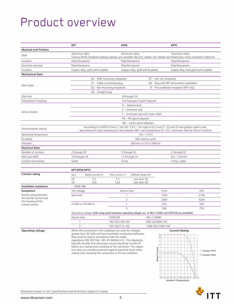
KPT /KPSE /KPTCContact rating Size Rated current A Test current A Millivolt drop mV
2016
7,513,0
7,513,0
Less than 55Less than 50
Insulation resistance ~ 5000 MΩ
Exceptions Test voltage Service class Vrms VDC
Service rating between the central contact and the housing of the coaxial contact
Seal Level 1 1500 2100
2 2300 3200
21336 m / 70 000 ft. 1 375 535
2 550 770
Operating voltage (with scoop proof connectors operating voltages acc. to MIL-C-26482 and VG95328 are permitted)
Service class VG95328 MIL-C-26482
1 140 VDC/100 VAC 850 VDC/600 VAC
2 165 VDC/115 VAC 1400 VDC/1000 VAC
Operating voltage When the connectors in this catalogue are used for voltages greater than 50 Volts and have touchable conductive shell parts they must be used in accordance with the safety regulations DIN VDE Part 140; IEC 60364-4-41. This regulation basically dictates that the power source should be turned off before any mating and unmating of the connector. This regula-tion does not provide protection against electrical shock when mating and unmating the connectors in the live condition.

www.ittcannon.com
Dimensions shown in mm | Specifications and dimensions subject to change
6
Product overview ................................................. 5
How to use this catalogue .................................... 7
Part number creation ........................................... 8
Ordering reference ...............................................10
Contact arrangements ..........................................12
Alternate insert positions ......................................15
Wall mounting receptacles ...................................16
Cable connecting plugs ........................................17
Box mounting receptacles ....................................18
Thru-bulkhead receptacles ....................................18
Straight plugs ......................................................19
Jam nut receptacles ..............................................21
Right angle plugs .................................................22
Special versions
Connectors with grounding continuity..................23
Receptacles with straight solder pins ....................26
Accessories and tooling
Panel cutouts .......................................................27
Protective caps .....................................................28
Dummy receptacle ...............................................30
Cross reference lists .............................................31
Tools and accessories ..........................................32
KPSE contact and sealing principle .......................33
Product safety information ...................................34
Table of contents
www.ittcannon.com
Dimensions shown in mm | Specifications and dimensions subject to change
7
Select your product using either the “part number creation” or “ordering reference” option
Use the detail pages to better understand the available options and choose the best solution for your needs
Add accessories and tooling as required on the related pages
Use the contact information on the back cover to contact us for further questions or to get advise on where you can purchase our products
1
2
3
4
How to useThis catalog is split in several sections that help you to
• get a general overview of all product lines (product overview)
• create a product part number step by step
(part number creation OR ordering reference)
• get all required detail information (dimensions, product details)
• get all required support products (accessories, tooling)
The fastest way to find your product of choice is to follow these steps

www.ittcannon.com
Dimensions shown in mm | Specifications and dimensions subject to change
8
Part number creation plugFollow these steps to design your connector part number.
Design your part number as per above steps
KPSE / KPTExamples
STEP 1 STEP 2 STEP 3 STEP 4 STEP 5 STEP 6Shell style Class / Backshell Contact arrangement Contact gender Insulation rotation Mod code (max. 3 codes)
Solder Industrial KPT6 E 20 – 41 P – DZ
Crimp Industrial KPSE6 E 14 – 12 S – W – F42 – A240 – F0
KPTCExamples
STEP 1 STEP 2 STEP 3 STEP 4 STEP 6 STEP 5 STEP 6Shell style Class / Backshell Contact arrangement Contact gender Plating Insulation rotation Mod code (max. 3 codes)
Solder Industrial KPTC6 E 20 – 41 P C – MA
Crimp Industrial KPTC6 PG 14 – 12 S – D W – P13,5 – MB
STEP 1 Select shell style (plug)
Shell Style Plug Shell Style Plug Shell Style Plug
Plug straight SolderKPT06KPTC6CrimpKPSE06
Plug straight shielded
SolderKPT6-DZKPTC6-DZCrimpKPSE6-DZ
Plug 90° Solder KPT08 KPTC8 Crimp KPSE08
STEP 2 Choose backshell
Class AGeneral duty with thread
Class F Grommet seal with strain relief
Class E add mod. code DN Environmental, grommet seal,heat shrink boot adapter
Class PG; ME KPTC onlyEnvironmental
Class E add Mod. code DZ Environmental, grommet seal, shielded heat shrink boot adapter
Class F, 90°Grommet seal with thread and cable clamp
Class A, 90° General duty with thread Class E, 90° Grommet seal with thread
STEP 3 Choose layout see page 12 –14 for layouts
STEP 4 Choose gender P=pin S=socket
STEP 5 Choose rotation see page 15 for rotation (omit for normal position)
STEP 6 Choose modification* see page 11 for modifications (omit if no modification is required)
* If a modification is used the initial ‚0‘ in the shell style description is omitted e.g. KPT01 is changed to KPT1. KPTC series does never use the initial ‚0‘ e.g. KPTC6

www.ittcannon.com
Dimensions shown in mm | Specifications and dimensions subject to change
9
Part number creation receptacle
Design your part number as per above steps
Follow these steps to design your connector part number.
KPSE / KPTExamples
STEP 1 STEP 2 STEP 3 STEP 4 STEP 5 STEP 6Shell style Class / Backshell Contact arrangement Contact gender Insulation rotation Mod code (max. 3 codes)
Solder Industrial KPT02 E 20 – 41 P
Crimp Industrial KPSE1 E 14 – 12 S – W – F42 – A240 – F0
KPTCExamples
STEP 1 STEP 2 STEP 3 STEP 4 STEP 6 STEP 5 STEP 6Shell style Class / Backshell Contact arrangement Contact gender Plating Insulation rotation Mod code (max. 3 codes)
Solder Industrial KPTC2 E 20 – 41 P C – MA
Crimp Industrial KPTC0 PG 14 – 12 S – D W – P13,5 – MB
STEP 1 Select shell style (receptacle)
Wall Mount Cable connecting Jam Nut* Box Mount* Thru-Bulkhead
SolderKPT00KPTC0
CrimpKPSE00KPTC0
SolderKPT01KPTC1
CrimpKPSE01
SolderKPT07KPTC7
CrimpKPSE07KPTC7
SolderKPT02KPTC2
CrimpKPSE02KPTC2
KPTB(contacts pre-installed)
STEP 2 Choose backshell
Class AGeneral duty with thread
Class F Grommet seal with strain relief
Class EEnvironmental, grommet seal,no clamp
Class E add Mod. code DNEnvironmental, grommet seal,heat shrink boot adapter
Class PG or MEEnvironmental, KPTC only
Class E add Mod. code DZEnvironmental, grommet sealshielded heat shrink boot adapter
STEP 3 Choose layout see page 12 –14 for layouts
STEP 4 Choose gender P=pin S=socket
STEP 5 Choose rotation see page 15 for rotation (omit for normal position)
STEP 6 Choose modification** see page 11 for modifications (omit if no modification is required)
* Shell style 02 (box mount) and 07A (jam nut) doesn‘t accept a backshell ** If a modification is used the initial ‚0‘ in the shell style description is omitted e.g. KPT01 is changed to KPT1. KPTC series does never use the initial ‚0‘ e.g. KPTC6

www.ittcannon.com
Dimensions shown in mm | Specifications and dimensions subject to change
10
Ordering reference
Series
KPSE – Cannon prefix crimp, contacts supplied
KPT – Cannon prefix solder, contacts installed
KPTC – Cannon prefix commercial version, contacts to be ordered separately
Shell type
Cannon designation omit 0 in case of a mod code and KPTC
00 – wall mounting receptacle see page 16
01 – cable connecting plug see page 17
02 – box mounting receptacle (class E only), thru-bulkhead recep. see page 18
06 – straight plug see page 19/20
07 – jam nut receptacle see page 21
08 – 90° angle plug see page 22
Class
A – general duty with thread
E – grommet seal, environmental, no clamp
E – grommet seal, in combination with modification DN or DZ
F – grommet seal with strain relief
PG – endbell for PG glands
ME – endbell for metric glands
Shell size
8 – 24
Contact arrangement see page 12–14
Contact type
P – pin
S – socket
Alternate insert position
W, X, Y and Z (omit for normal position) see page 15
Modification see page 11
KPT / KPSE / KPTC KP.. 22 – 36E P W *02
* If a modification is used the initial ‚0‘ in the shell style description is omitted e.g. KPT01 is changed to KPT1. KPTC series does never use the initial ‚0‘ e.g. KPTC6
www.ittcannon.com
Dimensions shown in mm | Specifications and dimensions subject to change
11
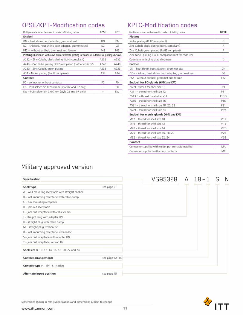
Specification
Shell type see page 31
A – wall mounting receptacle with straight endbell
B – wall mounting receptacle with cable clamp
C – box mounting receptacle
D – jam nut receptacle
E – jam nut receptacle with cable clamp
J – straight plug with adapter DN
K – straight plug with cable clamp
M – straight plug, version DZ
R – wall mounting receptacle, version DZ
S – jam nut receptacle with adapter DN
T – jam nut receptacle, version DZ
Shell size 8, 10, 12, 14, 16, 18, 20, 22 and 24
Contact arrangements see page 12 –14
Contact type P – pin S – socket
Alternate insert position see page 15
VG95328 18 – 1A S N
Multiple codes can be used in order of listing below KPSE KPT
Endbell
DN – heat shrink boot adapter, grommet seal DN DN
DZ – shielded, heat shrink boot adapter, grommet seal DZ DZ
F42 – without endbell, grommet and ferrule F42 F42
Plating (Cadmium with olive drab chromate plating is standard; Alternative platings below)
A232 – Zinc Cobalt, black plating (RoHS compliant) A232 A232
A240 – Zinc Nickel plating (RoHS compliant) (not for code DZ) A240 A240
A233 – Zinc Cobalt, green plating A233 A233
A34 – Nickel plating (RoHS compliant) A34 A34
Contact
F0 – connector without contacts F0 F0
EX – PCB solder pin 0,76x7mm (style 02 and 07 only) – EX
EW – PCB solder pin 0,6x7mm (style 02 and 07 only) – EW
Multiple codes can be used in order of listing below KPTC
Plating
Nickel plating (RoHS compliant) C
Zinc Cobalt black plating (RoHS compliant) R
Zinc Cobalt green plating (RoHS compliant) F
Zinc Nickel plating (RoHS compliant) (not for code DZ) H
Cadmium with olive drab chromate D
Endbell
DN – heat shrink boot adapter, grommet seal DN
DZ – shielded, heat shrink boot adapter, grommet seal DZ
F42 – without endbell, grommet and ferrule F42
Endbell for PG glands (KPTC and KPT)
PG09 - thread for shell size 10 P9
PG11 – thread for shell size 12 P11
PG13,5 – thread for shell size14 P13,5
PG16 – thread for shell size 16 P16
PG21 – thread for shell size 18, 20, 22 P21
PG29 – thread for shell size 24 P29
Endbell for metric glands (KPTC and KPT)
M12 – thread for shell size 10 M12
M16 – thread for shell size 12 M16
M20 – thread for shell size 14 M20
M25 – thread for shell size 16, 18, 20 M25
M32 – thread for shell size 22, 24 M32
Contact
Connector supplied with solder pot contacts installed MA
Connector supplied with crimp contacts MB
KPSE/KPT-Modification codes
Military approved version
KPTC-Modification codes
www.ittcannon.com
Dimensions shown in mm | Specifications and dimensions subject to change
12
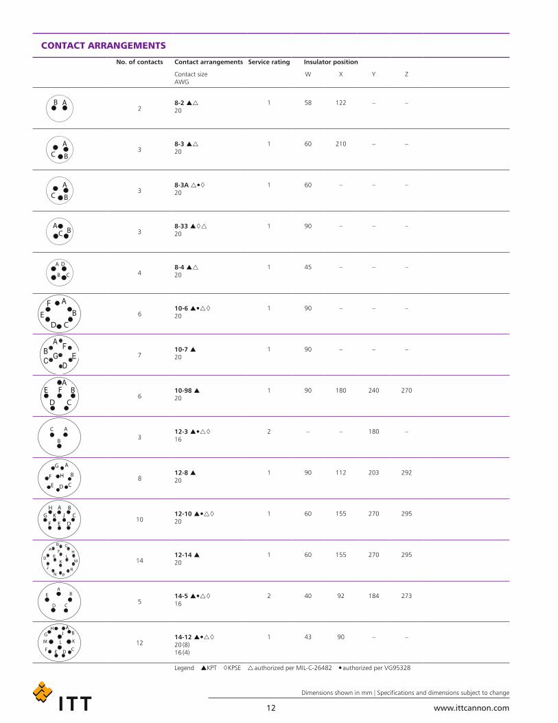
CONTACT ARRANGEMENTS
No. of contacts Contact arrangements Service rating Insulator position
Contact size AWG
W X Y Z
28-2 20
1 58 122 – –
38-3 20
1 60 210 – –
38-3A 20
1 60 – – –
38-33 20
1 90 – – –
48-4 20
1 45 – – –
610-6 20
1 90 – – –
710-7 20
1 90 – – –
610-98 20
1 90 180 240 270
312-3 16
2 – – 180 –
812-8 20
1 90 112 203 292
1012-10 20
1 60 155 270 295
1412-14 20
1 60 155 270 295
514-5 16
2 40 92 184 273
1214-12 20 (8) 16 (4)
1 43 90 – –
Legend KPT KPSE authorized per MIL-C-26482 authorized per VG95328
www.ittcannon.com
Dimensions shown in mm | Specifications and dimensions subject to change
13
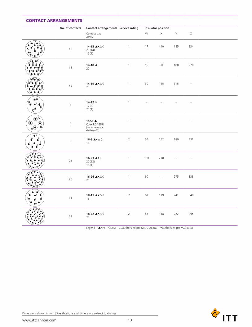
CONTACT ARRANGEMENTS
No. of contacts Contact arrangements Service rating Insulator position
Contact size AWG
W X Y Z
1514-15 20 (14) 16 (1)
1 17 110 155 234
1814-18 20
1 15 90 180 270
1914-19 20
1 30 165 315 –
514-22 12 (4) 20 (1)
1 – – – –
414A4 Coax RG 188 U (not for receptacle shell style 02)
1 – – – –
816-8 16
2 54 152 180 331
2316-23 20 (22) 16 (1)
1 158 270 – –
2616-26 20
1 60 – 275 338
1118-11 16
2 62 119 241 340
3218-32 20
2 85 138 222 265
Legend KPT KPSE authorized per MIL-C-26482 authorized per VG95328

www.ittcannon.com
Dimensions shown in mm | Specifications and dimensions subject to change
14
CONTACT ARRANGEMENTS
No. of contacts Contact arrangements Service rating Insulator position
Contact size AWG
W X Y Z
520A6 12 Note: contacts are 1 grounding pin and 4 standard size 12 pins
2 90 180 270 –
1620-16 16
2 238 316 333 347
2420-24 20
1 70 145 215 290
3920-39 20 (37) 16 (2)
1 63 114 252 333
4120-41 20
1 45 126 225 –
2122-21 16
2 16 135 175 349
3622-36 20
1 72 144 216 288
4122-41 20 (27) 16 (14)
1 2
39 135 264 –
5522-55 20
1 30 142 226 314
6124-61 20
1 90 180 270 324
Legend KPT KPSE authorized per MIL-C-26482 authorized per VG95328
www.ittcannon.com
Dimensions shown in mm | Specifications and dimensions subject to change
15
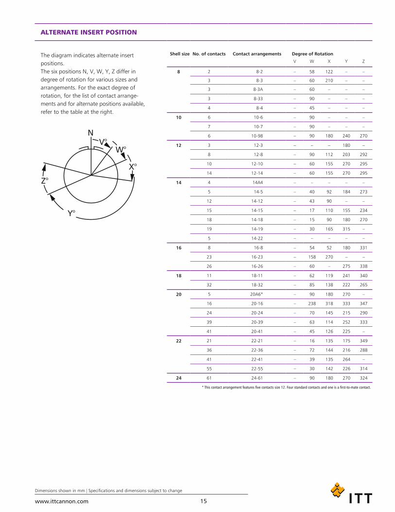
ALTERNATE INSERT POSITION
The diagram indicates alternate insert positions.The six positions N, V, W, Y, Z differ in degree of rotation for various sizes and arrangements. For the exact degree of rotation, for the list of contact arrange-ments and for alternate positions available, refer to the table at the right.
Shell size No. of contacts Contact arrangements Degree of Rotation
V W X Y Z
8 2 8-2 – 58 122 – –
3 8-3 – 60 210 – –
3 8-3A – 60 – – –
3 8-33 – 90 – – –
4 8-4 – 45 – – –
10 6 10-6 – 90 – – –
7 10-7 – 90 – – –
6 10-98 – 90 180 240 270
12 3 12-3 – – – 180 –
8 12-8 – 90 112 203 292
10 12-10 – 60 155 270 295
14 12-14 – 60 155 270 295
14 4 14A4 – – – – –
5 14-5 – 40 92 184 273
12 14-12 – 43 90 – –
15 14-15 – 17 110 155 234
18 14-18 – 15 90 180 270
19 14-19 – 30 165 315 –
5 14-22 – – – – –
16 8 16-8 – 54 52 180 331
23 16-23 – 158 270 – –
26 16-26 – 60 – 275 338
18 11 18-11 – 62 119 241 340
32 18-32 – 85 138 222 265
20 5 20A6* – 90 180 270 –
16 20-16 – 238 318 333 347
24 20-24 – 70 145 215 290
39 20-39 – 63 114 252 333
41 20-41 – 45 126 225 –
22 21 22-21 – 16 135 175 349
36 22-36 – 72 144 216 288
41 22-41 – 39 135 264 –
55 22-55 – 30 142 226 314
24 61 24-61 – 90 180 270 324
* This contact arrangement features five contacts size 12. Four standard contacts and one is a first-to-mate contact.
www.ittcannon.com
Dimensions shown in mm | Specifications and dimensions subject to change
16
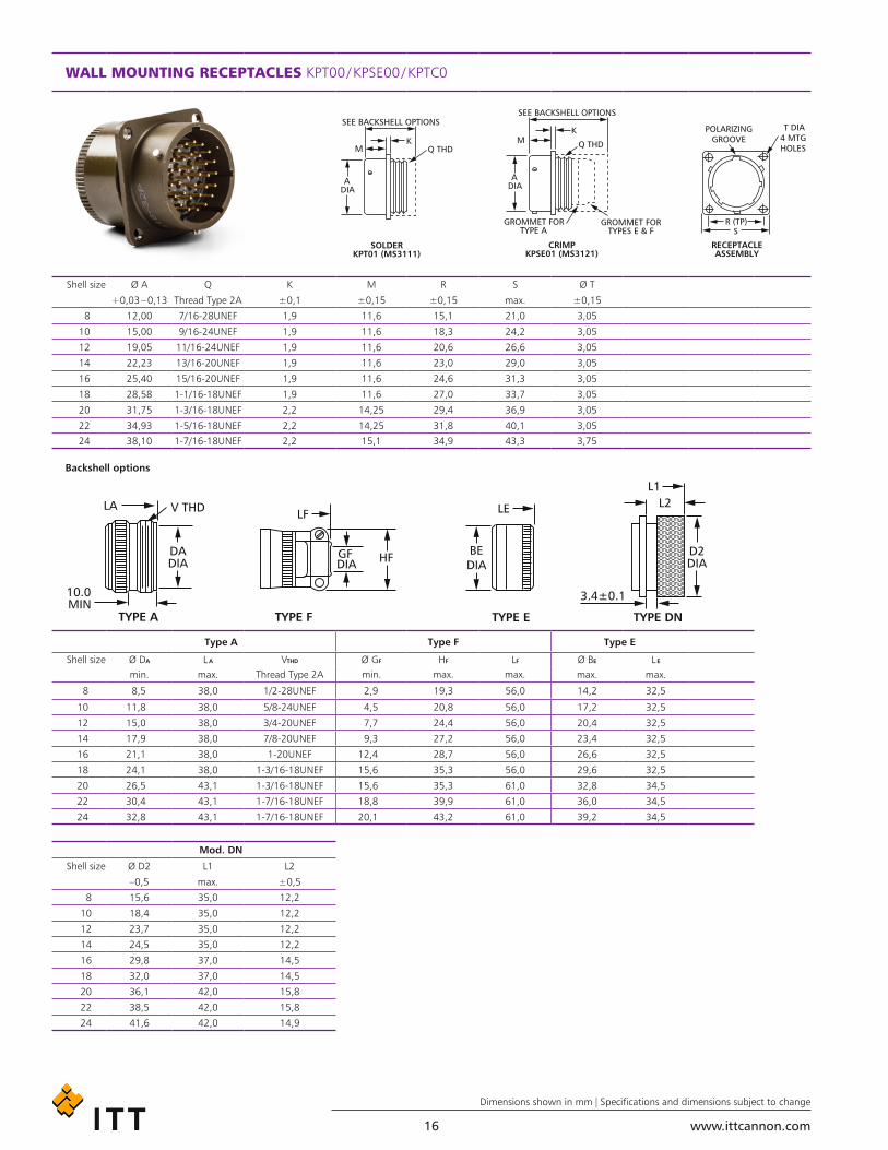
WALL MOUNTING RECEPTACLES KPT00 / KPSE00 / KPTC0
Shell size Ø A Q K M R S Ø T
+0,03 – 0,13 Thread Type 2A ±0,1 ±0,15 ±0,15 max. ±0,15
8 12,00 7/16-28UNEF 1,9 11,6 15,1 21,0 3,05
10 15,00 9/16-24UNEF 1,9 11,6 18,3 24,2 3,05
12 19,05 11/16-24UNEF 1,9 11,6 20,6 26,6 3,05
14 22,23 13/16-20UNEF 1,9 11,6 23,0 29,0 3,05
16 25,40 15/16-20UNEF 1,9 11,6 24,6 31,3 3,05
18 28,58 1-1/16-18UNEF 1,9 11,6 27,0 33,7 3,05
20 31,75 1-3/16-18UNEF 2,2 14,25 29,4 36,9 3,05
22 34,93 1-5/16-18UNEF 2,2 14,25 31,8 40,1 3,05
24 38,10 1-7/16-18UNEF 2,2 15,1 34,9 43,3 3,75
Backshell options
Type A Type F Type E
Shell size Ø DA L A VTHD Ø GF HF LF Ø BE L Emin. max. Thread Type 2A min. max. max. max. max.
8 8,5 38,0 1/2-28UNEF 2,9 19,3 56,0 14,2 32,5
10 11,8 38,0 5/8-24UNEF 4,5 20,8 56,0 17,2 32,5
12 15,0 38,0 3/4-20UNEF 7,7 24,4 56,0 20,4 32,5
14 17,9 38,0 7/8-20UNEF 9,3 27,2 56,0 23,4 32,5
16 21,1 38,0 1-20UNEF 12,4 28,7 56,0 26,6 32,5
18 24,1 38,0 1-3/16-18UNEF 15,6 35,3 56,0 29,6 32,5
20 26,5 43,1 1-3/16-18UNEF 15,6 35,3 61,0 32,8 34,5
22 30,4 43,1 1-7/16-18UNEF 18,8 39,9 61,0 36,0 34,5
24 32,8 43,1 1-7/16-18UNEF 20,1 43,2 61,0 39,2 34,5
Mod. DN
Shell size Ø D2 L1 L2
–0,5 max. ±0,5
8 15,6 35,0 12,2
10 18,4 35,0 12,2
12 23,7 35,0 12,2
14 24,5 35,0 12,2
16 29,8 37,0 14,5
18 32,0 37,0 14,5
20 36,1 42,0 15,8
22 38,5 42,0 15,8
24 41,6 42,0 14,9
www.ittcannon.com
Dimensions shown in mm | Specifications and dimensions subject to change
17
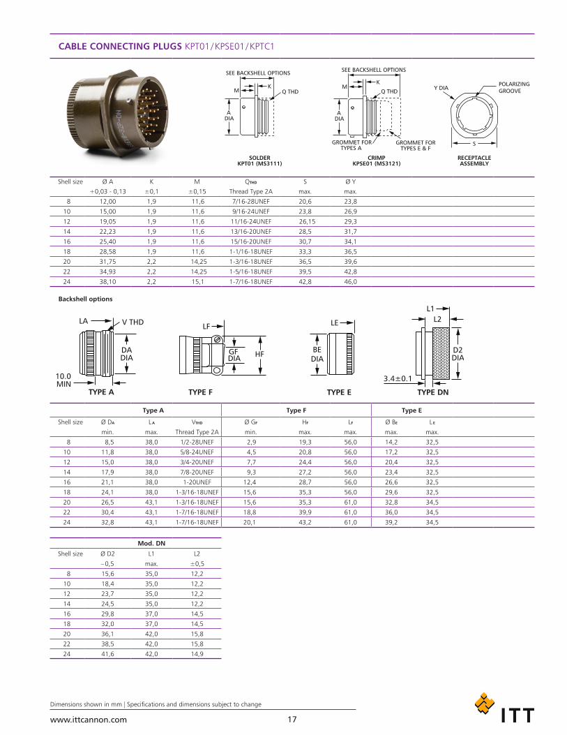
CABLE CONNECTING PLUGS KPT01 / KPSE01 / KPTC1
Shell size Ø A K M QTHD S Ø Y
+0,03 - 0,13 ±0,1 ±0,15 Thread Type 2A max. max.
8 12,00 1,9 11,6 7/16-28UNEF 20,6 23,8
10 15,00 1,9 11,6 9/16-24UNEF 23,8 26,9
12 19,05 1,9 11,6 11/16-24UNEF 26,15 29,3
14 22,23 1,9 11,6 13/16-20UNEF 28,5 31,7
16 25,40 1,9 11,6 15/16-20UNEF 30,7 34,1
18 28,58 1,9 11,6 1-1/16-18UNEF 33,3 36,5
20 31,75 2,2 14,25 1-3/16-18UNEF 36,5 39,6
22 34,93 2,2 14,25 1-5/16-18UNEF 39,5 42,8
24 38,10 2,2 15,1 1-7/16-18UNEF 42,8 46,0
Backshell options
Type A Type F Type E
Shell size Ø DA L A VTHD Ø GF HF LF Ø BE L E
min. max. Thread Type 2A min. max. max. max. max.
8 8,5 38,0 1/2-28UNEF 2,9 19,3 56,0 14,2 32,5
10 11,8 38,0 5/8-24UNEF 4,5 20,8 56,0 17,2 32,5
12 15,0 38,0 3/4-20UNEF 7,7 24,4 56,0 20,4 32,5
14 17,9 38,0 7/8-20UNEF 9,3 27,2 56,0 23,4 32,5
16 21,1 38,0 1-20UNEF 12,4 28,7 56,0 26,6 32,5
18 24,1 38,0 1-3/16-18UNEF 15,6 35,3 56,0 29,6 32,5
20 26,5 43,1 1-3/16-18UNEF 15,6 35,3 61,0 32,8 34,5
22 30,4 43,1 1-7/16-18UNEF 18,8 39,9 61,0 36,0 34,5
24 32,8 43,1 1-7/16-18UNEF 20,1 43,2 61,0 39,2 34,5
Mod. DN
Shell size Ø D2 L1 L2
– 0,5 max. ±0,5
8 15,6 35,0 12,2
10 18,4 35,0 12,2
12 23,7 35,0 12,2
14 24,5 35,0 12,2
16 29,8 37,0 14,5
18 32,0 37,0 14,5
20 36,1 42,0 15,8
22 38,5 42,0 15,8
24 41,6 42,0 14,9

www.ittcannon.com
Dimensions shown in mm | Specifications and dimensions subject to change
18
BOX MOUNTING RECEPTACLE KPT02 / KPSE02 / KPTC2
KPT / KPSE / KPTC KPT / KPTC
Shell size Ø A L Ø N K M R S Ø T Zmax.+0,03 – 0,13 max. max. ±0,1 ±0,15 ±0,15 max. ±0,15
8 12,00 21,1 11,1 1,9 11,6 15,1 21,0 3,05 12,3
10 15,00 21,1 14,3 1,9 11,6 18,3 24,2 3,05 12,3
12 19,05 21,1 17,5 1,9 11,6 20,6 26,6 3,05 12,3
14 22,23 21,1 20,6 1,9 11,6 23,0 29,0 3,05 12,3
16 25,40 21,1 23,8 1,9 11,6 24,6 31,3 3,05 12,3
18 28,58 21,1 27,0 1,9 11,6 27,0 33,7 3,05 12,3
20 31,75 22,7 30,2 2,2 14,25 29,4 36,9 3,05 10,8
22 34,93 22,7 33,4 2,2 14,25 31,8 40,1 3,05 10,8
24 38,10 22,7 36,5 2,2 15,1 34,9 43,3 3,75 10,0
THRU-BULKHEAD RECEPTACLES KPTB
Shell size Ø A K L M T R S Ø X
+0,03 – 0,13 ±0,1 max. ±0,25 max. ±0,15 max. ±0,15
8 12,00 1,8 28,6 14,5 6,0 15,1 21,0 3,05
10 15,00 1,8 28,6 14,5 6,0 18,3 24,2 3,05
12 19,05 1,8 28,6 14,5 6,0 20,6 26,6 3,05
14 22,23 1,8 28,6 14,5 6,0 23,0 29,0 3,05
16 25,40 1,8 28,6 14,5 6,0 24,6 31,3 3,05
18 28,58 1,8 28,6 14,5 6,0 27,0 33,7 3,05
20 31,75 2,5 31,9 17,7 9,2 29,4 36,9 3,05
22 34,93 2,5 31,9 17,7 9,2 31,8 40,1 3,05
24 38,10 2,5 31,9 17,7 8,0 34,9 43,3 3,75
www.ittcannon.com
Dimensions shown in mm | Specifications and dimensions subject to change
19
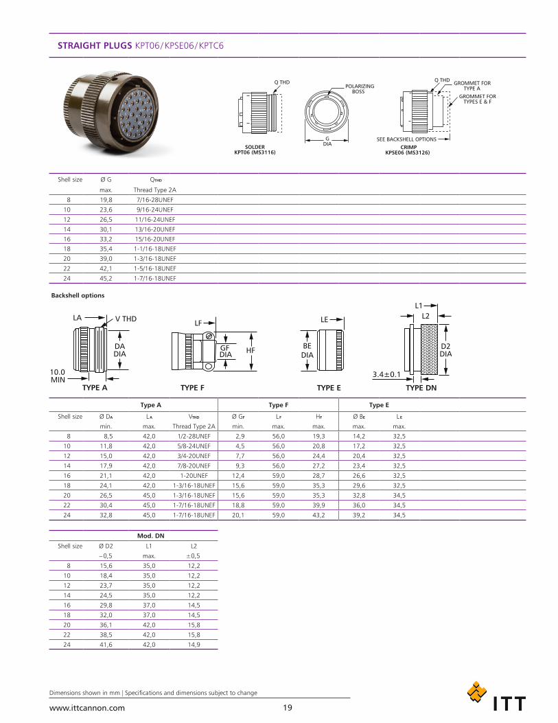
STRAIGHT PLUGS KPT06 / KPSE06 / KPTC6
Shell size Ø G QTHD
max. Thread Type 2A
8 19,8 7/16-28UNEF
10 23,6 9/16-24UNEF
12 26,5 11/16-24UNEF
14 30,1 13/16-20UNEF
16 33,2 15/16-20UNEF
18 35,4 1-1/16-18UNEF
20 39,0 1-3/16-18UNEF
22 42,1 1-5/16-18UNEF
24 45,2 1-7/16-18UNEF
Backshell options
Type A Type F Type E
Shell size Ø DA L A VTHD Ø GF L F HF Ø BE L E
min. max. Thread Type 2A min. max. max. max. max.
8 8,5 42,0 1/2-28UNEF 2,9 56,0 19,3 14,2 32,5
10 11,8 42,0 5/8-24UNEF 4,5 56,0 20,8 17,2 32,5
12 15,0 42,0 3/4-20UNEF 7,7 56,0 24,4 20,4 32,5
14 17,9 42,0 7/8-20UNEF 9,3 56,0 27,2 23,4 32,5
16 21,1 42,0 1-20UNEF 12,4 59,0 28,7 26,6 32,5
18 24,1 42,0 1-3/16-18UNEF 15,6 59,0 35,3 29,6 32,5
20 26,5 45,0 1-3/16-18UNEF 15,6 59,0 35,3 32,8 34,5
22 30,4 45,0 1-7/16-18UNEF 18,8 59,0 39,9 36,0 34,5
24 32,8 45,0 1-7/16-18UNEF 20,1 59,0 43,2 39,2 34,5
Mod. DN
Shell size Ø D2 L1 L2
– 0,5 max. ±0,5
8 15,6 35,0 12,2
10 18,4 35,0 12,2
12 23,7 35,0 12,2
14 24,5 35,0 12,2
16 29,8 37,0 14,5
18 32,0 37,0 14,5
20 36,1 42,0 15,8
22 38,5 42,0 15,8
24 41,6 42,0 14,9

www.ittcannon.com
Dimensions shown in mm | Specifications and dimensions subject to change
20
STRAIGHT PLUG KPT6PG / KPTC6PG
Shell size Ø G Ø B C LPG PGTHD
max. max. min. max.
10 23,6 19,0 10,5 58,5 PG 09
12 26,5 22,5 10,5 58,5 PG 11
14 30,1 25,0 10,5 58,5 PG 13,5
16 33,2 28,0 10,5 73,0 PG 16
18 35,4 32,5 11,5 73,0 PG 21
20 39,0 34,5 11,5 76,0 PG 21
22 42,1 38,0 11,5 82,0 PG 21
24 45,2 40,5 11,5 82,0 PG 29
STRAIGHT PLUG KPT6ME / KPTC6ME
Shell size Ø G Ø B C LME Metric Thread
max. max. min. max.
10 23,6 19,0 10,5 58,5 M 12 x 1,5
12 26,5 22,5 10,5 58,5 M 16 x 1,5
14 30,1 25,0 10,5 58,5 M 20 x 1,5
16 33,2 28,0 10,5 73,0 M 25 x 1,5
18 35,4 32,5 11,5 73,0 M 25 x 1,5
20 39,0 34,5 11,5 76,0 M 25 x 1,5
22 42,1 38,0 11,5 82,0 M 32 x 1,5
24 45,2 40,5 11,5 82,0 M 32 x 1,5
www.ittcannon.com
Dimensions shown in mm | Specifications and dimensions subject to change
21
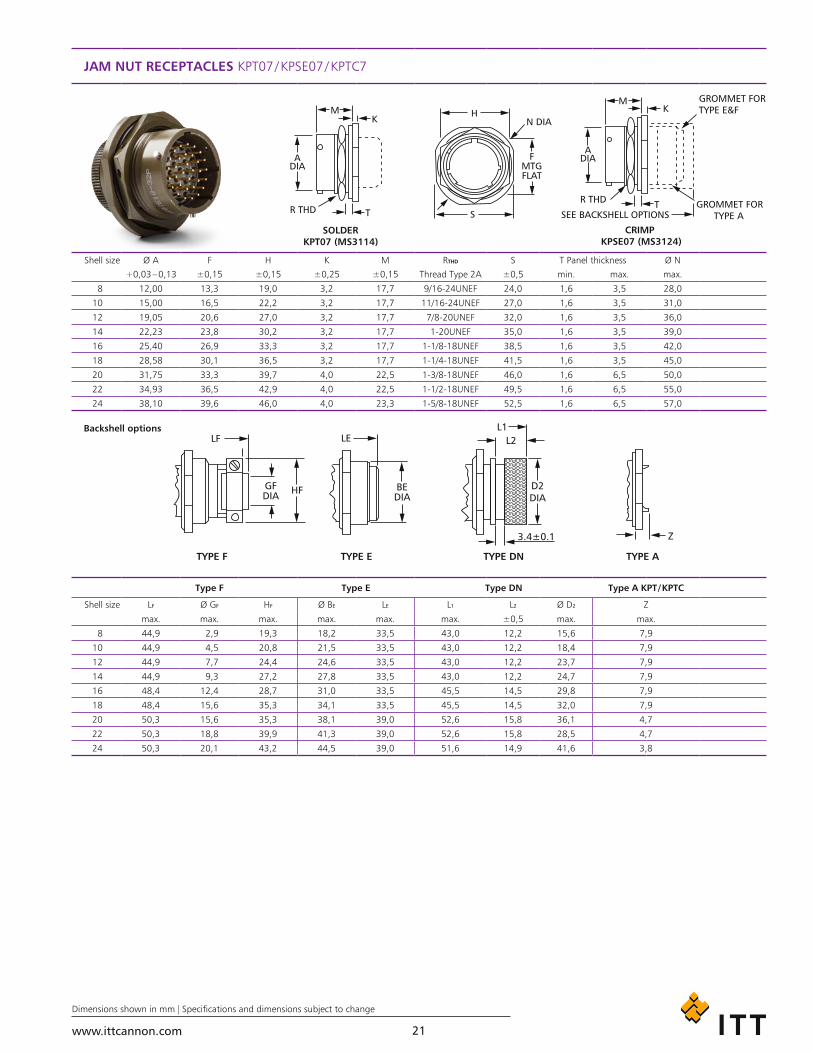
JAM NUT RECEPTACLES KPT07 / KPSE07 / KPTC7
Shell size Ø A F H K M RTHD S T Panel thickness Ø N
+0,03 – 0,13 ±0,15 ±0,15 ±0,25 ±0,15 Thread Type 2A ±0,5 min. max. max.
8 12,00 13,3 19,0 3,2 17,7 9/16-24UNEF 24,0 1,6 3,5 28,0
10 15,00 16,5 22,2 3,2 17,7 11/16-24UNEF 27,0 1,6 3,5 31,0
12 19,05 20,6 27,0 3,2 17,7 7/8-20UNEF 32,0 1,6 3,5 36,0
14 22,23 23,8 30,2 3,2 17,7 1-20UNEF 35,0 1,6 3,5 39,0
16 25,40 26,9 33,3 3,2 17,7 1-1/8-18UNEF 38,5 1,6 3,5 42,0
18 28,58 30,1 36,5 3,2 17,7 1-1/4-18UNEF 41,5 1,6 3,5 45,0
20 31,75 33,3 39,7 4,0 22,5 1-3/8-18UNEF 46,0 1,6 6,5 50,0
22 34,93 36,5 42,9 4,0 22,5 1-1/2-18UNEF 49,5 1,6 6,5 55,0
24 38,10 39,6 46,0 4,0 23,3 1-5/8-18UNEF 52,5 1,6 6,5 57,0
Backshell options
Type F Type E Type DN Type A KPT / KPTC
Shell size LF Ø GF HF Ø BE LE L1 L2 Ø D2 Z
max. max. max. max. max. max. ±0,5 max. max.
8 44,9 2,9 19,3 18,2 33,5 43,0 12,2 15,6 7,9
10 44,9 4,5 20,8 21,5 33,5 43,0 12,2 18,4 7,9
12 44,9 7,7 24,4 24,6 33,5 43,0 12,2 23,7 7,9
14 44,9 9,3 27,2 27,8 33,5 43,0 12,2 24,7 7,9
16 48,4 12,4 28,7 31,0 33,5 45,5 14,5 29,8 7,9
18 48,4 15,6 35,3 34,1 33,5 45,5 14,5 32,0 7,9
20 50,3 15,6 35,3 38,1 39,0 52,6 15,8 36,1 4,7
22 50,3 18,8 39,9 41,3 39,0 52,6 15,8 28,5 4,7
24 50,3 20,1 43,2 44,5 39,0 51,6 14,9 41,6 3,8

www.ittcannon.com
Dimensions shown in mm | Specifications and dimensions subject to change
22
RIGHT ANGLE PLUG, 90° KPT08 / KPSE08 / KPTC8
Shell size Ø G Q
max. Thread Type 2A
8 19,8 7/16-28UNEF
10 23,6 9/16-24UNEF
12 26,5 11/16-24UNEF
14 30,1 13/16-20UNEF
16 33,2 15/16-20UNEF
18 35,4 1-1/16-18UNEF
20 39,0 1-3/16-18UNEF
22 42,1 1-5/16-18UNEF
24 45,2 1-7/16-18UNEF
Backshell options
Type A and E Type F
Shell size LAE DAE VTHD L DF LF
max. max. Thread Type 2A max. max. max.
8 36,1 20,9 1/2-28UNEF 47,0 31,4 36,1
10 38,3 21,7 5/8-24UNEF 49,5 32,2 38,3
12 40,9 23,3 3/4-20UNEF 53,5 35,4 40,9
14 41,6 24,9 7/8-20UNEF 55,5 38,6 41,6
16 42,5 26,5 1-20UNEF 57,0 40,2 42,5
18 44,7 28,1 1-3/16-18UNEF 62,5 41,8 44,7
20 48,3 29,6 1-3/16-18UNEF 67,0 43,4 48,3
22 52,1 31,7 1-7/16-18UNEF 71,5 47,9 52,1
24 52,1 33,6 1-7/16-18UNEF 74,0 49,9 52,1
www.ittcannon.com
Dimensions shown in mm | Specifications and dimensions subject to change
23
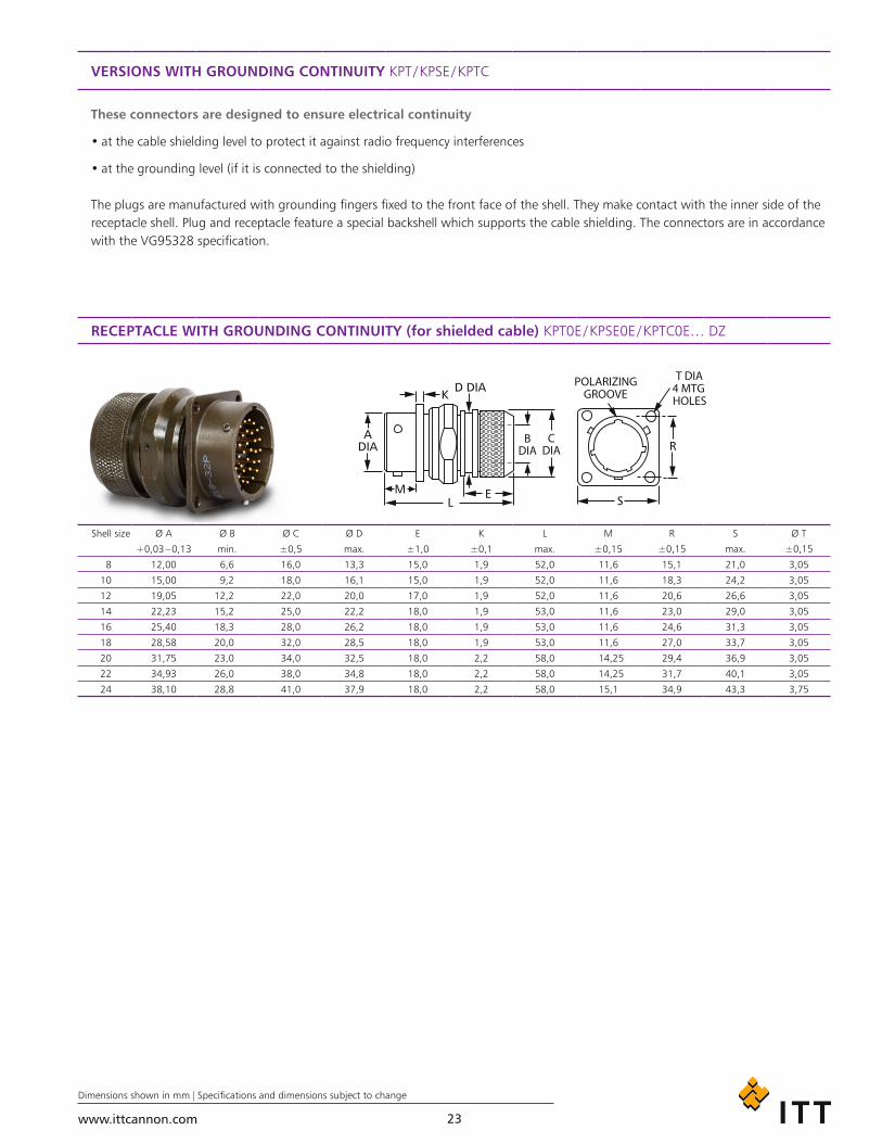
VERSIONS WITH GROUNDING CONTINUITY KPT / KPSE / KPTC
These connectors are designed to ensure electrical continuity
• at the cable shielding level to protect it against radio frequency interferences
• at the grounding level (if it is connected to the shielding)
The plugs are manufactured with grounding fingers fixed to the front face of the shell. They make contact with the inner side of the receptacle shell. Plug and receptacle feature a special backshell which supports the cable shielding. The connectors are in accordance with the VG95328 specification.
RECEPTACLE WITH GROUNDING CONTINUITY (for shielded cable) KPT0E / KPSE0E / KPTC0E… DZ
Shell size Ø A Ø B Ø C Ø D E K L M R S Ø T
+0,03 – 0,13 min. ±0,5 max. ±1,0 ±0,1 max. ±0,15 ±0,15 max. ±0,15
8 12,00 6,6 16,0 13,3 15,0 1,9 52,0 11,6 15,1 21,0 3,05
10 15,00 9,2 18,0 16,1 15,0 1,9 52,0 11,6 18,3 24,2 3,05
12 19,05 12,2 22,0 20,0 17,0 1,9 52,0 11,6 20,6 26,6 3,05
14 22,23 15,2 25,0 22,2 18,0 1,9 53,0 11,6 23,0 29,0 3,05
16 25,40 18,3 28,0 26,2 18,0 1,9 53,0 11,6 24,6 31,3 3,05
18 28,58 20,0 32,0 28,5 18,0 1,9 53,0 11,6 27,0 33,7 3,05
20 31,75 23,0 34,0 32,5 18,0 2,2 58,0 14,25 29,4 36,9 3,05
22 34,93 26,0 38,0 34,8 18,0 2,2 58,0 14,25 31,7 40,1 3,05
24 38,10 28,8 41,0 37,9 18,0 2,2 58,0 15,1 34,9 43,3 3,75
www.ittcannon.com
Dimensions shown in mm | Specifications and dimensions subject to change
24
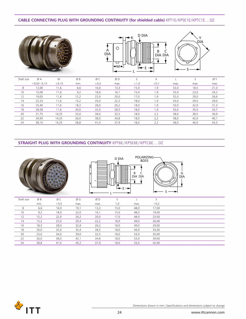
CABLE CONNECTING PLUG WITH GROUNDING CONTINUITY (for shielded cable) KPT1E / KPSE1E / KPTC1E … DZ
Shell size Ø A M Ø B Ø C Ø D E K L S Ø Y
+0,03 – 0,13 ±0,15 min. ±0,5 max. ±1,0 ±0,1 max. max. max.
8 12,00 11,6 6,6 16,0 13,3 15,0 1,9 52,0 18,5 21,0
10 15,00 11,6 9,2 18,0 16,1 15,0 1,9 52,0 23,0 24,2
12 19,05 11,6 12,2 22,0 20,0 17,0 1,9 52,0 29,0 26,6
14 22,23 11,6 15,2 25,0 22,2 18,0 1,9 53,0 29,5 29,0
16 25,40 11,6 18,3 28,0 26,2 18,0 1,9 53,0 32,0 31,3
18 28,58 11,6 20,0 32,0 28,5 18,0 1,9 53,0 35,0 33,7
20 31,75 14,25 23,0 34,0 32,5 18,0 2,2 58,0 38,5 36,9
22 34,93 14,25 26,0 38,0 34,8 18,0 2,2 58,0 42,0 40,1
24 38,10 14,25 28,8 41,0 37,9 18,0 2,2 58,0 46,0 43,3
STRAIGHT PLUG WITH GROUNDING CONTINUITY KPT6E / KPSE6E / KPTC6E … DZ
Shell size Ø B Ø C Ø G Ø D E L S
min. +0,5 max. max. 1,0 max. +0,2
8 6,6 16,0 19,1 13,3 15,0 48,0 17,00
10 9,2 18,0 22,0 16,1 15,0 48,0 19,00
12 12,2 22,0 26,2 20,0 17,0 48,0 23,00
14 15,2 25,0 29,4 22,2 18,0 49,0 26,00
16 18,3 28,0 32,8 26,2 18,0 49,0 29,00
18 20,0 32,0 35,4 28,5 18,0 49,0 33,00
20 23,0 34,0 39,0 32,5 18,0 53,0 35,00
22 26,0 38,0 42,1 34,8 18,0 53,0 39,00
24 28,8 41,0 45,2 37,9 18,0 53,0 42,00

www.ittcannon.com
Dimensions shown in mm | Specifications and dimensions subject to change
25
JAM NUT RECEPTACLE WITH GROUNDING CONTINUITY (for shielded cable) KPT 7E / KPSE 7E / KPTC … DZ
Shell size Ø A Ø B Ø C Ø D E L S T
min. +0,5 max. max. ±1,0 max. ±0,25 ±0,25
8 6,6 16,0 18,2 13,3 15,0 47,0 23,0 19,0
10 9,2 18,0 21,4 16,1 15,0 47,0 27,0 22,2
12 12,2 22,0 24,6 20,0 17,0 49,0 31,7 27,0
14 15,2 25,0 27,8 22,2 18,0 50,0 34,9 30,2
16 18,3 28,0 30,9 26,2 18,0 50,0 38,1 33,3
18 20,0 32,0 34,1 28,5 18,0 50,0 41,3 36,5
20 23,0 34,0 38,1 32,5 18,0 55,0 46,0 39,7
22 26,0 38,0 41,3 34,8 18,0 55,0 49,2 42,9
24 28,8 41,0 44,4 37,9 18,0 55,0 52,3 46,0
ASSEMBLY OF A CONNECTOR WITH A GROUND CONTINUITY BACKSHELL KPT / KPSE / KPTC … DZ
Shell size ØC
max.
8 6,6
10 9,2
12 12,2
14 15,2
16 18,3
18 20,0
20 23,0
22 26,0
24 28,8

www.ittcannon.com
Dimensions shown in mm | Specifications and dimensions subject to change
26
BOX MOUNTING RECEPTACLE KPT2 / KPTC2 … EX OR EW
Shell size Ø A K L M Ø N R S Ø T
+0,03 – 0,13 ±0,1 max. ±0,15 max. ±0,15 max. ±0,15
8 12,00 1,9 21,1 11,60 11,1 15,1 21,0 3,05
10 15,00 1,9 21,1 11,60 14,3 18,3 24,2 3,05
12 19,05 1,9 21,1 11,60 17,5 20,6 26,6 3,05
14 22,23 1,9 21,1 11,60 20,6 23,0 29,0 3,05
16 25,40 1,9 21,1 11,60 23,8 24,6 31,3 3,05
18 28,58 1,9 21,1 11,60 27,0 27,0 33,7 3,05
20 31,75 2,2 22,7 14,25 30,2 29,4 36,9 3,05
22 34,93 2,2 22,7 14,25 33,4 31,7 40,1 3,05
24 38,10 2,2 22,7 15,10 36,5 34,9 43,3 3,75
JAM NUT RECEPTACLES KPT7 / KPTC7 … EX OR EW
Shell size Ø A F H K M RTHD S T (Panel Thickness) Ø N
+0,03 – 0,13 ±0,15 ±0,15 ±0,25 ±0,15 Thread Type 2A ±0,5 min. max. max.
8 12,0 13,3 19,0 3,2 17,7 9/16-24UNEF 24,0 1,6 3,5 28,0
10 15,0 16,5 22,2 3,2 17,7 11/16-24UNEF 27,0 1,6 3,5 31,0
12 19,1 20,6 27,0 3,2 17,7 7/8-20UNEF 32,0 1,6 3,5 36,0
14 22,2 23,8 30,2 3,2 17,7 1-20UNEF 35,0 1,6 3,5 39,0
16 25,4 26,9 33,3 3,2 17,7 1-1/8-18UNEF 38,5 1,6 3,5 42,0
18 28,6 30,1 36,5 3,2 17,7 1-1/4-18UNEF 41,5 1,6 3,5 45,0
20 31,8 33,3 39,7 4,0 22,5 1-3/8-18UNEF 46,0 1,6 6,5 50,0
22 34,9 36,5 42,9 4,0 22,5 1-1/2-18UNEF 49,5 1,6 6,5 55,0
24 38,1 39,6 46,0 4,0 23,3 1-5/8-18UNEF 52,5 1,6 6,5 57,0

www.ittcannon.com
Dimensions shown in mm | Specifications and dimensions subject to change
27
PANEL CUTOUTS KPT / KPSE / KPTC
BOX MOUNTING RECEPTACLE
Shell size For rear mounting For front mounting
Ø D +0,25 / 0 Ø D +0,25 / 0 R ±0,15 Ø T +0,3
8 14,0 12,7 15,1 3,1
10 17,0 16,0 18,3 3,1
12 22,0 19,0 20,6 3,1
14 25,0 22,2 23,0 3,1
16 28,0 25,5 24,6 3,1
18 31,0 28,5 27,0 3,1
20 34,5 31,7 29,4 3,1
22 37,5 35,0 31,8 3,1
24 41,0 38,0 34,9 3,6
PANEL THICKNESSShell size P – Panel thickness
Height of screw head included
8 2,2
10 2,2
12 2,2
14 2,2
16 2,2
18 2,2
20 5,4
22 5,4
24 5,4
JAM NUT RECEPTACLE Shell size KPT / KPSE KPT / KPSE
Ø A +0,25 / –0 B +0 / –0,12
8 14,5 13,6
10 17,7 16,8
12 22,7 20,9
14 25,7 24,1
16 28,8 27,2
18 32,0 30,4
20 35,1 33,6
22 38,4 36,8
24 41,5 40,0
www.ittcannon.com
Dimensions shown in mm | Specifications and dimensions subject to change
28
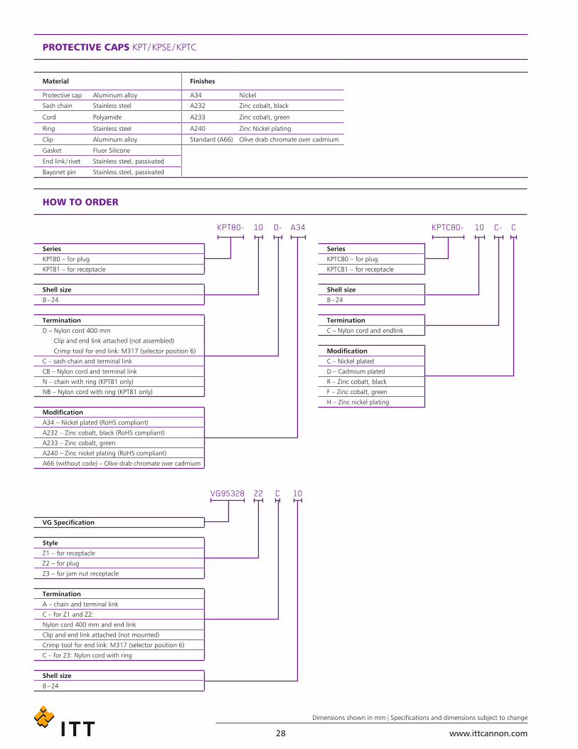
PROTECTIVE CAPS KPT / KPSE / KPTC
Material Finishes
Protective cap Aluminum alloy A34 Nickel
Sash chain Stainless steel A232 Zinc cobalt, black
Cord Polyamide A233 Zinc cobalt, green
Ring Stainless steel A240 Zinc Nickel plating
Clip Aluminum alloy Standard (A66) Olive drab chromate over cadmium
Gasket Fluor Silicone
End link / rivet Stainless steel, passivated
Bayonet pin Stainless steel, passivated
Series
KPT80 – for plug
KPT81 – for receptacle
Shell size
8 – 24
Termination
D – Nylon cord 400 mm
Clip and end link attached (not assembled)
Crimp tool for end link: M317 (selector position 6)
C – sash chain and terminal link
CB – Nylon cord and terminal link
N – chain with ring (KPT81 only)
NB – Nylon cord with ring (KPT81 only)
Modification
A34 – Nickel plated (RoHS compliant)
A232 – Zinc cobalt, black (RoHS compliant)
A233 – Zinc cobalt, green
A240 – Zinc nickel plating (RoHS compliant)
A66 (without code) – Olive drab chromate over cadmium
Series
KPTC80 – for plug
KPTC81 – for receptacle
Shell size
8 – 24
Termination
C – Nylon cord and endlink
Modification
C – Nickel plated
D – Cadmium plated
R – Zinc cobalt, black
F – Zinc cobalt, green
H – Zinc nickel plating
VG Specification
Style
Z1 – for receptacle
Z2 – for plug
Z3 – for jam nut receptacle
Termination
A – chain and terminal link
C – for Z1 and Z2:
Nylon cord 400 mm and end link
Clip and end link attached (not mounted)
Crimp tool for end link: M317 (selector position 6)
C – for Z3: Nylon cord with ring
Shell size
8 – 24
KPT80- KPTC80-
VG95328
A34 C
10
D- C-
C
10 10
Z2
HOW TO ORDER
www.ittcannon.com
Dimensions shown in mm | Specifications and dimensions subject to change
29
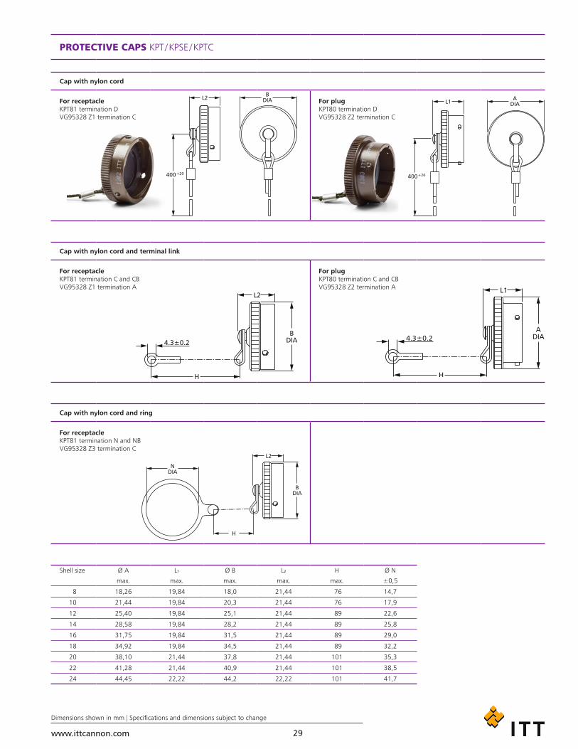
PROTECTIVE CAPS KPT / KPSE / KPTC
Cap with nylon cord
For receptacleKPT81 termination DVG95328 Z1 termination C
For plugKPT80 termination DVG95328 Z2 termination C
Cap with nylon cord and terminal link
For receptacleKPT81 termination C and CBVG95328 Z1 termination A
For plugKPT80 termination C and CBVG95328 Z2 termination A
Cap with nylon cord and ring
For receptacleKPT81 termination N and NBVG95328 Z3 termination C
Shell size Ø A L1 Ø B L2 H Ø N
max. max. max. max. max. ±0,5
8 18,26 19,84 18,0 21,44 76 14,7
10 21,44 19,84 20,3 21,44 76 17,9
12 25,40 19,84 25,1 21,44 89 22,6
14 28,58 19,84 28,2 21,44 89 25,8
16 31,75 19,84 31,5 21,44 89 29,0
18 34,92 19,84 34,5 21,44 89 32,2
20 38,10 21,44 37,8 21,44 101 35,3
22 41,28 21,44 40,9 21,44 101 38,5
24 44,45 22,22 44,2 22,22 101 41,7

www.ittcannon.com
Dimensions shown in mm | Specifications and dimensions subject to change
30
DUMMY RECEPTACLES KPT/KPSE/KPTC
HOW TO ORDER
Series
Dummy receptacle
Shell size
Flange
A – Standard
MSKPT
AA
88
3115-15-
Shell size Ø A K M R S Ø T
+0,03 – 0,13 ±0,4 ±0,15 ±0,15 max. ±0,15
* 8 A 12,00 1,6 12,1 15,1 21,0 3,05
* 10 A 15,00 1,6 12,1 18,3 24,2 3,05
* 12 A 19,05 1,6 12,1 20,6 26,6 3,05
* 14 A 22,23 1,6 12,1 23,0 29,0 3,05
* 16 A 25,40 1,6 12,1 24,6 31,3 3,05
* 18 A 28,58 1,6 12,1 27,0 33,7 3,05
* 20 A 31,75 2,4 14,5 29,4 36,9 3,05
* 22 A 34,93 2,4 14,5 31,8 40,1 3,05
* 24 A 38,10 2,4 15,4 34,9 43,3 3,75
* Add “KPT 15 -” or “MS 3115-” prefixes
www.ittcannon.com
Dimensions shown in mm | Specifications and dimensions subject to change
31
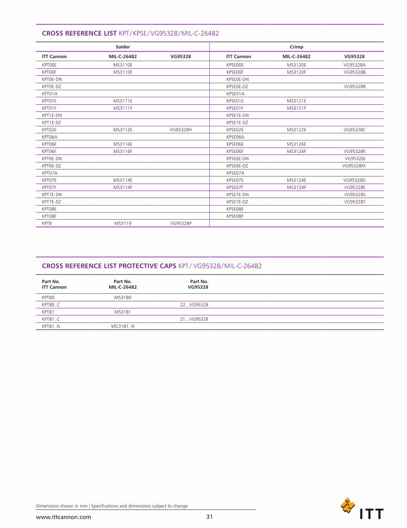
CROSS REFERENCE LIST KPT / KPSE / VG95328 / MIL-C-26482
Solder Crimp
ITT Cannon MIL-C-26482 VG95328 ITT Cannon MIL-C-26482 VG95328
KPT00E MS3110E KPSE00E MS3120E VG95328A
KPT00F MS3110F KPSE00F MS3120F VG95328B
KPT0E-DN KPSE0E-DN
KPT0E-DZ KPSE0E-DZ VG95328R
KPT01A KPSE01A
KPT01E MS3111E KPSE01E MS3121E
KPT01F MS3111F KPSE01F MS3121F
KPT1E-DN KPSE1E-DN
KPT1E-DZ KPSE1E-DZ
KPT02E MS3112E VG95328H KPSE02E MS3122E VG95328C
KPT06A KPSE06A
KPT06E MS3116E KPSE06E MS3126E
KPT06F MS3116F KPSE06F MS3126F VG95328K
KPT6E-DN KPSE6E-DN VG95328J
KPT6E-DZ KPSE6E-DZ VG95328M
KPT07A KPSE07A
KPT07E MS3114E KPSE07E MS3124E VG95328D
KPT07F MS3114F KPSE07F MS3124F VG95328E
KPT7E-DN KPSE7E-DN VG95328S
KPT7E-DZ KPSE7E-DZ VG95328T
KPT08E KPSE08E
KPT08F KPSE08F
KPTB MS3119 VG95328P
CROSS REFERENCE LIST PROTECTIVE CAPS KPT / VG95328 / MIL-C-26482
Part No. ITT Cannon
Part No. MIL-C-26482
Part No. VG95328
KPT80 MS3180
KPT80..C Z2...VG95328
KPT81 MS3181
KPT81..C Z1...VG95328
KPT81..N MS 3181..N
www.ittcannon.com
Dimensions shown in mm | Specifications and dimensions subject to change
32
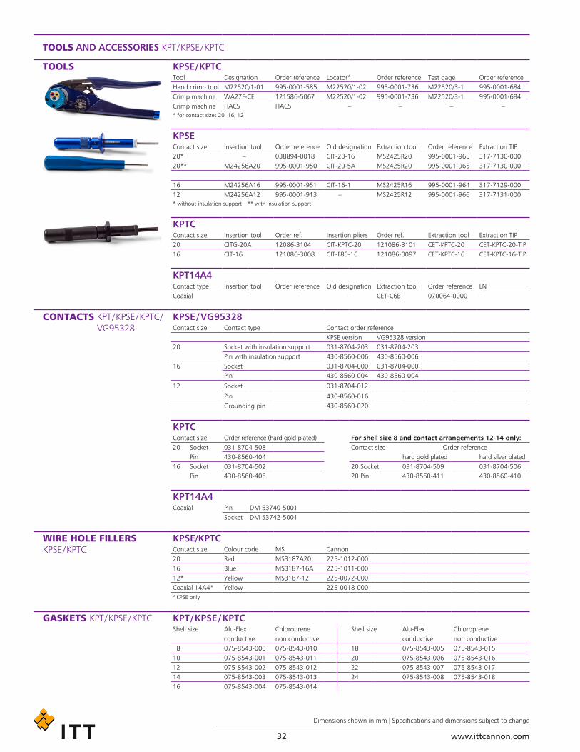
TOOLS AND ACCESSORIES KPT / KPSE / KPTC
TOOLS KPSE / KPTCTool Designation Order reference Locator* Order reference Test gage Order referenceHand crimp tool M22520/1-01 995-0001-585 M22520/1-02 995-0001-736 M22520/3-1 995-0001-684Crimp machine WA27F-CE 121586-5067 M22520/1-02 995-0001-736 M22520/3-1 995-0001-684Crimp machine HACS HACS – – – –* for contact sizes 20, 16, 12
KPSEContact size Insertion tool Order reference Old designation Extraction tool Order reference Extraction TIP20* – 038894-0018 CIT-20-16 MS2425R20 995-0001-965 317-7130-00020** M24256A20 995-0001-950 CIT-20-5A MS2425R20 995-0001-965 317-7130-000
16 M24256A16 995-0001-951 CIT-16-1 MS2425R16 995-0001-964 317-7129-00012 M24256A12 995-0001-913 – MS2425R12 995-0001-966 317-7131-000* without insulation support ** with insulation support
KPTCContact size Insertion tool Order ref. Insertion pliers Order ref. Extraction tool Extraction TIP20 CITG-20A 12086-3104 CIT-KPTC-20 121086-3101 CET-KPTC-20 CET-KPTC-20-TIP16 CIT-16 121086-3008 CIT-F80-16 121086-0097 CET-KPTC-16 CET-KPTC-16-TIP
KPT14A4Contact type Insertion tool Order reference Old designation Extraction tool Order reference LNCoaxial – – – CET-C6B 070064-0000 –
CONTACTS KPT / KPSE / KPTC / VG95328
KPSE / VG95328Contact size Contact type Contact order reference
KPSE version VG95328 version20 Socket with insulation support 031-8704-203 031-8704-203
Pin with insulation support 430-8560-006 430-8560-00616 Socket 031-8704-000 031-8704-000
Pin 430-8560-004 430-8560-004
12 Socket 031-8704-012
Pin 430-8560-016Grounding pin 430-8560-020
KPTC
Contact size Order reference (hard gold plated) For shell size 8 and contact arrangements 12-14 only:20 Socket 031-8704-508 Contact size Order reference Pin 430-8560-404 hard gold plated hard silver plated16 Socket 031-8704-502 20 Socket 031-8704-509 031-8704-506 Pin 430-8560-406 20 Pin 430-8560-411 430-8560-410
KPT14A4Coaxial Pin DM 53740-5001
Socket DM 53742-5001
WIRE HOLE FILLERS KPSE / KPTC
KPSE/KPTCContact size Colour code MS Cannon20 Red MS3187A20 225-1012-00016 Blue MS3187-16A 225-1011-00012* Yellow MS3187-12 225-0072-000Coaxial 14A4* Yellow – 225-0018-000* KPSE only
GASKETS KPT / KPSE / KPTC KPT / KPSE / KPTCShell size Alu-Flex Chloroprene Shell size Alu-Flex Chloroprene
conductive non conductive conductive non conductive 8 075-8543-000 075-8543-010 18 075-8543-005 075-8543-01510 075-8543-001 075-8543-011 20 075-8543-006 075-8543-01612 075-8543-002 075-8543-012 22 075-8543-007 075-8543-01714 075-8543-003 075-8543-013 24 075-8543-008 075-8543-01816 075-8543-004 075-8543-014

www.ittcannon.com
Dimensions shown in mm | Specifications and dimensions subject to change
33
KPSE CONTACT AND SEALING PRINCIPLE
Standard MIL-C-26482 or Hardware mates with any connector designed to MIL-C-26482 and VG95328 model
Monobloc insulator does not leave any access to moisture and avoids interfacial empty space.
Positive insert-to-shell mechanical retention with hard plastic wafer firmly locked into a groove in the shell, in addi-tion to a strong adhesive bond between the insert and shell.
Crimp, snap-in contacts are designed to SAE-AS-39029 and can be crimped with the standard M22520/1 crimp tool.
CLOSED-ENTRY SOCKET CONTACTS eliminate damage from abuse by test probes and help to correct any misaligned pins during engagement.
CONTACT INSERTION is accomplished from the rear of the connector. When the contact is fully inserted, the clip tines snap securely behind the contact shoulder.
CONTACT EXTRACTION is accomplished with a front- inserted extraction tool. Pressing the tool plunger pushes the contact out through the rear of the connector.
Contact retentionRETAINING CLIP: completely encased in a tough plastic wafer to protect the clip from damage PLASTIC WAFER: latest version for easier and faster assem-bly and disassembly of contacts (used on selected layouts)
Complete moisture sealing is achieved by combining four seals: shell, peripheral, interfacial and wire seals.
SHELL SEAL is effected when the plug shell pushes against the sealing ring in the receptacle when the connectors are mated.
PERIPHERAL SEAL around the edge of the pin insulator is designed so that mating the connector puts tension on the seal and greatly reduces compression set.
INTERFACIAL SEAL is achieved by the insulator faces meeting when the plug and receptacle are mated.
WIRE SEAL is accomplished by a multiple ripple design, exceeding the wire sealing requirements of MIL-C-26482.
1
3 5
2
4
• High performance
• Crimp termination
• Closed entry socket contacts
Series KPSE environmental, miniature circular, quick disconnect connectors are designed for the extracting requirements of today’s electronic industry.
They are intermateable, intermountable and interchangeable with all connectors manufactured according to MIL-C-26482, VG95328 and HE 301.
Connectors of Cannon series KPSE have obtained the VDE Expertise No. 63761.

www.ittcannon.com34
PRODUCT SAFETY INFORMATION
1. MATERIAL CONTENT AND PHYSICAL FORM
Electrical connectors do not usually contain hazardous materials. They contain conducting and non-conducting materials and can be divided into two groups.a) Printed circuit types and low cost audio types which employ all plastic insulators and casings.b) Rugged, Fire Barrier and High Reliability types with metal casings and either natural rubber, synthetic rubber, plastic or glass insulating materials. Contact materials vary with type of connector and also application and are usually manufactured from either: Copper, copper alloys, nickel, alumel, chromel or steel. In special applications, other alloys may be specified.
2. FIRE CHARACTERISTICS AND ELECTRIC SHOCK HAZARD
There is no fire hazard when the connector is correctly wired and used within the spec-ified parameters. Incorrect wiring or assembly of the connector or careless use of metal tools or conductive fluids, or transit damage to any of the component parts may cause electric shock or burns. Live circuits must not be broken by separating mated connectors as this may cause arcing, ionization and burning. Heat dissipation is greater at maximum resistance in a circuit. Hot spots may occur when resis-tance is raised locally by damage, e.g. cracked or deformed contacts, broken strands of wire. Local overheating may also result from the use of the incorrect applica-tion tools or from poor quality soldering or slack screw terminals. Overheating may occur if the ratings in the product Data Sheet/Catalog are exceeded and can cause breakdown of insulation and hence electric shock. If heating is allowed to continue it intensifies by further increasing the local resistance through loss of temper of spring contacts, formation of oxide film on contacts and wires and leakage currents through carbonization of insulation and tracking paths. Fire can then result in the presence of combustible materials and this may release noxious fumes. Overheating may not be visually apparent. Burns may result from touching overheated components.
3. HANDLINGCare must be taken to avoid damage to any component parts of electrical connectors during installation and use. Although there are normally no sharp edges, care must be taken when handling certain components to avoid injury to fingers.
Electrical connectors may be damaged in transit to the customers, and damage may result in creation of hazards. Products should therefore be examined prior to instal-lation/use and rejected if found to be damaged.
4. DISPOSALIncineration of certain materials may release noxious or even toxic fumes.
5. APPLICATIONConnectors with exposed contacts should not be selected for use on the current supply side of an electrical circuit, because an elec-tric shock could result from touching exposed contacts on an unmated connector. Voltages in excess of 30 V ac or 42.5 V DC are potentially hazardous and care should be taken to ensure that such voltages cannot be transmitted in any way to exposed metal parts of the connector body. The connector and wiring should be checked, before making live, to have no damage to metal parts or insulators, no solder blobs, loose strands, conducting lubricants, swarf, or any other undesired conducting particles. Circuit resistance and continuity check should be made to make certain that there are no high resistance joints or spurious conducting paths. Always use the correct application tools as specified in the Data Sheet/Catalog. Do not permit untrained personnel to wire, assemble or tamper with connectors. For operation voltage please see appropriate national regulations.
IMPORTANT GENERAL INFORMATION(i) Air and creepage paths/Operating voltage. The admissible operating voltages depend on the individual applications and the valid national and other applicable safety regulations. For this reason the air and creepage path data are only reference values. Observe reduction of air and creepage paths due to PC board and/or harnessing.
(ii) TemperatureAll information given are temperature limits. The operation temperature depends on the individual application.
(iii) Other important informationCannon continuously endeavors to improve their products. Therefore, Cannon products may deviate from the description, technical data and shape as shown in this catalog and data sheets.
ITT's Interconnect Solutions, is a division of ITT Corporation who manufactures the highest quality products available in the marketplace; however these products are
intended to be used in accordance with the specifications in this publication. Any use or application that deviates from the stated operating specifications is not recom-mended and may be unsafe. No information and data contained in this publication shall be construed to create any liability on the part of Cannon. Any new issue of this publi-cation shall automatically invalidate and supersede any and all previous issues.
Product WarrantyA limited warranty applies to Cannon prod-ucts. In general, except for obligations assumed by Cannon under this warranty, Cannon shall not be liable for any loss, damage, cost of repairs, incidental or conse-quential damages of any kind, whether or not based on express or implied warranty, contract, negligence or strict liability arising in connection with the design, manufacture, sale, use or repair of the products. Product availability, prices and delivery dates are exclusively subject to our respective order confirmation form; the same applies to orders based on development samples deliv-ered. Please refer to www.ittcannon.com (General Terms of Sale) for the complete text of Cannon’s applicable Terms and Condi-tions, including Warranty.
This publication is not to be construed as an offer. It is intended merely as an invitation to make an offer. By this publication, Cannon does not assume responsibility or any liability for any patent infringements or other rights of third parties which may result from its use.
Reprinting this publication is generally permitted, indicating the source. However, Cannon’s prior consent must be obtained in all cases. “Engineered for life” is a registered trademark of ITT Corporation ©2012. All other trademarks or registered trademarks are property of their respective owners. All data subject to change without notice.
This document does not contain technical data whose export is restricted by the Arms Export Control Act (Title 22, U.S.C., App 2401 et. Seq.)

www.ittcannon.com 35
Circular / Filter / Hermetic / Fiber Optic Connectors
As a world leader in circular, filter, and hermetic connectors, ITT can leverage its design and manufacturing expertise to fit virtually any application. Our expertise includes fast positive mating for a wide range of military applications, as well as numerous sizes and contact configurations for various harsh environments. Our wide variety of fiber optic products include hybrid contacts, multi-channel, rack and panel, and hi-rel assemblies, including MIL and ARINC standard solutions that meet numerous specifications, including NATO and MIL standards.
D-Subminiature Connectors
Cannon invented D-sub connectors in 1952. Our family of D-Subs now includes combinations of signal, power and RF, as well as severe service sealed connectors. Cannon D-Subs are available with an extensive line of backshells and accessories and are one of the most economical shielded connector solutions available. ITT D-Sub connectors are qualified to the MIL-DTL-24308 specification.
Microminiature Connectors
Developed first by Cannon in the 1960’s, ITT's Interconnect Solutions microminiature connectors offer high performance and reliability with exceptional versatility. Available in rectangular, circular, and strip configurations for countless applications, many of our connectors meet or exceed applicable requirements of the MIL-DTL-83513 specification.
Rack and Panel Connectors
Initially pioneered by Cannon during the 1930s, ITT's Interconnect Solutions is the world leader in rack and panel connectors, offering unmatched variety of shell configurations and insert arrangements, materials, plating, and contact options. Many of our standard and custom designs meet the stringent requirements of ARINC 600, ARINC 404 (MIL-C-81659), and MIL-DTL-83733 standards.
Trident
Cannon’s Trident Connector System is a versatile range of electrical connectors based on a standard contact design. These contacts are fully interchangeable throughout the Trident Connector System. The connector options include low cost rectangular, rack and panel, industrial grade circulars, harsh environment circulars and shielded circulars.
Transportation
The ITT's Interconnect Solutions includes sealed circular and rectangular connectors in metal or plastic shells. These configurations include board to cable or cable to cable / bulkhead applications. Both signal and power contacts can be combined in various layouts. All product lines within the Transportation segment offer very low contact resistance providing maximum signal integrity.
ITT's Interconnect Solutions is an international manufacturer and supplier of connectors including circular, rectangular, fiber optic, RF, power and high voltage, audio, PMCIA, Compact Flash Card, enclosures, cable assemblies, and application specific custom solutions. The Interconnect Solutions portfolio includes the brands Cannon, VEAM, and BIW Connector Systems. As a worldwide leader in connector technology for nearly a century, ITT offers one of the broadest product offerings, six sigma manufacturing capability, Value Based Product Development with exception-al engineering capability, and an extensive sales, distribution, and customer support network.

ITT Interconnect SolutionsCannon, VEAM, BIW Connector Systems
Visit our website atwww.ittcannon.com
© 2013 ITT Corporation ”Engineered for life” and “Cannon” are registered trademarks of ITT Corporation. Specification and other data are based on information available at the time of printing, and are subject to change without notice.
Global Design & Manufacturing
Customer Support
CHINA – Cannon, VEAMTuopandun Industrial Area, Jinda Cheng, Xiner Village, Shajing Town,Boan District, Shenzhen City,Guangdong Province, China 518125phone: +86.755.2726.7238fax: +86.755.2726.7515
HONG KONG – Cannon, VEAMUnits 2405-6, 24/F, ING Tower308 Des Voeux Road CentralHong Kongphone: +852.2732.2720fax: +852.2732.2919
INDIA – Cannon, VEAMITT Corporation India Pvt LtdMoney Chamber, Unit No. 202#6, KH Road, Bangalore560027phone: +91 22 67843000fax: +91 22 26783033
JAPAN – Cannon, VEAM5-11-3, Hibarigaoka, Zama-shi, Kanagawa, Japan 252-0003phone: +81.462.57.2010fax: +81.462.57.1680
SINGAPORE – Cannon, VEAM10 Jalan Kilang #06-01 Singapore 159410phone: +65.62763693 ext 232fax: +65.62763685
FRANCE – Cannon, VEAM15, Boulevard Robert ThiboustSerris, France 77700phone: +33.1.60.04.93.93fax: +33.1.60.04.93.90
GERMANY – Cannon, VEAMCannonstrasse 171384 Weinstadtphone: +49.7151.699.0fax: +49.7151.699.217
ITALY – VEAMCorso Europa 41/43Lainate (MI), Italy 20020phone: +39.02938721fax: +39.0293872300
LEBANON – BIW Connector SystemsP.O. Box 199JouniehLebanonphone: +961.9.911.560fax: +961.9.912.126
UK – Cannon, VEAMJays Close, Viables EstateBasingstoke, RG22 4BAphone: +44.1256.311200fax: +44.1256.323356
North America Europe & Middle East AsiaMEXICO – Cannon, VEAMAv. Libre Comercio s/n- entre Calzada Industrial Nuevo Nogales y Calzada del Raquet Club, Parque Industrial Nuevo Nogales phone: +52.631.3110050 fax: +52.631.3110060
USA – Cannon666 East Dyer Road Santa Ana, CA 92705 toll free: +1.800.854.3028 phone: +1.714.557.4700 fax: +1.714.628.2142
USA – BIW Connector Systems500 Tesconi Circle Santa Rosa, CA 95401 phone: +1.707.523.2300 fax: +1.707.523.3567
USA - VEAM100 New Wood Road Watertown, CT 06795 phone: +1.860.274.9681 fax: +1.860.274.4963


