Capacity for Rail
Track Design Optimization for Very High SpeedFFE (Madrid, Spain) – 21 September 2017
Patrícia FERREIRASP1 - WP 1.2 IST

Track Design Optimization for Very High Speed
1. Objectives and framework
2. Computational model
3. Experimental tests
4. Model validation
5. Track response overview for VHS
6. Track design optimization for VHS
7. Final remarks
Outline
2

3
Task 1.2.2 - “Track design for VHST” aims at proposing innovative optimized track design for very high speed on the basis of:• numerical simulation (IST)• real scale laboratory test CEDEX (Track box - CTB)
Track Design Optimization for Very High Speed
Objectives and framework
➢ Computational model validated based on the data provided by CEDEX (Track boxballasted track)
➢ Computational model used to predict dynamic response of the reference railwaytrack (CTB) and evaluate influence of train speed increase up until 400 km/h.
➢ Numerical simulations made to evaluate influence of track design variants (mainlyspecific combinations of railpads and USPs - suggestions in collaboration with theother partners as CEDEX, Adif) support CEDEX to prepare the experimental teststo be done.
➢ Computational model used to perform guided numerical simulations towards VHSTdesign optimization aiming at reduced vibrations inside track and slower trackdegradation.

Computational model
Track Design Optimization for Very High Speed
− Continuous media− 3D elasticity− Flexible body system− Hertz contact law
4
− Finite element method− Substructuring− Model reduction − Newmark time integration
Approach enables very fast computing for:
• Dynamic analysis of a single HS train passage
Which makes possible to effortlessly attain:
• Simulations of millions of HS trains passages to predict track settlement progression along time
▪ Track model▪ Train model▪ Train/Track Simulation
A numerical model of the train/track system has been developed with the
aim of both predicting track instantaneous dynamic responses to train
passage and track long term dynamic responses to multiple train passages

5
Computational developments for long-term predictions of track geometric
deterioration
1. Introduction of initial defects in the track
2. Track settlement increases along time, after millions of running cycles
3. Model enables to know track longitudinal configuration at each cycle and its
evolution
Computational model
Track Design Optimization for Very High Speed

Experimental Tests
Track Design Optimization for Very High Speed
Track box: cross-section schematic representation with sensors location
Component type DescriptionRails UIC 60-E1Rail pads
Type PAE2Thickness 7 mmArea 148×180 mm2Nominal stiffness Around 100 kN/mmSecant stiffness Between 20 kN/mm and 95 kN/mm
SleepersType AI-99 (Monoblock)Mass 344 kg (average)
Railway components
Material properties of the supporting layers
CEDEX Track Box (CTB) – Reference Track case
6
h[m]
E[MPa]
ν[-]
Density[kN/m3]
Ballast 0,40 230 0,20 17,0
Granular sub ballast 0,30 440 0,30 22,0
Form layer 0,60 400 0,30 21,5
Embankment 2,57 385 0,40 20,2
Trackbox section with granular subballast used for validation with results from model
source: (CEDEX, 2015)
Track Design Optimization for Very High Speed
7
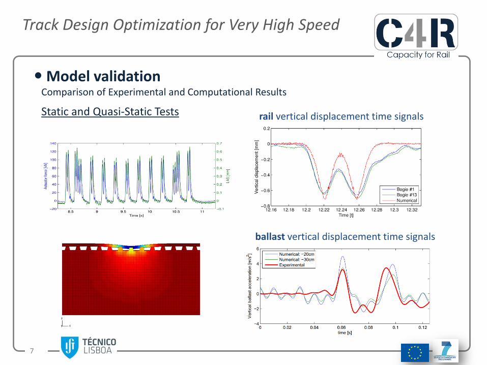
Model validation
Static and Quasi-Static Tests
Comparison of Experimental and Computational Results
rail vertical displacement time signals
ballast vertical displacement time signals
Track Design Optimization for Very High Speed
8
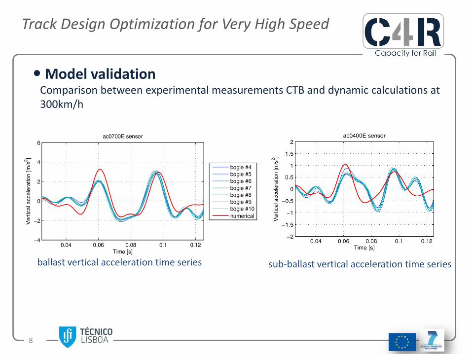
Model validationComparison between experimental measurements CTB and dynamic calculations at 300km/h
ballast vertical acceleration time series sub-ballast vertical acceleration time series

Track Design Optimization for Very High Speed
9
Train speed influence on CTB track case
Dynamic calculations of CTB track reference case : influence of train speed increase from 300 to 400 km/h
Peak vertical acceleration values within the ballast layer
Track response overview for VHS

Track Design Optimization for Very High Speed
10
Track response overview for VHS
Track response overview: key aspects
− Input parameters: rail pad and USP vertical stiffness
− Design space bounds
Rail pads: 20 kN/mm to 200 kN/mm
USPs: 20kN/mm to 500 kN/mm
− Circulation speeds: 300, 350 and 400km/h.
− Multi-objective minimization problem
Minimize peak vertical acceleration levels within ballast layer and sleepers
− DIRECT algorithm (IST version with support for multi-objective optimization)
− Simulation data used generate response surfaces

Track Design Optimization for Very High Speed
11
Track response overview for VHS
Sleeper and ballast max accelerations: 300km/hinfluence of rail pad and USP vertical stiffness (kpad, kusp)
kpad
kusp
kpad
kusp

Track Design Optimization for Very High Speed
12
Track response overview for VHS
Sleeper and ballast max accelerations: 350km/hinfluence of rail pad and USP vertical stiffness (kpad, kusp)
kpad
kusp
kpad
kusp
Track Design Optimization for Very High Speed
13
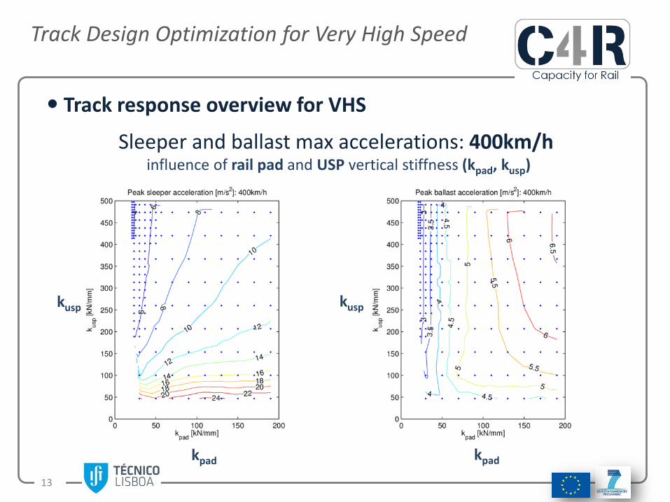
Track response overview for VHS
Sleeper and ballast max accelerations: 400km/hinfluence of rail pad and USP vertical stiffness (kpad, kusp)
kpad
kusp
kpad
kusp

Track Design Optimization for Very High Speed
14
Track response overview for VHS
− Peak sleeper acceleration Decrease with increased kusp
Sensitivity is higher when kusp is lowPeak values are very high when kusp is lowQualitatively, the link between peak vertical vibration levels and the design parameters (vertical stiffness of rail pads and USPs) is observed on all circulation speeds.
− Peak ballast accelerationInsensitive to kusp, except when kusp values are very low Sensitive to kpad
− CautionNo real in situ data on USP tracksNo measurements from VHS trains at 400km/h
Influence of rail pad and USP vertical stiffness variations (kpad, kusp)
Remarks

15
Test reference Kpad[kN/mm]
Kusp[kN/mm]
Variant description
Notes
Test 1 100 - M(100,-) Reference Track box CTB
Test 2 40 - M(40,-)Test 3 60 - M(60,-)Test 4 40 80 M(40,80) Test 2 + USP
Test 5 60 80 M(60,80) Test 3 + USP
80 80 M(80,80) Additional variant
Test 1 + USP 100 80 M(100,80) Reference CTB + USP
60 200 M(60,200) Additional variant
60 500 M(60,500) Additional variant
80 50 M(80,50) Additional variant
100 50 M(100,50) Additional variant
Track Design Optimization for Very High Speed
USP
Track design optimization for VHS
Railpads
Under sleeper pad (USP)
TEST plan support CEDEX to prepare tests in the CTB; coordination with other partners
➢ Track design variants to be tested: combinations of Railpads+USPs
• Compute dynamic simulations of the passage of a train circulating at high and very-high speeds on each track variant
• Evaluate peak acceleration levels observed in the track (in particular ballast layer and on the sleepers)
➢ Optimized Design to enhance track dynamic performance, controlling and reducing track vibrations with speed increase
M(kpad, kusp)

Track Design Optimization for Very High Speed
16
Track design optimization for VHS
Parametric study Rail pad stiffness kpad [kN/mm] 40, 60, 80, 100
USP stiffness kusp [kN/mm] 40, 60, 80, 100
Train speed v [km/h] 300, 320, 330, 350, 360, 380, 400
Comparisons of ballast and sleepers vertical acceleration time series for 300 km/h
Railpad+USP
Track Design Optimization for Very High Speed
17
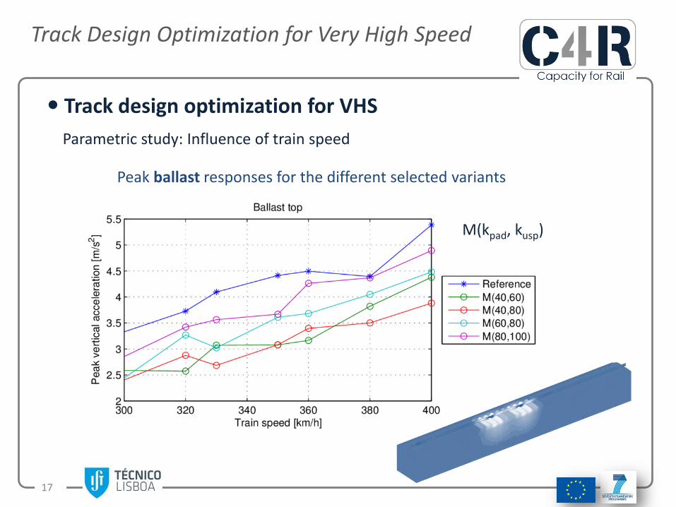
Track design optimization for VHS
Parametric study: Influence of train speed
Peak ballast responses for the different selected variants
M(kpad, kusp)
Track Design Optimization for Very High Speed
18
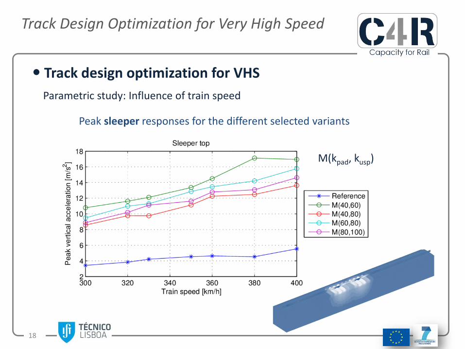
Track design optimization for VHS
Parametric study: Influence of train speed
Peak sleeper responses for the different selected variants
M(kpad, kusp)

Track Design Optimization for Very High Speed
19
Track design optimization for VHS
Parametric study
Relative reductions in peak ballast accelerations with regards to the reference model
Track Design Optimization for Very High Speed
20
Final Remarks
✓ The introduction of USPs results in a significant reduction in peak verticaldisplacement and acceleration levels within the track supporting layers,ballast layer included, for all the track design solutions tested.
✓ However, it must be highlighted that these improvements are accompaniedby increases in peak vertical displacement and acceleration levels on trackcomponents supported by the USPs, as the rails and the sleepers.
✓ Notwithstanding, the results also suggest that incorporating stiffer USPs mayreduce peak acceleration levels within the ballast layer while preservingpeak sleeper acceleration levels.

Track Design Optimization for Very High Speed
21
Final RemarksAlong the interpretation and critical analysis of the results attention must be paidto the following:
✓ The numerical model is not able to consider the following positive effectsknown already to be provided by USPs:
• increase in the interface and load-distributing area between sleepers and ballast
• embedding effect of the ballast stones by the USP elastic layer
✓ Any results obtained for trains speeds of 400km/h must be taken with care as novalidation with real measurements was made at these speeds;
✓ The numerical results here analysed are provided exclusively from short termcomputations, that is, only track instantaneous responses are obtained, so,conclusions cannot be directly extrapolated to track long-term performance norwithin a life cycle analysis perspective;