
1
Carbon Nanotube Biosensor for the Assessment of Personal
Quality of LifeKatsuyuki Murata1, Masuhiro Abe2, Yasuo Ifuku3, Atsuhiko Kojima4, Mitsuaki Shimuzu5, Masatoshi Maeda6, Tatsuaki Ataka1, Kazuhiko Matsumoto7
1 Olympus Corpration, CREST-JST and NEDO, 2 NEDO, 3 Mitsubishi Kagaku Iatron, 4 Mitsubishi
Chemical, 5 AIST, 6 Tsukuba University, 7 NEDO, Osaku University, CREST-JST, and AIST
2
ProlegomenonQuotation from our HP
• Future Creation Laboratory of Olympus Corporation– Our goal: enhancement quality of life (QOL)
on mind and body– The Future Creation Laboratory is committed
to pursuing a variety of research projects aimed at identifying and creating future values for enriching people's lives.
3
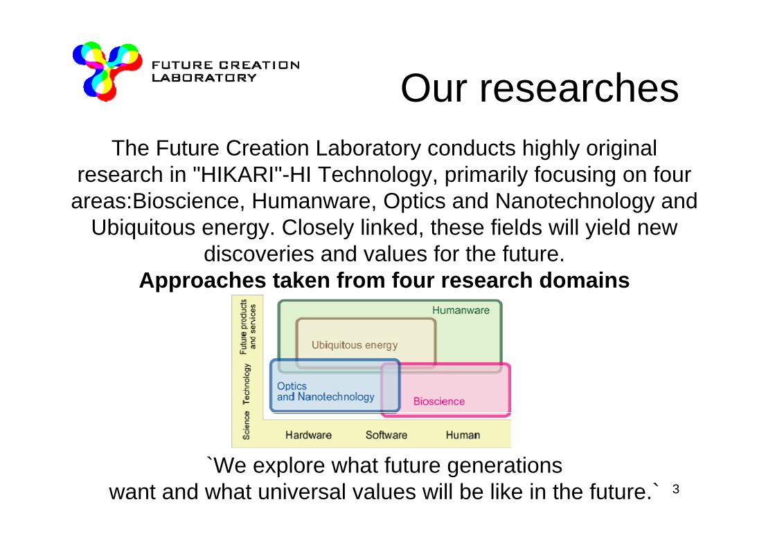
Our researchesThe Future Creation Laboratory conducts highly original
research in "HIKARI"-HI Technology, primarily focusing on four areas:Bioscience, Humanware, Optics and Nanotechnology and
Ubiquitous energy. Closely linked, these fields will yield new discoveries and values for the future.
Approaches taken from four research domains
`We explore what future generations want and what universal values will be like in the future.`

4
Bioscience domain-Enhance QOL on mind and body-
Our future dreams and goal
In the area of carbon nanotube(CNT) biosensors research, we are attempting to establish a technology that allows the ultrasensitive measuring (so called “single molecule detection”) of biomolecules by applying the CNT single electron transistor to biosensors.This technology will open a new possibility for home physical check-ups and will contribute to preventive medicine and health management during recovery.
5
IntroductionWhat is Personal QOL
This project is “Research and Development of Nanodevices for
Practical Utilization of Nanotechnology” in NEDO

6
Challenge to nanotechnology of Olympus
1980
1990
2000
Reinforcement of core competence
A c
halle
nge
and
deve
lopm
ent t
o a
front
ier
2010Nano
measurementNano medical
device
Many functions Capsule
Precisely
microMicro machine
capsule endoscope
AFMcantilever
biolever
MEMS scanner
Nanobio
living body imitation sensor
end microscope

7
WebPDF file ;21C US security in the 21st centryCurrent Japan is
super aged society
Japan → World
Country of currentaged society: about 10
20 years past:about 20
We take the fastest problem of aging speed underhand

8
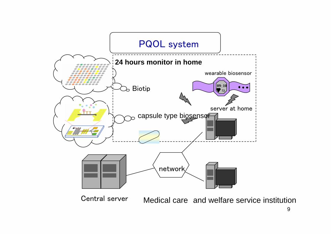
Personal QOL system~Aims to reduce medical cost and promote healthy
intentions~
market size10trillion yenin Japan
200-300trillion yenin the world
Preventivemedicine Diagnosis Treatment
Postoperativecarecurrent
future
Personal QOL system
•Feature•24 hours monitor with a terminal in home•Biotip, microTAS
at home at hospital at home
9
24 hours monitor in home
server at home
network
7209:10
wearable biosensor
Biotip
capsule type biosensor
PQOL system
Central server Medical care and welfare service institution

10
抗体
カーボンナノチューブソース ドレイン
抗体
カーボンナノチューブソース ドレイン
CNTSource Drain
Target molecule
CNT-FET
Bioaffinity imaging MicroTAS
中央サーバ
Cupcel
diagnosis tip
Network
DNA direct reading NEWBiotip
Biosensor array
Enhancement of QOL (at-home distant place medical care)
PQOL systemClaim success for introducing
new measurement system
SPM for Bio
Social value
Economic value
Economic value72
09:1072
09:10
11
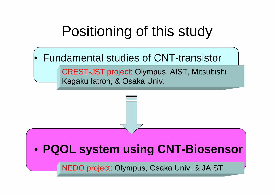
• Fundamental studies of CNT-transistor
• PQOL system using CNT-Biosensor
Positioning of this study
CREST-JST project: Olympus, AIST, Mitsubishi Kagaku Iatron, & Osaka Univ.
NEDO project: Olympus, Osaka Univ. & JAIST

12
• CREST-JST Project
• Mainly fundamental research– CNT-field effect
transistor (FET)– using CNT-FET in
biosensor
• NEDO Project
• Investigation for practical use– measure yield, ,
quantifiability, selectivity, sensitivity, stability, reliability Establishment of micro total analysis system (TAS) by MEMS technology
Relationship between JST & NEDO Project

13
Position of CNT biosensors in CNT applications
Hydrogen storage
Catalyst
Electrode of Fuel cell
Capacitor
Filed emission
DDS
FET
STM tip
Mass-production method of CNTs must be established
CNTs not required in large quantities

14
Contents of this presentation
• What is CNT biosensor?• Problems for practical use and solutions
15
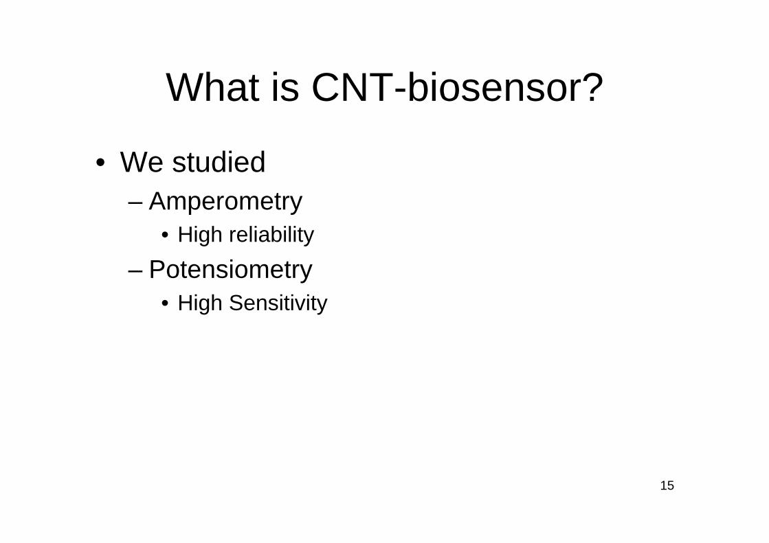
What is CNT-biosensor?
• We studied– Amperometry
• High reliability– Potensiometry
• High Sensitivity

16
抗体
カーボンナノチューブ
ソース ドレイン
CNT
抗体
Potensiometry
antibody
Target molecules
CNT
Source Drain
CNT
antibody
Amperometry(Large surface area electrode) (FET)
CNT biosensor of Amperometry or Potensiometry
17
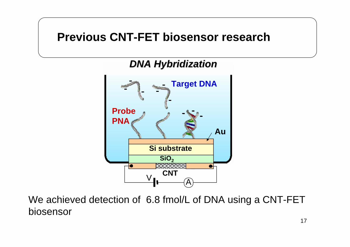
ProbePNA
Target DNA
DNA HybridizationDNA Hybridization
CNTV A
Au
Si substrateSiO2
We achieved detection of 6.8 fmol/L of DNA using a CNT-FET biosensor
Previous CNT-FET biosensor research

18microTAS
Biosensor array
マルチプレクサー
マルチプレクサー
多項目アレイ
抗体
カーボンナノチューブ
ソース ドレイン
抗体
Potentiometry
atnibody
Target molecule
CNT
Source Drain
CNT
antibody
Amperometry
pretreatment
specimen injection
19
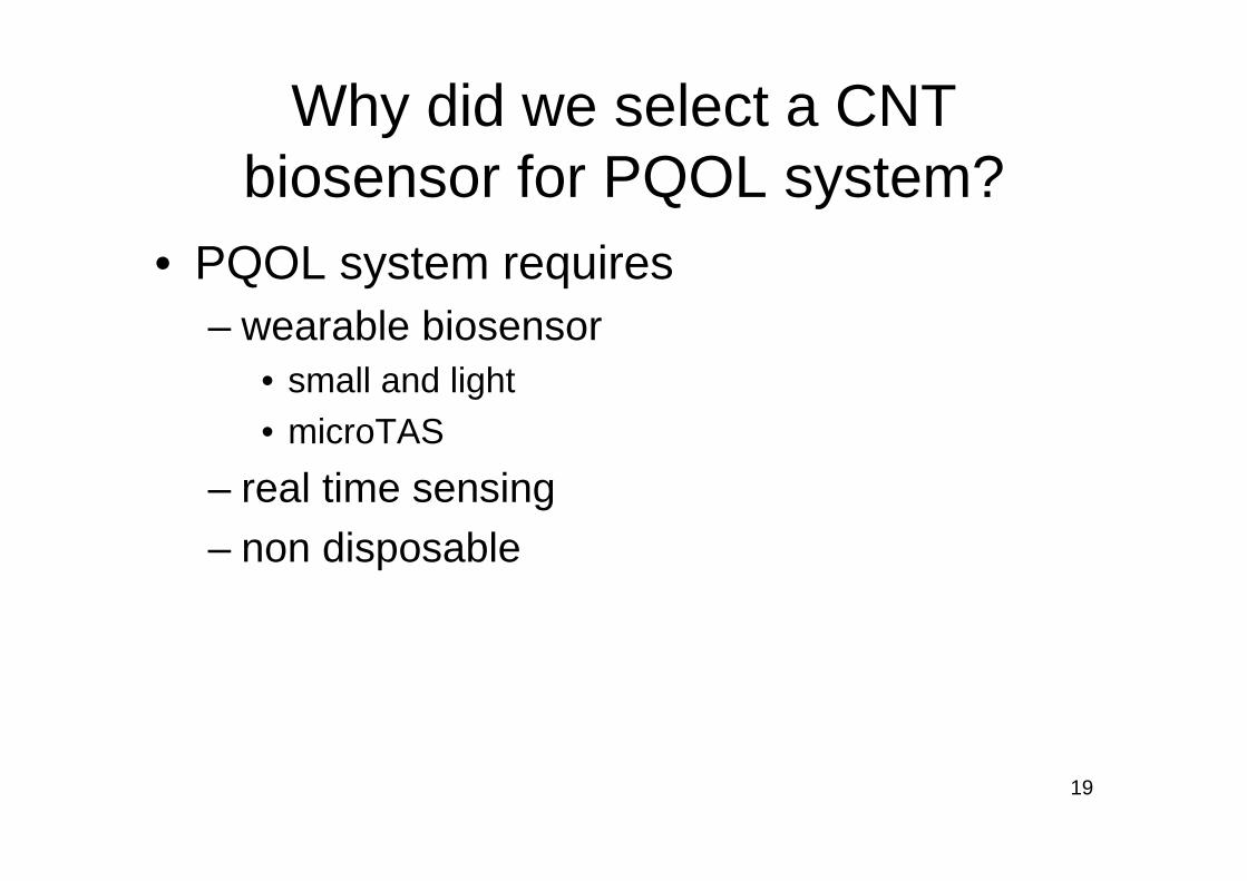
Why did we select a CNT biosensor for PQOL system?
• PQOL system requires– wearable biosensor
• small and light• microTAS
– real time sensing– non disposable

20
CNT biosensor compared with conventional protein sensing methods
yesnoyessensor array
nonoyesNot disporsable?
nonoyesReal time sensing
noyesyesMobility
most high sensitivitynmol/l orderc.a. 1μmol/l
conventional study
Sensitivity
Chemical luminescence ChromatographyCNT Biosensor

21
Problems for practical use of CNT-FET based biosensor
• CREST-JST– Fundamental design– Stability & reliability
• NEDO– Quantifiability– Sensitivity– Yield– Selectivity

22
Contamination provides less stability of CNT-FET
Washing CNT using aproticsolvent

23
What is DMSO & DMAC
• aprotic solvent– Dimethylsulfoxide(DMSO)– Dimethyl acetamide(DMAC)
O
S
Me Me
O
Me C N
Me Me

24
Aprotic solvent features
• hydrophobic• hydrophilic
– strong dipole moment– strong nucleophilicity(basic)
25
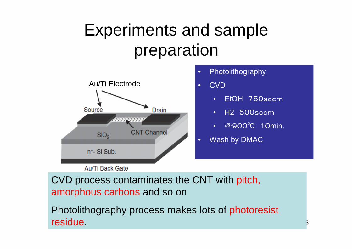
Experiments and sample preparation
Au/Ti Electrode• Photolithography
• CVD
• EtOH 750sccm
• H2 500sccm
• @900℃ 10min.
• Wash by DMAC
CVD process contaminates the CNT with pitch, amorphous carbons and so on
Photolithography process makes lots of photoresistresidue.
26
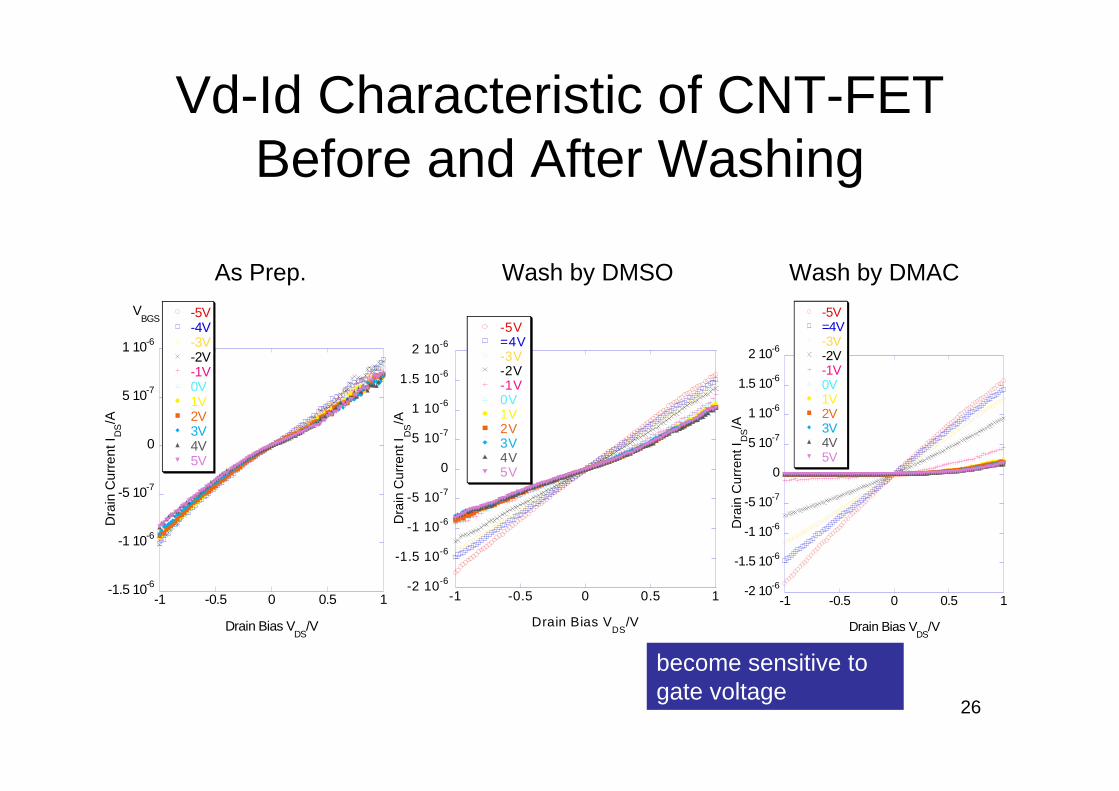
Vd-Id Characteristic of CNT-FET Before and After Washing
-1.5 10-6
-1 10-6
-5 10-7
0
5 10-7
1 10-6
-1 -0.5 0 0.5 1
-5V-4V-3V-2V-1V0V1V2V3V4V5V
Dra
in C
urre
nt I D
S/A
Drain Bias VDS
/V
VBGS
-2 10-6
-1.5 10-6
-1 10-6
-5 10-7
0
5 10-7
1 10-6
1.5 10-6
2 10-6
-1 -0.5 0 0.5 1
-5V=4V-3V-2V-1V0V1V2V3V4V5V
Dra
in C
urre
nt I D
S/A
Drain Bias VDS
/V
-2 10-6
-1.5 10-6
-1 10-6
-5 10-7
0
5 10-7
1 10-6
1.5 10-6
2 10-6
-1 -0.5 0 0.5 1
-5V=4V-3V-2V-1V0V1V2V3V4V5V
Dra
in C
urre
nt I D
S/A
Drain Bias VDS
/V
As Prep. Wash by DMSO Wash by DMAC
become sensitive to gate voltage

27
Results: top gate is best structure
• CNT must be kept clean for optimal CNT-FET performance
• Top-gate CNT-FET biosensor– CNT kept clean because CNT is covered with
SiNx.

28
Top-gate CNT-FET illustration
SiNx
SiO2
Si
Drain(AU/Ti) Source (Au/Ti)
metal cat. (Co)
Resin Top Gate (Au/Ti) 10000 mm2
Carbon nanotube

29
Top-gate structure prevents adsorbing contamination on CNT
Water, oxygen and other contaminates cannot adsorb on CNTs

30
Top-gate CNT-FET has high stability
open airPrevious work
Our top-gate device
time/sec.
Little change in drain current
31
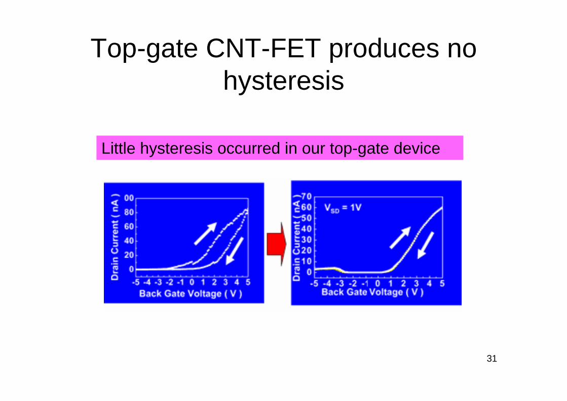
Top-gate CNT-FET produces no hysteresis
Little hysteresis occurred in our top-gate device

32
Top-gate CNT biosensor has low sensitivity

33
Why low sensitivity?
• No modulation by schottky barrier
Top-gate FET was modulated by only channel part, back gate FET was modulated by schottky barrier and channel part.
Schottky barrier

34
Double gate structure enhances CNT-FET sensitivity
SiNx
SiO2
Back Gate
Si
Drain Source
Metal cat.
resinTop Gate
Carbon nanotube
top-gateCNT-FET

35
Double gate enhances sensitivity
-6 10-9
-4 10-9
-2 10-9
0
2 10-9
4 10-9
6 10-9
-1.5 -1 -0.5 0 0.5 1 1.5
+0.10 V+0.08 V+0.06 V+0.04 V+0.02 V0 V-0.02 V-0.04 V-0.06 V-0.08 V-0.10 V
Dra
in C
urre
nt/ A
Tap gate voltage/ V
High sensitivity
Back gate voltage
-5 V 0 V 5 V

36
Biosensing
CNT-FET can sense proteins based on antigen-antibody
reaction

37
Immobilizing PSA on Top-gate
a-PSA + 10 mM Phosphate buffer (pH 7.4)Top Gate
Phosphate buffer, including a-PSA, was dropped on a top gate of CNT-FET.a-PSA was physically adsorbed on top-gate.
Pig Serum Albumin (PSA)anti-Pig serum albumin (a-PSA)
a-PSA was immobilized on CNT-FET, and PSA in solution was sensed.
Proteins
Experimentalfixation of protein
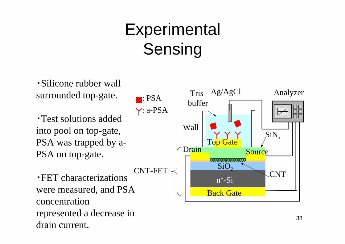
38
・Silicone rubber wall surrounded top-gate.
・Test solutions added into pool on top-gate, PSA was trapped by a-PSA on top-gate.
・FET characterizations were measured, and PSA concentration represented a decrease in drain current.
Ag/AgCl
Back Gate
SourceTop Gate
: a-PSA: PSA
Wall
SiO2
n+-Si
SiNx
Tris buffer
CNTCNT-FET
Analyzer
Drain
ExperimentalSensing

39
Top Gate Voltage [V]
-1 +10
25
20
15
10
5
0
24
20
16+0.5 +1+0.75
Top Gate Voltage [V]
Dra
in C
urr
ent
[nA
]
Dra
in C
urr
ent
[nA
]
BiosensingBack Gate Voltage: +5 VDrain Voltage: +0.1 V0.1 M Tris Buffer (pH = 8.0)
ID – VTG curve
拡大図
0.19 V
0 nmol/l PSA70 nmol/l PSA700 nmol/l PSA7000 nmol/l PSA15000 nmol/l PSA

40
Drain Voltage: +0.1 VTop Gate Voltage: +1 V
Relationship between drain current change and PSA concentration
10 102
Added PSA conc. [nmol/l]
-⊿
I D[n
A]
2
1.5
1
0.5
0
-⊿ID vs. PSA concentration
sensitivity limit: 20 nmol/l
Back Gate Voltage: +5 V0.1 M Tris Buffer (pH = 8.0)
103 104 105
It is the highest sensitivity of the kinds type CNT biosensor.
Sensitivity is possibility to improve with amount of added PSA or top-gate electrode area.
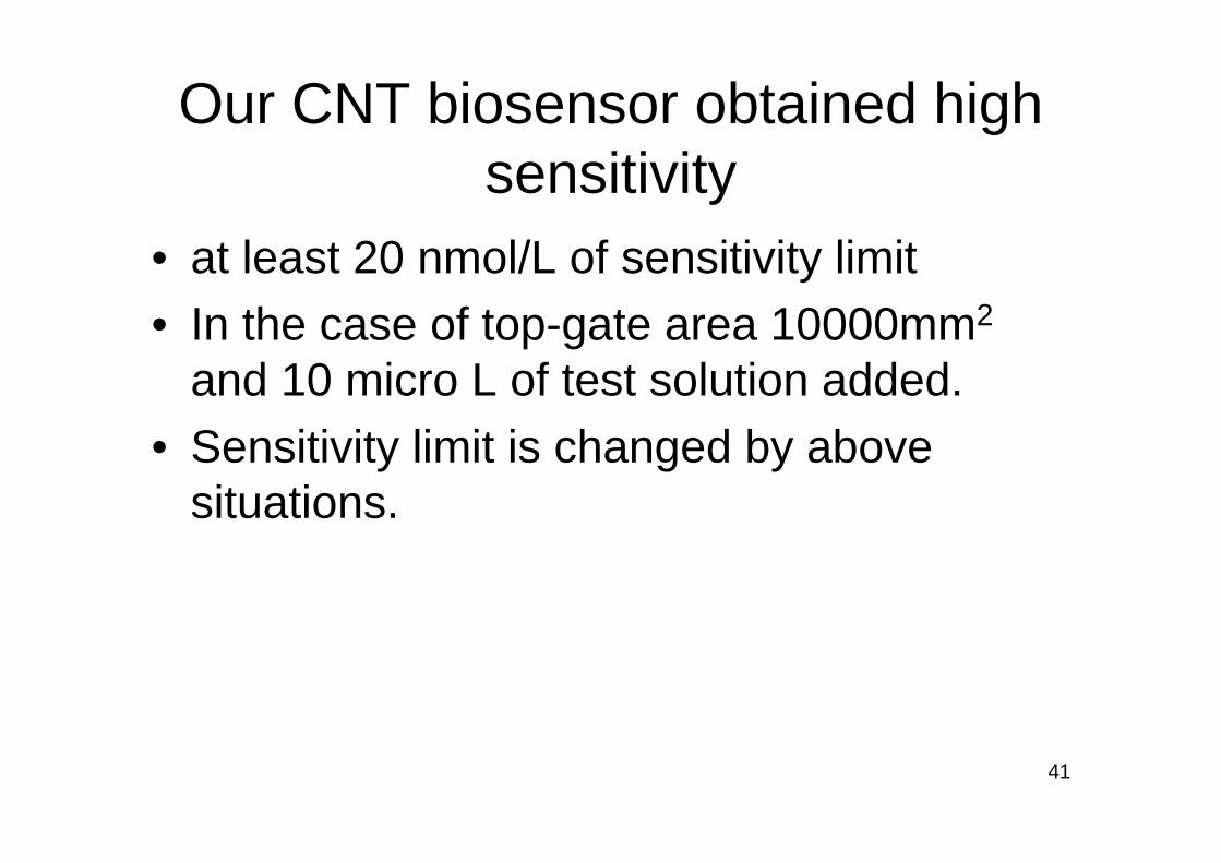
41
Our CNT biosensor obtained high sensitivity
• at least 20 nmol/L of sensitivity limit • In the case of top-gate area 10000mm2
and 10 micro L of test solution added.• Sensitivity limit is changed by above
situations.

42
Our device can be used consecutively after washing process

43
Selective protein sensing for CNT biosensor
First reported study of selective protein sensing

44
CNT-FET Biosensor Problems Do we really observe antigen-antibody reaction?
Top GateTop Gate
A B
C
If protein selectivity is not confirmed, we cannot be sure of sensing by non-specific adsorption

45
CNT-FET immobilized a-PSA(PSA biosensor)
CNT-FET immobilized a-MIgG(MIgG biosensor)
a-PSA a-MIgG
Biosensors
Selective protein detection
(MIgG:Mouse immunoglobulin G)

46
・Test solution (shown below) was poured on top-gate of PSA biosensor or MIgG biosensor.
・FET drain current measured, and PSA or MIgGconcentration represented a decrease in drain current. .
Test solutions: Tris buffer without antigensTris buffer containing PSATris buffer containing MIgGTris buffer containing both PSA and MIgG
Selective detection of protein

47
Drain current decrease at PSA biosensorDrain Voltage: +0.1 V Top Gate Voltage: +1 VBack Gate Voltage: +5 V Solution:0.1 M Tris Buffer (pH = 8.0)
Antigen concentration [nmol/l]
2
1
0
100 1000 10000
PSA
MIgG
PSA+MIgG
20
PSA [nmol/l]
Table. Drain current of PSA biosensor which antigen solution was poured.
Drain current [nA]
MIgG [nmol/l]
23.840023.85700023.4707022.72070022.9770070021.9207000
a-PSA
PSA MIgG
PSA
MIgG
a-PSA
-⊿I D
[nA
]
-⊿ID - PSA concentration curve
At PSA biosensorOnly PSA detectedMIgG was not detected

48
MIgG concentration [nmol/l]
-⊿I D
[nA
]
6
2
0
100 1000 10000
PSA
MIgGPSA+MIgG
20
4
Drain current decrease at MIgG biosensorDrain Voltage: +0.1 V Top Gate Voltage: +1 VBack Gate Voltage: +5 V Solution:0.1 M Tris Buffer(pH = 8.0)
PSA [nmol/l]
Table. Drain current of PSA biosensor which antigen solution was poured.
Drain current [nA]
MIgG [nmol/l]
106.5900103.087000101.4370000106.540700103.10700700
-⊿ID - MIgG concentration curve
a-MIgG
PSA MIgG PSA
MIgG
a-MIgG
At MIgG biosensorOnly MIgG was detectedPSA was not detected.

49
Conclusion
・We successfully achieved real-time sensing and selective detection of proteins using top-gate CNT-FET.
• Our CNT biosensor demonstrated high sensitivity, high stability, and selectivity.
• CNT biosensors have potential uses as industrial product.


