Q3.5
-SS
DE
LI
SE
LF
SE
RV
ICE
CA
SE
INS
TA
LL
AT
ION
& O
PE
RA
TIO
N G
UID
E
/CHINO
Q3.5-SS
DELI SELF SERVICE
CASE
REV. 0218
Installation
& Operation
Manual
2
/CHINOA publication of HUSSMANN® Chino
13770 Ramona Avenue • Chino, California 91710
(909) 628-8942 FAX
(909) 590-4910
(800) 395-9229
www.hussmann.com
1. General Instructions
This Booklet Contains Information on:
Q3.5-SS refrigerated, service deli merchandiser.
Shipping Damage
All equipment should be thoroughly examined for shipping damage before and during
unloading.
This equipment has been carefully inspected at our factory and the carrier has assumed
responsibility for safe arrival. If damaged, either apparent or concealed, claim must
be made to the carrier.
Apparent Loss or Damage
If there is an obvious loss or damage, it must be noted on the freight bill or express
receipt and signed by the carrier’s agent; otherwise, carrier may refuse claim. The
carrier will supply necessary claim forms.
Concealed Loss or Damage
When loss or damage is not apparent until after all equipment is uncrated, a claim for
concealed damage is made. Make request in writing to carrier for inspection within 15
days, and retain all packaging. The carrier will supply inspection report and required
claim forms.
Shortages
Check your shipment for any possible shortages of material. If a shortage should exist
and is found to be the responsibility of Hussmann Chino, notify Hussmann Chino. If
such a shortage involves the carrier, notify the carrier immediately, and request an
inspection. Hussmann Chino will acknowledge shortages within ten days from receipt
of equipment.
Hussmann Chino Product Control
The serial number and shipping date of all equipment has been recorded in Hussmann’s
fi les for warranty and replacement part purposes. All correspondence pertaining to
warranty or parts ordering must include the serial number of each piece of equipment
involved, in order to provide the customer with the correct parts.
Keep this booklet with the case at all times for future reference.

3
2. Table of Contents
1. General Instructions...............................................................2
2. Table of Contents ...................................................................3
3. Cut and Plan Views ................................................................4
4. Installation...............................................................................5
5. Plumbing .................................................................................8
6. Refrigeration ...........................................................................8
7. Spec Sheet ..............................................................................9
8. Electrical................................................................................10
9. Finishing Touches ................................................................11
10. User Information .................................................................12
11. Maintenance ........................................................................13
12. Wiring Diagrams index .......................................................15
13. Wiring Diagrams .................................................................16
14. Troubleshooting Guide ......................................................17
15. Appendices .........................................................................19

4
3. Cut and Plan Views
10 (254)
101/8 (257)
331/2 (851)
14 (356)
18 (457)
Q3.5-SS Multi-Deck Self-Service
21 (533)
577/8(1470)
263/4 (679)
223/4 (578)
30 (762)
291/2 (749)
435/8 (1108)
155/8 (397)
101/8 (257)
51/8 (130)
11 (279)2 (51)
2 (51) 11 (279)
Q3.5-SS Floral Self-Service
123/4 (324)
471/8(1197)
263/4 (679)
121/4 (311)
191/2 (495)
291/2 (749)
435/8 (1108)
331/2 (851)
8(203)
Elec
Case Leg
Front Close-Off
Back Close-Off
DrainRefrig
5(127)
6 1/8(156)
CL
44(1135)
30 3/4(781)
24 5/8(625)
27 5/8(702)
48 (VARIABLE)(1219)
Q3.5-SS
EndPanels
11/8 (29)
Notes:
Contact your sales representative for information on
possible availability of additional case lengths.
5/8 Elec
Customer Side
Drain
RefrigCL
44(1135)
9(229)
43/8(111)
72 1/4(1835)
Q3.5-SS 90º O/S
9(229)
17(432)
23(584)
131/4(337)
End Panels11/8 (29)
90° OutsideWedge
5/8
9(229)
4 3/8
(111)Elec
Customer Side
Drain
Refrig
CL
44(1135)
39 1/8(994)
26 1/8(664)
13 3/8(340)
23(584)
Q3.5-SS 45º O/S
47/8(123)
EndPanels
11/8 (29)
45° Outside Wedge
5/8
5
LocationThe refrigerated merchandisers have been designed
for use only in air conditioned stores where temperature
and humidity are maintained at or below 75°F and 55%
relative humidity. DO NOT allow air conditioning, electric
fans, ovens, open doors or windows (etc.) to create air
currents around the merchandiser, as this will impair its
correct operation.
Product temperature should always be maintained at
a constant and proper temperature. This means that
from the time the product is received, through storage,
preparation and display, the temperature of the product
must be controlled to maximize life of the product.
Uncrating the StandPlace the fi xture as close to its permanent position as
possible. Keep in place, attached case until ready to set/
bolt to adjoining case.
Tighten Glass ScrewsTighten screws along clamshell located on the underside
of glass before placing unit into operation.
Exterior LoadingThese models have not been structurally designed to
support excessive external loading. Do not walk on
their tops; This could cause serious personal injury and
damage to the fi xture.
Setting and JoiningThe sectional construction of these models enable them
to be joined in line to give the effect of one continuous
display.
An Alignment pin kit is supplied with every case and
must be used in alignment.
LevelingIMPORTANT! IT IS IMPERATIVE THAT CASES
BE LEVELED FROM FRONT TO BACK AND SIDE
TO SIDE PRIOR TO JOINING. A LEVEL CASE IS
NECESSARY TO INSURE PROPER OPERATION,
WATER DRAINAGE, GLASS ALIGNMENT AND
OPERATION OF THE HINGES SUPPORTING THE
GLASS. LEVELING THE CASE CORRECTLY WILL
SOLVE MOST HINGE OPERATION PROBLEMS.
Note: A. To avoid removing concrete fl ooring, begin lineup
leveling from the highest point of the store fl oor.
B. When wedges are involved in a lineup, set them fi rst.
All cases were leveled and joined prior to shipment to
insure the closest possible fi t when cases are joined in
the fi eld. When joining, use a carpenters level and adjust
legs accordingly. The legs on the Q3.5-SS are adjustable
and do not require shims. Simply screw the leg up or
down to adjust height.
1. Using case blueprints, measure off and mark on the
fl oor the exact dimensions of where the cases will
sit. Snap chalk line for front and back positions of
base rail or pedestal. Mark the location of each joint
front and back. Find the highest point throughout
the lineup. FLOORS ARE NORMALLY NOT LEVEL!
Determine the highest point of the fl oor; cases will
be set off this point. All cases in the entire lineup
must be brought up to the highest level of the case
sitting at the highest point in the lineup. This may be
done a few different ways.
a) Walk the fl oor looking for any mounds or dips.
b) Use a string level.
c) Use a transit.
If a wedge is used in the middle of a lineup, the
wedge must be set on the highest point on the fl oor
FIRST, with the rest if the lineup being leveled from
it. The Q3.5-SS case has adjustable legs to allow for
leveling.
2. Set fi rst case over the highest part of the fl oor and
adjust legs so that case is level. Remove side and
back leg braces after case is set and joined.
3. Set second case within one foot (1') of the fi rst case,
and remove leg skids. Keep the supports along the
length of the case and far end of case. Level case to
the fi rst using the instructions in step one.
4. Apply masking tape 1/8" in from end of case on
inside and outside rear mullion and body work on
both cases to be joined.
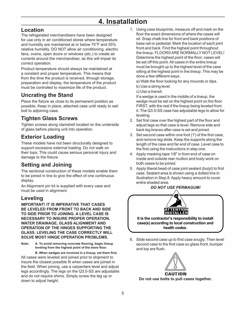
5. Apply liberal bead of case joint sealant (butyl) to fi rst
case. Sealant area is shown using a dotted line in
illustration in Step 8. Apply heavy amount to cover
entire shaded area.
DO NOT USE PERMAGUM!
It is the contractor’s responsibility to install
case(s) according to local construction and
health codes.
6. Slide second case up to fi rst case snugly. Then level
second case to the fi rst case so glass front, bumper
and top are fl ush.
Do not use bolts to pull cases together.
4. Insatallation
6
Installation (Cont'd)
7. To compress butyl at joint, use two Jurgenson wood
clamps. Make sure case is level from front to back
and side to side on inside bulkheads at joint.
8. Attach sections together via the bolts pictured in the
illustration below.
9. Apply bead of butyl to top of bulk heads and slip on
stainless steel bulkhead cap. Also apply silicone to
seam between joints.
10. Use fi nger to smooth silicone as thin as possible at
masking tape on inside and outside of rear mullion
(apply additional silicone if necessary). Remove
tape applied on line #4.
11. Remove front, back and end shipping braces.
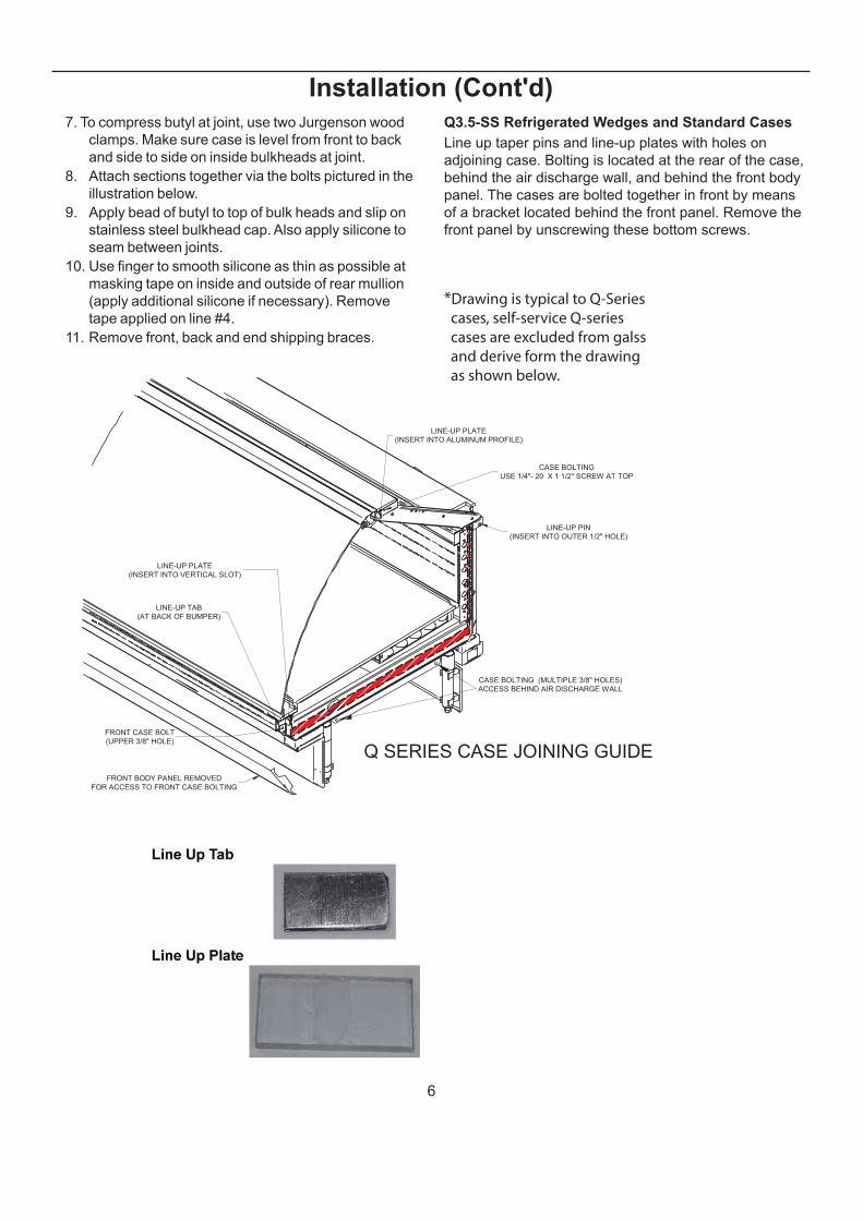
Q3.5-SS Refrigerated Wedges and Standard Cases
Line up taper pins and line-up plates with holes on
adjoining case. Bolting is located at the rear of the case,
behind the air discharge wall, and behind the front body
panel. The cases are bolted together in front by means
of a bracket located behind the front panel. Remove the
front panel by unscrewing these bottom screws.
FRONT BODY PANEL REMOVED
FOR ACCESS TO FRONT CASE BOLTING
FRONT CASE BOLT
(UPPER 3/8" HOLE)
LINE-UP PLATE
(INSERT INTO ALUMINUM PROFILE)
LINE-UP PLATE
(INSERT INTO VERTICAL SLOT)
LINE-UP PIN
(INSERT INTO OUTER 1/2" HOLE)
CASE BOLTING (MULTIPLE 3/8" HOLES)
ACCESS BEHIND AIR DISCHARGE WALL
CASE BOLTING
USE 1/4"- 20 X 1 1/2" SCREW AT TOP
Q SERIES CASE JOINING GUIDE
LINE-UP TAB
(AT BACK OF BUMPER)
*Drawing is typical to Q-Series
cases, self-service Q-series
cases are excluded from galss
and derive form the drawing
as shown below.
7
Installation (Cont'd)
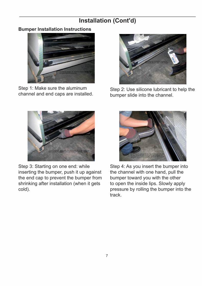
Bumper Installation Instructions
Step 1: Make sure the aluminum
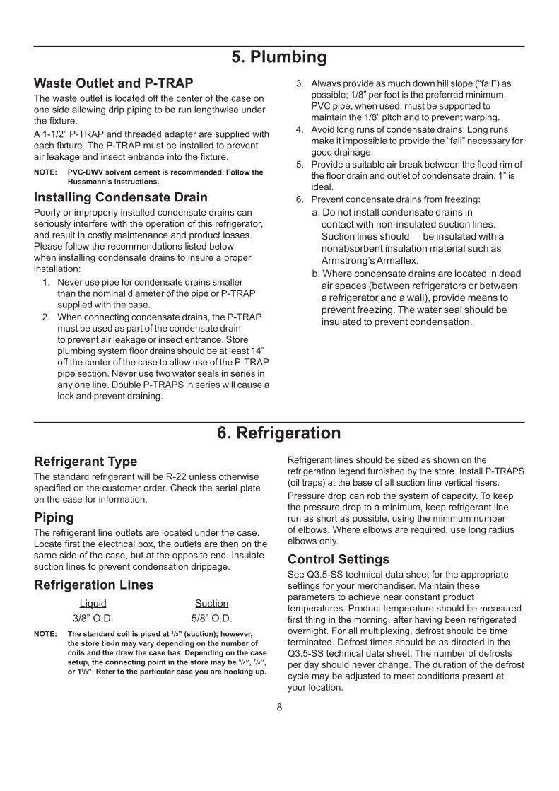
channel and end caps are installed.Step 2: Use silicone lubricant to help the
bumper slide into the channel.
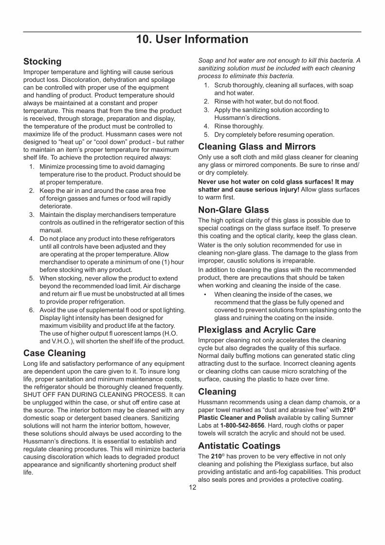
Step 3: Starting on one end: while
inserting the bumper, push it up against
the end cap to prevent the bumper from
shrinking after installation (when it gets
cold).
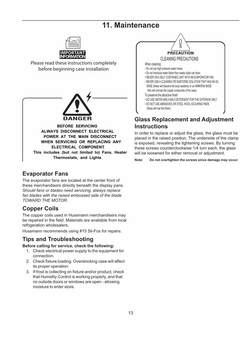
Step 4: As you insert the bumper into
the channel with one hand, pull the
bumper toward you with the other
to open the inside lips. Slowly apply
pressure by rolling the bumper into the
track.
8
5. Plumbing
Waste Outlet and P-TRAPThe waste outlet is located off the center of the case on
one side allowing drip piping to be run lengthwise under
the fi xture.
A 1-1/2” P-TRAP and threaded adapter are supplied with
each fi xture. The P-TRAP must be installed to prevent
air leakage and insect entrance into the fi xture.
NOTE: PVC-DWV solvent cement is recommended. Follow the
Hussmann’s instructions.
Installing Condensate DrainPoorly or improperly installed condensate drains can
seriously interfere with the operation of this refrigerator,
and result in costly maintenance and product losses.
Please follow the recommendations listed below
when installing condensate drains to insure a proper
installation:
1. Never use pipe for condensate drains smaller
than the nominal diameter of the pipe or P-TRAP
supplied with the case.
2. When connecting condensate drains, the P-TRAP
must be used as part of the condensate drain
to prevent air leakage or insect entrance. Store
plumbing system fl oor drains should be at least 14”
off the center of the case to allow use of the P-TRAP
pipe section. Never use two water seals in series in
any one line. Double P-TRAPS in series will cause a
lock and prevent draining.
3. Always provide as much down hill slope (“fall”) as
possible; 1/8” per foot is the preferred minimum.
PVC pipe, when used, must be supported to
maintain the 1/8” pitch and to prevent warping.
4. Avoid long runs of condensate drains. Long runs
make it impossible to provide the “fall” necessary for
good drainage.
5. Provide a suitable air break between the fl ood rim of
the fl oor drain and outlet of condensate drain. 1” is
ideal.
6. Prevent condensate drains from freezing:
a. Do not install condensate drains in
contact with non-insulated suction lines.
Suction lines should be insulated with a
nonabsorbent insulation material such as
Armstrong’s Armafl ex.
b. Where condensate drains are located in dead
air spaces (between refrigerators or between
a refrigerator and a wall), provide means to
prevent freezing. The water seal should be
insulated to prevent condensation.
6. Refrigeration
Refrigerant TypeThe standard refrigerant will be R-22 unless otherwise
specifi ed on the customer order. Check the serial plate
on the case for information.
PipingThe refrigerant line outlets are located under the case.
Locate fi rst the electrical box, the outlets are then on the
same side of the case, but at the opposite end. Insulate
suction lines to prevent condensation drippage.
Refrigeration Lines
Liquid Suction
3/8” O.D. 5/8” O.D.
NOTE: The standard coil is piped at 1/2” (suction); however,
the store tie-in may vary depending on the number of
coils and the draw the case has. Depending on the case
setup, the connecting point in the store may be 5/8”, 7/8”,
or 11/8”. Refer to the particular case you are hooking up.
Refrigerant lines should be sized as shown on the
refrigeration legend furnished by the store. Install P-TRAPS
(oil traps) at the base of all suction line vertical risers.
Pressure drop can rob the system of capacity. To keep
the pressure drop to a minimum, keep refrigerant line
run as short as possible, using the minimum number
of elbows. Where elbows are required, use long radius
elbows only.
Control SettingsSee Q3.5-SS technical data sheet for the appropriate
settings for your merchandiser. Maintain these
parameters to achieve near constant product
temperatures. Product temperature should be measured
fi rst thing in the morning, after having been refrigerated
overnight. For all multiplexing, defrost should be time
terminated. Defrost times should be as directed in the
Q3.5-SS technical data sheet. The number of defrosts
per day should never change. The duration of the defrost
cycle may be adjusted to meet conditions present at
your location.

9
SELF-SERVICE DELI REVISION DATE 01/27/17
HUSSMANN - Q3.5-SS-EC (CHINO)
REFRIGERATION DATA:
GPM PSI GPM PSI
NSF 7 AHRI 1200 NSF 7 AHRI 1200 4' 0.5 1.4 3.9 0.1 0.04',5',6',8',10',12' 960 770 20 28 5' 0.7 1.7 6.1 0.2 0.1
90° OS 4420 4420 20 20 6' 0.8 2.1 8.6 0.2 0.2REAR STORAGE 100 90 20 26 8' 1.1 2.7 4.0 0.3 0.4
10' 1.4 3.3 6.9 0.3 0.6**FRONT DISCHARGE AIR MEASURED INSIDE AIR CURTAIN HONEYCOMB 12' 1.6 4.0 7.9 0.4 0.8***REFRIGERATION NOTES: 90° OS 0.4 1.4 3.1 N/A N/A
1) BTU'S DO NOT INCLUDE LIGHTS
2) ADD 10 BTU'S PER FOOT/PER SHELF ROW FOR OPTIONAL LED SHELF LIGHTS
3) AHRI 1200 RATING POINT FOR ENERGY CONSUMPTION COMPARISON ONLY
4) USE DEW POINT FOR HIGH GLIDE REFRIGERANTS. CARE SHOULD BE TAKEN TO USE THE DEW POINT IN P/T TABLES
FOR MEASURING AND ADJUSTING SUPERHEAT. ADJUST EVAPORATOR PRESSURE AS NEEDED TO MAINTAIN THE
DISCHARGE AIR TEMPERATURE SHOWN.
5) RATING CONDITION IS NSF TYPE I, 75°F/55% RH
REFRIGERATION DATA CONTINUED:
FRONT SS DELI 31 28 48 1 1.125
REAR STORAGE SS DELI 35 32 45 2 1.125
ELECTRICAL DATA: STANDARD FANS, HEATERS, LED LIGHTS (115 VOLT)
4' 2 6.7 25 0.2 16 0.3 8 0.2 27 0.3 31 0.5 58 N/A N/A N/A N/A N/A5' 2 6.7 30 0.2 16 0.3 8 0.3 34 0.3 39 0.6 73 N/A N/A N/A N/A N/A6' 4 6.7 20 0.5 32 0.3 8 0.3 39 0.4 46 0.7 84 N/A N/A N/A N/A N/A8' 4 6.7 25 0.5 32 0.3 8 0.5 54 0.5 62 1.0 116 N/A N/A N/A N/A N/A10' 4 6.7 30 0.5 32 0.3 8 0.6 68 0.7 78 1.3 146 N/A N/A N/A N/A N/A12' 6 6.7 25 0.7 48 0.3 8 0.7 81 0.8 93 1.5 173 N/A N/A N/A N/A N/A
90° OS 2 6.7 25 0.2 16 N/A N/A 0.2 18 0.2 21 0.3 39 N/A N/A N/A N/A N/A
OPTIONAL HIGH OUTPUT LED LIGHTS (115 VOLT)
CASE ENERGY USAGE DATA:
AMPS WATTS AMPS WATTS AMPS WATTS
4' 0.3 32 0.4 46 0.7 785' N/A N/A N/A N/A N/A N/A6' N/A N/A N/A N/A N/A N/A8' 0.6 64 0.8 91 1.3 15510' N/A N/A N/A N/A N/A N/A12' 0.8 96 1.2 137 2.0 233
90° OS N/A N/A N/A N/A N/A N/A
LOCATION
OFF TIME 25 6
CASE LENGTH
N/A
# OF END
PNLS
END
PNL
WIDTH
(IN.)
TOTAL ADDED
LENGTH (IN.)
SS DELI 30~34 380~600
0.7
TERM.
TEMP
(°F)
COIL
ONLY
USAGE
20°F GLYCOL
6° RISE
FRONT
20°F GLYCOL
6° RISE
REAR
STORAGE
4',5',6',8',10',12' 3.15 1.88 2.34
CONVENIENCE
OUTLETS (OPTIONAL)
4.2
MAX. LED LOAD
(W/ ALL OPTIONS)
ANTI-SWEAT
HEATERS (ON
FAN CIRCUIT)
DRIP
TIME
1.125
2.25
END PANEL WIDTH KEY
EST.
REFG.
CHRG.
(LBS)
CASE
LENGTHS
90° OS 18.2826 10.44 15.25
AMPS
TDA/V (ft2/ft)
(ft3 wedges)
ACTUAL CDEC
(KWh/day/ft)
(KWh/day wedges)
MAX ALLOWABLE
CDEC (KWh/Day/ft)
(KWh/day wedges)
WATTS AMPS WATTS#
OUTLE
TS
VOLTSAMPS
CASE LENGTH
CANOPY
LIGHTS
H.O. LED
OPTIONAL SHELFMAX. H.O. LED
LOADCASE LENGTH /
WEDGES
AMPS WATTS AMPS WATTS
EVAPORATOR FANS;
SELF-SERVICE SECTION
CANOPY
LIGHTS LED
OPTIONAL LED
SHELF LIGHTS
# OF
EVAP
FANS
BLADE
DIA.
(IN.)
BLADE
PITCH (°)AMPS WATTS
EVAPORATOR
FANS;
REAR STORAGE
AMPS WATTS
SS DELI
DEFROST
WATER
(LBS/DAY/FT)CUT IN
(ºF)
CUT OUT
(ºF)
30~32 200~250
ELEC. THERMOSTAT / AIR
SENSOR SETTINGS DEFROST
TYPE
TIME
(MIN)
DEFROST
FREQUENCY
(#/DAY)
SS DELI 30~32 200~250
CASE LENGTHS/
WEDGES CASE USAGE
RATING CONDITION EVAPORATOR DISCHARGE
AIR ** (°F)
VELOCITY
(FT/MIN)
NSF 7NSF 7
TEMPERATURE (ºF)CAPACITY ***
(BTU/HR/FT) (TOTAL
FOR WEDGES)
7. Spec Sheet

10
8. Electrical
Wiring Color Code
CASE MUST BE GROUNDED
NOTE: Refer to label affi xed to case to determine the actual
confi guration as checked in the “TYPE INSTALLED”
boxes.
Electrical Circuit Identifi cationStandard lighting for all refrigerated models will be full
length LED Lights located within the case at the top.
The switch controlling the lights, the plug provided for
digital scale, and the thermometer are located at the rear
of the case mullion.
The receptacle that is provided on the exterior back
of these models is intended for computerized scales
with a fi ve amp maximum load, not for large motors or
other high wattage appliances. It should be wired to a
dedicated circuit.
BEFORE SERVICING
ALWAYS DISCONNECT ELECTRICAL
POWER AT THE MAIN DISCONNECT
WHEN SERVICING OR REPLACING ANY
ELECTRICAL COMPONENT.
This includes (but not limited to) Fans, Heaters
Thermostats, and Lights
DANGER
.
Field Wiring and Serial Plate
AmperageField Wiring must be sized for component amperes
printed on the serial plate. Actual ampere draw may be
less than specifi ed. Field wiring from the refrigeration
control panel to the merchandisers is required for
refrigeration thermostats. Case amperes are listed on
the wiring diagram, but always check the serial plate.
Ballast LocationBallasts are located within the access panel that runs the
length of the rear of the case.
ASHRAE Color Code
NOTE: All other manufacturers have no standard sensor codes.
Case Control Systems SENSOR COLOR Manufacturer ® > EIL CPC Location Coil Inlet
Color Blue Blue
Part# 225-01-1755 225-01-3255
Coil Outlet Color Red Red Part# 225-01-1757 225-01-3123
Discharge Air Color Green Green
Part# 225-01-1756 225-01-3260
Return Air Color Purple GreenPart# 225-01-1758 225-01-3260
Defrost Term. Color White OrangePart# 225-01-0650 225-01-3254
Liquid Line Color White BluePart# 225-01-0650 225-01-3255

11
9. Finishing Touches
Bumper Installation Tips1. Start to attach the bumper at one end of the lineup,
preferably on a straight case.
2. Push the end of the bumper into the bumper
channel fi rmly. This may be diffi cult if bumper is cold.
3. Bend the bumper backwards to open and guide it
forward onto the bumper channel.
4. An inside bumper miter must be cut on wedges.
5. Loose ends on miters must be anchored with
screws on the bottom edge.
6. The top and bottom edges of the bumper must be
fi rmly seated into the retainer by applying with a
rubber mallet (not by hand).
7. The bumper should be struck by the mallet at a
slight angle that forces the bumper back into itself
to prevent stretching. The installation can be made
easier by applying a paraffi n block to the retainer
grooves.
Installing SplashguardAfter merchandisers have been leveled and joined, and
all drip piping, electrical and refrigeration work has been
completed, install the splashguards. Splashguards may
be sealed to the fl oor using a vinyl cove base trim. The
size of trim needed will depend on how much the fl oor is
out of level.
NOTE: The splashguard must be removable to allow access to
components behind it.
1. Remove all dirt, wax, debris, etc. from the area of
the splashguard to ensure a secure adhesion.
2. Apply a good contact cement to the trim, allowing a
proper dry time.
3. Install trim to the splashguard so that it is fl ush with
the fl oor.
12
10. User Information
StockingImproper temperature and lighting will cause serious
product loss. Discoloration, dehydration and spoilage
can be controlled with proper use of the equipment
and handling of product. Product temperature should
always be maintained at a constant and proper
temperature. This means that from the time the product
is received, through storage, preparation and display,
the temperature of the product must be controlled to
maximize life of the product. Hussmann cases were not
designed to “heat up” or “cool down” product - but rather
to maintain an item’s proper temperature for maximum
shelf life. To achieve the protection required always:
1. Minimize processing time to avoid damaging
temperature rise to the product. Product should be
at proper temperature.
2. Keep the air in and around the case area free
of foreign gasses and fumes or food will rapidly
deteriorate.
3. Maintain the display merchandisers temperature
controls as outlined in the refrigerator section of this
manual.
4. Do not place any product into these refrigerators
until all controls have been adjusted and they
are operating at the proper temperature. Allow
merchandiser to operate a minimum of one (1) hour
before stocking with any product.
5. When stocking, never allow the product to extend
beyond the recommended load limit. Air discharge
and return air fl ue must be unobstructed at all times
to provide proper refrigeration.
6. Avoid the use of supplemental fl ood or spot lighting.
Display light intensity has been designed for
maximum visibility and product life at the factory.
The use of higher output fl uorescent lamps (H.O.
and V.H.O.), will shorten the shelf life of the product.
Case CleaningLong life and satisfactory performance of any equipment
are dependent upon the care given to it. To insure long
life, proper sanitation and minimum maintenance costs,
the refrigerator should be thoroughly cleaned frequently.
SHUT OFF FAN DURING CLEANING PROCESS. It can
be unplugged within the case, or shut off entire case at
the source. The interior bottom may be cleaned with any
domestic soap or detergent based cleaners. Sanitizing
solutions will not harm the interior bottom, however,
these solutions should always be used according to the
Hussmann’s directions. It is essential to establish and
regulate cleaning procedures. This will minimize bacteria
causing discoloration which leads to degraded product
appearance and signifi cantly shortening product shelf
life.
Soap and hot water are not enough to kill this bacteria. A
sanitizing solution must be included with each cleaning
process to eliminate this bacteria.
1. Scrub thoroughly, cleaning all surfaces, with soap
and hot water.
2. Rinse with hot water, but do not fl ood.
3. Apply the sanitizing solution according to
Hussmann’s directions.
4. Rinse thoroughly.
5. Dry completely before resuming operation.
Cleaning Glass and MirrorsOnly use a soft cloth and mild glass cleaner for cleaning
any glass or mirrored components. Be sure to rinse and/
or dry completely.
Never use hot water on cold glass surfaces! It may
shatter and cause serious injury! Allow glass surfaces
to warm fi rst.
Non-Glare GlassThe high optical clarity of this glass is possible due to
special coatings on the glass surface itself. To preserve
this coating and the optical clarity, keep the glass clean.
Water is the only solution recommended for use in
cleaning non-glare glass. The damage to the glass from
improper, caustic solutions is irreparable.
In addition to cleaning the glass with the recommended
product, there are precautions that should be taken
when working and cleaning the inside of the case.
• When cleaning the inside of the cases, we
recommend that the glass be fully opened and
covered to prevent solutions from splashing onto the
glass and ruining the coating on the inside.
Plexiglass and Acrylic CareImproper cleaning not only accelerates the cleaning
cycle but also degrades the quality of this surface.
Normal daily buffi ng motions can generated static cling
attracting dust to the surface. Incorrect cleaning agents
or cleaning cloths can cause micro scratching of the
surface, causing the plastic to haze over time.
CleaningHussmann recommends using a clean damp chamois, or a
paper towel marked as “dust and abrasive free” with 210®
Plastic Cleaner and Polish available by calling Sumner
Labs at 1-800-542-8656. Hard, rough cloths or paper
towels will scratch the acrylic and should not be used.
Antistatic CoatingsThe 210® has proven to be very effective in not only
cleaning and polishing the Plexiglass surface, but also
providing antistatic and anti-fog capabilities. This product
also seals pores and provides a protective coating.
13
11. Maintenance
Please read these instructions completely
before beginning case installation
IMPORTANT INFORMATION
BEFORE SERVICING
ALWAYS DISCONNECT ELECTRICAL
POWER AT THE MAIN DISCONNECT
WHEN SERVICING OR REPLACING ANY
ELECTRICAL COMPONENT.
This includes (but not limited to) Fans, Heaters
Thermostats, and Lights.
Evaporator FansThe evaporator fans are located at the center front of
these merchandisers directly beneath the display pans.
Should fans or blades need servicing, always replace
fan blades with the raised embossed side of the blade
TOWARD THE MOTOR.
Copper CoilsThe copper coils used in Hussmann merchandisers may
be repaired in the fi eld. Materials are available from local
refrigeration wholesalers.
Hussmann recommends using #15 Sil-Fos for repairs.
Tips and TroubleshootingBefore calling for service, check the following:
1. Check electrical power supply to the equipment for
connection.
2. Check fi xture loading. Overstocking case will affect
its proper operation.
3. If frost is collecting on fi xture and/or product, check
that Humidity Control is working properly, and that
no outside doors or windows are open - allowing
moisture to enter store.
CLEANING PRECAUTIONSWhen cleaning:• Do not use high pressure water hoses
• Do not introduce water faster than waste outlet can drain
• NEVER ON A SELF CONTAINED UNIT WITH AN EVAPORATOR FAN
• NEVER USE A CLEANING OR SANITIZING SOLUTION THAT HAS AN OIL
BASE (these will dissolve the butyl sealants) or an AMMONIA BASE
(this will corrode the copper componets of the case)
To preserve the attractive finish:• DO USE WATER AND A MILD DETERGENT FOR THE EXTERIOR ONLY
• DO NOT USE ABRASIVES OR STEEL WOOL SCOURING PADS
(these will mar the finish)
Glass Replacement and Adjustment
InstructionsIn order to replace or adjust the glass, the glass must be
placed in the raised position. The underside of the clamp
is exposed, revealing the tightening screws. By turning
these screws counterclockwise 1/4 turn each, the glass
will be loosened for either removal or adjustment.
Note: Do not overtighten the screws since damage may occur.
14
Maintenance (Cont'd)
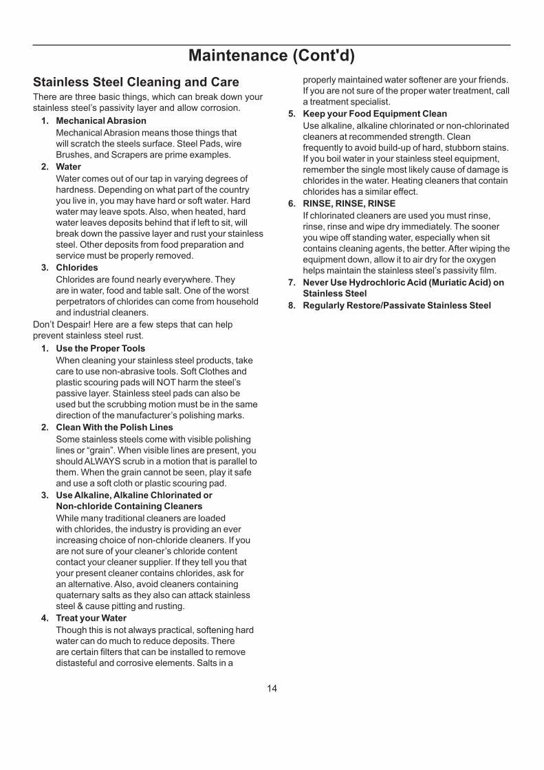
Stainless Steel Cleaning and CareThere are three basic things, which can break down your
stainless steel’s passivity layer and allow corrosion.
1. Mechanical Abrasion
Mechanical Abrasion means those things that
will scratch the steels surface. Steel Pads, wire
Brushes, and Scrapers are prime examples.
2. Water
Water comes out of our tap in varying degrees of
hardness. Depending on what part of the country
you live in, you may have hard or soft water. Hard
water may leave spots. Also, when heated, hard
water leaves deposits behind that if left to sit, will
break down the passive layer and rust your stainless
steel. Other deposits from food preparation and
service must be properly removed.
3. Chlorides
Chlorides are found nearly everywhere. They
are in water, food and table salt. One of the worst
perpetrators of chlorides can come from household
and industrial cleaners.
Don’t Despair! Here are a few steps that can help
prevent stainless steel rust.
1. Use the Proper Tools
When cleaning your stainless steel products, take
care to use non-abrasive tools. Soft Clothes and
plastic scouring pads will NOT harm the steel’s
passive layer. Stainless steel pads can also be
used but the scrubbing motion must be in the same
direction of the manufacturer’s polishing marks.
2. Clean With the Polish Lines
Some stainless steels come with visible polishing
lines or “grain”. When visible lines are present, you
should ALWAYS scrub in a motion that is parallel to
them. When the grain cannot be seen, play it safe
and use a soft cloth or plastic scouring pad.
3. Use Alkaline, Alkaline Chlorinated or
Non-chloride Containing Cleaners
While many traditional cleaners are loaded
with chlorides, the industry is providing an ever
increasing choice of non-chloride cleaners. If you
are not sure of your cleaner’s chloride content
contact your cleaner supplier. If they tell you that
your present cleaner contains chlorides, ask for
an alternative. Also, avoid cleaners containing
quaternary salts as they also can attack stainless
steel & cause pitting and rusting.
4. Treat your Water
Though this is not always practical, softening hard
water can do much to reduce deposits. There
are certain fi lters that can be installed to remove
distasteful and corrosive elements. Salts in a
properly maintained water softener are your friends.
If you are not sure of the proper water treatment, call
a treatment specialist.
5. Keep your Food Equipment Clean
Use alkaline, alkaline chlorinated or non-chlorinated
cleaners at recommended strength. Clean
frequently to avoid build-up of hard, stubborn stains.
If you boil water in your stainless steel equipment,
remember the single most likely cause of damage is
chlorides in the water. Heating cleaners that contain
chlorides has a similar effect.
6. RINSE, RINSE, RINSE
If chlorinated cleaners are used you must rinse,
rinse, rinse and wipe dry immediately. The sooner
you wipe off standing water, especially when sit
contains cleaning agents, the better. After wiping the
equipment down, allow it to air dry for the oxygen
helps maintain the stainless steel’s passivity fi lm.
7. Never Use Hydrochloric Acid (Muriatic Acid) on
Stainless Steel
8. Regularly Restore/Passivate Stainless Steel

15
12.Wiring Diagrams Index
Q3.5-SS Q3.5-SS-10R 10' 1H84982

16
13. W
iring
Dia
gra
m
DATE:
PROJECT TITLE: DRAWING #:DRAWN BY:
PRODUCTION ORDER #: DRAWING TITLE:
DATE:Hussmann Corporation, Int'l.
13770 Ramona Avenue
Chino, CA. 91710
(909)-590-4910 Lic.#: 644406
REVISIONS:
#: DESCRIPTION: CHECKED BY:BY:
FILE LOCATION:
CRAIG BOOREY
PAGE OF
BL
AC
K#
14
WH
ITE
#1
4
~120 VAC - 60 Hz.
MCA= 1.5A
MOP= 15A
~120 VAC - 60 Hz.
BUNDLEBROWN
L1 N
MCA= .60A
MOP= 15A
BUNDLE
BLACK/WHITE
N L
BL
K#
14
MOP= 15A
WH
T#
14
T-STAT
225-01-0707
LIQUIDSOLENOID
225-01-3206
.14A @ 120VAC
INCOMING POWER
~120 VAC - 60 Hz
15.0L1
120 V
LOADING
GFCIDUPLEX
125-01-3178
NOTE FOR GFCI PROTECTION: IF MORE THAN ONESINGLE RECEPTACLE IS USED IN CONJUNCTION WITHA GFCI DUPLEX RECEPTACLE "DOWNSTREAM" ONTHE LOAD SIDE, THE SUM OF ALL RECEPTACLESSHOULD NOT BE MORE THAN 15A
LOAD SIDE POWER
RECEPTACLE125-01-0443(OPTIONAL)
~120 VAC - 60 Hz
CIRCUIT # 2 (optional)
BLK
#1
4
WH
T#
14
GR
N#
14
BUNDLEYELLOW
ALL SINGLERECEPTACLES TO BETIED TO DUPLEXGFCI RECEPTACLE
EVAPFAN MOTOR (EE)(4)04776534W .12A @ 120VAC
M M M M
LIGHT CIRCUIT= 1.19A 128W
CANOPYSHELVES
OPTIONAL
TOGGLESWITCH
125-01-0307
FUSE125-01-8604FUSE HOLDER125-01-8605
15A
RE
D+
BLU
E-
5'L.E
.D.
LIG
HT
DR
IVE
R05
188
98
BA
AB
11
00
LE
20
2
RE
D+
BLU
E-
BUNDLEORANGE
L1 N
DR
IVE
R05
18
898
BA
AB
11
00
LE
20
2
5'L.E
.D.
LIG
HT
5'L.E
.D.
LIG
HT
5'L.E
.D.
LIG
HT
5'L.E
.D.
LIG
HT
5'L.E
.D.
LIG
HT
5'L.E
.D.
LIG
HT
5'L.E
.D.
LIG
HT
1 1
3/18/13Q3.5
Q3.5-SS-10R
1H84982
A CN#696786 3/18/13 CB
NOTE: CASE MUSTBE GROUNDED
1.7L1
120 V
LOADING
CIRCUIT # 1

17
14. Troubleshooting GuideProblem Possible Cause Possible Solution
Case temperature is
too warm.
Ambient conditions may
be affecting the case
operation.
Check case position in store. Is the case located near an
open door, window, electric fan or air conditioning vent that
may cause air currents? Case must be located minimum
15 Ft away from doors or windows. Cases are designed to
operate at 55% Relative humidity and a temperature of 75°F.
Discharge air temp is out
of spec.
Check evaporator fan operation. Check electrical connections
and input voltage.
Fans are installed backwards. Check airfl ow direction.
Fan blades are installed incorrectly. Make sure fan blades
have correct pitch and are per specifi cation.
Check to see that fan plenum is installed correctly. It should
not have any gaps.
Check suction pressure and insure that it meets factory
specifi cations.
Case is in defrost. Check defrost settings. See Technical Specifi cations section.
Product load may be over
its limits blocking airfl ow.
Redistribute product so it does not exceed load level. There
is a sticker on the inside of the case indicating what the
maximum load line is.
Coil is freezing over. Return air is blocked, make sure debris is not blocking the
intake section.
Coil close-offs are not installed. Inspect coil to make sure
these parts are on the case.
Condensing coil or
evaporator coil is clogged
or dirty.
Clean coil.
Case temperature is
too cold.
The t-stat temp is set too
low.
Check settings. See Technical Specifi cations section.
Ambient conditions may
be affecting the case
operation.
Check case position in store. Is the case located near an
open door, window, electric fan or air conditioning vent that
may cause air currents? Case must be located minimum
15 Ft away from doors or windows. Cases are designed to
operate at 55% Relative humidity and a temperature of 75°F.
Condensation on
glass.
Ambient conditions may
be affecting the case
operation.
Check case position in store. Is the case located near an
open door, window, electric fan or air conditioning vent that
may cause air currents? Case must be located minimum
15 Ft away from doors or windows. Cases are designed to
operate at 55% Relative humidity and a temperature of 75°F.
Inadequate air circulation. Check if air sweep fans are functioning, check electrical
connections.
There is not enough heat
provided in the airfl ow.
Check if air sweep heater is functioning, check electrical
connections.
There are glass gaps on
the side of the case.
See glass adjustment section.
Glass is not completely
shut.
Close glass correctly.
18
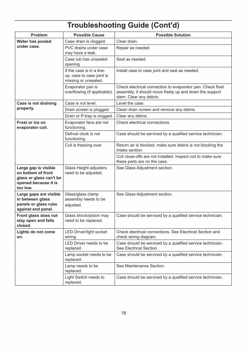
Problem Possible Cause Possible Solution
Water has pooled
under case.
Case drain is clogged. Clear drain.
PVC drains under case
may have a leak.
Repair as needed.
Case tub has unsealed
opening.
Seal as needed.
If the case is in a line-
up, case to case joint is
missing or unsealed.
Install case to case joint and seal as needed.
Evaporator pan is
overfl owing (if applicable).
Check electrical connection to evaporator pan. Check fl oat
assembly, it should move freely up and down the support
stem. Clear any debris.
Case is not draining
properly.
Case is not level. Level the case.
Drain screen is plugged. Clean drain screen and remove any debris.
Drain or P-trap is clogged. Clear any debris.
Frost or ice on
evaporator coil.
Evaporator fans are not
functioning.
Check electrical connections.
Defrost clock is not
functioning.
Case should be serviced by a qualifi ed service technician.
Coil is freezing over. Return air is blocked, make sure debris is not blocking the
intake section.
Coil close-offs are not installed. Inspect coil to make sure
these parts are on the case.
Large gap is visible
on bottom of front
glass or glass can't be
opened because it is
too low.
Glass Height adjusters
need to be adjusted.
See Glass Adjustment section.
Large gaps are visible
in between glass
panels or glass rubs
against end panel.
Glass/glass clamp
assembly needs to be
adjusted.
See Glass Adjustment section.
Front glass does not
stay open and falls
closed.
Glass shock/piston may
need to be replaced.
Case should be serviced by a qualifi ed service technician.
Lights do not come
on.
LED Driver/light socket
wiring.
Check electrical connections. See Electrical Section and
check wiring diagram.
LED Driver needs to be
replaced.
Case should be serviced by a qualifi ed service technician.
See Electrical Section.
Lamp socket needs to be
replaced.
Case should be serviced by a qualifi ed service technician.
Lamp needs to be
replaced.
See Maintenance Section.
Light Switch needs to
replaced.
Case should be serviced by a qualifi ed service technician.
Troubleshooting Guide (Cont'd)
19
1.2 Refrigeration piping should be sized according to
the equipment manufacturer’s recommendations
and installed in accordance with normal
refrigeration practices. Refrigeration piping
should be insulated according to Hussmann’s
recommendations.
1.3 A clogged waste outlet blocks refrigeration. The
installer is responsible for the proper installation
of the system which dispenses condensate waste
through an air gap into the building indirect waste
system.
1.4 The installer should perform a complete start-up
evaluation prior to the loading of food into the
refrigerator, which includes such items as:
a) Initial temperature performance, Coils should
be properly fed with a refrigerant according to
manufacturer’s recommendations.
b) Observation of outside infl uences such as
drafts, radiant heating from the ceiling and
from lamps. Such infl uence should be properly
corrected or compensated for.
c) At the same time, checks should be made of
the store dry-bulb and wet-bulb temperatures
to ascertain that they are within the limits
prescribed by Hussmann.
d) Complete start-up procedures should include
checking through a defrost to make certain
of its adequate frequency and length without
substantially exceeding the actual needs.
This should include checking the electrical
or refrigerant circuits to make sure that
defrosts are correctly programmed for all the
refrigerators connected to each refrigeration
system.
e) Recording instruments should be used to
check performance.
Appendix C. - Field
Recommendations
Recommendations for fi eld evaluating the performance
of retail food refrigerators and hot cases
1.0 The most consistent indicator of display refrigerator
performance is temperature of the air entering the
product zone (see Appendix A). In practical use,
the precise determination of return air temperature
is extremely diffi cult. Readings of return air
temperatures will be variable and results will be
inconsistent. The product temperature alone is not
an indicator of refrigerator performance.
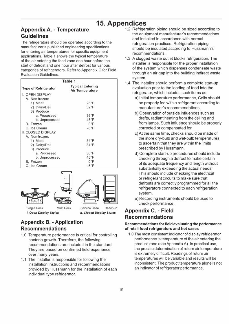
Appendix A. - Temperature
GuidelinesThe refrigerators should be operated according to the
manufacturer’s published engineering specifi cations
for entering air temperatures for specifi c equipment
applications. Table 1 shows the typical temperature
of the air entering the food zone one hour before the
start of defrost and one hour after defrost for various
categories of refrigerators. Refer to Appendix C for Field
Evaluation Guidelines.
Table 1
Type of RefrigeratorTypical Entering
Air Temperature
I. OPEN DISPLAY
A. Non frozen:
1) Meat 28°F
2) Dairy/Deli 32°F
3) Produce
a. Processed 36°F
b. Unprocessed 45°F
B. Frozen 0°F
C. Ice Cream -5°F
II.CLOSED DISPLAY
A. Non frozen:
1) Meat 34°F
2) Dairy/Deli 34°F
3) Produce
a. Processed 36°F
b. Unprocessed 45°F
B. Frozen 0°F
C. Ice Cream -5°F
Single Deck Multi Deck Service Case Reach-In
I. Open Display Styles II. Closed Display Styles
Appendix B. - Application
Recommendations1.0 Temperature performance is critical for controlling
bacteria growth. Therefore, the following
recommendations are included in the standard
They are based on confi rmed fi eld experience
over many years.
1.1 The installer is responsible for following the
installation instructions and recommendations
provided by Hussmann for the installation of each
individual type refrigerator.
15. Appendices
20
NOTE: Public Health will use the temperature of the product in
determining if the refrigerator will be allowed to display
potentially hazardous food. For the purpose of this
evaluation, product temperature above the FDA Food
Code 1993 temperature for potentially hazardous food
will be the fi rst indication that an evaluation should
be performed. It is expected that all refrigerators will
keep food at the FDA Food Code 1993 temperature for
potentially hazardous food.
1.1 The following recommendations are made
for the purpose of arriving at easily taken and
understood data which, coupled with other
observations, may be used to determine whether
a display refrigerator is working as intended:
a) INSTRUMENT - A stainless steel stem-type
thermometer is recommended and it should
have a dial a minimum of 1 inch internal
diameter. A test thermometer scaled only
in Celsius or dually scaled in Celsius and
Fahrenheit shall be accurate to 1°C (1.8°F).
Temperature measuring devices that are
scaled only in Fahrenheit shall be accurate to
2°F. The thermometer should be checked for
proper calibration. (It should read 32°F when
the stem is immersed in an ice water bath).
b) LOCATION - The probe or sensing element
of the thermometer should be located in
the airstream where the air fi rst enters the
display or storage area, and not more than 1
inch away from the surface and in the center
of the discharge opening.
c) READING - It should fi rst be determined
that the refrigerator is refrigerating and has
operated at least one hour since the end
of the last defrost period. The thermometer
reading should be made only after it has
been allowed to stabilize, i.e., maintain a
constant reading.
d) OTHER OBSERVATIONS - Other
observations should be made which may
indicate operating problems, such as
unsatisfactory product, feel/appearance.
e) CONCLUSIONS - In the absence of any
apparent undesirable conditions, the
refrigerator should be judged to be operating
properly. If it is determined that such
condition is undesirable, i.e., the product is
above proper temperature, checks should be
made for the following:1. Has the refrigerator been loaded with warm
product?
2. Is the product loaded beyond the “Safe Load Line”
markers?
3. Are the return air ducts blocked?
4. Are the entering air ducts blocked?
5. Is a dumped display causing turbulent air fl ow and
mixing with room air?
6. Are spotlights or other high intensity lighting directed
onto the product?
7. Are there unusual draft conditions (from heating/air-
conditioning ducts, open doors, etc.)?
8. Is there exposure to direct sunlight?
9. Are display signs blocking or diverting airfl ow?
10. Are the coils of the refrigerator iced up?
11. Is the store ambient over 75°F, 55% RH as set forth
in ASHRAE Standard 72 and ASHRAE Standard
117?
12. Are the shelf positions, number, and size other than
recommended by Hussmann?
13. Is there an improper application or control system?
14. Is the evaporator fan motor/blade inoperative?
15. Is the defrost time excessive?
16. Is the defrost termination, thermostat (if used) set
too high?
17. Are the refrigerant controls incorrectly adjusted?
18. Is the air entering the condenser above design
conditions? Are the condenser fi ns clear of dirt, dust,
etc.?
19. Is there a shortage of refrigerant?
20. Has the equipment been modifi ed to use
replacements for CFC-12, CFC-502 or other
refrigerant? If so, have the modifi cations been
made in accordance with the recommendations of
the equipment manufacturer? Is the refrigerator
charged with the proper refrigerant and lubricant?
Does the system use the recommended
compressor?
Appendix D. - Recommendations to
User1.0 Hussmann Corporation provides instructions
and recommendations for proper periodic
cleaning. The user will be responsible for
such cleaning, including the cleaning of low
temperature equipment within the compartment
and the cooling coil area(s). Cleaning practices,
particularly with respect to proper refrigerator
unloading and warm-up, must be in accordance
with applicable recommendations.
Appendices (Cont'd)
21
1.1 Cleaning of non frozen food equipment should
include a weekly cleaning of the food compartment
as a minimum to prevent bacteria growth from
accumulating. Actual use and products may dictate
more frequent cleaning. Circumstances of use and
equipment design must also dictate the frequency
of cleaning the display areas. Weekly washing down
of the storage compartment is also recommended,
especially for equipment subject to drippage of milk
or other liquids, or the collection of vegetable, meat,
crumbs, etc. or other debris or litter. Daily cleaning
of the external areas surrounding the storage or
display compartments with detergent and water will
keep the equipment presentable and prevent grime
buildup.
1.2 Load levels as defi ned by the manufacturer must be
observed.
1.3 The best preservation is achieved by following
these rules:
a) Buy quality products.
b) Receive perishables from transit equipment
at the ideal temperature for the particular
product.
c) Expedite perishables to the store’s storage
equipment to avoid unnecessary warm-up
and prolonged temperature recovery. Food
store refrigerators are not food chillers nor
can they reclaim quality lost through previous
mishandling.
d) Care must be taken when cross
merchandising products to ensure that
potentially hazardous vegetable products are
not placed in non refrigerated areas.
e) Display and storage equipment doors should
be kept closed during periods of inactivity.
f) Minimize the transfer time of perishables from
storage to display.
g) Keep meat under refrigeration in meat cutting
and processing area except for the few
moments it is being handled in processing.
When a cut or tray of meat is not to be worked
on immediately, the procedure should call for
returning it to refrigeration.
h) Keep tools clean and sanitized. Since
mechanical equipment is used for fresh meat
processing, all such equipment should be
cleaned at least daily and each time a different
kind of meat product comes in contact with the
tool or equipment.
i) Make sure that all refrigeration equipment is
installed and adjusted in strict accordance with
the manufacturer’s recommendations.
j) See that all storage and refrigeration
equipment is kept in proper working order by
routine maintenance.
For further technical information, please log on to http://www.hussmann.com/products/Q3.5-SS.htm
Appendices (Cont'd)
22
The MODEL NAME and SERIAL NUMBER is required in order to provide
you with the correct parts and information for your particular unit.
They can be found on a small metal plate on the unit.
Please note them below for future reference.
MODEL:
SERIAL NUMBER:
/ChinoAdditional copies of this publication may be obtained by contacting:
Hussmann® Chino
13770 Ramona Avenue • Chino, California 91710
(909) 628-8942 FAX
(909) 590-4910
(800) 395-9229
Service Record
Last service date: By:
_______________ __________________________________________________________________________________________________
_______________ __________________________________________________________________________________________________
_______________ __________________________________________________________________________________________________
_______________ __________________________________________________________________________________________________
_______________ __________________________________________________________________________________________________
_______________ __________________________________________________________________________________________________
_______________ __________________________________________________________________________________________________


