
CENTRAL PARK – WILTON B CONDUCTOR RELACEMENT
Attachment A
CONDITION ASSESSMENT

Central Park – Wilton B Conductor Replacement – Condition Assessment © Transpower New Zealand Ltd 2013 Page 2 of 14
1| Executive Summary
The Central Park – Wilton B (CPK-WIL B) line is presently strung with duplex Zebra conductor
for all but the final 5 spans into the Central Park substation which is strung with a simplex
Chukar conductor. This line is in a highly corrosive environment with a lot of air borne salts due
to the close proximity to the coast.
Conductor condition assessment has shown that the Zebra section of the line has reached
replacement criteria and requires replacement. The Chukar section of the line has also been
assessed, but due to the different structure of this conductor, it has performed better than the
Zebra in the corrosive environment. It is estimated that the Chukar has 10 years remaining life
and should be scheduled for replacement in the later stage of RCP3.
Experience from previous testing and inspections has established that a Zebra ACSR/GZ
conductor of this era has an estimated life of 40 years in a highly corrosive environment. The
CPK-WIL B line was commissioned in 1978 and therefore the conductor has performed as
expected based on previous experience.
Until the Zebra conductor is completely replaced, on-going repairs and inspections will be
required to ensure the risk of a conductor failure is appropriately managed. This is likely to be
in the form of isolated conductor defect removal and close aerial inspections.
Central Park – Wilton B Conductor Replacement – Condition Assessment © Transpower New Zealand Ltd 2013 Page 3 of 14
2| Introduction
This document is a Condition Assessment report for the Central Park – Wilton B line conductor replacement listed project application.
2.1 Purpose
The purpose of this document is to outline condition assessment information which has led to the need to replace the conductor on the Central Park – Wilton B line.
2.2 Document Structure
This report forms part of the Central Park – Wilton B line conductor replacement listed project application.
Central Park – Wilton B Conductor Replacement – Condition Assessment © Transpower New Zealand Ltd 2013 Page 4 of 14
3| Condition Assessment
3.1 Why does the conductor need to be replaced? The main reasons for this conductor reaching end of life are as follows:
1. Widespread corrosion of the steel core wire and aluminium strands due to ‘grease
holidays’; (sections that did not receive grease during manufacture); and
2. Dog bone spacer damage due to the design of some original conductor spacers
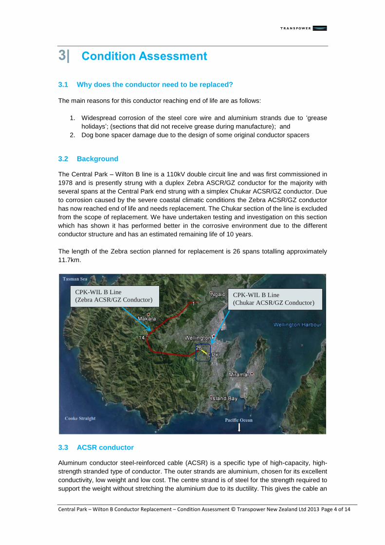
3.2 Background The Central Park – Wilton B line is a 110kV double circuit line and was first commissioned in
1978 and is presently strung with a duplex Zebra ASCR/GZ conductor for the majority with
several spans at the Central Park end strung with a simplex Chukar ACSR/GZ conductor. Due
to corrosion caused by the severe coastal climatic conditions the Zebra ACSR/GZ conductor
has now reached end of life and needs replacement. The Chukar section of the line is excluded
from the scope of replacement. We have undertaken testing and investigation on this section
which has shown it has performed better in the corrosive environment due to the different
conductor structure and has an estimated remaining life of 10 years.
The length of the Zebra section planned for replacement is 26 spans totalling approximately
11.7km.
3.3 ACSR conductor Aluminum conductor steel-reinforced cable (ACSR) is a specific type of high-capacity, high-
strength stranded type of conductor. The outer strands are aluminium, chosen for its excellent
conductivity, low weight and low cost. The centre strand is of steel for the strength required to
support the weight without stretching the aluminium due to its ductility. This gives the cable an
CPK-WIL B Line
(Zebra ACSR/GZ Conductor) CPK-WIL B Line
(Chukar ACSR/GZ Conductor)

Central Park – Wilton B Conductor Replacement – Condition Assessment © Transpower New Zealand Ltd 2013 Page 5 of 14
overall high tensile strength. The tensile capacity of ACSR conductor is calculated by combining
the relative strengths of the aluminium strands and the steel core wire. In the case of Zebra
ASCR conductor, with 54 aluminium strands and 7 steel strands, the aluminium strands
contribute approximately 50% of the strength (~1% per strand) and the steel the remaining
50%. Extensive study has now found that ACSR/GZ conductors are prone to accelerated
corrosion in salt laden areas as the galvanic cells are formed due to the dissimilar metals (steel,
zinc and aluminium). The addition of grease between the zinc and aluminium creates a
protective barrier against this.
Once the galvanised coating of the steel core has galvanically corroded it is found that the steel
core wire does not corrode appreciably because the aluminium strands “sacrifice” themselves
to protect the steel. Loss of strength therefore occurs from loss of aluminium section – noted
by visible aluminium oxide build up, and in the worst case, bulging of the conductor. From
previous conductor bulge analysis on ACSR conductor we can get an indicative estimate of the
loss of aluminium section from the bulge diameter.
Significant corrosion of the aluminium strands leads to a loss of the conductive cross sectional
area as well as pitting of the steel core wire. Under electrical load the reduced area leads to
an increase in temperature of the aluminium, which in turn accelerates the corrosion process.
Conductor failure is typically caused by the steel core wire overheating and effectively burning
down, or when exposed to high load conditions that exceed the remaining strength of the
conductor.
Today’s modern equivalent conductor is greased ACSR/AC – an ACSR conductor with an
aluminium clad core wire. The advantage of an aluminium clad core is that it removes the
galvanic cell between the previously used galvanised core (zinc) and the dissimilar aluminium
strands. In addition, in areas of high corrosion Transpower now specifies a Type 2 greasing to
IEC 61089 (greasing to the outer layer of the conductor). The figurei below shows the expected
conductor life for the different conductors and corrosion zones in New Zealand.
Figure 1 - Expected conductor life for different conductors in different corrosion zones
3.4 Failure modes
As seen in the figure above, the expected life of ACSR/GZ Grease Holiday (GZ meaning
galvanised core) conductors in salt-laden environments as used in the 1980s is approximately
40 years. The points of failure being identified today are predominantly where grease has not
been applied, or missed, during the manufacturing process, known as ‘grease holidays’ or at
Central Park – Wilton B Conductor Replacement – Condition Assessment © Transpower New Zealand Ltd 2013 Page 6 of 14
points known as dog bone spacer damage. The following extracts from the conductor fleet
strategy TP.FL 01.00i give more detail on these corrosion mechanisms.
Grease holiday corrosion: As discussed in subsection 2.1.3 above, grease applied
to the core wire during manufacture provides a barrier to galvanic corrosion and can
significantly extend conductor life. However, if it is applied poorly it is of little or even
negative benefit. Experience has shown that grease application was poorly managed
for conductors on many lines throughout the country, resulting in sections of core
wire where no grease was applied at all (‘grease holidays’). Grease holidays expose
small localised areas of the core wire to the environment that results in higher than
normal corrosion rates. In 2005, a span on the BPE-HAY A line failed due to corrosion
after only 25 years in service.
Dog bone spacer corrosion: A number of lines in the network with twin bundled
conductors have external corrosion damage from early ‘dog bone’ spacers. This
corrosion occurred through the late 1980s to early 1990s as a result of incompatible
rubber in contact with the conductor. The majority of damage is confined to the
outer layer of the conductor. Preform rods have been applied as a permanent repair.
Sampling and metallurgical assessment suggest the corrosion mechanism is relatively
benign now that the incompatible rubber has been removed. Some lines in more
coastal areas require implosive repair sleeves to be fitted, as damage is beyond the
repair capabilities of the pre-form rods.
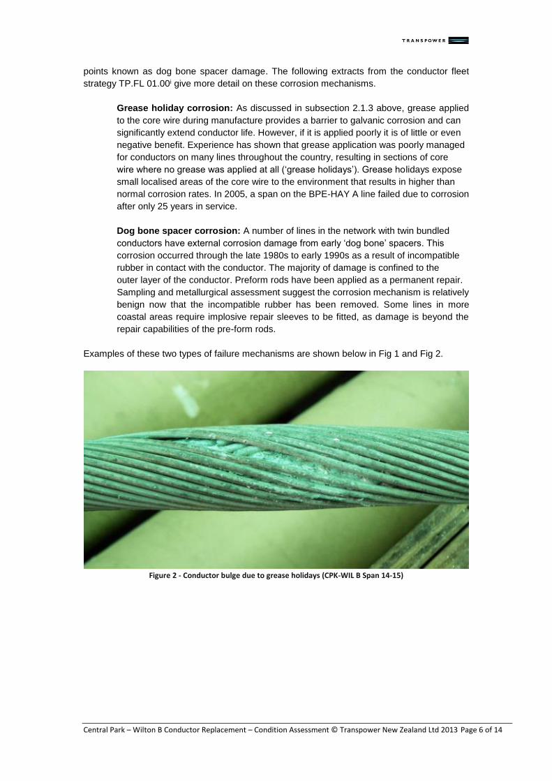
Examples of these two types of failure mechanisms are shown below in Fig 1 and Fig 2.
Figure 2 - Conductor bulge due to grease holidays (CPK-WIL B Span 14-15)

Central Park – Wilton B Conductor Replacement – Condition Assessment © Transpower New Zealand Ltd 2013 Page 7 of 14
Figure 3 - Example of dog done spacer damage as seen on the BPE-WIL A line
Recent conductor failures on other lines strung with similar conductor has greatly improved the
knowledge and awareness of these failure mechanisms. The main cause is identified as
corrosion of the aluminium strands and steel core wire, with the steel strands yielding under
electrical load (burn-down). As noted, bulging occurs when galvanising on the steel core wire
is depleted and the aluminium strands corrode, forming white aluminium oxide which expands
within the conductor.
Experience has shown that once a conductor bulge is first detected there is approximately two
years of operation remaining before that section of conductor needs to be repaired or replaced.
Once bulging occurs there is also an inherent risk with this timeframe as factors such as
location, degradation rate and line load need to be also considered, i.e. the rate of degradation
is not typically linear, and can differ for different sections of the same line.
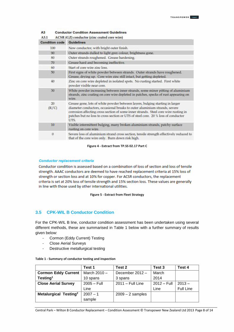
3.4.1 Replacement Criteria When assessing the condition of in service conductors all assessment is undertaken in
accordance with the condition assessment service specification TP.SS 02.17 - Part Cii. This
service specification ensures that all conductors throughout the country are assessed against
a common standard giving comparable and repeatable results. Figure 4 shows the coding
system that is used for ACSR/GZ conductor. This replacement criteria is also reiterated in the
fleet strategy, as shown in Figure 5.
The replacement criteria level chosen ensure there is a correlation between the maximum
allowable design loads and the residual strength in the conductor. The Transpower loading
code TP.DL 12.01iii gives the maximum allowable design loads for the conductor. The actual
maximum utilisation of a span of conductor is highly dependant on many factors such as span
length, elevation and location and as such this is also considered when determining the
appropriate time to replace conductor.
Central Park – Wilton B Conductor Replacement – Condition Assessment © Transpower New Zealand Ltd 2013 Page 8 of 14
Figure 4 - Extract from TP.SS 02.17 Part C
Figure 5 - Extract from Fleet Strategy
3.5 CPK-WIL B Conductor Condition
For the CPK-WIL B line, conductor condition assessment has been undertaken using several
different methods, these are summarised in Table 1 below with a further summary of results
given below:
- Cormon (Eddy Current) Testing
- Close Aerial Surveys
- Destructive metallurgical testing
Table 1 - Summary of conductor testing and inspection
Test 1 Test 2 Test 3 Test 4
Cormon Eddy Current
Testing1
March 2010 –
10 spans
December 2012 –
3 spans
March
2014
Close Aerial Survey 2005 – Full
Line
2011 – Full Line 2012 – Full
Line
2013 –
Full Line
Metalurgical Testing2 2007 – 1
sample
2009 – 2 samples
Central Park – Wilton B Conductor Replacement – Condition Assessment © Transpower New Zealand Ltd 2013 Page 9 of 14
1Only the results for the Zebra conductor section are reported on in this report. 2In addition to the testing specifically undertaken on the CPK-WIL B line, 3 samples were also
taken from the BPE-WIL A line, which has the same conductor, to investigate Dog Bone spacer
damage. This line is in the same relative location as the CPK-WIL B line and as such these
results are relevant to this line.
3.5.1 Cormon Testing Summary The Cormon detector is a non-destructive test device that uses eddy current technology to
estimate the remaining thickness of zinc or aluminium coating on the steel core wire of ACSR
conductors. The Cormon detector is placed on the conductor by linemen span by span. The
device then self-propels to the other end of the span, taking measurements every 5mm to
10mm. Results from this device have proven to be remarkably accurate, providing an excellent
indication of conductor condition without the need for destructive sample testing. We have
carried out a Cormon test programme annually since 2006. Some 1,200 sub conductor spans
had been tested by February 2013. Although some catch-up was required initially, the
programme is now at a stage where it can follow a prioritised listing of assets based on their
predicted end of life. Our strategy is to begin Cormon testing some 10 years before predicted
end of life, and then establish appropriate times for repeat inspections to ensure end of life
predictions are refined as they approachi.
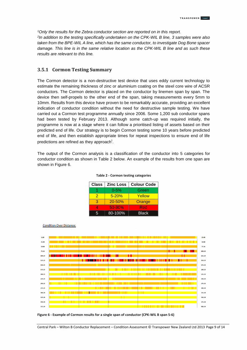
The output of the Cormon analysis is a classification of the conductor into 5 categories for
conductor condition as shown in Table 2 below. An example of the results from one span are
shown in Figure 6.
Table 2 - Cormon testing categories
Class Zinc Loss Colour Code
1 0-5% Green
2 5-20% Yellow
3 20-50% Orange
4 50-80% Red
5 80-100% Black
Figure 6 - Example of Cormon results for a single span of conductor (CPK-WIL B span 5-6)

Central Park – Wilton B Conductor Replacement – Condition Assessment © Transpower New Zealand Ltd 2013Page 10 of 14
Figure 4 shows that majority of this span is showing moderate to severe loss of its galvanising
on the steel core wire, with some isolated sections reporting no remaining glavanising. These
areas with no galavanising remaining are where the Aluminium conductor strands will begin to
sacrifice themselves and cross sectional loss will be occurring.
Overall a total of 36 spans of Zebra conductor have been Cormon tested. This represents
approximately 12% of the line which is considered a representative sample size for this line
section. A summary of these results are given below in Table 3 along with an extrapolation for
the entire line.
Table 3 - Summary of the Cormon Results for the Zebra conductor on the CPK-WIL B line
Section WIL-26 (Zebra) Predicted Zinc Loss (No. of defects)
No of conductor spans
Total spans with corrosion defects
Class 1 0-5%
Class 2 5-20%
Class 3 20-50%
Class 4 50-80%
Class 5 80-100%
Tested Spans
36 24 0 3 9 8 16
Extrapolated results
(whole line) 312 208 0 26 78 69 139
Percentage of entire line 67% 0% 8% 25% 22% 44%
Margin of error 13% 0% 8% 12% 11% 14%
These cormon results indicate the overall condition of the conductor on this line is very poor
with approximately 44% of the spans showing signs of complete galvanising loss on the steel
core wire. These spans can all be expected to show visible signs of bugling and loss of
aluminium cross section in the next few years as the aluminium strands begin to sacrifice now
that the galvanising is all gone from the steel core wire. The conductor should be replaced prior
to this widespread corrosion and breakdown being evident, more on this is discussed in section
3.5.2 below.
Due to the limited sample size there is a relatively high margin of error for these extrapolated
results. Based on the sample size of 36 and a 90% confidence interval (z* = 1.645) the
approximate margin of error for each extrapolation is given in Table 3 above. Due to the nature
of condition assessment where a small population spans are randomly selected it is unlikely
that we have assessed the worst span on the asset, conversely it is also unlikely we have
assessed the best span.
3.5.2 Close Aerial Survey Summary Using a helicopter to undertake a close aerial survey is considered the best method of
identifying conductor bulges/defects or areas requiring further monitoring known as “markers”.
A conductor bulge or defect is characterised by a noticeable bulge in the conductor and these
correspond to a CA score of 20 or less depending on the diameter of the bulge. A marker is an
area of conductor that is showing discoloration but no visible bulging occurring yet. These
markers can be re evaluated during subsequent inspections and are generally good indicators
of immenent conductor bulging.

Central Park – Wilton B Conductor Replacement – Condition Assessment © Transpower New Zealand Ltd 2013Page 11 of 14
To date, 2 close aerial surveys have been undertaken on the CPK-WIL B line in 2011 and 2013.
The summary results of this are shown below:
2005 Result: The first bulge on this line was discovered in span 1-2. 2011 Result:
- Spans 0001 – 0030 were flown. - 2 defects less than code 20 found.
2012 Result: As part of the handover to the new maintenance contractor this line was reflown in 2012. These
survey re-evaluated the code 18 defect (from 2011) to code 21 and the other defect could not
be seen. The results of aerieal surveys are highly dependant on the light and weather conditions
on the day, and as such it can be very difficult to locate some of the smaller bulges.
2013 Result:
- Spans 0001 – 0030 were flown. - 110 markers in the range CA21-25 - 1 code 20 defect found. - 19 defects less than code 20 found.
The increase in the number of defects found, and more importantly markers, clearly
demonstrates that the conductor on this line is reaching end of life. Given the relatively severe
environment of this line, once a conductor bulge is evident during aerial survey that section of
conductor has 2-3 years of service life remaining.
3.5.3 Destructive metallurgical testing 2005 Test – 3 Samples: Three samples were removed from the BPE-WIL A line to investigate the effects of dog bone
spacer damage. This line is strung with the same conductor from the same era and environment
as they CPK-WIL B line so these results should be applicable to the line in question.
This report found that the 3 samples tested all met or exceeded Transpowers replacement
criteria for loss of aluminium cross section. The recommendation from this report was that the
useful life of these conductors could be extended by approximately 15 years providing the
appropriate repair method is used. Further detail on these repairs is given below in section
3.5.4.
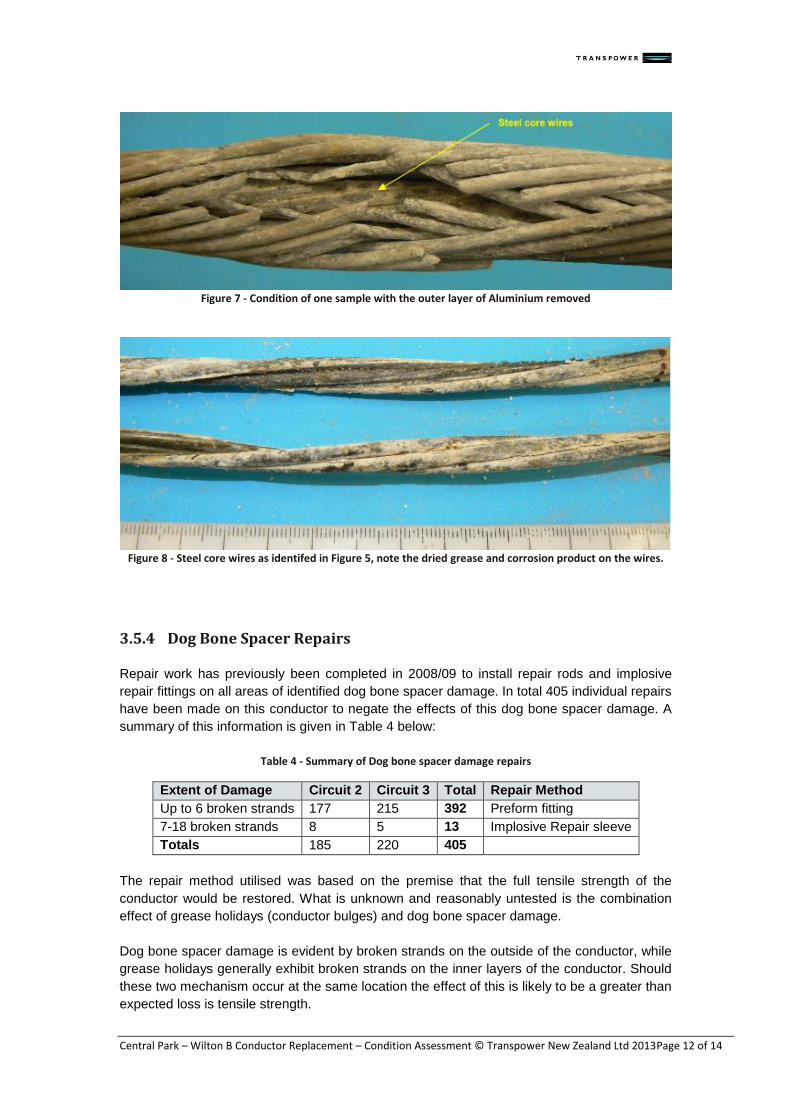
2007 Test – 1 Sample: Sample selected at random and had no visible corrosion or localised defects. Overall loss of
Aluminium was estimated at 1.93% and estimated remaining life of approximately 20 years.
2009 Test – 2 Samples: Two samples where removed as part of localised corrosion repairs where there were signs of
visible bulging. Loss of Aluminium cross section was estimated as 17.1% and 31.2%
respectively which both exceed replacement criteria of 15% loss of Aluminium.
The sample with 32.1% loss of section was estmimated to have reached the 15% replacement
criteria approximately 7 years earlier.
Figures 5 and 6 below show the condition of the on the samples at differing stages of the examination.
Central Park – Wilton B Conductor Replacement – Condition Assessment © Transpower New Zealand Ltd 2013Page 12 of 14
Figure 7 - Condition of one sample with the outer layer of Aluminium removed
Figure 8 - Steel core wires as identifed in Figure 5, note the dried grease and corrosion product on the wires.
3.5.4 Dog Bone Spacer Repairs Repair work has previously been completed in 2008/09 to install repair rods and implosive
repair fittings on all areas of identified dog bone spacer damage. In total 405 individual repairs
have been made on this conductor to negate the effects of this dog bone spacer damage. A
summary of this information is given in Table 4 below:
Table 4 - Summary of Dog bone spacer damage repairs
Extent of Damage Circuit 2 Circuit 3 Total Repair Method
Up to 6 broken strands 177 215 392 Preform fitting
7-18 broken strands 8 5 13 Implosive Repair sleeve
Totals 185 220 405
The repair method utilised was based on the premise that the full tensile strength of the
conductor would be restored. What is unknown and reasonably untested is the combination
effect of grease holidays (conductor bulges) and dog bone spacer damage.
Dog bone spacer damage is evident by broken strands on the outside of the conductor, while
grease holidays generally exhibit broken strands on the inner layers of the conductor. Should
these two mechanism occur at the same location the effect of this is likely to be a greater than
expected loss is tensile strength.
Central Park – Wilton B Conductor Replacement – Condition Assessment © Transpower New Zealand Ltd 2013Page 13 of 14
3.6 Conductor Management Options
To help manage the condition of the conductor on this asset, localised repairs have been, and
will continue to be completed on some of these defects to help ensure the condition of the entire
conductor is degraded to the point where it justifies complete replacement. The cost of this
localised repairs on this asset are far higher than might be seen on other lines due to the line
location and configuration. Depending on the location within the span and the particular span
requiring repair, crane access may not be possible and the cost to cut out these defects and
add in a new section of conductor is expected to be $100K-$200K per repair. It is therefore not
considered a long term solution to manage the numerous number of defects that are now
present on this line.
Further close aerial survey is also planned to ensure all known defects and markers are
monitored and addressed as needed to ensure the risk of a conductor drop is minimised until
the conductor is replaced.
Something else to consider is when replacing the conductor on this asset, the preferred
construction method is to use the existing conductor as a “pull wire” to string the new conductor.
To utilise this method it is also imperative that the old conductor has sufficient strength to
complete this task. If the conductor is left to the point where it cannot be used as a pull wire
then more complex and costly construction methods would need to be utilised.

Central Park – Wilton B Conductor Replacement – Condition Assessment © Transpower New Zealand Ltd 2013Page 14 of 14
4| Conclusions
The Zebra conductor between Wilton and Tower 26 (11.7km) on the CPK-WIL B line meets or
exceeds replacement criteria and is recommended for complete replacement by June 2019. By
the time of replacement this conductor will be approximately 40 years old which is the expected
service life for a Zebra ACSR conductor in this high corrosion environment.
The Chukar conductor (Tower 26 to Central Park) has an estimated remaining life of 10 years.
Further testing will be undertaken on this section of the line to provide more certainty on this
timing but this replacement should be scheduled to occur in the later stages of RCP3
Conductor monitoring and repair programmes have extended the life of the conductor but a
visual survey in June 2013 has shown there are incidences of further bulging occurring.
Condition assessment is not an exact science; however, experience with both Cormon testing
and visual inspection has led to greater certainty on remaining conductor life. Our requirement
to replace the conductor by June 2019 ensures the prudent operation of core grid assets.
Repair work is likely to continue in the interim, but due to the location and configuration of this
line it is an expensive and complex task. In some instances it is not feasible to repair conductor
defects, as crane access will be impossible.
i TP.FL 01.00 TL Conductors and Insulators Fleet Strategy (Issue 1 2013) ii TP.SS 02.17 Transmission line condition assessment, Part C: Insulators and conductors iii TP.DL 12.01 Transmission line loadings code


