Download - Chap 5 (Small Scale Fading)
1
Mobile Radio PropagationSmall-scale Path loss
Chapter 5Wireless communication
2
Small-Scale Fading and Multipath The term fading is used to describe rapid fluctuation of
the amplitude of a radio signal over a short period of time or travel distance
Fading is caused by destructive interference between two or more versions of the transmitted signal being slightly out of phase due to the different propagation time
This is also called multipath propagation
The different components are due to reflection and scattering form trees buildings and hills etc.
3
Small-Scale Fading and Multipath At a receiver the radio waves generated by same
transmitted signal may come From Different direction With Different propagation delays, With Different amplitudes With Different phases Each of the factor given above is random
The multipath components combine vectorially at the receiver and produce a fade or distortion.

4
Effects of Fading/Multipath Multipath propagation creates small-scale fading effects.
The three most important effects are:
Rapid changes in signal strength over a small travel distance or time interval;
Random frequency modulation due to varying Doppler shifts on different multipath signals; and
Time dispersion (echoes) caused by multipath propagation delays.
Even when a mobile receiver is stationary, the received signal may fade due to a non-stationary nature of the channel (reflecting objects can be moving)

5
Factors influencing small-scale fading Multipath propagation
The presence of reflecting objects and scatterers in the space between transmitter and receiver creates a constantly changing channel environment
Causes the signal at receiver to fade or distort
Speed of mobile receiver The relative motion between the transmitter and
receiver results in a random frequency modulation due to different Doppler shifts on each of the multipath signals
Doppler shift may be positive or negative depending on direction of movement of mobile
6
Factors influencing small-scale fading Speed of surrounding objects:
If the speed of surrounding objects is greater than mobile, the fading is dominated by those objects
If the surrounding objects are slower than the mobile, then their effect can be ignored
The transmission bandwidth: Depending on the relation between the signal
bandwidth and the coherence bandwidth of the channel, the signal is either distorted or faded
If the signal bandwidth is greater than coherence bandwidth it creates distortion
If the signal bandwidth is smaller than coherence bandwidth it create small scale fading

7
Some Terminologies Level Crossing Rate Average number of times per sec that the signal crosses a certain level going in positive going direction Fading Rate Number of times the signal envelop crosses middle value in positive going direction per unit time Depth of Fading Ratio of mean square value and minimum value of fading Fading Duration Time for which signal remain below a certain threshold
8
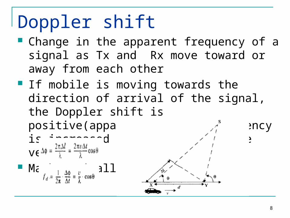
Doppler shift Change in the apparent frequency of a signal as
Tx and Rx move toward or away from each other If mobile is moving towards the direction of arrival
of the signal, the Doppler shift is positive(apparent received frequency is increased i.e. fc+fd) and vice versa
Mathematically

9
Impulse response of Multipath channel The small scale variations of a mobile radio signal
can be directly related to the impulse response of mobile radio channel.
Impulse response contains information to Simulate and Analyze the channel
The mobile radio channel can be modeled as Linear filter with time varying impulse response In case of mobile reception, the length and attenuation of various paths will change with time i.e. Channel is time varying. The time variation is strictly due to receiver
movement (t=d/v).
10
Impulse response of Multipath channel At any distance d=vt, the received signal is the combination of different signals coming with different propagation delays depending on the distance between transmitter and receiver.
So the impulse response is a function of d, which is the separation between the transmitter and receiver.
11
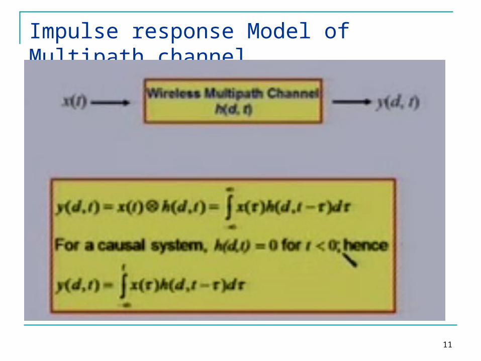
Impulse response Model of Multipath channel

12
Impulse Response Model of Multipath channel

13
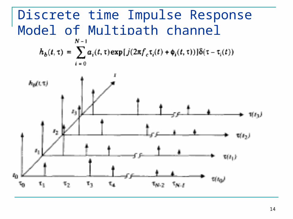
Discrete time Impulse Response Model of Multipath channel Discretize the multipath delay axis τ into equal
time delay segments called Excess Delay Bins For N such multipath components (0…N-1)
14
Discrete time Impulse Response Model of Multipath channel
15
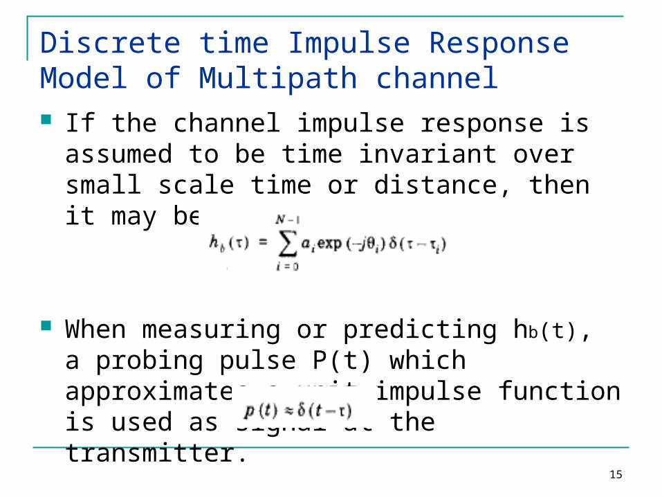
Discrete time Impulse Response Model of Multipath channel If the channel impulse response is assumed to
be time invariant over small scale time or distance, then it may be simplified as
When measuring or predicting hb(t), a probing pulse P(t) which approximates a unit impulse function is used as signal at the transmitter.
16
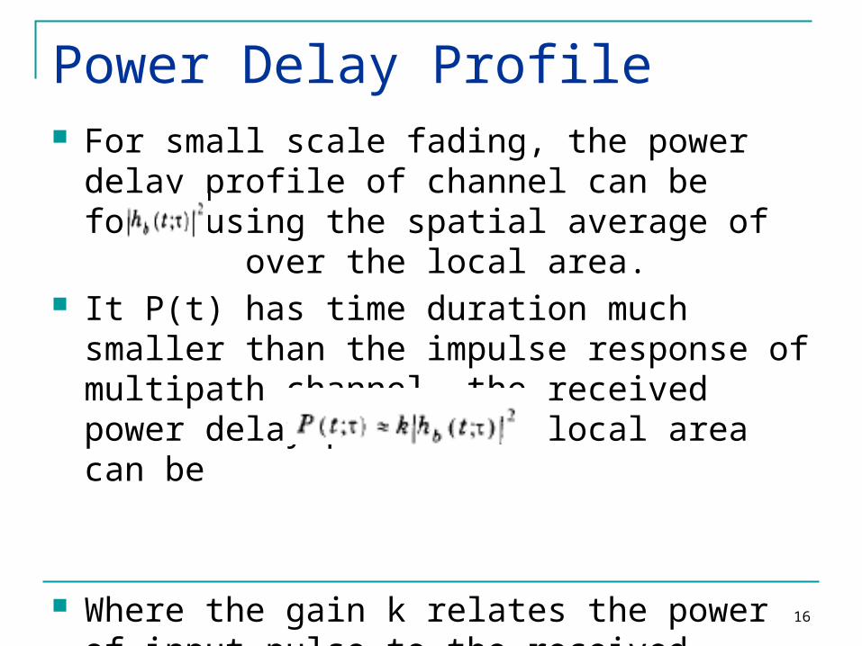
Power Delay Profile For small scale fading, the power delay profile of
channel can be found using the spatial average of over the local area.
It P(t) has time duration much smaller than the impulse response of multipath channel, the received power delay profile in local area can be
Where the gain k relates the power of input pulse to the received power.

17
Measuring PDPs Power Delay Profiles
Are measured by channel sounding techniques Plots of relative received power as a function of
excess delay They are found by averaging intantenous power
delay measurements over a local area Local area: no greater than 6m outdoor Local area: no greater than 2m indoor
Samples taken at l/4 meters approximately For 450MHz – 6 GHz frequency range.

18
Small-Scale Multipath Measurements Multipath structure is very important for small
scale fading. Several Methods
Direct RF Pulse System Spread Spectrum Sliding Correlator Channel
Sounding Frequency Domain Channel Sounding
These techniques are also called channel sounding techniques
19
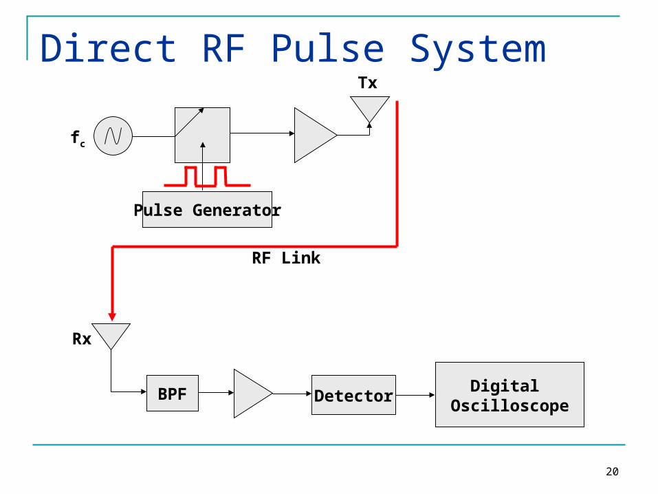
Direct RF Pulse System This method help us to determine the power
delay profile directly Objective is to find impulse response A narrow pulse is used for channel sounding. At the receiver the signal is amplified and
detected using an envelop detector. It is then stored on a high speed digital
oscilloscope. If the receiver is set on averaging mode, the
local average power delay profile is obtained
20
Direct RF Pulse System
Pulse Generator
BPF Detector Digital Oscilloscope
RF Link
fc
Tx
Rx

21
Direct RF Pulse System Problems: Subject to interference Subject to noise due to wideband pass band
filter required for multipath resolution The phases of individual multi path components
are not received due to the use of envelop detector

22
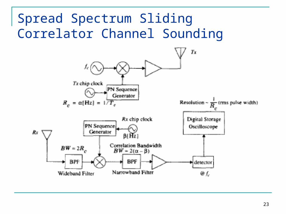
Spread Spectrum Sliding Correlator Channel Sounding
The probing signal is wide band but the receiver is narrow band
The carrier signal is spread over large bandwidth by mixing it with Pseudorandom- noise(PN) sequence having chip rate Tc.
At receiver signal is despread using same PN The transmitter chip clock rate is a little faster
then the receiver chip clock rate The result is sliding correlator. If the sequences are not maximally correlated
then the mixer will further despread the signal
23
Spread Spectrum Sliding Correlator Channel Sounding
24
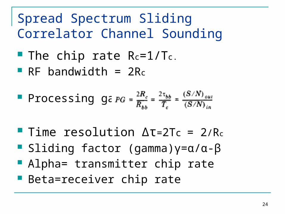
Spread Spectrum Sliding Correlator Channel Sounding The chip rate Rc=1/Tc.
RF bandwidth = 2Rc
Processing gain: :
Time resolution Δτ=2Tc = 2/Rc
Sliding factor (gamma)γ=α/α-β Alpha= transmitter chip rate Beta=receiver chip rate

25
Spread Spectrum Sliding Correlator Channel Sounding Advantages: Improves coverage range using same
transmitter power. Transmitter receiver synchronization is
eliminated using sliding correlator. Disadvantages: Measurement are not made real time The associated time required is more Phase information is lost.
26
Frequency Domain Channel Sounding Because of the dual relationship between
time and frequency it is possible to measure channel impulse response in frequency domain
A vector network analyzer is used. The S-parameter test set is used to monitor
the frequency response of the channel. The frequency sweeper scans a particular
frequency band by stepping through the discrete frequencies.

27
Frequency Domain Channel Sounding

28
Frequency Domain Channel Sounding
The number and spacing of frequency steps impact the time resolution of impulse response measurements.
The response is converted to time domain by using Inverse Discrete time Fourier Transform(IDFT)

29
Frequency Domain Channel Sounding
Disadvantages: System requires careful calibration System required hardwired synchronization
between transmitter and receiver. Practical only for indoor channel
measurements Non real time nature of measurements For time varying channels the channel
impulse response may change giving erroneous measurements
30
Parameters of Mobile Multipath Channels
Time Dispersion Parameters Grossly quantifies the multipath channel Determined from Power Delay Profile Parameters include
Mean Access Delay RMS Delay Spread Excess Delay Spread (X dB)
Coherence Bandwidth Doppler Spread and Coherence Time
31
Timer Dispersion Parameters
kk
kkk
kk
kkk
P
P
a
a
)(
))(( 2
2
22
2
22
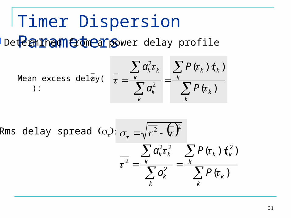
Determined from a power delay profile
Mean excess delay( ):
Rms delay spread :
kk
kkk
kk
kkk
P
P
a
a
)(
))((
2
2

32
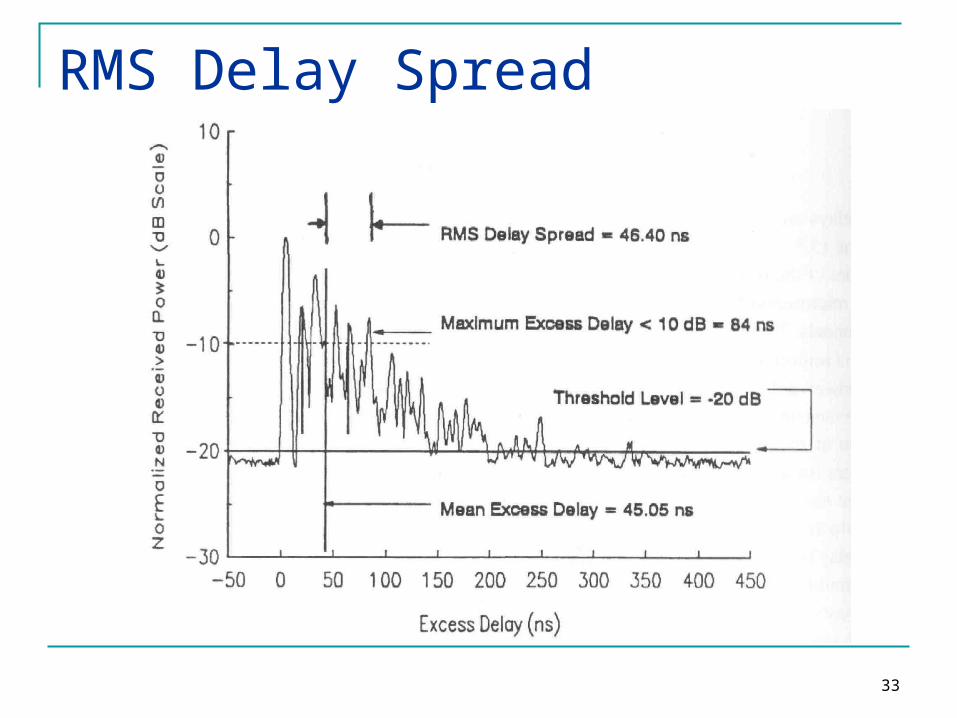
Timer Dispersion ParametersMaximum Excess Delay (X dB):
• Defined as the time delay value after which the multipath energy falls to X dB below the maximum multipath energy (not necessarily belonging to the first arriving component).
It is also called excess delay spread.
33
RMS Delay Spread
34
Noise Threshold The values of time dispersion parameters
also depend on the noise threshold (the level of power below which the signal is considered as noise).
If noise threshold is set too low, then the noise will be processed as multipath and thus causing the parameters to be higher.
35
Delay Spread, Coherence BW Describes the time dispersive nature of a channel in a local
area A received signal suffers spreading in time compared to the
transmitted signal Delay spread can range from a few hundred nanoseconds for
indoor scenario up to some microseconds in urban areas The coherence bandwidth Bc translates time dispersion into the
language of the frequency domain. It specifies the frequency range over which a channel affects
the signal spectrum nearly in the same way, causing an approximately constant attenuation and linear change in phase
The rms delay spread and coherence bandwidth are inversely proportional to each other.
36
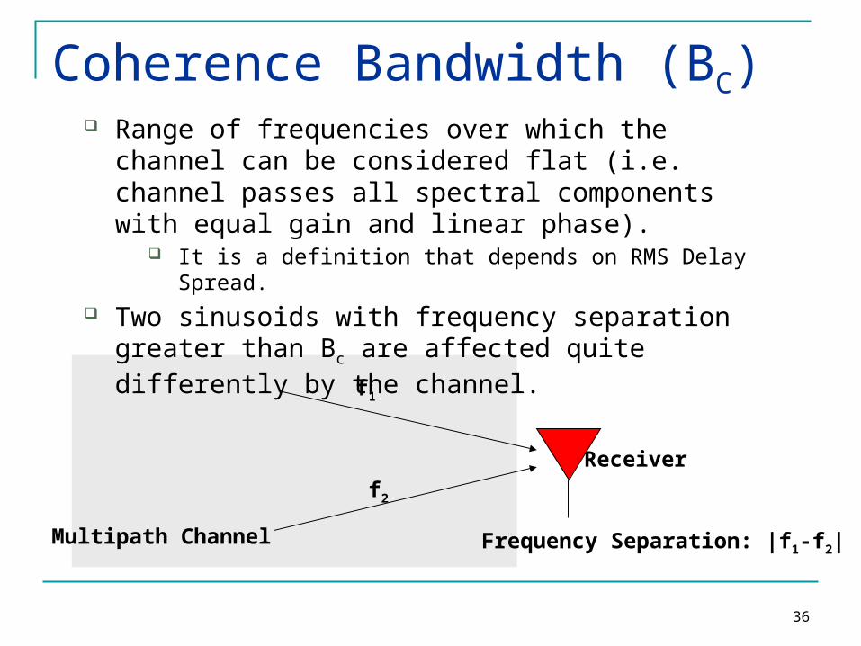
Coherence Bandwidth (BC) Range of frequencies over which the channel can be
considered flat (i.e. channel passes all spectral components with equal gain and linear phase).
It is a definition that depends on RMS Delay Spread. Two sinusoids with frequency separation greater than Bc
are affected quite differently by the channel.
Receiver
f1
f2
Multipath Channel Frequency Separation: |f1-f2|

37
Coherence Bandwidth (BC) Two frequencies that have a difference of greater
than coherence bandwidth will fade independently. Useful for diversity reception
Multiple copies of same signal are sent using different frequencies These frequencies are separated by more than coherence bandwidth of channel
Coherence bandwidth indicated the frequency selectivity during transmission
38
Coherence Bandwidth
501
CB
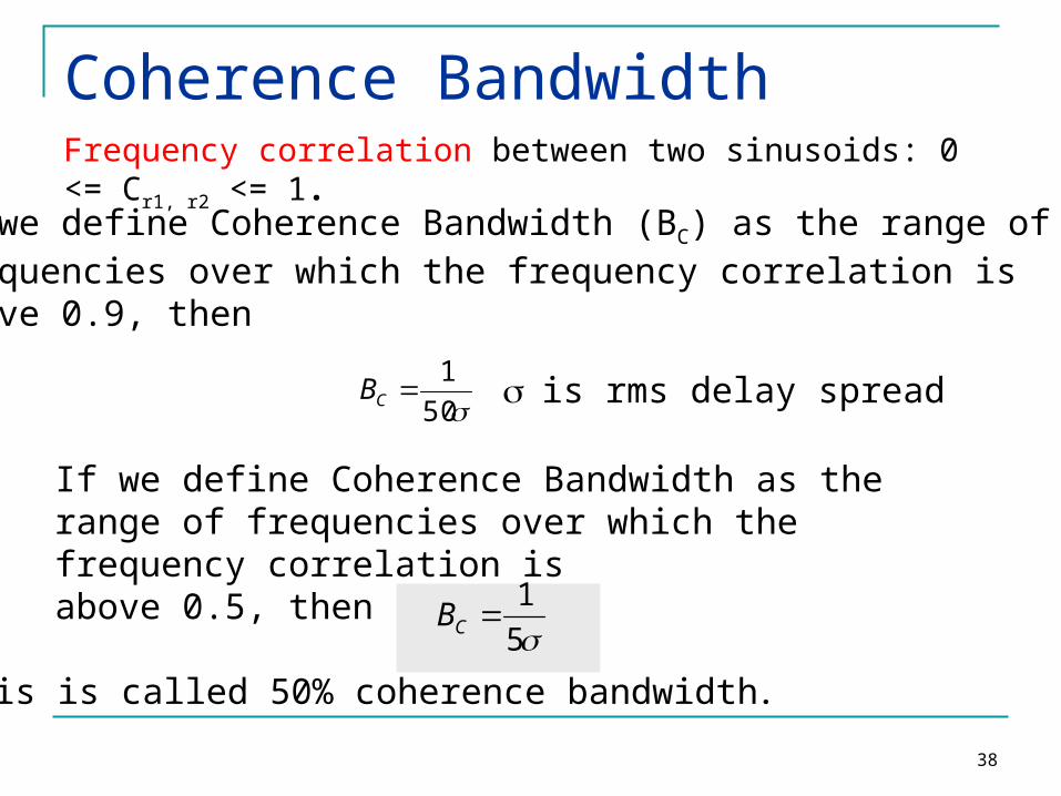
Frequency correlation between two sinusoids: 0 <= Cr1, r2 <= 1.
If we define Coherence Bandwidth (BC) as the range of frequencies over which the frequency correlation is above 0.9, then
If we define Coherence Bandwidth as the range of frequencies over which the frequency correlation is above 0.5, then
51
CB
is rms delay spread
This is called 50% coherence bandwidth.

39
Coherence Bandwidth Example:
For a multipath channel, s is given as 1.37ms. The 50% coherence bandwidth is given as: 1/5s =
146kHz. This means that, for a good transmission from a
transmitter to a receiver, the range of transmission frequency (channel bandwidth) should not exceed 146kHz, so that all frequencies in this band experience the same channel characteristics.
Equalizers are needed in order to use transmission frequencies that are separated larger than this value.
This coherence bandwidth is enough for an AMPS channel (30kHz band needed for a channel), but is not enough for a GSM channel (200kHz needed per channel).
40
Doppler Spread and Coherence time Delay spread and Coherence bandwidth describe the
time dispersive nature of the channel in a local area. They don’t offer information about the time varying nature of the channel caused by relative motion of transmitter and receiver.
Doppler Spread and Coherence time are parameters which describe the time varying nature of the channel in a small-scale region.
Time varying nature of channel caused either by relative motion between BS and mobile or by motions of objects in channel are categorized by BD and Tc
41
Doppler Spread Measure of spectral broadening caused by
motion We know how to compute Doppler shift: fd
Doppler spread, BD, is defined as the maximum Doppler shift: fm = v/l
if Tx signal bandwidth (Bs) is large such that Bs >> BD then effects of Doppler spread are NOT important so Doppler spread is only important for low bps (data rate) applications (e.g. paging), slow fading channel

42
Coherence time is the time duration over which the channel impulse response is essentially invariant. If the symbol period of the baseband signal (reciprocal of the baseband signal bandwidth) is greater the coherence time, than the signal will distort, since channel will change during the transmission of the signal .
Coherence Time
mfCT 1
Coherence time (TC) is defined as: TS
TC
Dt=t2 - t1t1 t2
f1f2

43
Coherence Time
Coherence time is also defined as:
mfC f
Tm
423.0216
9
Coherence time definition implies that two signals arriving with a time separation greater than TC are affected differently by the channel.
44
45
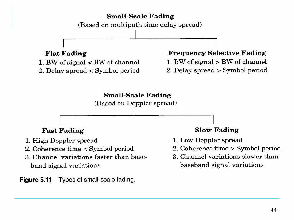
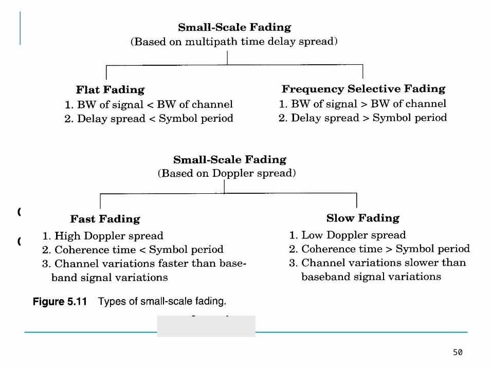
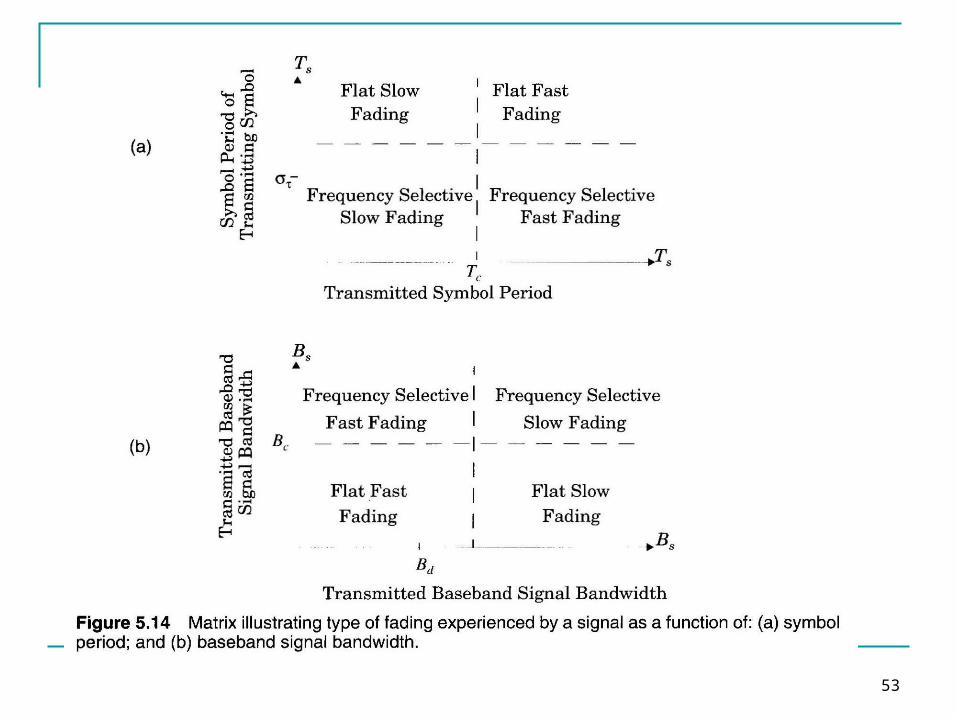
Classification of Multipath Channels Depending on the relation between signal
parameters (bandwidth and symbol period) and channel parameters (delay spread and Doppler spread) different signals undergo different types of fading
Based on delay spread the types of small scale fading are
Flat fading Frequency selective fading
Based on Doppler spread the types of small scale fading are
Fast fading Slow fading
46
Flat fading: Occurs when the amplitude of the received signal
changes with time Occurs when symbol period of the transmitted signal
is much larger than the Delay Spread of the channel Bandwidth of the applied signal is narrow.
The channel has a flat transfer function with almost linear phase, thus affecting all spectral components of the signal in the same way
May cause deep fades. Increase the transmit power to combat this situation.

47
Flat Fading
h(t, s(t) r(t)
0 TS 0 0 TS+
<< TS
Occurs when:BS << BC
andTS >>
BC: Coherence bandwidthBS: Signal bandwidthTS: Symbol period: Delay Spread

48
Frequency selective fading:A channel that is not a flat fading channel is called frequency selective fading because different frequencies within a signal are attenuated differently by the MRC.
Occurs when channel multipath delay spread is greater than the symbol period. Symbols face time dispersion Channel induces Intersymbol Interference (ISI)
Bandwidth of the signal s(t) is wider than the channel impulse response.

49
Frequency Selective Fading
h(t, s(t) r(t)
0 TS 0 0 TS+
>> TS
TS
Causes distortion of the received baseband signal
Causes Inter-Symbol Interference (ISI)Occurs when:
BS > BC
andTS <
As a rule of thumb: TS <
50
Frequency Selective Fading
h(t, s(t) r(t)
0 TS 0 0 TS+
>> TS
TS
Causes distortion of the received baseband signal
Causes Inter-Symbol Interference (ISI)Occurs when:
BS > BC
andTS <
As a rule of thumb: TS <

51
Fast Fading Rate of change of the channel characteristics
is larger than theRate of change of the transmitted signal
The channel changes during a symbol period. The channel changes because of receiver motion. Coherence time of the channel is smaller than the
symbol period of the transmitter signal
Occurs when:BS < BD
andTS > TC
BS: Bandwidth of the signalBD: Doppler SpreadTS: Symbol PeriodTC: Coherence Bandwidth
52
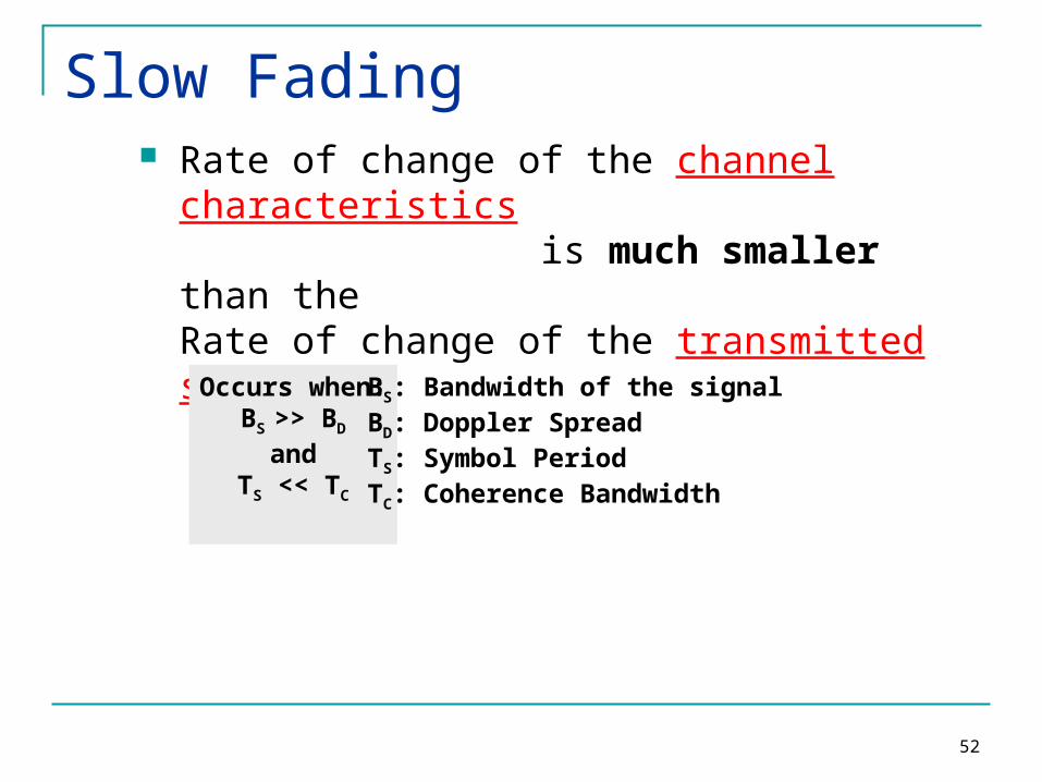
Slow Fading Rate of change of the channel characteristics
is much smaller than theRate of change of the transmitted signal
Occurs when:BS >> BD
andTS << TC
BS: Bandwidth of the signalBD: Doppler SpreadTS: Symbol PeriodTC: Coherence Bandwidth
53
54
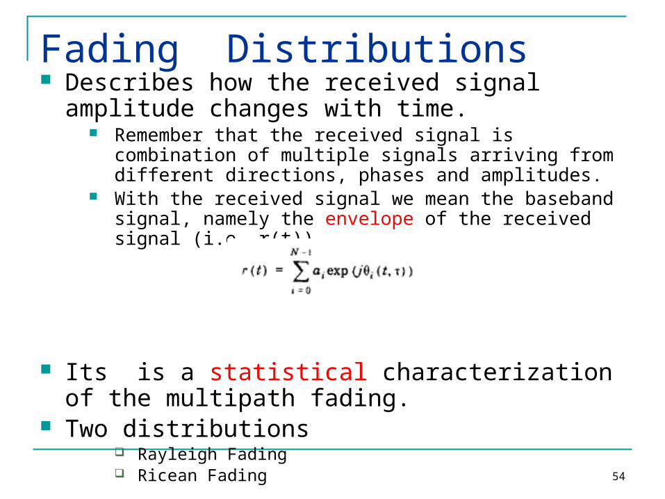
Fading Distributions Describes how the received signal amplitude
changes with time. Remember that the received signal is combination of multiple
signals arriving from different directions, phases and amplitudes.
With the received signal we mean the baseband signal, namely the envelope of the received signal (i.e. r(t)).
Its is a statistical characterization of the multipath fading.
Two distributions Rayleigh Fading Ricean Fading
55
Rayleigh and Ricean Distributions
Rayleigh: Describes the received signal envelope distribution for channels, where all the components are non-LOS:
i.e. there is no line-of–sight (LOS) component. Ricean: Describes the received signal
envelope distribution for channels where one of the multipath components is LOS component.
i.e. there is one LOS component.

56
Rayleigh Fading
57
Rayleigh
<
)(
)(
00
0)(2
2
22
r
rerrp
r
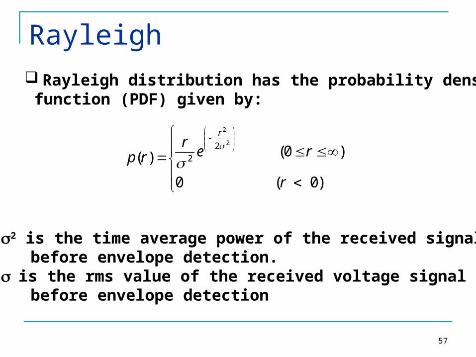
Rayleigh distribution has the probability density function (PDF) given by:
• 2 is the time average power of the received signal before envelope detection. • is the rms value of the received voltage signal before envelope detection
58
Rayleigh
R R
r edrrpRrPRP0
2 2
2
1)()()(
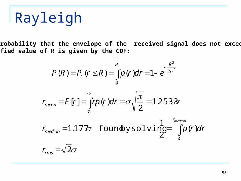
The probability that the envelope of the received signal does not exceed a specified value of R is given by the CDF:
2
)(21177.1
2533.12
)(][
0
0
rms
r
median
mean
r
drrpr
drrrprEr
median
solvingby found
59
0
0.1
0.2
0.3
0.4
0.5
0.6
0.7
0 1 2 3 4 5
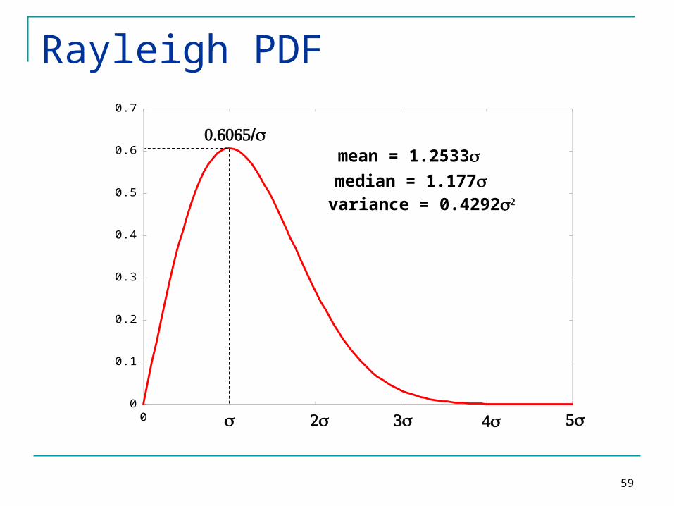
Rayleigh PDF
2 3 4 5
0.6065/mean = 1.2533median = 1.177variance = 0.42922

60
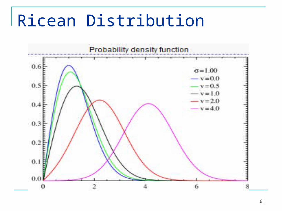
When there is a stationary (non-fading) LOS signal present, then the envelope distribution is Ricean.
The Ricean distribution degenerates to Rayleigh when the dominant component fades away.
The Pdf of Ricean function is given as
Ricean Distribution
61
Ricean Distribution


