
Chapter 3Describing Logic Circuits

Boolean Variables Boolean variables : ‘0’ or ‘1’
Logic 0 Logic 1False TrueOff OnLow HighNo YesOpen switch Closed switch
INC222 Logic Theory and Digital Circuit Design Chapter 3 Describing Logic Circuits

Boolean Algebra Boolean algebra : expressing the
relationship between a logic circuit’s inputs and outputs
Three basic operation : OR(+), AND(・), NOT(  ̄ )
INC222 Logic Theory and Digital Circuit Design Chapter 3 Describing Logic Circuits

Truth Tables Truth table : describing how a logic circuit’s
output depends on the logic levels present at the circuit’s inputs
Number of output combinations will equal 2N for an N-input truth table
INC222 Logic Theory and Digital Circuit Design Chapter 3 Describing Logic Circuits

OR Operation with OR Gates The Boolean expression for the OR
operations is
INC222 Logic Theory and Digital Circuit Design Chapter 3 Describing Logic Circuits

Example 3-1
INC222 Logic Theory and Digital Circuit Design Chapter 3 Describing Logic Circuits
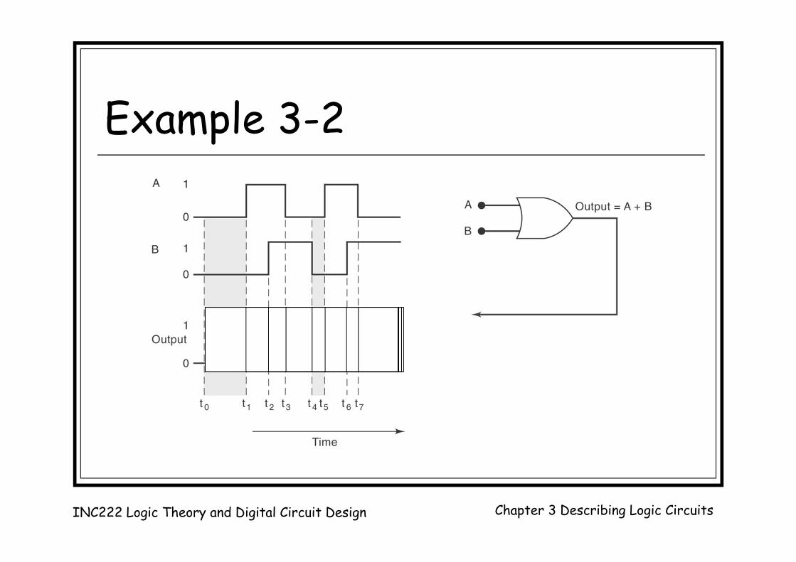
Example 3-2
INC222 Logic Theory and Digital Circuit Design Chapter 3 Describing Logic Circuits

AND Operation with AND Gates The Boolean expression for the AND
operations is
INC222 Logic Theory and Digital Circuit Design Chapter 3 Describing Logic Circuits

Example 3-9
INC222 Logic Theory and Digital Circuit Design Chapter 3 Describing Logic Circuits

NOT Operation The Boolean expression for NOT
Operation is
INC222 Logic Theory and Digital Circuit Design Chapter 3 Describing Logic Circuits

Summery of Boolean Operations
OR AND NOT0 + 0 = 0 0 ・ 0 = 0 0 = 10 + 1 = 1 0 ・ 1 = 0 1 = 01 + 0 = 1 1 ・ 0 = 01 + 1 = 1 1 ・ 1 = 1
INC222 Logic Theory and Digital Circuit Design Chapter 3 Describing Logic Circuits

Describing Logic Circuits Algebraically
INC222 Logic Theory and Digital Circuit Design Chapter 3 Describing Logic Circuits

Circuits Containing INVERTERs
INC222 Logic Theory and Digital Circuit Design Chapter 3 Describing Logic Circuits

Evaluating Logic-Circuit Outputs
INC222 Logic Theory and Digital Circuit Design Chapter 3 Describing Logic Circuits

Evaluating Logic-Circuit Outputs A=0, B=1, C=1, D=1 A=0, B=0, C=1, D=1, E=1
INC222 Logic Theory and Digital Circuit Design Chapter 3 Describing Logic Circuits

Evaluating a Boolean expression Perform all inversions of single terms Perform all operations within parentheses Perform an AND operation before an OR
operation If an expression has a bar over it, perform the
operations inside the expression first and then invert the result
INC222 Logic Theory and Digital Circuit Design Chapter 3 Describing Logic Circuits

Determining Output Level from a Diagram
INC222 Logic Theory and Digital Circuit Design Chapter 3 Describing Logic Circuits

Implementing Circuits from Boolean Expressions
INC222 Logic Theory and Digital Circuit Design Chapter 3 Describing Logic Circuits

NOR Gate The output
expression for NOR gate is
INC222 Logic Theory and Digital Circuit Design Chapter 3 Describing Logic Circuits

Example 3-8
INC222 Logic Theory and Digital Circuit Design Chapter 3 Describing Logic Circuits

NAND Gate The output expression for NAND gate is
INC222 Logic Theory and Digital Circuit Design Chapter 3 Describing Logic Circuits

Example 3-10
INC222 Logic Theory and Digital Circuit Design Chapter 3 Describing Logic Circuits

Boolean Theorems
INC222 Logic Theory and Digital Circuit Design Chapter 3 Describing Logic Circuits

AND
OR
INC222 Logic Theory and Digital Circuit Design Chapter 3 Describing Logic Circuits

Multivariable TheoremsCommutative laws
Associative laws
Distributive laws
INC222 Logic Theory and Digital Circuit Design Chapter 3 Describing Logic Circuits

DeMorgan’s Theorems
INC222 Logic Theory and Digital Circuit Design Chapter 3 Describing Logic Circuits

Implications of DeMorgan’s Theorems
INC222 Logic Theory and Digital Circuit Design Chapter 3 Describing Logic Circuits

Implications of DeMorgan’s Theorems (cont.)
INC222 Logic Theory and Digital Circuit Design Chapter 3 Describing Logic Circuits

Universality of NAND Gates
INC222 Logic Theory and Digital Circuit Design Chapter 3 Describing Logic Circuits

Universality of NOR Gates
INC222 Logic Theory and Digital Circuit Design Chapter 3 Describing Logic Circuits

Example 3-18
INC222 Logic Theory and Digital Circuit Design Chapter 3 Describing Logic Circuits

Alternate Logic-Gate Representations
INC222 Logic Theory and Digital Circuit Design Chapter 3 Describing Logic Circuits
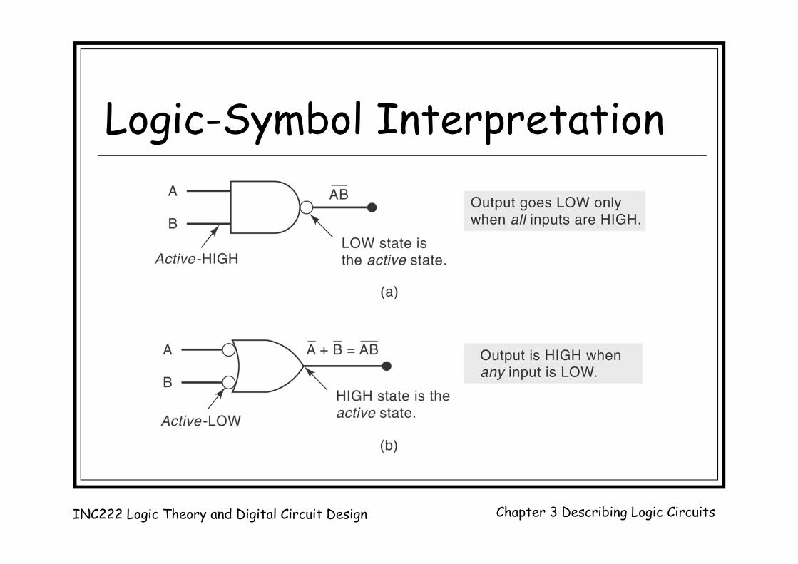
Logic-Symbol Interpretation
INC222 Logic Theory and Digital Circuit Design Chapter 3 Describing Logic Circuits


