23
Chatter - Causes and Solutions Prof. Dr.-Ing. Albert Albers
Dipl.-Ing. Daniel Herbst
Definition of Chatter Vibrations that arise during the slip phase of the clutch in the drive train of a motor vehicle and are generated in the clutch area should by definition be included under chatter. This definition is consciously kept general; it makes no statement on the causes of the vibrations. It is also used by other authors [1].
With an engaged clutch, the drive train can also vibrate in a frequency range similar to a true chatter. This “pseudo-chatter” can be caused by extreme lagging, defective engine mounts or a clunk in engagement and is often mistaken for true chatter.
Causes and Manifestations of Chatter Chatter is caused when a periodic torque change is generated in a slipping clutch, whose natural frequency range is similar to that of the drive train dynamically separated from the clutch. The first natural frequency of passenger car drive trains is between 8 and 12 Hz under these conditions and thus with an engine speed of approximately 480 to 720 rpm (with a 1st order of excitation).
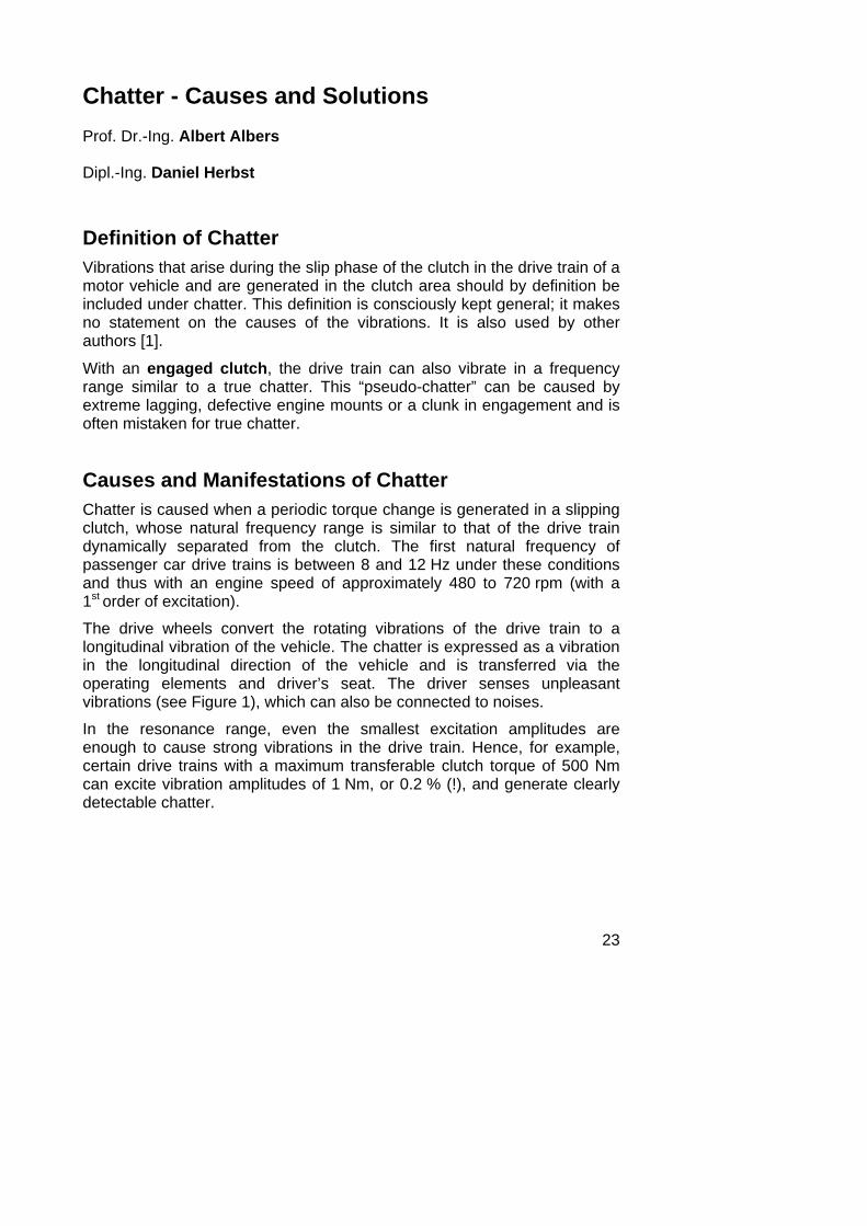
The drive wheels convert the rotating vibrations of the drive train to a longitudinal vibration of the vehicle. The chatter is expressed as a vibration in the longitudinal direction of the vehicle and is transferred via the operating elements and driver’s seat. The driver senses unpleasant vibrations (see Figure 1), which can also be connected to noises.
In the resonance range, even the smallest excitation amplitudes are enough to cause strong vibrations in the drive train. Hence, for example, certain drive trains with a maximum transferable clutch torque of 500 Nm can excite vibration amplitudes of 1 Nm, or 0.2 % (!), and generate clearly detectable chatter.
24
� � � � � � � � � � � � � � � � � � � � �
� � � � � � � � � � � � � � � � � � � � � � � � � � � � � � � � � � �
� � � � � � � � � � � � � � � � � � � � � � � � � � � � � � � � �
� � � � � � � � � � � � � � � � � � � � � � � � � � � � � �
Figure 1: Causes and manifestations of chatter
Physical Causes of the Types of Chatter Vibrations There are two different types of chatter vibrations that can occur:
• self-induced chatters (friction vibrations)
• pressure-induced chatters
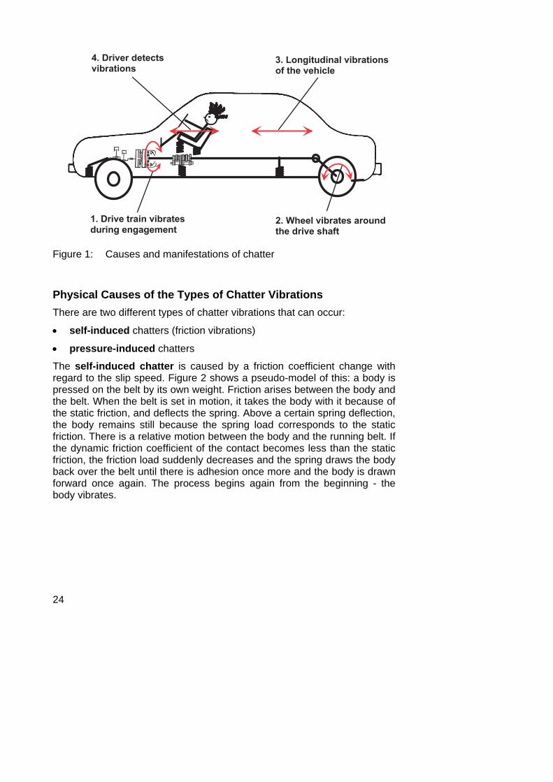
The self-induced chatter is caused by a friction coefficient change with regard to the slip speed. Figure 2 shows a pseudo-model of this: a body is pressed on the belt by its own weight. Friction arises between the body and the belt. When the belt is set in motion, it takes the body with it because of the static friction, and deflects the spring. Above a certain spring deflection, the body remains still because the spring load corresponds to the static friction. There is a relative motion between the body and the running belt. If the dynamic friction coefficient of the contact becomes less than the static friction, the friction load suddenly decreases and the spring draws the body back over the belt until there is adhesion once more and the body is drawn forward once again. The process begins again from the beginning - the body vibrates.
25
μ (v)
Figure 2: Pseudo-model for self-induced vibration
A vibration can thus only occur when the dynamic friction coefficient is lower than the static friction coefficient or the dynamic friction coefficient drops with increasing slip speed, because otherwise a stationary balance develops. If the dynamic friction coefficient decreases with increasing slip speed, the friction contact also acts as a stimulant, since the friction load - which counteracts the spring load - decreases when the slip begins and the body is accelerated more strongly via the spring load.
The characteristic size in this case represents the friction coefficient gradient. It is defined as the increase of the friction coefficient over the slip speed:
μ' = vd
dΔμ
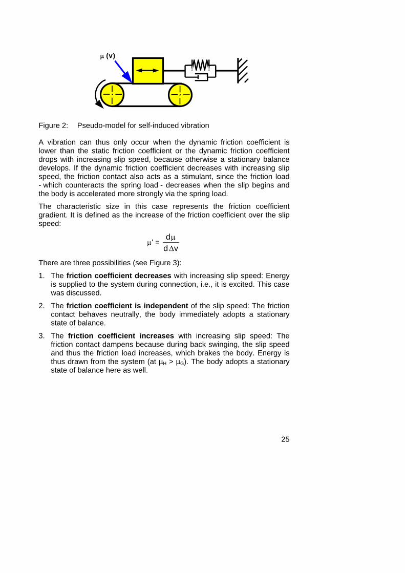
There are three possibilities (see Figure 3):
1. The friction coefficient decreases with increasing slip speed: Energy is supplied to the system during connection, i.e., it is excited. This case was discussed.
2. The friction coefficient is independent of the slip speed: The friction contact behaves neutrally, the body immediately adopts a stationary state of balance.
3. The friction coefficient increases with increasing slip speed: The friction contact dampens because during back swinging, the slip speed and thus the friction load increases, which brakes the body. Energy is thus drawn from the system (at µH > µG). The body adopts a stationary state of balance here as well.
26
μ' > 0
μ' = 0
μ' < 0
damping
neutral
exciting !
slip speed Δv
fric
tion
coe
ffic
ient
μ
Figure 3: Principle friction coefficient curves
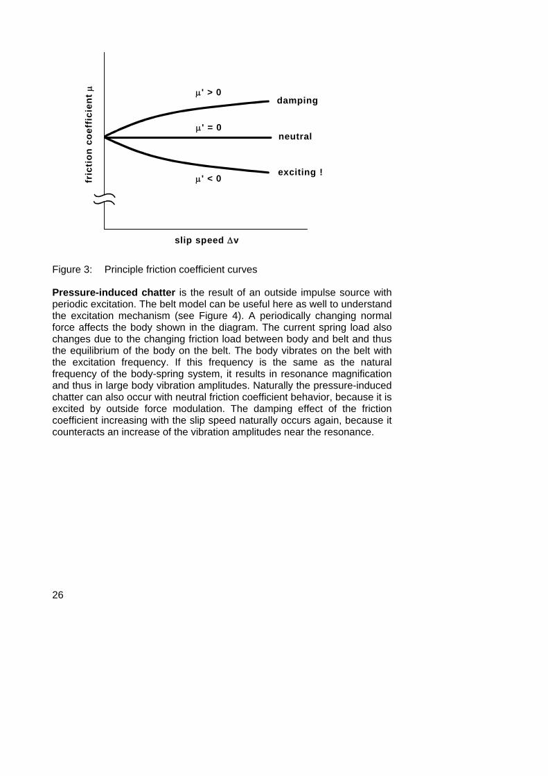
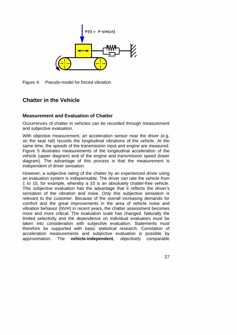
Pressure-induced chatter is the result of an outside impulse source with periodic excitation. The belt model can be useful here as well to understand the excitation mechanism (see Figure 4). A periodically changing normal force affects the body shown in the diagram. The current spring load also changes due to the changing friction load between body and belt and thus the equilibrium of the body on the belt. The body vibrates on the belt with the excitation frequency. If this frequency is the same as the natural frequency of the body-spring system, it results in resonance magnification and thus in large body vibration amplitudes. Naturally the pressure-induced chatter can also occur with neutral friction coefficient behavior, because it is excited by outside force modulation. The damping effect of the friction coefficient increasing with the slip speed naturally occurs again, because it counteracts an increase of the vibration amplitudes near the resonance.
27
F(t) ≈ F·sin(ωt)
Figure 4: Pseudo-model for forced vibration
Chatter in the Vehicle
Measurement and Evaluation of Chatter Occurrences of chatter in vehicles can be recorded through measurement and subjective evaluation.
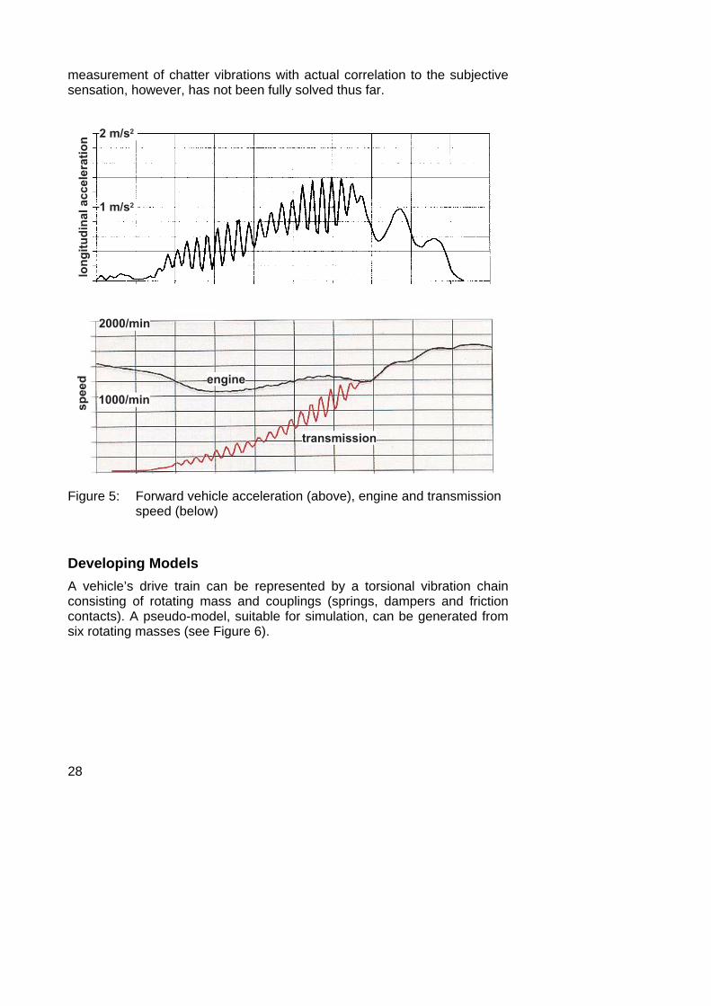
With objective measurement, an acceleration sensor near the driver (e.g. on the seat rail) records the longitudinal vibrations of the vehicle. At the same time, the speeds of the transmission input and engine are measured. Figure 5 illustrates measurements of the longitudinal acceleration of the vehicle (upper diagram) and of the engine and transmission speed (lower diagram). The advantage of this process is that the measurement is independent of driver sensation.
However, a subjective rating of the chatter by an experienced driver using an evaluation system is indispensable. The driver can rate the vehicle from 1 to 10, for example, whereby a 10 is an absolutely chatter-free vehicle. This subjective evaluation has the advantage that it reflects the driver’s sensation of the vibration and noise. Only this subjective sensation is relevant to the customer. Because of the overall increasing demands for comfort and the great improvements in the area of vehicle noise and vibration behavior (NVH) in recent years, the chatter assessment becomes more and more critical. The evaluation scale has changed. Naturally the limited selectivity and the dependence on individual evaluators must be taken into consideration with subjective evaluation. Statements must therefore be supported with basic statistical research. Correlation of acceleration measurements and subjective evaluation is possible by approximation. The vehicle-independent, objectively comparable
28
measurement of chatter vibrations with actual correlation to the subjective sensation, however, has not been fully solved thus far.
����������������������
� � � � � �
� � � � � �
�
� � � � � � � �
� � � � � � � �
� � � �
� � � � � � � � �
Figure 5: Forward vehicle acceleration (above), engine and transmission speed (below)
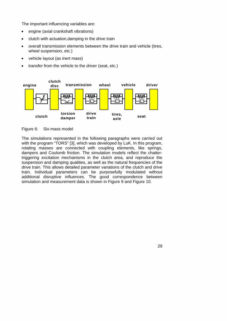
Developing Models A vehicle’s drive train can be represented by a torsional vibration chain consisting of rotating mass and couplings (springs, dampers and friction contacts). A pseudo-model, suitable for simulation, can be generated from six rotating masses (see Figure 6).
29
The important influencing variables are:
• engine (axial crankshaft vibrations)
• clutch with actuation,damping in the drive train
• overall transmission elements between the drive train and vehicle (tires, wheel suspension, etc.)
• vehicle layout (as inert mass)
• transfer from the vehicle to the driver (seat, etc.)
engineclutchdisc transmission wheel vehicle
clutchtorsiondamper
drivetrain
tires,axle seat
driver
Figure 6: Six-mass model
The simulations represented in the following paragraphs were carried out with the program “TORS” [3], which was developed by LuK. In this program, rotating masses are connected with coupling elements, like springs, dampers and Coulomb friction. The simulation models reflect the chatter-triggering excitation mechanisms in the clutch area, and reproduce the suspension and damping qualities, as well as the natural frequencies of the drive train. This allows detailed parameter variations of the clutch and drive train. Individual parameters can be purposefully modulated without additional disruptive influences. The good correspondence between simulation and measurement data is shown in Figure 9 and Figure 10.
30
Self-Induced Chatter (Facing Coefficient Gradient Chatter) As explained above, self-induced vibrations occur when the friction coefficient decreases while engaging during the slip phase with increasing slip speed in the friction contact. The friction coefficient is thus negative.
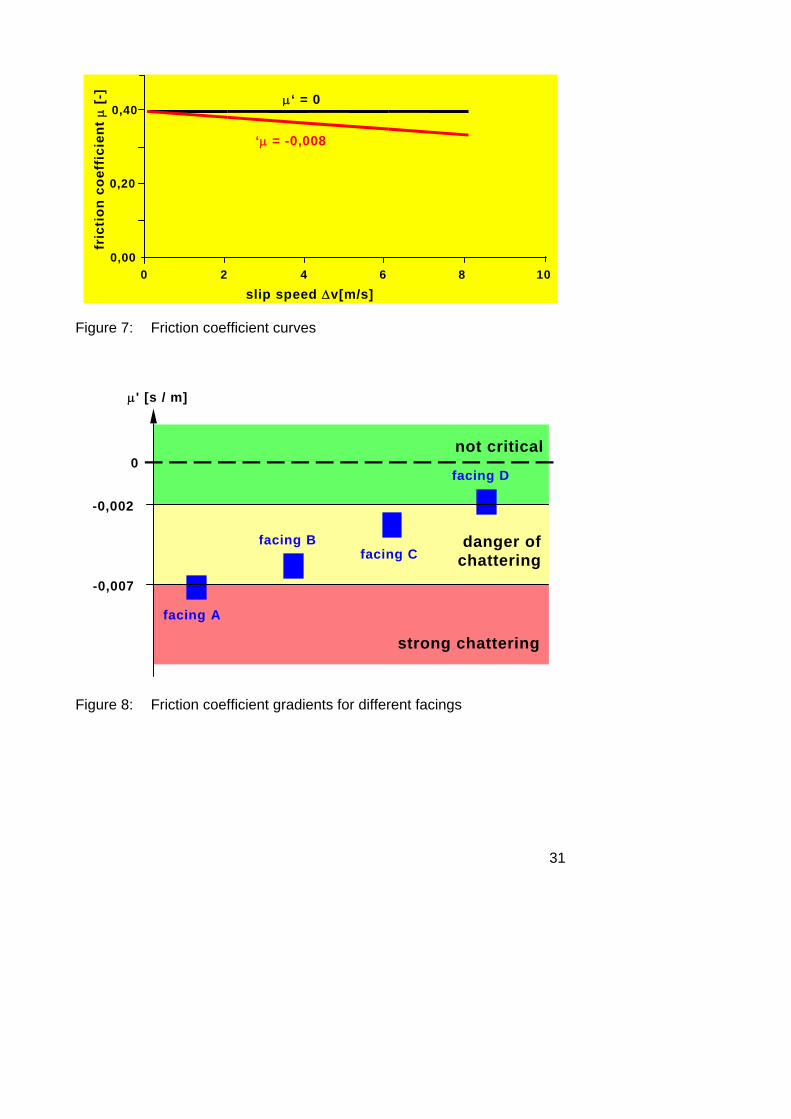
The friction coefficient gradients of today’s facings lie between μ' = 0 s/m and μ' = -0.015 s/m. Figure 7 illustrates real friction coefficient curves of clutch facings. It becomes clear that the friction coefficient gradients that are discussed and relevant here are very low and may in no way be evaluated with the excessive increases often used in principle representations (see Figure 3).
With some newly developed facings, positive gradients have already been achieved. In practice, however, the “chatter-sensitive” facings with certain operating conditions also have a decreasing friction coefficient and thus have the potential for excitation. On the other hand, there is no damping-free drive train. For this reason, there is always a certain remaining damping, so that a facing with only a slightly decreasing friction coefficient can lead to an overall chatter-free vehicle. For vehicles built at this time with drive train damping, a slightly negative friction coefficient gradient of μ' = -0.002 s/m is not critical (see Figure 7). If the friction coefficient increases strongly in the relevant slip speed range, damping occurs that can even eradicate the pressure-induced chatter. For this reason, a strongly positive friction coefficient gradient is the goal.
But even in such cases, the relationship can suddenly reverse itself when oil, grease or water enter the friction contact. The effect of moisture can be explained as follows: at high slip speeds, more heat is generated in the friction contact. Steam bubbles form, which allow the friction surfaces to float. Thus the friction coefficient is reduced. Rust-protection coating with sodium nitrite that was used formerly, prevents sticking, but is hygroscopic. Particularly after long periods of inoperation in humid weather, strong chatter can sometimes occur, because the water of crystalization is suddenly freed. After a few drives, the water evaporates and the chatter disappears again. Because the sodium nitrite is only used on the surfaces, this effect no longer occurs on facings that have been used longer. It may be surmised that a similar effect could occur with oil or grease contamination as with water.
31
fric
tion
coe
ffic
ient
μ [
-]
0,00
0,20
0,40
slip speed Δv[m/s]
‘μ = -0,008
μ‘ = 0
0 2 4 6 8 10
Figure 7: Friction coefficient curves
-0,002
μ' [s / m]
facing A
facing Bfacing C
-0,007
not critical
danger ofchattering
strong chattering
0facing D
Figure 8: Friction coefficient gradients for different facings
32
µ´ = - 0,010 s/m
µ´ = - 0,005 s/m
transmission
engine
time
spee
d
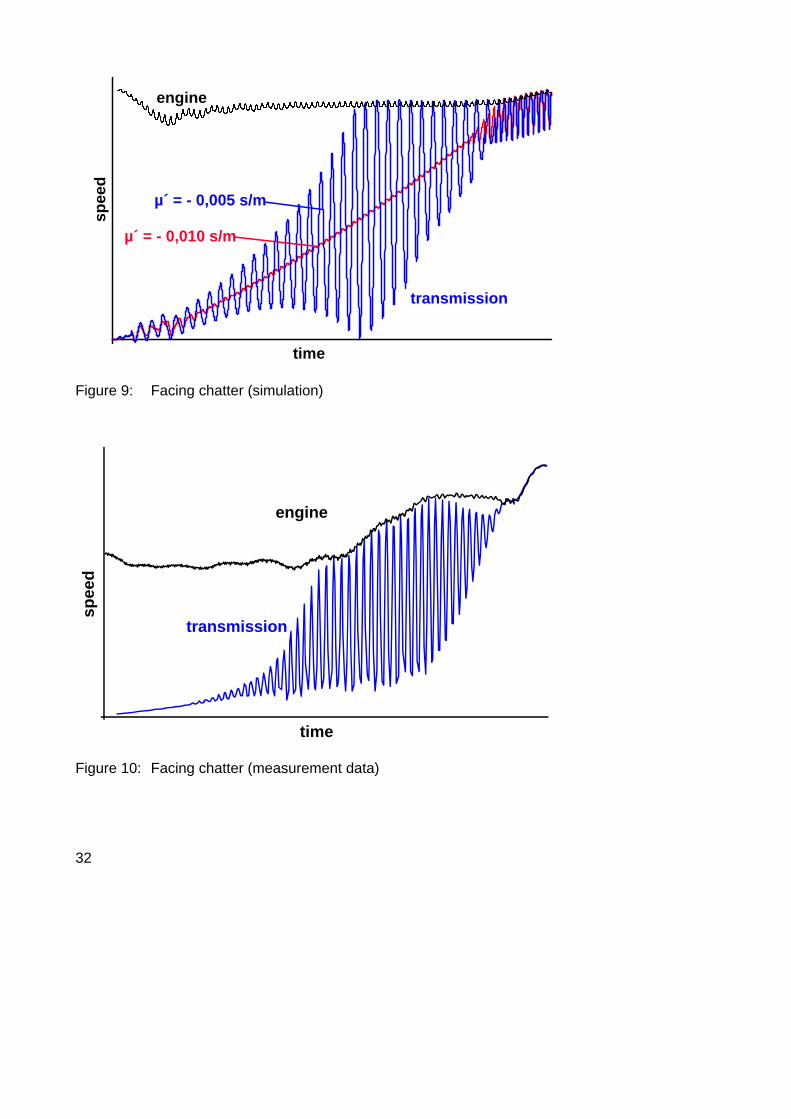
Figure 9: Facing chatter (simulation)
time
transmission
engine
spee
d
Figure 10: Facing chatter (measurement data)
33
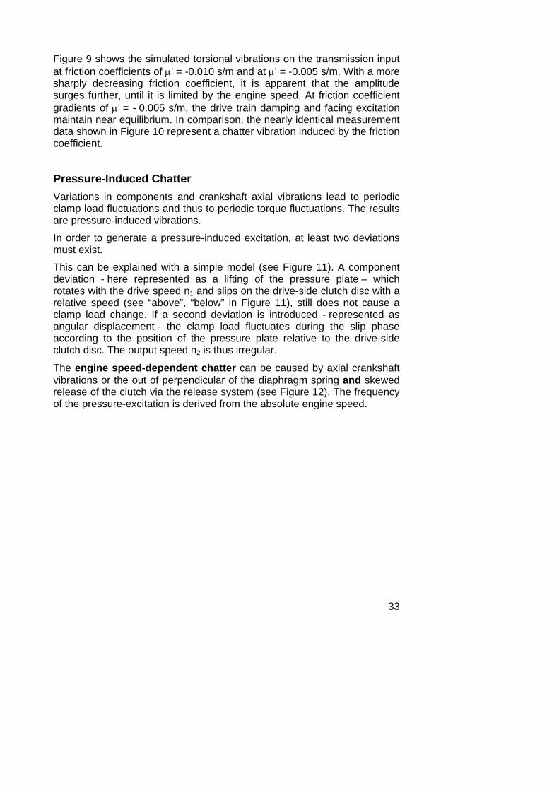
Figure 9 shows the simulated torsional vibrations on the transmission input at friction coefficients of μ' = -0.010 s/m and at μ' = -0.005 s/m. With a more sharply decreasing friction coefficient, it is apparent that the amplitude surges further, until it is limited by the engine speed. At friction coefficient gradients of μ' = - 0.005 s/m, the drive train damping and facing excitation maintain near equilibrium. In comparison, the nearly identical measurement data shown in Figure 10 represent a chatter vibration induced by the friction coefficient.
Pressure-Induced Chatter Variations in components and crankshaft axial vibrations lead to periodic clamp load fluctuations and thus to periodic torque fluctuations. The results are pressure-induced vibrations.
In order to generate a pressure-induced excitation, at least two deviations must exist.
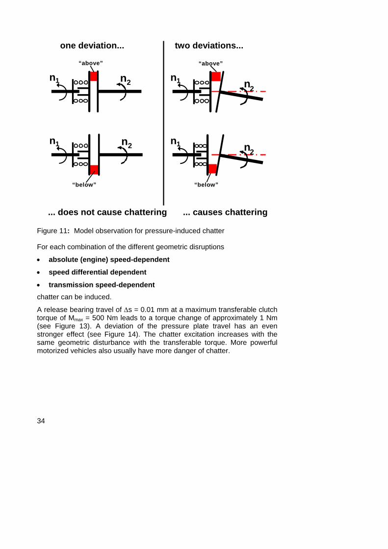
This can be explained with a simple model (see Figure 11). A component deviation - here represented as a lifting of the pressure plate – which rotates with the drive speed n1 and slips on the drive-side clutch disc with a relative speed (see “above”, “below” in Figure 11), still does not cause a clamp load change. If a second deviation is introduced - represented as angular displacement - the clamp load fluctuates during the slip phase according to the position of the pressure plate relative to the drive-side clutch disc. The output speed n2 is thus irregular.
The engine speed-dependent chatter can be caused by axial crankshaft vibrations or the out of perpendicular of the diaphragm spring and skewed release of the clutch via the release system (see Figure 12). The frequency of the pressure-excitation is derived from the absolute engine speed.
34
one deviation...
... does not cause chattering
two deviations...
... causes chattering
n2 n2n1 n1
“above” “above”
n1
“below” “below”
n2n1 n2
Figure 11: Model observation for pressure-induced chatter
For each combination of the different geometric disruptions
• absolute (engine) speed-dependent
• speed differential dependent
• transmission speed-dependent chatter can be induced.
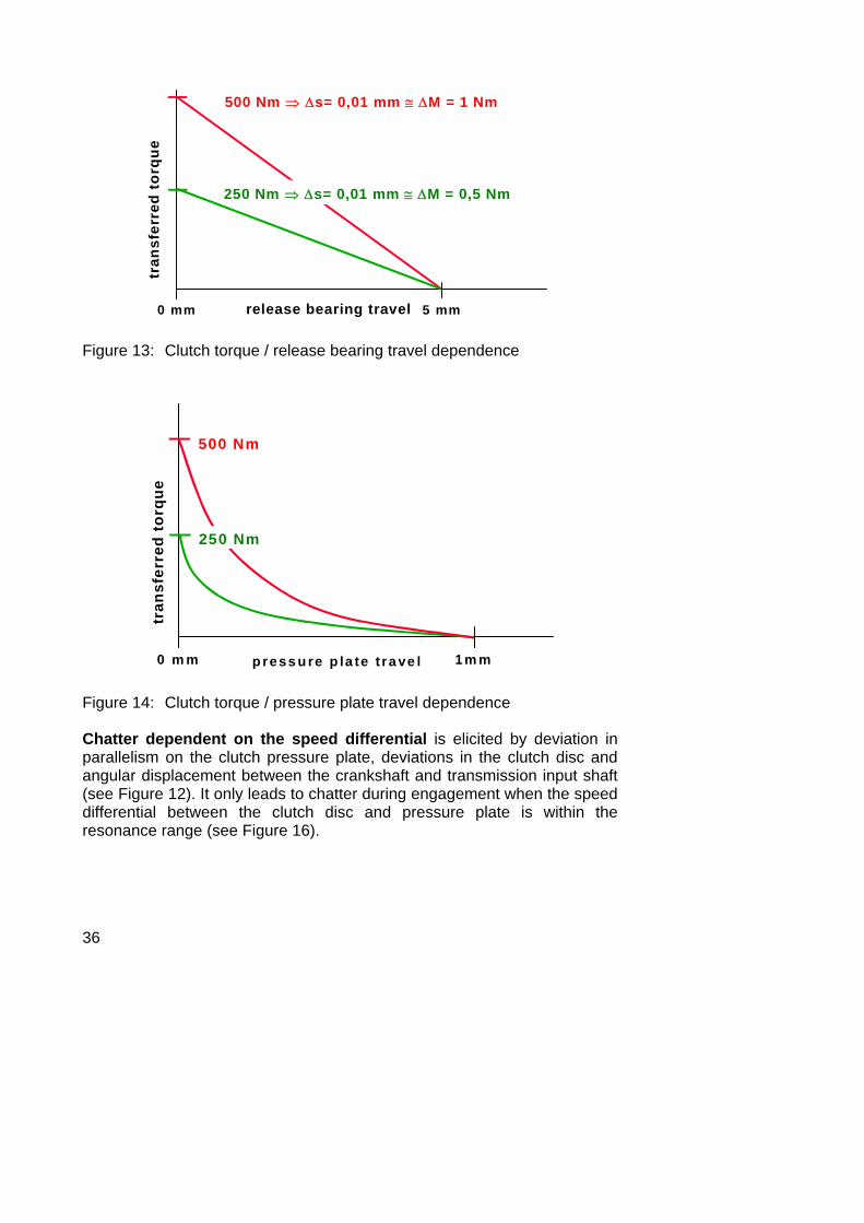
A release bearing travel of Δs = 0.01 mm at a maximum transferable clutch torque of Mmax = 500 Nm leads to a torque change of approximately 1 Nm (see Figure 13). A deviation of the pressure plate travel has an even stronger effect (see Figure 14). The chatter excitation increases with the same geometric disturbance with the transferable torque. More powerful motorized vehicles also usually have more danger of chatter.
35
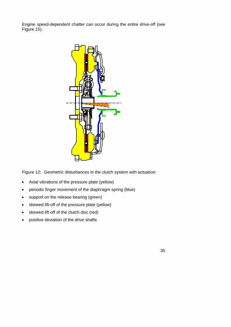
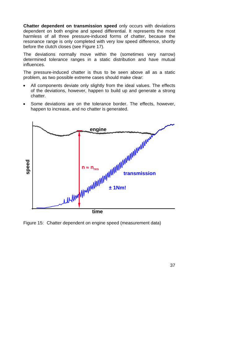
Engine speed-dependent chatter can occur during the entire drive-off (see Figure 15).
Figure 12: Geometric disturbances in the clutch system with actuation:
• Axial vibrations of the pressure plate (yellow)
• periodic finger movement of the diaphragm spring (blue)
• support on the release bearing (green)
• skewed lift-off of the pressure plate (yellow)
• skewed lift-off of the clutch disc (red)
• positive deviation of the drive shafts
36
release bearing travel
tran
sfer
red
torq
ue
500 Nm ⇒ Δs= 0,01 mm ≅ ΔM = 1 Nm
5 mm0 mm
250 Nm ⇒ Δs= 0,01 mm ≅ ΔM = 0,5 Nm
Figure 13: Clutch torque / release bearing travel dependence
p ress u re p la te t ra ve l
500 Nm
1 m m
250 Nm
tran
sfer
red
torq
ue
0 m m
Figure 14: Clutch torque / pressure plate travel dependence
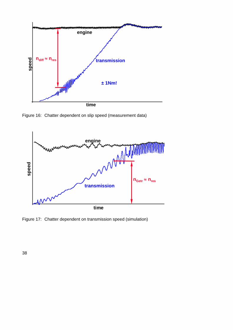
Chatter dependent on the speed differential is elicited by deviation in parallelism on the clutch pressure plate, deviations in the clutch disc and angular displacement between the crankshaft and transmission input shaft (see Figure 12). It only leads to chatter during engagement when the speed differential between the clutch disc and pressure plate is within the resonance range (see Figure 16).
37
Chatter dependent on transmission speed only occurs with deviations dependent on both engine and speed differential. It represents the most harmless of all three pressure-induced forms of chatter, because the resonance range is only completed with very low speed difference, shortly before the clutch closes (see Figure 17).
The deviations normally move within the (sometimes very narrow) determined tolerance ranges in a static distribution and have mutual influences.
The pressure-induced chatter is thus to be seen above all as a static problem, as two possible extreme cases should make clear:
• All components deviate only slightly from the ideal values. The effects of the deviations, however, happen to build up and generate a strong chatter.
• Some deviations are on the tolerance border. The effects, however, happen to increase, and no chatter is generated.
n ≈ nres
time
transmission
engine
spee
d
± 1Nm!
Figure 15: Chatter dependent on engine speed (measurement data)
38
ndiff ≈ nres
time
transmission
enginesp
eed
± 1Nm!
Figure 16: Chatter dependent on slip speed (measurement data)
time
spee
d
transmission
engine
nGetr ≈ nres
Figure 17: Chatter dependent on transmission speed (simulation)
39
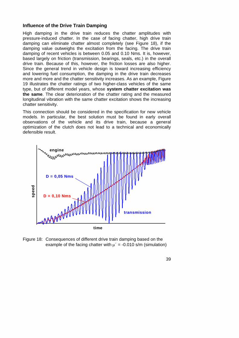
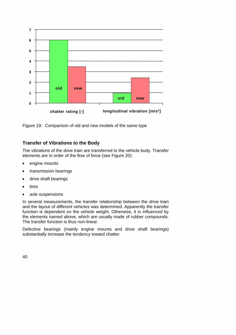
Influence of the Drive Train Damping High damping in the drive train reduces the chatter amplitudes with pressure-induced chatter. In the case of facing chatter, high drive train damping can eliminate chatter almost completely (see Figure 18), if the damping value outweighs the excitation from the facing. The drive train damping of recent vehicles is between 0.05 and 0.10 Nms. It is, however, based largely on friction (transmission, bearings, seals, etc.) in the overall drive train. Because of this, however, the friction losses are also higher. Since the general trend in vehicle design is toward increasing efficiency and lowering fuel consumption, the damping in the drive train decreases more and more and the chatter sensitivity increases. As an example, Figure 19 illustrates the chatter ratings of two higher-class vehicles of the same type, but of different model years, whose system chatter excitation was the same. The clear deterioration of the chatter rating and the measured longitudinal vibration with the same chatter excitation shows the increasing chatter sensitivity.
This connection should be considered in the specification for new vehicle models. In particular, the best solution must be found in early overall observations of the vehicle and its drive train, because a general optimization of the clutch does not lead to a technical and economically defensible result.
D = 0,10 Nms
D = 0,05 Nms
transmission
engine
time
spee
d
Figure 18: Consequences of different drive train damping based on the example of the facing chatter with μ´ = -0.010 s/m (simulation)
40
0
1
2
3
4
5
6
7
chatter rating [-] longitudinal vibration [m/s²]
old new
old new
Figure 19: Comparison of old and new models of the same type
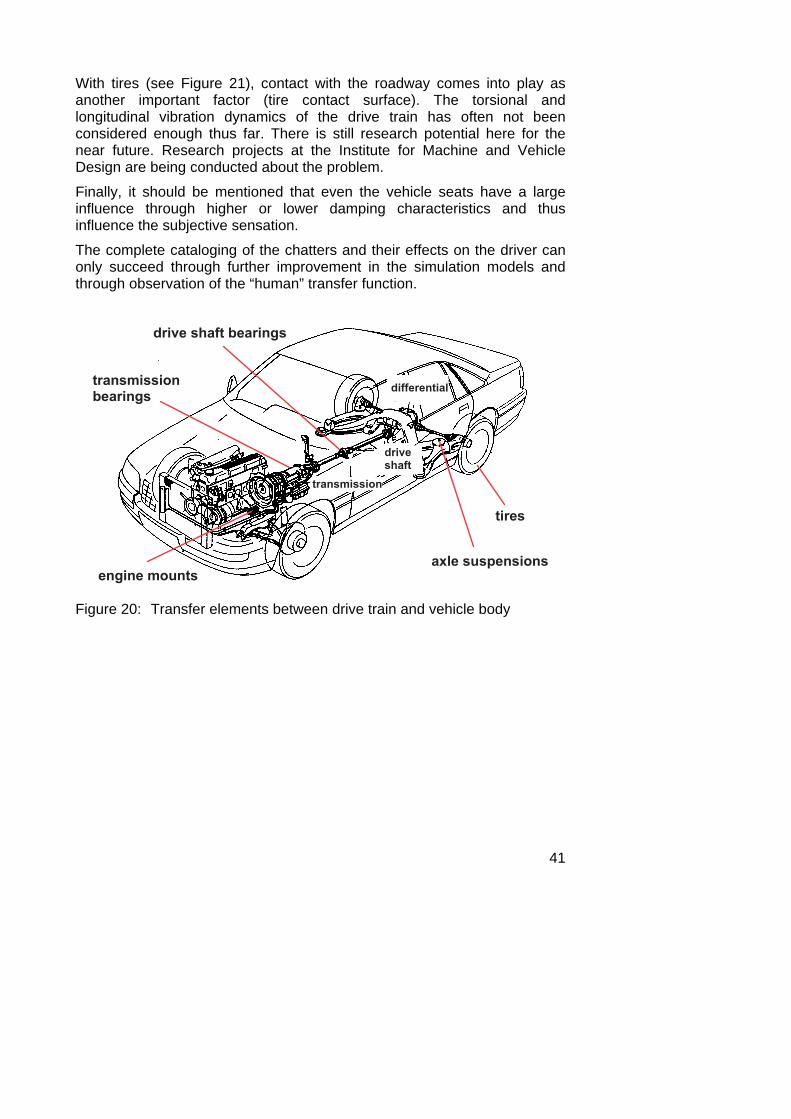
Transfer of Vibrations to the Body The vibrations of the drive train are transferred to the vehicle body. Transfer elements are in order of the flow of force (see Figure 20):
• engine mounts
• transmission bearings
• drive shaft bearings
• tires
• axle suspensions
In several measurements, the transfer relationship between the drive train and the layout of different vehicles was determined. Apparently the transfer function is dependent on the vehicle weight. Otherwise, it is influenced by the elements named above, which are usually made of rubber compounds. The transfer function is thus non-linear.
Defective bearings (mainly engine mounts and drive shaft bearings) substantially increase the tendency toward chatter.
41
With tires (see Figure 21), contact with the roadway comes into play as another important factor (tire contact surface). The torsional and longitudinal vibration dynamics of the drive train has often not been considered enough thus far. There is still research potential here for the near future. Research projects at the Institute for Machine and Vehicle Design are being conducted about the problem.
Finally, it should be mentioned that even the vehicle seats have a large influence through higher or lower damping characteristics and thus influence the subjective sensation.
The complete cataloging of the chatters and their effects on the driver can only succeed through further improvement in the simulation models and through observation of the “human” transfer function.
� � � � � � � � � � � � � � �
� � � � � � � � �� � � � � �
� � �
� � � � � � � � � � � � � � � � � � �
� � � � � � � � �
� � � � � � � � � � � � �
� � � � � � � � �
Figure 20: Transfer elements between drive train and vehicle body
42
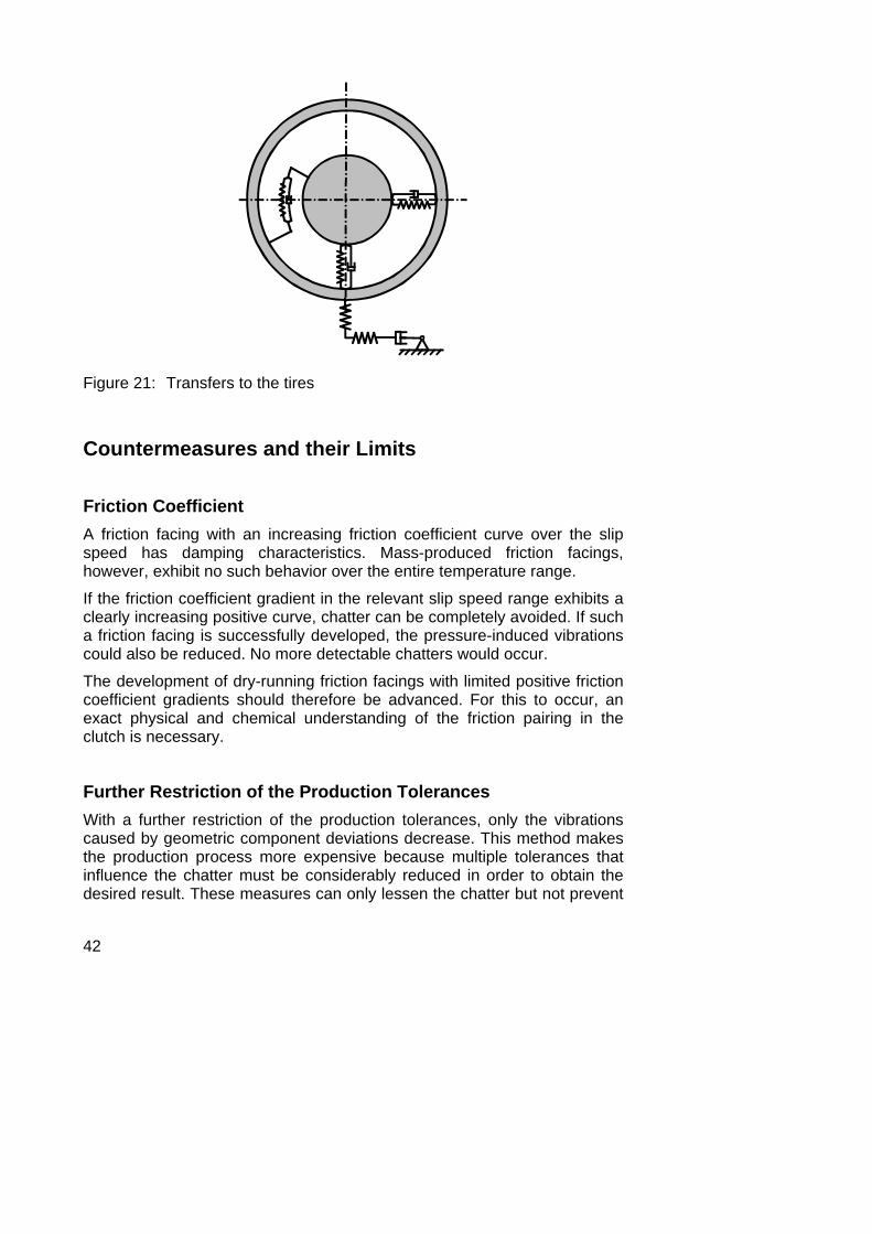
Figure 21: Transfers to the tires
Countermeasures and their Limits
Friction Coefficient A friction facing with an increasing friction coefficient curve over the slip speed has damping characteristics. Mass-produced friction facings, however, exhibit no such behavior over the entire temperature range.
If the friction coefficient gradient in the relevant slip speed range exhibits a clearly increasing positive curve, chatter can be completely avoided. If such a friction facing is successfully developed, the pressure-induced vibrations could also be reduced. No more detectable chatters would occur. The development of dry-running friction facings with limited positive friction coefficient gradients should therefore be advanced. For this to occur, an exact physical and chemical understanding of the friction pairing in the clutch is necessary.
Further Restriction of the Production Tolerances With a further restriction of the production tolerances, only the vibrations caused by geometric component deviations decrease. This method makes the production process more expensive because multiple tolerances that influence the chatter must be considerably reduced in order to obtain the desired result. These measures can only lessen the chatter but not prevent
43
it, as long as a facing with chatter-sensitive quality is used, because the pressure-induced chatter can only be reduced in this way.
With today’s clutches, a pressure plate typically has a straightness value, measured at a particular circumference, of 0.1 mm. A reduction in this value means a considerable additional production expense, due to surface grinding, for example.
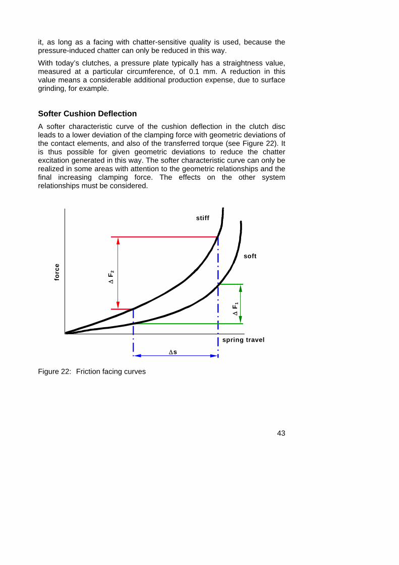
Softer Cushion Deflection A softer characteristic curve of the cushion deflection in the clutch disc leads to a lower deviation of the clamping force with geometric deviations of the contact elements, and also of the transferred torque (see Figure 22). It is thus possible for given geometric deviations to reduce the chatter excitation generated in this way. The softer characteristic curve can only be realized in some areas with attention to the geometric relationships and the final increasing clamping force. The effects on the other system relationships must be considered.
spring travel
forc
e
stiff
soft
Δs
Δ F
2
Δ F
1
Figure 22: Friction facing curves
44
Damping in the Drive Train High damping in the drive train can entirely eliminate the facing chatter and reduce the pressure-induced chatter. A damping increase, through higher viscosity transmission lubricants, for example, is not realized because it is not effective enough.
The chatter vibrations occur only during the slip phase of the clutch. Thus it is worth considering integrating a switchable vibration damper. An electronically controlled eddy current brake would be conceivable here. The development is nevertheless made difficult by the specification guidelines (installation, weight, cost).
Countermeasures on the Assembly Side The pressure-induced chatter can be effectively reduced on the assembly side. Here, all measures are significant that generate components with the natural tensions and deformities within tolerances. The force-free screwing down of the pressure plate can - as many concrete applications can prove - improve the geometric disturbances in assembled clutch systems.
Summary Chatter occurs only during the slip phase of the clutch and is divided into two different types:
• self-induced facing chatter induced by the friction coefficient
• pressure-induced chatter as a result of component deviations and axial vibrations
The significance of the facing chatter is decreasing because the facings are getting better. For this reason pressure-induced chatter occurs more often, because the drive train damping of modern vehicles is falling for efficiency reasons and thus ever-smaller deviations in the torque in the clutch area lead to chatter problems in the vehicle. In addition, engine performance is increasing on average, whereby the clutch must transfer more torque and thus the torque deviations increase. Finally, due to increasing comfort demands and the clear improvement in the vehicle’s general noise and vibration behavior achieved in recent years, sporadically occurring small chatter becomes more relevant to the customer.
The chatter vibrations are influenced not only by the clutch and the actuation system itself, but also by the engine, the drive train and the drive shaft, the axle suspension and the vehicle layout. All transfer elements influence the chatter sensitivity and must be considered.
45
A chatter-insensitive clutch without additional new components or assemblies is possible with today’s technology if:
• the facing has an increasing friction coefficient gradient
• a soft cushion deflection is built in
• the production tolerances are logically restricted
• natural tensions are avoided in assembly
Understanding the causes, transfers and effects of chatter vibrations in relation to the entire vehicle system must still be further improved through research in order to avoid or protect against chatter in the development of new vehicles now. Finally it must be determined that chatter cannot be prevented long-term through isolated measures on one part of the vehicle - such as for example the clutch - but only through observation and tuning of the entire vehicle system.
Literature [1] Winkelmann, S.; Harmuth, H.:
Schaltbare Reibkupplungen, Konstruktionsbücher Band 34; 1985
[2] Pfeiffer, F.: Das Phänomen der selbsterregten Schwingungen, VDI-Berichte Nr. 957 (1992), S. 1
[3] Seebacher, R.; Fischer, R.: Triebstrangabstimmung mit Simulationsunterstützung, VDI-Berichte Nr. 1285 (1996), S. 395
[4] Maucher, P.: Kupplungsrupfen, Möglichkeiten zur Vermeidung, 4. LuK-Kolloquium 1990
[5] Albers, A.: Elektronisches Kupplungsmanagement die mitdenkende Kupplung, 4. LuK-Kolloquium 1990


