
Chapter 5Circuit Theorems
Seoul National University
Department of Electrical and Computer Engineering
Prof. SungJune Kim

Department of Electrical and Computer Engineering, SNU
Prof. SungJune Kim
Non ideal sources
Ideal sources: voltage source and current source:
There is no source resistances and there is no loading effect.
Non ideal voltage source with loading effect:
v decreases with i.
(As RL decreases, i increases and v decreases linearly (to i)).
Intercepts are voc(t) and isc(t), Slope is RTh
v(t)
i(t)
voc(t)
isc(t)sc
ocTh
i
vR
iRvv thoc
RL
v+
-
i

Department of Electrical and Computer Engineering, SNU
Prof. SungJune Kim
Source Transformations
Source transformation
The conversion of a nonideal voltage source to a nonideal current source. Or
vice versa.
Replacing the nonideal voltage (or current) source by the the other nonideal
current (or voltage) source should not change the voltage or current of any
element in circuit B (Then the two sources are equivalent.)

Department of Electrical and Computer Engineering, SNU
Prof. SungJune Kim
Source Transformations (cont’d)
Source transformation
: For two extreme cases,
For short circuit condition (R=0)
For open circuit condition (R=∞)
For both circuits to be equivalent
s
sss
s
s
R
viiib
R
via )()(
psspss RivRivbvva )()(
spsss RRRiv ,
sp
p
s
spss
RR
RR
vRiv

Department of Electrical and Computer Engineering, SNU
Prof. SungJune Kim
Source Transformations (cont’d)
Source transformation
: In general,
For the circuit of figure 5.2-2a we use KVL to obtain
Dividing by Rs gives
If we use KCL for the circuit of figure 5.2-2b, we have
Thus, the two circuits are equivalent when is=vs/Rs and Rs=Rp
viRv ss
ss
s
R
vi
R
v
p
sR
vii

Department of Electrical and Computer Engineering, SNU
Prof. SungJune Kim
Source Transformations
Method for Source transformations
Department of Electrical and Computer Engineering, SNU
Prof. SungJune Kim
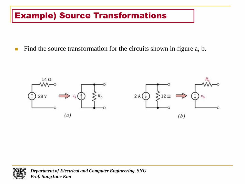
Example) Source Transformations
Find the source transformation for the circuits shown in figure a, b.

Department of Electrical and Computer Engineering, SNU
Prof. SungJune Kim
Solution
A214
28
s
ss
R
vi
V24)12(2 pss Riv
Current source
Voltage source

Department of Electrical and Computer Engineering, SNU
Prof. SungJune Kim
Example) Source Transformations
A circuit is shown in figure. Find the current i by reducing the circuit to the
right of terminals a-b to its simplest form using source transformations.

Department of Electrical and Computer Engineering, SNU
Prof. SungJune Kim
Solution
A1.030
3
p
ss
R
vi
V2.1)12(1.02 sss Riv
A224.0)125(
V)2.15(
i
1230//202pR
Current source
Combining two parallel resistances
Voltage source
Current i

Department of Electrical and Computer Engineering, SNU
Prof. SungJune Kim
Example 5.2-1 Source Transformations
First, determine the values of ip and Rp that cause the part of the circuit
connected to the 2 kohm resistor in Figure a. Next, determine the values of
va and vb.

Department of Electrical and Computer Engineering, SNU
Prof. SungJune Kim
Solution
mAAip 2002.06000
12 kRp 6
Source transformation
Voltage division
Voltage across the parallel resistors
As expected, the source transformation did not change the value of the voltage
across the 2kohm resistor
Vva 3)12(60002000
2000
ViR
Rv p
p
p
b 3)002.0(1500)002.0(60002000
)6000(2000
2000
2000

Department of Electrical and Computer Engineering, SNU
Prof. SungJune Kim
Superposition
A Linear element satisfies superposition when it satisfies fallowing
response and excitation relationship.
where, the arrows imply the excitation and the resulting response.
Department of Electrical and Computer Engineering, SNU
Prof. SungJune Kim
Superposition (cont’d)
Superposition principle: For a linear circuit consisting of linear elements
and independent sources, we can determine the total response by finding
the response to each independent source with all other independent
source set to zero and then summing these individual responses
Source deactivation
Independent voltage source: short circuit
Independent current source: open circuit
Dependent source must remain active during the superposition process
Power and Superposition
For dc circuit analysis, the principle of superposition does not apply to power
calculation.
Department of Electrical and Computer Engineering, SNU
Prof. SungJune Kim
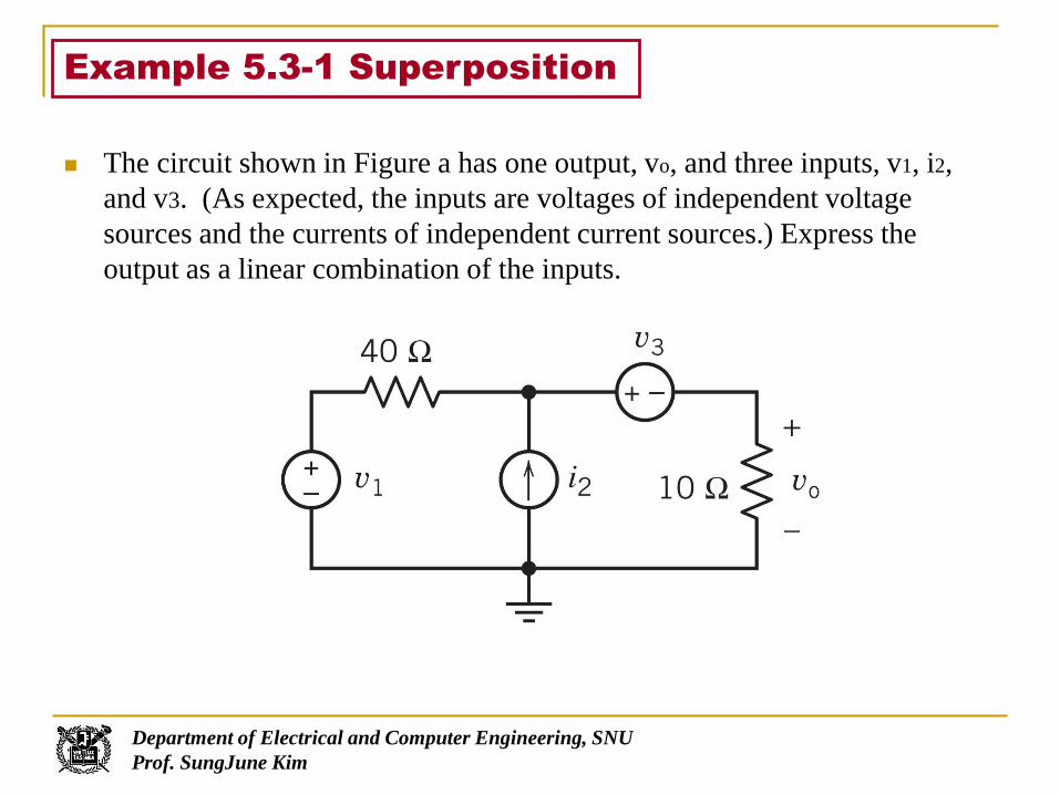
The circuit shown in Figure a has one output, vo, and three inputs, v1, i2,
and v3. (As expected, the inputs are voltages of independent voltage
sources and the currents of independent current sources.) Express the
output as a linear combination of the inputs.
Example 5.3-1 Superposition

Department of Electrical and Computer Engineering, SNU
Prof. SungJune Kim
Solution
1040
)(2
31 oo vi
vvv
Apply KCL to the supernode to get
ooo vvivvivvv 540440)( 321231
)40(5
1321 vivvo

Department of Electrical and Computer Engineering, SNU
Prof. SungJune Kim
Find the current i for the circuit of Figure 5.3-6a.
Example 5.3-2 Superposition

Department of Electrical and Computer Engineering, SNU
Prof. SungJune Kim
Independent voltage source acting alone (Fig. 5.3-2b)
Apply KVL to the loop
Independent current source acting alone (Fig. 5.3-2c)
(a) Controlling current of the dependent source
(b) Apply KCL at node a
The current, i, is equal to the sum of the currents, i1, i2
Solution
A303)23(24 111 iii
22 33
ivv
i aa
A4
5
4
7321 iii
A4
7
2
337
2
37 2
222
22
i
iii
ivi a

Department of Electrical and Computer Engineering, SNU
Prof. SungJune Kim
Thévenin’s theorem
Any circuit with sources (dependent and/or independent) and resistors
can be replaced by an equivalent circuit containing a single source and a
single resistor.
Thevenin’s theorem implies that we can replace arbitrarily complicated
networks with simple networks for purposes of analysis.
(a) A circuit partitioned with two parts: circuit A and circuit B
(b) Replacing circuit A by its Thevenin equivalent circuit

Department of Electrical and Computer Engineering, SNU
Prof. SungJune Kim
Thévenin’s theorem(1)
“Given any linear circuit, rearrange it in the form of two networks A and B connected
by two wires. Define a voltage voc as the open-circuit voltage which appears across
to the terminals of A when B is disconnected. Then all currents and voltages in B
will remain unchanged if all independent voltage and current sources in A are
“killed” or “zeroed out” and an independent voltage source voc is connected , with
proper polarity, in series with the dead (inactive) A network.”

Department of Electrical and Computer Engineering, SNU
Prof. SungJune Kim
Find the Thévenin’s Equivalent Circuit
: Independent Source
If the circuit contains resistors and independent sources,
Voc : Open circuit으로 구함
Rt : independent voltage source short
independent current source open으로 놓고 (즉, 전원을 deactivate 시키고, 두 단자 사이의 등가 저항을 구한다.

Department of Electrical and Computer Engineering, SNU
Prof. SungJune Kim
Example 5.4-1 Thévenin Equivalent Circuit
Using Thévenin’s theorem, find the current i through the resistor R in the
circuit of Figure 5.4-5.

Department of Electrical and Computer Engineering, SNU
Prof. SungJune Kim
Solution
2002
50
125 ococ vv
Vvoc 20
sci 0250
125
Aisc 5.0

Department of Electrical and Computer Engineering, SNU
Prof. SungJune Kim
Example) Thévenin Equivalent Circuit
Find the Thévenin equivalent circuit for the circuit shown in Figure 5.4-7

Department of Electrical and Computer Engineering, SNU
Prof. SungJune Kim
Solution
1. All the source deactivated (Fig. 5.4-8)
2. Open-circuit voltage at terminals a-b. (Fig 5.4-7)
3. Therefore, the Thevenin equivalent circuit is as
shown in Figure 5.4-9
12tR
V8
024010
10
c
cc
v
vv

Department of Electrical and Computer Engineering, SNU
Prof. SungJune Kim
Example 5.4-3 Thévenin Equivalent Circuit
Using Thévenin’s theorem shown in Figure 5.4-13. Determine the current i
as a function of R.

Department of Electrical and Computer Engineering, SNU
Prof. SungJune Kim
Solution
A8
40
Ri

Department of Electrical and Computer Engineering, SNU
Prof. SungJune Kim
Find the Thévenin’s Equivalent Circuit
: independent and dependent sources If the circuit contains resistors and two kinds of sources,
Find Voc and Isc, then Rt= Voc/Isc
Connect an open circuit between terminals a and b . Find Voc=Vab, the
voltage across the open circuit.
Connect a short circuit between terminals a and b Find Isc, the current
directed from a to b in the short circuit.

Department of Electrical and Computer Engineering, SNU
Prof. SungJune Kim
Example) Thévenin Equivalent Circuits and Dependent Source
Find the Thévenin equivalent circuit for the circuit shown in Figure 5.4-8.

Department of Electrical and Computer Engineering, SNU
Prof. SungJune Kim
Solution
1. Open circuit voltage voc=vab.
KVL around the mesh of Fig 5.4-11
2. Short circuit current
for the circuit of Fig 5.4-12
Using two mesh currents
Therefore
V126
A2
062620
iv
i
iii
oc
6.13136/120
12
A136/1202
sc
oct
sc
i
vR
ii
010)(6
0)6(2620
221
211
iii
iiii
Department of Electrical and Computer Engineering, SNU
Prof. SungJune Kim
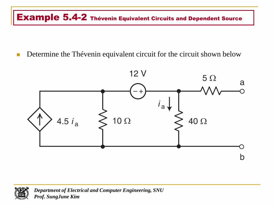
Example 5.4-2 Thévenin Equivalent Circuits and Dependent Source
Determine the Thévenin equivalent circuit for the circuit shown below

Department of Electrical and Computer Engineering, SNU
Prof. SungJune Kim
Solution
1. Open circuit voltage
2. Short circuit current
3. Thévenin resistance
40
oca
vi
Vv
iv
oc
aoc
96
)5.3(10120
scscscbscaba iiiiiiii16
95.3)(5.4
80405 sc
aasc
iiii
Aisc 1294.1
tabbata iiiiiii 5.3)(5.4
tataba iiiiii 2)5.3(101040
btt iiv 105 85t
tt
i
vR

Department of Electrical and Computer Engineering, SNU
Prof. SungJune Kim
Find the Thévenin’s Equivalent Circuit
: Dependent Source (As in the transistor circuit) If the circuit contains resistors and only dependent sources,
One Ampere Method:
Determine Voc (it can be zero)
Find Rt by connecting a one ampere source at load.
Rt=Vab/1.

Department of Electrical and Computer Engineering, SNU
Prof. SungJune Kim
Example) Thévenin Equivalent Circuit
Find the Thevenin equivalent of the circuit shown in Figure
3
1.5i 2
i
“1Amp method”

Department of Electrical and Computer Engineering, SNU
Prof. SungJune Kim
Solution
3
1.5i
i
2
3
1.5i
i
2 0.6Ω
Since the rightmost terminals are already open-circuited, i=0. Consequently, the
dependent source is dead, so voc=0
We apply a 1-A source externally, measure the voltage vtest that results, and then
set RTH=vtest/1. Apply node analysis
6.0
V6.0
1123
5.1
testth
test
testtest
vR
v
iviv
Vtest
+
-

Department of Electrical and Computer Engineering, SNU
Prof. SungJune Kim
Thévenin’s theorem (cont’d)Method of finding a Thevenin Equivalent Circuit
Number of
Method
If the circuit contains: Thévenin equivalent circuit
1 Resistors and independent
sources
1.(a) Connect an open circuit between terminals a and b.
Find voc=vab , the voltage across the open circuit
(b) Deactivate the independent sources. Find Rt by circuit
resistance reduction.
또는
2.(a) Connect an open circuit between terminals a and b.
Find voc=vab , the voltage across the open circuit
(b) Connect a short circuit between terminals a and b.
Find isc, the current directed from a to b in the short
circuit
Rt=voc/isc
또는
3. Set all independent sources to zero, then connect a 1-A
current source from terminal b to terminal a. Determine
vab. Then Rt=vab/1
2 Resistors and independent and
dependent sources
2.또는
3.(위와 마찬가지)
3 Resistors and dependent source
(no independent sources)
3과 같이(a) find voc(this can be zero)
(b) Connect a 1-A current source from terminal b to
terminal a. Determine vab. Then Rt=vab/1

Department of Electrical and Computer Engineering, SNU
Prof. SungJune Kim
Norton’s theorem
Norton equivalent circuit
The source transformation of the Thévenin equivalent circuit
Thévenin equivalent circuit Norton equivalent circuit
Department of Electrical and Computer Engineering, SNU
Prof. SungJune Kim
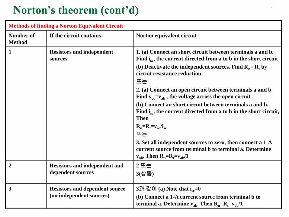
Norton’s theorem (cont’d)
Methods of finding a Norton Equivalent Circuit
Number of
Method
If the circuit contains: Norton equivalent circuit
1 Resistors and independent
sources
1. (a) Connect an short circuit between terminals a and b.
Find isc, the current directed from a to b in the short circuit
(b) Deactivate the independent sources. Find Rn= Rt by
circuit resistance reduction.
또는
2. (a) Connect an open circuit between terminals a and b.
Find voc=vab , the voltage across the open circuit
(b) Connect an short circuit between terminals a and b.
Find isc, the current directed from a to b in the short circuit,
Then
Rn=Rt=voc/isc
또는
3. Set all independent sources to zero, then connect a 1-A
current source from terminal b to terminal a. Determine
vab. Then Rn=Rt=vab/1
2 Resistors and independent and
dependent sources
2 또는
3(상동)
3 Resistors and dependent source
(no independent sources)
3과 같이 (a) Note that isc=0
(b) Connect a 1-A current source from terminal b to
terminal a. Determine vab. Then Rn=Rt=vab/1

Department of Electrical and Computer Engineering, SNU
Prof. SungJune Kim
Example 5.5-1 Norton Equivalent Circuit
Find the Norton equivalent circuit for the circuit of Figure 5.5-2

Department of Electrical and Computer Engineering, SNU
Prof. SungJune Kim
Solution
Aisc 125.1 32nt RR

Department of Electrical and Computer Engineering, SNU
Prof. SungJune Kim
Example) Norton Equivalent Circuit
Find the Norton equivalent circuit for the circuit of Figure 5.5-2

Department of Electrical and Computer Engineering, SNU
Prof. SungJune Kim
Solution
1. Deactivate the source and find Rn
Replacing the voltage source by a short circuit
2. Short circuit connected to output terminals
KCL at node a in Figure 5.5-3
3. Thus, Norton equivalent has
kRn 4
126
126
mA25.1,4 scn ikR
mA25.1
012
V15
sc
sc
i
ik

Department of Electrical and Computer Engineering, SNU
Prof. SungJune Kim
Consider the circuit A shown in Figure 5.6-1. The Thévenin equivalent
circuit is shown in Figure 5.6-2
We wish to find the value of load resistance RL such that maximum
power is delivered to it.
First, we need to find the power from
Since the current i is
We find that the power is
Maximum Power Transfer
Fig 5.6-1
Fig 5.6-2

Department of Electrical and Computer Engineering, SNU
Prof. SungJune Kim
Assuming that vs and Rt are fixed for a given source, the maximum
power is a function of RL.
To find the value of RL that maximizes the power, we use the
differential calculus to find where the derivative dp/dRL equals zero.
Taking the derivative, we obtain
The derivative is zero when
We find that the maximum power is
Maximum Power Transfer (cont’d)

Department of Electrical and Computer Engineering, SNU
Prof. SungJune Kim
We may also use Norton’s equivalent circuit to represent the circuit
A shown in Figure 5.6-1. The equivalent circuit is shown in Figure 5.6-4
The current i may be obtained to yield
Therefore the power p is
Using calculus, we can show that the maximum power occurs when
Then the maximum power delivered to the load is
Maximum Power Transfer (cont’d)

Department of Electrical and Computer Engineering, SNU
Prof. SungJune Kim
Power actually attained as RL varies in relation to Rt.
Maximum Power Transfer (cont’d)

Department of Electrical and Computer Engineering, SNU
Prof. SungJune Kim
Example 5.6-1 Maximum Power Transfer
Find the load resistance RL that will result in maximum power delivered
to the load for the circuit of Figure 5.6-5. Also determine the maximum
power delivered to the load resistor.

Department of Electrical and Computer Engineering, SNU
Prof. SungJune Kim
Solution
Disconnect the load resistor. The Thévenin
voltage source vt is
The Thévenin resistance Rt is
The Thévenin circuit connected to the load
resistor is shown in Figure 5.6-6. Maximum
power transfer is obtained when
Then the maximum power is
25tL RR
V150180180
150tv
25
15030
15030tR
W225254
)150(
4
22
max
L
s
R
vp
Fig. 5.6-5
Fig. 5.6-6

Department of Electrical and Computer Engineering, SNU
Prof. SungJune Kim
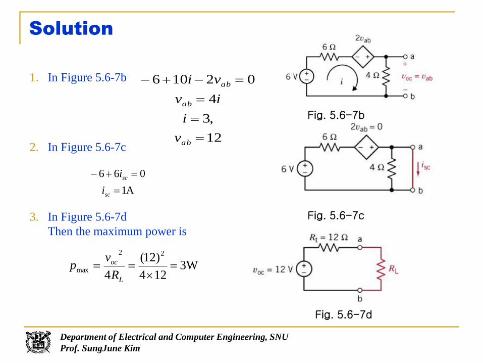
Example 5.6-2 Maximum Power Transfer
Find the load RL that will remain in maximum power delivered to the
load of the circuit of Figure 5.6-7a. Also determine pmax. delivered.
Department of Electrical and Computer Engineering, SNU
Prof. SungJune Kim
Solution
1. In Figure 5.6-7b
2. In Figure 5.6-7c
3. In Figure 5.6-7d
Then the maximum power is
12
,3
4
02106
ab
ab
ab
v
i
iv
vi
A1
066
sc
sc
i
i
W3124
)12(
4
22
max
L
oc
R
vp
Fig. 5.6-7b
Fig. 5.6-7c
Fig. 5.6-7d


