Download - CIVL 114 Civil Engineering Drawing Topic 7 Concrete blocks Setting lineweight and printing

CIVL 114CIVL 114Civil Engineering DrawingCivil Engineering Drawing
Topic 7Topic 7
Concrete blocks Concrete blocks
Setting lineweight and printingSetting lineweight and printing

OutlineOutline
Seawall blocks drawing Seawall blocks drawing – Front elevationFront elevation– Side elevationSide elevation
Before Printing Before Printing – Use a suitable linetype scaleUse a suitable linetype scale– Assign appropriate lineweightsAssign appropriate lineweights
Set up the plot detailsSet up the plot detailsReference readingReference readingHomeworkHomework

Seawall blocks drawingSeawall blocks drawing1350
500 500
800 800
2025
912.5
1012.5
2025
2700
KEY HOLES
200
TYPE M1

To draw the front elevationTo draw the front elevationFormat – Layer – Layer properties managerFormat – Layer – Layer properties manager
Prepare layers for center, hidden and dimension lines; uPrepare layers for center, hidden and dimension lines; use appropriatese appropriate linetypeslinetypes and and ltscaleltscale
Details of the icon
- refer to textbook
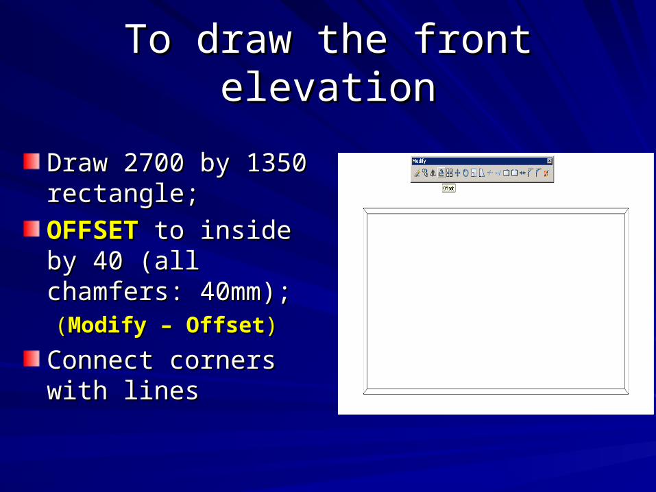
To draw the front elevationTo draw the front elevation
Draw 2700 by 1350 Draw 2700 by 1350 rectangle; rectangle;
OFFSETOFFSET to inside by 40 to inside by 40 (all chamfers: 40mm); (all chamfers: 40mm); ((Modify – OffsetModify – Offset))
Connect corners with Connect corners with lineslines

To draw the front elevationTo draw the front elevation
EXPLODEEXPLODE and and OFFSETOFFSET the left edge the left edge by 100 for the hole; by 100 for the hole; ((Modify – ExplodeModify – Explode))

To draw the front elevationTo draw the front elevationPut it on the Put it on the hidden line layerhidden line layerSet the linetype and linetype scale as follows:Set the linetype and linetype scale as follows:
1.1. Format – Linetype – Global scale factorFormat – Linetype – Global scale factor2.2. LTSCALE LTSCALE (short cut :(short cut : lts lts))

To draw the front elevationTo draw the front elevationTo draw the (left) center line: To draw the (left) center line: – try try LINE LINE – (use – (use FROMFROM snap mode; by Shift+Right click) – snap mode; by Shift+Right click) –
From BasepointFrom Basepoint: (pick top left corner): (pick top left corner)<Offset>: <Offset>: @ 800,0@ 800,0Specify next point: @ -300,-1350Specify next point: @ -300,-1350

To draw the front elevationTo draw the front elevation
Put it on the Put it on the center line layercenter line layer
SCALESCALE the center the center line by 1.2 line by 1.2 ((Modify – ScaleModify – Scale))
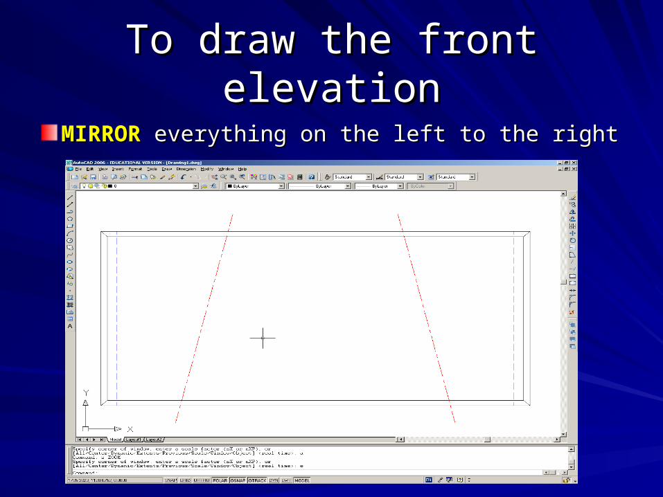
To draw the front elevationTo draw the front elevation
MIRRORMIRROR everything on the left to the right everything on the left to the right

To draw the side elevationTo draw the side elevationTurn on both Turn on both OSNAPOSNAP and and OTRACKOTRACK for for object trackingobject tracking
RECTANGRECTANGWithout clicking, touch Without clicking, touch the top right corner and the top right corner and move mouse to the right move mouse to the right (dashed line appears; (dashed line appears; see below)see below)
Enter 1000 (or other Enter 1000 (or other suitable separation)suitable separation)
Specify other corner Specify other corner point: @ 2025, -1350point: @ 2025, -1350

To draw the side elevationTo draw the side elevation
Modify - CHAMFERModify - CHAMFER – – specify both chamfer distances as 40specify both chamfer distances as 40
– – enter P (polyline option) – pick the rectangle enter P (polyline option) – pick the rectangle in side viewin side view
**CHAMFER: similar to FILLET but bevels **CHAMFER: similar to FILLET but bevels the edges rather than round them **the edges rather than round them **


Before Printing Before Printing Use a suitable linetype scaleUse a suitable linetype scale
1.1. Check your original drawing limits using the Check your original drawing limits using the LIMITS LIMITS command: they are from (0,0) to (a,b) command: they are from (0,0) to (a,b) (e.g. a = 12, b = 9) (e.g. a = 12, b = 9)
2.2. Check the dimensions (AxB) of your paper, in mm Check the dimensions (AxB) of your paper, in mm (e.g. 297x210 for A4 or 420x297 for A3 paper)(e.g. 297x210 for A4 or 420x297 for A3 paper)
3.3. What scale is to be used, 1:S What scale is to be used, 1:S (e.g. S = 50 for 1: 50 scale)(e.g. S = 50 for 1: 50 scale)
4.4. Approximately, the linetype scale should be (A/a)xSApproximately, the linetype scale should be (A/a)xS (e.g. 297/12x50). (e.g. 297/12x50). This is set in This is set in Format – Linetype ScaleFormat – Linetype Scale (for the (for the Global Global Scale FactorScale Factor))

Before PrintingBefore PrintingUse appropriate lineweightsUse appropriate lineweights
1.1. Choose Choose File – Plot Style ManagerFile – Plot Style Manager (the (the following table appears)following table appears)

Before PrintingBefore PrintingUse appropriate lineweightsUse appropriate lineweights
2.2. Double click Double click ““acad.ctb”acad.ctb” (a file which stores (a file which stores the lineweight the lineweight information by information by color) color) - click - click ““Form ViewForm View”” tab and the menu tab and the menu appears:appears:

Before PrintingBefore PrintingUse appropriate lineweightsUse appropriate lineweights
3.3. Select the color that you used for each line type Select the color that you used for each line type when creating the drawing. when creating the drawing. e.g. you may have used red (color 1) for all e.g. you may have used red (color 1) for all center lines; purple (color 6) for hidden lines, center lines; purple (color 6) for hidden lines, blue (color 5) for steel bars, black (color 7) for blue (color 5) for steel bars, black (color 7) for solid lines (title block and concrete outline, etc.).solid lines (title block and concrete outline, etc.).
4.4. Assign the appropriate Assign the appropriate lineweightlineweight for each color for each color
(e.g. 1mm for blue, 0.5 mm for black, etc.) – (e.g. 1mm for blue, 0.5 mm for black, etc.) – Save & CloseSave & Close..

Set up the plot detailsSet up the plot details
File – Page Setup ManagerFile – Page Setup Manager (the Page Setup Manager menu appears)(the Page Setup Manager menu appears)
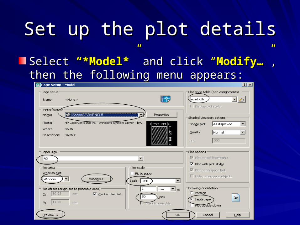
Set up the plot detailsSet up the plot details
Select Select “*Model*“*Model*”” and click and click ““Modify…Modify…””, then the , then the following menu appears:following menu appears:

Set up the plot detailsSet up the plot details1.1. For For Plot style tablePlot style table, choose , choose acad.ctb – Yes acad.ctb – Yes to use the lineweightes to use the lineweightes
you assignedyou assigned2.2. Choose Choose Printer/plotterPrinter/plotter (e.g. BarnCL5) and (e.g. BarnCL5) and Paper sizePaper size (usually A3) (usually A3)3.3. In In Plot AreaPlot Area, choose what to plot (e.g. by , choose what to plot (e.g. by windowwindow & choose corners & choose corners
of title block)of title block)4.4. Plot scale:Plot scale: 5.5. Check “Check “Fit to paperFit to paper” if scale is unimportant (e.g. just a rough draft)” if scale is unimportant (e.g. just a rough draft)6.6. If a scale is specified, then uncheck “If a scale is specified, then uncheck “Fit to paperFit to paper” ”
• Suppose scale is 1:50 (meaning: 1 mm on paper will represent 50 mm of Suppose scale is 1:50 (meaning: 1 mm on paper will represent 50 mm of actual object), while drawing dimensions are in mm. actual object), while drawing dimensions are in mm.
• Choose “1:50” directly or choose “Choose “1:50” directly or choose “CustomCustom” and set ” and set 1 mm1 mm (on paper) (on paper) = = 50 units50 units (on drawing) (on drawing)
7.7. In “In “Plot offsetPlot offset”, select “”, select “Center the plotCenter the plot””8.8. Always Always PreviewPreview: change the orientation to : change the orientation to PortraitPortrait or or LandscapeLandscape if if
needed (right-click - needed (right-click - ExitExit to exit preview). Click “ to exit preview). Click “OKOK” – “” – “CloseClose” if all ” if all is OK.is OK.

HomeworkHomeworkSurnameSurname Last digit of SID = Last digit of SID =
0/1/2/30/1/2/3Last digit of SID = Last digit of SID =
4/5/64/5/6Last digit of SID = Last digit of SID =
7/8/97/8/9
A - LawA - Law Types M1 & M2 Types M1 & M2 (Drawing no.: (Drawing no.:
1A)1A)
Types M2 & M3Types M2 & M3(Drawing no.: 1C)(Drawing no.: 1C)
Types M3 & M4Types M3 & M4(Drawing no.: 1E)(Drawing no.: 1E)
othersothers Types M1 & M4Types M1 & M4(Drawing no.: 1B)(Drawing no.: 1B)
Types M2 & M4Types M2 & M4(Drawing no.: 1D)(Drawing no.: 1D)
Types M1 & M3Types M1 & M3(Drawing no.: 1F)(Drawing no.: 1F)
Drawing title: SEAWALL CONCRETE BLOCKSDrawing title: SEAWALL CONCRETE BLOCKS
•Draw 1:1 (using the given dimensions in mm) on AutoCAD•Print at 1:50 scale on A3 paper (put both the two types of blocks on the same drawing)•Use proper lineweight as discussed in first lecture

HomeworkHomework
2700
800
10
12.5
20
25
13
50
500
800
TYPE M2
2025500
600 200 200 600

HomeworkHomework
3375
750200200750
162
0
135
0
1150
750
TYPE M3
1620
1150
750
KEY HOLES
810
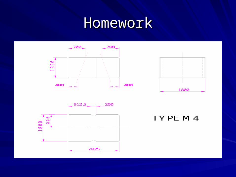
HomeworkHomework
TYPE M4
1800
700 700
13
50
400
18
00 90
0
2025
200912.5
400


