Download - ClearCam User Manual - Cobham
Page 1 Specifications subject to change without notice
ClearCam User Manual
Users’ Manual
Version 1.5 6th April 2010
Cobham Surveillance
Domo Products
11 Manor Court, Barnes Wallis Road, Segensworth, Hampshire, PO15 5TH, England
T: +44 (0)1489 566 750
F: +44 (0)1489 880 538

2
, 18th October 2004
1 Table of Contents
1 Table of Contents ................................. ......................................................... 2
2 List of Figures ................................... ............................................................. 3
3 List of Tables .................................... ............................................................. 3
4 Change History .................................... .......................................................... 4
5 About this Manual ................................. ......................................................... 5
6 Introduction....................................... ............................................................. 6
7 Warranty and Support .............................. ..................................................... 8
7.1 Warranty Cover ............................................................................................... 8
8 Safety and Approvals .............................. ...................................................... 9
8.1 Safe Operating Procedures ............................................................................. 9
8.2 EMC / Safety and Radio Approvals .................................................................. 9
8.3 CE marking .................................................................................................... 10
9 Getting Started and Basic Operation ............... .......................................... 11
9.1 Which Model Do I Have? ............................................................................... 11
9.2 Understanding the ClearCam ........................................................................ 12
9.3 Basic Operation ............................................................................................. 13
10 Advanced Operation ................................ .................................................... 18
10.1 Battery Management with Sleep Modes ..................................................... 18
10.2 Connecting the PC Controller ..................................................................... 19
10.3 ClearCam Control Application: Transmitter Settings ................................... 20
10.4 ClearCam Control Application: Telemetry Receiver Settings ...................... 28
10.5 ClearCam control application: System settings ........................................... 32
10.6 MicroVue Commander Basic Operation ...................................................... 34
11 Fault Finding ..................................... ........................................................... 40
11.1 RF and Audio / Video ................................................................................. 40
12 Connector Pin Outs ................................ ..................................................... 42
12.1 Power: 2-pin Amphenol (62GB-12E10-02SN) ............................................. 42
12.2 RS232 PC Control: 3-pin Amphenol (62GB-12E08-03SN) .......................... 42
12.3 Sensor: 8-pin Amphenol (62GB-12E12-08SN) ........................................... 42
12.4 Audio in/out: 6-pin Amphenol (62GB-12E10-06SN) .................................... 43
12.5 Camera: 14-pin Amphenol (62GB-12E12-14SN) ........................................ 43
13 Control Protocols ................................. ....................................................... 44
13.1 RS232 Control – General Principles ........................................................... 44
13.2 Packet Structure Sending (from PC) ........................................................... 44
13.3 Packet Structure Reply (from controlled device) ......................................... 45
13.4 Receiver Command List ............................................................................. 46
14 Default Configurations ............................ .................................................... 49
14.1 SOL4CLCP-240045 (PAL, S-Band Video, 458MHz Telemetry) .................. 49
14.2 SOL4CLCP-240086 (PAL, S-Band Video, 868MHz Telemetry) .................. 50
14.3 SOL4CLCN-240090 (NTSC, S-Band Video, 903MHz Telemetry) ............... 50
14.4 Common Default Settings ........................................................................... 51
14.5 Loading Config Sets ................................................................................... 53
15 Technical specifications .......................... ................................................... 55
15.1 ClearCam Specification .............................................................................. 55
15.2 Telemetry Bandwidths and Bitrates ............................................................ 57
3
2 List of Figures
Figure 1 ClearCam ......................................................................................... 12
Figure 2 ClearCam user interface .................................................................. 14
Figure 3 ClearCam connector panel ............................................................. 16
Figure 4 PC control application, Transmitter window ................................... 20
Figure 5 PC control application, Advanced transmitter settings .................. 22
Figure 6 PC control application, Receiver window ....................................... 28
Figure 7 PC control application, Advanced receiver settings ....................... 29
Figure 8 PC control application, System settings ......................................... 33
Figure 9 Front view of the MicroVue lid ......................................................... 34
Figure 10 Top view of the MicroVue Commander base (no DVR fitted) ...... 34
Figure 11 Rear view of MicroVue with external connector cabinet ............... 35
Figure 12 Commander PTZ camera control panel ....................................... 35
Figure 13 Commander and ClearCam control address illustration............... 37
Figure 14 ClearCam status and control page ................................................ 38
3 List of Tables
Table 1 ClearCam product codes .................................................................. 11
Table 2 ClearCam user interface ................................................................... 14
Table 3 MicroVue Commander switch panel functions ................................. 36
Table 4 ClearCam status screen ................................................................... 38
Table 5 ClearCam sleep modes .................................................................... 39
Table 6 SOL4CLCP-240045 Video Frequency Settings .............................. 49
Table 7 SOL4CLCP-240045 Telemetry Frequency Settings....................... 49
Table 8 SOL4CLCP-240086 Video Frequency Settings .............................. 50
Table 9 SOL4CLCP-240086 Telemetry Frequency Settings....................... 50
Table 10 SOL4CLCN-240090 Video Frequency Settings ............................ 50
Table 11 SOL4CLCN-240090 Telemetry Frequency Settings ..................... 50
Table 12 Video Transmitter Basic Settings .................................................... 51
Table 13 Video Transmitter Advanced Settings ............................................ 51
Table 14 Telemetry Receiver Basic Settings ................................................. 52
Table 15 System Settings ............................................................................... 52
Table 16 MicroVue Commander Settings ...................................................... 52

4
4 Change History
Version
Main Changes from Previous Version
Edited By
v1.0 Initial Release NH
v1.1 Add EMC and safety approvals NMcS
v1.2 Added Flat battery note and added more detail on default configurations
NMcS
v1.3 Sleep mode info added, Config set info added, general editing
NH
V1.4 Changed Front page? PB Digital?
V1.5 Corrected 458MHz telemetry receiver range NMcS
5
5 About this Manual
This manual describes the operation of the domo ClearCam. The manual is divided into three main sections.
• Getting started and basic operation
This section describes to users how to deploy and use a domo ClearCam system.
• Advanced operation
This section describes the operation of the system in more detail, concentrating particularly on Setup and Configuration.
• Technical reference
This section provides technical specification and control protocol data and will be of interest to those integrating the ClearCam into larger systems.

6
6 Introduction
The domo ClearCam is a tactical digital video transmitter system and is part of the domo SOLO4 and SOLO2 product family. The SOLO4 and SOLO2 product range enables the user to build simple wireless digital microwave video systems. The domo SOLO4 and SOLO2 products have been designed to provide rugged point-to-point links for high quality full frame rate video, and audio, even in non line of sight and urban environments.
Existing analogue systems suffer from impairments such as video noise, loss of colour information and poor image quality when line of sight cannot be maintained. PC platforms and solutions based on wireless internet standards including WiFi deliver poor quality video, as well as poor range capability.
The domo SOLO4 and SOLO2 system is a digital system that uses the COFDM modulation technique, which effectively eliminates the problems caused by multipath and reflections.
The SOLO product range allows law enforcement, surveillance and emergency service communities to now receive the highest quality video images, in real time, direct from personnel, buildings and vehicles.
The domo SOLO2 system employs the DVB-T 2K carrier COFDM technology.
The domo SOLO4 system employs a revolutionary narrow band 2.5MHz COFDM technology which demonstrates better propagation for longer range links, and extra bandwidth efficiency. The domo SOLO4 system can also be upgraded to include a 1.25MHz COFDM modulation and MPEG4 compression for excellent range performance.
The ClearCam is a rugged PTZ camera designed specifically for rapid deployment. The system incorporates a periscope camera, digital video transmitter, telemetry receiver and battery technology inside a weatherproof package for long term outdoor deployment.
The ClearCam is used in conjunction with the MicroVue Commander to provide a complete digital surveillance link. The ClearCam differs from other domo Solo4Tx products in its return control channel built into the system.
The ClearCam chassis is designed with the intent of meeting IP66 and supplied with a variety of mounting options. The integral periscope camera can be detached from the base for maximum deployment flexibility. It is supplied with DC and internal battery power.
The domo narrow bandwidth modulation offers unprecedented spectrum efficiency, while also increasing the system sensitivity and therefore range.
Security of transmission is ensured by the use of Standard ABS encryption or for greater security the optional AES128- or 256-bit encryption algorithms.
For detail on the MicroVue Commander operation, please refer to the ‘MicroVue and MicroVue Commander User Manual’.
7
Features:
• Two-way communication
• Rugged weatherproof chassis
• Integrated PTZ periscope camera, digital video transmitter, telemetry control and battery
• Sophisticated sleep and wake up options for battery life extension
• External sensor trigger input
• Audio in/out
• External DC input for long duration deployments
• 36x optical zoom, 12x digital zoom
• 400° pan, +20° to -40° tilt
• Secure communication
IMPORTANT NOTE
The domo ClearCam has been specifically designed for government security and law
enforcement users, the equipment will tune across frequencies that are only available to
licensed government users. Non-government users should employ the equipment
restricted to the license exempt bands only typically 1.389 to 1.399GHz and 2.400 to
2.483GHz.

8
7 Warranty and Support
7.1 Warranty Cover
domo offers a 12 month standard product warranty. During this period, should the customer encounter a fault with the equipment we recommend the following course of action:
• Check the support section of the website for information on that product and any software/firmware upgrades. If fault persists;
• Call our support line and report the fault. If fault persists and you are informed to return the product please obtain an RMA number from the domo support department, and ship the equipment with the RMA number displayed and a description of the fault. Please email the support section the airway bill/consignment number for tracking purposes.
• If you have extended warranty provisions then domo will send an immediate advance replacement to you. Under most circumstances this must be returned once the fault item is repaired.
Depending on the nature of the fault domo endeavor to repair the equipment and return it to the customer within 14 days of the item arriving at our workshops.
Obviously it is impossible to cater for all types of faults and to manage 100% replacement part availability, and delays are sometimes inevitable. This is why domo recommend that its customers take out an extended warranty (which includes advanced replacement of faulty items), and/or hold a basic level of spare parts, which can be held by domo on the customer’s behalf.
Please contact domo for details of packages that can be tailored to meet your individual needs, whether they are service availability, technical training, local geographic support or dedicated spares holdings.

9
8 Safety and Approvals
8.1 Safe Operating Procedures
• Ensure that the power supply arrangements are adequate to meet the stated requirements of the product.
Caution: When using the DC input ensure the DC supply is capable of 12V at 8A.
Caution: Risk of explosion if battery is replaced by an inappropriate type. Battery
replacement can only be undertaken by domo personnel who will also ensure safe battery
disposal.
• Operate within the environmental limits specified for the product.
• Only authorized, trained personnel should open the product. There are no functions that require the user to gain access to the interior of the product.
8.2 EMC / Safety and Radio Approvals
The equipment has been designed to meet and has been tested against the following harmonized EMC and safety standards:
• EN 301 489-1 & EN 301 489-5
• EN 61000-3-2:2000
• EN 61000-3-3:1995
• EN 55022:1998, Class B
• EN 61000-4-2:1995
• EN 61000-4-3:1996
• EN 61000-4-4:1995
• EN 61000-4-5:1995
• EN 61000-4-6:1996
• EN 61000-4-11:1994
• EN 60950:2000

10
8.3 CE marking
The CE mark is affixed to all SOLO4 and SOLO2 products, and the CE Declaration of Conformity, as well as the technical file are available on request.
11
9 Getting Started and Basic Operation
9.1 Which Model Do I Have?
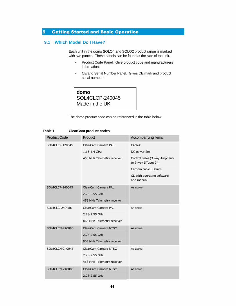
Each unit in the domo SOLO4 and SOLO2 product range is marked with two panels. These panels can be found at the side of the unit.
• Product Code Panel. Give product code and manufacturers information.
• CE and Serial Number Panel. Gives CE mark and product serial number.
The domo product code can be referenced in the table below.
Table 1 ClearCam product codes
Product Code Product Accompanying items
SOL4CLCP-120045 ClearCam Camera PAL
1.15-1.4 GHz
458 MHz Telemetry receiver
Cables:
DC power 2m
Control cable (3 way Amphenol
to 9 way DType) 3m
Camera cable 300mm
CD with operating software
and manual
SOL4CLCP-240045 ClearCam Camera PAL
2.28-2.55 GHz
458 MHz Telemetry receiver
As above
SOL4CLCP240086 ClearCam Camera PAL
2.28-2.55 GHz
868 MHz Telemetry receiver
As above
SOL4CLCN-240090 ClearCam Camera NTSC
2.28-2.55 GHz
903 MHz Telemetry receiver
As above
SOL4CLCN-240045 ClearCam Camera NTSC
2.28-2.55 GHz
458 MHz Telemetry receiver
As above
SOL4CLCN-240086 ClearCam Camera NTSC
2.28-2.55 GHz
As above
domo SOL4CLCP-240045 Made in the UK

12
868 MHz Telemetry receiver
SOL4CLC-PSU 12V 8A Mains to DC
universal power supply unit
n/a
CABCLCCAM ClearCam camera extension
cable
Length 3m
n/a
Note: Check telemetry frequency options available in end user country prior to
order.
9.2 Understanding the ClearCam
The domo ClearCam is a rugged PTZ camera and microwave transmitter incorporating the following principle components.
• Weatherproof chassis
• PTZ periscope camera
• COFDM digital video transmitter
• Telemetry receiver for PTZ commands
• Integral DC and Battery power supply
• Status screen
• Detachable camera base with mounting holes for flexible deployment options
The principle components are highlighted in the photograph below.
Figure 1 ClearCam
Telemetry receive antenna
Periscope camera
Video transmit antenna
Detachable Camera base
Base
Weatherproof connectors

13
9.3 Basic Operation
Powering on the domo ClearCam
The ClearCam has two power supply options
• Internal Batteries
• External DC Input
The unit is powered on by latching the green master power switch into the depressed ON position. The status screen will briefly display the domo logo if power is On and there is power remaining in the batteries. Note that if the battery is completely exhausted the screen will not light.
Internal Batteries
The ClearCam will automatically switch to using the internal battery supply when the DC input is not connected to a valid supply.
The internal batteries are charged automatically when a valid supply is connected to the external DC input.
Fully charged batteries will power the ClearCam for about 7h30min in continuous 100mW mode, and 3h40min in continuous 1W mode.
The battery life can be extended by employing the Sleep Mode options of the unit. See paragraph ‘Sleep modes’ for more information.
See the paragraph ‘Charging the domo ClearCam’ for charging information.
External DC Input
The domo ClearCam can be powered from an external DC source such as a battery, by connecting the DC connector in the external connector cabinet to a DC source with the following characteristics.
Voltage: 11 to 16V
Current: max (when charging) 6A (at 12V)
Typical (when charged) 3A (at 12V)
Charging the domo ClearCam
The domo ClearCam internal batteries are automatically charged when the unit is connected to an external DC source.
The time required to fully charge the batteries from fully flat is as follows.
Charging when ClearCam powered off: Approximately 1.5 hours
Charging when ClearCam powered on: Approximately 3 hours
Note: When the Clearcam has exhausted the battery and a new power source, such as a new battery the POWER switch MUST be switched OFF and ON to restart the unit.
This requirement stops the unit ‘cycling’ on and off when the battery is approaching a flat condition.

14
Understanding the user interface
There are five buttons on the front of the ClearCam, as shown in the figures below. The functionality is outlined in Table 2.
Figure 2 ClearCam user interface
Table 2 ClearCam user interface
Button Function
Status
Pressing this button gives the user access to the general status
information of the unit. The following parameters will be displayed
in order:
• Config: Config number currently loaded from memory.
Eight configurations can be stored in the unit’s memory.
• Battery life: Estimated remaining battery life of
ClearCam
• Link in: Frequency and link quality of ClearCam telemetry
receiver. The link status is rated on a five star basis. 0
stars = no link; 5 stars = excellent link.
• Link out: Frequency and link quality of the ClearCam
video transmitter.
The link status is rated on a five star basis. 0 stars = no
link; 5 stars = excellent link. (See Note 1)
Also indicates power level of the transmitter as Off /
100mW / 1W.
• Trigger: Trigger count of the external sensor.
• Software version
Config
Pressing this button increments the configuration number and loads
that config from memory. The new config number is briefly
displayed on the status screen.
Channel
This button displays the channel number of the unit (default is 15).
This number should agree with the Control Address on the
MicroVue Commander in order for the ClearCam to accept PTZ
commands. (See Note 2)
Power
RF
Status
Config
Channel

15
Power Latching button to switch the unit ON in its depressed state, and
OFF in its released state.
RF Cycles the unit output power through Off / 100mW / 1W. Current
power level is briefly displayed on the screen as the button is
pressed.
Note 1: The Status information related to Link Out is sent via the telemetry link into ClearCam. Hence, with no link in, no status information is available about the Link Out.
Note 2: It is possible to control up to 15 different cameras with one MicroVue Commander. To facilitate this, the ClearCam only accepts PTZ commands if the Camera Control Address number is the same as on the Commander. See Section ‘MicroVue Commander Basic Operation’ for more information.
Changing Configuration on the domo ClearCam
The ClearCam contains both a video transmitter and telemetry receiver.
To simplify the operation of the domo ClearCam, users can pre-program eight ‘User Configurations’ for both the ClearCam transmitter and receiver. In their simplest form these can be thought of in the traditional sense as eight frequency channels. However, the User Configurations actually store all the parameters of the ClearCam and not just its frequency.
When changing the ClearCam config as described in Table 2, both the transmitter and receiver confgs are changed at the same time.
The currently loaded User Configuration can be viewed by pressing the STATUS button.
The default User Configurations (values of parameters which the units are shipped with) are described in Section 14 at the end of the user guide.
See the advanced Section 10 of the user guide for more information on how to edit the parameters inside the user configurations.
Deploying and Operating the domo ClearCam
The domo ClearCam is a tactical digital video transmitter, and the following guidelines should be employed when using the equipment.
• Connect the L- or S-band transmit antenna (TNC connector) to RF OUT, and UHF receive antenna (BNC connector) to RF IN on the base of the ClearCam.
• Connect the Camera to the base via the camera cable. Note the genders on the cable.
• Either coil the short camera cable into the camera base and slot the camera base into the chassis, or mount it elsewhere with the long camera cable.
16
• Connect the telemetry transmit antenna to the SMA connector on the lid of the MicroVue Commander.
• Switch on both the ClearCam and MicroVue Commander and make sure they are on the same config.
• Depending on the RF environment (line of sight or non line of sight) and the power of the transmitter (100mW or 1W), the ClearCam will operate at a range typically 300m to 1km from the Commander.
• To prevent damage to the MicroVue Commander, it should not be operated too close (within 5m typically, further if the ClearCam is transmitting 1W in power) of the ClearCam.
Note: Connect antennas BEFORE powering on unit.
Damage may occur if the transmitter drives 1W output power into no load
External Connections on the domo ClearCam
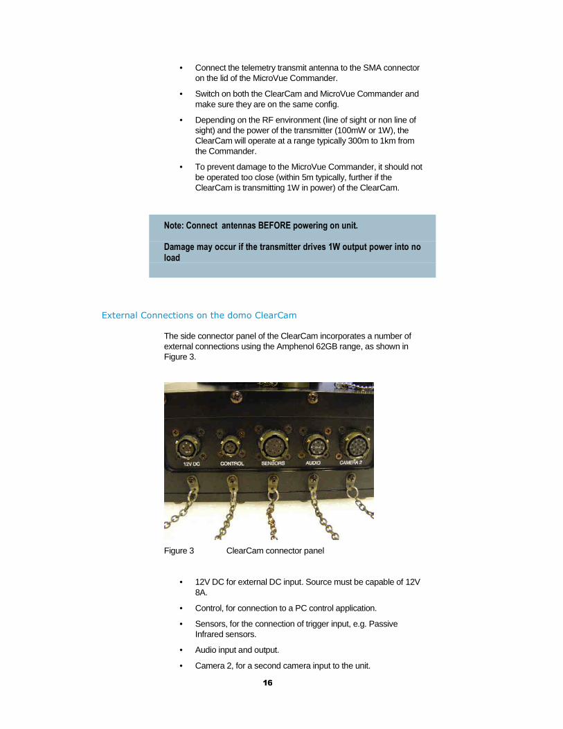
The side connector panel of the ClearCam incorporates a number of external connections using the Amphenol 62GB range, as shown in Figure 3.
Figure 3 ClearCam connector panel
• 12V DC for external DC input. Source must be capable of 12V 8A.
• Control, for connection to a PC control application.
• Sensors, for the connection of trigger input, e.g. Passive Infrared sensors.
• Audio input and output.
• Camera 2, for a second camera input to the unit.
17
These connectors are completely waterproof when mated with their cables or the supplied dust caps. However, they are not waterproof when unmated as in Figure 3.
The cables supplied with the unit include a 12V DC power cable and PC control cable.
The connector part numbers and pin-outs are supplied in the section ‘Connector Pin Outs’.
Connecting to PC Control
The domo ClearCam can be controlled from a PC with the domo Control Application, via RS-232.
Connect a domo control cable to any serial port on the PC and plug the Amphenol connector into the side of the ClearCam. Start the PC control application.
It should now connect to the unit while saying “Reading transmitter settings” and “Reading receiver settings”, enabling the user to edit these parameters. See the ‘Control Protocol’ section for details of the protocol, baud rates etc.
18
10 Advanced Operation
The following section should be read by users concerned with the more advanced operation of the domo MicroVue. Topics covered include:
• Battery management with sleep modes
• Connecting the PC Controller.
10.1 Battery Management with Sleep Modes
The battery life of the ClearCam is about 3h40min in continuous 1W mode, and 7h30min in continuous 100mW mode. This can be extended through the use of sleep modes and sleep timeouts.
Sleep mode 1
When the unit is put into Sleep mode 1, the video transmitter will be switched into standby mode after a set number of minutes of trigger inactivity. This drops the power consumption to 34% of the power needed in continuous 100mW mode.
The unit can be woken up from Sleep mode 1 by a trigger event, by remotely setting sleep to OFF on the MicroVue Commander, or by setting sleep to OFF on the PC control application.
Sleep mode 2
When the unit is put into Sleep mode 2, both the video transmitter and telemetry receiver will be switched into standby mode after a set number of minutes of trigger inactivity. This drops the power consumption to 18% of the power needed in continuous 100mW mode and provides the longest possible battery life.
The unit can be woken up from Sleep mode 2 by a trigger event, or by setting sleep to OFF in the PC control application. NOTE: The MicroVue Commander can not be used to wake a unit up from Sleep mode 2 remotely.
Sleep timeout
The number of minutes of no trigger activity before sleep timeout is set in the PC control application and can be in the range of 1 to 9 minutes.
Wake up
Upon the occurance of trigger activity, or by setting Sleep mode to OFF in the PC control application, the ClearCam will wake up both the transmitter and receiver.
Wake up time is approximately 4 seconds.
See the section ’ ClearCam control application: System settings’ for how to set up the sleep modes on the PC control application.
19
10.2 Connecting the PC Controller
Advanced control of the ClearCam system is available by using the PC control application. This can be achieved by connecting a PC RS-232 port to the 3-pin Amphenol control port.
Connecting to the PC
Installation of the control program is as simple as copying it from the CD to a suitable location on the PC. No install shield routine is launched. Note that the controllers generate their own log and initialisation files, so it is best to create a dedicated directory for these applications, perhaps with links to the applications from the desktop of the PC.
Use the supplied cables to connect the chosen COM port(s) of the PC to unit(s) to be configured.
Launch each application in turn by double clicking or using the run command.
Connection with a SOLO product should be automatic, but the user can force selection of the correct COM port using the drop down, followed by the “Connect” button.
Errors such as the following may appear during the connection process if the PC is unable to automatically ascertain which unit is connected to which COM port.
• Error attempting to read invalid address
• Error has occurred during polling, polling has been disabled
For both controllers, changes can be made to the unit configuration using the drop down and data entry fields.
Changes are only applied to the unit when the “Apply” button is clicked.
Current values, as running in the unit, can be read using the “Refresh” button.
Parameters that are status information only appear in greyed in the application.
Further engineering and configuration controls can be found within the “Options” and “File” drop down menus in the application title bars.
Understanding configs and how to modify them
domo ClearCam features eight user selectable and programmable configurations, relating to both the transmitter and receiver in the unit.
The transmitter and receiver have separate tabs and are set up individually as shown in
Figure 4, each having 8 configs.
These 8 configs allow the user to store useful default channels for quick selection. After restoring defaults and loading the supplied config set, all 8 configurations are set to the values which are listed in the Section 14 of the handbook.

20
The current config is defined as the number of the currently selected configuration 1 to 8. The current config can be changed by selecting a different config tab.
Upon exiting the control application, the transmitter is set to the same config number as the receiver. Further, loading a config on ClearCam with the CONFIG button will load that config number on both the transmitter and receiver.
10.3 ClearCam Control Application: Transmitter Sett ings
Figure 4 PC control application, Transmitter window
Engineering Menu
Polling Enable
Enter Encryption Key
Enter a Licence key
Restore Factory Defaults
Connectivity Status
Video alarm RF Output status
Current selected Config
All parameter changes must be applied

21
The ‘Advanced’ button allows the user to navigate to the controller page which exposes all available Transmitter settings.
Output Frequency (MHz)
The transmit frequency can be changed by entering the new desired frequency in this field. Values outside the range supported by a particular transmitter type will be rounded to the highest of lowest supported frequency as appropriate.
The transmit frequency can be set in step sizes of 250kHz.
Bandwidth Mode
The Bandwidth Mode switches the unit between either domo Narrowband (2.5MHz or 1.25MHz channel bandwidths) or DVB-T 8MHz bandwidth. To select 6MHz and 7MHz DVB-T modes the user must first click on ‘Advanced’ to enter the Advanced setting page.
Default Transmit Mode
In Narrowband the user has the following pre-defined modes available from the main window. Note that the Ultra Long Range Mode is only available to users who have purchased the SOLO4TXUP option (1.25MHz and MPEG-4 modes). The user can of course define their own specific FEC, bandwidth and modulation requirements from the ‘Advanced’ page.
Ultra Long Range: 1.25MHz QPSK FEC 1/3 (optional)
Long Range: 2.5MHz QPSK FEC 1/3
Medium Range: 2.5MHz QPSK FEC 2/3
Short Range: 2.5MHz 16QAM FEC 2/3
In DVB-T the available modes are
QPSK ½ FEC 8MHz 1/32 Guard Interval
QPSK ¾ FEC 8MHz 1/32 Guard Interval
16QAM ½ FEC 8MHz 1/32 Guard Interval
Audio
Turns ‘On’ or ‘Off’ a basic audio setting – the audio settings are optimised considering the bit-rate of the selected Transmit mode. The user can set their own audio settings using the ‘Advanced’ page, if required.
Scrambling
If the AES scrambling option has been purchased for the SOLO2 or SOLO4 system in use, then it is possible to encrypt the link. Scrambling must be enabled at the transmitter by selecting either AES128 or AES
22
256 in the scrambling field. The actual scrambling key can then be entered by clicking on the yellow ‘key’ icon.
Output status
This field indicates whether the transmitter is turned off, transmitting 100mW output power, or transmitting 1W output power.
File Options
Load Config – used for loading a single configuration data from text file.
Save Config - used for saving configuration data to text file.
Load Config Set – used for loading all 8 configurations from a text file
Save Config Set - used for saving all 8 configurations to a text file
Advanced TX Controller Window
`
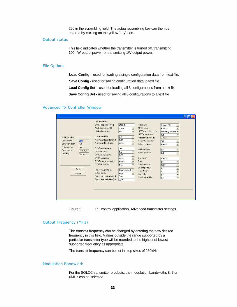
Figure 5 PC control application, Advanced transmitter settings
Output Frequency (MHz)
The transmit frequency can be changed by entering the new desired frequency in this field. Values outside the range supported by a particular transmitter type will be rounded to the highest of lowest supported frequency as appropriate.
The transmit frequency can be set in step sizes of 250kHz.
Modulation Bandwidth
For the SOLO2 transmitter products, the modulation bandwidths 8, 7 or 6MHz can be selected.
23
For the SOLO4 transmitter products, the modulation bandwidths 8, 7, 6 or 2.5MHz can be selected. If the Ultra Narrow band upgrade has been purchased the 1.25MHz will also be available to select.
The normal mode of operation is 2.5MHz.
Modulation Output
This control is used to turn on and off the RF output.
Narrow Band FEC
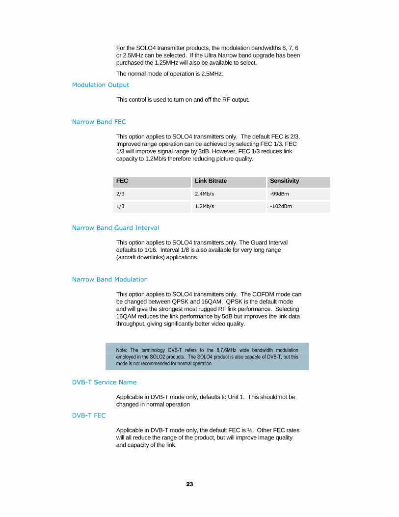
This option applies to SOLO4 transmitters only. The default FEC is 2/3. Improved range operation can be achieved by selecting FEC 1/3. FEC 1/3 will improve signal range by 3dB. However, FEC 1/3 reduces link capacity to 1.2Mb/s therefore reducing picture quality.
FEC Link Bitrate Sensitivity
2/3 2.4Mb/s -99dBm
1/3 1.2Mb/s -102dBm
Narrow Band Guard Interval
This option applies to SOLO4 transmitters only. The Guard Interval defaults to 1/16. Interval 1/8 is also available for very long range (aircraft downlinks) applications.
Narrow Band Modulation
This option applies to SOLO4 transmitters only. The COFDM mode can be changed between QPSK and 16QAM. QPSK is the default mode and will give the strongest most rugged RF link performance. Selecting 16QAM reduces the link performance by 5dB but improves the link data throughput, giving significantly better video quality.
Note: The terminology DVB-T refers to the 8,7,6MHz wide bandwidth modulation
employed in the SOLO2 products. The SOLO4 product is also capable of DVB-T, but this
mode is not recommended for normal operation
DVB-T Service Name
Applicable in DVB-T mode only, defaults to Unit 1. This should not be changed in normal operation
DVB-T FEC
Applicable in DVB-T mode only, the default FEC is ½. Other FEC rates will all reduce the range of the product, but will improve image quality and capacity of the link.
24
DVB-T Guard Interval
Applicable in DVB-T mode only. The Guard Interval defaults to 1/32. Other guard intervals such as 1/16 or 1/8 are available for very long range (aircraft downlinks) applications.
DVB-T Modulation
Applicable in DVB-T mode only, the COFDM mode can be changed between QPSK, 16QAM and 64QAM. QPSK is the default mode and will give the strongest most rugged RF link performance. Selecting 16QAM reduces the link performance by 5dB but improves the link data throughput, giving significantly better video quality.
Output Attenuation
This control can be used to make minor adjustments to the output power level, but in normal operation should be disregarded.
Video Input
This control is used to select the video input standard. Options are composite video (PAL, and NTSC both with and without 7.5 IRE pedestal), S-video (PAL and NTSC) and SDI (not applicable to ClearCam).
MPEG Mode
The default encoding mode is MPEG2, however for SOLO4 products if the Ultra Narrow Band upgrade has been purchased, then MPEG4 will also be available. It is recommended that MPEG4 be employed when the unit is operating at low bitrates (2.5MHz bandwidth FEC1/3 or 1.25MHz bandwidth FEC1/3).
MPEG4 Encoding Mode
This option is only available on SOLO4 products installed with the Ultra Narrow Band Upgrade. This defaults to low delay interlace. Other modes are available but advice should be sought from domo before selection.
MPEG4 Frame Rate
This option is only available on SOLO4 products installed with the Ultra Narrow Band Upgrade. This option allows the user to select lower frame rate encoding (1/2 frame rate, ¼, 1/8 etc) It is recommended that MPEG4 reduced frame rates be employed when the unit is operating at low bitrates (1.25MHz bandwidth FEC1/3).

25
Horizontal resolution
The video coding resolution can be selected from 704, 528, 480 and 352 pixels. Changing the horizontal resolution to lower values will make the coded picture softer.
Care should be taken to match the horizontal resolution to the resolution of the camera connected to the transmitter; this will give best image results.
Audio Encoder
The Audio can be turned on and off with this control. Audio is OFF by default, but there are several audio modes that vary from very high quality to speech grade that can be selected with this control. Enabling audio will degrade the video quality, because some of the available data capacity is diverted away from video to audio. Selecting high fidelity audio modes will degrade the video quality more than lower fidelity audio modes.
Audio Input Level
This control is used to define the audio gain to be applied to the audio input signal. 0dB is used for line level audio and various options up to 48dB of gain can be applied for microphone inputs.
Unit Name
This field allows the user to enter an identifier for the service that they wish to transmit. This must match that selected at the receiver for the service to be decoded. The unit name can be constructed of any eight ASCII characters.
Data
With this ON / OFF control the user can select whether the transmitter passes serial RS232 data across the RF link to the receiver.
Data Baud Rate
This field is used to select the baud rate of any RS232 serial data component to be passed from the transmitter to the receiver across the RF link.
Current Config
This field reports the last loaded configuration number. Note that for the SOLO transmitter, changes applied after the configuration has been loaded are saved immediately into the current configuration.

26
Scrambling
If the AES scrambling option has been purchased for the SOLO2 or SOLO4 system in use, then it is possible to encrypt the link. Scrambling must be enabled at the transmitter by selecting either AES128 or AES 256 in the scrambling field. At this point the user will need to ensure that the correct key is in use and this is done by using Options / Write AES Key.
The key is a 128bit key for AES128 and a 256bit key for AES256 and is entered as either 32 or 64 ASCII hexadecimal characters (0..F).
Video Locked (Status Only)
This status information indicated whether the transmitter is successfully locked to the incoming composite video signal. Unlocked status may indicate cabling faults, or poor quality incoming video feeds to the unit.
Software Version (Status Only)
This status information describes the version of the software running the SOLO transmitter product.
FPGA Version (Status Only)
This information is for domo engineering use only.
Serial Number (Status Only)
This status information is the electronic serial number of the transmitter PCB. This number can be exchanged with domo to purchase extra licensable features, such as upgrades to support AES encryption.
Chaining (Status Only)
This field reports the status of the chaining input to the SOLO transmitter, and is not active in current units.
Options
Engineering – provides access to further diagnostic and calibration features. The Diagnostic and Power calibration pages must not be altered. The Advanced Options under the Engineering menu allow the user to Change RS232 address , which can be useful when connecting multiple units together via a multi drop RS485 bus for control purposes. The Serial control dialogue box allows the user to change timeouts used during the serial communications between the unit and the controller.
Enable Polling – selecting this option makes the control application automatically refresh the data presented to the user every few seconds.
Polling Options – selecting this option allows the user to define parameters to be regularly polled.

27
Write Encryption Key – opens a dialogue box for entering an ABS or AES scrambling key, as 32 ASCII hexadecimal characters (0…F)
Write License Code – open a further box for entering license codes for the activation of licensable features (e.g. AES scrambling) in the transmitter. Contact domo for support in applying new licenses as required.
Restore Defaults – restores factory default settings in the transmitter.
File
Set Icon Source, Set logo source, Set logo size and Set application title – allow the user to define a controller branding
Exit – exits the SOLO receiver control application
28
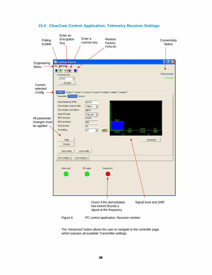
10.4 ClearCam Control Application: Telemetry Receiv er Settings
Figure 6 PC control application, Receiver window
The ‘Advanced’ button allows the user to navigate to the controller page which exposes all available Transmitter settings.
Engineering Menu
Polling Enable
Enter an Encryption Key
Enter a Licence key
Restore Factory Defaults
Connectivity Status
Green if the demodulator has locked (found) a signal at the frequency
All parameter changes must be applied
Current selected Config
Signal level and SNR
29
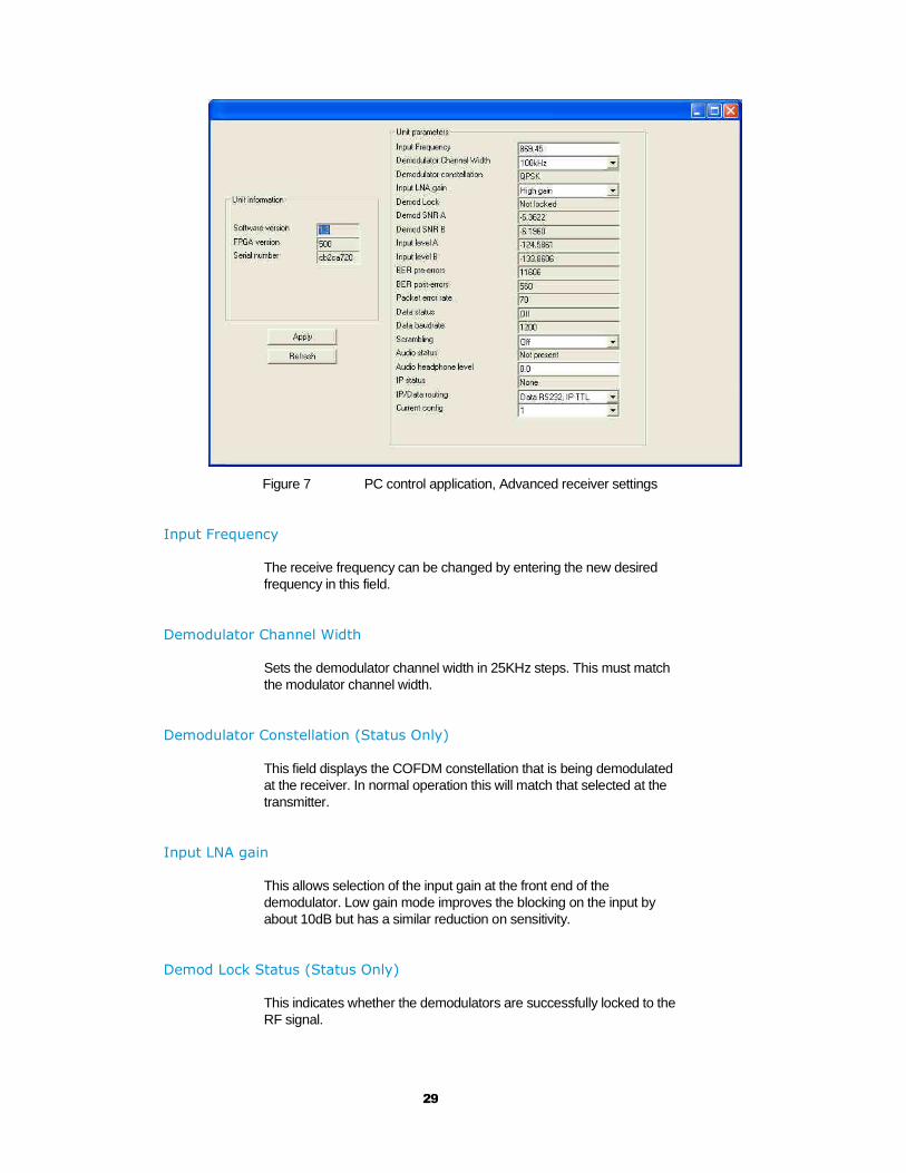
Figure 7 PC control application, Advanced receiver settings
Input Frequency
The receive frequency can be changed by entering the new desired frequency in this field.
Demodulator Channel Width
Sets the demodulator channel width in 25KHz steps. This must match the modulator channel width.
Demodulator Constellation (Status Only)
This field displays the COFDM constellation that is being demodulated at the receiver. In normal operation this will match that selected at the transmitter.
Input LNA gain
This allows selection of the input gain at the front end of the demodulator. Low gain mode improves the blocking on the input by about 10dB but has a similar reduction on sensitivity.
Demod Lock Status (Status Only)
This indicates whether the demodulators are successfully locked to the RF signal.

30
Input SNR (Status Only)
For each IF input, the SNR (Signal to Noise Ratio) is reported. Values in the order of 18dB to 22dB represent strong received signals, whilst values in the order of 5dB represent poor received signals which will likely give rise to decoding errors.
Input Level (Status Only)
This figure indicates the received signal level at the two receiver inputs. Normal Operation will occur when the input level is between –25 and –115 dBm. Signals greater than –25 may be too powerful and cause damage. Signal less than -115dBm may be too weak and cause data loss (typical link failure will occur around –118dBm depending on mode). The input level may also increase when the antennas are connected and there is no transmission. This indicates the presence of interference.
BER Pre-LDPC (Status Only)
This is the raw error rate prior to the error correction techniques having been applied in the receiver.
BER Post-LDPC (Status Only)
This is the error rate before the BCH decoder.
Packet Error Rate (Status Only)
This is a measure of the number of un-correctable errors in the system. Any value other than 0 with cause loss of data, break up of audio and is a good indication of link failure.
Data Status (Status Only)
This field shows the presence of data in the system by indicating the parity of the data or none if no data is present.
Data Baud Rate (Status Only)
This field reports the baud rate of the RS232 serial data component that is present and selected in the stream.
Scrambling
If the AES scrambling option has been purchased for the SOLO4 system in use, then it is possible to encrypt the link. Descrambling must also be enabled at the receiver by selecting AES128 or AES256 in the descrambling field. At this point the user will need to ensure that the correct key is in use at the receiver and this is done by selecting Options / Write AES Key in the receiver controller.

31
The key is a 128bit value for AES128 and a 256bit value for AES256, and is entered as 32 or 64 ASCII hexadecimal characters (0...F).
The AES128+ and AES256+ modes prevent clear streams from passing through the system which can be useful in certain applications.
Audio Status (Status Only)
This field shows the presence of audio in the system.
Audio Headphone Level
This allows the user to adjust the audio output level in the receiver. The nominal level is set to 0dB.
IP status
This field indicates the presence of IP data on the link.
IP/Data Routing
The IP/data routing can be set to allow the IP pipe to use the RS232 data input on the Telemetry unit (default is RS232 data pipe). Alternatively the IP data between the Netstream and the Telemetry unit can use the TTL interface.
Current Config
This field reports the last loaded configuration number. Note that for the SOLO transmitter, changes applied after the configuration has been loaded are saved immediately into the current configuration.
Software Version (Status Only)
This status information describes the version of the software running the SOLO4 transmitter product.
FPGA Version (Status Only)
This information is for domo engineering use only.
Serial Number (Status Only)
This status information is the electronic serial number of the transmitter PCB. This number can be exchanged with domo to purchase extra licensable features, such as upgrades to support AES encryption.
Options
Timeouts – access to change timeouts used during the serial communications between the unit and the controller.
32
Engineering – access to further diagnostic and calibration features.
Write License Code – open box for entering license codes for the activation of licensable features (e.g. AES scrambling) in the transmitter. Contact domo for support in applying new licenses as required.
Change RS232 address – prompts the user to change the units RS232 address, which can be useful when connecting multiple units together via a multi drop RS485 bus for control purposes.
Write AES Key – opens a dialogue box for entering a 128bit and 256bit AES scrambling key, as 32 ASCII hexadecimal characters (0…F)
Restore Defaults – restores factory default settings in the transmitter.
Polling Enabled – selecting this option makes the control application automatically refresh the data presented to the user every few seconds.
File
Change Logfile – opens a standard Windows file save dialogue box which allows the user to change the path and name of the log file generated by the application.
Exit – exits the SOLO4 receiver control application
10.5 ClearCam control application: System settings
Settings related to the overall system operation can be found under the Miscellaneous tab, shown in Figure 8.
Sleep status
Select between Off / Sleep mode 1 / Sleep mode 2.
For a description of the modes, see section 10.1.
Sleep timeout
Sets the number of minutes of trigger inactivity before the unit will go into the chosen sleep mode. When Sleep mode is set to OFF the unit will not go to sleep at all. See section 10.1
Trigger count
Shows the number of trigger events from the external sensor. This count can be zeroed be pressing the Reset button.

33
Figure 8 PC control application, System settings
Sleep status
Sleep timeout
Trigger count
34
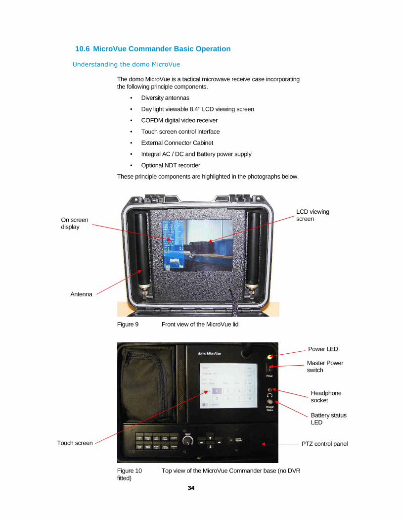
10.6 MicroVue Commander Basic Operation
Understanding the domo MicroVue
The domo MicroVue is a tactical microwave receive case incorporating the following principle components.
• Diversity antennas
• Day light viewable 8.4’’ LCD viewing screen
• COFDM digital video receiver
• Touch screen control interface
• External Connector Cabinet
• Integral AC / DC and Battery power supply
• Optional NDT recorder
These principle components are highlighted in the photographs below.
Figure 9 Front view of the MicroVue lid
Figure 10 Top view of the MicroVue Commander base (no DVR fitted)
Antenna
On screen display
LCD viewing screen
Power LED
Battery status LED
Headphone socket
Master Power switch
Touch screen PTZ control panel
35
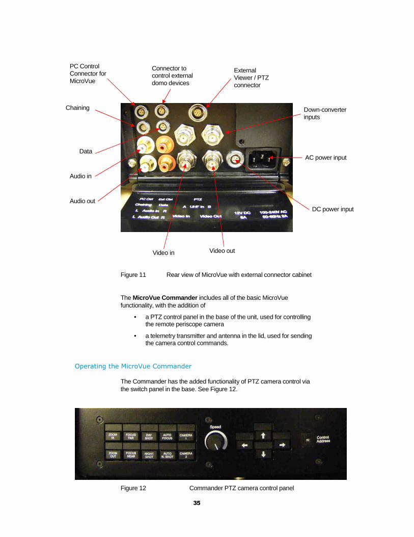
Figure 11 Rear view of MicroVue with external connector cabinet
The MicroVue Commander includes all of the basic MicroVue functionality, with the addition of
• a PTZ control panel in the base of the unit, used for controlling the remote periscope camera
• a telemetry transmitter and antenna in the lid, used for sending the camera control commands.
Operating the MicroVue Commander
The Commander has the added functionality of PTZ camera control via the switch panel in the base. See Figure 12.
Figure 12 Commander PTZ camera control panel
PC Control Connector for MicroVue
Connector to control external domo devices
Audio in
Audio out
External Viewer / PTZ connector
Down-converter inputs
Video in Video out
Chaining
Data
DC power input
AC power input

36
The switch panel functionality is outlined in Table 3.
Table 3 MicroVue Commander switch panel functions
Button Use
Zoom in 36x optical zoom and 12x digital zoom.
Zoom out Zooms out
Focus far Forces the camera to focus on objects in the distance.
Focus near Forces the camera to focus on objects in the foreground.
Day shot Forces the camera into day shot mode
Night shot Forces the camera into night shot mode
Auto focus Pressing and holding this button for three seconds will
make the camera automatically adjust its focus when
panning, tilting or zooming.
Auto night shot Pressing and holding this button for three seconds will
make the camera automatically switch to night shot mode
when light levels fall.
Camera 1 Selects video from camera input 1 on ClearCam.
Camera 2 Selects video from camera input 2 on ClearCam.
Speed Sets the speed at which the unit pans and tilts. Note: If the
speed is turned to zero, no panning or tilting will result.
Pan (left-right) arrows Moves camera through 400° panning range .
Tilt (up-down) arrows Moves camera through +20° to -40° tilt range.
Control address Hex switch to select a specific ClearCam to control (see
paragraph below).
As shown in Figure 12, the Commander base panel contains a CONTROL ADDRESS rotary hex switch.
This potentially gives the user the ability to control up to 15 remote ClearCam units from one MicroVue.
To do so, the Channel number of the Commander can be changed to match that of the target ClearCam unit. Only that ClearCam will then respond to the PTZ commands sent by the Commander. See Figure 13.

37
.
.
.
ClearCam 1
ClearCam 2
ClearCam 15
Control address = 2
MicroVue Commander
PTZ commands sent toall units
Only Camera 2 respondsto commands
Figure 13 Commander and ClearCam control address illustration
By default, all ClearCam units are set to Channel 15. Hence, the Commander has to be set to Channel 15 for the PTZ t o work when the user first receives the equipment.
Before switching on, make sure that the telemetry transmit antenna has been screwed into the top of the Commander lid.
38
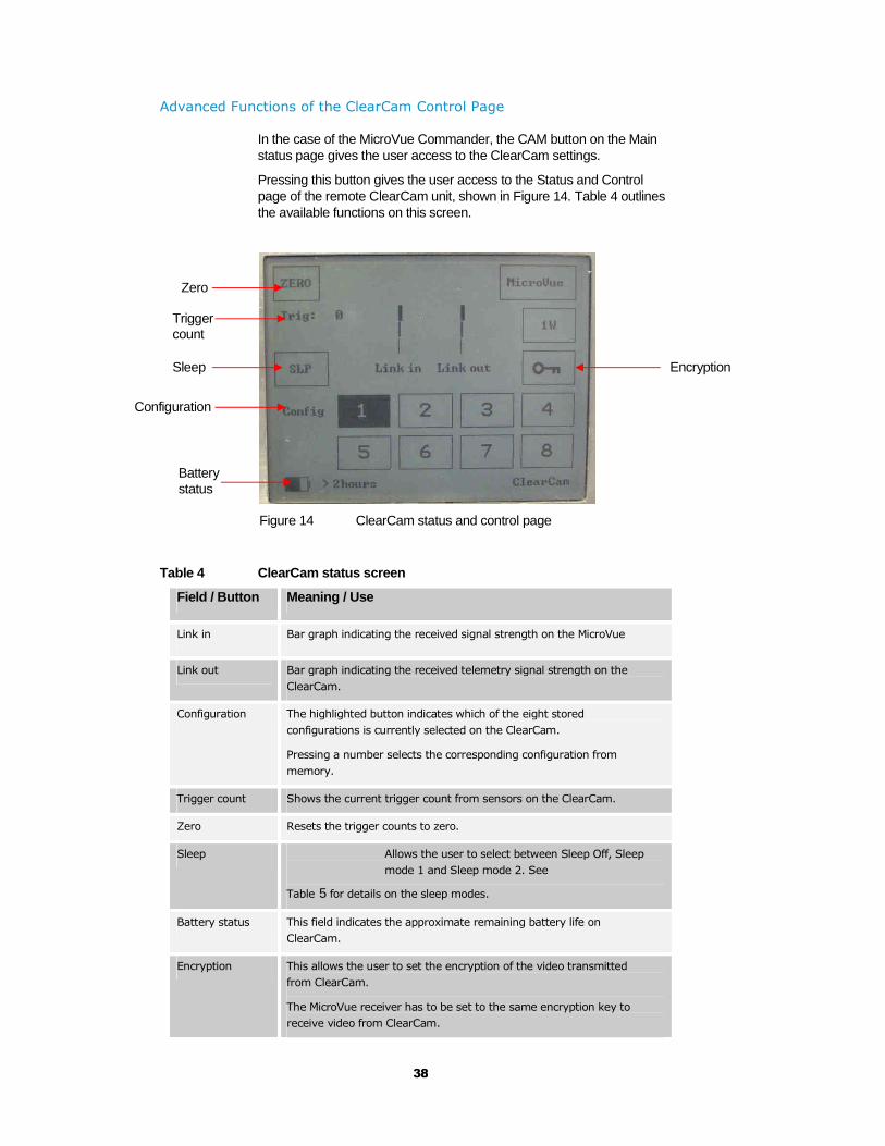
Advanced Functions of the ClearCam Control Page
In the case of the MicroVue Commander, the CAM button on the Main status page gives the user access to the ClearCam settings.
Pressing this button gives the user access to the Status and Control page of the remote ClearCam unit, shown in Figure 14. Table 4 outlines the available functions on this screen.
Figure 14 ClearCam status and control page
Table 4 ClearCam status screen
Field / Button Meaning / Use
Link in Bar graph indicating the received signal strength on the MicroVue
Link out Bar graph indicating the received telemetry signal strength on the
ClearCam.
Configuration The highlighted button indicates which of the eight stored
configurations is currently selected on the ClearCam.
Pressing a number selects the corresponding configuration from
memory.
Trigger count Shows the current trigger count from sensors on the ClearCam.
Zero Resets the trigger counts to zero.
Sleep Allows the user to select between Sleep Off, Sleep
mode 1 and Sleep mode 2. See
Table 5 for details on the sleep modes.
Battery status This field indicates the approximate remaining battery life on
ClearCam.
Encryption This allows the user to set the encryption of the video transmitted
from ClearCam.
The MicroVue receiver has to be set to the same encryption key to
receive video from ClearCam.
Configuration
Trigger count
Sleep
Zero
Battery status
Encryption

39
1W This button toggles between 1W and 100mW transmit power on
ClearCam.
When ClearCam is in 1W mode, the button is highlighted.
MicroVue This allows the user to navigate back to the Main MicroVue status
page.
Table 5 ClearCam sleep modes
Mode Function
Off Both Solo transmitter and Telemetry receiver on ClearCam are active
constantly.
Sleep mode 1 When the ClearCam is put into Sleep mode 1, the Solo transmitter
on ClearCam will turn off after a set number of minutes of trigger
inactivity.
This number is set in the PC control application as Sleep Timeout and
can be in the range of 1-9 minutes.
The unit can be woken up in two ways: Trigger activity on the
ClearCam, or turning sleep OFF in the Sleep menu.
Sleep mode 2 When the ClearCam is put into Sleep mode 2, both the Solo
transmitter and Telemetry receiver on ClearCam will turn off after a
set number of minutes of trigger inactivity.
This number is set in the PC control application as Sleep Timeout and
can be in the range of 1-9 minutes.
Sleep mode 2 saves the most amount of battery life.
Once asleep, the unit can be woken up only through trigger activity
on the ClearCam, or via the ClearCam PC control application.
40
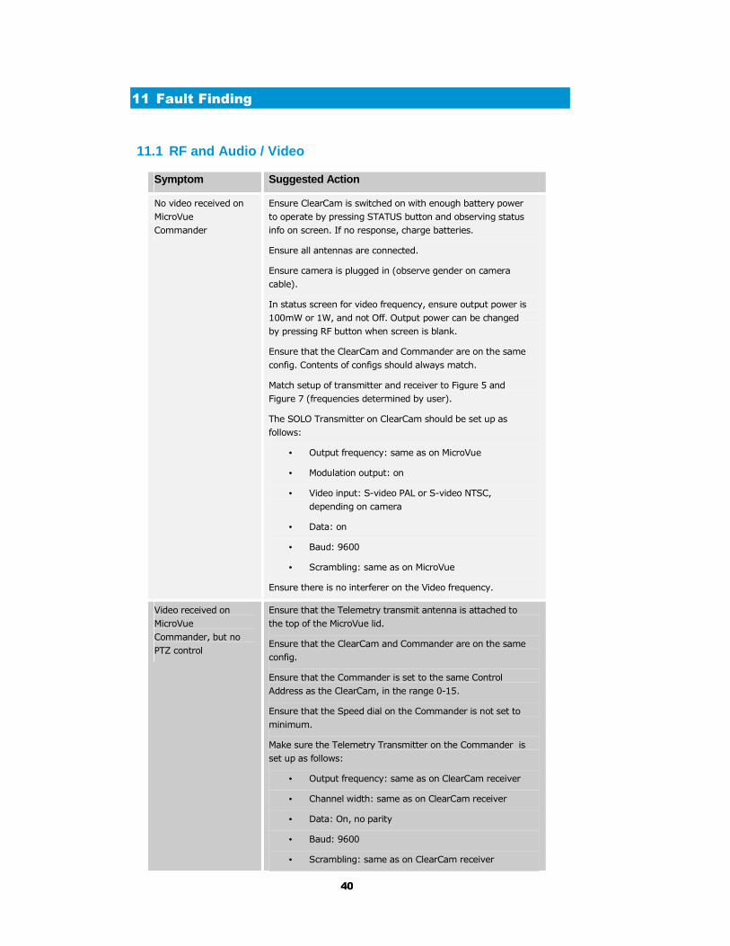
11 Fault Finding
11.1 RF and Audio / Video
Symptom Suggested Action
No video received on
MicroVue
Commander
Ensure ClearCam is switched on with enough battery power
to operate by pressing STATUS button and observing status
info on screen. If no response, charge batteries.
Ensure all antennas are connected.
Ensure camera is plugged in (observe gender on camera
cable).
In status screen for video frequency, ensure output power is
100mW or 1W, and not Off. Output power can be changed
by pressing RF button when screen is blank.
Ensure that the ClearCam and Commander are on the same
config. Contents of configs should always match.
Match setup of transmitter and receiver to Figure 5 and
Figure 7 (frequencies determined by user).
The SOLO Transmitter on ClearCam should be set up as
follows:
• Output frequency: same as on MicroVue
• Modulation output: on
• Video input: S-video PAL or S-video NTSC,
depending on camera
• Data: on
• Baud: 9600
• Scrambling: same as on MicroVue
Ensure there is no interferer on the Video frequency.
Video received on
MicroVue
Commander, but no
PTZ control
Ensure that the Telemetry transmit antenna is attached to
the top of the MicroVue lid.
Ensure that the ClearCam and Commander are on the same
config.
Ensure that the Commander is set to the same Control
Address as the ClearCam, in the range 0-15.
Ensure that the Speed dial on the Commander is not set to
minimum.
Make sure the Telemetry Transmitter on the Commander is
set up as follows:
• Output frequency: same as on ClearCam receiver
• Channel width: same as on ClearCam receiver
• Data: On, no parity
• Baud: 9600
• Scrambling: same as on ClearCam receiver
41
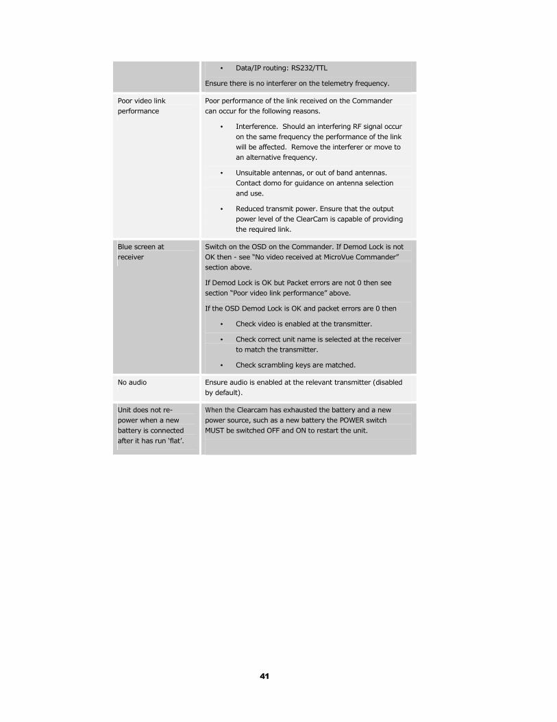
• Data/IP routing: RS232/TTL
Ensure there is no interferer on the telemetry frequency.
Poor video link
performance
Poor performance of the link received on the Commander
can occur for the following reasons.
• Interference. Should an interfering RF signal occur
on the same frequency the performance of the link
will be affected. Remove the interferer or move to
an alternative frequency.
• Unsuitable antennas, or out of band antennas.
Contact domo for guidance on antenna selection
and use.
• Reduced transmit power. Ensure that the output
power level of the ClearCam is capable of providing
the required link.
Blue screen at
receiver
Switch on the OSD on the Commander. If Demod Lock is not
OK then - see “No video received at MicroVue Commander”
section above.
If Demod Lock is OK but Packet errors are not 0 then see
section “Poor video link performance” above.
If the OSD Demod Lock is OK and packet errors are 0 then
• Check video is enabled at the transmitter.
• Check correct unit name is selected at the receiver
to match the transmitter.
• Check scrambling keys are matched.
No audio Ensure audio is enabled at the relevant transmitter (disabled
by default).
Unit does not re-
power when a new
battery is connected
after it has run ‘flat’.
When the Clearcam has exhausted the battery and a new
power source, such as a new battery the POWER switch
MUST be switched OFF and ON to restart the unit.

42
12 Connector Pin Outs
12.1 Power: 2-pin Amphenol (62GB-12E10-02SN)
Pin No Function
A 12 V
B 12 V
C GND
D GND
Mating connector and backshell: APH 62GB-56T-CGMSA-10-02PN
12.2 RS232 PC Control: 3-pin Amphenol (62GB-12E08-0 3SN)
Pin No Function
A TX
B RX
C GND
Mating connector and backshell: APH 62GB-56T-CGMSA-08-03PN
12.3 Sensor: 8-pin Amphenol (62GB-12E12-08SN)
Pin No Function
A Sensor 1, 12V
B Sensor 1, GND
C Sensor 1, V1
D Sensor 1, V2
E Sensor 2, 12V
F Sensor 2, GND
H Sensor 2, V1
J Sensor 2, V2
Mating connector and backshell: APH 62GB-56T-CGMSA-12-08PN

43
12.4 Audio in/out: 6-pin Amphenol (62GB-12E10-06SN)
Pin No Function
A Audio out, L
B Audio out, GND
C Audio out, R
D Audio in, L
E Audio in, GND
F Audio in, R
Mating connector and backshell: APH 62GB-56T-CGMSA-10-06PN
12.5 Camera: 14-pin Amphenol (62GB-12E12-14SN)
Pin No Function
A +12V
B GND
C Pan 1
D Pan 2
E Tilt 1
F Tilt 2
H Luma
J Luma GND
K Chroma
L Chroma GND
M No connection
N No connection
P Serial control
R No connection
Mating connector and backshell: APH 62GB-56T-CGMSA-12-14PN
44
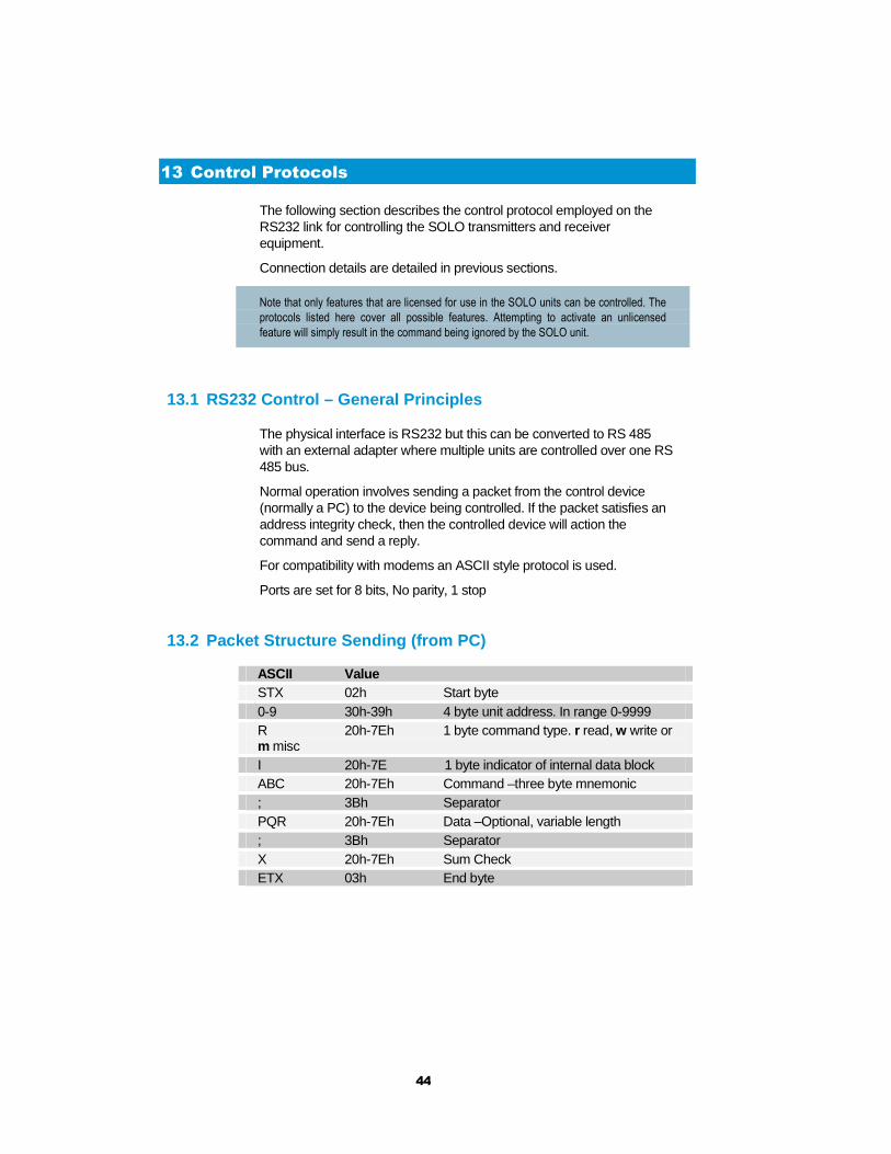
13 Control Protocols
The following section describes the control protocol employed on the RS232 link for controlling the SOLO transmitters and receiver equipment.
Connection details are detailed in previous sections.
Note that only features that are licensed for use in the SOLO units can be controlled. The
protocols listed here cover all possible features. Attempting to activate an unlicensed
feature will simply result in the command being ignored by the SOLO unit.
13.1 RS232 Control – General Principles
The physical interface is RS232 but this can be converted to RS 485 with an external adapter where multiple units are controlled over one RS 485 bus.
Normal operation involves sending a packet from the control device (normally a PC) to the device being controlled. If the packet satisfies an address integrity check, then the controlled device will action the command and send a reply.
For compatibility with modems an ASCII style protocol is used.
Ports are set for 8 bits, No parity, 1 stop
13.2 Packet Structure Sending (from PC)
ASCII Value STX 02h Start byte 0-9 30h-39h 4 byte unit address. In range 0-9999 R 20h-7Eh 1 byte command type. r read, w write or m misc I 20h-7E 1 byte indicator of internal data block ABC 20h-7Eh Command –three byte mnemonic ; 3Bh Separator PQR 20h-7Eh Data –Optional, variable length ; 3Bh Separator X 20h-7Eh Sum Check ETX 03h End byte
45
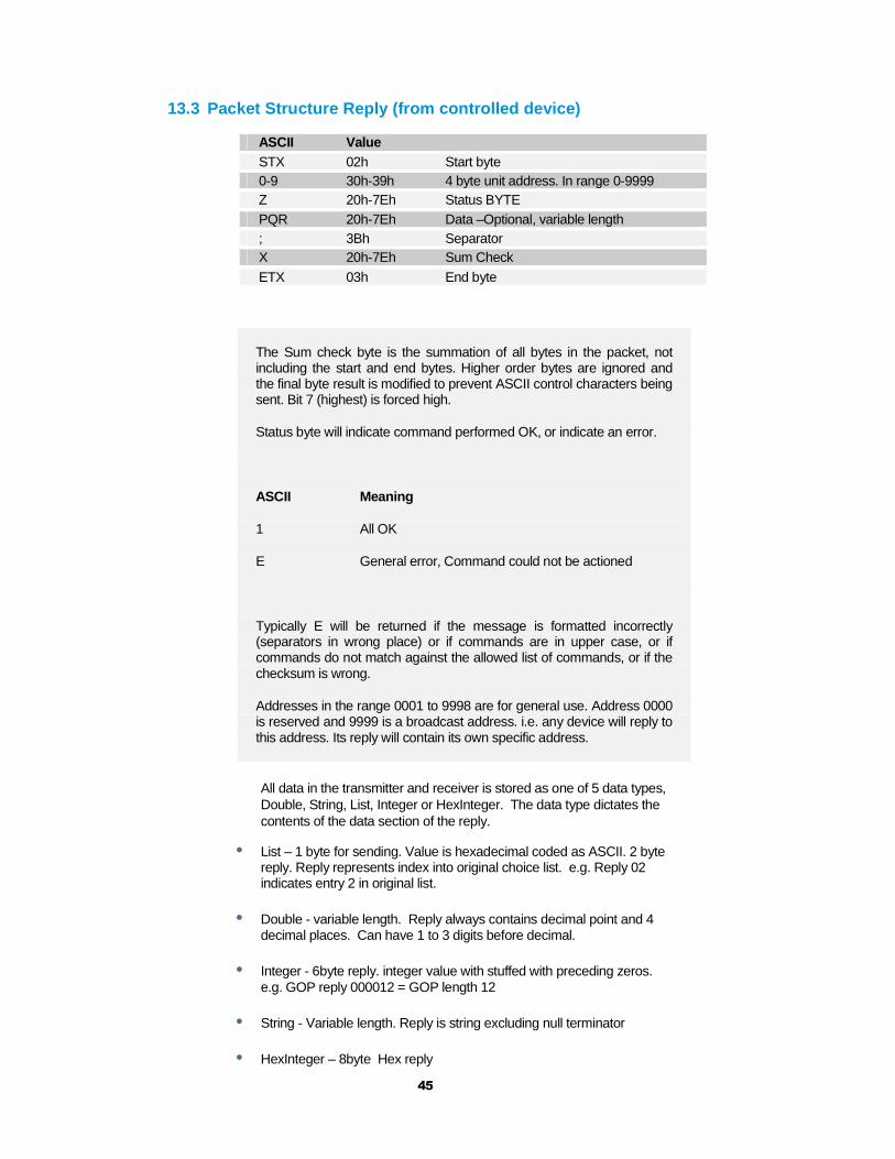
13.3 Packet Structure Reply (from controlled device )
ASCII Value STX 02h Start byte 0-9 30h-39h 4 byte unit address. In range 0-9999 Z 20h-7Eh Status BYTE PQR 20h-7Eh Data –Optional, variable length ; 3Bh Separator X 20h-7Eh Sum Check
ETX 03h End byte
The Sum check byte is the summation of all bytes in the packet, not including the start and end bytes. Higher order bytes are ignored and the final byte result is modified to prevent ASCII control characters being sent. Bit 7 (highest) is forced high.
Status byte will indicate command performed OK, or indicate an error.
ASCII Meaning
1 All OK
E General error, Command could not be actioned
Typically E will be returned if the message is formatted incorrectly (separators in wrong place) or if commands are in upper case, or if commands do not match against the allowed list of commands, or if the checksum is wrong.
Addresses in the range 0001 to 9998 are for general use. Address 0000 is reserved and 9999 is a broadcast address. i.e. any device will reply to this address. Its reply will contain its own specific address.
All data in the transmitter and receiver is stored as one of 5 data types, Double, String, List, Integer or HexInteger. The data type dictates the contents of the data section of the reply.
• List – 1 byte for sending. Value is hexadecimal coded as ASCII. 2 byte reply. Reply represents index into original choice list. e.g. Reply 02 indicates entry 2 in original list.
• Double - variable length. Reply always contains decimal point and 4 decimal places. Can have 1 to 3 digits before decimal.
• Integer - 6byte reply. integer value with stuffed with preceding zeros. e.g. GOP reply 000012 = GOP length 12
• String - Variable length. Reply is string excluding null terminator
• HexInteger – 8byte Hex reply

46
13.4 Receiver Command List
Type ‘1’ messages for Tuner / Demod
Description Type Block Command Data Sent
Data Type
Input Frequency
r/w 1 ipf This is the frequency received by the antenna. Decimal point allowed.
Double
Down Converter LO
r/w 1 dco Decimal point allowed.
Double
Down Converter LO Side
r/w 1 los 0=low 1=high
List
OFDM Bandwidth
r/w 1 wid N.Band Mode 3 = 2.5MHz DVBT Mode 0 = 8MHz 1 = 7MHz 2 = 6MHz
List
OFDM Modulation Mode
r 1 mod N.Band Mode 0 = QPSK 1 = 16QAM DVBT Mode 0 = QPSK 1 = 16QAM 2 = 64QAM
List
OFDM FEC r 1 fec N.Band Mode 1 = 2/3 2 = 1/3 DVBT Mode 0 = 1/2 1 = 2/3 2 = 3/4 3 = 5/6 4 = 7/8
List
OFDM Guard
N.Band Mode r/w DVBT Mode r
1 gua N.Band Mode 1 = 1/16 2 = 1/8 DVBT Mode 0 = 1/32 1 = 1/16 2 = 1/8 3 = 1/4
List
OFDM Pol
r 1 pol 0 = Normal 1 = Inverted
List
Input SNR A r 1 snr Input SNR in dB Double Input SNR B r 1 mer Input SNR in dB Double Input SNR C r 1 cer Input SNR in dB Double Input SNR D r 1 dnr Input SNR in dB Double BER Pre Viterbi
r 1 pre Pre Viterbi x 10-6 Int
BER Post Viterbi
r 1 pos Post Viterbi x 10-6 Int
Packet errors r 1 pkt Int Lock Status r 1 loc 0 = Not Locked
1 = Locked List
Input Level A r 1 ina Input Level in dBm Double Input Level B r 1 inb Input Level in dBm Double Input Level C r 1 Inc Input Level in dBm Double Input Level D r 1 ind Input Level in dBm Double
47
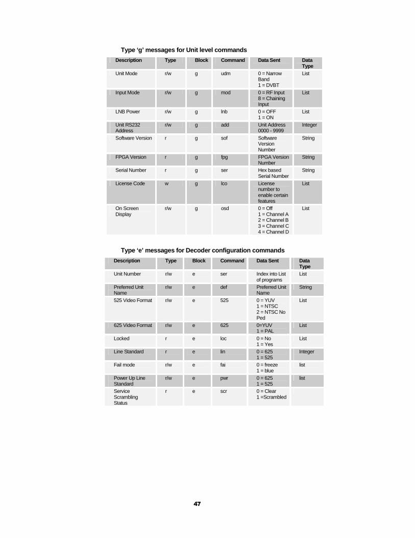
Type ‘g’ messages for Unit level commands
Description Type Block Command Data Sent
Data Type
Unit Mode r/w g udm 0 = Narrow Band 1 = DVBT
List
Input Mode r/w g mod 0 = RF Input 8 = Chaining Input
List
LNB Power r/w g lnb 0 = OFF 1 = ON
List
Unit RS232 Address
r/w g add Unit Address 0000 - 9999
Integer
Software Version r g sof Software Version Number
String
FPGA Version r g fpg FPGA Version Number
String
Serial Number r g ser Hex based Serial Number
String
License Code w g lco License number to enable certain features
List
On Screen Display
r/w g osd 0 = Off 1 = Channel A 2 = Channel B 3 = Channel C 4 = Channel D
List
Type ‘e’ messages for Decoder configuration command s
Descrip tion Type Block Command Data Sent
Data Type
Unit Number r/w e ser Index into List of programs
List
Preferred Unit Name
r/w e def Preferred Unit Name
String
525 Video Format r/w e 525 0 = YUV 1 = NTSC 2 = NTSC No Ped
List
625 Video Format r/w e 625 0=YUV 1 = PAL
List
Locked r e loc 0 = No 1 = Yes
List
Line Standard r e lin 0 = 625 1 = 525
Integer
Fail mode r/w e fai 0 = freeze 1 = blue
list
Power Up Line Standard
r/w e pwr 0 = 625 1 = 525
list
Service Scrambling Status
r e scr 0 = Clear 1 =Scrambled

48
Type ‘d’ messages for Memory configuration commands
Description Type Block Command Data Sent
Data Type
Store Current Configuration to Memory
r/w d sto Config Address (1 to 9)
Integer
Load Configuration from Memory into current
r/w d loa Config Address (1 to 9)
Integer
Restore Default Build
r/w d def 0 = No 1 = Yes
List
Read number of last config loaded
r d las Config Address
Integer
Type ‘z’ messages for Descrambling commands
Description Type Block Command Data Sent
Data Type
Descrambling r/w z des 0 = Off 1 = ABS 4 = AES128 5 = AES128+ 6 = AES256 7= AES256+
List
ABS Scrambling Key
w z ebs Alink basic scrambling key
8-digit hex string
AES Scrambling Key – lower 128 bits
w z aes Advanced Encryption Standard – lower 128 bits
32-digit hex string
AES Scrambling Key – upper 128 bits used in AES256 only
w z a25 Advanced Encryption Standard – upper 128 bits
32-digit hex string
Type ‘t’ messages for RS232 data pipe commands
Description Type Block Command Data Sent Data Type
Data On/Off r/w t dat 0 = Off 1 = On
List
Data Baudrate
r t bau 2 = 1200 baud 3 = 2400 baud 4 = 4800 baud 5 = 9600 baud 6 = 19200 baud 7 = 38400 baud
8 = 57600 baud 9 = 115200 baud
List
Data Parity r/w t par 0 = none 1 = even 2 = odd
List

49
14 Default Configurations
This section tabulates the default configuration settings for domo ClearCam and MicroVue Commander.
14.1 SOL4CLCP-240045 (PAL, S-Band Video, 458MHz Tel emetry)
All configuration parameters are identical over the 8 configurations in the ClearCam and the MicroVue Commander except the video channel operating frequency which varies per configuration.
Video Frequency settings (Clearcam TX and MicroVue RX Frequency)
Table 6 SOL4CLCP-240045 Video Frequency Settings
Configuration 1 2 3 4 5 6 7 8
Frequency (MHz)
2405 2415 2425 2435 2405 2415 2425 2435
Telemetry Frequency settings (Clearcam RX and MicroVue TX frequency)
Table 7 SOL4CLCP-240045 Telemetry Frequency Settin gs
Configuration 1 2 3 4 5 6 7 8
Frequency (MHz)
458.55 458.55 458.55 458.55 458.55 458.55 458.55 458.55
Note: By default, the ClearCam camera 1 video input and camera 2 video input expect S-video and not composite video. This can be altered to be composite video using the ClearCam controller, if required.

50
14.2 SOL4CLCP-240086 (PAL, S-Band Video, 868MHz Tel emetry)
Video Frequency settings (Clearcam TX and MicroVue RX Frequency)
Table 8 SOL4CLCP-240086 Video Frequency Settings
Configuration 1 2 3 4 5 6 7 8
Frequency (MHz)
2405 2415 2425 2435 2405 2415 2425 2435
Telemetry Frequency settings (Clearcam RX and MicroVue TX frequency)
Table 9 SOL4CLCP-240086 Telemetry Frequency Settin gs
Configuration 1 2 3 4 5 6 7 8
Frequency (MHz)
869.45 869.45 869.45 869.45 869.45 869.45 869.45 869.45
Note: By default, the ClearCam camera 1 video input and camera 2 video input expect S-video and not composite video. This can be altered to be composite video using the ClearCam PC control application, if required.
14.3 SOL4CLCN-240090 (NTSC, S-Band Video, 903MHz Te lemetry)
Video Frequency settings (Clearcam TX and MicroVue RX Frequency)
Table 10 SOL4CLCN-240090 Video Frequency Settings
Configuration 1 2 3 4 5 6 7 8
Frequency (MHz)
2405 2415 2425 2435 2405 2415 2425 2435
Telemetry Frequency settings (Clearcam RX and MicroVue TX frequency)
Table 11 SOL4CLCN-240090 Telemetry Frequency Settin gs
Configuration 1 2 3 4 5 6 7 8
Frequency (MHz)
TBD.xx TBD.xx TBD.xx TBD.xx TBD.xx TBD.xx TBD.xx TBD.xx
Note: By default, the ClearCam camera 1 video input and camera 2 video input expect S-video and not composite video. This can be

51
altered to be composite video using the ClearCam PC control application, if required.
14.4 Common Default Settings
The majority of settings on both the ClearCam and the MicroVue Commander never need to be altered by a standard user. The defaults for these settings are listed below, as they will appear upon arrival and after loading the Config Set supplied with the unit.
ClearCam
Table 12 Video Transmitter Basic Settings
Item Video Transmitter
Frequency Specific to Model (see above)
Bandwidth Mode Narrowband
Default Transmit
Mode
Medium Range
Scrambling OFF
Output Status 100mW
Table 13 Video Transmitter Advanced Settings
Item Video Transmitter
Modulation
Bandwidth
2.5MHz
Modulation
Output
On
Narrowband FEC 2/3
Narrowband
Guard Interval
1/16
Output Power High
Output
Attenuation High
0dB
Output Status 1W out
Video Input S-Video PAL
MPEG Mode MPEG-2
MPEG-4 encoding
mode
Low delay interlaced
MPEG4 frame
rate
Full
Video sharpness Normal
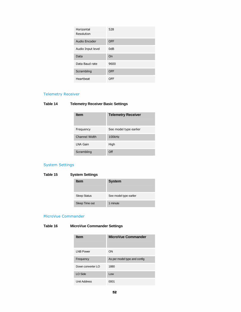
52
Horizontal
Resolution
528
Audio Encoder OFF
Audio Input level 0dB
Data On
Data Baud rate 9600
Scrambling OFF
Heartbeat OFF
Telemetry Receiver
Table 14 Telemetry Receiver Basic Settings
Item Telemetry Receiver
Frequency See model type earlier
Channel Width 100kHz
LNA Gain High
Scrambling Off
System Settings
Table 15 System Settings
Item System
Sleep Status See model type earlier
Sleep Time out 1 minute
MicroVue Commander
Table 16 MicroVue Commander Settings
Item MicroVue Commander
LNB Power ON
Frequency As per model type and config
Down converter LO 1880
LO Side Low
Unit Address 0001
53
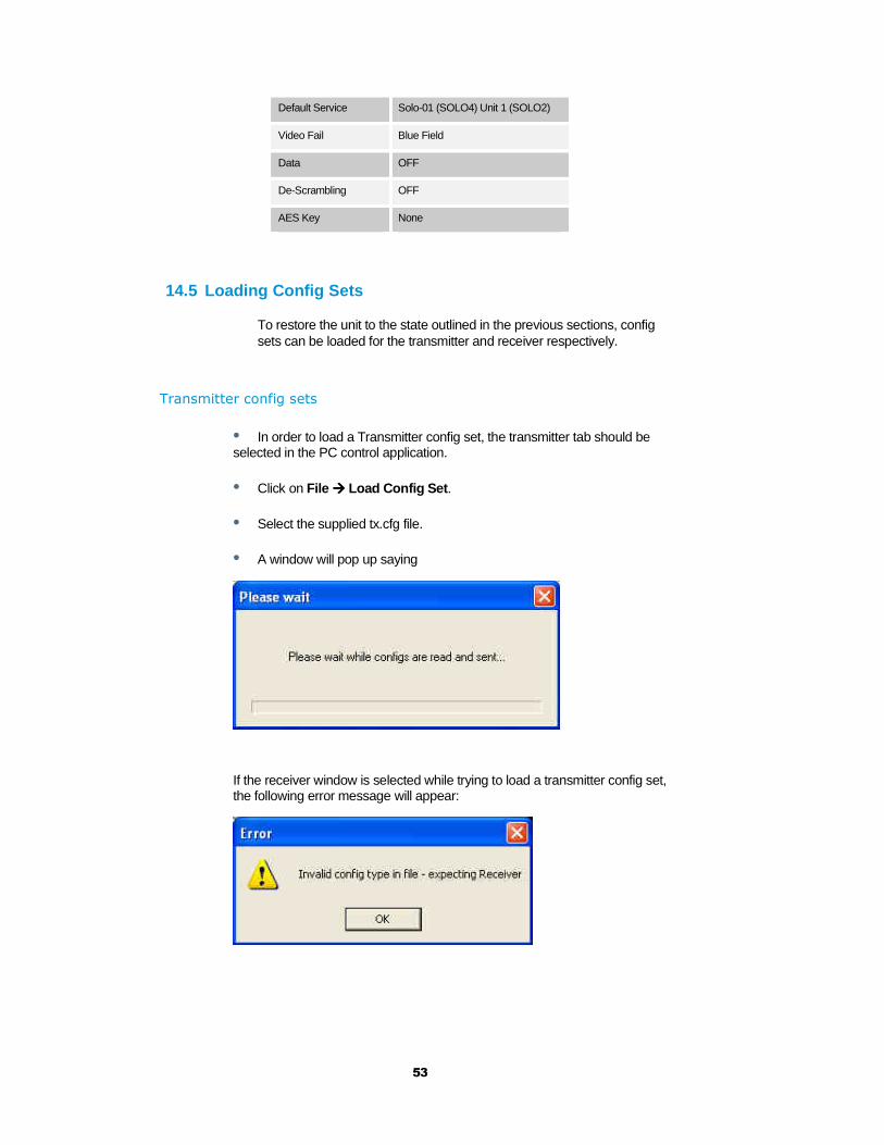
Default Service Solo-01 (SOLO4) Unit 1 (SOLO2)
Video Fail Blue Field
Data OFF
De-Scrambling OFF
AES Key None
14.5 Loading Config Sets
To restore the unit to the state outlined in the previous sections, config sets can be loaded for the transmitter and receiver respectively.
Transmitter config sets
• In order to load a Transmitter config set, the transmitter tab should be selected in the PC control application.
• Click on File ���� Load Config Set .
• Select the supplied tx.cfg file.
• A window will pop up saying
If the receiver window is selected while trying to load a transmitter config set, the following error message will appear:

54
Receiver config sets
• In order to load a Receiver config set, the receiver tab should be selected in the PC control application.
• Click on File ���� Load Config Set .
• Select the supplied rx.cfg file.
• A window will pop up saying
If the transmitter window is selected while trying to load a receiver config set, the following error message will appear:

55
15 Technical specifications
15.1 ClearCam Specification
Antennas Transmit Antenna
Receive Antenna
4dBi Colinear TNC mount flexible
2dBi Colinear BNC mount flexible
Input / Output
DC Power
GPIO trigger input
RS-232 control
Audio Input and
output
Camera 1
connector Camera 2 connector
Amphenol connectors
62GB-12E10-02SN
62GB-12E12-08SN
62GB-12E08-03SN
62GB-12E10-06SN
62GB-12E12-14SN
62GB-12E12-14SN
RF
Transmit Frequency
Bands
Transmit Power
Tuning Steps
Receive Frequency
Bands
Receive Sensitivity
SOL4CLCx-240045 and SOL4CLCx-
240086
2.28 to 2.55GHz tunable
SOL4CLCx-120045
1.15 to 1.4GHz tunable
30dBm (1W)
250kHz
SOL4CLCx-240045 and SOL4CLCx-
120045
458.5 to 459.5MHz tunable
SOL4CLCx-240086
868 to 870MHz tunable
-118dBm typical
Modulation Transmit modes
Bandwidth
Modulation
FEC
Bitrate
2.5MHz or 1.25MHz
QPSK or 16QAM
1/3 or 2/3
600kb/s to 4.8Mb/s
PTZ Camera Camera
Range of PTZ
Zoom
Low Light
Minimum
illumination
Line standard
Sony FCBEX1000
400 degree pan, +20 to -40 vertical
36x Optical and 12x digital
Yes
0.1 lux with 1/4s shutter speed;
equivalent to full moon at night
1.4 lux with 1/60s shutter speed;
equivalent to deep twilight
P model PAL, N model NTSC

56
Video Encoding Resolution
Coding mode
Delay
Frame rate
704, 528, 480, 352
MPEG2 or MPEG4 (optional)
43ms to 1sec depending on mode
Full / Half / Quarter / Eighth
(optional)
Audio Level
Sample rate
Bits per sample
Line Level
32kHz, 16kHz, 8kHz
12- or 8-bit
Sensors Inputs Quantity
Format
1
Closed Contact Detection
Sleep Options Modes
Wake Period
Wake on trigger input / Wake on
user instruction
1-9 min, user definable
Encryption Format
ABS (standard)
AES128 / 256 selectable (optional)
Control Remote control
Local control
Over air from MicroVue Commander
case
PC Control Using PC RS232 Application
On/Off switch, transmit switch,
channel switch and status switch
User status display indicates
battery life and link status
Physical Base dimensions
(LxWxH)
Camera dimensions
(Hxd)
Camera base
diameter
Weight
280 x 200 x 90 mm
340 x 75 mm
110 mm
8kg (base 7kg; camera 1kg)
Power DC input (8A fused)
Battery backup
(internal fuse)
Battery technology
11-16V (Reverse Polarity
Protected)
3.5 hours continuous operation in
1W mode
7 hours continuous operation in
100mW mode
NiMH
Environment Temperature Range Protection
-10 to +50 deg C Dry Nitrogen purged periscope
cam.
57
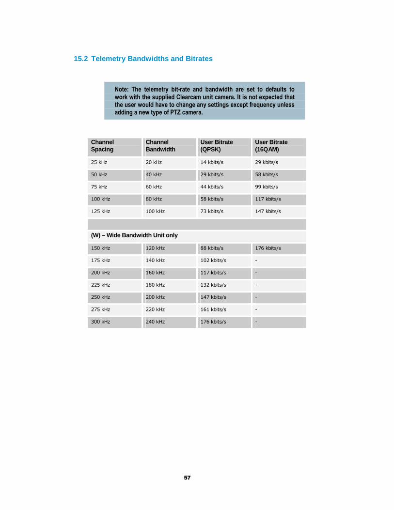
15.2 Telemetry Bandwidths and Bitrates
Note: The telemetry bit-rate and bandwidth are set to defaults to work with the supplied Clearcam unit camera. It is not expected that the user would have to change any settings except frequency unless adding a new type of PTZ camera.
Channel Spacing
Channel Bandwidth
User Bitrate (QPSK)
User Bitrate (16QAM)
25 kHz 20 kHz 14 kbits/s 29 kbits/s
50 kHz 40 kHz 29 kbits/s 58 kbits/s
75 kHz 60 kHz 44 kbits/s 99 kbits/s
100 kHz 80 kHz 58 kbits/s 117 kbits/s
125 kHz 100 kHz 73 kbits/s 147 kbits/s
(W) – Wide Bandwidth Unit only
150 kHz 120 kHz 88 kbits/s 176 kbits/s
175 kHz 140 kHz 102 kbits/s -
200 kHz 160 kHz 117 kbits/s -
225 kHz 180 kHz 132 kbits/s -
250 kHz 200 kHz 147 kbits/s -
275 kHz 220 kHz 161 kbits/s -
300 kHz 240 kHz 176 kbits/s -

58
Cobham Surveillance
Domo Products
11 Manor Court, Barnes Wallis Road, Segensworth, Hampshire, PO15 5TH, England
T: +44 (0)1489 566 750
F: +44 (0)1489 880 538


