Download - COAL HANDLING DIVISION/PLANT, ANPARA
PrefaceThis Project Report entitled “COAL HANDLING PLANT” has been prepared in fulfilment of Industrial Training to be carried out in second year of our four year B.TECH course. For preparing the Project Report, I have visited Anpara Thermal Power Station underUttarPradeshRajyaVidyutUtpadan NigamLtd.during the suggested duration for the period of 28 days, to avail necessary information. The blend of learning and knowledge acquired during our practical studies at the company is presented in this Project Report.
The rationale behind visiting the power plant and preparing this Project Report is to study electrical overview related to power generation and its auxiliaries in thermal power plant.
We have carried out this training under well experienced and highly qualified engineers of ATPS, UPRVUNL of various departments. We have taken the opportunity to explore the coal handling division(C.H.D.),its use, necessity in power plant and maintenance of various equipment used for power generation and controlling the numerous process of power generation. I have tried our best to cover all the aspects of power plant specially stacking and their brief detailing in this project report.
All the above mention topic will be presented in the following pages of this report. The main aim to carry out this project is to familiarize ourselves with the real industrial scenario, so that we can relate with our engineering studies.

AcknowledgementI take this opportunity to express my profound gratitude and deep regards toEr. SURYA PRAKASH PAL Asst.Engineer for his exemplary guidance, monitoring and constant encouragement throughout the course of this project. The blessing, help and guidance given by him time to time shall carry me a long way in the journey of life on which I am about to embark.
I also take this opportunity to express a deep sense of gratitude to Er.A. S. MISHRA Executive Engineer CHD-I Anpara Thermal Power Station, UPRVUNL for their cordial support, valuable information and guidance, which helped me in completing this task through various stages.
I am also thankful to Er. NIKHIL CHATURVEDI Executive Engineer HRD &Trg. Division for providing me opportunity to carry out my vocational training in ATPS.
I am obliged to staff members of Anpara Thermal Power Station, UPRVUNL for the valuable information provided by them in their respective fields. I am grateful for their cooperation during the period of my assignment.
Lastly, I thank almighty, my parents, sister and friends for their constant encouragement without which this assignment would not be possible
RAJAT VERMA
B.tech (Elect.Engg) IIIrdYear
ANPARA THERMAL POWER STATIONThe Anpara Power Plant is located near village Anpara on the bank of Rihand reservoir in the district of Sonebhadra (Uttar Pradesh). It is about 34 km from Rihand Dam on Pipri-Singrauli road and about 200 km from Varanasi. Varanasi is connected by air/rail and road route from other major cities.
All the units of Anpara TPS are coal-fired thermal power plants, having a total generating capacity of 1630 MW and consists of following units –
StageUnits No.
Installed Capacity
Derated Capacity
Original Equipment
Manufacturers
'A' TPS
1 210 MW 210 MWM/s Bharat Heavy
Electricals Ltd.
2 210 MW 210 MWM/s Bharat Heavy
Electricals Ltd.
3 210 MW 210 MWM/s Bharat Heavy
Electricals Ltd.
'B' TPS
4 500 MW 500 MWM/s Mitsubishi
Corporation, Japan
5 500 MW 500 MWM/s Mitsubishi
Corporation, Japan

Basic Needs and Overview of a Thermal Power Plant
Steam is an important medium of producing mechanical energy. Steam has the advantage that, it can be raised from water which is available in abundance it does not react much with the materials of the equipment of power plant and is stable at the temperature required in the plant. Steam is used to drive steam engines, steam turbines etc. Steam power station is most suitable where coal is available in abundance. Thermal electrical power generation is one of the major methods. Out of total power developed in India about 60% is thermal. For a thermal power plant the range of pressure may vary from 10 kg/cm2 to super critical pressures and the range of temperature may be from 250°C to 650°C.
Essentials of steam power plant equipment:-
A steam power plant must have following equipment:(a) A furnace to burn the fuel. (b) Steam generator or boiler containing water. Heat generated in the furnace is utilized to convert water into steam. (c) Main power unit such as an engine or turbine to use the heat energy of steam and perform work. (d) Piping system to convey steam and water.
A steam power plant using steam as working substance works basically on Rankine cycle. Steam is generated in a boiler, expanded in the prime mover and condensed in the condenser and fed into the boiler again. The different types of systems and components used in steam power plant are as follows:(a) High pressure boiler
(b) Prime mover
(c) Condensers and cooling towers
(d) Coal handling system
(e) Ash and dust handling system
(f) Draught system
(g) Feed water purification plant
(h) Pumping system

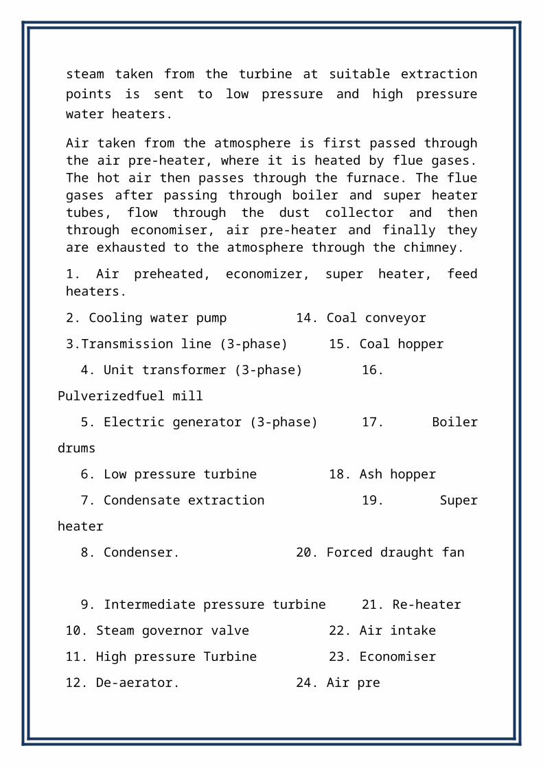
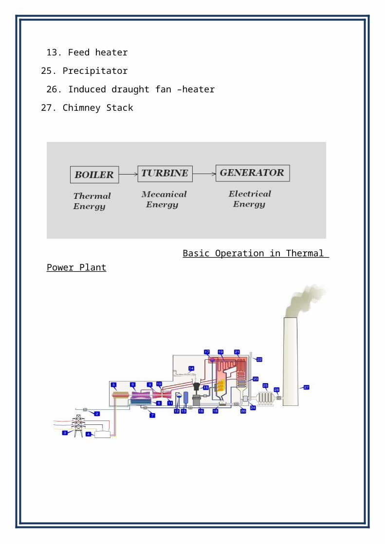
Figure shows a schematic arrangement of equipment of a steam power station. Coal received in coal storage yard of power station is transferred in the furnace by coal handling unit. Heat produced due to burning of coal is utilized in converting water contained in boiler drum into steam at suitable pressure and temperature. The steam generated is passed through the super heater. Superheated steam then flows through the turbine. After doing work in the turbine the pressure of steam is reduced. Steam leaving the turbine passes through the condenser which is maintained the low pressure of steam at the exhaust of turbine. Steam pressure in the condenser depends upon flow rate and temperature of cooling water and on effectiveness of air removal equipment. Water circulating through the condenser may be taken from the various sources such as river, lake or sea. Bled steam taken from the turbine at suitable extraction points is sent to low pressure and high pressure water heaters.
Air taken from the atmosphere is first passed through the air pre-heater, where it is heated by flue gases. The hot air then passes through the furnace. The flue gases after passing through boiler and super heater tubes, flow through the dust collector and then through economiser, air pre-heater and finally they are exhausted to the atmosphere through the chimney.
1. Air preheated, economizer, super heater, feed heaters.
2. Cooling water pump 14. Coal conveyor
3.Transmission line (3-phase) 15. Coal hopper
4. Unit transformer (3-phase) 16. Pulverizedfuel mill
5. Electric generator (3-phase) 17. Boiler drums
6. Low pressure turbine 18. Ash hopper
7. Condensate extraction 19. Super heater
8. Condenser. 20. Forced draught fan
9. Intermediate pressure turbine 21. Re-heater
10. Steam governor valve 22. Air intake
11. High pressure Turbine 23. Economiser
12. De-aerator. 24. Air pre
13. Feed heater 25. Precipitator
26. Induced draught fan –heater
27. Chimney Stack
Basic Operation in Thermal Power Plant

ATPS OVERVIEW3X210 MW
ABSTRACT
Many thermal power plants use coal as their fuel. To handle the coal, each
power station is equipped with a coal handling plant. The coal has to be sized,
processed, and handled which should be done effectively and efficiently. While
working in the coal handling plant the major factor which reduces staff
efficiency is the working environment i.e., dust etc. Generally all systems used
in power station coal handling plants are wet dust suppression systems.
INTRODUCTION
Coal Handling Plant (CHP) is a plant which handles the coal from its receipt to
transporting it to Boiler and store in Bunkers. It also processes the raw coal to
make it suitable for Boiler Operation.
Coal Handling Plant (CHP):-
Extent of work: - In brief we can say that receipt of coal from coal mines,
weighing of coal, crushing it to required size and transferring the quanta of coal
to various coal mill bunkers. This is the responsibility and duty of the CHP and
its staff.
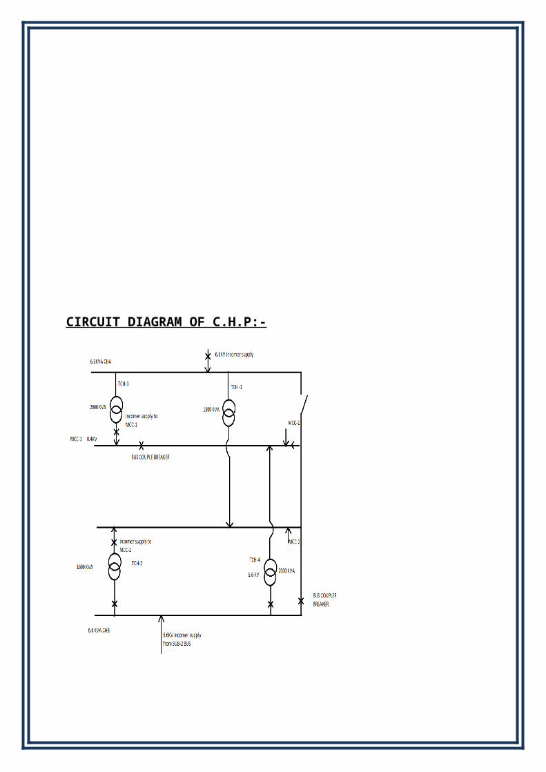
CIRCUIT DIAGRAM OF C.H.P:-
Electrical equipment in C.H.P:-
1. 52 Nos. 6.6 KV JYOTI make breakers.
2. 02 Nos. INCOMERS and 02 no. VT panel.
3. 01 ISOLATER and BUS COUPLER.
4. 27 Nos. 6.6KV MOTORS.
General Working of Coal Handling Plant :-
As mentioned above, coal is brought to power station by either of three means
of coal transportation. This coal is first conveyed to primary crusher with the
help of different combination of conveyor belts and its rate of feeding is
controlled by Electro-magnetic vibrating feeders. Conveyor belt before the
crusher is provided with hanging magnets to separate ferrous materials. Stones
are picked up manually. In primary crusher, coal is first crushed to 150 mm
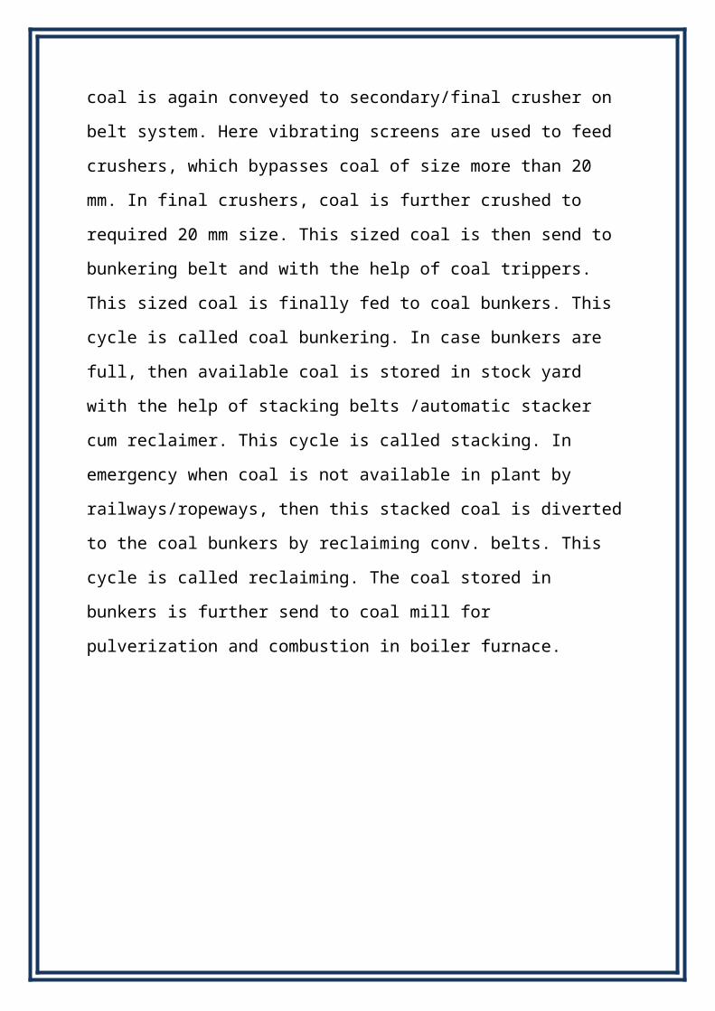
size. This coal is again conveyed to secondary/final crusher on belt system.
Here vibrating screens are used to feed crushers, which bypasses coal of size
more than 20 mm. In final crushers, coal is further crushed to required 20 mm
size. This sized coal is then send to bunkering belt and with the help of coal
trippers. This sized coal is finally fed to coal bunkers. This cycle is called coal
bunkering. In case bunkers are full, then available coal is stored in stock yard
with the help of stacking belts /automatic stacker cum reclaimer. This cycle is
called stacking. In emergency when coal is not available in plant by
railways/ropeways, then this stacked coal is diverted to the coal bunkers by
reclaiming conv. belts. This cycle is called reclaiming. The coal stored in
bunkers is further send to coal mill for pulverization and combustion in boiler
furnace.
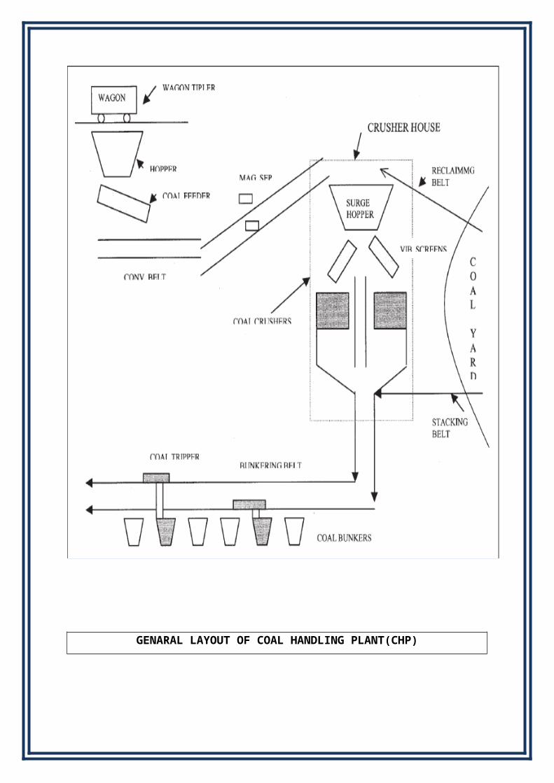
GENARAL LAYOUT OF COAL HANDLING PLANT(CHP)

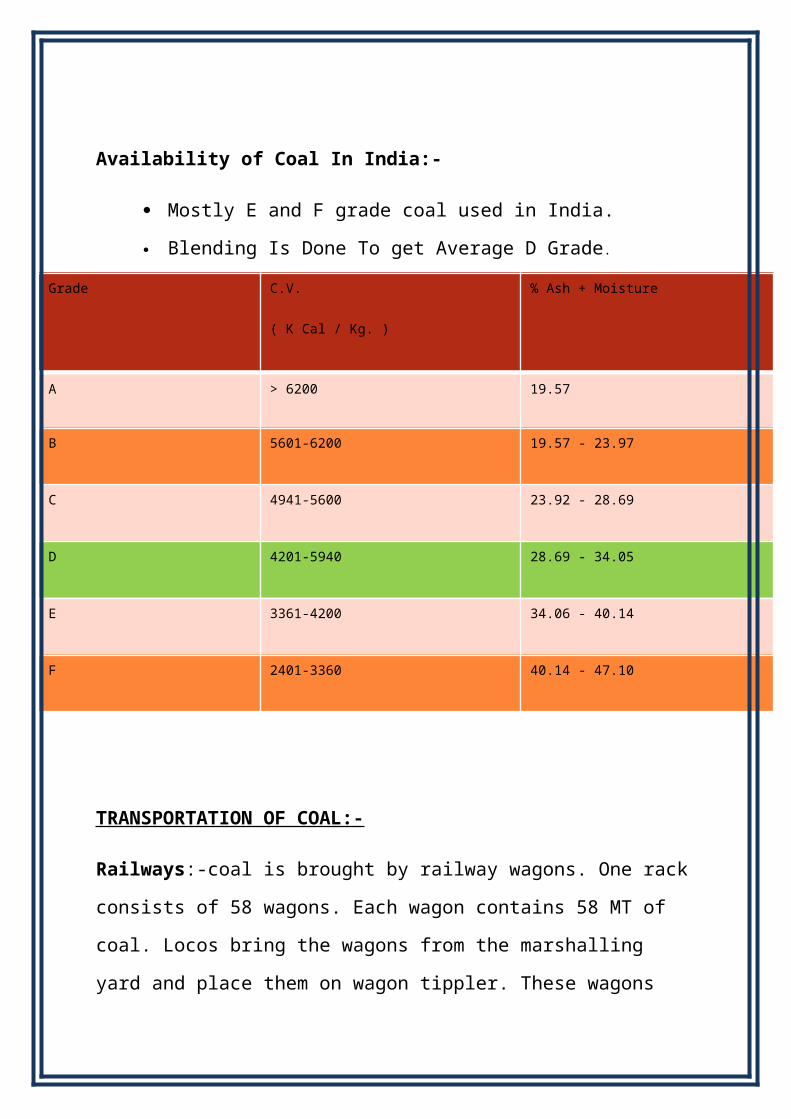
Availability of Coal In India:-
Mostly E and F grade coal used in India.
Blending Is Done To get Average D Grade.
Grade C.V.
( K Cal / Kg. )
% Ash + Moisture
A > 6200 19.57
B 5601-6200 19.57 - 23.97
C 4941-5600 23.92 - 28.69
D 4201-5940 28.69 - 34.05
E 3361-4200 34.06 - 40.14
F 2401-3360 40.14 - 47.10
TRANSPORTATION OF COAL:-
Railways:-coal is brought by railway wagons. One rack consists of 58 wagons.
Each wagon contains 58 MT of coal. Locos bring the wagons from the
marshalling yard and place them on wagon tippler. These wagons are then
unloaded with the help of wagon tippler. If these wagons are not unloaded in
stipulated time period (generally 7 hrs.), demurrage charges are levied by
railway department.
Coal Handling Plant Auxiliaries :-
Major auxiliaries of CHP:-
1. M.G.R. System
2. Vibrating Feeders
3. Conveyor Belts
4. Coal Crushers
5. Trippers
6. Electromagnetic Separators
7. Dust extraction systems
M.G.R:-
Merry go Round system. its a moving is used to unload the loaded coal wagon
below railway track at speed of 4 km/hr. From track hopper it goes on
conveyor belt via paddle feeder.
Vibrating Feeders:-
These are electromagnetic vibrating feeders or sometimes in the form of
dragging chains which are provided below the coal hoppers. This equipment is
used for controlled removal of coal from coal hoppers.
Conveyor Belts:-
These are the synthetic rubber belts which move on metallic rollers
called idlers and are used for shifting of coal from one place to other
places.The size of conveyor belt is of fallowing:-
CONVEYOR CAPACITY:- 2520 TON/Hr(max). 2100ton/hr(normal)
CONVEYOR WIDTH:- 1500MM.
CONVEYOR SPEED:-3.3M/SEC
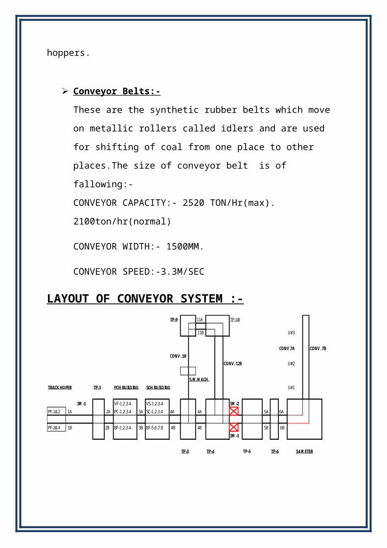
LAYOUT OF CONVEYOR SYSTEM :-

TP-9 11A TP-10
11B U#3
CONV.7A CONV. 7B
CONV. 10
CONV. 12B U#2
S/R. MACH.
TRACK HOPER TP-1 PCH BUILDING SCH BUILDING U#1
SM-1 VF-1.2.3.4 VS-1.2.3.4 SM-2
PF-1&2 1A 2A PC-1.2.3.4 3A SC-1.2.3.4 4A 4A 5A 6A
PF-3&4 1B 2B BF-1.2.3.4 3B BF-5.6.7.8 4B 4B 5B 6B
SM-3
TP-3 TP-4 TP-5 TP-6 54 METER
Coal Crushers:-
We receive the coal in the form of odd shaped lumps. These lumps are to
be crushed to required size. These lumps are crushed by coal crushers.
crusher are of two type :-
1. PRIMARY CRUSHER:- Raw coal from track hopper comes to
primary crushing house via conveyor belt after crushing in primary
crusher size of coal becomes 150 mm. This coal of 150 mm is send to
secondary crusher through conveyor belt.
2. SECONDARY CRUSHER:-
Crushed coal of 150 mm is goes to secondary crusher after being
crushed is coal becomes 20mm. After coal crushed twice it send for
further power operation.
Trippers:-
These are the motorized operated machines and are used for feeding the
coal to coal bunkers as per their requirement.
Electromagnetic Separators:-
Electromagnets are used for removing of Iron and magnetic impurities
from the coal.
Dust Extraction System:-
This system is provided in CHP for suppression of coal dust in coal
handling plant.
Operational Cycles:-
1. Normal Bunkering cycle.
2. Stacking cycle.
3. Reclaiming Cycle.
Normal Bunkering Cycle:-
Shifting of coal received from coal wagons directly to coal bunkers is
normal bunkering cycle.
Stacking Cycle:-
When there is no coal requirement at coal bunkers even then CHP has to
unload the received coal which is stacked at open ground called yard.
This is stacking cycle.
Reclaiming Cycle:-
when coal wagons are not available the requirement of coal bunkers is
fulfilled from the stacked coal this is reclaiming cycle.
Precautionary Measures before Transporting Coal
Weighing of Coal:-
Weighing of coal is carried out at wagon tippler. Weight of loaded wagon
is taken; after unloading the coal, weight of empty wagon is taken the
difference of the two will give the weight of the coal (normally 55-60
metric ton of coal come in each wagon).
Payment of Coal:-
Payment of coal is made to the coalmines as per the weighing of coal
carried out at their premises. However, if any dispute arises regarding
weighing of coal same is to be settled by the committee of both the
parties.
Stone shells:-
Sometimes stone shells are received along with coal same has to be
removed from the coal before bunkering and is done sometimes manually
or by different type of machines.
If quantum of stone shells is beyond minimum limit the cost of the coal is
recovered from the coal mines against the quantity of stone shells
received from them.
Chemical Analysis of Coal:-
Sample of coal is randomly collected from each rake by concerned
division staff and detailed chemical analysis, calculation of calorific value
is carried out and is confirmed whether it is as per agreement with the
coal mines or not.
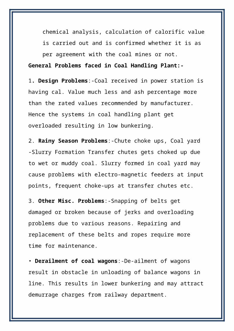
General Problems faced in Coal Handling Plant:-
1. Design Problems:-Coal received in power station is having cal. Value much
less and ash percentage more than the rated values recommended by
manufacturer. Hence the systems in coal handling plant get overloaded resulting
in low bunkering.
2. Rainy Season Problems:-Chute choke ups, Coal yard -Slurry Formation
Transfer chutes gets choked up due to wet or muddy coal. Slurry formed in coal
yard may cause problems with electro-magnetic feeders at input points, frequent
choke-ups at transfer chutes etc.
3. Other Misc. Problems:-Snapping of belts get damaged or broken because of
jerks and overloading problems due to various reasons. Repairing and
replacement of these belts and ropes require more time for maintenance.
• Derailment of coal wagons:-De-ailment of wagons result in obstacle in
unloading of balance wagons in line. This results in lower bunkering and may
attract demurrage charges from railway department.
• Oversized coal/Muddy Coal:-Oversized / muddy coal may cause damage to
the belt system, frequent choke-ups of transfer chutes and damages to the
crusher rings.
DU ST M AN A G E M E N T A T C O A L H AND LI N G P L AN T O F T.P.P .
INTRODUCTION:-
Coal fire thermal power plant sere keys to power production in the country.
They play vital role in power generation and distribution, and constitute
64.75%oftotalpower production in India. Since coal is the basic raw material
used in such power plant, so they are equipped with a large coal handling plant
(CHP) where coal transported from coal mines are stored and processed before
sending to boiler and steam generation section. A CHP may also be called
a"coal handling and preparation plant"(CHPP).At this plant, major ergonomic
concern is of dust particles which become air borne while coal storage and
processing. CHP require very large area for coal storage and processing,
therefore large scale dust generation occurs at such plant. People working here
become victim of Pneumoconiosis which is an occupational lung disease and
are attractive lung disease caused by the inhalation of dust. Thus ergonomic
design of CHP is necessary for betterment of workers and authority concern.
Since CHP require large amount of water for dust suppression, therefore
innovative methods have to be design in order to minimize use of water. Since
many thermal power plant in India facing acute shortage of water, therefore
efficient method of dust suppression and prevention is highly recommended

which uses least amount of water. The following paper discusses design of a
dust collector which discharges dust in concentrated form in order to reduce
water consumption. A part from Dust Collector, typical nozzle design is also
proposed which utilizes elegant diverging water spray for dust prevention
minimizing water wastage. Dust suppression plays vital role in improving
performance of workers and their health, hence ergonomic design of CHP is
very important issue discussed at industry level, especially at Thermal Power
Plant.
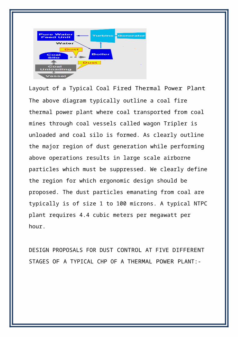
Layout of a Typical Coal Fired Thermal Power Plant
The above diagram typically outline a coal fire thermal power plant where coal
transported from coal mines through coal vessels called wagon Tripler is
unloaded and coal silo is formed. As clearly outline the major region of dust
generation while performing above operations results in large scale airborne
particles which must be suppressed. We clearly define the region for which
ergonomic design should be proposed. The dust particles emanating from coal
are typically is of size 1 to 100 microns. A typical NTPC plant requires 4.4
cubic meters per megawatt per hour.
DESIGN PROPOSALS FOR DUST CONTROL AT FIVE DIFFERENT
STAGES OF A TYPICAL CHP OF A THERMAL POWER PLANT:-
Design proposals for preventing and suppressing dust at CHP using efficient
methods. The above figure clearly depicts the design proposal for preventing
and suppressing dust at CHP using efficient methods and implementing cutting
edge technology. The given design proposal targets five different stages where
dust generation is quite large.
STAGE1
At this stage, coal transported from coal mines is brought at CHP using Wagon
Tripler and unloaded to reclaimer. Large amount of dust is generated and in
order to prevent dust, moisture addition is most efficient techniques water is
very powerful binding solvent. Directly adding moisture to coal prevents dust
from becoming air borne. Here diverging nozzles are used for moisture
addition. Diverging nozzle will allow optimum proportionate of water to be
added with coal. Since it is necessary to know exactly what amount of water to
be added as too much water will cause mud and make coal heavier, on the other
hand, too little water will be in effective in dust control.
STAGE2
Here (reclaimer stage) coal is unloaded from wagon Tripler to be reclaimed.
The area where reclaiming is done is quite large and hence water addition will

be futile. Also wind play devastating role in increasing dust. Thus wind is the
major factor .So wind speed i s c o n t r o l l e d in order to prevent dust to
become air borne. Wind shield net or wind break forest is provided in order to
reduce dust generation.
STAGE3
Reclaimer piles up the coal at a largest or age area and form as stacker or coal
pile. While doing this, large amount of dust is generated. Also coal stacker is a
constant source of airborne dust particles. Therefore it is necessary to suppress
dust generation. At this stage surface compaction method is used to suppress
dust using 6-12% water solution of very good binding substance which binds
the coal dust and prevent it from becoming airborne. Moisture addition is done
at this stage using well designed spray which allow scone trolled flow of
solution over coal pile in order to properly suppress dust without affecting the
quality of coal.
STAGE4
This stage is major area of concern because dust particle size is a slow as1-
10microns.Therefore this stage requires a suitable, innovative and efficient
technique of dust suppression. Since moisture addition is futile exercise,
therefore we develop wet dust collector which can reduce dust concentration as
lowas1%in the concerned area. Dust collector is very elegant device which
discharges dust in concentrated form reducing water consumption. Even for
suppressing1mmthick dust layer, we require large amount of water, but dust
collector with minimum use of water, suppresses large amount of dust. The
following section discusses design of wet centrifugal dust collector with
automatic discharge for suppressing dust at this stage. Here processed coal is
transferred from coal stack through convey or to relay section, hence large
amount of dust is generated which can be suppress seducing dust collector.

STAGE5
Last stage is unloading of coal from relay section and transfer to the boiler
section. At this stage, usual method of moisture addition is sufficient in cess
mall amount of dust generates which can easily be suppress using proper
amount of moisture addition. At this stage also, diverging nozzles of optimum
diameter are used for proper water spray.
D ES I G N O F A W E T C E N T R I F U G A L D U S T C O L L E C T O R :-
Centrifugal collectors use cyclonic action to separate dust particles from the
gas stream. In a typical cyclone, the dust gas stream enters at an angle and is
spun rapidly. The centrifugal force created by the circular flow throws the dust
particles toward the wall of the cyclone. After striking the wall, these particles
fall in to a hopper located underneath.
The most common types of centrifugal or inertial collectors in use today are:-
1) Single-cyclone separators
2) Cyclone Multiple-separators
3) Secondary Air Flow Separators

A typical wet centrifugal dust collector uses scrubbing effect of water to
suppress dust. Water is very good binding substance for dust and therefore it is
used as scrubbing element. This device applies the principle of film formation
over the dust layer and confines dust particles leaving fresh air to escape. The
power rating of motor varies as per requirement. This device uses the principle
of dynamic precipitation technique in which very high suction pressure suck the
dusty air and allow to centrifuge through it. Centrifugal action separates dust
from fresh air and fresh air is allowed to escape from to here from dust
collector.
The dust collector has a small tank full of water which has two valves. These
two springs loaded valves are operated to allow passage of concentrated dust
and automatic filling of fresh water using sensors. These sensors sense the
concentration level of dust in the container and when it goes beyond 90%,it
opens the discharge valve. This remains open until total discharge of
concentrated dust occurs from the tank. At the same time, it opens inlet valve
to allow fresh water to fill up.
The dust collector uses automatic discharge technique and hence save time
form annual operations for discharging and refilling. Also discharge is recycled
in order to have minimum water wastage. This centrifugal dust collector is very
efficient and requires minimum amount of water since it discharges dust in
concentrated form. Taking atypical case of a NTPC plant which uses 4.4cubic
meter per mega watt per hour, assuming power production of 1000MW, total
water consumption will be4400 million cubic meter water. This is huge amount
of water which is utilized at such plant. But with the above mentioned
techniques, if implemented properly can save large amount of water and hence
reduce chances of a cute water shortage.
R ES U L T SAND CONCLU S I O N :-
A wet centrifugal dust collector with automatic discharge can reduce airborne
dust particle sand minimize water wastage. Al soother methods of dust
collection reduce dust and water was taigas discussed earlier. This has great
impact not only at workplace butyl so in environment. Proper implementation
of dust suppression and prevent in methods reduces health hazards of workers,
employees and people residing nearby. Since current situation demands eco-
friendly method soft dust suppression without much water wastage, above
mentioned ergonomic designs are noteworthy.
A REPORT OF THEVOCATIONAL TRAINING ON
“COAL HANDLING PLANT”
FOR THE PERIOD OF FOUR WEEKS FROM 15.06.15 TO 17.07.15
AT
ANPARA THERMAL POWER STATION ANPARA, SONEBHADRA U.P.
OF UPRVUNL
BY
RAJAT VERMA
B.tech (Elect.Engg) IIIrd Year
TO
SURYA PRAKASH PAL A. S. MISHRA
ASSISTANT ENGINEER EXCUTIVE ENGINEER

Turbine used in ATPS
Three phase synchronous generator (210MW) used at ATPS
:


