
11/10/2014
1
WEBINAR
Code Requirements for Nuclear Safety-Related Concrete Structures (ACI 349)
Session 2 – Structural Systems or Elements
This Webinar is sponsored by ACI. The ideas expressed, however, are those of the speakers and do not necessarily reflect the views of ACI or its
committees. The audience is expected to exercise judgment as to the appropriate application of the information.
Please adjust your audio level at this time.
WEBINAR
• For continuing education credit, attendees must purchase the ACI webinar titled “Nuclear Safety-Related Concrete Structures” for $200 ACI members/$250 nonmembers. Attendees that log in with full name and email address, and attend the entire webinar, will receive certificates for each part of the four-part webinar series. Totaling 5 Professional Development Hours (PDH) of continuing education credit. Visit www.ACIeLearning.org and login to access the ACI eLearning site.
• For site license purchasers, if you view the webinar within a group, your name, email address and signature must appear on your organization’s group attendance sign-in sheet.
• Corporate group discounts are available for those attending the live webinar by contacting Claire Hiltz at [email protected].
• Questions related to specific materials, methods, and services will be addressed at the conclusion of this presentation.

11/10/2014
2
WEBINAR
American Concrete Institute is a Registered Provider with The American Institute of Architects Continuing Education Systems (AIA/CES). Credit(s) earned on completion of this eLearning course will be reported to AIA/CES for AIA members.
The eLearning course based on this webinar is registered with AIA/CES for continuing professional education. As such, it does not include content that may be deemed or construed to be an approval or endorsement by the AIA of any material of construction or any method or manner of handling, using, distributing, or dealing in any material or product.
• The American Institute of Architects has approved this course for 1 AIA/CES LU/HSW Learning Unit.
The American Institute of Architects has approved this course for 1 AIA/CES LU/HSW learning unit.
ACI is an AIA/CES registered provider.
WEBINAR
• Recognize the scope of structures covered by ACI 349.
• Identify the difference between ACI 318-08 and ACI 349-13.
• Identify the material requirements for design in accordance with ACI 349.
• Understand the basic assumptions and design philosophy behind reinforced concrete design according to ACI 349.
• Identify design and detailing requirements that are specific to nuclear construction.
• Become acquainted with ACI Committee 349 documents:
1) 349.1R-07, Reinforced Concrete Design for Thermal Effects on Nuclear Power Plant Structures;
2) 349.2R-07, Guide to the Concrete Capacity Design (CCD) Method—Embedment Design Examples; and
3) 349.3R-02, Evaluation of Existing Nuclear Safety-Related Concrete Structures.
Learning Objectives:
Code Requirements for Nuclear Safety-Related Concrete Structures (ACI 349)Session 2 – Structural Systems or Elements
Code Requirements for Nuclear Safety-Related Concrete Structures (ACI 349)Session 2 – Structural Systems or Elements

11/10/2014
3
WEBINAR
Dr. Javeed MunshiJaveed Munshi is Senior Principal Engineer and Fellow at Bechtel PowerCorp. in Frederick MD. He has over 25 years of experience in the design,evaluation, and construction of concrete structures, including heavy industrial(fossil, nuclear and renewable) power structures, bridges, buildings,underground structures (tunnels), and environmental concrete structures. Hehas served on expert panels and peer reviewed many projects. He hascontributed to eight books/design aids for concrete, and published over 70papers. He has conducted concrete design seminars and training for theAmerican Concrete Institute (ACI), the Portland Cement Association (PCA),and the Concrete Reinforcing Steel Institute (CRSI). He is Fellow of theAmerican Concrete Institute (ACI), Fellow of the American Society of CivilEngineers (ASCE), and Fellow of the Structural Engineering Institute (SEI).He is also a licensed professional engineer (PE) in New York, Wisconsin andMaryland and a licensed Structural Engineer (SE) in Illinois. He is a memberof ACI 349 and ASME Section III, Div 2. Committees for concrete nuclearstructures.
WEBINAR
Herman L. GravesHerman L. Graves, III, P.E., FACI is a consulting engineer. He worked as aSenior Structural Engineer at the U.S. Nuclear Regulatory Commission(NRC) from 1980 to 2013, where he formulated and managed researchprograms related to nuclear civil/structural engineering.
Mr. Graves has been an ACI member for more than 30 years. He is theimmediate past chairman of ACI Committee 349, “Concrete NuclearStructures,” a member of ACI Committee 355, “Anchorage to Concrete,” anda member of the Committee on Awards for Papers. He was named a Fellowof ACI in 2008, and has contributed to various ACI publications as an authorand technical reviewer. He is a licensed Professional Engineer inWashington, DC and Maryland.

11/10/2014
1
WEBINAR
CODE REQUIREMENTS FOR NUCLEAR SAFTEY RELATED CONCRETE
STRUCTURES
Session 2
By Javeed Munshi, PhD., P.E., F. ACI, F. ASCE
Partha Ghosal, M.S., P.E.
Herman L. Graves, III, M.S.,P.E., F. ACI
WEBINAR
2
CHAPTER 11SHEAR & TORSION

11/10/2014
2
WEBINAR
3
SHEAR & TORSIONSHEAR & TORSION
Slabs Without Shear Reinforcement
Shear Reinforcement – U Stirrups
Deep Beams
Strut and Ties
Brackets
Footings
3
WEBINAR
4
SHEAR
• Factored Shear Forces Vu
Vu / ≤ Vn
where = 0.85
Reference: Sec. 11.1
11/10/2014
3
WEBINAR
5
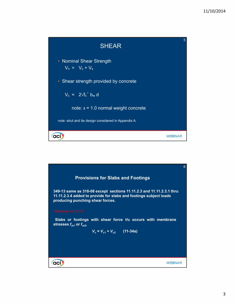
SHEAR
• Nominal Shear Strength
Vn = Vc + Vs
• Shear strength provided by concrete
Vc = 2fc´ bw d
note: ּג = 1.0 normal weight concrete
note: strut and tie design considered in Appendix A.
WEBINAR
6
349-13 same as 318-08 except sections 11.11.2.3 and 11.11.2.3.1 thru 11.11.2.3.4 added to provide for slabs and footings subject loads producing punching shear forces.
Provisions for Slabs and Footings
Reference 11.11.2.3
Slabs or footings with shear force Vu occurs with membranestresses fm1 or fm2,
Vc = Vc1 + Vc2 (11-34a)

11/10/2014
4
WEBINAR
7SHEAR
WEBINAR
8SHEAR

11/10/2014
5
WEBINAR
9
Fig. —Concrete shear strength in presence of membrane tensile stresses.
Punching Shear
WEBINAR
10
Vc1 and Vc2 are:For fm1 tensile and ≤ 0.9ρ1′fy
except factor (2 + 4/βc) shall ≤ 4. For fm1 tensile and > 0.9ρ1′fy
For fm1 compressive and ≥ 125 psi, Vc1 shall be taken as Vc, calculated in accordance with 11.11.2.2 except that in Eq. (11-34), fm1 and b1′ shall be used in place of fpc and bo, respectively.
For fm1 compressive and < 125 psi, Vc1 shall be taken as Vc calculated in accordance with 11.11.2.1 except that b1′ shall be used in place of bo.
Punching Shear
11/10/2014
6
WEBINAR
11
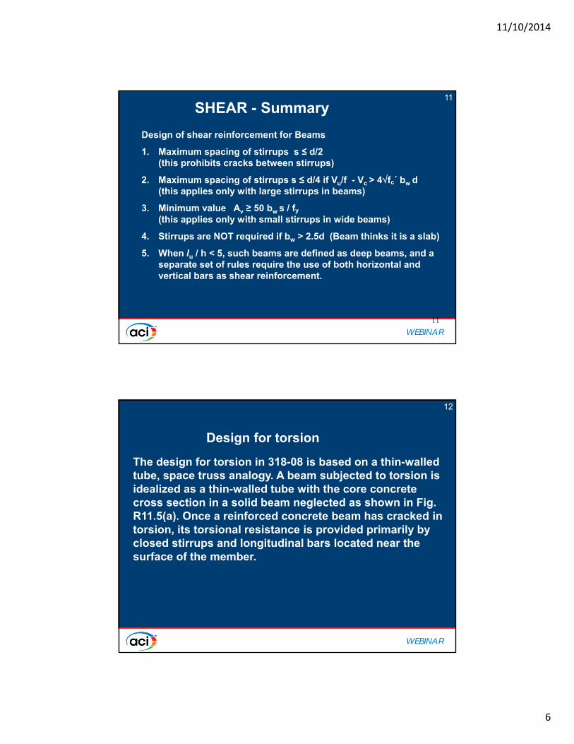
SHEAR - Summary
11
Design of shear reinforcement for Beams
1. Maximum spacing of stirrups s ≤ d/2 (this prohibits cracks between stirrups)
2. Maximum spacing of stirrups s ≤ d/4 if Vu/f - Vc > 4fc´ bw d (this applies only with large stirrups in beams)
3. Minimum value Av ≥ 50 bw s / fy
(this applies only with small stirrups in wide beams)
4. Stirrups are NOT required if bw > 2.5d (Beam thinks it is a slab)
5. When lu / h < 5, such beams are defined as deep beams, and a separate set of rules require the use of both horizontal and vertical bars as shear reinforcement.
WEBINAR
12
The design for torsion in 318-08 is based on a thin-walled tube, space truss analogy. A beam subjected to torsion is idealized as a thin-walled tube with the core concrete cross section in a solid beam neglected as shown in Fig. R11.5(a). Once a reinforced concrete beam has cracked in torsion, its torsional resistance is provided primarily by closed stirrups and longitudinal bars located near the surface of the member.
Design for torsion

11/10/2014
7
WEBINAR
13
Fig. 11.5—(a) Thin-walled tube; (b) area enclosed byshear flow path.
WEBINAR
14
Closed Ties or Stirrups
1.3 ld
Torsion
Full Depth
9 kip Max
Closed Tie or Stirrup

11/10/2014
8
WEBINAR
15
1. One piece with overlapping 90 or 135 degree end hooks around a longitudinal bar.
2. Two piece with a Class B splice.
3. Neither of the above two are suited for high torsion.
4. Two piece closed stirrup used for torsion.
5. Section 12.13.5 gives lap splice requirements for double U-stirrups or ties (1.3 ld)
6. If 1.3 ld cannot fit, use full splice and limit force in each leg to within 9 kips (18 in. min. depth required)
Closed Ties or Stirrups
WEBINAR
16
CHAPTER 12DEVELOPMENT AND SPLICE MOSTLY SIMILAR TO ACI 318

11/10/2014
9
WEBINAR
17
In order to develop bars, bars pulled from concrete encasement or push against concrete:
Failure Modes from Splitting Cracks:
Corner Splitting Bottom Splitting Face Splitting
Need more edge distance Need more bottom cover Bars too close together
P P
Bar Development
WEBINAR
18
Factors ,, and = 1 with the following exceptions:
= location factor = 1.3 if more than 12 in of concrete is cast below bar. = bar epoxy coating factor = 1.2 to 1.5 if bars are coated. = bar size factor = 0.8 for #6 and smaller bars. = concrete density factor = 1.3 if lightweight concrete is used.
Bar Development

11/10/2014
10
WEBINAR
19
Grade 60 Bars in fc’ = 4000 psi concrete [Bottom-cast Bars] ,, and λ = 1
Bar size Shortest possible “Usual” case “Worst” case
11
10
9
8
7
6
5
4 Multiply these values by 1.3 for Top-cast Bars
3
12 20 30 40 50 60 70 80 90
Basic Development Length d (in)
Bar Development
WEBINAR
20
Hooked Bars Compression Bars
dh = (1200db/fc’)(fy/60000) dc = 0.02dbfy/fc’ 0.0003dbfy > 8 in
For Grade 60 Bars in Concrete of fc’ = 4000 psi
ldh dh dc Asfy
26.8 #11 26.824.1 #10 24.121.4 # 9 21.419.0 # 8 19.0
Asfy 16.6 # 7 16.6 dc
14.2 # 6 14.2 11.9 # 5 11.99.5 # 4 9.58.0 # 3 8.0
Multiply by 0.7 if side concrete Multiply by 0.75 if bars are cover is more than 2.5 in. enclosed by transverse spiral
No increase is necessary for dh or dc if bars are top-cast bars.
Bar Development

11/10/2014
11
WEBINAR
21
1. At least one-third of bottom bars required for positive moment must be extended at least 6 in into supports of simply supported beams.
2. At least one-fourth of bottom bars required for positive moment must be extended at least 6 in into supports of continuous beams.
3. At least one-third of top bars required for negative moment must extend beyond the Point of Inflection associated with the negative moment.
4. Continuing bars for flexure must extend beyond the point at which they are required for a distance at least 12db or the depth
of the member d.
Bar Development
WEBINAR
22
1. Lap splices are restricted to bars #11 and smaller.
2. Class B Tension Splice length shall be 1.3d .
3. Class A Tension Splice length = 1.0 d may be used if:a) Fewer than half of bars are spliced at same
location, or b) Bar stress being developed is less than fy/2.
4. Splices shall be staggered at least 24 in
5. Compression Splice Length shall be (0.0005fy)db or (0.0009fy – 24)db but not less than 12 in.
6. Compression splices within spiral columns may be 75% as long as 5 above, but not less than 12 in.
Bar Splices

11/10/2014
12
WEBINAR
23
Exception for Gr 75 and Gr 80
WEBINAR
24
Mechanical Splice

11/10/2014
13
WEBINAR
25
Mechanical Splice
WEBINAR
26
Splice

11/10/2014
14
WEBINAR
27
Mechanical Anchorage
WEBINAR
28
Mechanical or Welded Splice

11/10/2014
15
WEBINAR
29
Mechanical or Welded Splice
WEBINAR
30
1. No. 14 and 18 bars cannot be bundled in beams.
2. If individual bars are cut off within a span, they should be staggered by 40 db.
3. For spacing and cover, a unit of bundled bar must be treated as a single bar with an area equal to the total area of all the bars.
4. A maximum of 4 bars may be bundled.
5. Bundled bars must be enclosed within stirrups or ties.
6. Development length based on individual bars increased by 20% for 3 bar bundle and 33% for 4 bar bundle.
Bundled Bars

11/10/2014
16
WEBINAR
31
Noncontact lap splices shall be transversely spaced within the smaller of 1/5th required splice length and 6 in.
Noncontact Lap
WEBINAR
32
CHAPTER 13TWO WAY SLABS
SAME AS IN ACI 318

11/10/2014
17
WEBINAR
33
One-way slab
Beams provide support for slab to act only
in one direction between beams.
Two-way slab
Beams along all four edges permit slab to
act in both directions between parallel
beams.
Flat plate
Absence of beams forces slab to act in both
directions between lines of columns.
WEBINAR
34

11/10/2014
18
WEBINAR
35
A
B
TWO-WAY DEFLECTION
WEBINAR
36

11/10/2014
19
WEBINAR
37
Frame 1 Frame 2 Frame 3 Frame 4
Col. Strip
Col. Strip
Col. Strip
Slab Strip
Col. Strip Col. Strip
Slab Strip
Frame A
Frame B
Frame C
Frame D
Direct Design and Equivalent Frame Method
WEBINAR
38
1
1
2
2
c1
c1
hs
Col.
Col.
Col.
Torsion member
c2
Torsion constant C = (1-0.63hs/c1)hs3c1/3
Torsion stiffness Kt = 9EcC /[2(1-c2/ 2)3]
Slab-beam value of I is Islab = (1-c2/2 )2c2c13 /12
Equivalent column stiffness = Ke and 1/Ke = 1/Kt + 1/(4Ec Islab) (9.3) The joint shown has 2 torsional members and 2 column members.
Equivalent Frame Procedure

11/10/2014
20
WEBINAR
39
Equivalent Frame Procedure
ACI318-05, Section 13.7.6 – Arrangement of live load
* Each frame extends from slab centerline to slab centerline or edge of slab.
* Shears and moments along each frame must be determined. Spreadsheet program can be adapted for the analysis of each span of each frame.
* When wL < 0.75wD, assume total load wu acts simultaneously on all spans.
* When wL > 0.75wD, for positive moments assume that 0.75wu acts everywhere.
* When wL > 0.75wD, for negative moments assume that wu acts in span, but 0.75 wu acts on adjacent spans.
WEBINAR
40

11/10/2014
21
WEBINAR
41
CHAPTER 14WALL DESIGN
SIMILAR TO ACI 318
WEBINAR
42
Wall Design

11/10/2014
22
WEBINAR
43
Walls
• Design for Shear
3 cases to consider:Vu ≤ Vc /2
Vc /2 < Vu ≤ Vc
Vu > Vc
WEBINAR
44
CHAPTER 15 FOOTINGS
349-13 SAME AS 318-08

11/10/2014
23
WEBINAR
45
Foundation SystemsFoundation Systems
• Basic types of foundation system• Wall footing• Isolated spread footing• Combined footing• Strap footing• Pile footing• Raft or Mat footing
45
WEBINAR
46
Footing Design ProcedureFooting Design Procedure
• Calculate footing size based on allowable soil bearing capacity using un-factored combination of loads
• Consider footing thickness and calculate average effective "d"Ave. d ≈ h - 4.0“
• φ factor to check shear strengthφ = 0.85 [Sec. 9.3.2.3]
Reference: Sec. 15.2, 9.3
46

11/10/2014
24
WEBINAR
47
CHAPTER 16PRECAST
WEBINAR
48
GeneralGeneral
16.1—Scope16.1.1 Provisions of Chapter 16 shall apply for design ofprecast concrete members defined as concrete elements cast elsewhere than their final position in the structure.
All provisions of this Code not specifically excluded, and not in conflict with provisions of Chapter 16, shall apply to precast concrete.
Note: ACI 349-13 fully adopted 318-08 guidance.
48

11/10/2014
25
WEBINAR
49
CHAPTER 17COMPOSITE CONCRETE
FLEXURE MEMBERS
WEBINAR
50
GeneralGeneral
17.1—Scope17.1.1 Provisions of Chapter 17 shall apply for design ofcomposite concrete flexural members defined as precast and/or cast-in-place concrete elements constructed in separateplacements but so interconnected that all elements respondto loads as a unit.
All provisions of this code shall apply to compositeconcrete flexural members, except as specifically modifiedin Chapter 17.
50

11/10/2014
26
WEBINAR
51
GeneralGeneral
• Horizontal shear strength (ties)
• Vnh shall be taken equal to (260 + 0.6ρvfy)λbvd, ≤ 500bvd, where λ is 1.0 for normal weight concrete and ρv is Av/(bvs)
Reference: Section 17.5.3.3
51
WEBINAR
52
CHAPTER 18PRESTRESSED CONCRETE

11/10/2014
27
WEBINAR
53
Chapter 18 ,continued
• The commentary on ACI 318 is applicable to this chapter except references to lightweight concrete and other prestressed reinforcing systems n.a. to nuclear safety related structures are omitted.
WEBINAR
54Chapter 18 ,continued
Section 18.1.4 - Service load conditions are defined to be the load combinations of Section 9.2.1 of 349-13 with load factors taken as unity:
(9-1) U = (D+F+RO) + TO
(9-2) U = (D+F+ TO + RO) + (L+H) + CCR + (Lr or S or R)
(9-4) U = (D+F+RO) + (L+H+ Eo)
(9-5) U = (D+F+RO) + (L+H+ W)

11/10/2014
28
WEBINAR
55
Chapter 18, cont.
• Section 18.13- Post-tensioned tendon anchorage zones
• Same as 318-08 except in Section 18.13.4.2
• ּג = 1.0
WEBINAR
56
CHAPTER 19SHELLS

11/10/2014
29
WEBINAR
57
Chapter 19 of ACI 318-08 is intended to provide design provisions for the wide range of shell forms expected to be used for commercial structures. These include thin shells, folded plates, and ribbed shells to name a few. In nuclear safety related concrete structures, the shell forms usually encountered are limited to basic cylinders with dome shapes, having thicknesses not less than 12 in.
WEBINAR
58
Chapter 19, continued
19.1 – Scope and Definitions
19.1.1 Chapter 19 shall apply for design of shell concreteStructures having thicknesses equal to or greater than 12 inches (2.54cm)
11/10/2014
30
WEBINAR
59
Chapter 19, continued
19.2.10—Model tests
19.2.10.1 Model tests may be used in support of the
design if they are planned and executed by individuals or laboratories with experience in physical testing.
19.3-Design strength of materials
Specified compressive strength of concrete fc´ at 28
days ≥ 3000psi
WEBINAR
Thank you
For the most up-to-date information please visit the American Concrete Institute at:
www.concrete.org


