
1
COGENERATION
A simple process-heating plant.
Many industries require energy input in the form of heat, called process
heat. Process heat in these industries is usually supplied by steam at 5 to
7 atm and 150 to 200°C. Energy is usually transferred to the steam by
burning coal, oil, natural gas, or another fuel in a furnace.
Industries that use large amounts
of process heat also consume a
large amount of electric power.
It makes sense to use the already-
existing work potential to produce
power instead of letting it go to
waste.
The result is a plant that produces
electricity while meeting the
process-heat requirements of
certain industrial processes
(cogeneration plant)
Cogeneration: The production of more than one useful form of energy
(such as process heat and electric power) from the same energy source.

2 An ideal cogeneration plant.
Utilization
factor
• The utilization factor of the
ideal steam-turbine
cogeneration plant is
100%.
• Actual cogeneration plants
have utilization factors as
high as 80%.
• Some recent cogeneration
plants have even higher
utilization factors.
3
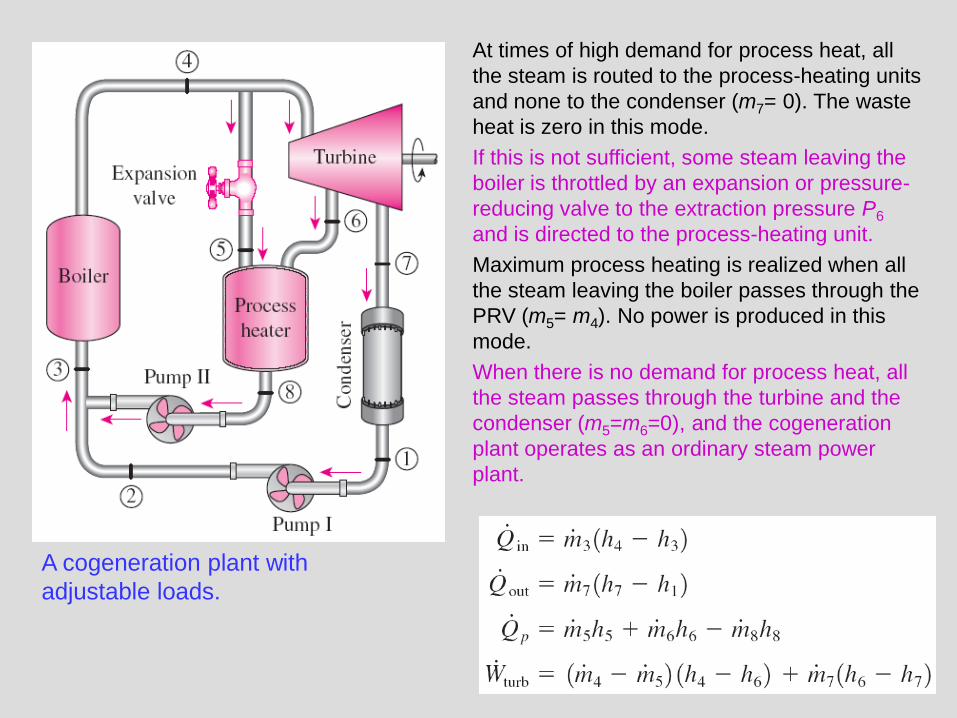
A cogeneration plant with
adjustable loads.
At times of high demand for process heat, all
the steam is routed to the process-heating units
and none to the condenser (m7= 0). The waste
heat is zero in this mode.
If this is not sufficient, some steam leaving the
boiler is throttled by an expansion or pressure-
reducing valve to the extraction pressure P6
and is directed to the process-heating unit.
Maximum process heating is realized when all
the steam leaving the boiler passes through the
PRV (m5= m4). No power is produced in this
mode.
When there is no demand for process heat, all
the steam passes through the turbine and the
condenser (m5=m6=0), and the cogeneration
plant operates as an ordinary steam power
plant.

4
COMBINED GAS–VAPOR POWER CYCLES
• The continued quest for higher thermal efficiencies has resulted in rather
innovative modifications to conventional power plants.
• A popular modification involves a gas power cycle topping a vapor power cycle,
which is called the combined gas–vapor cycle, or just the combined cycle.
• The combined cycle of greatest interest is the gas-turbine (Brayton) cycle topping
a steam-turbine (Rankine) cycle, which has a higher thermal efficiency than
either of the cycles executed individually.
• It makes engineering sense to take advantage of the very desirable
characteristics of the gas-turbine cycle at high temperatures and to use the high-
temperature exhaust gases as the energy source for the bottoming cycle such as
a steam power cycle. The result is a combined gas–steam cycle.
• Recent developments in gas-turbine technology have made the combined gas–
steam cycle economically very attractive.
• The combined cycle increases the efficiency without increasing the initial cost
greatly. Consequently, many new power plants operate on combined cycles, and
many more existing steam- or gas-turbine plants are being converted to
combined-cycle power plants.
• Thermal efficiencies over 50% are reported.

5 Combined gas–steam power plant.

6
Example 1: Consider a steam power plant operating on the simple ideal Rankine
cycle. Steam enters the turbine at 3 MPa and 350°C and is condensed in the
condenser at a pressure of 75 kPa. Determine the thermal efficiency of this cycle.

7

8

9
Example 2: A steam power plant operates on the cycle shown below. If the
isentropic efficiency of the turbine is 87 percent and the isentropic efficiency of the
pump is 85 percent, determine (a) the thermal efficiency of the cycle and (b) the net
power output of the plant for a mass flow rate of 15 kg/s.
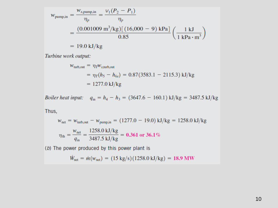
10

11
Example 3: Consider a steam power plant operating on the ideal regenerative
Rankine cycle with one open feedwater heater. Steam enters the turbine at 15
MPa and 600°C and is condensed in the condenser at a pressure of 10 kPa.
Some steam leaves the turbine at a pressure of 1.2 MPa and enters the open
feedwater heater. Determine the fraction of steam extracted from the turbine and
the thermal efficiency of the cycle.

12

13

14
Example 4: Consider a steam power plant that operates on an ideal reheat–
regenerative Rankine cycle with one open feedwater heater, one closed feedwater
heater, and one reheater. Steam enters the turbine at 15 MPa and 600°C and is
condensed in the condenser at a pressure of 10 kPa. Some steam is extracted from the
turbine at 4 MPa for the closed feedwater heater, and the remaining steam is reheated
at the same pressure to 600°C. The extracted steam is completely condensed in the
heater and is pumped to 15 MPa before it mixes with the feedwater at the same
pressure. Steam for the open feedwater heater is extracted from the low-pressure
turbine at a pressure of 0.5 MPa. Determine the fractions of steam extracted from the
turbine as well as the thermal efficiency of the cycle.

15

16

17

Chapter 11
REFRIGERATION CYCLES
Copyright © The McGraw-Hill Companies, Inc. Permission required for reproduction or display.
Thermodynamics: An Engineering Approach Seventh Edition
Yunus A. Cengel, Michael A. Boles
McGraw-Hill, 2011

19
REFRIGERATORS AND
HEAT PUMPS
The objective of a refrigerator is to remove heat
(QL) from the cold medium; the objective of a heat
pump is to supply heat (QH) to a warm medium.
The transfer of heat from a low-temperature
region to a high-temperature one requires
special devices called refrigerators.
Another device that transfers heat from a
low-temperature medium to a high-
temperature one is the heat pump.
Refrigerators and heat pumps are essentially
the same devices; they differ in their
objectives only.
for fixed values of
QL and QH

20
THE REVERSED CARNOT CYCLE
Schematic of a
Carnot refrigerator
and T-s diagram
of the reversed
Carnot cycle.
Both COPs increase as
the difference between the
two temperatures
decreases, that is, as TL
rises or TH falls.
The reversed Carnot cycle is the most efficient refrig. cycle operating between TL and TH.
It is not a suitable model for refrigeration cycles since processes 2-3 and 4-1 are not practical
because Process 2-3 involves the compression of a liquid–vapor mixture, which requires a
compressor that will handle two phases, and process 4-1 involves the expansion of high-
moisture-content refrigerant in a turbine.

21
THE IDEAL VAPOR-COMPRESSION
REFRIGERATION CYCLE
The vapor-compression refrigeration cycle is the ideal model for refrigeration
systems. Unlike the reversed Carnot cycle, the refrigerant is vaporized completely
before it is compressed and the turbine is replaced with a throttling device.
Schematic and T-s diagram for the ideal vapor-compression refrigeration cycle.
This is the most widely used cycle for refrigerators, A-C systems, and heat pumps.
22
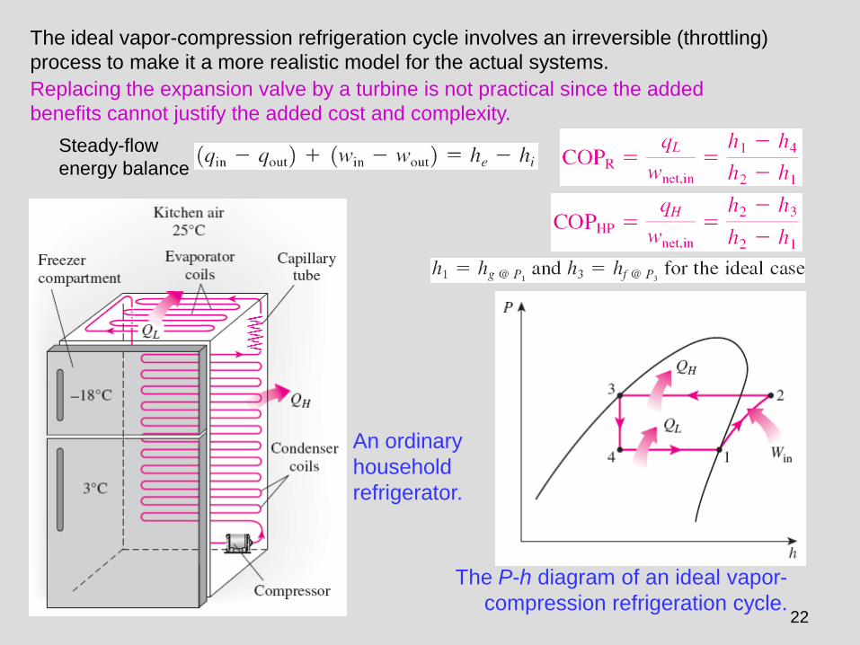
An ordinary
household
refrigerator.
The P-h diagram of an ideal vapor-
compression refrigeration cycle.
The ideal vapor-compression refrigeration cycle involves an irreversible (throttling)
process to make it a more realistic model for the actual systems.
Replacing the expansion valve by a turbine is not practical since the added
benefits cannot justify the added cost and complexity.
Steady-flow
energy balance

23
ACTUAL VAPOR-COMPRESSION
REFRIGERATION CYCLE An actual vapor-compression refrigeration cycle differs from the ideal one owing
mostly to the irreversibilities that occur in various components, mainly due to fluid
friction (causes pressure drops) and heat transfer to or from the surroundings.
Schematic and
T-s diagram for
the actual
vapor-
compression
refrigeration
cycle.
DIFFERENCES
Non-isentropic compression
Superheated vapor at evaporator exit
Subcooled liquid at condenser exit
Pressure drops in condenser and evaporator
The COP decreases as a result
of irreversibilities.

24
SECOND-LAW ANALYSIS OF VAPOR-
COMPRESSION REFRIGERATION CYCLE
The maximum COP of a refrigeration cycle operating
between temperature limits of TL and TH
Actual refrigeration cycles are not as efficient as ideal ones like the Carnot cycle
because of the irreversibilities involved. But the conclusion we can draw from Eq.
11–9 that the COP is inversely proportional to the temperature difference TH - TL
is equally valid for actual refrigeration cycles.
The goal of a second-law or exergy analysis of a refrigeration system is to
determine the components that can benefit the most by improvements.
This is done identifying the locations of greatest exergy destruction and the
components with the lowest exergy or second-law efficiency.
Exergy destruction in a component can be determined directly from an exergy
balance or by using
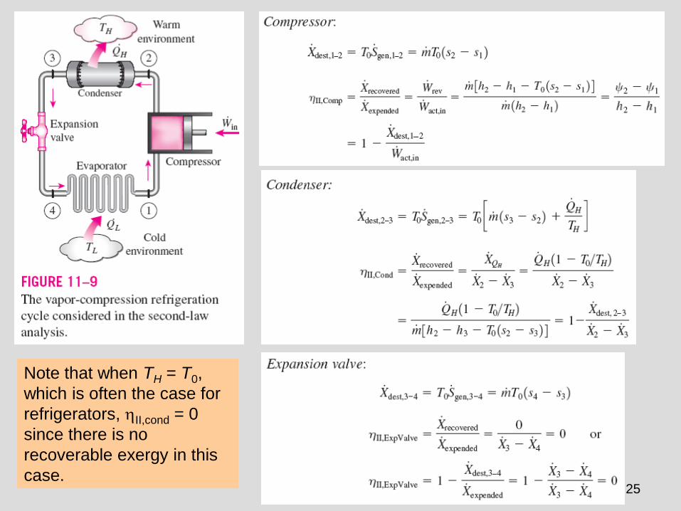
25
Note that when TH = T0,
which is often the case for
refrigerators, II,cond = 0
since there is no
recoverable exergy in this
case.

26
The exergy rate associated
with the withdrawal of heat
from the low-temperature
medium at TL at a rate of QL
This is equivalent to the power that can be
produced by a Carnot heat engine receiving heat
from the environment at T0 and rejecting heat to
the low temperature medium at TL at a rate of QL.
Note that when TL = T0, which is often the case for heat pumps,
II,evap = 0 since there is no recoverable exergy in this case.

27
This second-law efficiency definition accounts for all
irreversibilities associated within the refrigerator, including the
heat transfers with the refrigerated space and the environment.
Total exergy
destruction
Second-law (exergy) efficiency
T0 = TH for a
refrigeration cycle

28
SELECTING THE RIGHT REFRIGERANT • Several refrigerants may be used in refrigeration systems such as
chlorofluorocarbons (CFCs), ammonia, hydrocarbons (propane, ethane, ethylene, etc.), carbon dioxide, air (in the air-conditioning of aircraft), and even water (in applications above the freezing point).
• R-11, R-12, R-22, R-134a, and R-502 account for over 90 percent of the market.
• The industrial and heavy-commercial sectors use ammonia (it is toxic).
• R-11 is used in large-capacity water chillers serving A-C systems in buildings.
• R-134a (replaced R-12, which damages ozone layer) is used in domestic refrigerators and freezers, as well as automotive air conditioners.
• R-22 is used in window air conditioners, heat pumps, air conditioners of commercial buildings, and large industrial refrigeration systems, and offers strong competition to ammonia.
• R-502 (a blend of R-115 and R-22) is the dominant refrigerant used in commercial refrigeration systems such as those in supermarkets.
• CFCs allow more ultraviolet radiation into the earth’s atmosphere by destroying the protective ozone layer and thus contributing to the greenhouse effect that causes global warming. Fully halogenated CFCs (such as R-11, R-12, and R-115) do the most damage to the ozone layer. Refrigerants that are friendly to the ozone layer have been developed.
• Two important parameters that need to be considered in the selection of a refrigerant are the temperatures of the two media (the refrigerated space and the environment) with which the refrigerant exchanges heat.

29
HEAT PUMP SYSTEMS The most common energy source for heat pumps is atmospheric air (air-to- air systems).
Water-source systems usually use well water and ground-source (geothermal) heat pumps use earth as the energy source. They typically have higher COPs but are more complex and more expensive to install.
Both the capacity and the efficiency of a heat pump fall significantly at low temperatures. Therefore, most air-source heat pumps require a supplementary heating system such as electric resistance heaters or a gas furnace.
Heat pumps are most competitive in areas that have a large cooling load during the cooling season and a relatively small heating load during the heating season. In these areas, the heat pump can meet the entire cooling and heating needs of residential or commercial buildings. A heat pump can be used to heat a house in
winter and to cool it in summer.

30
INNOVATIVE VAPOR-COMPRESSION
REFRIGERATION SYSTEMS
• The simple vapor-compression refrigeration cycle is the most widely used
refrigeration cycle, and it is adequate for most refrigeration applications.
• The ordinary vapor-compression refrigeration systems are simple,
inexpensive, reliable, and practically maintenance-free.
• However, for large industrial applications efficiency, not simplicity, is the
major concern.
• Also, for some applications the simple vapor-compression refrigeration
cycle is inadequate and needs to be modified.
• For moderately and very low temperature applications some innovative
refrigeration systems are used. The following cycles will be discussed:
• Cascade refrigeration systems
• Multistage compression refrigeration systems
• Multipurpose refrigeration systems with a single compressor
• Liquefaction of gases

31
Cascade Refrigeration Systems
Some industrial applications require moderately low temperatures, and the
temperature range they involve may be too large for a single vapor-compression
refrigeration cycle to be practical. The solution is cascading.
Cascading
improves the
COP of a
refrigeration
system.
Some systems
use three or
four stages of
cascading.
A two-stage cascade refrigeration system
with the same refrigerant in both stages.

32
Multistage
Compression
Refrigeration Systems
A two-stage compression refrigeration
system with a flash chamber.
When the fluid used throughout the cascade
refrigeration system is the same, the heat
exchanger between the stages can be
replaced by a mixing chamber (called a flash
chamber) since it has better heat transfer
characteristics.

33
Multipurpose Refrigeration Systems with a Single
Compressor
Schematic and T-s diagram for a refrigerator–freezer unit with one compressor.
Some applications require refrigeration at more than one
temperature. A practical and economical approach is to route all
the exit streams from the evaporators to a single compressor and
let it handle the compression process for the entire system.

34
Liquefaction of Gases Many important scientific and engineering
processes at cryogenic temperatures (below
about 100°C) depend on liquefied gases
including the separation of oxygen and nitrogen
from air, preparation of liquid propellants for
rockets, the study of material properties at low
temperatures, and the study of superconductivity.
The storage (i.e., hydrogen) and
transportation of some gases (i.e., natural
gas) are done after they are liquefied at very
low temperatures. Several innovative cycles
are used for the liquefaction of gases.
Linde-
Hampson
system for
liquefying
gases.

35
GAS REFRIGERATION CYCLES
The reversed Brayton cycle (the gas refrigeration
cycle) can be used for refrigeration.
Simple gas refrigeration cycle.
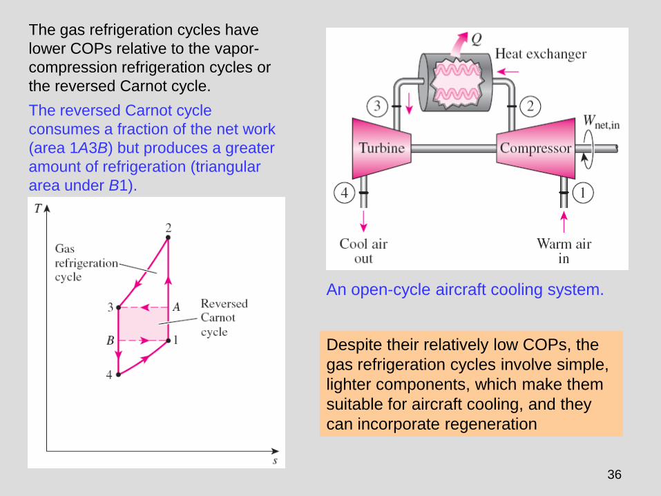
36
An open-cycle aircraft cooling system.
The gas refrigeration cycles have
lower COPs relative to the vapor-
compression refrigeration cycles or
the reversed Carnot cycle.
The reversed Carnot cycle
consumes a fraction of the net work
(area 1A3B) but produces a greater
amount of refrigeration (triangular
area under B1).
Despite their relatively low COPs, the
gas refrigeration cycles involve simple,
lighter components, which make them
suitable for aircraft cooling, and they
can incorporate regeneration

37
Without regeneration, the lowest turbine inlet temperature is T0, the
temperature of the surroundings or any other cooling medium.
With regeneration, the high-pressure gas is further cooled to T4 before
expanding in the turbine.
Lowering the turbine inlet temperature automatically lowers the turbine
exit temperature, which is the minimum temperature in the cycle.
Gas refrigeration cycle with regeneration.
Extremely low temperatures can be achieved
by repeating regeneration process.

38
ABSORPTION REFRIGERATION SYSTEMS
Ammonia absorption refrigeration cycle.
Absorption
refrigeration is
economic when there
is a source of
inexpensive thermal
energy at a
temperature of 100
to 200°C.
Some examples
include geothermal
energy, solar energy,
and waste heat from
cogeneration or
process steam
plants, and even
natural gas when it is
at a relatively low
price.

39
• Absorption refrigeration systems (ARS) involve the absorption of a
refrigerant by a transport medium.
• The most widely used system is the ammonia–water system, where
ammonia (NH3) serves as the refrigerant and water (H2O) as the transport
medium.
• Other systems include water–lithium bromide and water–lithium chloride
systems, where water serves as the refrigerant. These systems are limited
to applications such as A-C where the minimum temperature is above the
freezing point of water.
• Compared with vapor-compression systems, ARS have one major
advantage: A liquid is compressed instead of a vapor and as a result the
work input is very small (on the order of one percent of the heat supplied to
the generator) and often neglected in the cycle analysis.
• ARS are often classified as heat-driven systems.
• ARS are much more expensive than the vapor-compression refrigeration
systems. They are more complex and occupy more space, they are much
less efficient thus requiring much larger cooling towers to reject the waste
heat, and they are more difficult to service since they are less common.
• Therefore, ARS should be considered only when the unit cost of thermal
energy is low and is projected to remain low relative to electricity.
• ARS are primarily used in large commercial and industrial installations.

40
Determining the
maximum COP of
an absorption
refrigeration system.
The COP of actual absorption
refrigeration systems is usually less
than 1.
Air-conditioning systems based on
absorption refrigeration, called
absorption chillers, perform best
when the heat source can supply
heat at a high temperature with little
temperature drop.

41
Example 1: A refrigerator uses refrigerant-134a as the working fluid and operates on an
ideal vapor-compression refrigeration cycle between 0.14 and 0.8 MPa. If the mass flow
rate of the refrigerant is 0.05 kg/s, determine (a) the rate of heat removal from the
refrigerated space and the power input to the compressor, (b) the rate of heat rejection
to the environment, and (c) the COP of the refrigerator.

42

43
Example 2: Refrigerant-134a enters the compressor of a refrigerator as superheated
vapor at 0.14 MPa and -10°C at a rate of 0.05 kg/s and leaves at 0.8 MPa and 50°C.
The refrigerant is cooled in the condenser to 26°C and 0.72 MPa and is throttled to 0.15
MPa. Disregarding any heat transfer and pressure drops in the connecting lines between
the components, determine (a) the rate of heat removal from the refrigerated space and
the power input to the compressor, (b) the isentropic efficiency of the compressor, and
(c) the coefficient of performance of the refrigerator.

44

45
Example 3: Consider a two-stage cascade refrigeration system operating between the
pressure limits of 0.8 and 0.14 MPa. Each stage operates on an ideal vapor-
compression refrigeration cycle with refrigerant-134a as the working fluid. Heat rejection
from the lower cycle to the upper cycle takes place in an adiabatic counter-flow heat
exchanger where both streams enter at about 0.32 MPa. (In practice, the working fluid of
the lower cycle is at a higher pressure and temperature in the heat exchanger for
effective heat transfer.) If the mass flow rate of the refrigerant through the upper cycle is
0.05 kg/s, determine (a) the mass flow rate of the refrigerant through the lower cycle, (b)
the rate of heat removal from the refrigerated space and the power input to the
compressor, and (c) the coefficient of performance of this cascade refrigerator.

46

47
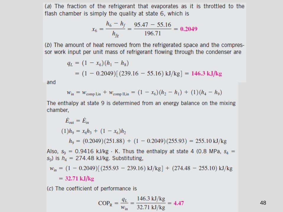
Example 4: Consider a two-stage compression refrigeration system operating between
the pressure limits of 0.8 and 0.14 MPa. The working fluid is refrigerant-134a. The
refrigerant leaves the condenser as a saturated liquid and is throttled to a flash chamber
operating at 0.32 MPa. Part of the refrigerant evaporates during this flashing process,
and this vapor is mixed with the refrigerant leaving the low-pressure compressor. The
mixture is then compressed to the condenser pressure by the high-pressure
compressor. The liquid in the flash chamber is throttled to the evaporator pressure and
cools the refrigerated space as it vaporizes in the evaporator. Assuming the refrigerant
leaves the evaporator as a saturated vapor and both compressors are isentropic,
determine (a) the fraction of the refrigerant that evaporates as it is throttled to the flash
chamber, (b) the amount of heat removed from the refrigerated space and the
compressor work per unit mass of refrigerant flowing through the condenser, and (c) the
coefficient of performance.
48

49
Example 5: An ideal gas refrigeration cycle using air as the working medium is to
maintain a refrigerated space at 0°F while rejecting heat to the surrounding medium at
80°F. The pressure ratio of the compressor is 4. Determine (a) the maximum and
minimum temperatures in the cycle, (b) the coefficient of performance, and (c) the rate of
refrigeration for a mass flow rate of 0.1 lbm/s.

50


