34
UL CLASSIFIED DAMPERS
MULTI-BLADE FIRE DAMPER - BFD SERIES
R21930
INSTALLATION / STEEL MULLIONS
MULTI-BLADE UL CLASSIFIED DYNAMIC FIRE DAMPERMODEL BFD (3 HR) / MODEL BEFD (1½ HR)
The mullions are used / necessary whenever the fire damper is installed into and opening that is larger than the largest UL rated size for the damper. The damper fire rated 1-1/2 hours.
INSTALLATION
The END CAPS are attached to wall opening by means of 25mm long and 9mm Dia steel expansion anchor embedded with M6 list headed screws.
The mullions are for using concrete block or poured walls only. The thickness of the wall is min, 177mm and max, 300mm.
Vertical, horizontal or vertical and horizontal mullions can be used depending on the area at the opening. The opening must not exceed 120” (inch) height, but it can be any width provided a vertical support mullion is used a maximum of every 120” (inch).
The mullions must be kept out of the air stream. For ducted system each subdivided opening (e.g. A x B) must be ducted individually.
If a steel inlet are used then make welding 2 x 25mm long weld per length / each side of the mullions (eg. Before installing the End Caps make sure that they are inserted in the ends of the mullions.
NOTES: (a) After installations of steel mullions refer installation page of the fire damper which is provided by the manufacturer.
MANUFACTURING AND FIELD INSTALLATION INSTRUCTIONS FOR STEEL MULLIONS (as per SMACNA):
(b) Do not fastened retaining angle to the wall or steel mullions. The steel mullions must be free to float.
35
UL CLASSIFIED DAMPERS
COMBINED FIRE/SMOKE DAMPER - BMFSD SERIES
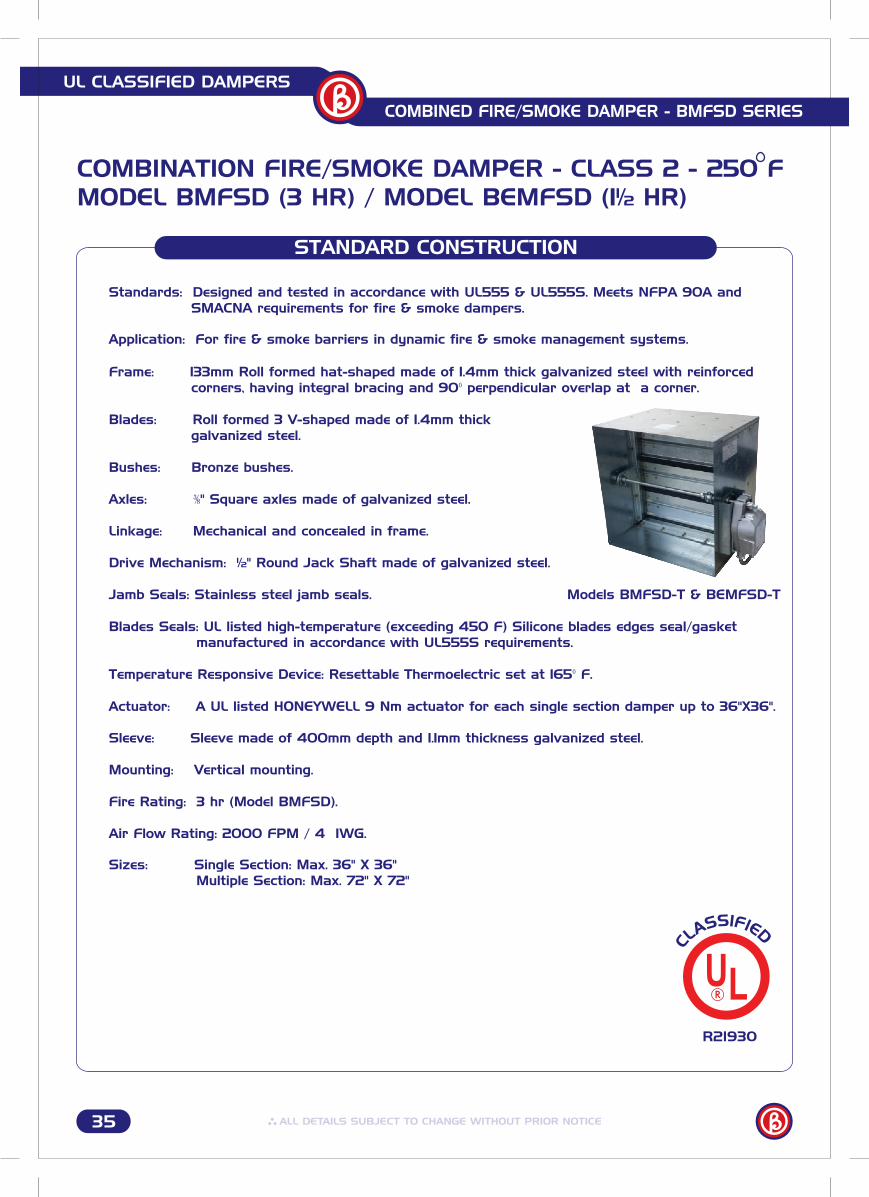
Mounting: Vertical mounting.
Temperature Responsive Device: Resettable Thermoelectric set at 165 F.
Linkage: Mechanical and concealed in frame.
Axles: " Square axles made of galvanized steel.
Bushes: Bronze bushes.
galvanized steel.Blades: Roll formed 3 V-shaped made of 1.4mm thick
corners, having integral bracing and 90 perpendicular overlap at a corner.Frame: 133mm Roll formed hat-shaped made of 1.4mm thick galvanized steel with reinforced
SMACNA requirements for fire & smoke dampers.Standards: Designed and tested in accordance with UL555 & UL555S. Meets NFPA 90A and
OPTIONS
R21930
Actuator: A UL listed HONEYWELL 9 Nm actuator for each single section damper up to 36"X36".
Sizes: Single Section: Max. 36" X 36" Multiple Section: Max. 72" X 72"
Fire Rating: 3 hr (Model BMFSD).
COMBINATION FIRE/SMOKE DAMPER - CLASS 2 - 250 FMODEL BMFSD (3 HR) / MODEL BEMFSD (1½ HR)
STANDARD CONSTRUCTION
Application: For fire & smoke barriers in dynamic fire & smoke management systems.
Drive Mechanism: ½" Round Jack Shaft made of galvanized steel. Jamb Seals: Stainless steel jamb seals. Models BMFSD-T & BEMFSD-T
Blades Seals: UL listed high-temperature (exceeding 450 F) Silicone blades edges seal/gasket manufactured in accordance with UL555S requirements.
Sleeve: Sleeve made of 400mm depth and 1.1mm thickness galvanized steel.
Air Flow Rating: 2000 FPM / 4 IWG.
36
UL CLASSIFIED DAMPERS
COMBINED FIRE/SMOKE DAMPER - BMFSD SERIES
OPTIONS
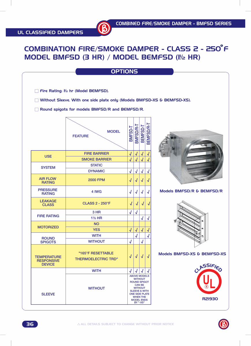
Without Sleeve. With one side plate only (Models BMFSD-XS & BEMFSD-XS).
Fire Rating: 1½ hr (Model BEMFSD).
Round spigots for models BMFSD/R and BEMFSD/R.
R21930
COMBINATION FIRE/SMOKE DAMPER - CLASS 2 - 250 FMODEL BMFSD (3 HR) / MODEL BEMFSD (1½ HR)
Models BMFSD/R & BEMFSD/R
Models BMFSD-XS & BEMFSD-XS
FIRE BARRIER
SMOKE BARRIER
STATIC
DYNAMIC
2000 FPM
4 IWG
CLASS 2 - 250°F
3 HR
1½ HR
NO
YES
WITH
WITHOUT
"165°F RESETTABLE
THERMOELECTRIC TRD"
WITH
WITHOUT
√
√
√
√
√
√
√
√
√
√
√
√
√
√
√
√
√
√
√
√
√
√
√
√
√
√
√
√
√
√
√
√
√
√
√
√
√
√
√
√
√
√
√
√
BMFS
D-T
BMFS
D/R-
TBE
MFS
D-T
BEM
FSD/
R-T
USE
SYSTEM
AIR FLOW RATING
PRESSURE RATING
LEAKAGECLASS
FIRE RATING
MOTORIZED
ROUNDSPIGOTS
TEMPERATURERESPONSIVE
DEVICE
SLEEVE
FEATUREMODEL
ABOVE MODELS WITHOUT
ROUND SPIGOT CAN BE
WITHOUT SLEEVE & WITH ONE SIDE PLATE
WHEN THE MODEL ENDS
BY "-XS"
37
UL CLASSIFIED DAMPERS
COMBINED FIRE/SMOKE DAMPER - BMFSD SERIES
ASSEMBLY
COMBINATION FIRE/SMOKE DAMPER - CLASS 2 - 250 FMODEL BMFSD (3 HR) / MODEL BEMFSD (1½ HR)
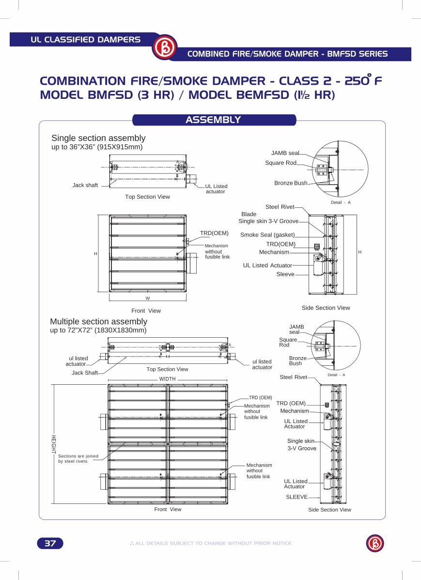
Actuator
Sleeve
Side Section View
Single skin 3-V Groove
JAMB seal
Square Rod
Bronze Bush
Detail - ASteel Rivet
UL Listed
H
Smoke Seal (gasket)
Blade
MechanismTRD(OEM)
Top Section View
A
actuatorUL ListedJack shaft
Front View
W
H
Mechanismwithout fusible link
TRD(OEM)
Single section assemblyup to 36”X36” (915X915mm)
Multiple section assemblyup to 72”X72” (1830X1830mm)
Top Section View
Front View
actuatorul listed
Jack Shaft
A
Sections are joinedby steel rivets
HE
IGH
T
WIDTH
actuatorul listed
Mechanismwithout fusible link
Mechanismwithout fusible link
TRD (OEM)
SLEEVE
Side Section View
Steel Rivet
UL Listed Actuator
UL Listed Actuator
JAMBseal
SquareRod
Bronze Bush
Detail - A
TRD (OEM)
36
UL CLASSIFIED DAMPERS
COMBINED FIRE/SMOKE DAMPER - BMFSD SERIES
OPTIONS
Without Sleeve. With one side plate only (Models BMFSD-XS & BEMFSD-XS).
Fire Rating: 1½ hr (Model BEMFSD).
Round spigots for models BMFSD/R and BEMFSD/R.
R21930
COMBINATION FIRE/SMOKE DAMPER - CLASS 2 - 250 FMODEL BMFSD (3 HR) / MODEL BEMFSD (1½ HR)
Models BMFSD/R & BEMFSD/R
Models BMFSD-XS & BEMFSD-XS
FIRE BARRIER
SMOKE BARRIER
STATIC
DYNAMIC
2000 FPM
4 IWG
CLASS 2 - 250°F
3 HR
1½ HR
NO
YES
WITH
WITHOUT
"165°F RESETTABLE
THERMOELECTRIC TRD"
WITH
WITHOUT
√
√
√
√
√
√
√
√
√
√
√
√
√
√
√
√
√
√
√
√
√
√
√
√
√
√
√
√
√
√
√
√
√
√
√
√
√
√
√
√
√
√
√
√
BMFS
D-T
BMFS
D/R-
TBE
MFS
D-T
BEM
FSD/
R-T
USE
SYSTEM
AIR FLOW RATING
PRESSURE RATING
LEAKAGECLASS
FIRE RATING
MOTORIZED
ROUNDSPIGOTS
TEMPERATURERESPONSIVE
DEVICE
SLEEVE
FEATUREMODEL
ABOVE MODELS WITHOUT
ROUND SPIGOT CAN BE
WITHOUT SLEEVE & WITH ONE SIDE PLATE
WHEN THE MODEL ENDS
BY "-XS"
37
UL CLASSIFIED DAMPERS
COMBINED FIRE/SMOKE DAMPER - BMFSD SERIES
ASSEMBLY
COMBINATION FIRE/SMOKE DAMPER - CLASS 2 - 250 FMODEL BMFSD (3 HR) / MODEL BEMFSD (1½ HR)
Actuator
Sleeve
Side Section View
Single skin 3-V Groove
JAMB seal
Square Rod
Bronze Bush
Detail - ASteel Rivet
UL Listed
H
Smoke Seal (gasket)
Blade
MechanismTRD(OEM)
Top Section View
A
actuatorUL ListedJack shaft
Front View
W
H
Mechanismwithout fusible link
TRD(OEM)
Single section assemblyup to 36”X36” (915X915mm)
Multiple section assemblyup to 72”X72” (1830X1830mm)
Top Section View
Front View
actuatorul listed
Jack Shaft
A
Sections are joinedby steel rivets
HE
IGH
T
WIDTH
actuatorul listed
Mechanismwithout fusible link
Mechanismwithout fusible link
TRD (OEM)
SLEEVE
Side Section View
Steel Rivet
UL Listed Actuator
UL Listed Actuator
JAMBseal
SquareRod
Bronze Bush
Detail - A
TRD (OEM)
38
UL CLASSIFIED DAMPERS
COMBINED FIRE/SMOKE DAMPER - BMFSD SERIES
PERFORMANCE DATA
COMBINATION FIRE/SMOKE DAMPER - CLASS 2 - 250 FMODEL BMFSD (3 HR) / MODEL BEMFSD (1½ HR)
ORDERING KEY R21930
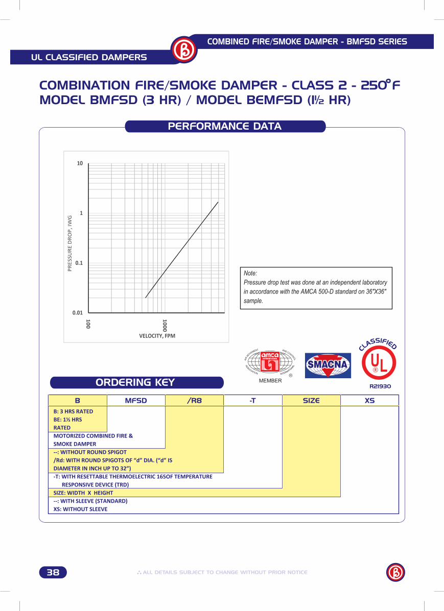
B MFSD /R8 -T SIZE XS
B: 3 HRS RATEDBE: 1½ HRSRATEDMOTORIZED COMBINED FIRE & SMOKE DAMPER--: WITHOUT ROUND SPIGOT/Rd: WITH ROUND SPIGOTS OF “d” DIA. (“d” ISDIAMETER IN INCH UP TO 32”)-T: WITH RESETTABLE THERMOELECTRIC 165OF TEMPERATURE RESPONSIVE DEVICE (TRD)SIZE: WIDTH X HEIGHT--: WITH SLEEVE (STANDARD)XS: WITHOUT SLEEVE
39
UL CLASSIFIED DAMPERS
COMBINED FIRE/SMOKE DAMPER - BMFSD SERIES
R21930
INSTALLATION
COMBINATION FIRE/SMOKE DAMPER - CLASS 2 - 250 FMODEL BMFSD (3 HR) / MODEL BEMFSD (1½ HR)
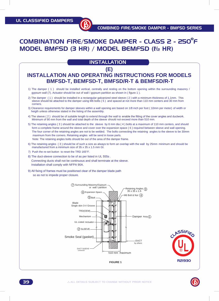
Minimum of 90 mm from the wall and total depth of the sleeve
7) Push the re-set button to reset the TRD 165°F.
Note: The retaining angles bolts should be out of the area of the damper frame.
should not exceed more than 510 mm.
8) The duct-sleeve connection to be of as per listed in UL 555s .
9) All fixing of frames must be positioned clear of the damper blade path
Connecting ducts shall not be continuous and shall terminate at the sleeve.Installation shall comply with NFPA 90A.
so as not to impede proper closure.
by others
DUCT SLEEVEconnection
Damper Assy
510 mm maximum
Retaining Angles
M6 Bolt & Nut
Surrounding Masonry/Gypsum
Expansion Space 35 x 35 x 1.5
2
3
46
SLEEVE
Single skin 3-V Groove
Bolt
Blade
Mechanism
UL Listed Actuator
5
or wall / partition
DUCT
TRD(OEM)
1
7
Smoke Seal (gasket)
1) The damper ( 1 ) should be installed vertical, centrally and resting on the bottom opening within the surrounding masonry / gypsum wall (7). Actuator should be out of wall / gypsum partition as shown in ( figure 1 ).
2) The damper ( 1 ) should be installed in a rectangular galvanized steel sleeve ( 2 ) with a minimum thickness of 1.1mm. This sleeve should be attached to the damper using M6 bolts ( 5 ) and spaced at not more than 110 mm centers and 30 mm from corners.
3) Clearance requirements for damper sleeves within a wall opening are based on 1/8 inch per foot ( 10mm per meter) of width or heigth unless otherwise stated in the listing of the assembly.
4) The sleeve ( 2 ) should be of suitable length to extend through the wall to enable the fitting of the cover angles and ductwork.
5) The retaining angles ( 3 ) should be attached to the sleeve by 6 mm dia ( 4 ) bolts at a maximum of 110 mm centers, and should form a complete frame around the sleeve and cover over the expansion space ( 6 ) required between sleeve and wall opening. The four corner of the retaining angles are not to be welded. The bolts connecting the retaining angles to the sleeve to be 30mm maximum from the corners. Retaining angles will be send in loose parts.
6) The retaining angles ( 3 ) should be of such a size as always to form an overlap with the wall by 25mm minimum and should be manufactured from a minimum size of 35 x 35 x 1.5 mm Gl.
(E) INSTALLATION AND OPERATING INSTRUCTIONS FOR MODELS
BMFSD-T, BEMFSD-T, BMFSD/R-T & BEMFSD/R-T
FIGURE 1
38
UL CLASSIFIED DAMPERS
COMBINED FIRE/SMOKE DAMPER - BMFSD SERIES
PERFORMANCE DATA
COMBINATION FIRE/SMOKE DAMPER - CLASS 2 - 250 FMODEL BMFSD (3 HR) / MODEL BEMFSD (1½ HR)
ORDERING KEY R21930
B MFSD /R8 -T SIZE XS
B: 3 HRS RATEDBE: 1½ HRSRATEDMOTORIZED COMBINED FIRE & SMOKE DAMPER--: WITHOUT ROUND SPIGOT/Rd: WITH ROUND SPIGOTS OF “d” DIA. (“d” ISDIAMETER IN INCH UP TO 32”)-T: WITH RESETTABLE THERMOELECTRIC 165OF TEMPERATURE RESPONSIVE DEVICE (TRD)SIZE: WIDTH X HEIGHT--: WITH SLEEVE (STANDARD)XS: WITHOUT SLEEVE
39
UL CLASSIFIED DAMPERS
COMBINED FIRE/SMOKE DAMPER - BMFSD SERIES
R21930
INSTALLATION
COMBINATION FIRE/SMOKE DAMPER - CLASS 2 - 250 FMODEL BMFSD (3 HR) / MODEL BEMFSD (1½ HR)
Minimum of 90 mm from the wall and total depth of the sleeve
7) Push the re-set button to reset the TRD 165°F.
Note: The retaining angles bolts should be out of the area of the damper frame.
should not exceed more than 510 mm.
8) The duct-sleeve connection to be of as per listed in UL 555s .
9) All fixing of frames must be positioned clear of the damper blade path
Connecting ducts shall not be continuous and shall terminate at the sleeve.Installation shall comply with NFPA 90A.
so as not to impede proper closure.
by others
DUCT SLEEVEconnection
Damper Assy
510 mm maximum
Retaining Angles
M6 Bolt & Nut
Surrounding Masonry/Gypsum
Expansion Space 35 x 35 x 1.5
2
3
46
SLEEVE
Single skin 3-V Groove
Bolt
Blade
Mechanism
UL Listed Actuator
5
or wall / partition
DUCT
TRD(OEM)
1
7
Smoke Seal (gasket)
1) The damper ( 1 ) should be installed vertical, centrally and resting on the bottom opening within the surrounding masonry / gypsum wall (7). Actuator should be out of wall / gypsum partition as shown in ( figure 1 ).
2) The damper ( 1 ) should be installed in a rectangular galvanized steel sleeve ( 2 ) with a minimum thickness of 1.1mm. This sleeve should be attached to the damper using M6 bolts ( 5 ) and spaced at not more than 110 mm centers and 30 mm from corners.
3) Clearance requirements for damper sleeves within a wall opening are based on 1/8 inch per foot ( 10mm per meter) of width or heigth unless otherwise stated in the listing of the assembly.
4) The sleeve ( 2 ) should be of suitable length to extend through the wall to enable the fitting of the cover angles and ductwork.
5) The retaining angles ( 3 ) should be attached to the sleeve by 6 mm dia ( 4 ) bolts at a maximum of 110 mm centers, and should form a complete frame around the sleeve and cover over the expansion space ( 6 ) required between sleeve and wall opening. The four corner of the retaining angles are not to be welded. The bolts connecting the retaining angles to the sleeve to be 30mm maximum from the corners. Retaining angles will be send in loose parts.
6) The retaining angles ( 3 ) should be of such a size as always to form an overlap with the wall by 25mm minimum and should be manufactured from a minimum size of 35 x 35 x 1.5 mm Gl.
(E) INSTALLATION AND OPERATING INSTRUCTIONS FOR MODELS
BMFSD-T, BEMFSD-T, BMFSD/R-T & BEMFSD/R-T
FIGURE 1
40
UL CLASSIFIED DAMPERS
COMBINED FIRE/SMOKE DAMPER - BMFSD SERIES
R21930
INSTALLATION
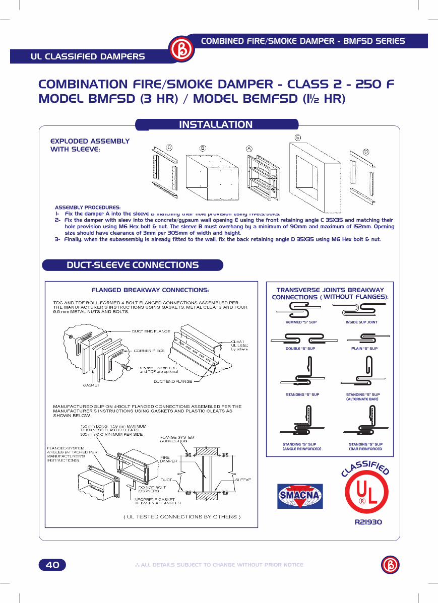
ASSEMBLY PROCEDURES:1- Fix the damper A into the sleeve B matching their hole provision using rivets/bolts.2- Fix the damper with sleev into the concrete/gypsum wall opening E using the front retaining angle C 35X35 and matching their hole provision using M6 Hex bolt & nut. The sleeve B must overhang by a minimum of 90mm and maximum of 152mm. Opening size should have clearance of 3mm per 305mm of width and height.3- Finally, when the subassembly is already fitted to the wall, fix the back retaining angle D 35X35 using M6 Hex bolt & nut.
EXPLODED ASSEMBLY WITH SLEEVE:
DUCT-SLEEVE CONNECTIONS
STANDING “S” SUP STANDING “S” SLIP(ALTERNATE BAR)
STANDING “S” SLIP(ANGLE REINFORCED)
STANDING “S” SLIP(BAR REINFORCED
DOUBLE “S” SUP PLAIN “S” SLIP
HEMMED “S” SUP INSIDE SUP JOINT
FLANGED BREAKWAY CONNECTIONS: TRANSVERSE JOINTS BREAKWAY CONNECTIONS ( WITHOUT FLANGES):
COMBINATION FIRE/SMOKE DAMPER - CLASS 2 - 250 FMODEL BMFSD (3 HR) / MODEL BEMFSD (1½ HR)
41
UL CLASSIFIED DAMPERS
SMOKE DAMPER - BMSD SERIES
Linkage: Mechanical and concealed in frame.
Axles: " Square axles made of galvanized steel.
Bushes: Bronze bushes.
galvanized steel.Blades: Roll formed 3 V-shaped made of 1.4mm thick
corners, having integral bracing and 90 perpendicular overlap at a corner.Frame: 133mm Roll formed hat-shaped made of 1.4mm thick galvanized steel with reinforced
OPTIONS
R21930
Actuator: A UL listed HONEYWELL 9 Nm actuator for each single section damper up to 36"X36".
Sizes: Single Section: Max. 36" X 36" Multiple Section: Max. 72" X 72"
STANDARD CONSTRUCTION
SMOKE DAMPER - CLASS 2 - 250 FMODEL BMSD
Standards: Designed and tested in accordance with UL555S. Meets NFPA 90A and SMACNA requirements for fire & smoke dampers.
Application: For dynamic smoke management systems.
Mounting: Vertical/Horizontal mounting.
Drive Mechanism: ½" Round Jack Shaft made of galvanized steel. Jamb Seals: Stainless steel jamb seals. Model BMSD
Blades Seals: UL listed high-temperature (exceeding 450 F) Silicone blades edges seal/gasket manufactured in accordance with UL555S requirements.
Air Flow Rating: 2000 FPM / 4 IWG.
Sleeve: Sleeve made of 400mm depth and 1.1mm thickness galvanized steel.


