Computer Networks DCLAB-ghcho 2000 Fall
1
Course Syllabus (I) Lecturer : Gihwan Cho
office : room 607 (voice 3437) [email protected]
This material is based on: Andrew S. Tannenbaum, Computer Networks, Third Edition,
Prentice Hall, ISBN 0-13-349945-6 D. Comer, Internetworking with TCP/IP, Third Edition, Prenti
ce Hall, ISBN 0-13-227836-7 Course objectives
understanding of the basic principles of computer networks, Internet and its protocols
understanding in detail of the main subjects of computer networks, Internet and its protocols
Computer Networks DCLAB-ghcho 2000 Fall
2
Courses Syllabus (II) Course outline
lecturer will present the basic principles of computer networks, Internet and its protocols
the lecture will suggest some of main subjects in computer network (some of these may be proposed by yourself)
then, you are planed to choose an identified subject, and work elaborately for it, and finally be taken a presentation for the identified subject
Expected works 1 presentation for 1 subject 2 examinations (mid, final)
Lecture information cs.chonbuk.ac.kr/~ghcho/courses/netsem.html
Computer Networks DCLAB-ghcho 2000 Fall
3
Courses Syllabus (III) Policy on the presentation
is given I hour presentation time per person is recommended to use about 30 slides in ppt format is checked mainly how much you are understand for the sele
cted subject the presentation material should be send to lecture at least 1
2 hour before you take it (if not, …) if you can not have a presentation at an arranged time, you
must consult with the other to exchange the time, and inform me at least 24 hour before the arranged time (if not, …)
for the poor presentation (mainly, in the understanding viewpoint), another chance would be given
the presentation will be tested with two examinations Grading
presentation 40 : material 10, understanding 20, Q/A 10 exam. 60 : mid. 30, final 30
Computer Networks DCLAB-ghcho 2000 Fall
4
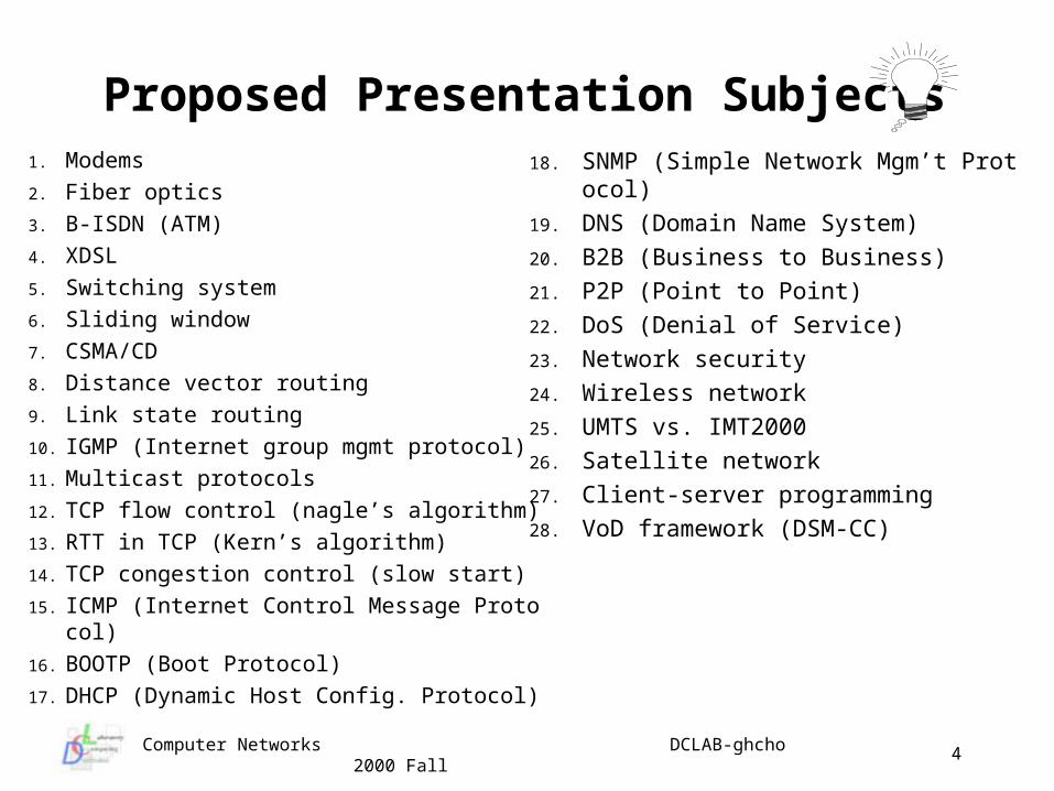
Proposed Presentation Subjects1. Modems
2. Fiber optics
3. B-ISDN (ATM)
4. XDSL
5. Switching system
6. Sliding window
7. CSMA/CD
8. Distance vector routing
9. Link state routing
10. IGMP (Internet group mgmt protocol)
11. Multicast protocols
12. TCP flow control (nagle’s algorithm)
13. RTT in TCP (Kern’s algorithm)
14. TCP congestion control (slow start)
15. ICMP (Internet Control Message Protocol)
16. BOOTP (Boot Protocol)
17. DHCP (Dynamic Host Config. Protocol)
18. SNMP (Simple Network Mgm’t Protocol)
19. DNS (Domain Name System)
20. B2B (Business to Business)
21. P2P (Point to Point)
22. DoS (Denial of Service)
23. Network security
24. Wireless network
25. UMTS vs. IMT2000
26. Satellite network
27. Client-server programming
28. VoD framework (DSM-CC)
Computer Networks DCLAB-ghcho 2000 Fall
5
Lecture Topic 1
Overall Introduction of
Computer Networks
What good is a computer network Network technologies Network software ISO/OSI 7 layer model TCP/IP model Network standardization
Computer Networks DCLAB-ghcho 2000 Fall
6
Introduction (I) Old model was the Mainframe based computer center
current model of computing environment is an interconnected collection of autonomous computers
We call such a system a Computer Network (CN) a computer network is a set of nodes that are interconnected to
permit the exchange of information An CN is necessary for a Distributed System but is not the same
in a distributed system, the existence of multiple autonomous systems is transparent
What good is a CN economic and technical Issues: resource sharing; reliability;
cost savings (client/server); scalability; communications (email) consumer issues: telecommuting; interactive entertainment and
video on demand; socio-political interaction; selling stuff yucky issues: hate speech; snooping/employee monitoring;
misinformation; ownership & copyright; theft & hacking
Computer Networks DCLAB-ghcho 2000 Fall
7
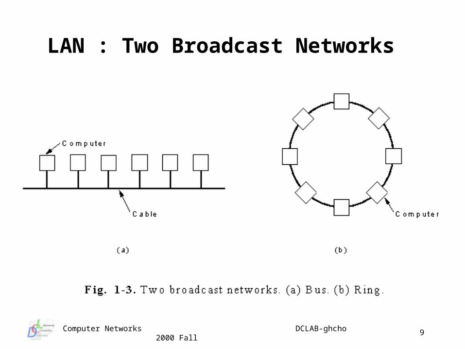
Network Technology A network is a carrier of information between 2 or more entities Generally two types of transmission technology: broadcast
single channel is shared by all the machines on the network messages sent by one node are received by all use special address field in message to specify target of
comm.(broadcast/multicast) usually small (geographically) networks
point-to-point connections between individual pairs of machines message may pass through many pairs of point-to-point
connections to get from source to destination often machines may have multiple point-to-point connections large (geographically) networks..
Computer Networks DCLAB-ghcho 2000 Fall
8
Classes of Networks : LAN LAN (Local Area Network)
maximum distance not more than a few kms ownership by a single organization transmission speed of at least several Mbps (tens to hundre
ds are economical) often broadcast, shared media based some widely used standards include:
IEEE 802.3 - Ethernet IEEE 803.5 - Token ring FDDI ATM
an important issue in broadcast LANs is the allocation of the shared channel (media access control)
control may be static (time division multiplexing) or dynamic (contention or arbitration)
Computer Networks DCLAB-ghcho 2000 Fall
9
LAN : Two Broadcast Networks
Computer Networks DCLAB-ghcho 2000 Fall
10
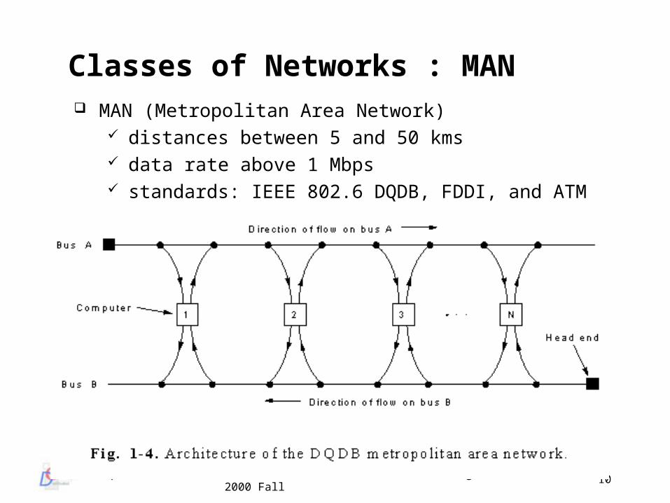
Classes of Networks : MAN MAN (Metropolitan Area Network)
distances between 5 and 50 kms data rate above 1 Mbps standards: IEEE 802.6 DQDB, FDDI, and ATM
Computer Networks DCLAB-ghcho 2000 Fall
11
Classes of Networks : WAN WAN (Wide Area Network)
spans entire states or countries data rate of 1.544, and 45 Mbps common higher data rates are available with the wide deployment of
ATM backbone networks often owned by multiple organizations usually separate communications functions from application
functions transmission lines: circuits, channels or trunks switching elements : Intermediate Systems, Packet
Switching Node, Data Switching Exchange, Router, etc. Intermediate systems store a complete packet before
forwarding it : store-and-forward; packet switched; point-to-point network
Computer Networks DCLAB-ghcho 2000 Fall
12
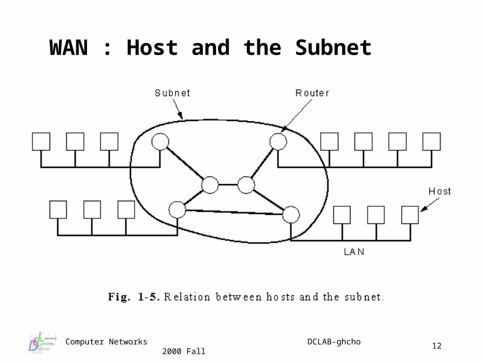
WAN : Host and the Subnet
Computer Networks DCLAB-ghcho 2000 Fall
13
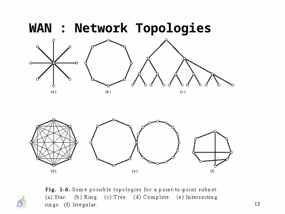
WAN : Network Topologies
Computer Networks DCLAB-ghcho 2000 Fall
14
Classes of Networks : Wireless Networks Wireless Network
wireless comm. has been used from 1901, by G. Marconi, but its technology did not known, why?
channel multiplexing : AMPS, TDMA, CDMA two up-coming information technologies invent a new compu
ting paradigm, so mobile computing mobile hosts : PDA, palm-top, notebook mobile packet data : IMT 2000, UMTS, GPRS
permit user to access information anytime, anywhere one-line mobility vs. off-line mobility must provide seamless connectivity actually it would be based a fixed network, possibly Internet,
to be a general information network why wireless ? - timely news, and way too much of it
- information where people want to be
Computer Networks DCLAB-ghcho 2000 Fall
15
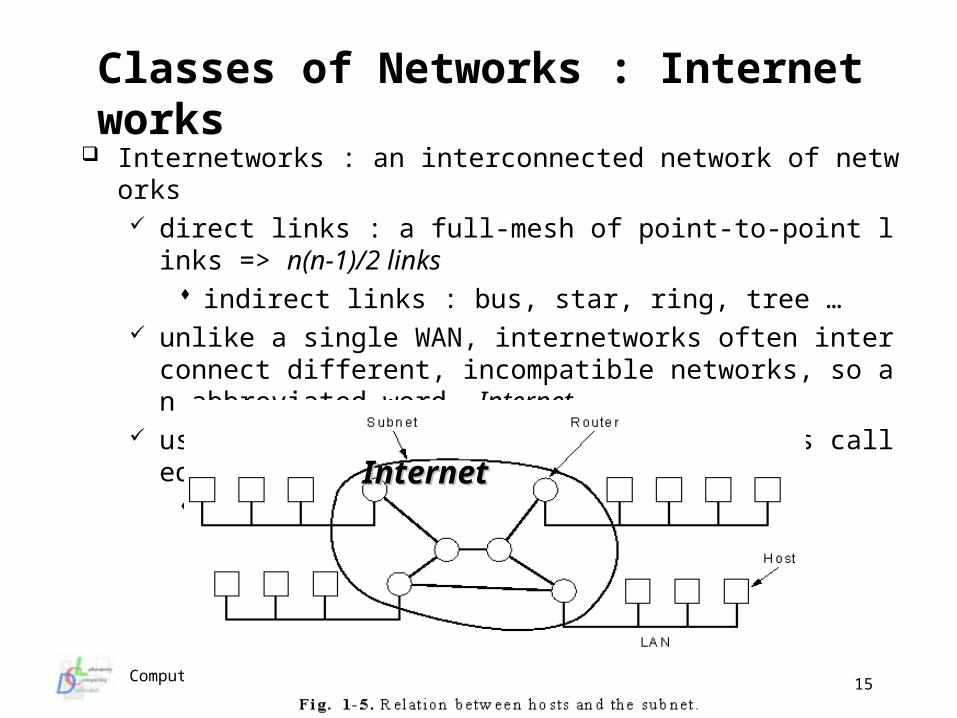
Classes of Networks : Internetworks Internetworks : an interconnected network of networks
direct links : a full-mesh of point-to-point links => n(n-1)/2 links indirect links : bus, star, ring, tree …
unlike a single WAN, internetworks often interconnect different, incompatible networks, so an abbreviated word, Internet
use special types of intermediate systems called Gateways cf) repeater, bridge, router, gateway
InternetInternet
Computer Networks DCLAB-ghcho 2000 Fall
16
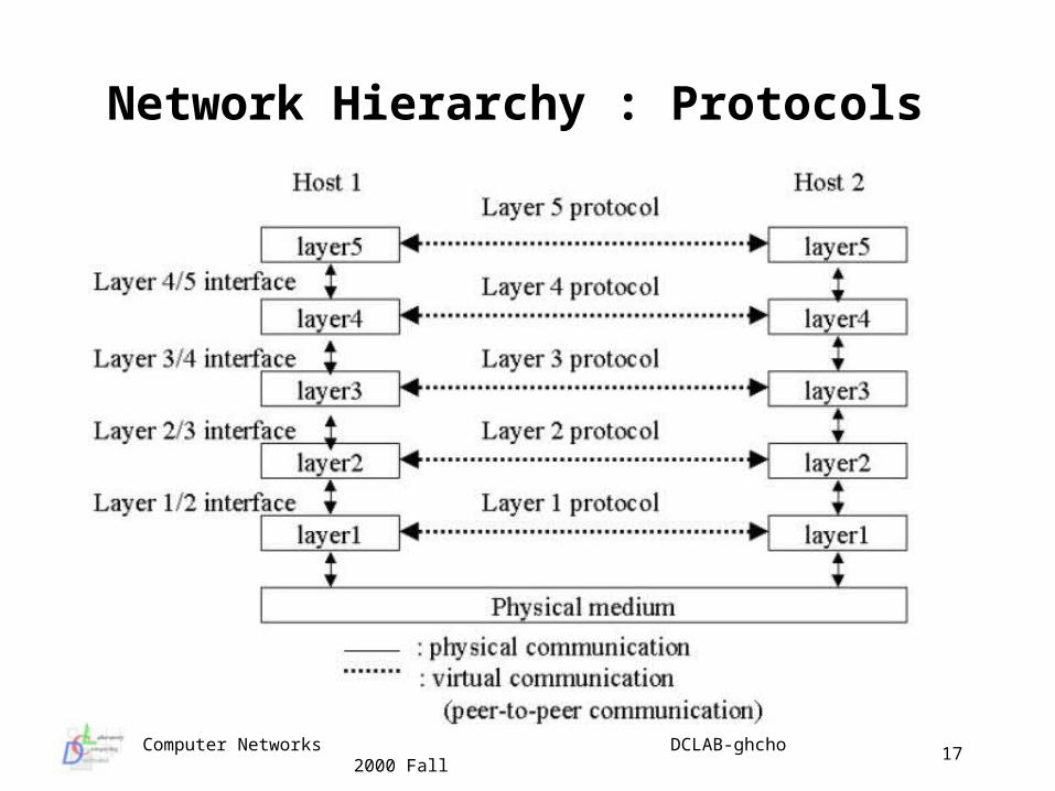
Network Software Network software is highly structured This technique has been immensely successful The key is Layered design
each layer provides a service to the layer above each layer hides details of how the service is provided to the
layer above the Nth layer on one machine talks to or interacts with the Nth
layer on another machine Conventions and rules governing this interaction are specified
by the Layer N Protocol a protocol is an agreement about how communications are
to proceed, without a protocol, communication can be difficult or even impossible
e.g. telephone conversation, postal addresses
Computer Networks DCLAB-ghcho 2000 Fall
17
Network Hierarchy : Protocols
Computer Networks DCLAB-ghcho 2000 Fall
18
Network Software : Protocols (Cont.) Information is not actually transferred directly between peer laye
r N entities peer layer N entities carry on a virtual communication using t
he services of the layers below layer N passes data and control information down to (or rece
ives data and control from) Layer N-1 until the physical medium is reached
Interfaces exist between each layer Interface defines which primitive functions and services layer N-
1 provides to layer N Want layers to:
perform a well defined, logically related set of functions minimize the amount of infor. need to pass between layers keep interfaces “clean” to allow easy and transparent replac
ement of layers
Computer Networks DCLAB-ghcho 2000 Fall
19
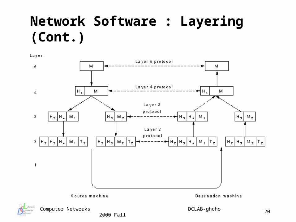
Network Software : Layering The set of protocols and layers together make up the Network
Architecture a network architecture Specification must provide enough
information to allow implementation in hardware/software implementation specific details are not part of the
architecture and should be irrelevant for inter-operation with one protocol per layer we have a Protocol Stack
Layering is used in other software, e.g. UNIX OS For network software the important difference is that we are not
allowed to violate layering (layer 5 cannot directly access layer 1)
For network software it’s important layers don’t peek into headers of other layers and rely on protocol data of other layers
Computer Networks DCLAB-ghcho 2000 Fall
20
Network Software : Layering (Cont.)
Computer Networks DCLAB-ghcho 2000 Fall
21
The Benefit of Layered Protocols The network architectures, protocols and protocol stacks are the
fundamentals of computer networks multilayer communications protocols allow:
ready adaptation of successful protocols to new technology (prevent obsolescence)
migration of protocols from software implementation (slow) to hardware (fast) as they evolve
separate data and control information support differing levels of abstraction (message, packet, fram
e) with different sizes allow segmentation of large messages peer process abstraction facilitates reduction of difficult desig
n task (a network architecture) into smaller manageable tasks (protocol layer architecture)
typically lower layer protocols of “network software” are implemented in silicon (hardware)
Computer Networks DCLAB-ghcho 2000 Fall
22
Understanding Services and Protocols The protocol is a set of rules about the format and meaning of
data units exchanged by the peer entities within a layer The service is a set of primitives (operations) that a layer
provider to the layer above it The interface tells the processes above it how to access it, that
is, it specifies what parameters are and what results to expect protocol is used by entity to implement services protocol and/or it’s implementation can change and as long
as the service (interface) remains unchanged higher layers are happy and continue to work
like in abstract data types or object orientation we decouple interface and implementation
Computer Networks DCLAB-ghcho 2000 Fall
23
Network Software : Design Issues Addressing and Routing Data transfer : simplex, half duplex, full duplex Connection management : # of logical channels per connection Error recovery : error detection, correction, retransmission Message ordering : full, partial, causal Flow control / Rate control Assembly / Disassembly Multiplexing
TDM (Time Division Multiplexing) FDM (Frequency Division Multiplexing) CDM (Code Division Multiplexing)
Computer Networks DCLAB-ghcho 2000 Fall
24
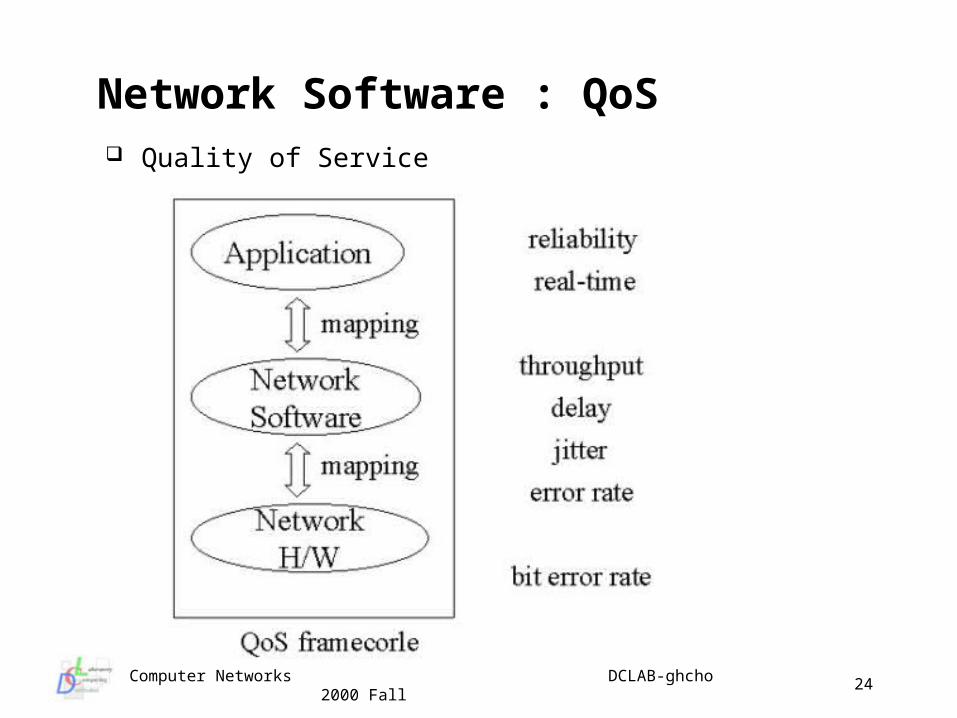
Network Software : QoS Quality of Service
Computer Networks DCLAB-ghcho 2000 Fall
25
The ISO/OSI Reference Model Developed by the International Standards Organization (ISO) to f
acilitate the intern’l standardization of communications protocols ISO basic reference model for Open Systems Interconnect (henc
e: ISO/OSI), started in the mid-1970’s the reference model itself is not a network architecture (doesn
’t specify any protocols or services) ISO also developed network architecture standards
No assumptions are made regarding: programming language bindings operating system bindings applications programming interfaces
Biggest problems very long time to complete the model and protocol standards very hard to understand the detailed standards difficult (expensive) to get the standards documents
Computer Networks DCLAB-ghcho 2000 Fall
26
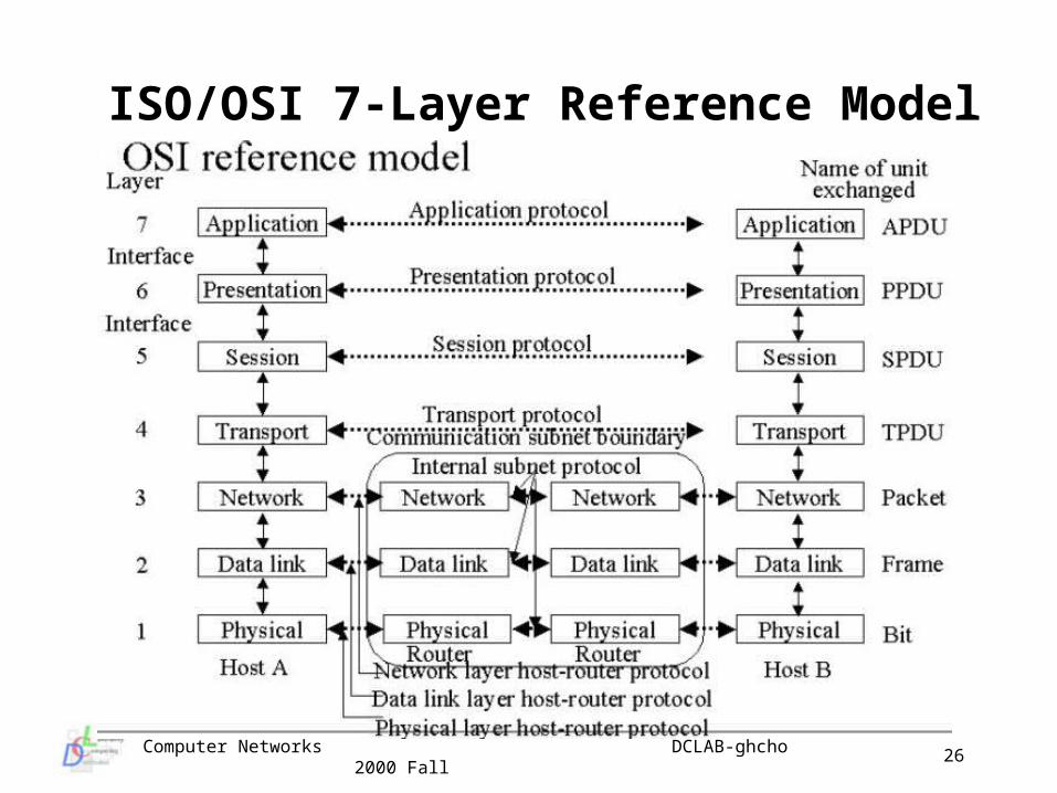
ISO/OSI 7-Layer Reference Model
Computer Networks DCLAB-ghcho 2000 Fall
27
OSI Layer 1 : Physical Layer Primary function is transmitting raw bits over a physical
communications channel Primary design issues include: mechanical, electrical, coding,
physical characteristics how many pins in the connector what voltage represents a “1” versus a “0” etc.
By “raw bits” we mean there is no interpretation of the bits - stream of bits in and bits out
Computer Networks DCLAB-ghcho 2000 Fall
28
OSI Layer 2 : Data Link Layer Primary function is to make Layer 1 into what appears to be a
channel free of undetected errors Deals with data in chunks (typically 100s-1000s of bytes)
generally called Frames This layer must create/recognize frame boundaries
remember - physical layer does not care often requires special bit patterns to signal boundaries may have to deal with possibility of pattern appearing in data
Among the key issues dealt with are: error handling (e.g. corrupted frame) flow control providing various qualities of service
For Broadcast networks a key issue is controlling access to the channel: use a sub-layer called the Media Access Control (MAC)
Computer Networks DCLAB-ghcho 2000 Fall
29
OSI Layer 3 : Network Layer Primary function is control the operation of the subnet (layers
below) Among the key issues dealt with are:
how routing packets from source to destination through the network (or multiple networks) using static or dynamic routing algorithms
controlling congestion in the subnet accounting functions (for billing) translating between protocols across heterogeneous
networks (address, packet size, …) concerned with addressing
Computer Networks DCLAB-ghcho 2000 Fall
30
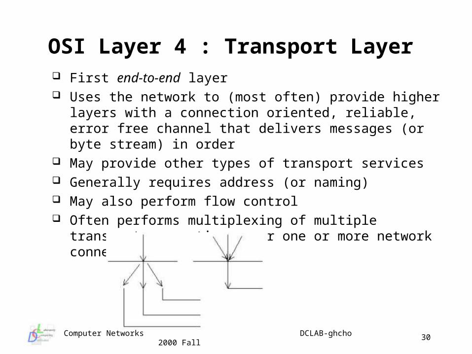
OSI Layer 4 : Transport Layer First end-to-end layer Uses the network to (most often) provide higher layers with a
connection oriented, reliable, error free channel that delivers messages (or byte stream) in order
May provide other types of transport services Generally requires address (or naming) May also perform flow control Often performs multiplexing of multiple transport connections
over one or more network connections
Computer Networks DCLAB-ghcho 2000 Fall
31
OSI Layer 5, 6 : Session, Presentation Session layer
sort of an unwanted layer, this layer is usually very thin and little more than a pass through for most protocols
manages dialog control (e.g. may manage who’s turn to talk in a high-level half-duplex protocol)
manages synchronization of transactions which may need to be able to roll back in case of a crash
Presentation layer rather than being concerned with moving information the
presentation layer is concerned with the interpretation of information representation
ensures that the syntax and meaning is the same for each participant in a communication
provides for standard representation and may provide capabilities for conversion of data
Computer Networks DCLAB-ghcho 2000 Fall
32
OSI Layer 7 : Application Layer, and The layer where end-user applications live All the rest of the layers exist to support these applications Layering exists so we can move these around to different
machines, and so they can communicate across any platforms - Open Systems Interconnect
Review: functions of the OSI layers layer 1 (physical): transmission of bits layer 2 (data link): transmission of frames on one given link layer 3 (network): routing of packets through the network layer 4 (transport): end-to-end delivery of messages layer 5 (session): end-to-end conversation, synchronization layer 6 (presentation): formatting, encryption, and
compression layer 7 (application): user applications
Computer Networks DCLAB-ghcho 2000 Fall
33
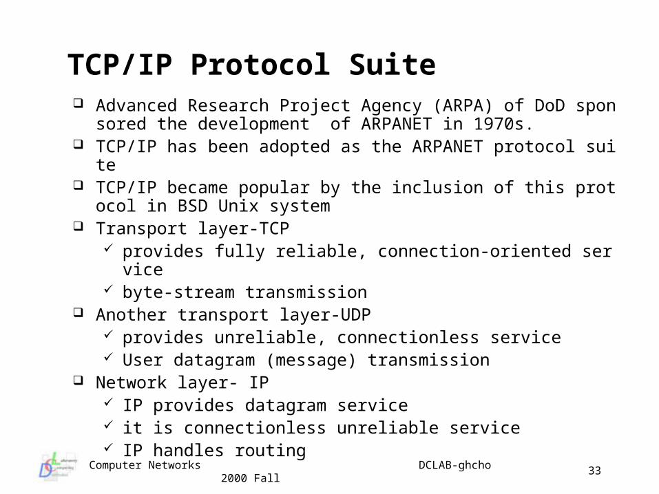
TCP/IP Protocol Suite Advanced Research Project Agency (ARPA) of DoD sponsored
the development of ARPANET in 1970s. TCP/IP has been adopted as the ARPANET protocol suite TCP/IP became popular by the inclusion of this protocol in BSD
Unix system Transport layer-TCP
provides fully reliable, connection-oriented service byte-stream transmission
Another transport layer-UDP provides unreliable, connectionless service User datagram (message) transmission
Network layer- IP IP provides datagram service it is connectionless unreliable service IP handles routing
Computer Networks DCLAB-ghcho 2000 Fall
34
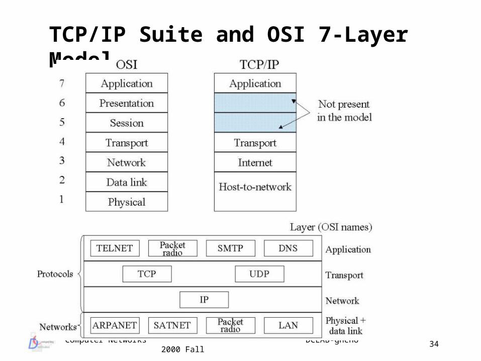
TCP/IP Suite and OSI 7-Layer Model
Computer Networks DCLAB-ghcho 2000 Fall
35
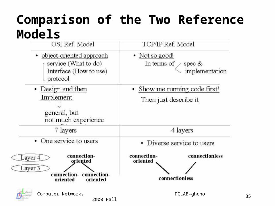
Comparison of the Two Reference Models
Computer Networks DCLAB-ghcho 2000 Fall
36
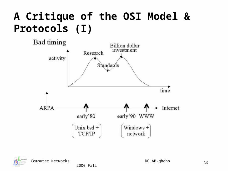
A Critique of the OSI Model & Protocols (I)
Computer Networks DCLAB-ghcho 2000 Fall
37
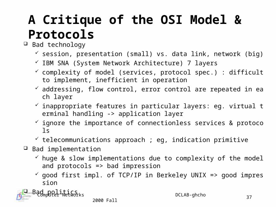
A Critique of the OSI Model & Protocols Bad technology
session, presentation (small) vs. data link, network (big) IBM SNA (System Network Architecture) 7 layers complexity of model (services, protocol spec.) : difficult to imple
ment, inefficient in operation addressing, flow control, error control are repeated in each layer inappropriate features in particular layers: eg. virtual terminal ha
ndling -> application layer ignore the importance of connectionless services & protocols telecommunications approach ; eg, indication primitive
Bad implementation huge & slow implementations due to complexity of the model an
d protocols => bad impression good first impl. of TCP/IP in Berkeley UNIX => good impression
Bad politics
Computer Networks DCLAB-ghcho 2000 Fall
38
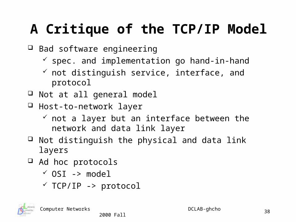
A Critique of the TCP/IP Model Bad software engineering
spec. and implementation go hand-in-hand not distinguish service, interface, and protocol
Not at all general model Host-to-network layer
not a layer but an interface between the network and data link layer
Not distinguish the physical and data link layers Ad hoc protocols
OSI -> model TCP/IP -> protocol
Computer Networks DCLAB-ghcho 2000 Fall
39
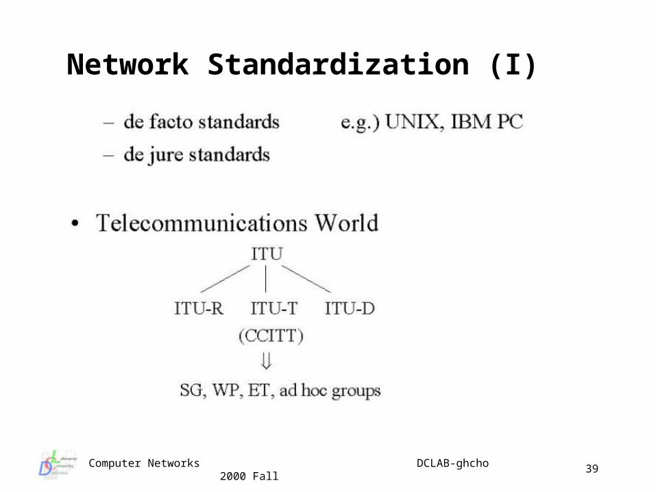
Network Standardization (I)
Computer Networks DCLAB-ghcho 2000 Fall
40
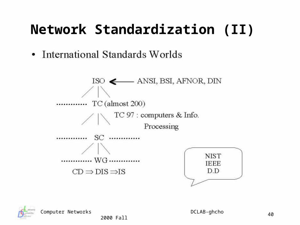
Network Standardization (II)
Computer Networks DCLAB-ghcho 2000 Fall
41
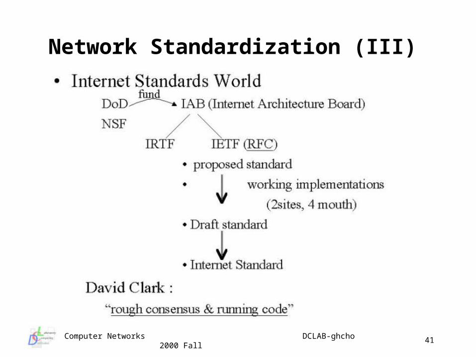
Network Standardization (III)
Computer Networks DCLAB-ghcho 2000 Fall
42
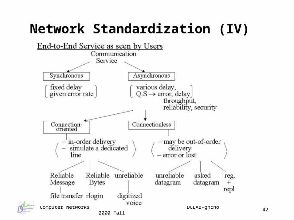
Network Standardization (IV)
Computer Networks DCLAB-ghcho 2000 Fall
43
Lecture Topic 2
Physical Layer
Physical layer functions Support for framing of information Analog and digital transmission Transmission media Switching techniques Integrated Services Digital Network (ISDN) xDSL: x Digital Subscriber Line Technologies Asynchronous Transfer Mode (ATM) Networks
Computer Networks DCLAB-ghcho 2000 Fall
44
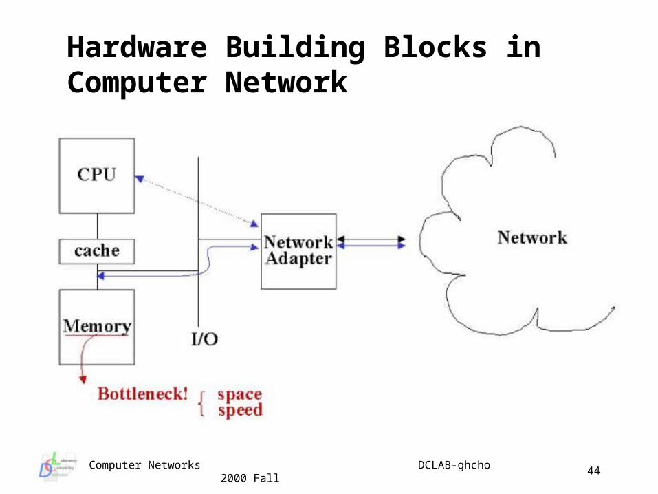
Hardware Building Blocks in Computer Network
Computer Networks DCLAB-ghcho 2000 Fall
45
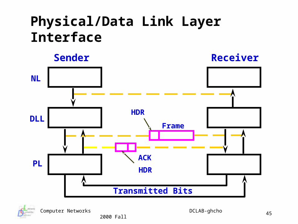
Physical/Data Link Layer Interface
NL
DLL
PL
Frame
HDR
ACK
HDR
Sender Receiver
Transmitted Bits
Computer Networks DCLAB-ghcho 2000 Fall
46
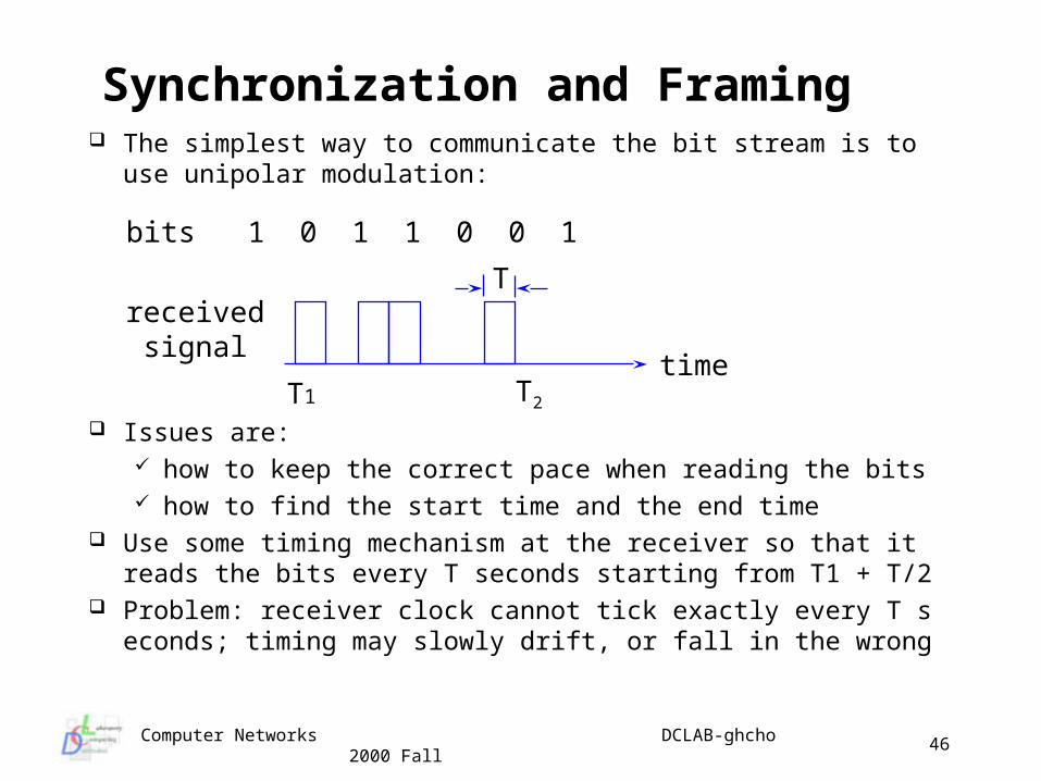
Synchronization and Framing The simplest way to communicate the bit stream is to use unipo
lar modulation:
Issues are: how to keep the correct pace when reading the bits how to find the start time and the end time
Use some timing mechanism at the receiver so that it reads the bits every T seconds starting from T1 + T/2
Problem: receiver clock cannot tick exactly every T seconds; timing may slowly drift, or fall in the wrong
bits 1 0 1 1 0 0 1
receivedsignal
time
T
T1 T2
Computer Networks DCLAB-ghcho 2000 Fall
47
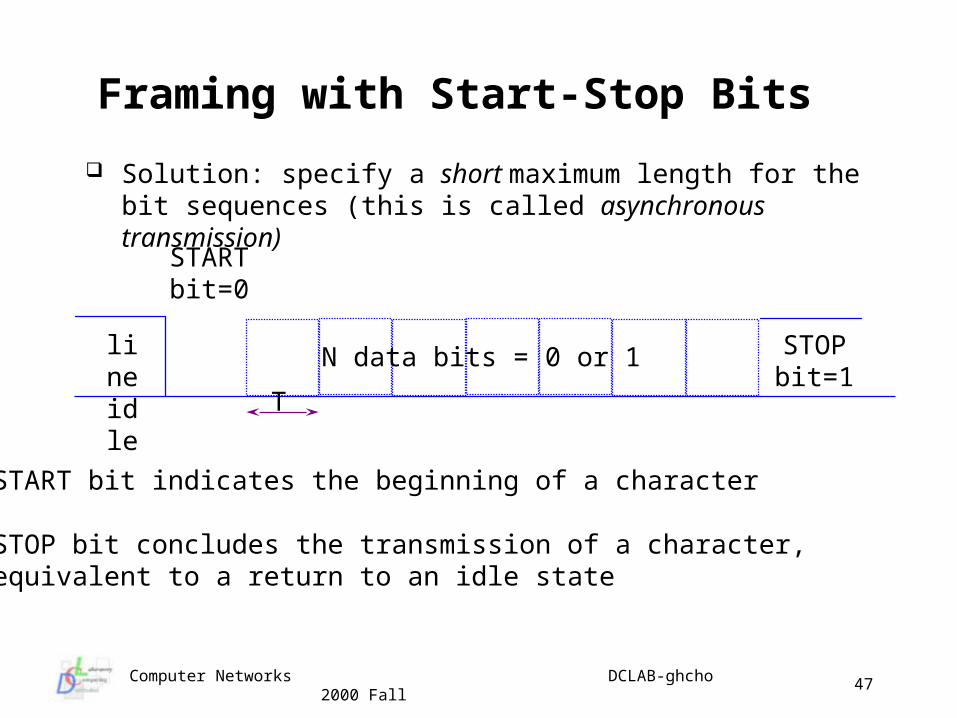
Framing with Start-Stop Bits
STARTbit=0
STOPbit=1
T
lineidle
N data bits = 0 or 1
START bit indicates the beginning of a character
STOP bit concludes the transmission of a character, equivalent to a return to an idle state
Solution: specify a short maximum length for the bit sequences (this is called asynchronous transmission)
Computer Networks DCLAB-ghcho 2000 Fall
48
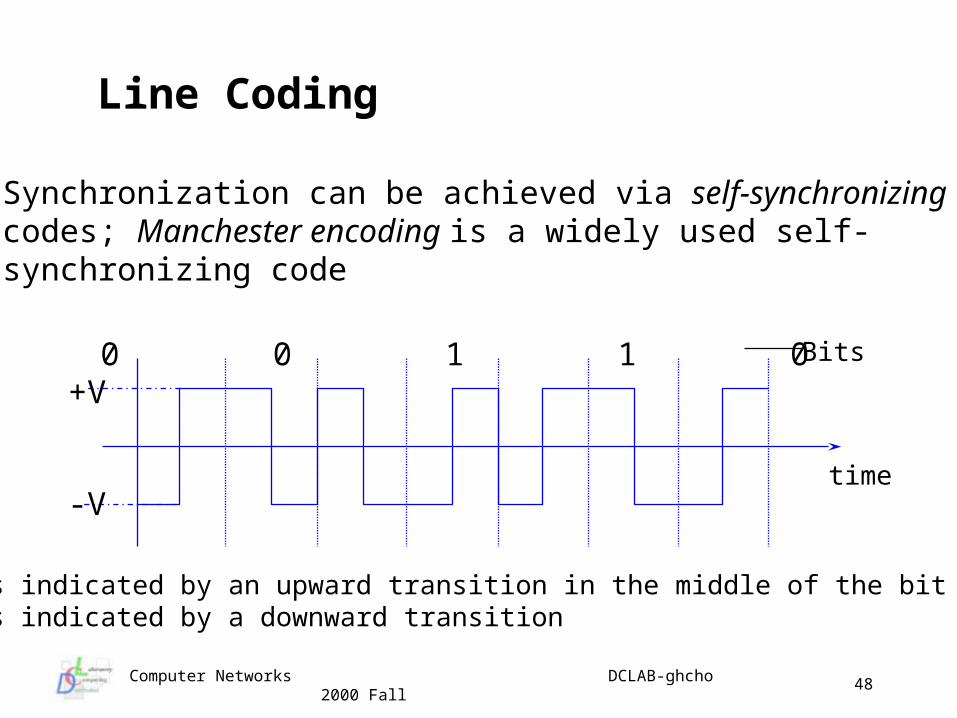
Line Coding
Synchronization can be achieved via self-synchronizingcodes; Manchester encoding is a widely used self-synchronizing code
1 0 0 1 1 0 1
time
Bits
Bit 1 is indicated by an upward transition in the middle of the bit time,Bit 0 is indicated by a downward transition
+V
-V
Computer Networks DCLAB-ghcho 2000 Fall
49
Analog and Digital Transmission
Definition analog signal : represents information with a continuously var
ying electromagnetic wave, e.g. telephone, TV digital signal : represents information with a sequence of volta
ge pulses, e.g. computer carrier signal : an analog electromagnetic wave that carries in
formation modulation : the process of encoding onto a carrier signal
A/D conversion converts an analog signal into a digital signal, required 3 steps
• sampling• quantization• coding
Computer Networks DCLAB-ghcho 2000 Fall
50
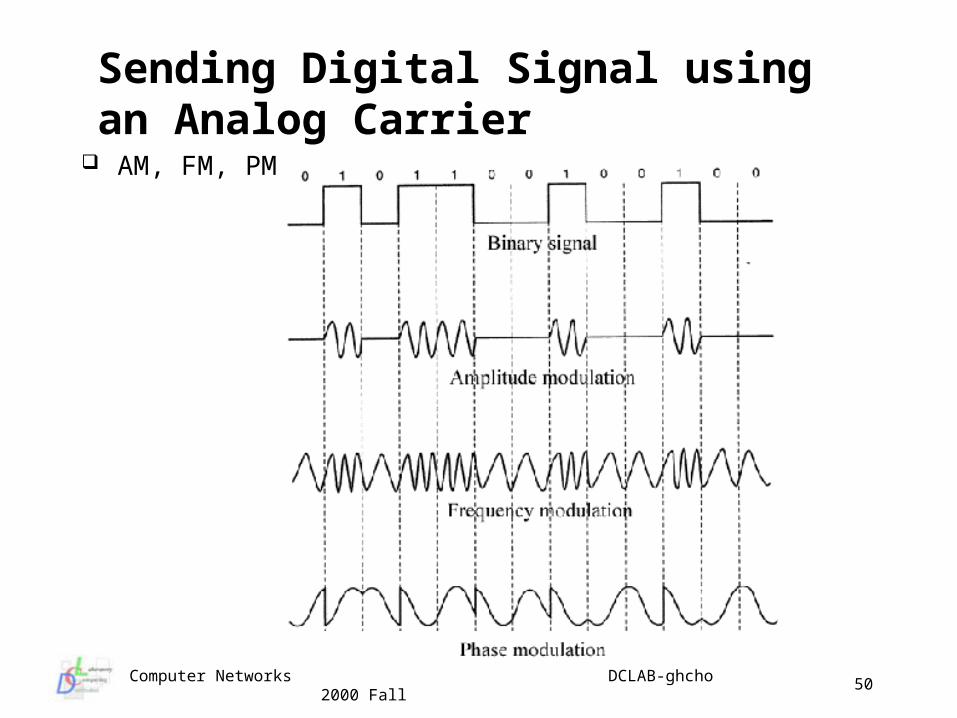
Sending Digital Signal using an Analog Carrier
AM, FM, PM
Computer Networks DCLAB-ghcho 2000 Fall
51
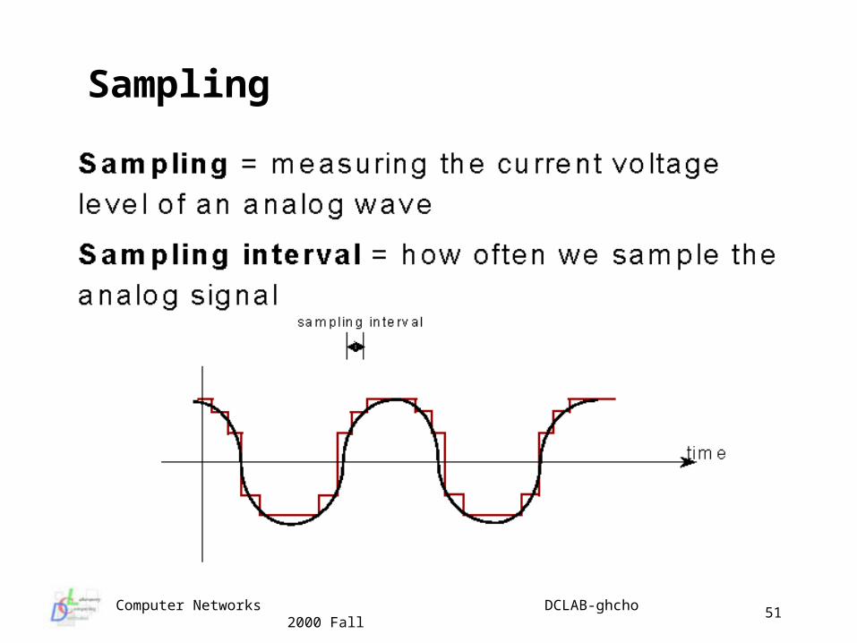
Sampling
Computer Networks DCLAB-ghcho 2000 Fall
52
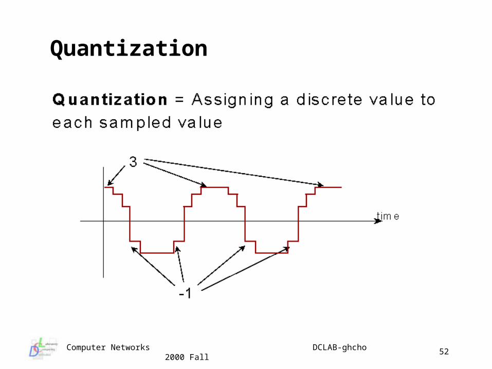
Quantization
Computer Networks DCLAB-ghcho 2000 Fall
53
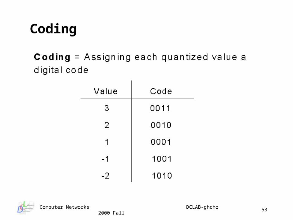
Coding
Computer Networks DCLAB-ghcho 2000 Fall
54
Transmission Media : Twisted Pair Copper
Very common media is twisted pair usually 2 copper wires (~ 1mm diameter) shielded (STP)
or unshielded (UTP) twisting reduces tendency to become an antenna ubiquitous because of the telephone system can be used for analog or digital transmission usually require amplifiers (for analog) or repeaters
(digital) every few kilometers bandwidth related to distance and thickness but Mbps are
possible
Computer Networks DCLAB-ghcho 2000 Fall
55
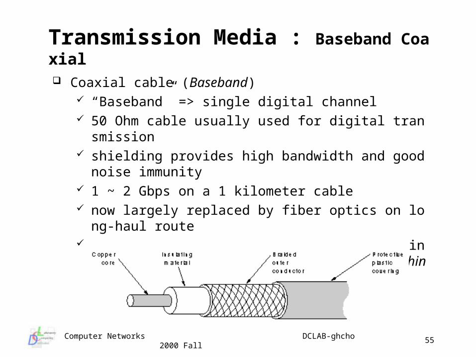
Transmission Media : Baseband Coaxial
Coaxial cable (Baseband) “Baseband” => single digital channel 50 Ohm cable usually used for digital transmission shielding provides high bandwidth and good noise immuni
ty 1 ~ 2 Gbps on a 1 kilometer cable now largely replaced by fiber optics on long-haul route used for cable television and some original 10 base Ether
net and for 10 base T (Thinwire)
Computer Networks DCLAB-ghcho 2000 Fall
56
Transmission Media : Broadband Coaxial Coaxial cable (Broadband)
75 Ohm used for analog transmission can transmit 300 MHz for long distances (100 km) digital signal requires analog transceivers divides bandwidth into multiple channels channels can transmit TV, audio or digital and mix digital and an
alog transmissions (6Mhz for a TV channel) inferior to baseband but lots of cable in place due to historical de
velopment of broadcasting (so analog amplifiers are required) directional transmission => 2 cables (transmit and receive) in a tr
ee structure, or a single cable with two frequency bands : different ways to alloca
te frequency bands- subsplit 5-30 MHz for inbound and 40-300 MHz for outbound- midsplit 5-116 MHz for inbound and 168-300 MHz for outbound
Computer Networks DCLAB-ghcho 2000 Fall
57
Transmission Media : Fiber Optics (I)
Fiber Optic cable properties of refraction allow light to be trapped inside a sl
ender glass strand and propagate for very long distances with little loss
may use LED(Light Emitting Diode)s (cheaper - usually with multi-mode) or Lasers (expensive - usually with single mode)
depending on diameter of fiber and wavelength of light there may be multiple paths for a given light ray depending on incident angle of refraction (multi-mode fiber - usually 62.5 micron core) or there may be just a single path (single-mode fiber - usually 8 micron core)
multi-mode is cheaper and more common and gives up to 500 Mbps at 2-4 kilometers
Computer Networks DCLAB-ghcho 2000 Fall
58
Transmission Media : Fiber Optics (II)
single-mode is more expensive and gives up to 2 Gbps to about 30 kilometers
attenuation depends on wavelength of light and there are 3 nice windows (.85, 1.3 and 1.55 micron - most devices use first or second)
light disperses (signal smears out) especially in multi-mode since individual rays take paths of different lengths
fiber requires electro-optics for conversion of electrical signals to/from optical signals
often use Active Repeaters and ring topology or passive star topology to distribute signals (divides signal power among the arms)
fiber is immune to thermal noise
Computer Networks DCLAB-ghcho 2000 Fall
59
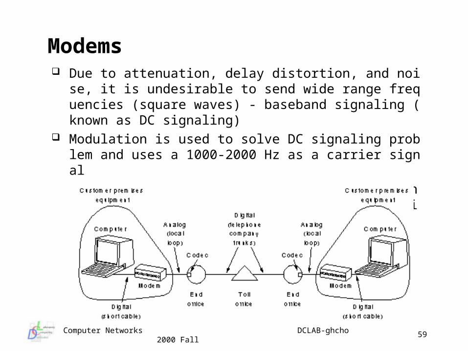
Modems Due to attenuation, delay distortion, and noise, it is undesirab
le to send wide range frequencies (square waves) - baseband signaling (known as DC signaling)
Modulation is used to solve DC signaling problem and uses a 1000-2000 Hz as a carrier signal Amplitude Modulation, Frequency Modulation, (frequency
shift keying), phase modulation, etc.
Computer Networks DCLAB-ghcho 2000 Fall
60
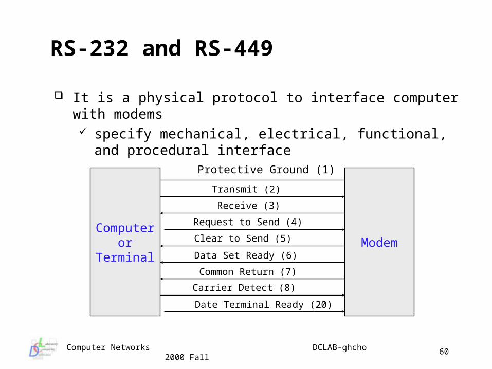
RS-232 and RS-449
It is a physical protocol to interface computer with modems specify mechanical, electrical, functional, and procedural
interface
Computeror
TerminalModem
Protective Ground (1)
Transmit (2)
Receive (3)
Request to Send (4)
Clear to Send (5)
Data Set Ready (6)
Common Return (7)
Carrier Detect (8)
Date Terminal Ready (20)
Computer Networks DCLAB-ghcho 2000 Fall
61
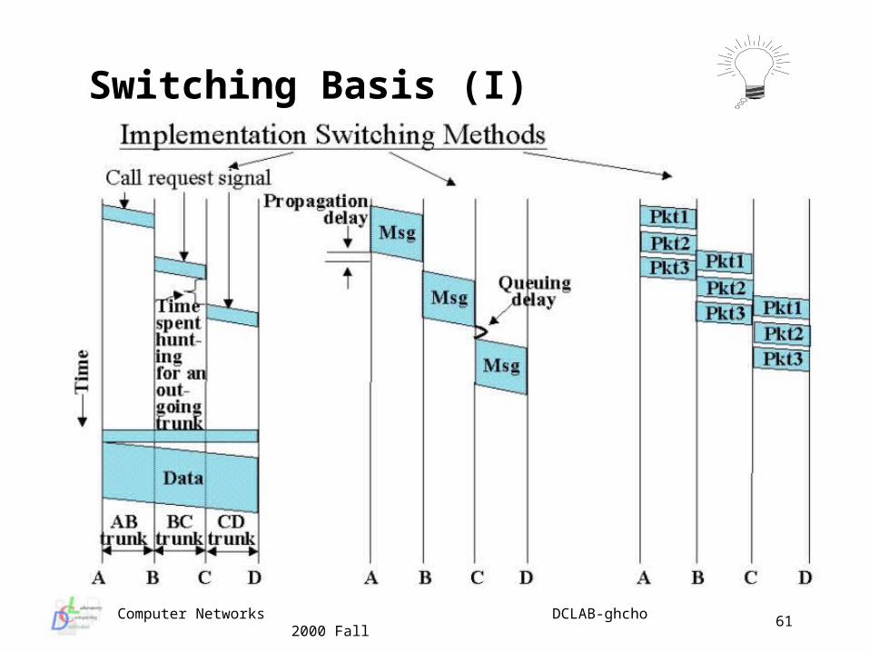
Switching Basis (I)
Computer Networks DCLAB-ghcho 2000 Fall
62
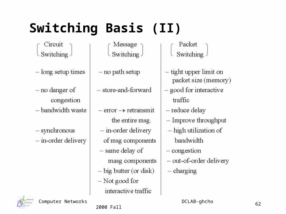
Switching Basis (II)
Computer Networks DCLAB-ghcho 2000 Fall
63
Circuit Switching (I) Circuit Switching
communications is done via a dedicated path between end stations
this path is a sequence of links between intermediate nodes
three phases are required: Circuit Establishment (Call Setup) : end station A
requests connection to end station B results in sequence of connection establishments
Data Transfer : information is transmitted in analog or binary format
Circuit Disconnection : sequence of disconnection of individual links
Computer Networks DCLAB-ghcho 2000 Fall
64
Circuit Switching (II) Need circuit setup end-to-end before any data transfer can tak
e place disadvantage: setup may introduce appreciable delay advantage: after set up there is usually low delay and little
variance in delay - effectively a wire Characteristics good for voice so wide spread because of voic
e and the PSTN Not optimal for many digital applications but can be expected t
o continue to be widely used in WANs As you might suspect a key device is the Switch!
generally digital in modern switches several different technologies for switching carrier charges based on distance and call time
Computer Networks DCLAB-ghcho 2000 Fall
65
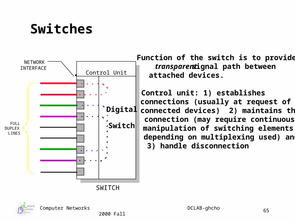
Switches
Function of the switch is to provide atransparent signal path betweenattached devices.
Control unit: 1) establishesconnections (usually at request ofconnected devices) 2) maintains theconnection (may require continuousmanipulation of switching elementsdepending on multiplexing used) and3) handle disconnection
Control Unit
Digital
Switch
NETWORKINTERFACE
FULLDUPLEX
LINES
SWITCH
Computer Networks DCLAB-ghcho 2000 Fall
66
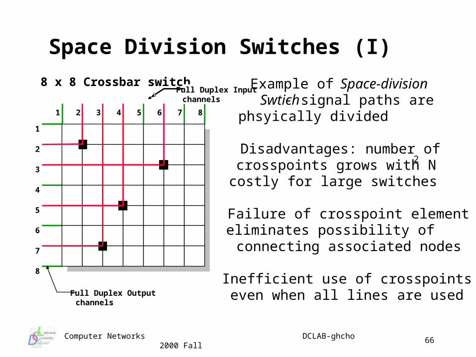
Space Division Switches (I)
Example of Space-divisionSwtich - signal paths arephsyically divided
Disadvantages: number ofcrosspoints grows with N2
costly for large switches
Failure of crosspoint elementeliminates possibility ofconnecting associated nodes
Inefficient use of crosspointseven when all lines are used
1 2 3 4 5 6 7 8
1
2
3
4
5
6
7
8
8 x 8 Crossbar switchFull Duplex Inputchannels
Full Duplex Outputchannels
Computer Networks DCLAB-ghcho 2000 Fall
67
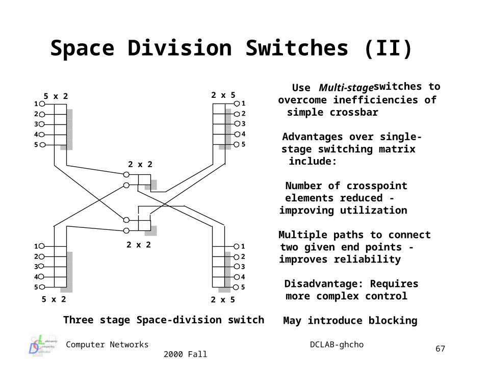
Space Division Switches (II)
Use Multi-stage switches toovercome inefficiencies ofsimple crossbar
Advantages over single-stage switching matrixinclude:
Number of crosspointelements reduced -improving utilization
Multiple paths to connecttwo given end points -improves reliability
Disadvantage: Requiresmore complex control
May introduce blocking
1
2
3
4
5
1
2
3
4
5
1
2
3
4
5
1
2
3
4
5
5 x 2
5 x 2
2 x 2
2 x 2
2 x 5
2 x 5
Three stage Space-division switch
Computer Networks DCLAB-ghcho 2000 Fall
68
Packet Switches (I) Packet Switching
unlike voice traffic, computer interactions usually involve long periods of idle time - making circuit switching inefficient
circuit switching requires the two end stations to talk at the same data rate
a solution to these problems is to break up the communication into chunks with a relatively small maximum size - will store temporarily at intermediate system
now we must add some control information to each packet so it can be routed through the network
send the packet through sequence to intermediate systems to get from source to destination
Computer Networks DCLAB-ghcho 2000 Fall
69
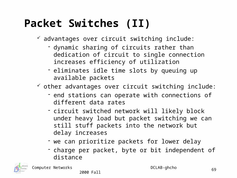
Packet Switches (II) advantages over circuit switching include:
dynamic sharing of circuits rather than dedication of circuit to single connection increases efficiency of utilization
eliminates idle time slots by queuing up available packets
other advantages over circuit switching include: end stations can operate with connections of different
data rates circuit switched network will likely block under heavy
load but packet switching we can still stuff packets into the network but delay increases
we can prioritize packets for lower delay charge per packet, byte or bit independent of distance
Computer Networks DCLAB-ghcho 2000 Fall
70
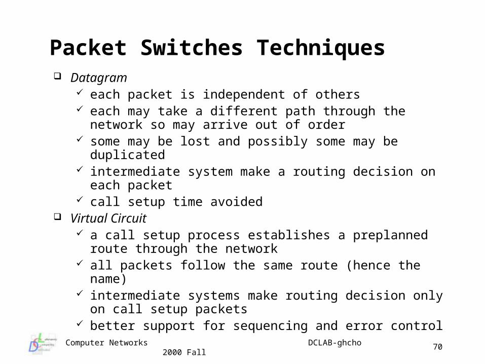
Packet Switches Techniques Datagram
each packet is independent of others each may take a different path through the network so
may arrive out of order some may be lost and possibly some may be duplicated intermediate system make a routing decision on each
packet call setup time avoided
Virtual Circuit a call setup process establishes a preplanned route
through the network all packets follow the same route (hence the name) intermediate systems make routing decision only on call
setup packets better support for sequencing and error control
Computer Networks DCLAB-ghcho 2000 Fall
71
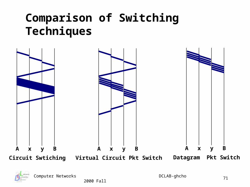
Comparison of Switching Techniques
Circuit Swtiching
A x y B
Datagram Pkt Switch
A x y B A x y B
Virtual Circuit Pkt Switch
Computer Networks DCLAB-ghcho 2000 Fall
72
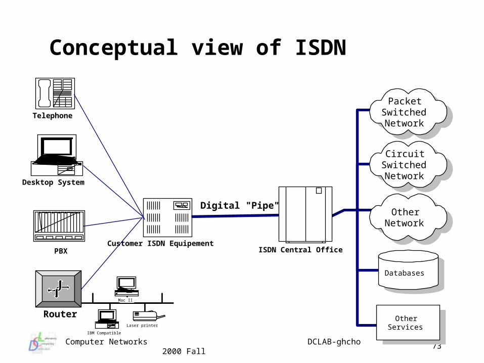
Narrowband ISDN Mid 1980’s the telecomm’s decided to invent the replacement
for the analog phone system in anticipation of customer demand for end-to-end digital service
Since it was to provide integrated voice and non-voice service they called it Integrated Services Digital Network - ISDN
Use on a limited set of standardized facilities Support for both circuit switching and packet switching Based on 64 kbps connections - fundamental building block of
ISDN (hence “narrowband”) Provide intelligent services Layered architecture which can be mapped to OSI Variety of physical configurations
Computer Networks DCLAB-ghcho 2000 Fall
73
Conceptual view of ISDN
PacketSwitchedNetwork
CircuitSwitchedNetwork
OtherNetwork
Databases
OtherServices
ISDN Central OfficeCustomer ISDN Equipement
Desktop System
Telephone
PBX
Router
IBM Compatible
Mac II
Laser printer
Digital "Pipe"
Computer Networks DCLAB-ghcho 2000 Fall
74
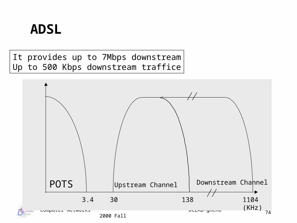
ADSL
POTS Upstream Channel Downstream Channel
3.4 30 138 1104(KHz)
It provides up to 7Mbps downstreamUp to 500 Kbps downstream traffice
Computer Networks DCLAB-ghcho 2000 Fall
75
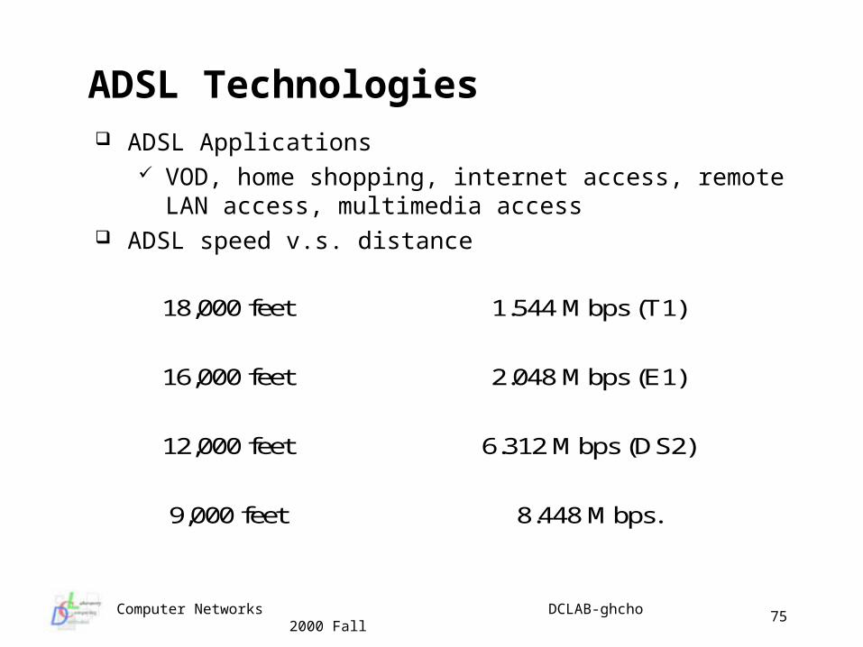
ADSL Technologies ADSL Applications
VOD, home shopping, internet access, remote LAN access, multimedia access
ADSL speed v.s. distance
18,000 feet 1.544 Mbps (T1)
16,000 feet 2.048 Mbps (E1)
12,000 feet 6.312 Mbps (DS2)
9,000 feet 8.448 Mbps.
Computer Networks DCLAB-ghcho 2000 Fall
76
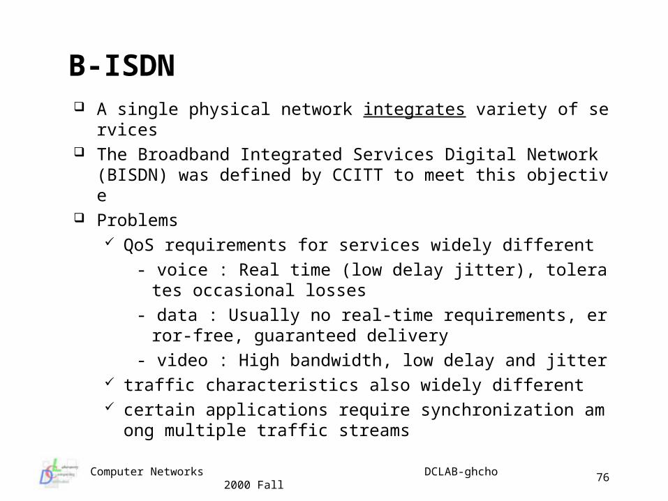
B-ISDN A single physical network integrates variety of services The Broadband Integrated Services Digital Network (BISDN)
was defined by CCITT to meet this objective Problems
QoS requirements for services widely different
- voice : Real time (low delay jitter), tolerates occasional losses
- data : Usually no real-time requirements, error-free, guaranteed delivery
- video : High bandwidth, low delay and jitter traffic characteristics also widely different certain applications require synchronization among multipl
e traffic streams
Computer Networks DCLAB-ghcho 2000 Fall
77
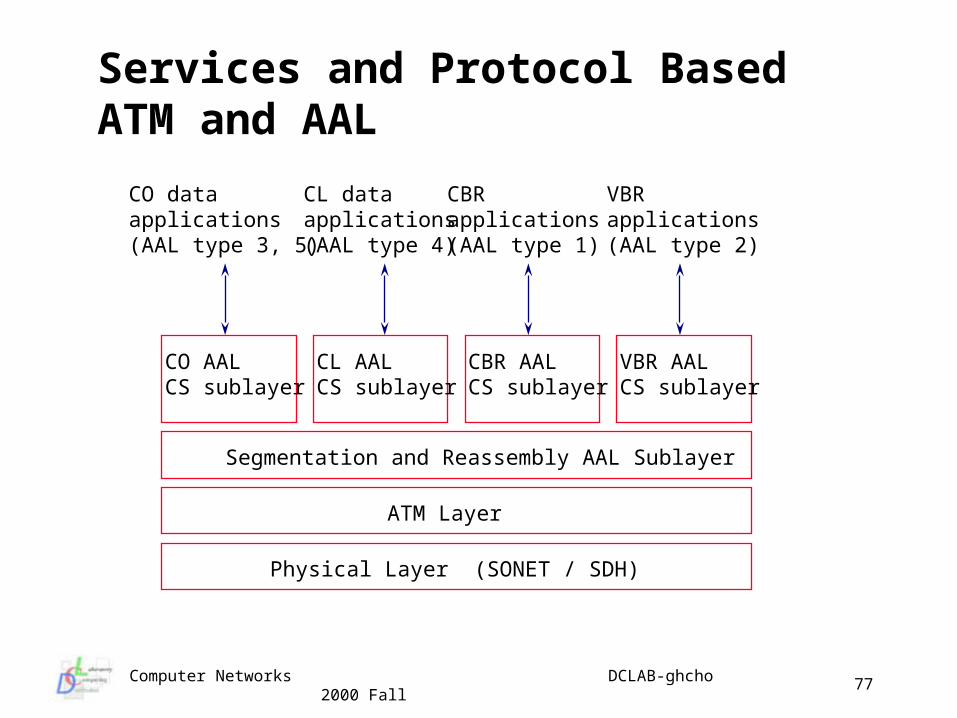
Services and Protocol Based ATM and AAL
CO AALCS sublayer
CL AALCS sublayer
CBR AALCS sublayer
VBR AALCS sublayer
Segmentation and Reassembly AAL Sublayer
ATM Layer
Physical Layer (SONET / SDH)
CO data applications(AAL type 3, 5)
CL data applications(AAL type 4)
CBR applications(AAL type 1)
VBR applications(AAL type 2)
Computer Networks DCLAB-ghcho 2000 Fall
78
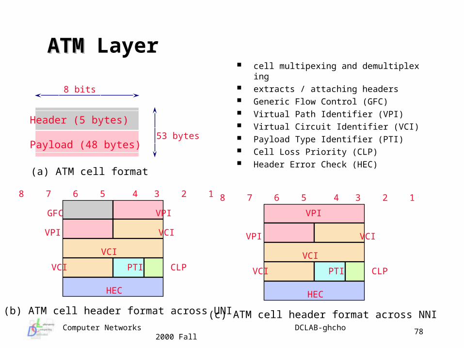
ATMATM Layer cell multipexing and demultiplexing extracts / attaching headers Generic Flow Control (GFC) Virtual Path Identifier (VPI) Virtual Circuit Identifier (VCI) Payload Type Identifier (PTI) Cell Loss Priority (CLP) Header Error Check (HEC)
Header (5 bytes)
Payload (48 bytes)
8 bits
53 bytes
GFC VPI
VPI VCI
VCI
VCI PTI CLP
HEC
8 7 6 5 4 3 2 1
VPI
VPI VCI
VCI
VCI PTI CLP
HEC
8 7 6 5 4 3 2 1
(a) ATM cell format
(b) ATM cell header format across UNI (c) ATM cell header format across NNI
Computer Networks DCLAB-ghcho 2000 Fall
79
Lecture Topic 3
Data Link Layer
Data Link Layer Functions Data Link Layer Design Issues Framing Techniques Error Detecting and Corrections Error control and flow control Media Access Control Sublayer Carrier Sense Multiple Access Protocols Standard LAN Protocols Bridges
Computer Networks DCLAB-ghcho 2000 Fall
80
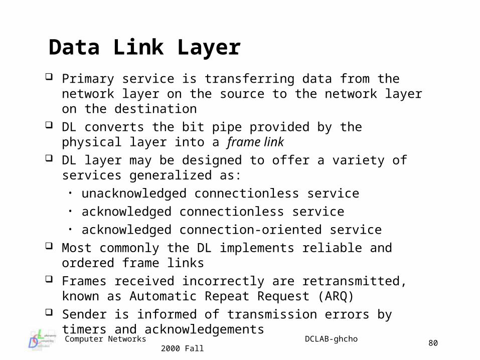
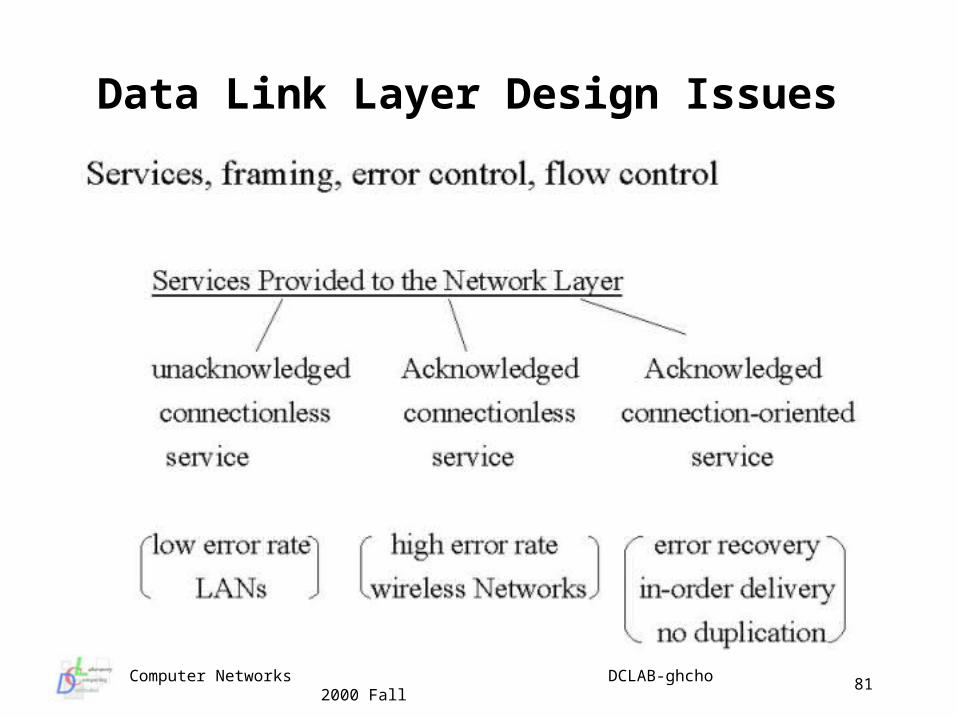
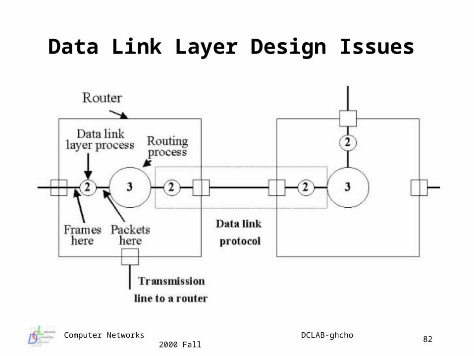
Data Link Layer Primary service is transferring data from the network layer on
the source to the network layer on the destination DL converts the bit pipe provided by the physical layer into a
frame link DL layer may be designed to offer a variety of services
generalized as:• unacknowledged connectionless service• acknowledged connectionless service• acknowledged connection-oriented service
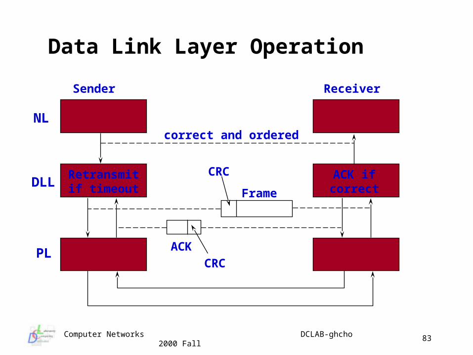
Most commonly the DL implements reliable and ordered frame links
Frames received incorrectly are retransmitted, known as Automatic Repeat Request (ARQ)
Sender is informed of transmission errors by timers and acknowledgements
Computer Networks DCLAB-ghcho 2000 Fall
81
Data Link Layer Design Issues
Computer Networks DCLAB-ghcho 2000 Fall
82
Data Link Layer Design Issues
Computer Networks DCLAB-ghcho 2000 Fall
83
Data Link Layer Operation
NL
DLL
PL
Retransmitif timeout
ACK ifcorrectFrame
CRC
ACK
CRC
Sender Receiver
correct and ordered
Computer Networks DCLAB-ghcho 2000 Fall
84
Framing in the DL Recall DL uses services provided by physical layer (raw bit
stream, not necessarily error free) Usually DL organizes the bit stream into discrete frames to
perform error detection on frames (perhaps by Checksum) How can we organize this bit stream when we may not have any
guarantees regarding timing (i.e. we can’t just insert gaps like the spaces between words - would waste bandwidth)?
Several methods are commonly used and we can use a combination of methods
Recall we usually add some protocol control information at each layer as a header (and maybe a trailer)
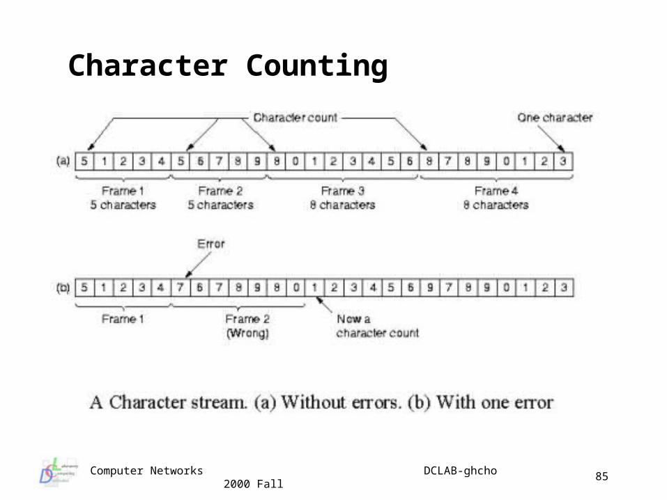
Many simple techniques developed for early ASCII character transmission character counting start/end characters
Computer Networks DCLAB-ghcho 2000 Fall
85
Character Counting
Computer Networks DCLAB-ghcho 2000 Fall
86
01111110 001111110100101011100111111100 01111110
01111110 00111110101001010111001111101100 01111110
01111110 001111110100101011100111111100 01111110
inserted 0 inserted 0
deleted 0 deleted 0
Stuffing
Destuffing
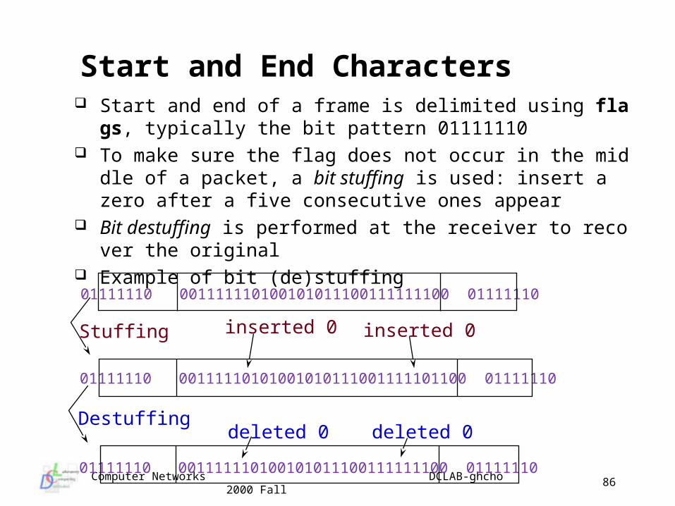
Start and end of a frame is delimited using flags, typically the bit pattern 01111110
To make sure the flag does not occur in the middle of a packet, a bit stuffing is used: insert a zero after a five consecutive ones appear
Bit destuffing is performed at the receiver to recover the original Example of bit (de)stuffing
Start and End Characters
Computer Networks DCLAB-ghcho 2000 Fall
87
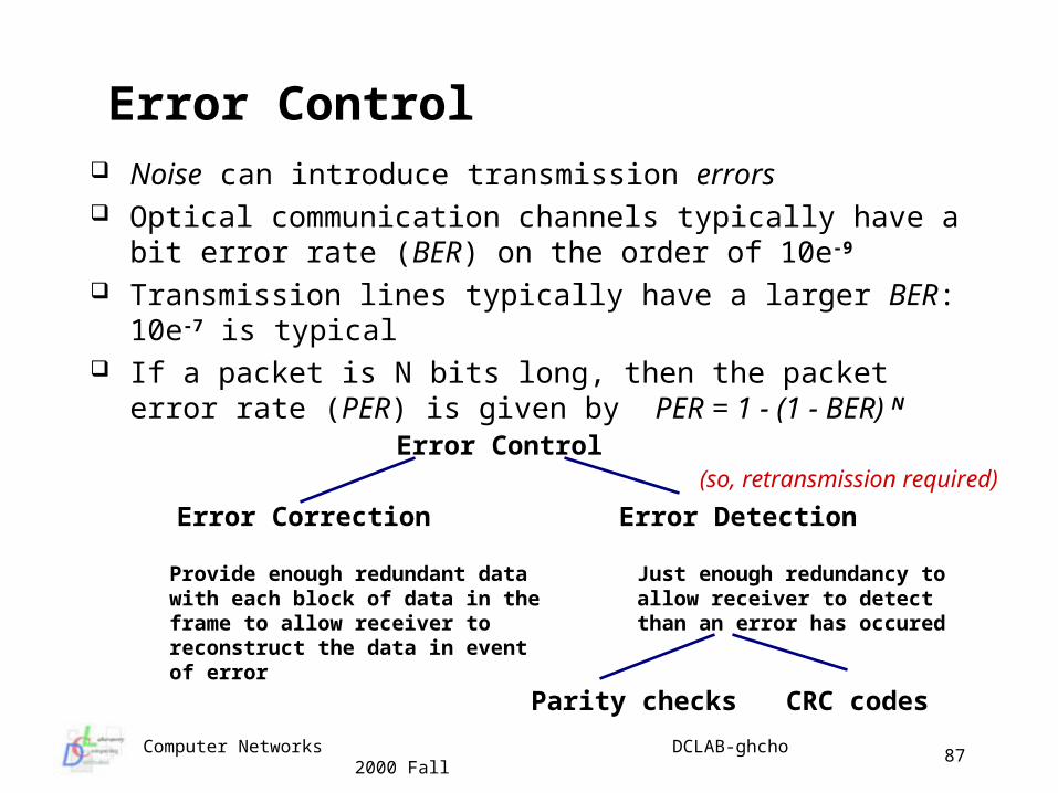
Error Control Noise can introduce transmission errors Optical communication channels typically have a bit error rate
(BER) on the order of 10e-9
Transmission lines typically have a larger BER: 10e-7 is typical If a packet is N bits long, then the packet error rate (PER) is given
by PER = 1 - (1 - BER) N
Error Control
Error Correction Error Detection
Parity checks CRC codes
Provide enough redundant data with each block of data in the frame to allow receiver to reconstruct the data in event of error
Just enough redundancy to allow receiver to detect than an error has occured
(so, retransmission required)
Computer Networks DCLAB-ghcho 2000 Fall
88
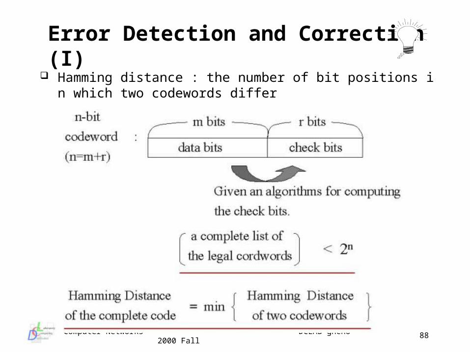
Error Detection and Correction (I) Hamming distance : the number of bit positions in which two code
words differ
Computer Networks DCLAB-ghcho 2000 Fall
89
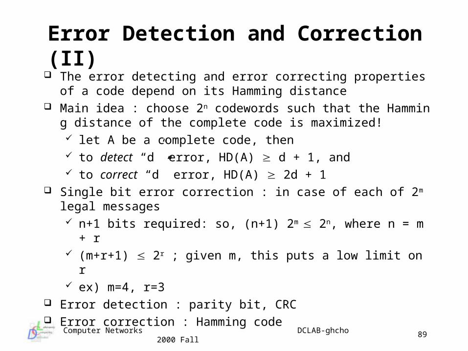
Error Detection and Correction (II) The error detecting and error correcting properties of a code dep
end on its Hamming distance Main idea : choose 2n codewords such that the Hamming distanc
e of the complete code is maximized! let A be a complete code, then to detect “d” error, HD(A) d + 1, and to correct “d” error, HD(A) 2d + 1
Single bit error correction : in case of each of 2m legal messages n+1 bits required: so, (n+1) 2m 2n, where n = m + r (m+r+1) 2r ; given m, this puts a low limit on r ex) m=4, r=3
Error detection : parity bit, CRC Error correction : Hamming code
Computer Networks DCLAB-ghcho 2000 Fall
90
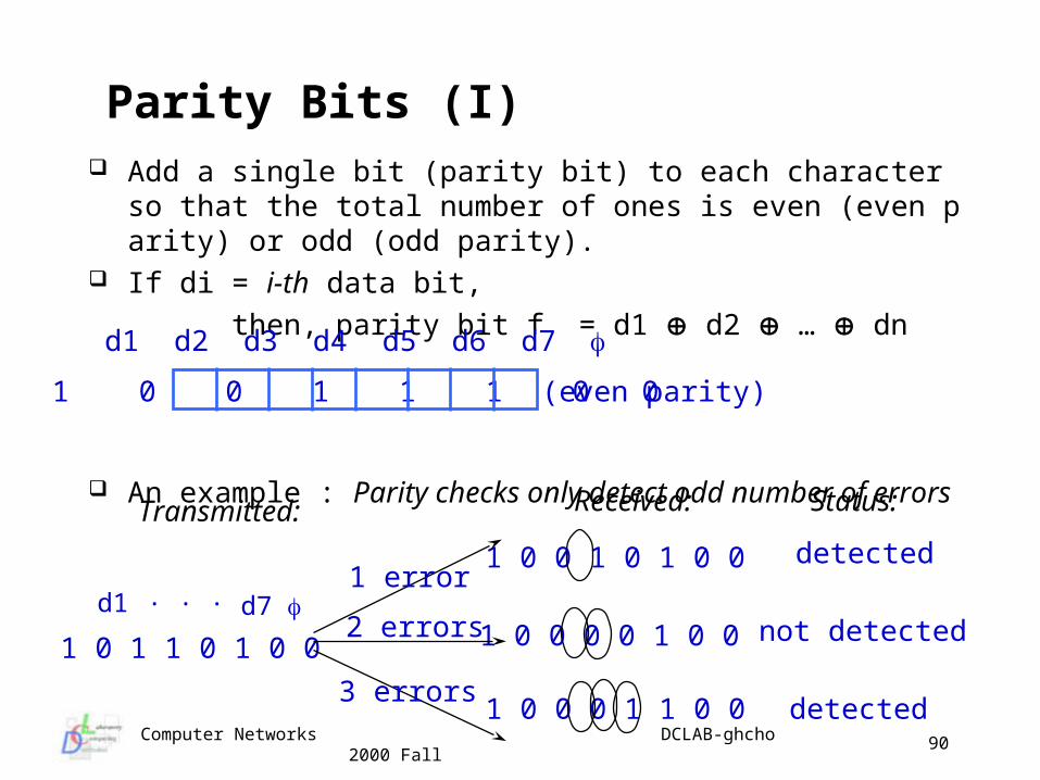
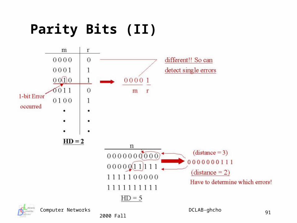
Parity Bits (I) Add a single bit (parity bit) to each character so that the total num
ber of ones is even (even parity) or odd (odd parity). If di = i-th data bit,
then, parity bit f = d1 d2 … dn
An example : Parity checks only detect odd number of errors
d1 d2 d3 d4 d5 d6 d7
1 0 0 1 1 1 0 0 (even parity)
Transmitted: Received:
1 0 1 1 0 1 0 0
d1 d7 . . .
1 0 0 1 0 1 0 0
1 0 0 0 0 1 0 0
1 0 0 0 1 1 0 0
1 error
2 errors
3 errors
Status:
detected
not detected
detected
Computer Networks DCLAB-ghcho 2000 Fall
91
Parity Bits (II)
Computer Networks DCLAB-ghcho 2000 Fall
92
Cyclic Redundancy Code (CRC) Powerful method : used in most computer networks Small amount of hardware required Consider a message m = 11011001 (where the left-most bit repr
esents the most significant bit : big endian) the corresponding polynomial representation of the message
is: M(X) = X7 + X6 + X4 + X3 + 1• G(x) : degree r (r+1 bits) generator polynomial• R(x) : CRC polynomial, r bits• T(x) : text transmitted
Addition, subtraction, multiplication and division of polynomials are done with modulo two arithmetic
Computer Networks DCLAB-ghcho 2000 Fall
93
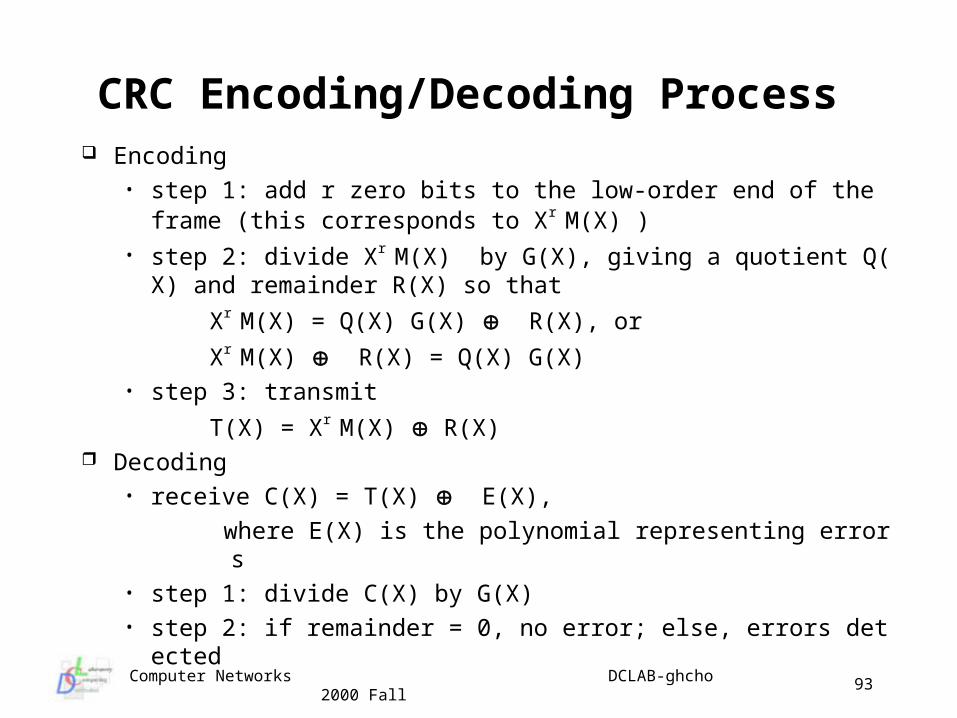
CRC Encoding/Decoding Process Encoding
• step 1: add r zero bits to the low-order end of the frame (this corresponds to Xr M(X) )
• step 2: divide Xr M(X) by G(X), giving a quotient Q(X) and remainder R(X) so that
Xr M(X) = Q(X) G(X) R(X), or
Xr M(X) R(X) = Q(X) G(X)• step 3: transmit
T(X) = Xr M(X) R(X) Decoding
• receive C(X) = T(X) E(X),
where E(X) is the polynomial representing errors• step 1: divide C(X) by G(X)• step 2: if remainder = 0, no error; else, errors detected
Computer Networks DCLAB-ghcho 2000 Fall
94
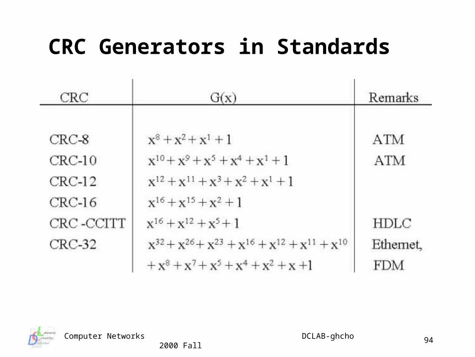
CRC Generators in Standards
Computer Networks DCLAB-ghcho 2000 Fall
95
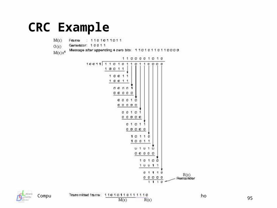
CRC Example
Computer Networks DCLAB-ghcho 2000 Fall
96
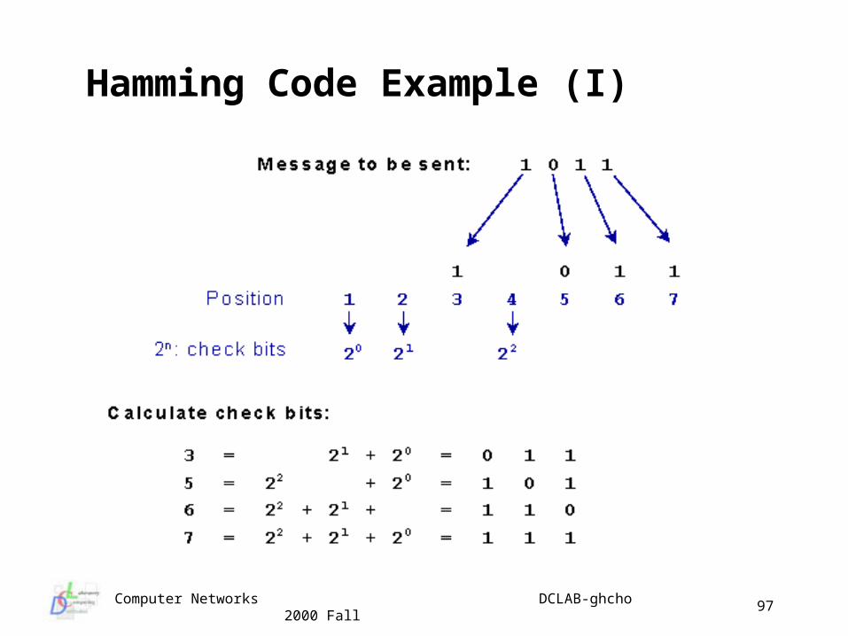
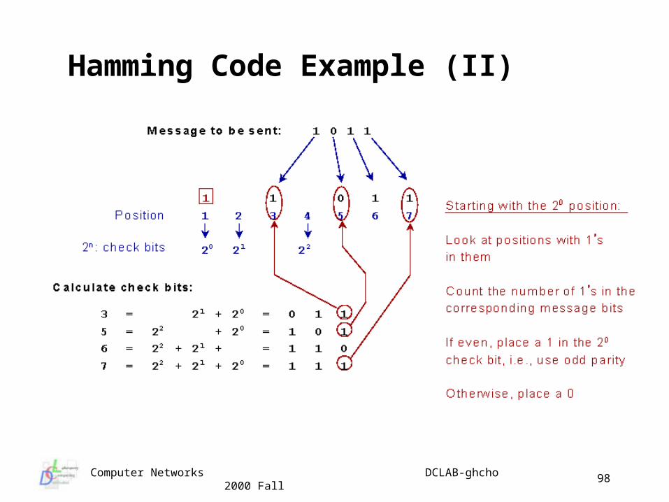
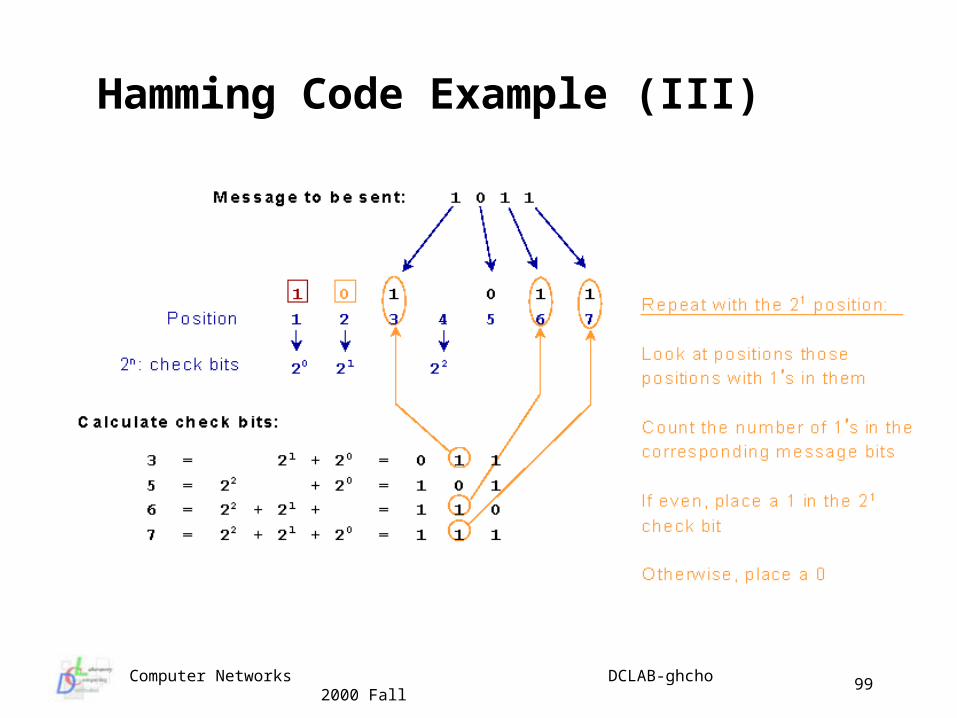
Hamming Code Parity bit and CRC catch errors, but can we correct them without
retransmitting information? =: Hamming code Hamming codes, unlike CRC, contain the information necess
ary to locate a single bit error Procedure
place message bits in their non-power-of-two Hamming positions
build a table listing the binary representation each of the message bit positions
calculate the check bit Hamming code
check bits : b1, b2, b4, b8, b16, ….
data bits : b3, b5, b6, b7, b9, ….
Computer Networks DCLAB-ghcho 2000 Fall
97
Hamming Code Example (I)
Computer Networks DCLAB-ghcho 2000 Fall
98
Hamming Code Example (II)
Computer Networks DCLAB-ghcho 2000 Fall
99
Hamming Code Example (III)
Computer Networks DCLAB-ghcho 2000 Fall
100
Hamming Code Example (IV)
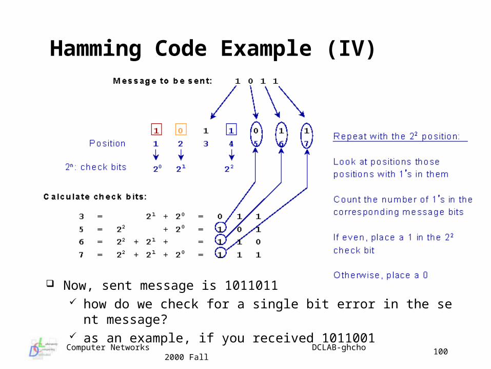
Now, sent message is 1011011 how do we check for a single bit error in the sent message? as an example, if you received 1011001
Computer Networks DCLAB-ghcho 2000 Fall
101
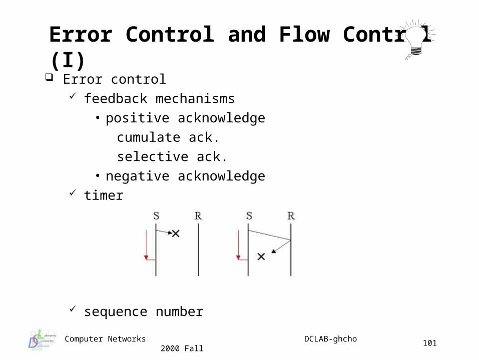
Error Control and Flow Control (I) Error control
feedback mechanisms • positive acknowledge
cumulate ack.
selective ack.• negative acknowledge
timer
sequence number
Computer Networks DCLAB-ghcho 2000 Fall
102
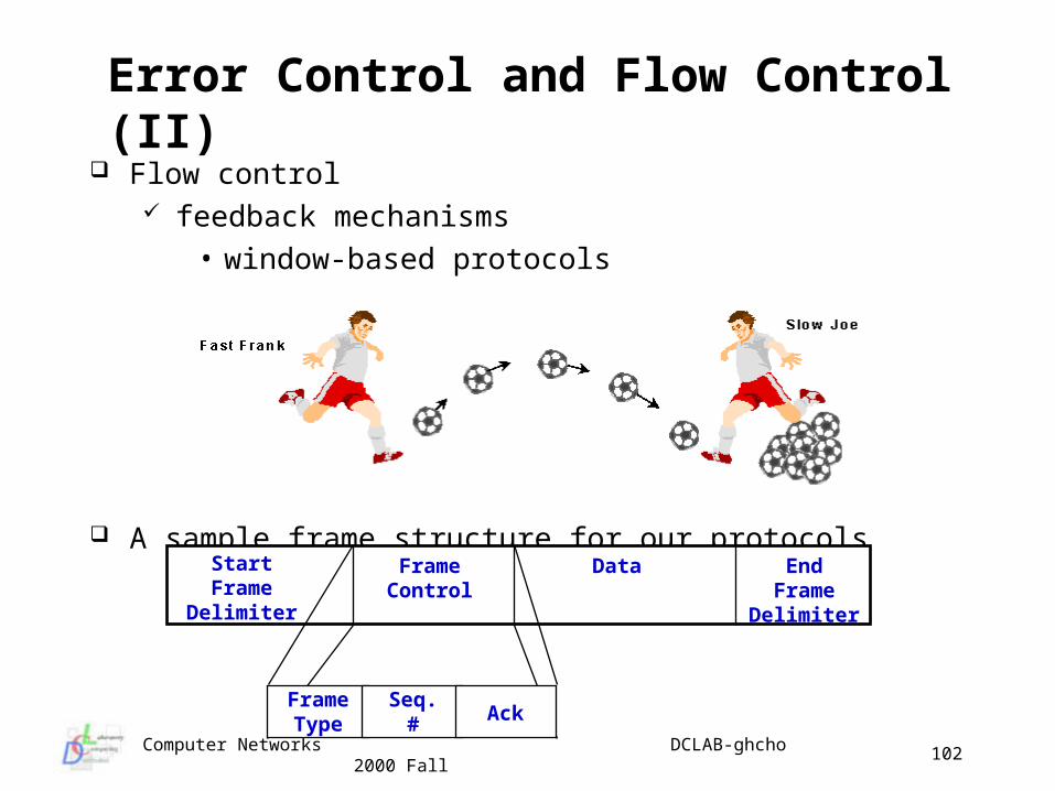
Error Control and Flow Control (II) Flow control
feedback mechanisms • window-based protocols
A sample frame structure for our protocols
StartFrame
Delimiter
FrameControl
Data EndFrame
Delimiter
FrameType
Seq.# Ack
Computer Networks DCLAB-ghcho 2000 Fall
103
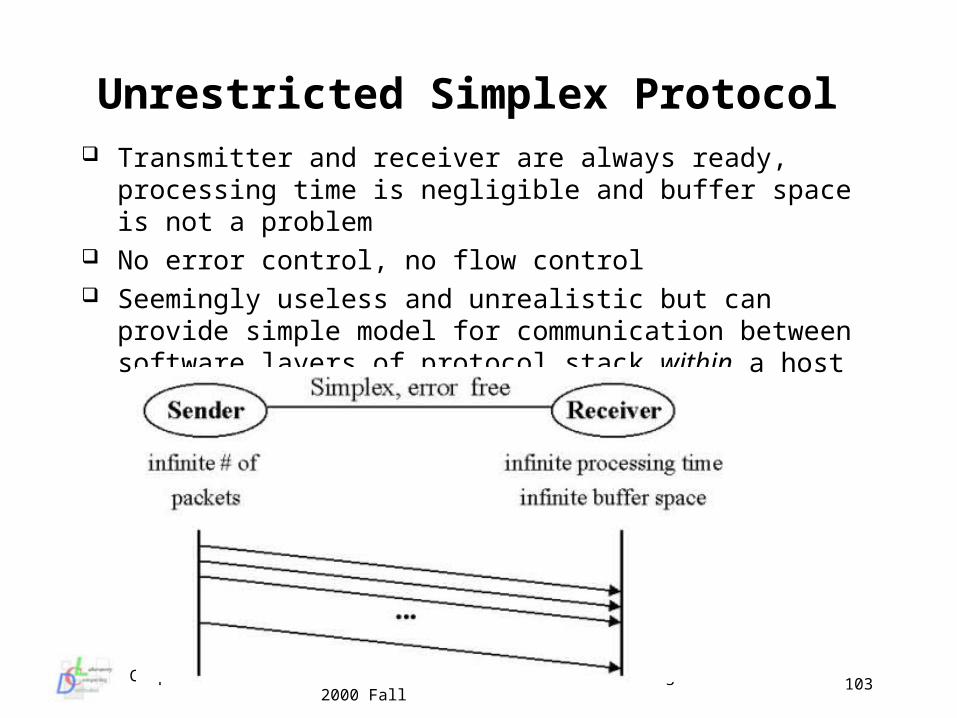
Unrestricted Simplex Protocol Transmitter and receiver are always ready, processing time is
negligible and buffer space is not a problem No error control, no flow control Seemingly useless and unrealistic but can provide simple model
for communication between software layers of protocol stack within a host
Computer Networks DCLAB-ghcho 2000 Fall
104
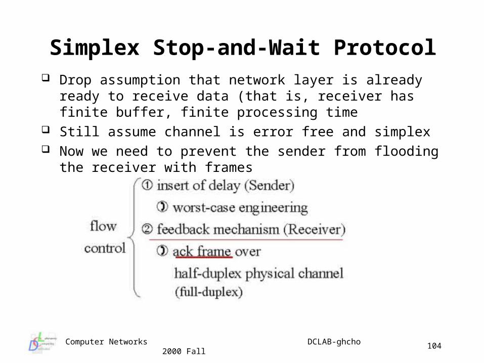
Simplex Stop-and-Wait Protocol Drop assumption that network layer is already ready to receive
data (that is, receiver has finite buffer, finite processing time Still assume channel is error free and simplex Now we need to prevent the sender from flooding the receiver
with frames
Computer Networks DCLAB-ghcho 2000 Fall
105
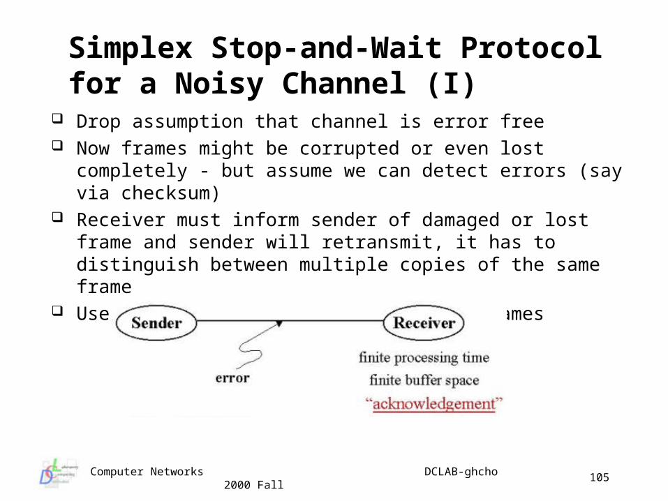
Simplex Stop-and-Wait Protocol for a Noisy Channel (I)
Drop assumption that channel is error free Now frames might be corrupted or even lost completely - but
assume we can detect errors (say via checksum) Receiver must inform sender of damaged or lost frame and
sender will retransmit, it has to distinguish between multiple copies of the same frame
Use a Sequence number to distinguish frames
Computer Networks DCLAB-ghcho 2000 Fall
106
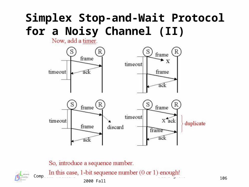
Simplex Stop-and-Wait Protocol for a Noisy Channel (II)
Computer Networks DCLAB-ghcho 2000 Fall
107
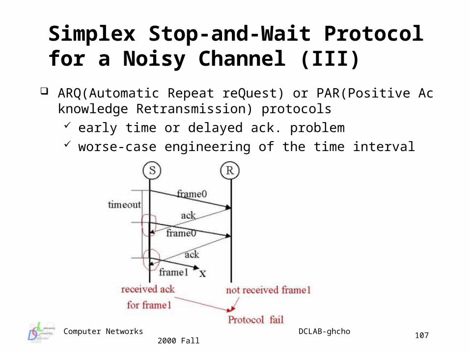
Simplex Stop-and-Wait Protocol for a Noisy Channel (III)
ARQ(Automatic Repeat reQuest) or PAR(Positive Acknowledge Retransmission) protocols early time or delayed ack. problem worse-case engineering of the time interval
Computer Networks DCLAB-ghcho 2000 Fall
108
Simplex Stop-and-Wait Protocol for a Noisy Channel (IV)
Full duplex data transmission considerations two physical circuits, each one for simplex data traffic
• bandwidth waste (one circuit) one physical circuit, interleaving data and ack. frames
• the type field in the header of the frames piggybacking (ack. field in the frame header)
• reduce the # of frame types as small as possible• advantages
– bandwidth improvement– processing time improvement– buffer space improvement
• disadvantages– heavy dependent of the availability of frames to be tra
nsmitted by the receive
Computer Networks DCLAB-ghcho 2000 Fall
109
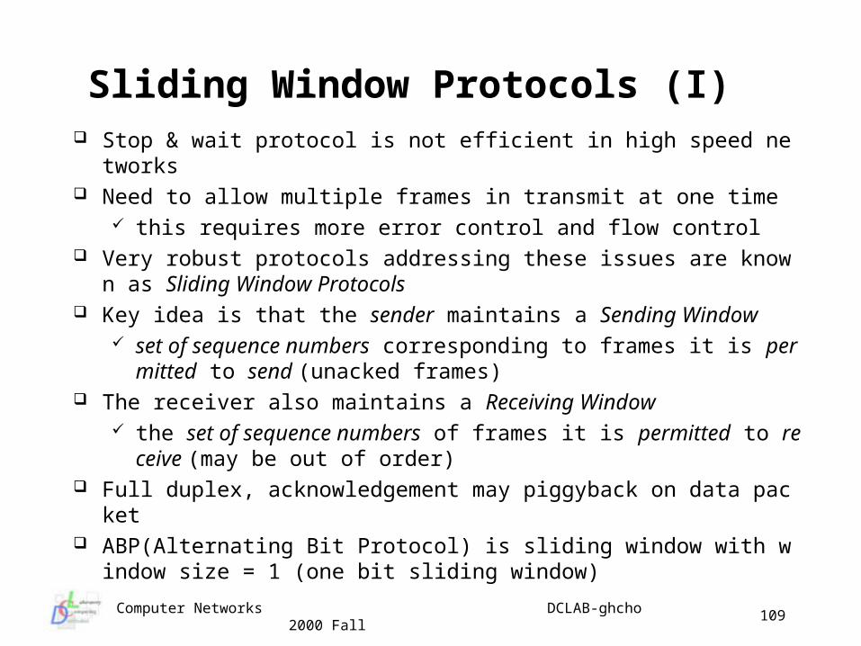
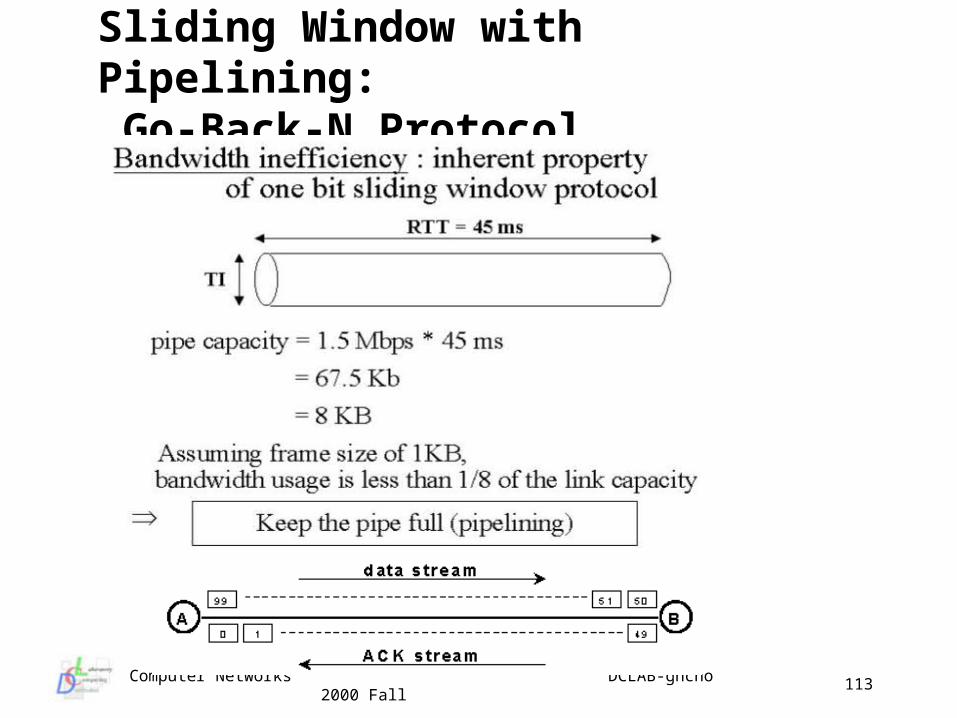
Sliding Window Protocols (I) Stop & wait protocol is not efficient in high speed networks Need to allow multiple frames in transmit at one time
this requires more error control and flow control Very robust protocols addressing these issues are known as Slidi
ng Window Protocols Key idea is that the sender maintains a Sending Window
set of sequence numbers corresponding to frames it is permitted to send (unacked frames)
The receiver also maintains a Receiving Window the set of sequence numbers of frames it is permitted to recei
ve (may be out of order) Full duplex, acknowledgement may piggyback on data packet ABP(Alternating Bit Protocol) is sliding window with window size
= 1 (one bit sliding window)
Computer Networks DCLAB-ghcho 2000 Fall
110
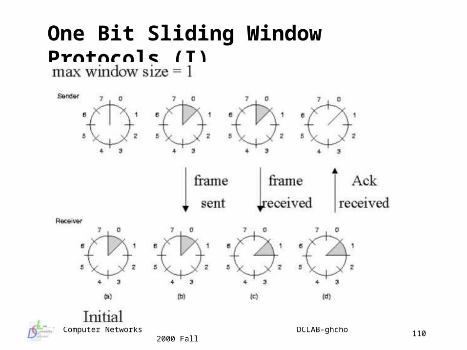
One Bit Sliding Window Protocols (I)
Computer Networks DCLAB-ghcho 2000 Fall
111
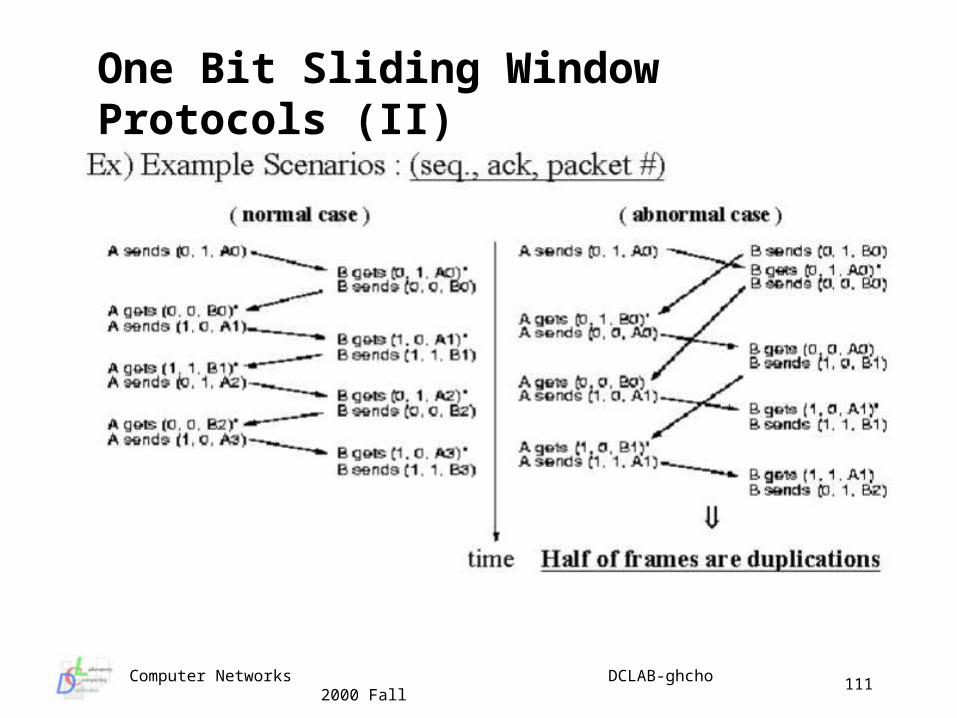
One Bit Sliding Window Protocols (II)
Computer Networks DCLAB-ghcho 2000 Fall
112
Sliding Window Protocols (II) Two windows can be different sizes, may change size Sequence numbers represent frames sent for which an ack. has
not been received sender buffers the frames whose sequence # are still in the w
indow for possible retransmission New packets handed down by the NL are given the next highest
sequence # and the upper edge of the window advanced when an ack. is received from the physical layer the lower ed
ge of the window is advanced If the window reaches maximum size N the DL refuses to accept
packets from the NL until an ack. arrives and a buffer is freed if a frame is received with the sequence # equal to the lower
bound of the window it is processed, the data passed to the NL, an ack. is generated and the window is rotated by one
Computer Networks DCLAB-ghcho 2000 Fall
113
Sliding Window with Pipelining: Go-Back-N Protocol
Computer Networks DCLAB-ghcho 2000 Fall
114
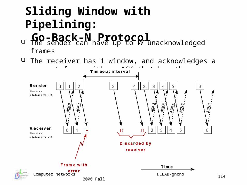
The sender can have up to W unacknowledged frames The receiver has 1 window, and acknowledges a correct frame
with an ACK that has the same number as the frame
Sliding Window with Pipelining: Go-Back-N Protocol
Computer Networks DCLAB-ghcho 2000 Fall
115
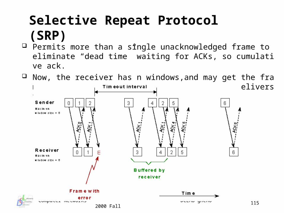
Permits more than a single unacknowledged frame to eliminate “dead time” waiting for ACKs, so cumulative ack.
Now, the receiver has n windows,and may get the frames in the wrong order from the PL, but it delivers the frames to the NL in order
Selective Repeat Protocol (SRP)
Computer Networks DCLAB-ghcho 2000 Fall
116
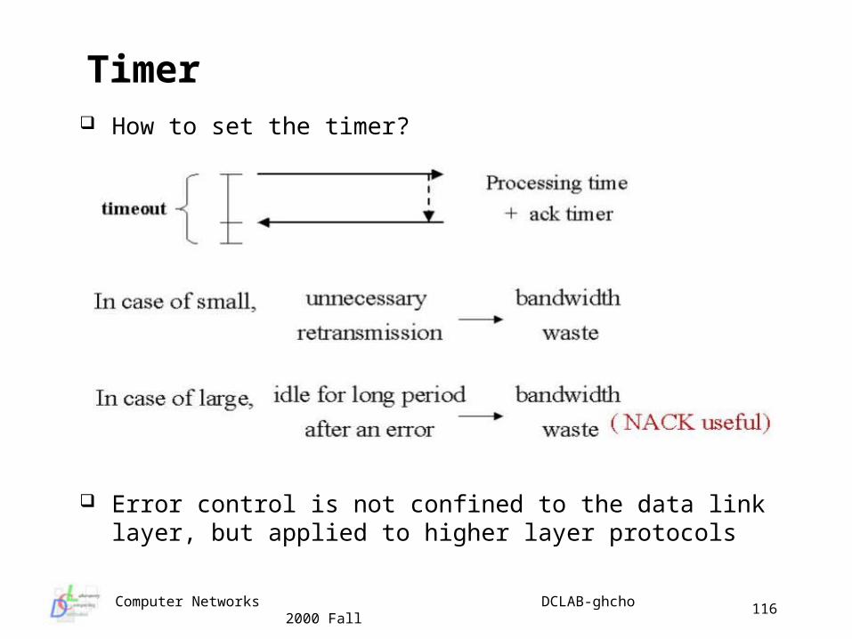
How to set the timer?
Error control is not confined to the data link layer, but applied to higher layer protocols
Timer
Computer Networks DCLAB-ghcho 2000 Fall
117
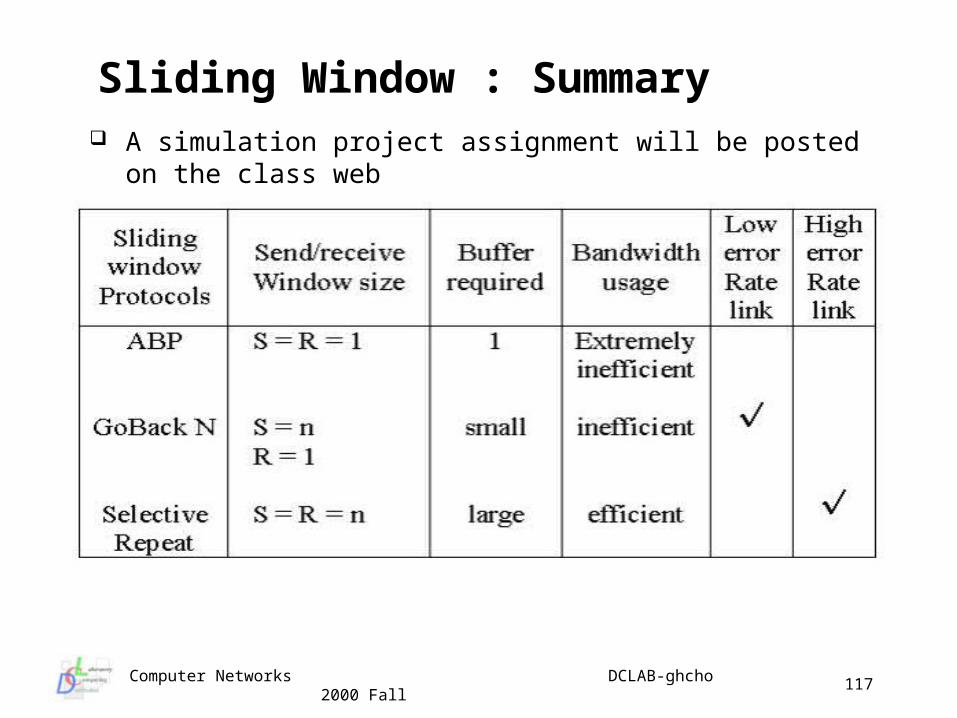
A simulation project assignment will be posted on the class web
Sliding Window : Summary
Computer Networks DCLAB-ghcho 2000 Fall
118
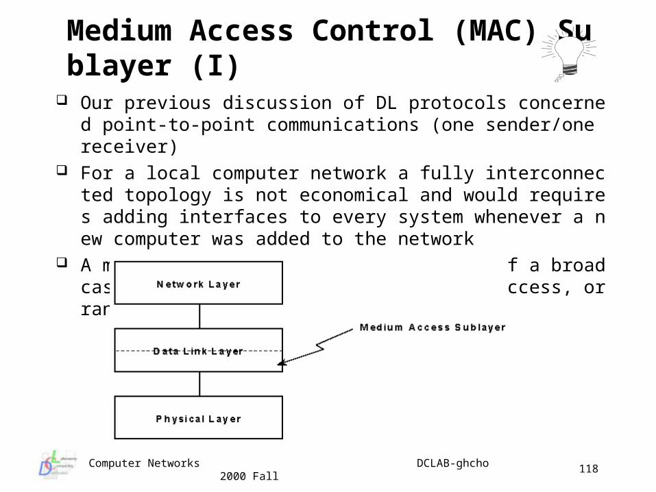
Our previous discussion of DL protocols concerned point-to-point communications (one sender/one receiver)
For a local computer network a fully interconnected topology is not economical and would requires adding interfaces to every system whenever a new computer was added to the network
A more economical approach is the use of a broadcast network with shared media : multiaccess, or random access channels
Medium Access Control (MAC) Sublayer (I)
Computer Networks DCLAB-ghcho 2000 Fall
119
Static channel allocation FDM (Frequency Division Multiplexing)
• only a small and fixed number of users• problem with fixed engineering, assume n channel
users n blocking even if bandwidth is wastedusers n bandwidth waste inherently
• computer comm. traffic is burst peak/mean = 1000/1 TDM (Time Division Multiplexing)
Dynamic channel allocation the network has some number N of independent stations
generating frames at a rate (usually assumed to Poisson) probability a station generates a frame in interval t is given by
t a single channel is shared by all stations (physical peers) stations detect a collision if more than one frame transmission
overlaps
Medium Access Control (MAC) Sublayer (II)
Computer Networks DCLAB-ghcho 2000 Fall
120
Goal : let users transmit whenever they have something to send
Procedure
1. transmit whenever you have data to send
2. listen to the broadcast : the sending host can always find out if its packet was destroyed just by listening to the downward broadcast one round-trip time later
3. if the packet was destroyed, wait a random amount of time and send it again
Note that if the first bit of a new packet overlaps with the last bit of a packet almost finished, both packets are totally destroyed
Due to the collisions and idle periods, pure ALOHA is limited to approximately 18% throughput in the nest case
Can we improve this
Pure ALOHA
Computer Networks DCLAB-ghcho 2000 Fall
121
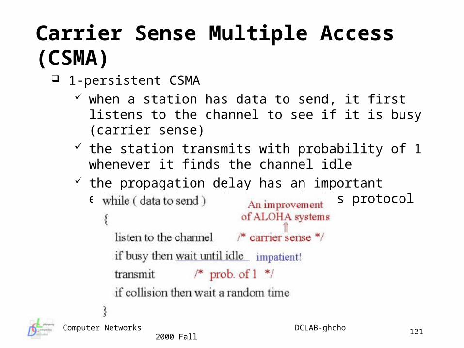
1-persistent CSMA when a station has data to send, it first listens to the
channel to see if it is busy (carrier sense) the station transmits with probability of 1 whenever it finds
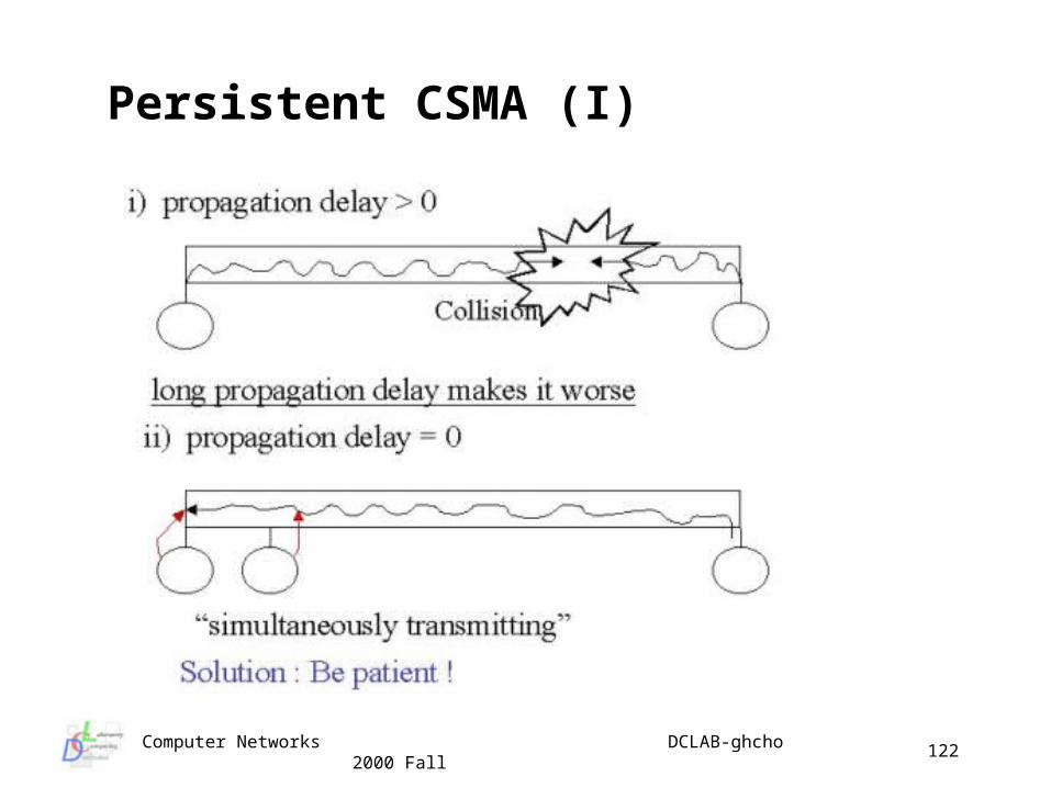
the channel idle the propagation delay has an important effect on the
performance of this protocol
Carrier Sense Multiple Access (CSMA)
Computer Networks DCLAB-ghcho 2000 Fall
122
Persistent CSMA (I)
Computer Networks DCLAB-ghcho 2000 Fall
123
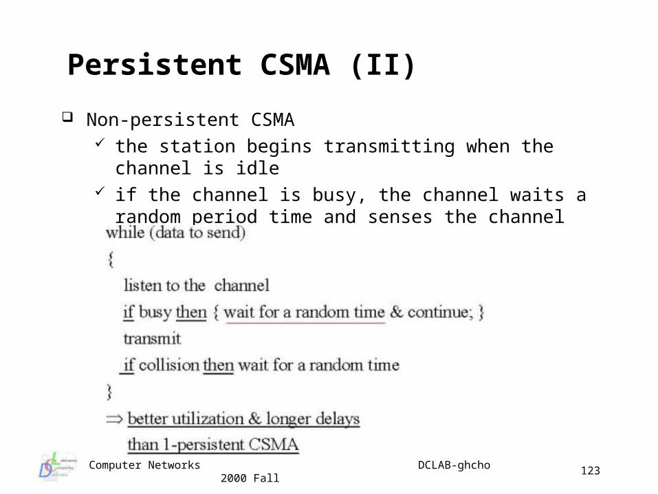
Non-persistent CSMA the station begins transmitting when the channel is idle if the channel is busy, the channel waits a random period
time and senses the channel again
Persistent CSMA (II)
Computer Networks DCLAB-ghcho 2000 Fall
124
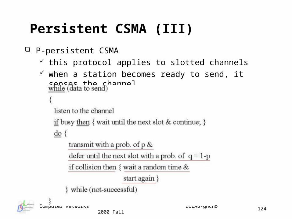
P-persistent CSMA this protocol applies to slotted channels when a station becomes ready to send, it senses the channel
Persistent CSMA (III)
Computer Networks DCLAB-ghcho 2000 Fall
125
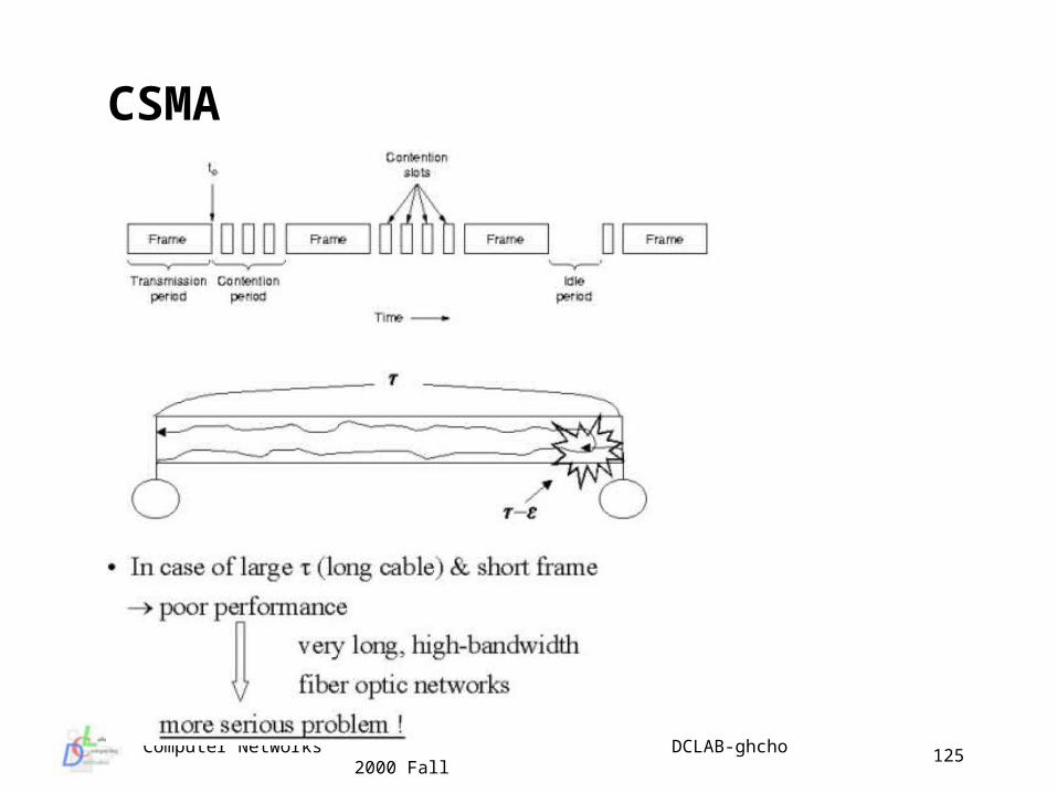
CSMA
Computer Networks DCLAB-ghcho 2000 Fall
126
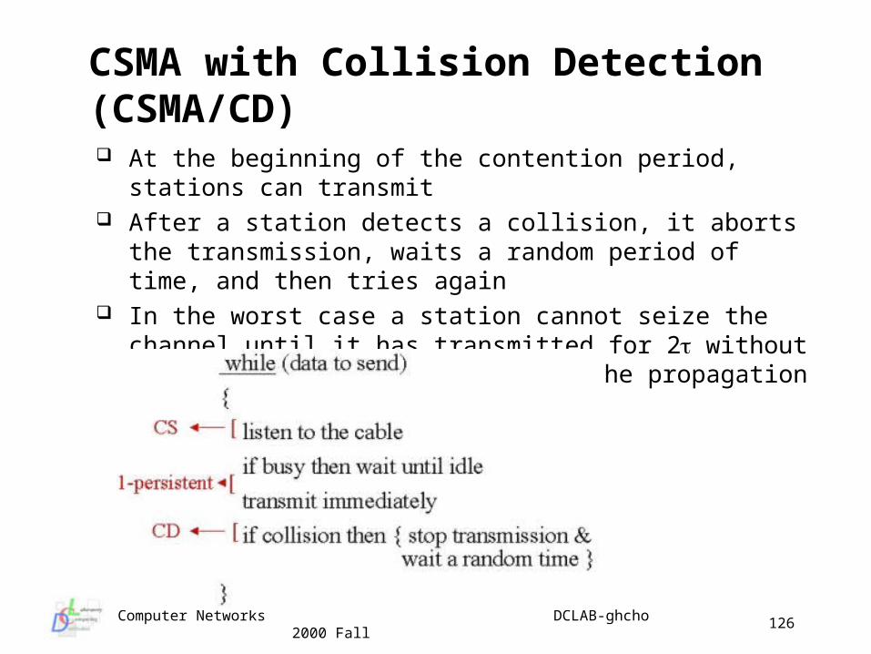
At the beginning of the contention period, stations can transmit After a station detects a collision, it aborts the transmission,
waits a random period of time, and then tries again In the worst case a station cannot seize the channel until it has
transmitted for 2 without hearing a collision, where is the propagation delay from end to end
CSMA with Collision Detection (CSMA/CD)
Computer Networks DCLAB-ghcho 2000 Fall
127
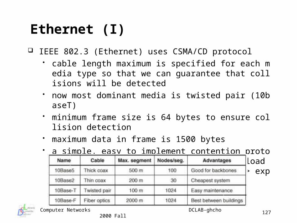
IEEE 802.3 (Ethernet) uses CSMA/CD protocol cable length maximum is specified for each media type so t
hat we can guarantee that collisions will be detected now most dominant media is twisted pair (10baseT) minimum frame size is 64 bytes to ensure collision detectio
n maximum data in frame is 1500 bytes a simple, easy to implement contention protocol - utilization
decreases as offered load increases - low delay characteristics => exponential backoff
Ethernet (I)
Computer Networks DCLAB-ghcho 2000 Fall
128
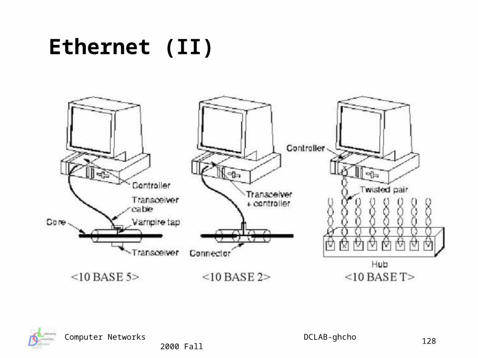
Ethernet (II)
Computer Networks DCLAB-ghcho 2000 Fall
129
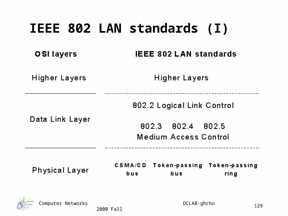
IEEE 802 LAN standards (I)
Computer Networks DCLAB-ghcho 2000 Fall
130
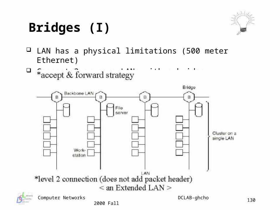
LAN has a physical limitations (500 meter Ethernet) Connect 2 or more LANs with a bridge
Bridges (I)
Computer Networks DCLAB-ghcho 2000 Fall
131
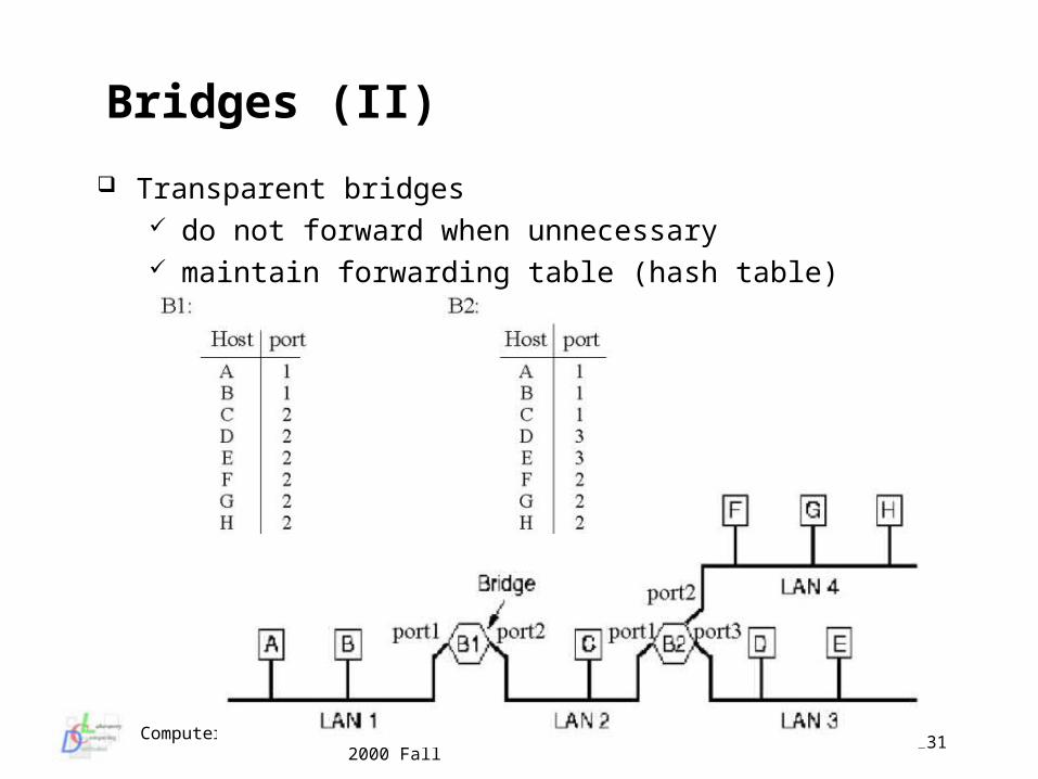
Transparent bridges do not forward when unnecessary maintain forwarding table (hash table)
Bridges (II)
Computer Networks DCLAB-ghcho 2000 Fall
132
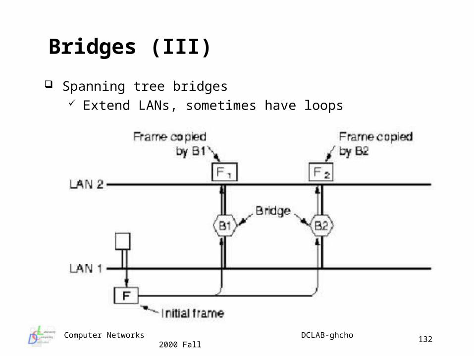
Spanning tree bridges Extend LANs, sometimes have loops
Bridges (III)
Computer Networks DCLAB-ghcho 2000 Fall
133
Limitations of bridges do not scale
• broadcasting does not scale• spanning tree algorithm does not scale
do not accommodate heterogeneity• same format for address in network’s frame header
beware of transparency• bridge congestion• latency is higher and variable• frame ordering
Bridges (IV)
Computer Networks DCLAB-ghcho 2000 Fall
134
Lecture Topic 4
Network Layer
Routing algorithms Congestion control algorithms InterNetworking issues IP (Internet Protocol) Internet routing IPv6 protocol
Computer Networks DCLAB-ghcho 2000 Fall
135
The Network layer (OSI layer 3)
The Network layer is responsible for communication all the way from source to destination, that is addressing and routing three host identifiers
names : what object is (a location independent characteristic of a network entity)
addresses : where it is (a function of the location of the destination)
routes : how to get there (something that depends on both the source and destination)
Routing may include multiple hops through intermediate systems and include crossing several different networks
It also may be concerned with congestion and optimization of the subnet
Computer Networks DCLAB-ghcho 2000 Fall
136
Classes of Routing Algorithms
Adaptive Algorithms collect information dynamically from other routers (IS’s) either lo
cally or globally adjust to changes in network topology adjust to changes in network traffic load differ in metrics used and frequency of information gathering
Non-Adaptive Algorithms often called static routing predetermined routing policies programmed into router (IS) does not adjust to changes in network topology does not adjust to changes in network traffic
Computer Networks DCLAB-ghcho 2000 Fall
137
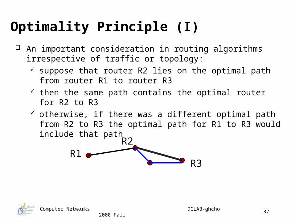
Optimality Principle (I)
An important consideration in routing algorithms irrespective of traffic or topology: suppose that router R2 lies on the optimal path from router R1 to
router R3 then the same path contains the optimal router for R2 to R3 otherwise, if there was a different optimal path from R2 to R3 the
optimal path for R1 to R3 would include that path
R1R3
R2
Computer Networks DCLAB-ghcho 2000 Fall
138
C
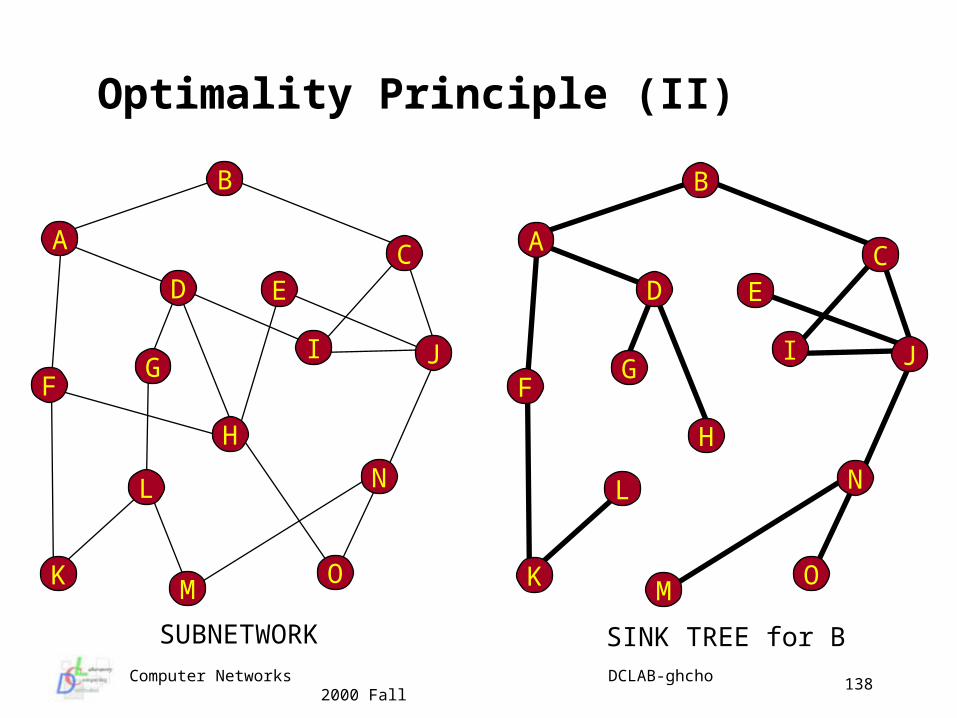
Optimality Principle (II)
B
A
D E
I J
K
N
OM
L
H
GF
C
B
A
D E
I J
K
N
OM
L
H
GF
SUBNETWORK SINK TREE for B
Computer Networks DCLAB-ghcho 2000 Fall
139
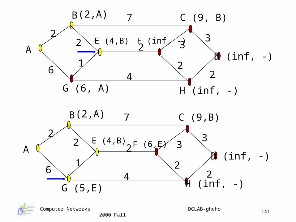
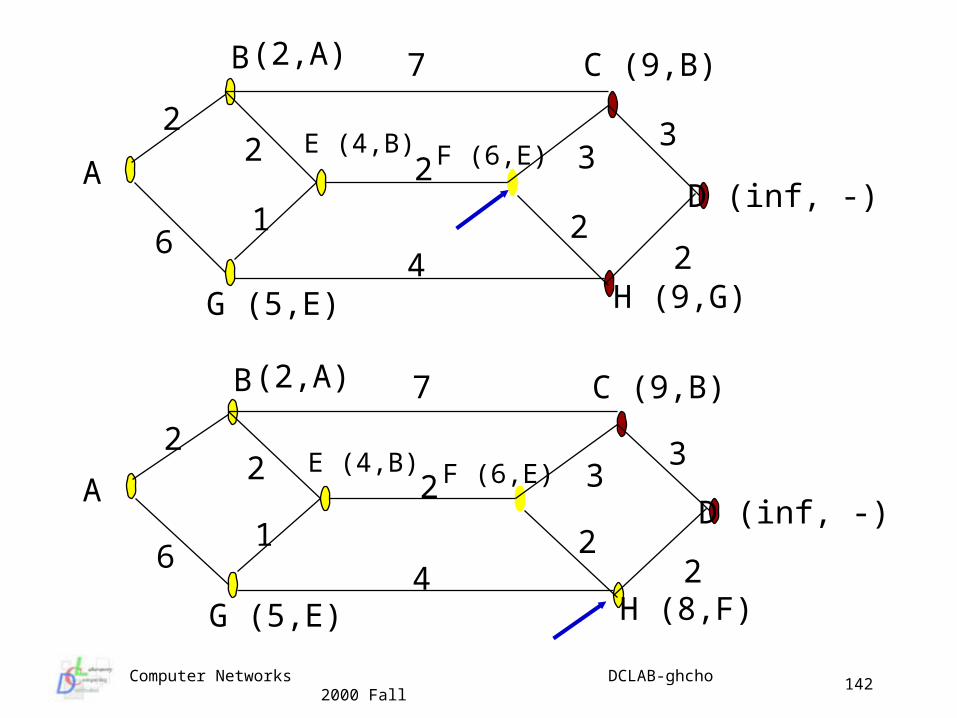
Static Routing Algorithms : Shortest Path Shortest path
simple and widely used have to determine the metric used to define “shortest” - may be n
umber of hops, or could be queuing delay or some cost generally “path length” will be a function of a variety of measures -
cost, bandwidth, traffic, delay, etc. with appropriate weighting of each component
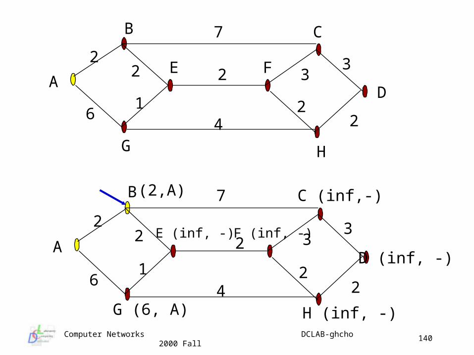
Dijkstra’s algorithm each node is labeled with its best path from source initially all labels are tentative and assigned large values (infinity) algorithm proceeds to find best paths node labels are changed to reflect better paths and made perma
nent when the shortest path from the source is determined permanent labels can not change once assigned
Computer Networks DCLAB-ghcho 2000 Fall
140
A
B
D
22
1
2
7
33
22
H
46
G
E F
C
A
B
D (inf, -)
22
1
2
7
33
22
H (inf, -)
46
G (6, A)
E (inf, -) F (inf, -)
C (inf,-)(2,A)
Computer Networks DCLAB-ghcho 2000 Fall
141
A
B
D (inf, -)
22
1
2
7
33
22
H (inf, -)4
6
G (6, A)
E (4,B) F (inf, -)
C (9, B)(2,A)
A
B
D (inf, -)
22
1
2
7
33
224
6
G (5,E)
E (4,B) F (6,E)
C (9,B)(2,A)
H (inf, -)
Computer Networks DCLAB-ghcho 2000 Fall
142
A
B
D (inf, -)
22
1
2
7
33
224
6
G (5,E)
E (4,B) F (6,E)
C (9,B)(2,A)
H (9,G)
A
B
D (inf, -)
22
1
2
7
33
224
6
G (5,E)
E (4,B) F (6,E)
C (9,B)(2,A)
H (8,F)
Computer Networks DCLAB-ghcho 2000 Fall
143
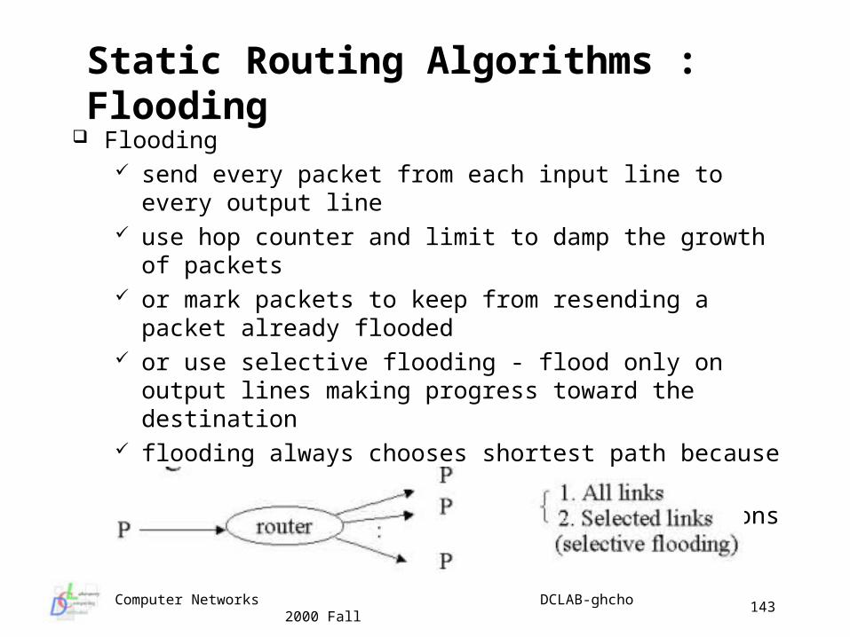
Static Routing Algorithms : Flooding Flooding
send every packet from each input line to every output line use hop counter and limit to damp the growth of packets or mark packets to keep from resending a packet already
flooded or use selective flooding - flood only on output lines making
progress toward the destination flooding always chooses shortest path because it tries every
path simultaneously! used as benchmark or in military applications
Computer Networks DCLAB-ghcho 2000 Fall
144
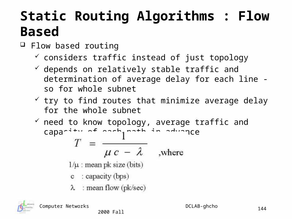
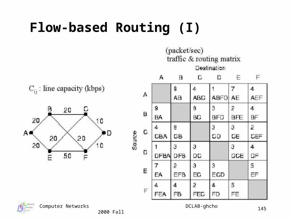
Static Routing Algorithms : Flow Based
Flow based routing considers traffic instead of just topology depends on relatively stable traffic and determination of
average delay for each line - so for whole subnet try to find routes that minimize average delay for the whole
subnet need to know topology, average traffic and capacity of each
path in advance
Computer Networks DCLAB-ghcho 2000 Fall
145
Flow-based Routing (I)
Computer Networks DCLAB-ghcho 2000 Fall
146
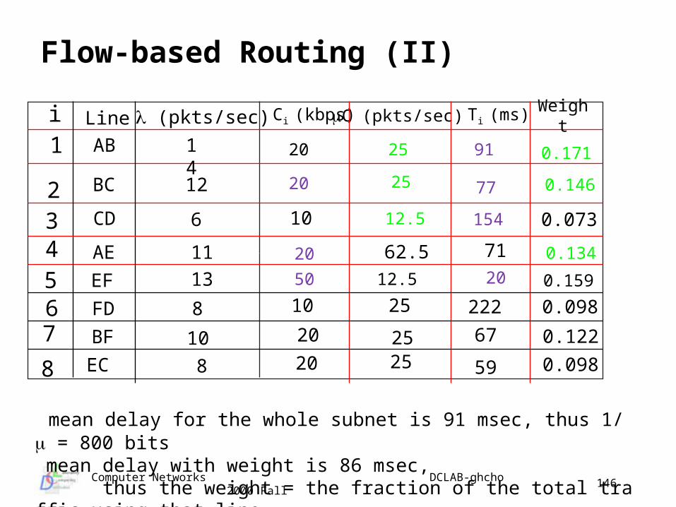
Flow-based Routing (II)
20
20
20
50
Ci (kbps) C (pkts/sec) Ti (ms) Weight
25
25
12.5
12.5
91
77
154
20
0.171
0.146
0.134
0.159
i
1
234
Line (pkts/sec)
5
76
8
AB
BC
CD
AE
EF
FD
BF
EC
14
12
6
11
13
8
10
8
10
10
20
20
62.5
25
2525
71
222
67
59
0.073
0.098
0.122
0.098
mean delay for the whole subnet is 91 msec, thus 1/ = 800 bits mean delay with weight is 86 msec,
thus the weight = the fraction of the total traffic using that line
Computer Networks DCLAB-ghcho 2000 Fall
147
Dynamic Routing Algorithms : Distance Vector
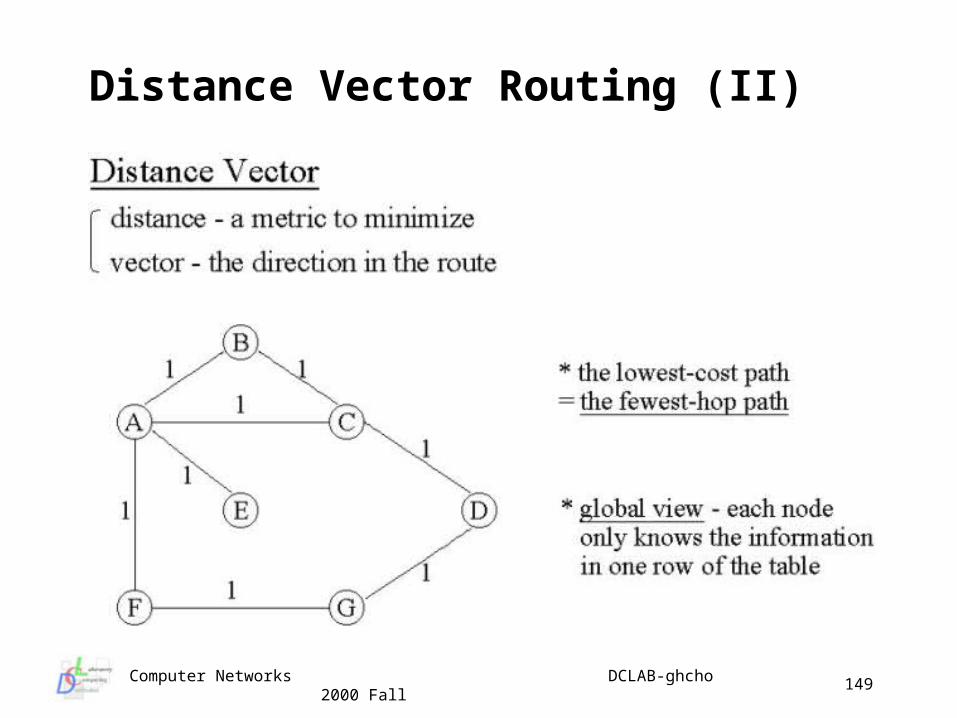
Distance vector routing (Bellman-Ford, Ford-Fulkerson) one of the most commonly used types of algorithms (original AR
PANET, Internet RIP, BGP) each router maintains a vector giving the best know distance to
a destination and which output line to use vectors are kept in tables updated by exchanging information wi
th neighboring routers table gives preferred outgoing line and estimate of distance for
each destination router the distance metric might be number of hops, time delay in millis
econds, total number of packet queued along the path … a router assumed to know the metric of its neighbors can suffer from slow propagation of information about routes tha
t have gone down
Computer Networks DCLAB-ghcho 2000 Fall
148
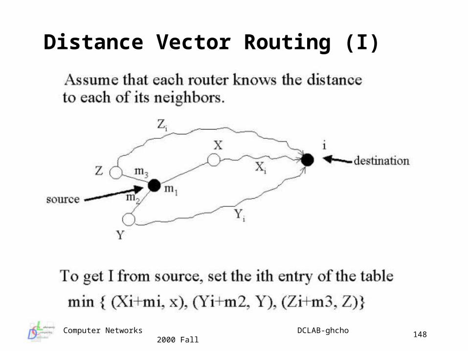
Distance Vector Routing (I)
Computer Networks DCLAB-ghcho 2000 Fall
149
Distance Vector Routing (II)
Computer Networks DCLAB-ghcho 2000 Fall
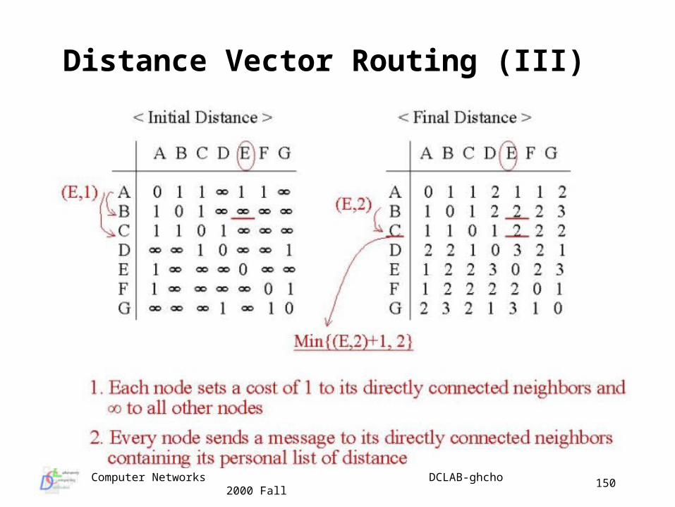
150
Distance Vector Routing (III)
Computer Networks DCLAB-ghcho 2000 Fall
151
Distance Vector Routing (IV)
A B C D
E F GH
IJ K L
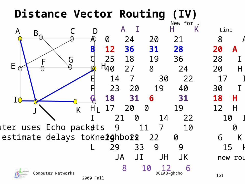
A 0 24 20 21 8 AB 12 36 31 28 20 AC 25 18 19 36 28 ID 40 27 8 24 20 HE 14 7 30 22 17 IF 23 20 19 40 30 IG 18 31 6 31 18 HH 17 20 0 19 12 H I 21 0 14 22 10 IJ 9 11 7 10 0 -K 24 22 22 0 6 KL 29 33 9 9 15 k JA JI JH JK new routing
8 10 12 6
A I H K
Router uses Echo packetsto estimate delays to neighbors
New for J Line
Computer Networks DCLAB-ghcho 2000 Fall
152
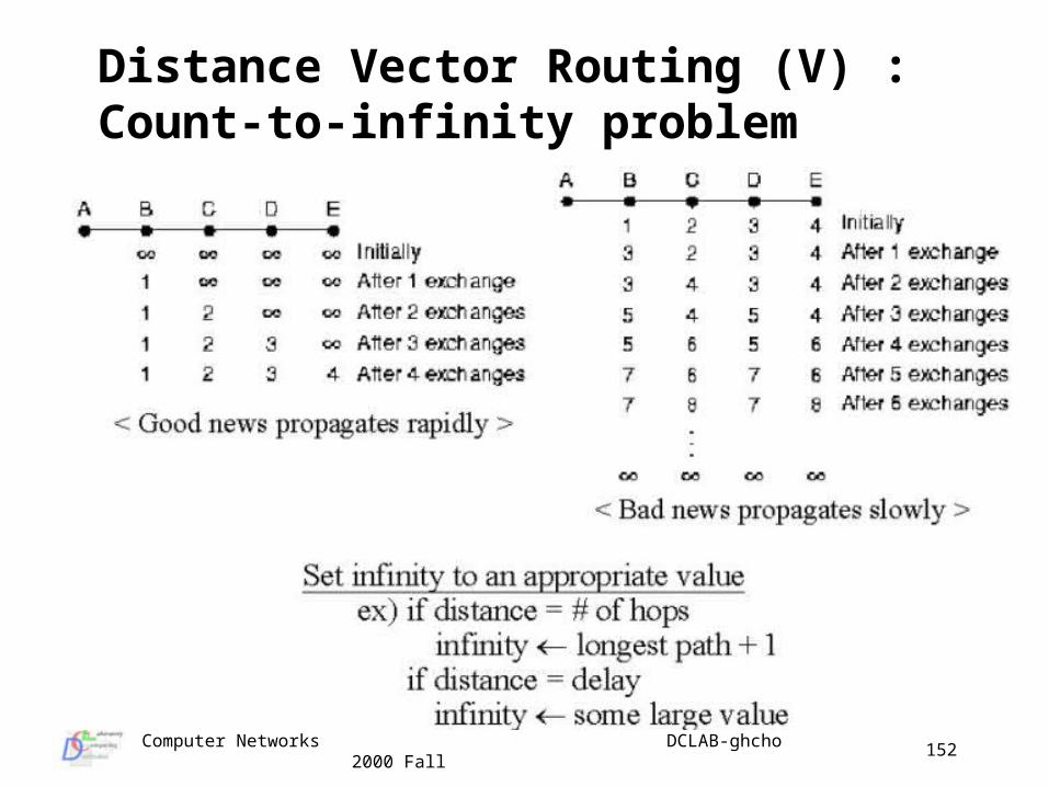
Distance Vector Routing (V) : Count-to-infinity problem
Computer Networks DCLAB-ghcho 2000 Fall
153
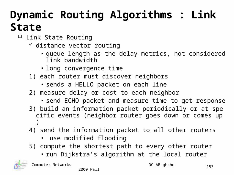
Dynamic Routing Algorithms : Link State Link State Routing
distance vector routing • queue length as the delay metrics, not considered link bandwi
dth• long convergence time
1) each router must discover neighbors• sends a HELLO packet on each line
2) measure delay or cost to each neighbor• send ECHO packet and measure time to get response
3) build an information packet periodically or at specific events (neighbor router goes down or comes up)
4) send the information packet to all other routers• use modified flooding
5) compute the shortest path to every other router• run Dijkstra’s algorithm at the local router
Computer Networks DCLAB-ghcho 2000 Fall
154
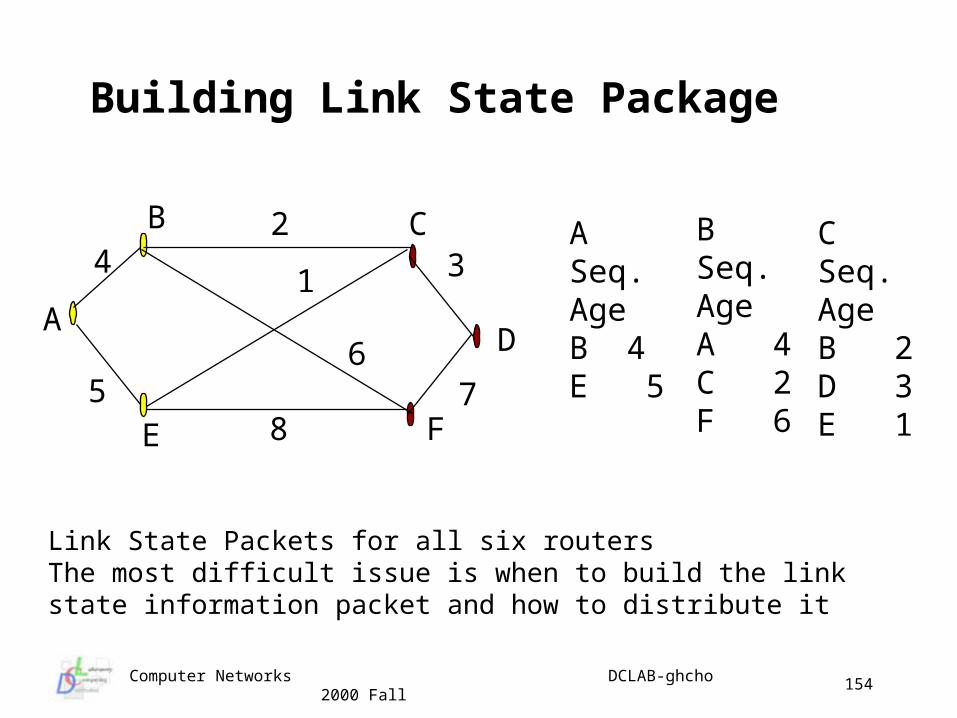
Building Link State Package
A
B
D
42
75E
C
F
31
6
8
ASeq.AgeB 4E 5
BSeq.AgeA 4C 2F 6
CSeq.AgeB 2D 3E 1
Link State Packets for all six routersThe most difficult issue is when to build the linkstate information packet and how to distribute it
Computer Networks DCLAB-ghcho 2000 Fall
155
Distributing the Link State Packets
Use flooding to distribute link state packets Each packet contains a sequence number that is incremented for ea
ch new packet generated by the router Routers keep track of all pairs (source, seq.) they see It checks the incoming link state packets
if new, it is forwarded on all lines except the one it came on if not new, (duplicate), it is discarded
Once a router has a full set of link state packets, the entire subnet graph can be constructed
Dijkstra’s Algorithm can be run locally to construct the shortest path for n routers and each with k neighbors
• we need memory proportional to kn
Computer Networks DCLAB-ghcho 2000 Fall
156
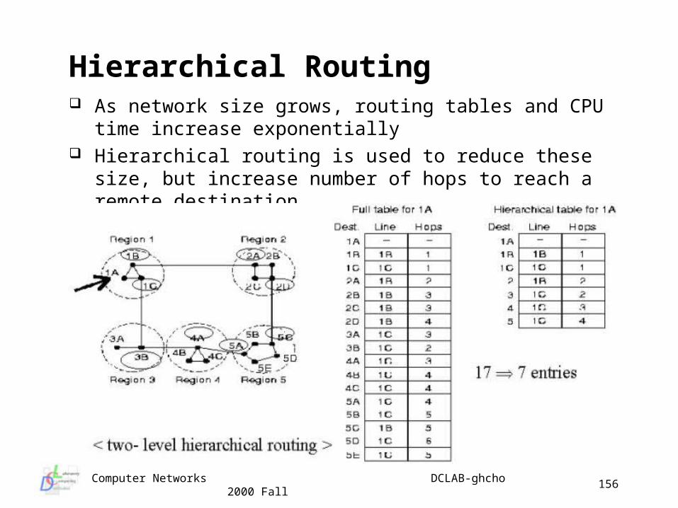
Hierarchical Routing As network size grows, routing tables and CPU time increase
exponentially Hierarchical routing is used to reduce these size, but increase
number of hops to reach a remote destination
Computer Networks DCLAB-ghcho 2000 Fall
157
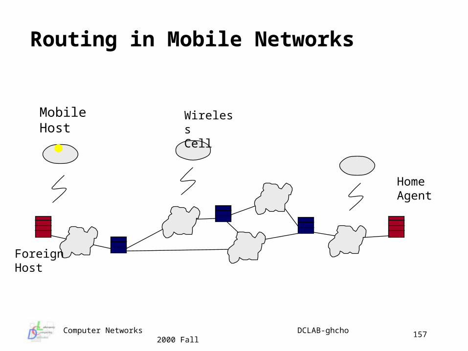
MobileHost
ForeignHost
HomeAgent
WirelessCell
Routing in Mobile Networks
Computer Networks DCLAB-ghcho 2000 Fall
158
Routing for Mobile Hosts
All users assumed to have home location that never changes (Home Agent)
Foreign agents broadcast information packets mobile host registers with foreign agent foreign agent contacts home agent that replies with ack. After pro
per authentication, security Once ack is received, the mobile user is registered Mobile hosts de-register once they leave the area
Computer Networks DCLAB-ghcho 2000 Fall
159
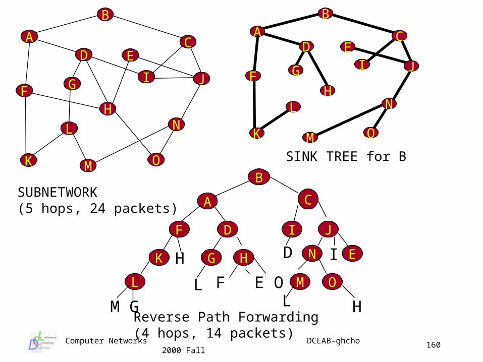
Broadcast Routing
Broadcast by repetitive sending the message for each destination flooding might be an interesting approach to perform
broadcasting multi-destination routing
• each packet has a list of destinations or a bit map for desired destinations
• router generates a new copy for each output line to be used to reach the desired destinations
– partition the destinations among the output lines and eventually the node will receive only one destination
sink tree or spanning tree Broadcast incoming packets only on the spanning tree lines
makes excellent use of bandwidth problem is that each router must have knowledge of some
spanning tree
Computer Networks DCLAB-ghcho 2000 Fall
160
C
B
AD E
I J
K
N
OM
L
H
GF
SUBNETWORK(5 hops, 24 packets)
C
B
A
Reverse Path Forwarding(4 hops, 14 packets)
C
BA
D EI J
K
N
OM
LH
GF
SINK TREE for B
F
HG NK
I JD
H D
L M O
I
L F E O
M G L H
E
Computer Networks DCLAB-ghcho 2000 Fall
161
C
B
A
D E
I J
K
N
OM
L
H
GF
SINK TREE for B
1,2
1
1
2
2 1
C
B
A
I
SINK TREE for B
1
C
B
A
J
K
F
1
11
22
2
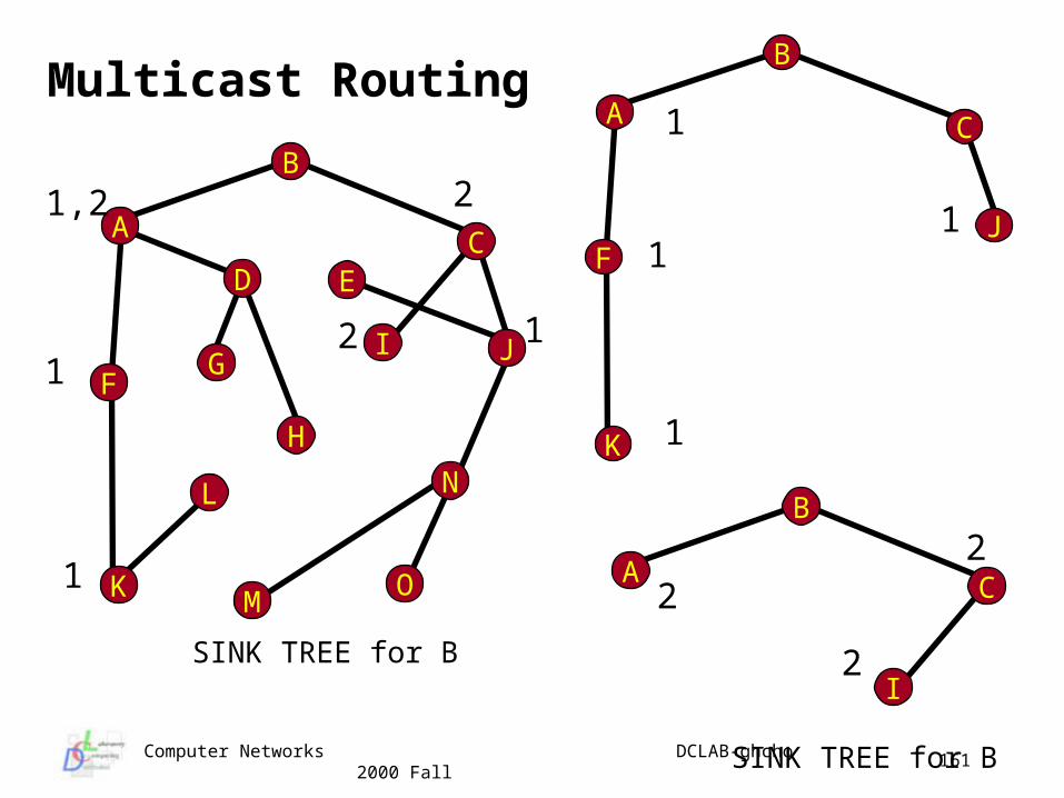
Multicast Routing
Computer Networks DCLAB-ghcho 2000 Fall
162
Congestion Control (I)
If packet traffic becomes too heavy routers can begin to loose packets
It an arise because of sudden burst of incoming traffic on several lines all destined for same output line
Processors in some routers might be slow Some lines may have lower bandwidth Congestion tends to generate more congestion as packet time
-outs expire and packets are retransmitted, buffers become locked waiting for ack’s, etc.
Congestion control is a global issue in the network (vs. flow control which is a point-to-point issue between a sender and receiver)
Computer Networks DCLAB-ghcho 2000 Fall
163
Congestion Control (II)
Computer Networks DCLAB-ghcho 2000 Fall
164
Congestion Control (III)
Computer Networks DCLAB-ghcho 2000 Fall
165
General Principles of Congestion Control
We can take closed loop or open loop viewpoint for open loop control
• decide when to accept new traffic• decide when to discard packets• decide which packets to discard• make decisions independent of current state
for closed loop control• based on feedback loop concept• actively monitor network to detect congestion• pass information to systems where action is needed• adjust network operation to correct the congestion
Computer Networks DCLAB-ghcho 2000 Fall
166
Open Loop Systems
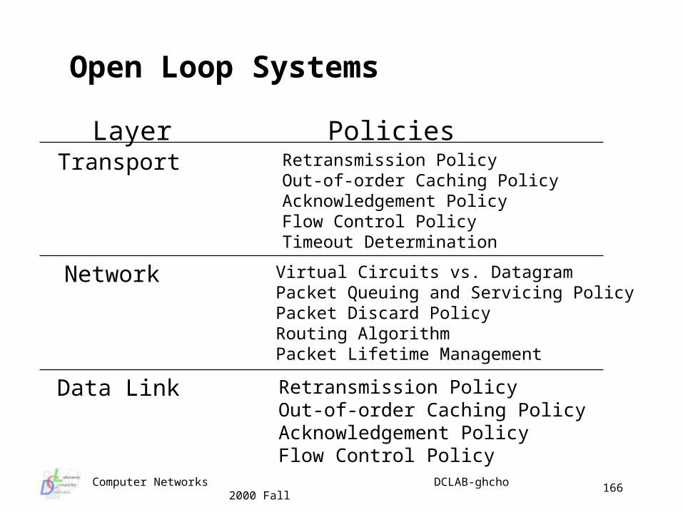
Layer PoliciesTransport
Network
Data Link
Retransmission PolicyOut-of-order Caching PolicyAcknowledgement PolicyFlow Control PolicyTimeout Determination
Virtual Circuits vs. DatagramPacket Queuing and Servicing PolicyPacket Discard PolicyRouting AlgorithmPacket Lifetime Management
Retransmission PolicyOut-of-order Caching PolicyAcknowledgement PolicyFlow Control Policy
Computer Networks DCLAB-ghcho 2000 Fall
167
Closed Loop Control
We need metrics to monitor for congestion percentage of packets discarded due to buffer space queue lengths number of retransmissions packet delay measures
When congestion is detected may send control packets to traffic sources
• may add to the congestion May use bits in existing packet headers of control packets
Dynamically query other routers about potential congestion before it occurs
Problem is to get time scale correct to keep from oscillating
Computer Networks DCLAB-ghcho 2000 Fall
168
DL Policies Impact on Congestion
Retransmission Policy affects how fast a times out waiting for an Ack and which packets are retransmitted on timeout short timeout and Go Back N => more load long timeout and Selective Repeat => less load
Caching Policy affects how receiver deals with packets received out of order caching out of order packets lightens network load => nee
d for buffer memory at receiver Ack Policy can affect congestion
piggybacking could result in extra timeouts and retransmissions
may also save on traffic Flow Control Policy (e.g. Window size) impacts offered load
large window size => higher load
Computer Networks DCLAB-ghcho 2000 Fall
169
NL Policies Impact on Congestion Choice of service strategy
virtual circuits may lead to congested links congestion control algorithms may not work with Datagram service
Packet queuing and service policy affects where congestion may occur maintain an input Q per line; maintain an output Q per line; or both? how are the queues serviced? are there priorities?
Packet discard policy affects how we determine which packets to drop in the router when there is congestion age, # of hops, some priority
Routing algorithm choice may evenly distribute or concentrate traffic possibly leading to congestion
Packet Lifetime concerns how long the packet can bounce around the net before being discarded too long => congestion as packets bounce around too short => senders time-out and retransmit
Computer Networks DCLAB-ghcho 2000 Fall
170
TL Policies Impact on Congestion
Recall TL is first end-to-end layer Peer transport entities talk across the internetwork So issues are basically the same as the DL where stations ar
e logically adjacent (point-to-point) Primary difference is that it is much more difficult to determine
timeout values across an internetworked environment than across a LAN
Short timeouts contribute to congestion by generating more packets while long timeouts impact response time when packets are lost
Computer Networks DCLAB-ghcho 2000 Fall
171
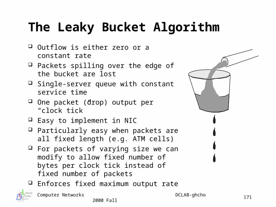
The Leaky Bucket Algorithm
Outflow is either zero or a constant rate Packets spilling over the edge of the
bucket are lost Single-server queue with constant
service time One packet (drop) output per “clock tick” Easy to implement in NIC Particularly easy when packets are all
fixed length (e.g. ATM cells) For packets of varying size we can
modify to allow fixed number of bytes per clock tick instead of fixed number of packets
Enforces fixed maximum output rate
Computer Networks DCLAB-ghcho 2000 Fall
172
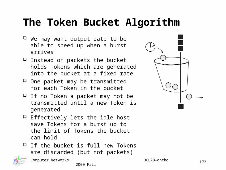
The Token Bucket Algorithm
We may want output rate to be able to speed up when a burst arrives
Instead of packets the bucket holds Tokens which are generated into the bucket at a fixed rate
One packet may be transmitted for each Token in the bucket
If no Token a packet may not be transmitted until a new Token is generated
Effectively lets the idle host save Tokens for a burst up to the limit of Tokens the bucket can hold
If the bucket is full new Tokens are discarded (but not packets)
Computer Networks DCLAB-ghcho 2000 Fall
173
Internetworking Issues
Expect that there will continue to be a large variety of protocols at each layer
Interconnecting heterogeneous networks will introduce many conflicts
To provide services we want Network layer to accommodate: different addressing schemes different maximum packet sizes different network access mechanisms …
Network layer may have to accommodate: different timeout values error recovery status reporting routing & congestion control user access control
Computer Networks DCLAB-ghcho 2000 Fall
174
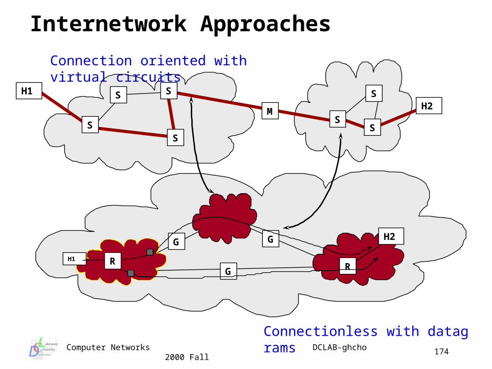
Internetwork Approaches
G G
G
H1 R
H2
R
Connectionless with datagrams
S
S
H1
S
S
Connection oriented with virtual circuits
MH2
SS
S
Computer Networks DCLAB-ghcho 2000 Fall
175
Connection Oriented Approach
Build virtual circuit pathway through the internetwork between the source and the destination
Switches maintain information about the virtual circuits The connection oriented approach is often more appropriate when the
internetwork is homogeneous Benefits of virtual circuit based internetworking include:
resource allocation at circuit setup sequencing is guaranteed low header overhead no duplicate packets
Drawbacks of internetworking based Virtual Circuit include: switch resources needed for each circuit switch failure brings down the whole connection certain paths may be susceptible to congestion difficult to incorporate non-VC based network into the internetwork
Computer Networks DCLAB-ghcho 2000 Fall
176
Connectionless Approach
For connectionless we route the packets through the network with routers performing a role similar to the switches but packets do not need to all follow the same route useful for heterogeneous networks
Gateways interconnect networks and are given differing names depending on the layer repeaters - physical layer bridges - DL/MAC layer routers (Gateways, Multiprotocol Routers) - Network Layer transport Gateways - Transport Layer application Gateways (e.g. email gateway) - Application Layer probably not useful at Presentation or Session layer
Computer Networks DCLAB-ghcho 2000 Fall
177
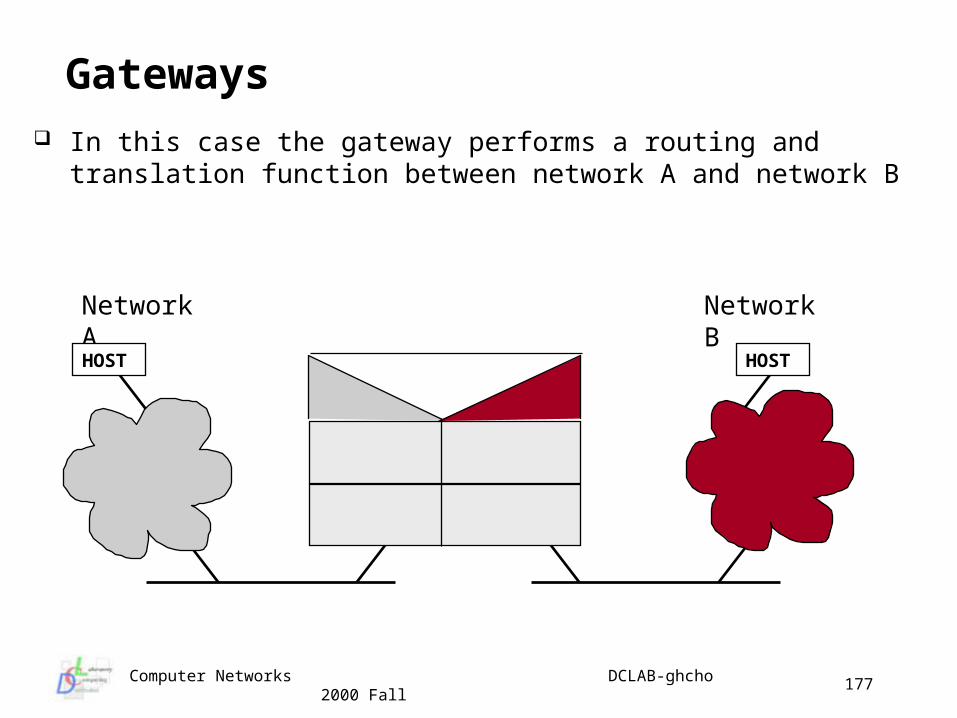
Gateways In this case the gateway performs a routing and translation function
between network A and network B
Network A Network B
HOST HOST
Computer Networks DCLAB-ghcho 2000 Fall
178
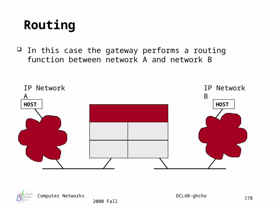
Routing
In this case the gateway performs a routing function between network A and network B
IP Network A IP Network B
HOST HOST
Computer Networks DCLAB-ghcho 2000 Fall
179
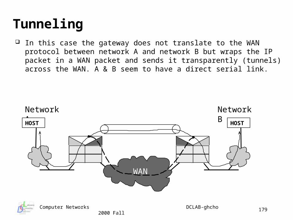
Tunneling In this case the gateway does not translate to the WAN protocol
between network A and network B but wraps the IP packet in a WAN packet and sends it transparently (tunnels) across the WAN. A & B seem to have a direct serial link.
Network A Network B
HOST HOST
WAN
Computer Networks DCLAB-ghcho 2000 Fall
180
Fragmentation If our data has to traverse many diverse networks it’s likely that they wi
ll have different maximum data “payload” sizes This may be determined by OS (device driver) parameters, physical or
data link layer hardware or optimization efforts Usually the size of PDU payload increases in higher layers (higher leve
ls of abstraction) Internetwork has to deal with differences - usually means we have to fr
agment larger packets Easy part - Gateway is allowed to break up a packet into fragments an
d send each fragment as a separate piece Hard part - Gateway has to put pieces back together to reconstruct the
original packet So the question is - do we need to put them back together again? As usual there are two competing viewpoints
transparent fragmentation non-transparent fragmentation
Computer Networks DCLAB-ghcho 2000 Fall
181
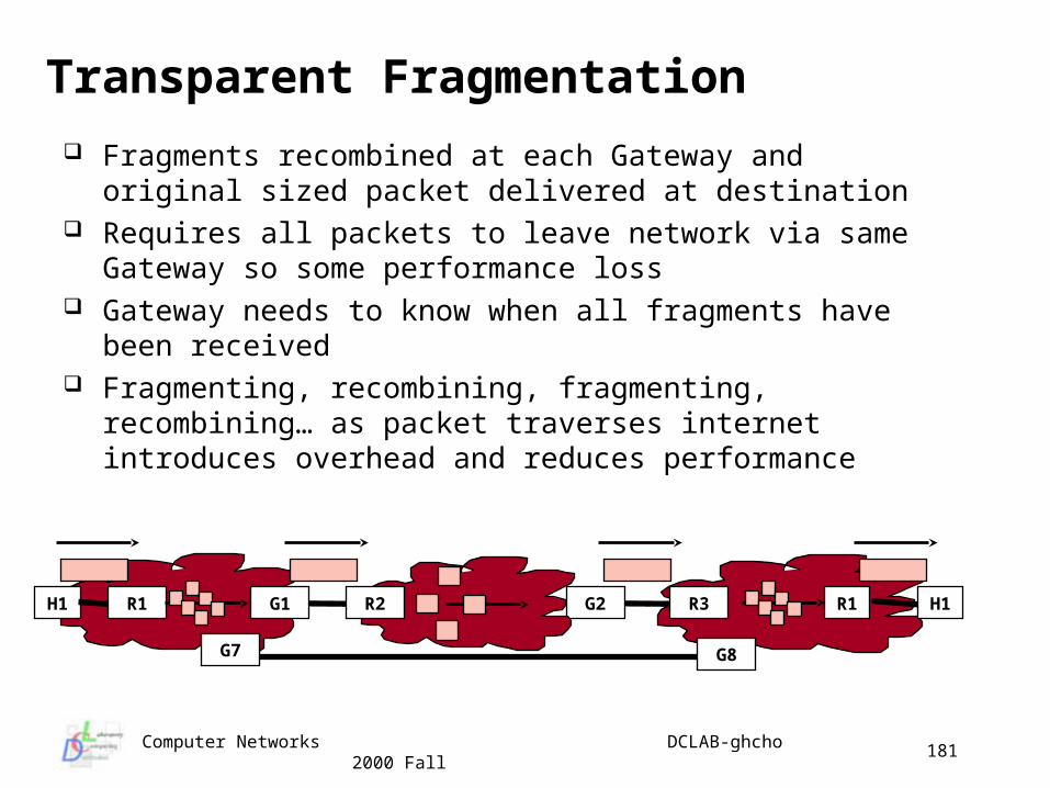
Transparent Fragmentation
Fragments recombined at each Gateway and original sized packet delivered at destination
Requires all packets to leave network via same Gateway so some performance loss
Gateway needs to know when all fragments have been received Fragmenting, recombining, fragmenting, recombining… as
packet traverses internet introduces overhead and reduces performance
G2G1 R3H1 R1R2R1 H1
G7 G8
Computer Networks DCLAB-ghcho 2000 Fall
182
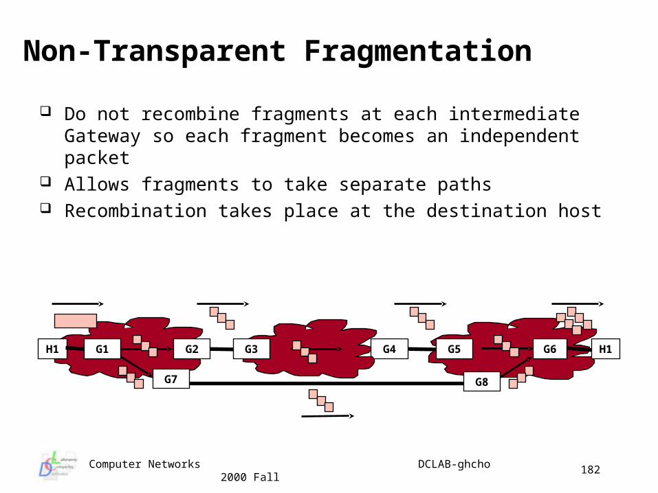
Non-Transparent Fragmentation
Do not recombine fragments at each intermediate Gateway so each fragment becomes an independent packet
Allows fragments to take separate paths Recombination takes place at the destination host
G4G2 G5H1 G3 H1G1
G7
G6
G8
Computer Networks DCLAB-ghcho 2000 Fall
183
The Internet Protocol (IP)
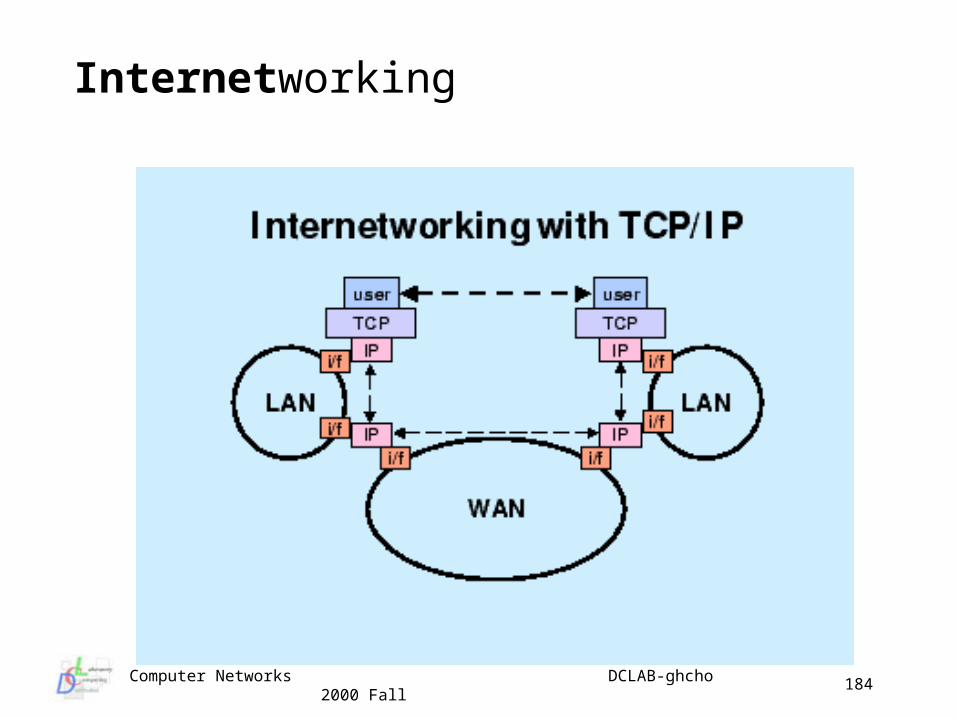
Internet is not a physical network, but it is a method of internetworking physical networks and a set of conventions for using networks that allow the computers they reach to Internet
The collection of networks and gateways that use the TCP/IP protocol suite and that function as a single, cooperative virtual network
A collection of autonomous systems (in other word ‘domain’) interconnected by one or more backbones
Loose, collaborative structure with AS’s organized into Regional Networks interconnected into the larger Internet
Developed from the DARPAnet, NSFnet and grew from the original TCP/IP protocol suite and was designed for internetworking from the start
Provides best effort datagram service to transport Layer
Computer Networks DCLAB-ghcho 2000 Fall
184
Internetworking
Computer Networks DCLAB-ghcho 2000 Fall
185
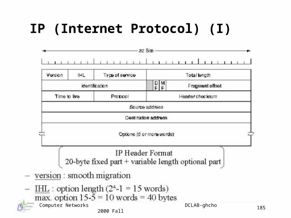
IP (Internet Protocol) (I)
Computer Networks DCLAB-ghcho 2000 Fall
186
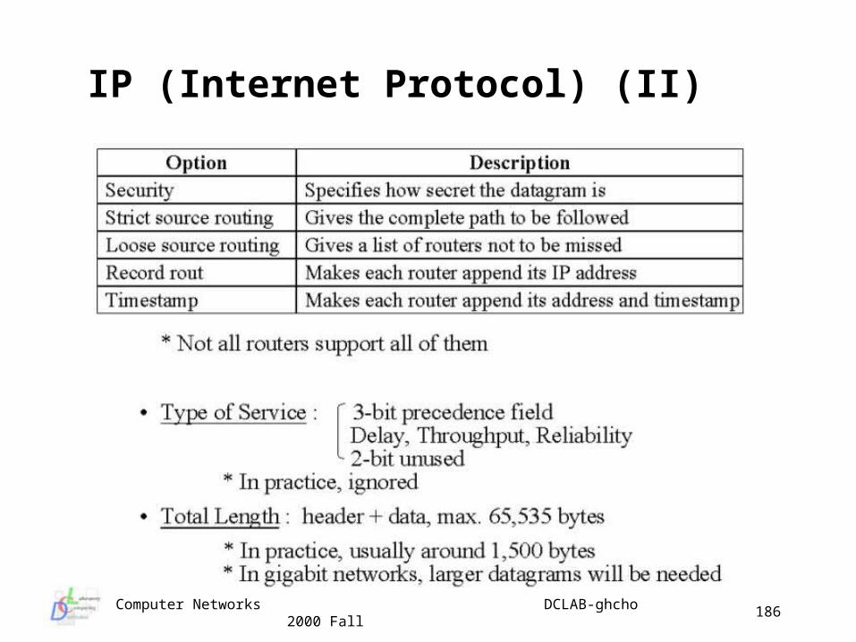
IP (Internet Protocol) (II)
Computer Networks DCLAB-ghcho 2000 Fall
187
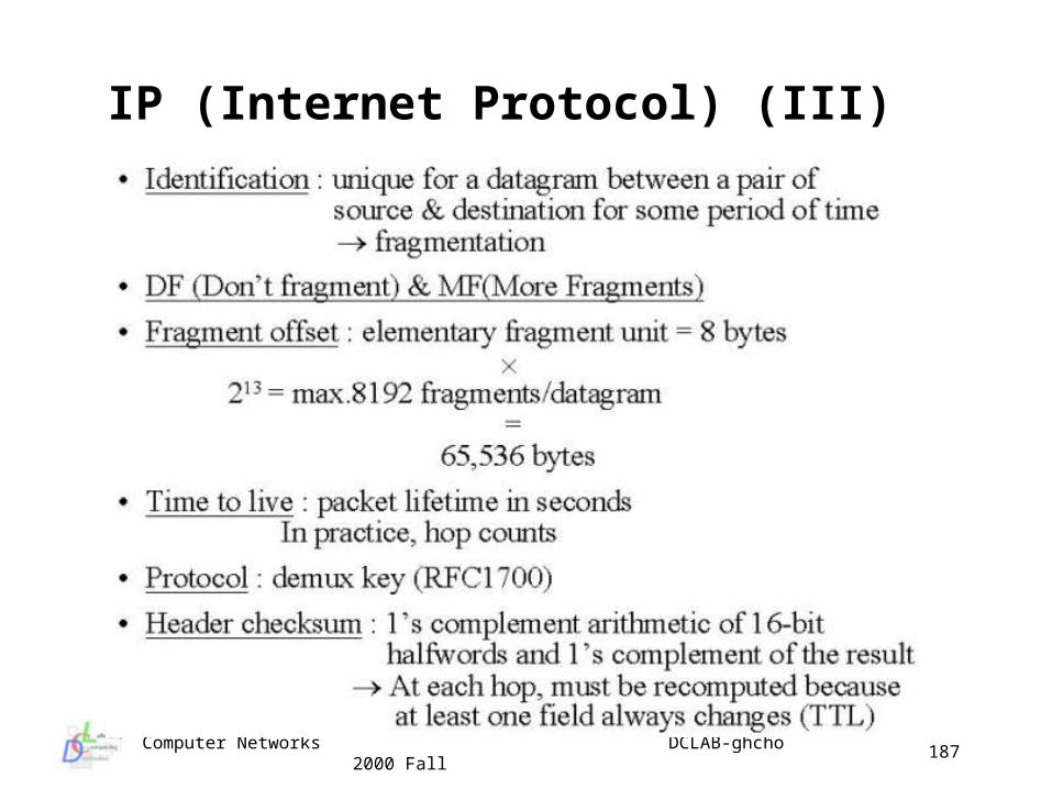
IP (Internet Protocol) (III)
Computer Networks DCLAB-ghcho 2000 Fall
188
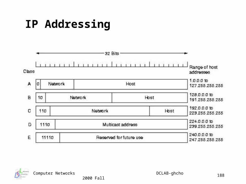
IP Addressing
Computer Networks DCLAB-ghcho 2000 Fall
189
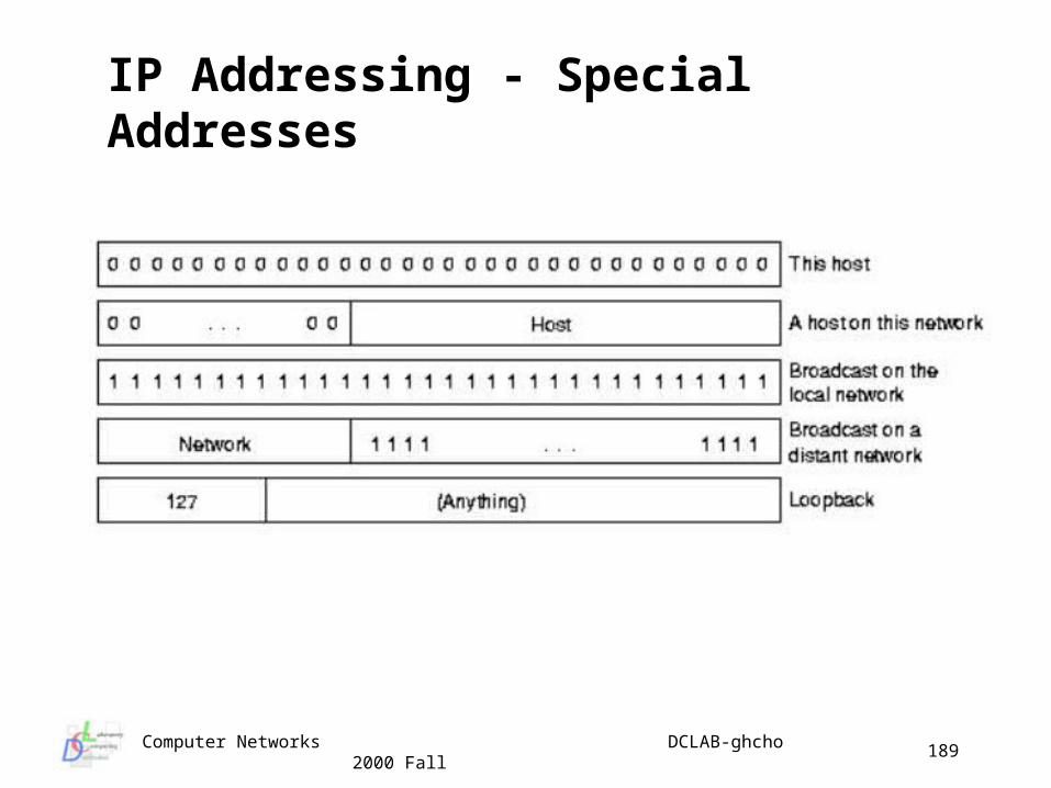
IP Addressing - Special Addresses
Computer Networks DCLAB-ghcho 2000 Fall
190
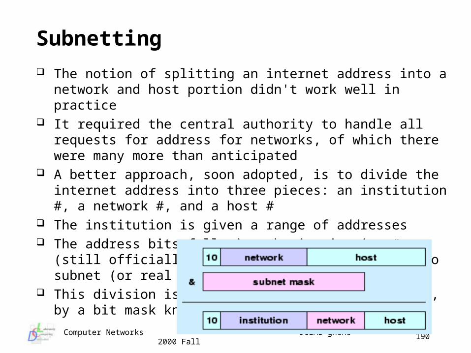
Subnetting
The notion of splitting an internet address into a network and host portion didn't work well in practice
It required the central authority to handle all requests for address for networks, of which there were many more than anticipated
A better approach, soon adopted, is to divide the internet address into three pieces: an institution #, a network #, and a host #
The institution is given a range of addresses The address bits following the institution # (still officially the network
#) are divided into subnet (or real network) number and host # This division is specified, for each institution, by a bit mask known
as the subnet mask
Computer Networks DCLAB-ghcho 2000 Fall
191
Internet Control Message Protocol (ICMP) IP Standards specify that compliant implementations must also
implement ICMP (RFC 792) ICMP provides a mechanism to provide feedback about problems
in the network ICMP packets may be sent by routers or hosts and are generated
“at the NL” ICMP exists at the NL but is a user of NL services - I.e. uses IP
datagram service ICMP packets are usually generated by a host or router in
response to a previous datagram ICMP packets have a 64 bit header which includes:
type (8 bits) - type of ICMP packet code (8 bits) - specifies parameters of the packet checksum (16 bits) - checksum for entire ICMP packet parameters (32 bits) - specifies parameters to large for Code
Computer Networks DCLAB-ghcho 2000 Fall
192
Types of ICMP Packets The header is usually followed by additional information depending
on packet type When the packet refers to a previous datagram the additional info. i
ncludes the IP header and first 64 bits of the original datagram Inclusion of first 64 bits of data after the IP header is to allow IP entit
y to determine which IP user was associated with the datagram Types of packets include:
destination unreachable - e.g. router can’t reach dst network time exceeded - TTL of datagram expires parameter error - semantic error in IP header Src Quench - simple flow control redirect - advise host of better route echo (reply) - test communications timestamp (reply) - allow determination of delay address mask req (reply) - inform host of LAN’s subnet mask
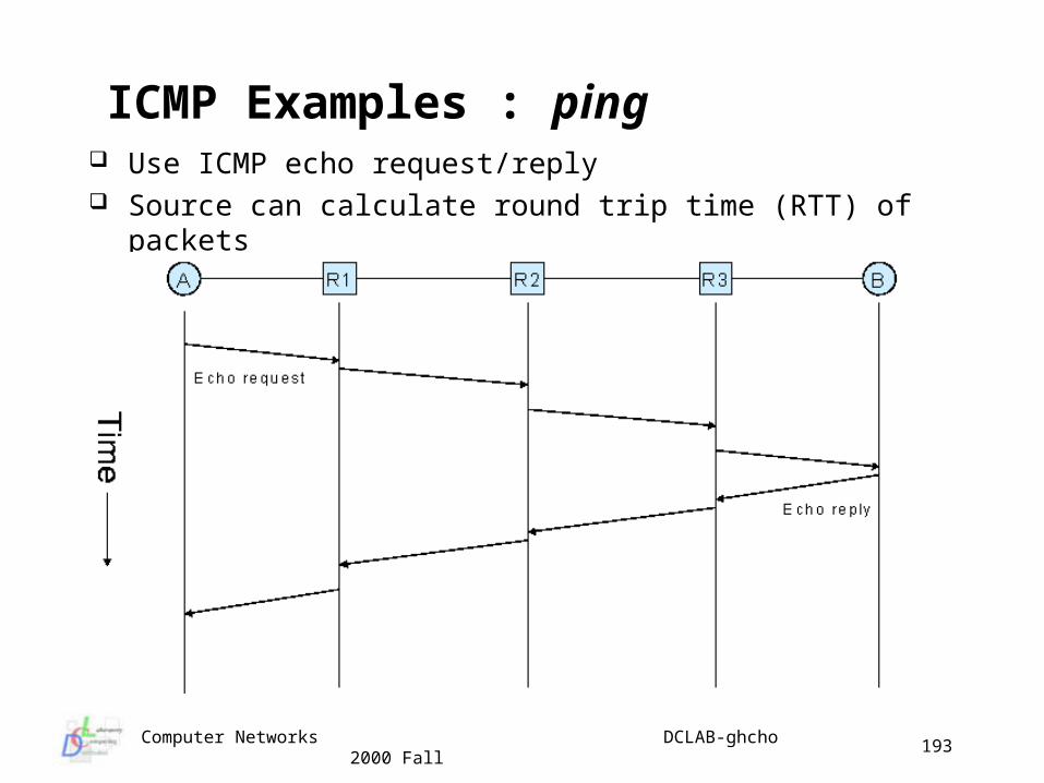
Computer Networks DCLAB-ghcho 2000 Fall
193
ICMP Examples : ping Use ICMP echo request/reply Source can calculate round trip time (RTT) of packets
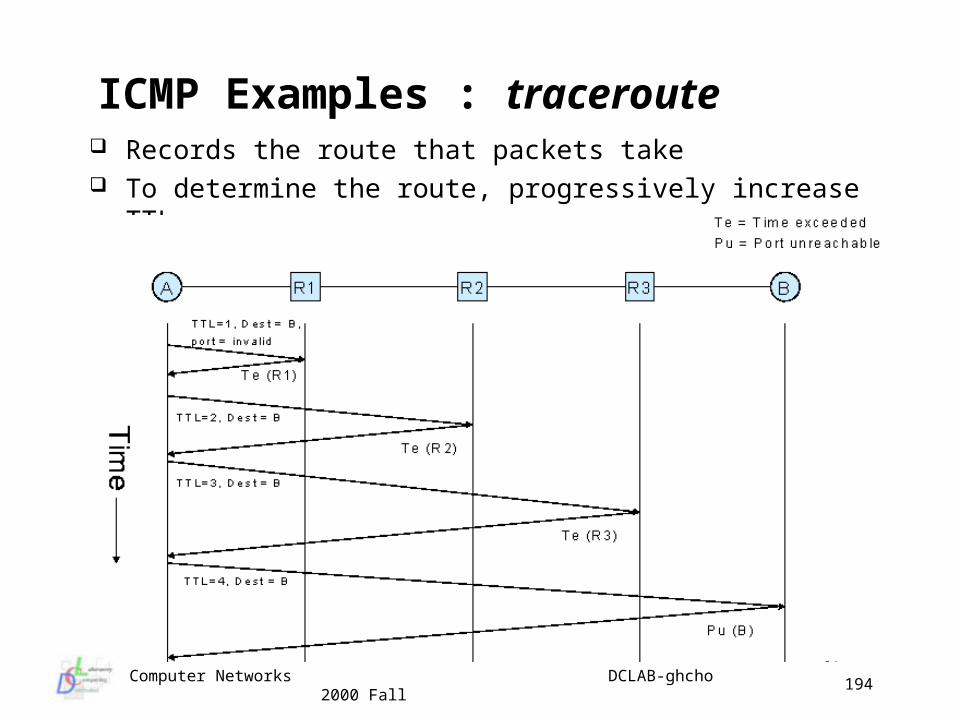
Computer Networks DCLAB-ghcho 2000 Fall
194
ICMP Examples : traceroute Records the route that packets take To determine the route, progressively increase TTL
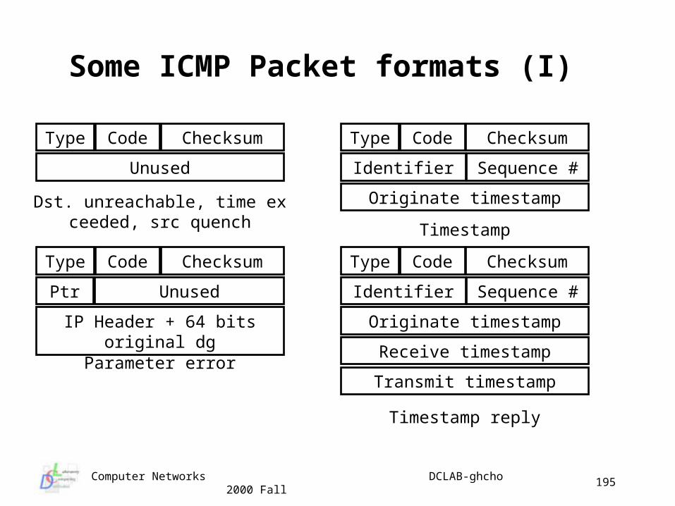
Computer Networks DCLAB-ghcho 2000 Fall
195
Some ICMP Packet formats (I)
Type Code Checksum
Unused
Type Code Checksum
Identifier Sequence #
Originate timestamp
Type Code Checksum
Ptr Unused
IP Header + 64 bits original dg
Type Code Checksum
Identifier Sequence #
Originate timestamp
Receive timestamp
Transmit timestamp
Dst. unreachable, time exceeded, src quench Timestamp
Parameter error
Timestamp reply
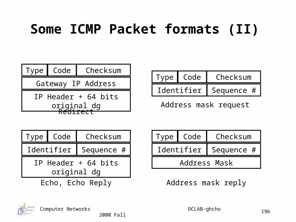
Computer Networks DCLAB-ghcho 2000 Fall
196
Some ICMP Packet formats (II)
Type Code Checksum
Identifier Sequence #
Address mask request
Echo, Echo Reply
Redirect
Type Code Checksum
Gateway IP Address
IP Header + 64 bits original dg
Type Code Checksum
Identifier Sequence #
IP Header + 64 bits original dg
Type Code Checksum
Identifier Sequence #
Address Mask
Address mask reply
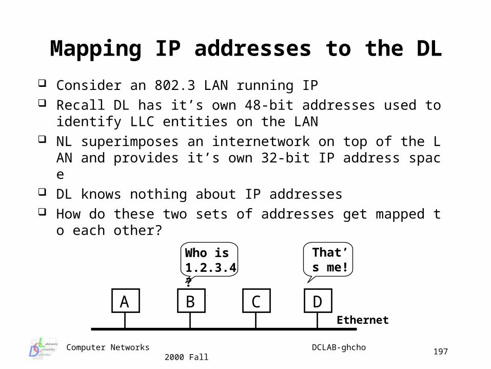
Computer Networks DCLAB-ghcho 2000 Fall
197
Mapping IP addresses to the DL
Consider an 802.3 LAN running IP Recall DL has it’s own 48-bit addresses used to identify LLC ent
ities on the LAN NL superimposes an internetwork on top of the LAN and provid
es it’s own 32-bit IP address space DL knows nothing about IP addresses How do these two sets of addresses get mapped to each other?
A B C D
Who is 1.2.3.4?
That’s me!
Ethernet
Computer Networks DCLAB-ghcho 2000 Fall
198
Address Resolution Protocol (ARP) (I) Another control protocol which resides at the NL is ARP ARP builds a DL broadcast frame with a packet “what’s the DL addre
ss for IP address w.x.y.z?” and sends it Broadcast frame is received by all hosts and one says “that’s me!” or
another says “I know” Host recognizing the IP address builds a response giving the DL addr
ess to IP address mapping and sends it to the sender This is a simple and effective protocol which eliminates need for main
taining static tables A sender broadcasts the ARP request packet with it’s destination xfffff
fffffff address field But, the broadcasting is too expensive to use repeatedly whenever a
host wants to send a packet How can it be solved? When a host receives an ARP reply, it saves the sender’s IP address
and corresponding physical address in its cache for successive lookups
Computer Networks DCLAB-ghcho 2000 Fall
199
Address Resolution Protocol (ARP) (II) Is it be possible more refinement? The sender’s IP-to-physical address binding is included in every ARP
broadcast; receivers update the binding information in their cache ARP is a low-level protocol that hides the underlying network physical
addressing, permitting one to assign an arbitrary IP address to every machine
ARP is a part of the physical network system, and is not a part of the internet protocols
Reverse address resolutoin protocol (RARP) ARP finds out Ethernet address that corresponds to a given IP RARP finds the IP address of the host using an Ethernet address
associated with the Ethernet card• when the machine is booted, it broadcasts its 48-bit Ethernet a
ddress and ask for its IP address• RARP server that is available at each network responds with t
he IP address
Computer Networks DCLAB-ghcho 2000 Fall
200
The Internet Routing Architecture Internet = a core system + a set of autonomous systems The core system is the glue, as which
is controlled by the INOC(Internet Network Operations Center) provides reliable and consistent routers for all possible dest. does not use the default route has complete infor. about optimal routes to all possible dest.
The autonomous system is an ever-growing component of core system, as which is a collection of networks and gateways managed by one admin
istrative authority are hierarchically grouped into an autonomous system (nesting) allows gateways to advertise only the reachability of those netwo
rks within the gateway’s autonomous system restricts the Internet’s topology to a tree structure in which a core
system forms the root - only one path from the core system
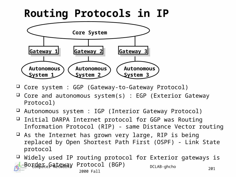
Computer Networks DCLAB-ghcho 2000 Fall
201
Routing Protocols in IP
Core system : GGP (Gateway-to-Gateway Protocol) Core and autonomous system(s) : EGP (Exterior Gateway Protocol) Autonomous system : IGP (Interior Gateway Protocol) Initial DARPA Internet protocol for GGP was Routing Information
Protocol (RIP) - same Distance Vector routing As the Internet has grown very large, RIP is being replaced by Open
Shortest Path First (OSPF) - Link State protocol Widely used IP routing protocol for Exterior gateways is Border
Gateway Protocol (BGP)
Core System
Gateway 1 Gateway 3Gateway 2
Autonomous System 1
Autonomous System 3
Autonomous System 2
Computer Networks DCLAB-ghcho 2000 Fall
202
Table Driven IP Routing The IP routing algorithm employs an Internet routing table on each
machine (host and router), which contains information about the possible destinations and how to reach them
It consults the table to decide where to send the datagram Then what information should be kept in routing tables?
minimal information principle : keep network prefix only- makes routing efficient and keeps routing table small
information hiding principle : the details of specific hosts confined to the local environment : next- hop routing
- the routing table in a router only specifies one step along the path from the router to a destination
Default routing : If no route appears in the table, the routing routines send the datagram to a default router it makes their routing decisions efficiently to possible distant
destinations
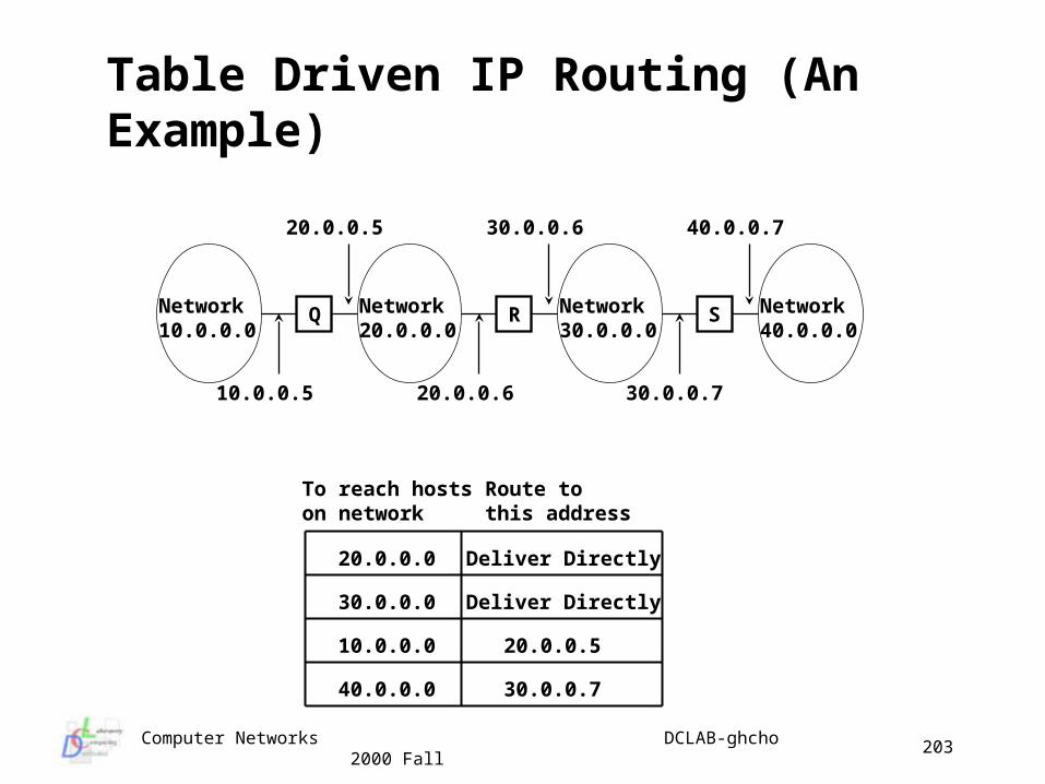
Computer Networks DCLAB-ghcho 2000 Fall
203
Table Driven IP Routing (An Example)
Network10.0.0.0
Q Network20.0.0.0
R Network30.0.0.0
S Network40.0.0.0
40.0.0.720.0.0.5
20.0.0.6
30.0.0.6
30.0.0.710.0.0.5
To reach hostson network
30.0.0.0
Route tothis address
10.0.0.0
40.0.0.0
20.0.0.0 Deliver Directly
Deliver Directly
20.0.0.5
30.0.0.7
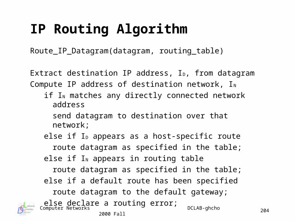
Computer Networks DCLAB-ghcho 2000 Fall
204
IP Routing Algorithm
Route_IP_Datagram(datagram, routing_table)
Extract destination IP address, ID, from datagram
Compute IP address of destination network, IN
if IN matches any directly connected network address
send datagram to destination over that network;
else if ID appears as a host-specific route
route datagram as specified in the table;
else if IN appears in routing table
route datagram as specified in the table;
else if a default route has been specified
route datagram to the default gateway;
else declare a routing error;
Computer Networks DCLAB-ghcho 2000 Fall
205
Routing Protocols in IP IP routing is based on the destination network ID alone, what?
all IP traffic for a given network tales the same path regardless to the delay or throughput of physical network
only the final router can determine if the destination exists or is operational, the router only can report the delivery to the sender
each router routes traffic independently - someone should find out if two-way communication is always possible
IP routing selects the next hop to be sent the datagram, what? where does IP store the next hop address? not IP itself! IP simply passes the datagram and the next hop address to the
network interface software (so-called network driver) the driver software responsible for the physical network over
which the datagram must be sent - binds the next hop IP address to a physical address, forms a frame, and sends it
Computer Networks DCLAB-ghcho 2000 Fall
206
IPv6 Protocol
IPv6 is the formal name of the protocol recommended by the IETF’ IPng group, its objectives are: support large global internetwork support new low-end Internet devices (PDAs, mobile comput
ers, consumers, devices) support the networked multimedia services
The Challenges from IPv4 plenty of addresses reduced administrative overhead opportunity for better routing support for address renumbering improved header processing reasonable security support for host mobility QoS control capability
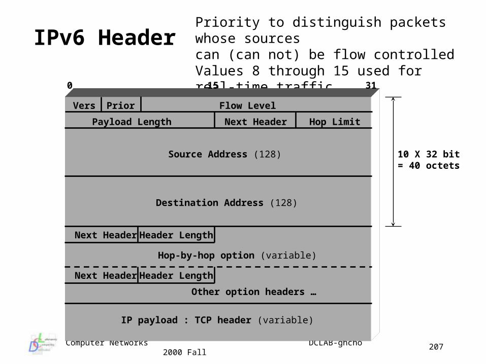
Computer Networks DCLAB-ghcho 2000 Fall
207
IPv6 HeaderPriority to distinguish packets whose sourcescan (can not) be flow controlledValues 8 through 15 used for real-time traffic
Vers Prior Flow Level
Payload Length Next Header Hop Limit
Source Address (128)
Destination Address (128)
15 310
Other option headers …
IP payload : TCP header (variable)
Next HeaderHeader Length
Hop-by-hop option (variable)
Next HeaderHeader Length
10 X 32 bit= 40 octets
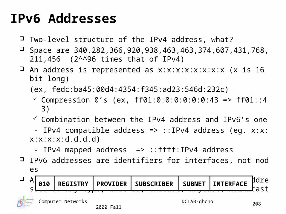
Computer Networks DCLAB-ghcho 2000 Fall
208
IPv6 Addresses
Two-level structure of the IPv4 address, what? Space are 340,282,366,920,938,463,463,374,607,431,768,211,456
(2^^96 times that of IPv4) An address is represented as x:x:x:x:x:x:x:x (x is 16 bit long)
(ex, fedc:ba45:00d4:4354:f345:ad23:546d:232c) Compression 0’s (ex, ff01:0:0:0:0:0:0:43 => ff01::43) Combination between the IPv4 address and IPv6’s one
- IPv4 compatible address => ::IPv4 address (eg. x:x:x:x:x:x:d.d.d.d)
- IPv4 mapped address => ::ffff:IPv4 address IPv6 addresses are identifiers for interfaces, not nodes A single interface may be assigned multiple IPv6 addresses of any t
ype, that is, unicast, anycast, multicast
010 REGISTRY INTERFACESUBNETSUBSCRIBERPROVIDER
Computer Networks DCLAB-ghcho 2000 Fall
209
Lecture Topic 5
Transport Layer
Transport layer concepts Protocol layering Port number TCP protocol TCP flow control TCP congestion control TCP protocol congestion UDP protocol Network programming interfaces
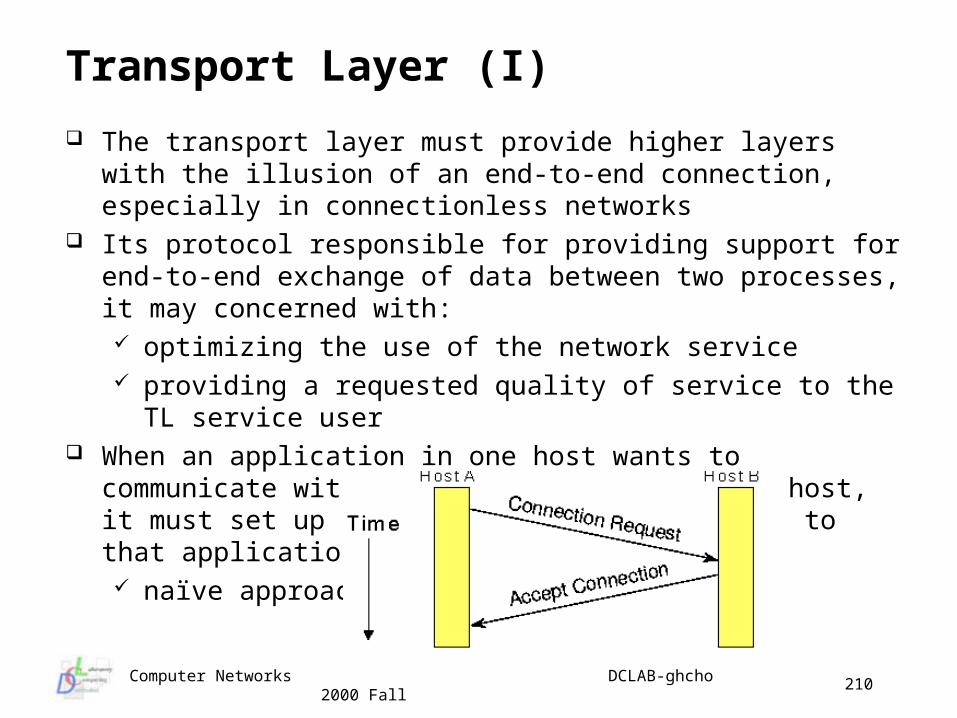
Computer Networks DCLAB-ghcho 2000 Fall
210
Transport Layer (I)
The transport layer must provide higher layers with the illusion of an end-to-end connection, especially in connectionless networks
Its protocol responsible for providing support for end-to-end exchange of data between two processes, it may concerned with: optimizing the use of the network service providing a requested quality of service to the TL service user
When an application in one host wants to communicate with an application in another host, it must set up a transport layer connection to that application naïve approach
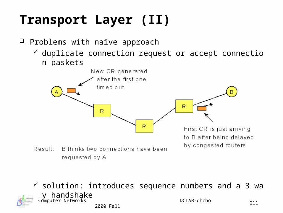
Computer Networks DCLAB-ghcho 2000 Fall
211
Transport Layer (II)
Problems with naïve approach duplicate connection request or accept connection paskets
solution: introduces sequence numbers and a 3 way handshake
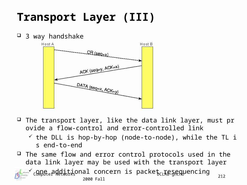
Computer Networks DCLAB-ghcho 2000 Fall
212
Transport Layer (III)
3 way handshake
The transport layer, like the data link layer, must provide a flow-control and error-controlled link the DLL is hop-by-hop (node-to-node), while the TL is end-to-end
The same flow and error control protocols used in the data link layer may be used with the transport layer one additional concern is packet resequencing
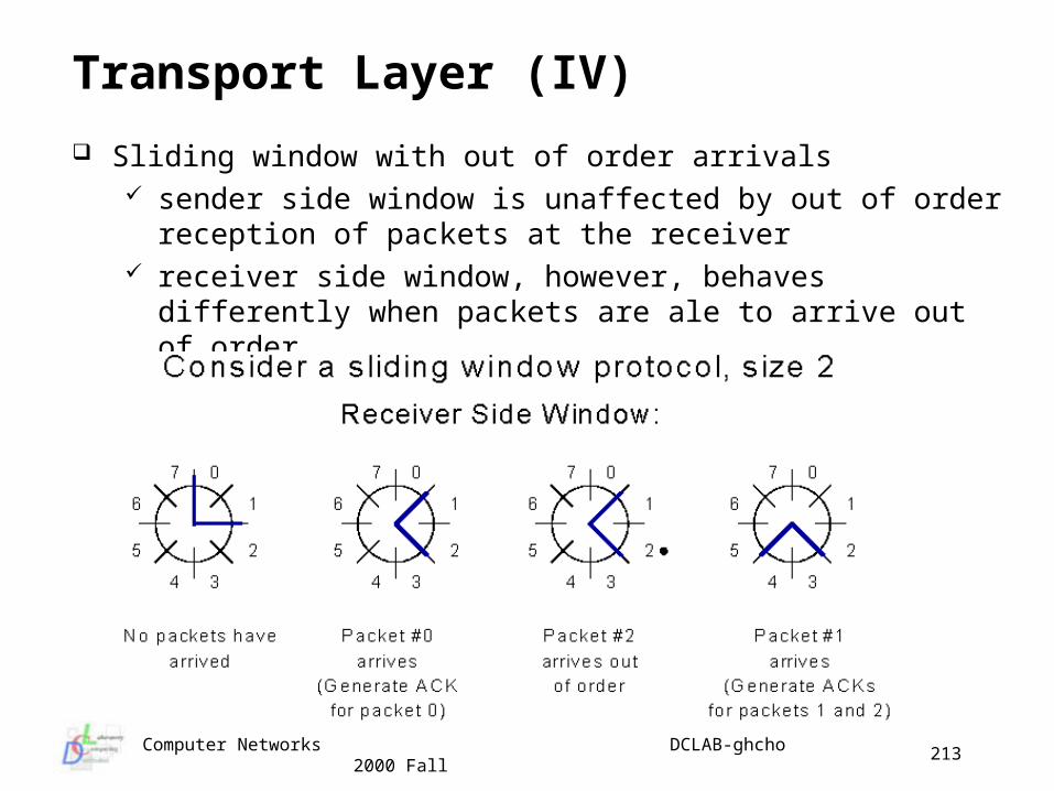
Computer Networks DCLAB-ghcho 2000 Fall
213
Transport Layer (IV)
Sliding window with out of order arrivals sender side window is unaffected by out of order reception of
packets at the receiver receiver side window, however, behaves differently when packets
are ale to arrive out of order
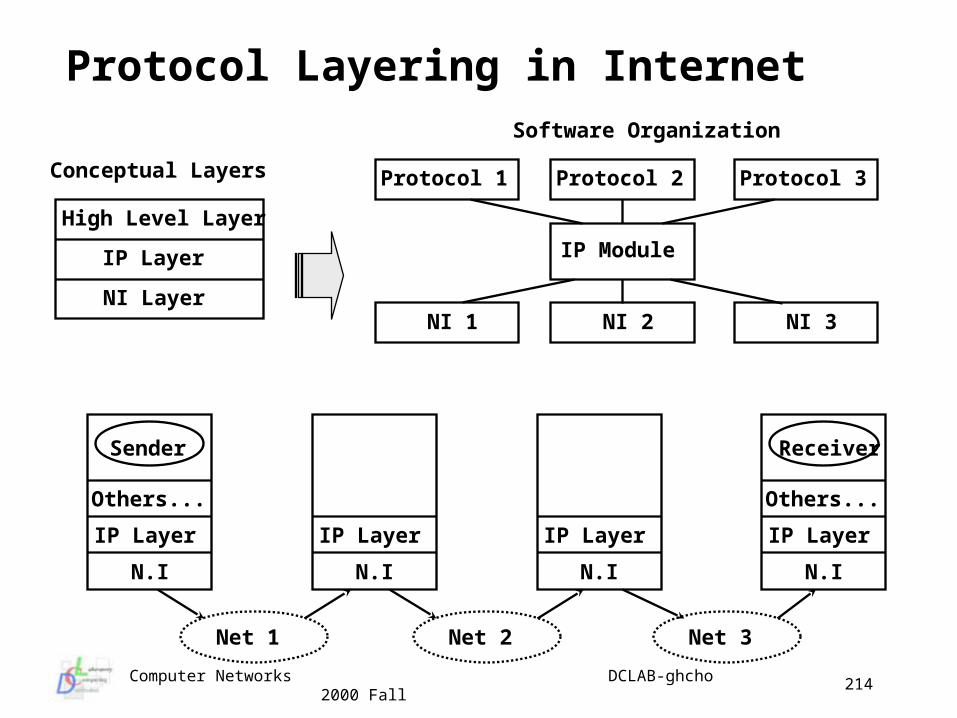
Computer Networks DCLAB-ghcho 2000 Fall
214
Protocol Layering in Internet
IP Layer
N.I
Others...
Sender
Net 1
IP Layer
N.I
IP Layer
N.I
Others...
Receiver
IP Layer
N.I
Net 2 Net 3
High Level Layer
IP Layer
NI Layer
Conceptual Layers
Software Organization
Protocol 1 Protocol 3Protocol 2
IP Module
NI 1 NI 2 NI 3
Computer Networks DCLAB-ghcho 2000 Fall
215
Transport Layer Responsible for providing support for end-to-end exchange of data b
etween two processes TL may be concerned with optimizing the use of the network service TL may be concerned with providing a requested quality of service t
o the TL service user Two TL protocols - Transport Control Protocol (TCP) and User Data
gram Protocol (UDP) TCP is connection oriented UDP is connectionless (minimal service on top of IP)
TCP provides reliable byte-stream communications between a pair of TCP user processes across an unreliable network
Functionally equivalent to Class 4 ISO Transport but TCP is stream oriented
TCP was designed to dynamically adapt to properties of the internetwork and being robust to many kinds of failures
Computer Networks DCLAB-ghcho 2000 Fall
216
TCP A TCP entity runs on each host supporting the TCP/IP protocol suite The entity may be a kernel process which interacts with the IP entity TCP users exchange streams of data bytes but TCP entity breaks these
up into segments of 64KB or less for transmission TCP service is obtained by having both the sender and receiver create
end points (sockets) each socket has a socket number (address) consisting of
IP address of the host 16-bit number local to the host (port)
connections are identified by the socket identifiers at both ends (socket1, socket2)
Current operating system support multiprogramming multiple applications would be executed simultaneously; multitask
Computer Networks DCLAB-ghcho 2000 Fall
217
Port Number (I) A process is the ultimate destination for a message, but IP delivers a
datagram to only the destination host, and processes are created and destroyed dynamically process identifier would be changed in times much reasonable to identify destinations from the functions
Instead of thinking of a process as the ultimate destination, Internet provides a set of abstract destination points called protocol port, which is possible for more than one user process at a time to be using either
TCP or UDP consist of 16-bit integer
When a client process wants to contact a server, the client must have a way of identifying the server that it wants assuming that the client knows the server’s IP address, how does
the client identify the particular server process To solve this problem, a group of well-known ports are defined
the port 1 - 255 (1 - 1023 for BSD UNIX) are reserved
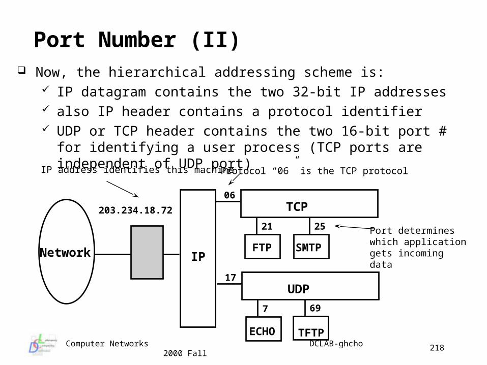
Computer Networks DCLAB-ghcho 2000 Fall
218
Port Number (II) Now, the hierarchical addressing scheme is:
IP datagram contains the two 32-bit IP addresses also IP header contains a protocol identifier UDP or TCP header contains the two 16-bit port # for identifying a
user process (TCP ports are independent of UDP port)
Network IP
06TCP
21 25
FTP SMTP
Protocol “06” is the TCP protocol
Port determineswhich applicationgets incomingdata
17UDP
7
ECHO
69
TFTP
203.234.18.72
IP address identifies this machine
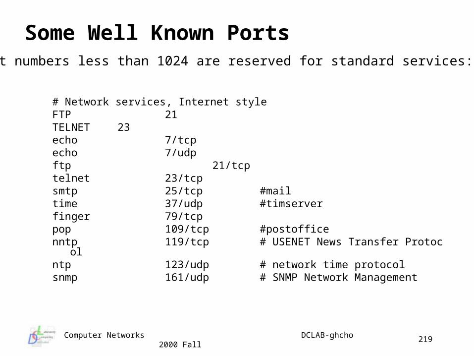
Computer Networks DCLAB-ghcho 2000 Fall
219
# Network services, Internet styleFTP 21TELNET 23echo 7/tcpecho 7/udpftp 21/tcptelnet 23/tcpsmtp 25/tcp #mailtime 37/udp #timserverfinger 79/tcppop 109/tcp #postofficenntp 119/tcp # USENET News Transfer Protocolntp 123/udp # network time protocolsnmp 161/udp # SNMP Network Management
Some Well Known PortsPort numbers less than 1024 are reserved for standard services:
Computer Networks DCLAB-ghcho 2000 Fall
220
TCP Service Model
TCP connection is a byte stream and not a message stream if a sending process writes 4 512-byte chunks to a TCP stream
it might be delivered as 4 512 byte chunks two 1024 byte chunks one 2048 byte chunk
the data can be sent immediately or buffered it in order to collect a larger amount to send at once
TCP provides a push mechanism to send data immediately without any delay user can require TCP to transmit all outstanding data by setting
the PUSH flag receiver TCP delivers this pushed data immediately
TCP provides an urgent mechanism TCP allows user to mark data as urgent (CTRL-C) TCP user at receiving end decides what to do in response
Computer Networks DCLAB-ghcho 2000 Fall
221
TCP Protocol IP datagrams with TCP specified in protocol field are presented to
the TCP entity to reconstruct data streams TCP entity uses timers to deal with lost packets, retransmission a
nd out of order Use sliding window protocol - receiver ack refers to the next expe
cted segment TCP has only one type of TPDU - segment Minimum header size is 20 octets
segment must fit in maximum IP packet 65535 B each network has a maximum transfer unit(MTU) and each se
gment must fit in that MTU
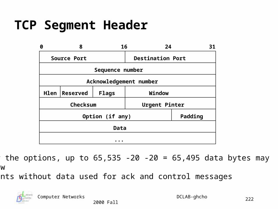
Computer Networks DCLAB-ghcho 2000 Fall
222
TCP Segment Header
After the options, up to 65,535 -20 -20 = 65,495 data bytes may followsegments without data used for ack and control messages
Source Port
0 8 16 24 31
Sequence number
Option (if any)
Destination Port
Checksum
Acknowledgement number
...
Data
Urgent Pinter
WindowHlen Reserved Flags
Padding
Computer Networks DCLAB-ghcho 2000 Fall
223
TCP TPDU Header Fields (I) Source/destination Ports - defines the local end points of the co
nnection Sequence Number - Sequence # of first data octet in the segme
nt except if SYN flag is set, then it’s initial sequence number N and first data octet is N+1
Ack number refers to the next byte expected seq and ack are both 32 bits long because every byte in TCP str
eam is numbered TCP Header Length - Number of 32-bit words in the TCP heade
r Reserved - 6 bits reserved for future use
Computer Networks DCLAB-ghcho 2000 Fall
224
TCP TPDU Header Fields (II) Flags
URG - Urgent pointer field is used to indicate a byte offset from the current urgent data
ACK - Acknowledgement field is valid/ignored PSH - to indicate that data is PUSHED RST - Reset the connection due to crashes, failures SYN - is used to establish connections FIN - release connection No more data sent
Flow control is handled using variable-size sliding window window size 0 is legal
Checksum - add all 16-bit words in One’s complement and then take the 1’s complement of the sum
options used to add new capabilities use large segment to reduce header overhead increase window size from 16 bits to 30 bits
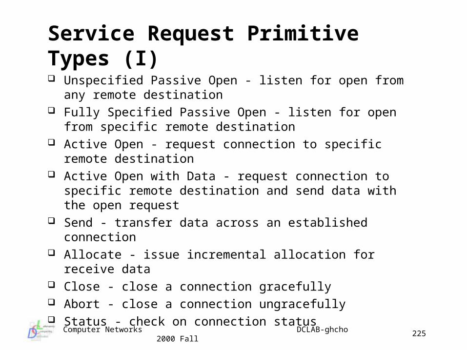
Computer Networks DCLAB-ghcho 2000 Fall
225
Service Request Primitive Types (I)
Unspecified Passive Open - listen for open from any remote destination
Fully Specified Passive Open - listen for open from specific remote destination
Active Open - request connection to specific remote destination
Active Open with Data - request connection to specific remote destination and send data with the open request
Send - transfer data across an established connection Allocate - issue incremental allocation for receive data Close - close a connection gracefully Abort - close a connection ungracefully Status - check on connection status
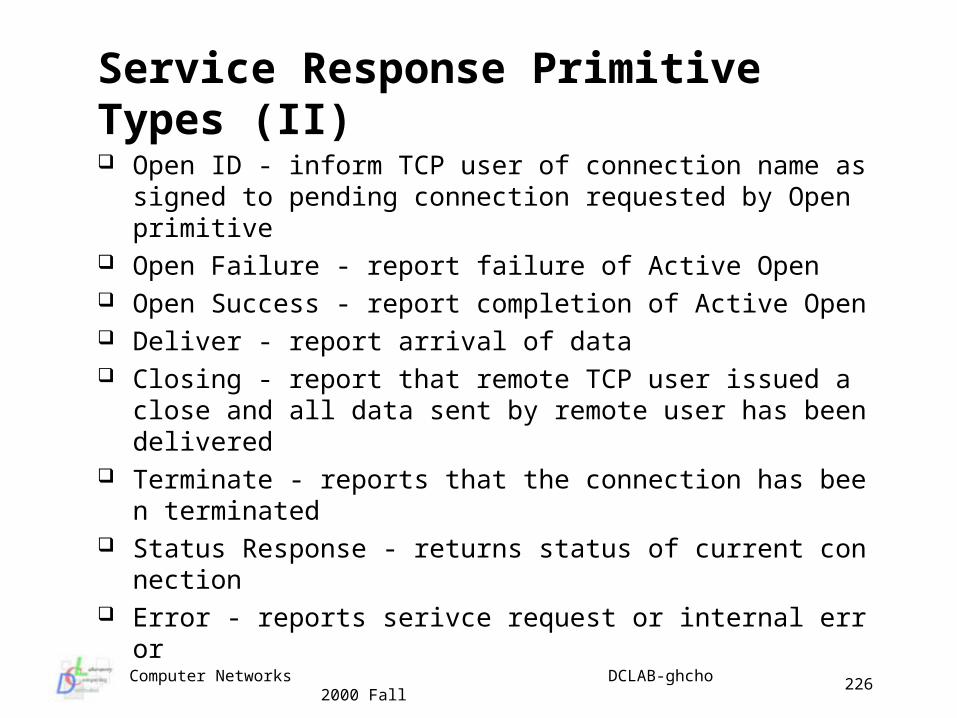
Computer Networks DCLAB-ghcho 2000 Fall
226
Service Response Primitive Types (II)
Open ID - inform TCP user of connection name assigned to pending connection requested by Open primitive
Open Failure - report failure of Active Open Open Success - report completion of Active Open Deliver - report arrival of data Closing - report that remote TCP user issued a close and all d
ata sent by remote user has been delivered Terminate - reports that the connection has been terminated Status Response - returns status of current connection Error - reports serivce request or internal error
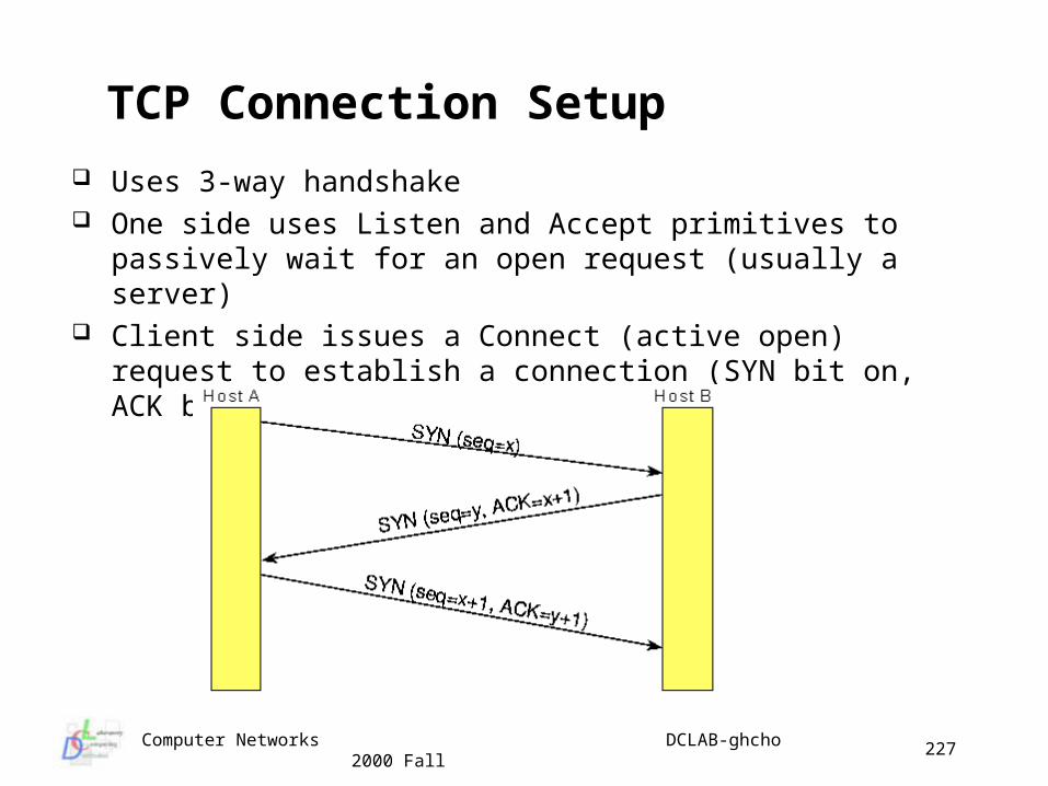
Computer Networks DCLAB-ghcho 2000 Fall
227
TCP Connection Setup
Uses 3-way handshake One side uses Listen and Accept primitives to passively wait for an
open request (usually a server) Client side issues a Connect (active open) request to establish a
connection (SYN bit on, ACK bit off)
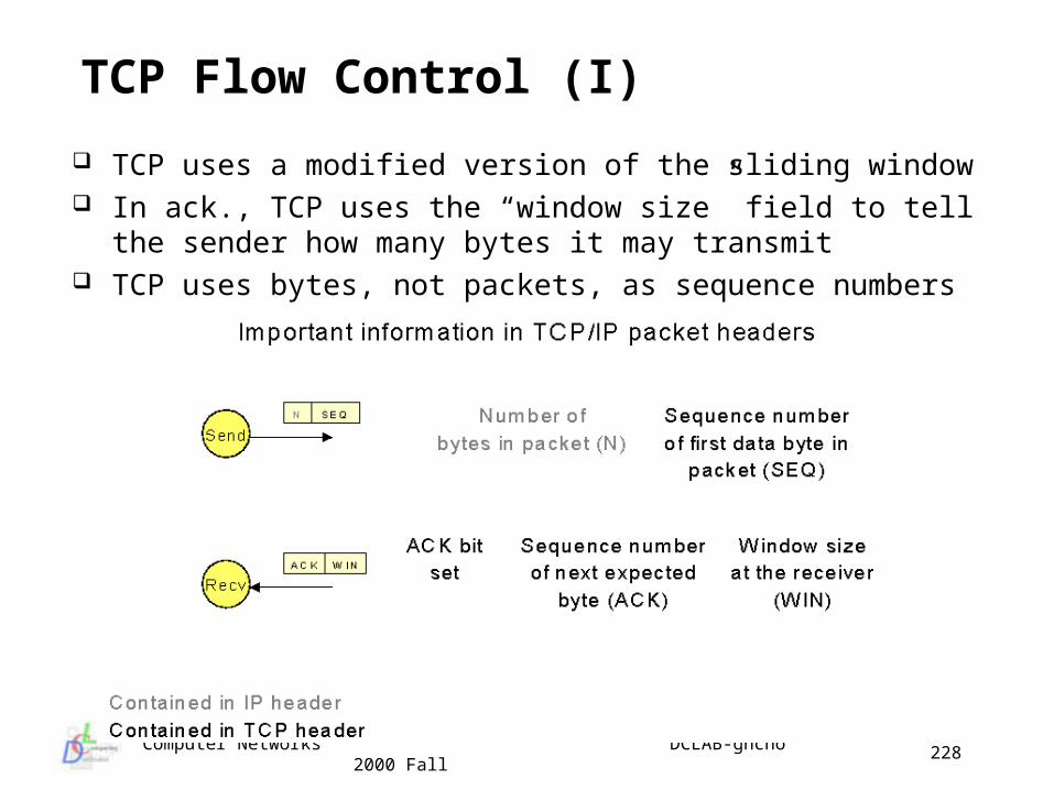
Computer Networks DCLAB-ghcho 2000 Fall
228
TCP Flow Control (I)
TCP uses a modified version of the sliding window In ack., TCP uses the “window size” field to tell the sender how ma
ny bytes it may transmit TCP uses bytes, not packets, as sequence numbers
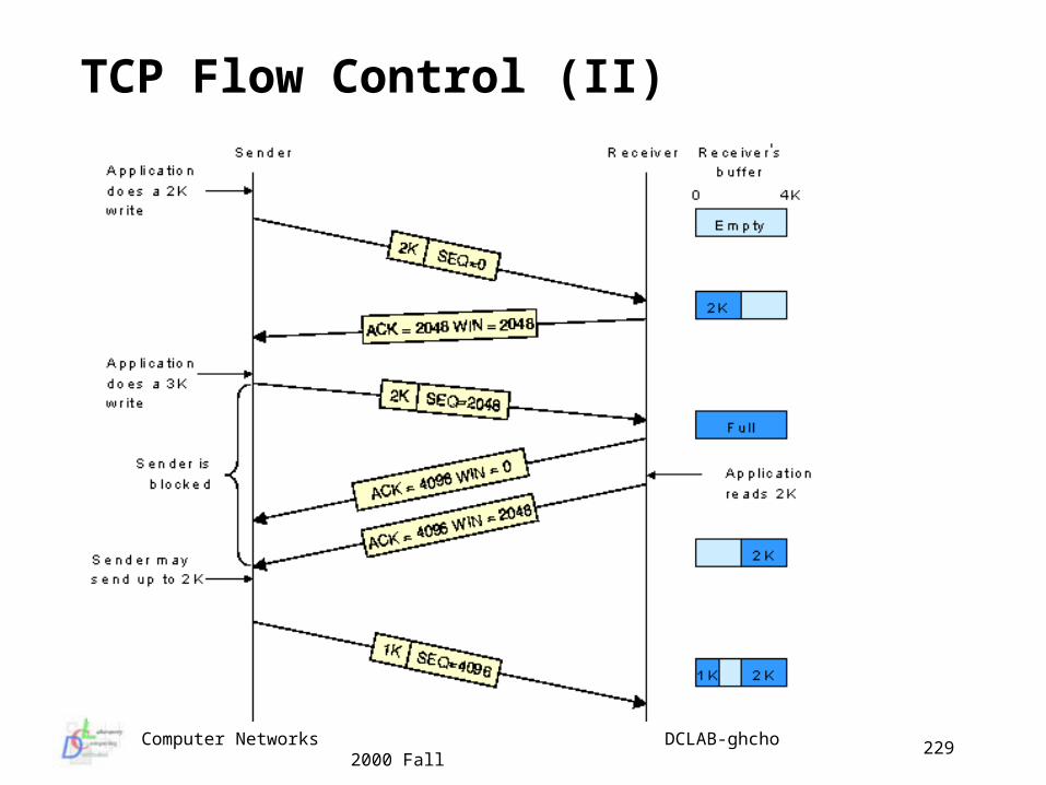
Computer Networks DCLAB-ghcho 2000 Fall
229
TCP Flow Control (II)
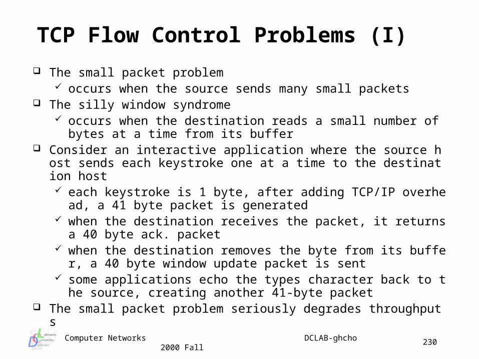
Computer Networks DCLAB-ghcho 2000 Fall
230
TCP Flow Control Problems (I)
The small packet problem occurs when the source sends many small packets
The silly window syndrome occurs when the destination reads a small number of bytes at a
time from its buffer Consider an interactive application where the source host sends e
ach keystroke one at a time to the destination host each keystroke is 1 byte, after adding TCP/IP overhead, a 41 b
yte packet is generated when the destination receives the packet, it returns a 40 byte a
ck. packet when the destination removes the byte from its buffer, a 40 byt
e window update packet is sent some applications echo the types character back to the source,
creating another 41-byte packet The small packet problem seriously degrades throughputs
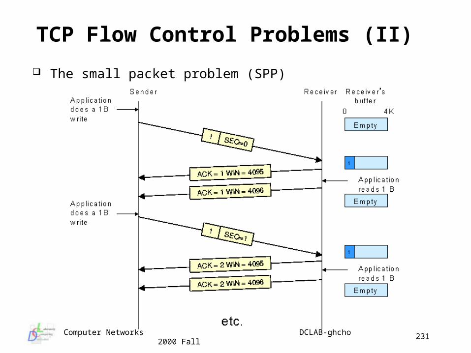
Computer Networks DCLAB-ghcho 2000 Fall
231
TCP Flow Control Problems (II)
The small packet problem (SPP)
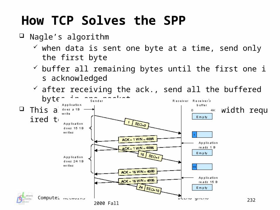
Computer Networks DCLAB-ghcho 2000 Fall
232
How TCP Solves the SPP Nagle’s algorithm
when data is sent one byte at a time, send only the first byte buffer all remaining bytes until the first one is acknowledged after receiving the ack., send all the buffered bytes in one packet
This algorithm reduces the amount of bandwidth required to support interactive applications
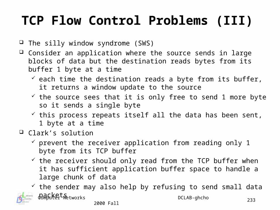
Computer Networks DCLAB-ghcho 2000 Fall
233
TCP Flow Control Problems (III)
The silly window syndrome (SWS) Consider an application where the source sends in large blocks of
data but the destination reads bytes from its buffer 1 byte at a time each time the destination reads a byte from its buffer, it returns a
window update to the source the source sees that it is only free to send 1 more byte so it sends
a single byte this process repeats itself all the data has been sent, 1 byte at a
time Clark’s solution
prevent the receiver application from reading only 1 byte from its TCP buffer
the receiver should only read from the TCP buffer when it has sufficient application buffer space to handle a large chunk of data
the sender may also help by refusing to send small data packets
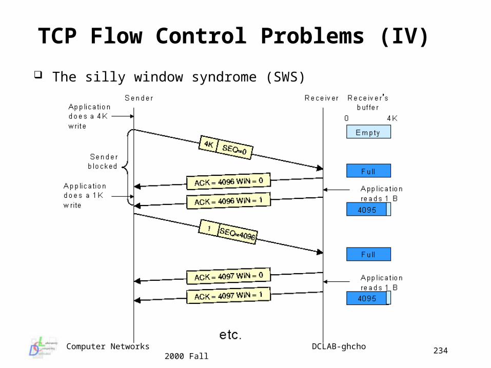
Computer Networks DCLAB-ghcho 2000 Fall
234
TCP Flow Control Problems (IV)
The silly window syndrome (SWS)
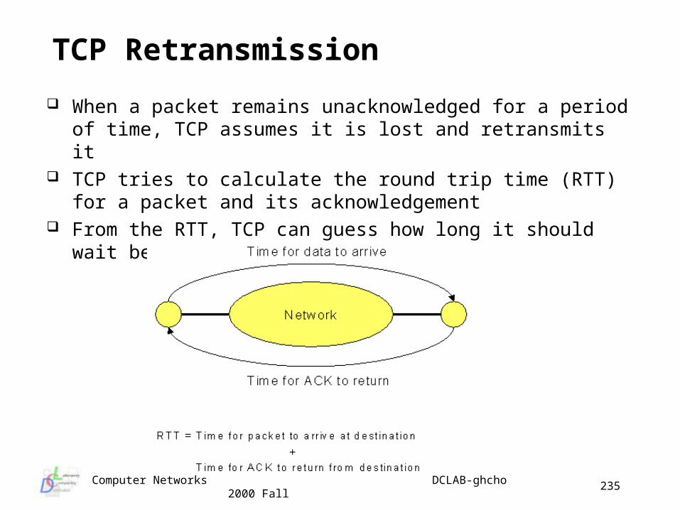
Computer Networks DCLAB-ghcho 2000 Fall
235
TCP Retransmission
When a packet remains unacknowledged for a period of time, TCP assumes it is lost and retransmits it
TCP tries to calculate the round trip time (RTT) for a packet and its acknowledgement
From the RTT, TCP can guess how long it should wait before timing out
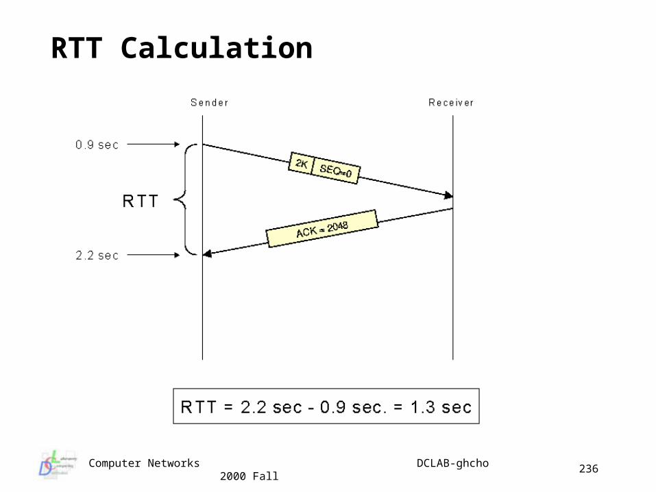
Computer Networks DCLAB-ghcho 2000 Fall
236
RTT Calculation
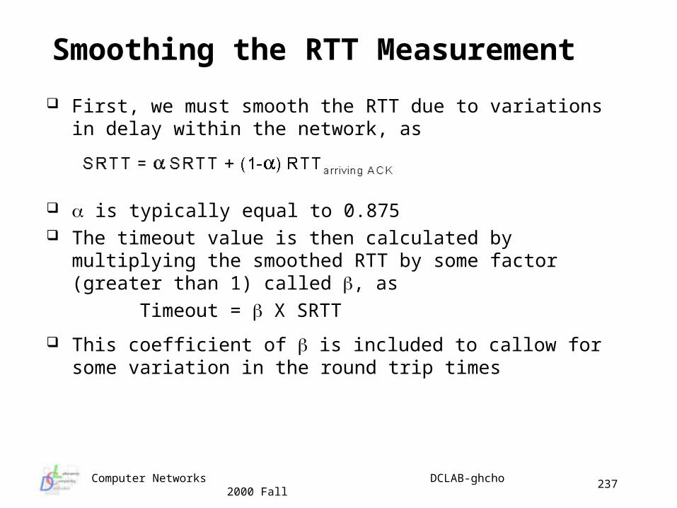
Computer Networks DCLAB-ghcho 2000 Fall
237
Smoothing the RTT Measurement
First, we must smooth the RTT due to variations in delay within the network, as
is typically equal to 0.875 The timeout value is then calculated by multiplying the smoothed
RTT by some factor (greater than 1) called , as
Timeout = X SRTT
This coefficient of is included to callow for some variation in the round trip times
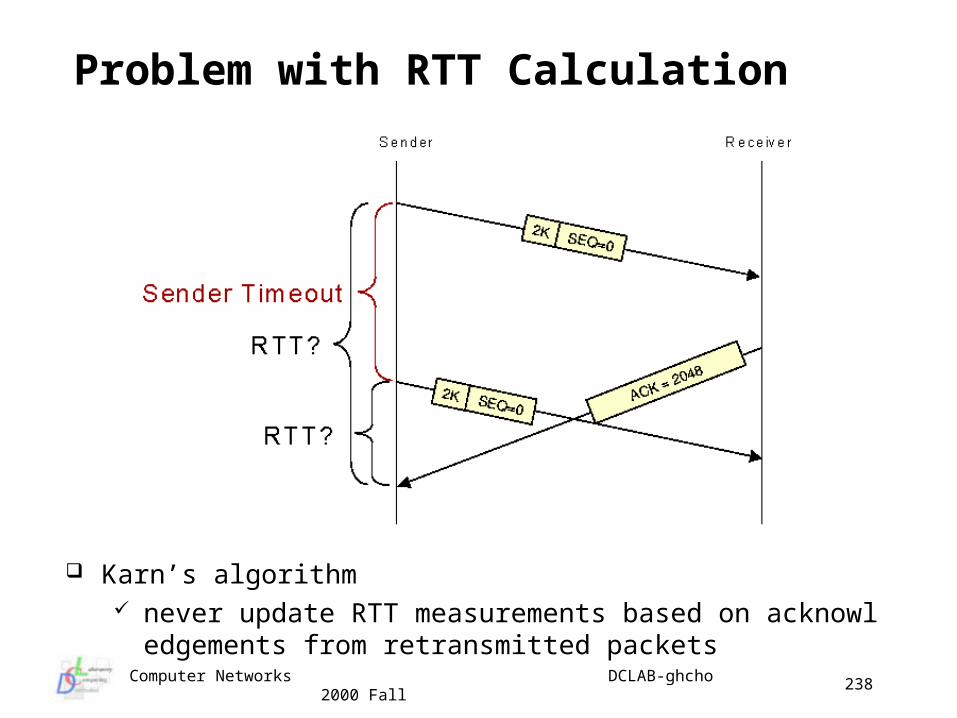
Computer Networks DCLAB-ghcho 2000 Fall
238
Problem with RTT Calculation
Karn’s algorithm never update RTT measurements based on acknowledgement
s from retransmitted packets
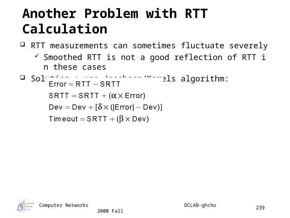
Computer Networks DCLAB-ghcho 2000 Fall
239
Another Problem with RTT Calculation
RTT measurements can sometimes fluctuate severely Smoothed RTT is not a good reflection of RTT in these cases
Solution : use Jacobson/Karels algorithm:
Computer Networks DCLAB-ghcho 2000 Fall
240
TCP Congestion Control (I)
Congestion control is based on the principle that no new packets can be allowed until the old one is going (law of conservation of packets) TCP achieve this by dynamically manipulating the window size
How do we detect congestion? Detect congestion is difficult
lost packets could be due noisy transmission line congested routers or switches
in WANs, frequent timeouts are typically caused by the existence of congestion
noisy channels (wireless) lead to timeouts congested routers, or lack of buffer space at receivers lead
to discarding incoming packets
Computer Networks DCLAB-ghcho 2000 Fall
241
TCP Congestion Control (II)
During connection establishment, you setup window size based on buffer size
Potential congestion causes are due to network capacity and receiver capacity
TCP maintain two windows Receiver Window(RW) - determined by buffer size Congestion Window(CW) - proportion to network capacity
Number of bytes that can be transmitted is the minimum of the receiver window and the congestion window
Examples if the RW says the sender can transmit 8K, but the CW is
only 4K, the the sender may only transmit 4K The TCP congestion control algorithm makes use of :
slow start congestion avoidance (linear increase thresholds)
Computer Networks DCLAB-ghcho 2000 Fall
242
TCP Congestion Algorithm (Slow Start) Sender initializes the congestion window to maximum segment size
and the receiver window to maximum buffer space TCP slow start
congestion window starts small, at 1 segment size each time a transmitted segment is acknowledged, the
congestion window is increased by one maximum segment size Congestion window keeps growing exponential until it becomes
equal to receiver window Packet losses indicate congestion
these are determined by using timers at the sender When a timeout occurs, the congestion window is reduced to one
maximum segment size and everything starts over this leads to low throughput
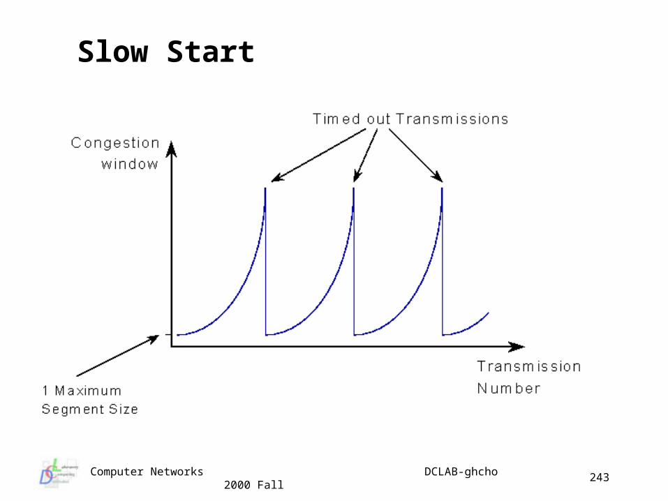
Computer Networks DCLAB-ghcho 2000 Fall
243
Slow Start
Computer Networks DCLAB-ghcho 2000 Fall
244
TCP Linear Increase Threshold (I) Establish a threshold at which the rate increase is linear instead of
exponential to improve efficiency Algorithm
start the threshold at 64K start the congestion window size at 1 segment size increase the congestion window size exponentially using slow
start until the threshold is reached once the threshold is passed only increase the congestion
window size by 1 segment size for each congestion window of data transmitted
if a timeout occurs, reset the congestion window size to 1 segment and set threshold to ½ of MIN (sliding window, congestion window)
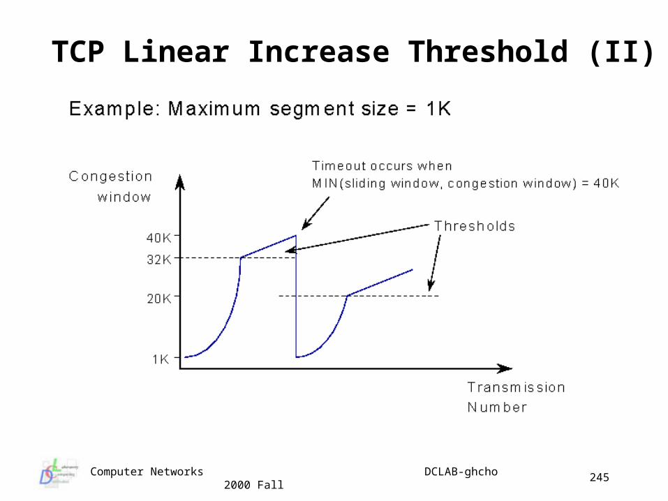
Computer Networks DCLAB-ghcho 2000 Fall
245
TCP Linear Increase Threshold (II)
Computer Networks DCLAB-ghcho 2000 Fall
246
UDP
UDP is an unreliable transport protocol UDP does not provide:
flow or error control connection management guaranteed in-order packet delivery
UDP is almost a “null” transport layer Why UDP?
no connection needs to be set up throughput may be higher because UDP packets are
easier to process, especially at the source the user doesn’t care if the data is transmitted reliably the user wants to implement his or her own transport
protocol
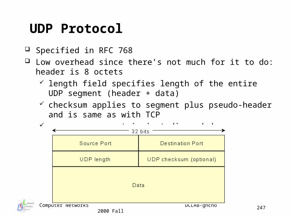
Computer Networks DCLAB-ghcho 2000 Fall
247
UDP Protocol
Specified in RFC 768 Low overhead since there’s not much for it to do: header is 8
octets length field specifies length of the entire UDP segment (header
+ data) checksum applies to segment plus pseudo-header and is same
as with TCP on error segment is just discarded


