Download - Configuration Check

8/13/2019 Configuration Check
http://slidepdf.com/reader/full/configuration-check 1/62
203233363.xlsx.ms_office 文档密级:
To ensure proper running of the radio network, configuration check must be conduct
so that the transmission network meets the conditions for site deployment. You can
referring to contents in the Scenarios sheet and then find the corresponding items t
This document describes the requirements for configuration parameters of transmiss
in the GBSS14.0 Abis and UMTS RAN14.0 Iub insecure IPRAN networking scenario
NEs should be conducted by transmission network engineers. In IPRAN networking,
transmission network through the Ethernet interface, and the BTS/NodeB can conne
multiplexing (TDM) interface or Ethernet interface. This document does not describe
networking between the BTS/NodeB and the BSC/RNC.
If configurations of the live network are different from those of the recommended sce
Design Department to determine the networking solution.
This document is intended for customer service engineers, operation engineers, and
Reference: RAN14.0 Iub&GBSS14.0 Abis IP Transmission Networking Solution Rec
from the Wireless Transmission Solution Design Department
Configuration Check Guide to IPRAN Tra
To ensure proper running of the radio network, configuration check must be conduct
so that the transmission network meets the conditions for site deployment. You can
referring to contents in the Scenarios sheet and then find the corresponding items t
This document describes the parameter configuration requirements for transmission
IPRAN networking scenario. The check on configurations between transmission
networking, the BSC/RNC is recommended to connect to the transmission network t
to the transmission network through time division multiplexing (TDM) or Ethernet. Thi
on end-to-end TDM networking between the BTS/NodeB and the BSC/RNC.
If configurations of the live network are different from those of the recommended sce
Design Department to determine the networking solution.
This document is intended for customer service engineers, operation engineers, and
Reference: RAN14.0 Iub&GBSS14.0 Abis IP Transmission Networking Solution Rec
from the Wireless Transmission Solution Design Department
Configuration Check Guide to IPRAN Tra
1/11/2014 华为机密,未经许可不得扩散 第1页,共62页
8/13/2019 Configuration Check
http://slidepdf.com/reader/full/configuration-check 2/62
203233363.xlsx.ms_office 文档密级:
ed on the transmission network before site deployment
confirm the transmission networking scenario by
o be checked.
ion NEs connecting to the BTS/NodeB and BSC/RNC
. The check on configurations between transmission
the BSC/RNC is recommended to connect to the
ct to the transmission network through the time division
the configuration check on end-to-end (E2E) TDM
narios, contact the Wireless Transmission Solution
R&D engineers participating in remote commissioning.
ommended for Commercial Networks by Yin Zhaogen
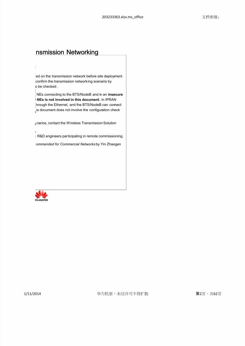
nsmission Networking
ed on the transmission network before site deployment
confirm the transmission networking scenario by
o be checked.
NEs connecting to the BTS/NodeB and in an insecure
NEs is not involved in this document. In IPRAN
hrough the Ethernet, and the BTS/NodeB can connect
is document does not involve the configuration check
narios, contact the Wireless Transmission Solution
R&D engineers participating in remote commissioning.
ommended for Commercial Networks by Yin Zhaogen
nsmission Networking
1/11/2014 华为机密,未经许可不得扩散 第2页,共62页

8/13/2019 Configuration Check
http://slidepdf.com/reader/full/configuration-check 3/62

8/13/2019 Configuration Check
http://slidepdf.com/reader/full/configuration-check 4/62
rotocol (PPP)/Multi-link PPP (MLPPP) port

8/13/2019 Configuration Check
http://slidepdf.com/reader/full/configuration-check 5/62
Interface type
MTU(Byte)MRU(Byte)
SPEED
Duplex
Flow control auto-negotiation
Port STP
LAG type
Number of trunks
Backup mode
Priorities of ports
Transmitting speed of HELLO
Recovery time
Port status (Active/Passive)
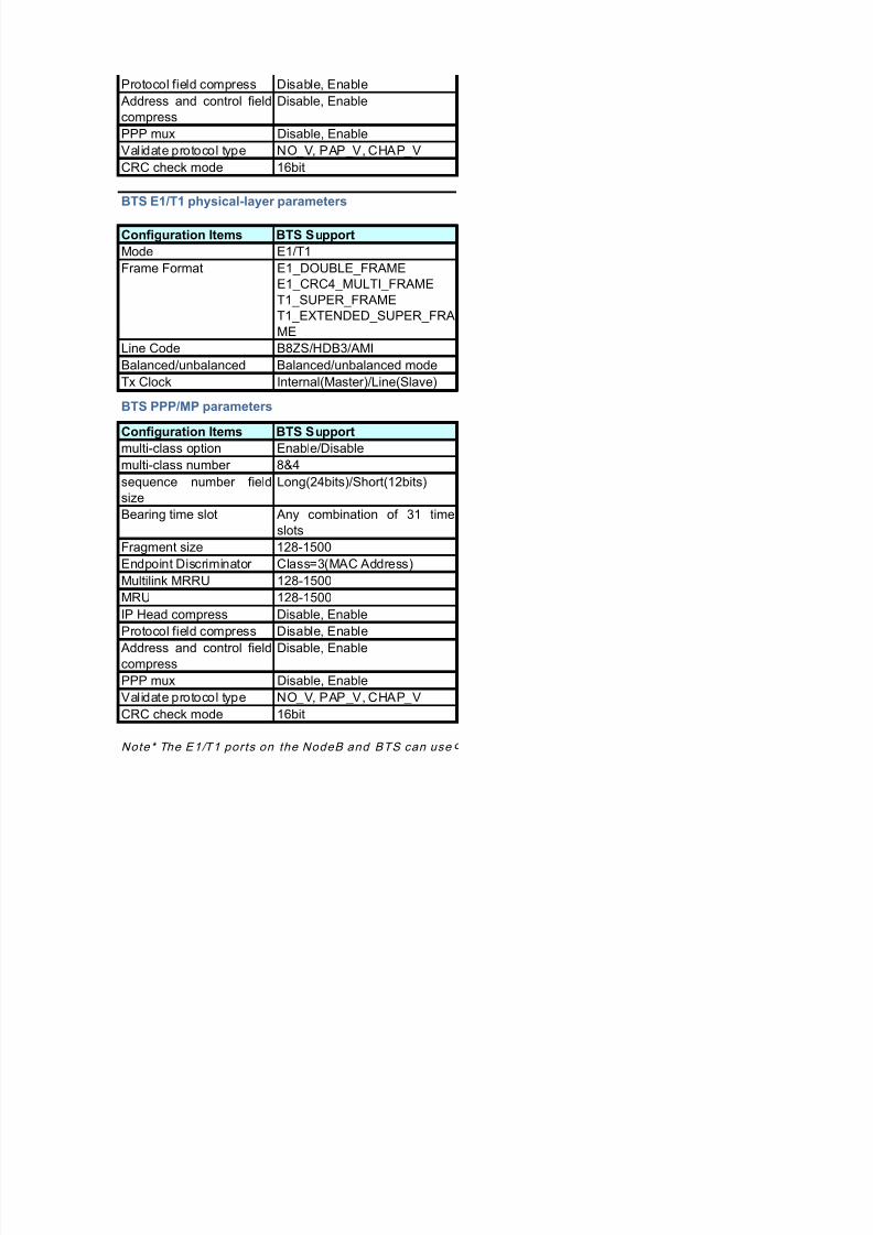
Configuration Items NodeB Support
Mode E1/T1E1_DOUBLE_FRAME
E1_CRC4_MULTI_FRAME
T1_SUPER_FRAME
T1_EXTENDED_SUPER_FRA
ME
Line Code B8ZS/HDB3/AMI
Balanced/unbalanced Balanced/unbalanced mode
Tx Clock Internal(Master)/Line(Slave)
Configuration Items NodeB Support
multi-class option Enable/Disable
multi-class number 8&4sequence number field
size
Long(24bits)/Short(12bits)
Bearing time slot Any combination of 31 time
slots
Fragment size 128-1500
Endpoint Discriminator Class=3(MAC Address)
Multilink MRRU 128-1500
MRU 128-1500
IP Head compress Disable, Enable
Parameter Type
IEEE802.3ad LAG
configuration
Physical-layer parameters
of the Ethernet interface
NodeB E1/T1 physical-layer parameters
NodeB PPP/MP parameters
Frame Format
8/13/2019 Configuration Check
http://slidepdf.com/reader/full/configuration-check 6/62
Protocol field compress Disable, Enable
Address and control field
compress
Disable, Enable
PPP mux Disable, Enable
Validate protocol type NO_V, PAP_V, CHAP_V
CRC check mode 16bit
Configuration Items BTS Support
Mode E1/T1
E1_DOUBLE_FRAME
E1_CRC4_MULTI_FRAME
T1_SUPER_FRAME
T1_EXTENDED_SUPER_FRA
ME
Line Code B8ZS/HDB3/AMI
Balanced/unbalanced Balanced/unbalanced mode
Tx Clock Internal(Master)/Line(Slave)
Configuration Items BTS Support
multi-class option Enable/Disable
multi-class number 8&4
sequence number field
size
Long(24bits)/Short(12bits)
Bearing time slot Any combination of 31 time
slots
Fragment size 128-1500
Endpoint Discriminator Class=3(MAC Address)
Multilink MRRU 128-1500
MRU 128-1500
IP Head compress Disable, Enable
Protocol field compress Disable, Enable
Address and control field
compress
Disable, Enable
PPP mux Disable, Enable
Validate protocol type NO_V, PAP_V, CHAP_V
CRC check mode 16bit
BTS PPP/MP parameters
Note* The E1/T1 ports on the NodeB and BTS can use
BTS E1/T1 physical-layer parameters
Frame Format
8/13/2019 Configuration Check
http://slidepdf.com/reader/full/configuration-check 7/62
Settings of Parameters of Huawei Devices on the
Physical Layer and Data Link Layer
10\100\1000BaseT, 100BaseX, 1000BaseX
46–1500
1500
100M/1000M/AUTO
FULL/AUTO
PAUSE
Not supported
Static
The BSC/RNC supports a maximum of eight trunks,
and the BTS/NodeB supports a maximum of two trunks.
1:1 active and standby
Different priorities for two ports of a BSC/RNC, with a
high priority for the port in the even-numbered slot;
different priorities for two ports of a BTS/NodeB
Fast
0 (immediate recovery)
Active
NodeB Default
E1
HDB3
Line(Slave)
NodeB Default
Enable
4
Long(24bits)
All 31 time slots selected
256
Class=3(MAC Address)
1500
1500
Enable
Depending on kinds of transmission media: unbalanced
E1_CRC4_MULTI_FRAME(Note1)

8/13/2019 Configuration Check
http://slidepdf.com/reader/full/configuration-check 8/62
Disable
Disable
Disable
NO_V
16bit
BTS Default
E1
HDB3
Line(Slave)
BTS Default
Enable
4
Long(24bits)
All 31 time slots selected
256
Class=3(MAC Address)
1500
1500
Enable
Disable
Disable
Disable
NO_V
16bit
nly part of t imeslots. For scenar ios where only part
Depending on kinds of transmission media: unbalanced
E1_CRC4_MULTI_FRAME(Note1)
8/13/2019 Configuration Check
http://slidepdf.com/reader/full/configuration-check 9/62
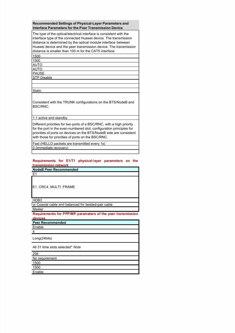
Recommended Settings of Physical-Layer Parameters and
Interface Parameters for the Peer Transmission Device
The type of the optical/electrical interface is consistent with the
interface type of the connected Huawei device. The transmission
distance is determined by the optical module interface between
Huawei device and the peer transmission device. The transmission
distance is smaller than 100 m for the CAT5 interface.
15001500
AUTO
AUTO
PAUSE
STP Disable
Static
Consistent with the TRUNK configurations on the BTS/NodeB and
BSC/RNC.
1:1 active and standby
Different priorities for two ports of a BSC/RNC, with a high priority
for the port in the even-numbered slot; configuration principles for
priorities of ports on devices on the BTS/NodeB side are consistent
with those for priorities of ports on the BSC/RNC.
Fast (HELLO packets are transmitted every 1s)
0 (immediate recovery)
Requirements for E1/T1 physical-layer parameters on the
transmission network
NodeB Peer Recommended
E1
HDB3
Master
Requirements for PPP/MP parameters of the peer transmission
devices
Peer Recommended
Enable
4
Long(24bits)
All 31 time slots selected* Note
256
No requirement
1500
1500
Enable
or Coaxial cable and balanced for twisted-pair cable
E1_CRC4_MULTI_FRAME

8/13/2019 Configuration Check
http://slidepdf.com/reader/full/configuration-check 10/62
Disable
Disable
Disable
NO_V
16bit
Requirements for E1/T1 physical-layer parameters on the
transmission network
BTS Peer Recommended
E1
HDB3
(Note2)
Requirements for PPP/MP parameters of the peer transmission
devices
Peer Recommended
Enable
4
Long(24bits)
All 31 time slots selected* Note
256
No requirement
1500
1500
Enable
Disable
Disable
Disable
NO_V
16bit
f t imeslots are used, conf i rmed with Huawei R&D engineers.
or Coaxial cable and balanced for twisted-pair cable
E1_CRC4_MULTI_FRAME
8/13/2019 Configuration Check
http://slidepdf.com/reader/full/configuration-check 11/62
203233363.xlsx.ms_office 文档密级:
1
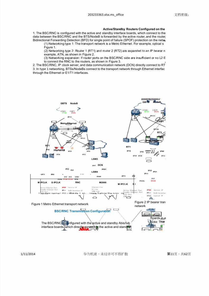
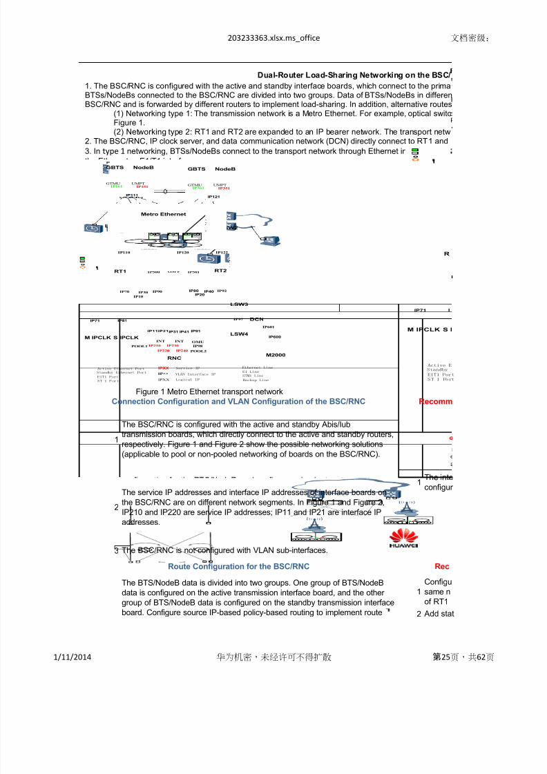
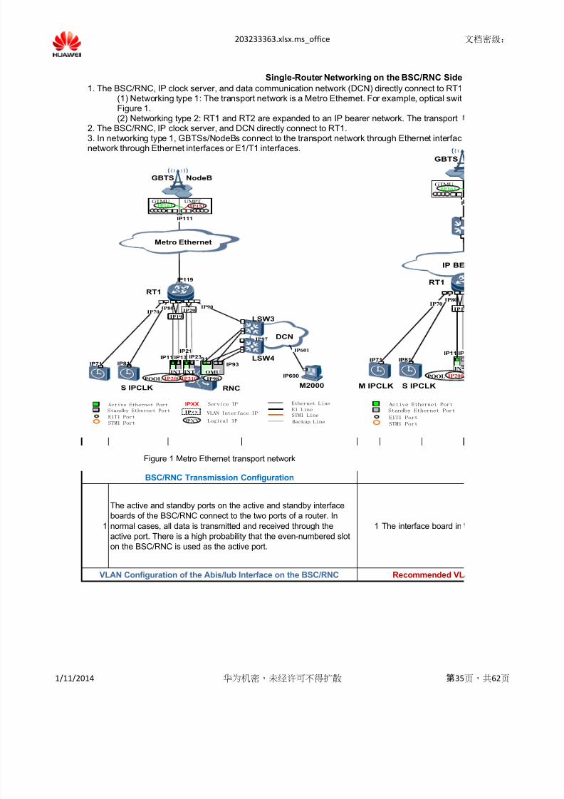
Figure 1 Metro Ethernet transport network
The BSC/RNC is configured with the active and standby Abis/Iub
interface boards, which directly connect to the active and standby
Boards in e
Note: Ther
port.
BSC/RNC Transmission Configuration
Figure 2 IP bearer tran
network
Active/Standby Routers Configured on the
1. The BSC/RNC is configured with the active and standby interface boards, which connect to thedata between the BSC/RNC and the BTS/NodeB is forwarded by the active router, and the routerBidirectional Forwarding Detection (BFD) for single point of failure (SPOF) protection on the netw
(1) Networking type 1: The transport network is a Metro Ethernet. For example, optical sFigure 1.
(2) Networking type 2: Router 1 (RT1) and router 2 (RT2) are expanded to an IP bearer nexample, ATN, as shown in Figure 2.(3) Networking expansion: If router ports on the BSC/RNC side are insufficient or no L2 Eto connect the RNC to the routers, as shown in Figure 3.
2. The BSC/RNC, IP clock server, and data communication network (DCN) directly connect to RT
3. In type 1 networking, BTSs/NodeBs connect to the transport network through Ethernet interfac
through the Ethernet or E1/T1 interfaces.
Metro Ethernet
LSW1
VRRP3
IP119
IP110 IP112
IP10
RNC
RT1 RT2
VRRP1 & 2
IP19
IP13
IP200
IP70
M IPCLK
IP71
S IPCLK
IP81
IP80
M2000
IP601
LSW3
IP98
V R R P 4
I P 9
9IP12
IP91
INT OMU
LSW4
DCN
IP90IP92
IP97
IP600
IP93
IP11
IP210
INT
IP21IP23
IP22IP20
IP29
POOL
IPXXActive Ethernet Port
Standby Ethernet Port
Service IP Ethernet Line
E1 LineVLAN Interface IP
IPXX
IP××
Logical IPE1T1 Port
STM1 Port Backup Line
STM1 Line
NodeBGBTS
GTM U UMP TIP161 IP151
IP111
IP10
RNC
RT1
VRRP1 & 2
IP19
IP13
IP200
IP119
LSW1
IP70
M IPCLK
IP71
S IPCLK
IP81
IP80
IP98
V R R P 4
I P 9 9
IP12
IP91
INT OMU
IP90
IP BEARER
RT3
IP
IP11
IP210
INT
IP21IP23
IP20
IP29
POOL
IPXXActive Ethernet Port
Standby Ethernet Port
Service IP
VLAN Interfac
IPXX
IP××
Logical IPE1T1 Port
STM1 Port
NodeBGBTS
GTMU UM PTIP161 IP151
IP111
1/11/2014 华为机密,未经许可不得扩散 第11页,共62页
8/13/2019 Configuration Check
http://slidepdf.com/reader/full/configuration-check 12/62
203233363.xlsx.ms_office 文档密级:
2
3
4
1 1
2 2
1 1
2 2
3The conditions for switchover between the active and standby
boards on the BSC/RNC are as follows:
If no VLAN sub-interface is configured for the BSC/RNC, do not
configure the VLAN ID.
If a VLAN sub-interface is configured for the BSC/RNC, configure
the VLAN ID.
When no
(1) If the r
BSC/RNC t
same as th
(2) If no V
router conn
If a VLAN s
BSC/RNC t
the BSC/R
.
networking solutions (applicable to pooled or non-pooled
networking of boards on the BSC/RNC). VRRP (VR
RT2 conne
In Figure 1
(1) The porrouters) tha
must share
(2) An L2 E
50% of the
(3) VRRP1
In Figure 3,
(1) Type 1:
(2) Type 2:
transmitted
2
If router ports are insufficient or the routers do not support the L2
port configuration, the BSC/RNC connects to the active and
standby routers by using the LSW. Figure 3 shows the networking
diagram.
Recom
The active
IP address
VLAN Configuration of the Abis/Iub Interface on the BSC/RNC
If the BTS/
RT1 and R
heartbeat
Route Configuration for the BSC/RNC
In the pooled networking scenario, configure source IP-based
policy-based routing to implement route configuration for the
BTS/NodeB, and add static routes from the BSC/RNC to the
M2000.
In the non-pooled networking scenario, add static routes from the
BSC/RNC to the M2000 and BTSs/NodeBs. The next hop is the
virtual IP address of VRRP1 port on RT1 and RT2.
To ensure t
must be hi
1/11/2014 华为机密,未经许可不得扩散 第12页,共62页
8/13/2019 Configuration Check
http://slidepdf.com/reader/full/configuration-check 13/62
203233363.xlsx.ms_office 文档密级:
4
5
6
1 1
2 2
3 3
1
2
1
2
,
the active port on the BSC/RNC initiates two BFD sessions to
detect interface IP addresses of the routers. If two BFD sessions
on the active port detect faults, the standby port initiates one
Address Resolution Protocol (ARP) detection session to detect the
virtual IP address of VRRP (see note 1).
(2) If the routers do not support BFD, ARP detections are initiated
on both the active and standby ports of the BSC/RNC. The ARPdetection duration on the active port must be longer than that on
the standby port. Otherwise, invalid switchovers may occur.
1
The master and slave clock servers are configured. They directly
connect to the active and standby routers RT1 and RT2 to
implement redundancy protection. The VLAN is not configured.
Range of Reserved IP Addresses for the BSC/RNC
3
The router
Each virtua
seconds.
Detection p
3
Echo: Disable
Asynchron
1The IP add
BSC/RNC.1192.168.0.0/16 (configurable)
The BTS/NodeB obtains clock signals from the IP clock server
using 1588v2 unicast packets by default.
Clock Server Configuration
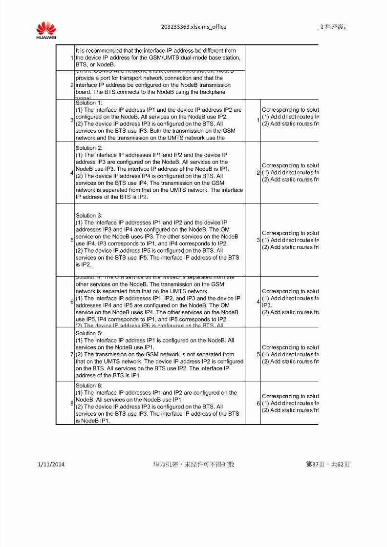
On the GSM/UMTS network, it is recommended that the NodeB
provides a port for transport network connection and that the
interface IP address be configured on a NodeB transmission board.
The BTS connects to the NodeB through the backplane tunnel.
(1) The interface IP address IP1 and the device IP address IP2 are
configured on the NodeB. All services on the NodeB use IP2.
(2) The device IP address IP3 is configured on the BTS. All
services on the BTS use IP3. Both the transmission on the GSMnetwork and the transmission on the UMTS network use the
interface IP address IP1.
IP Address Configuration for the Ethernet Interface on the
BTS/NodeB
It is rcommended that the interface IP address be different from the
device IP address for the GSM/UMTS dual-mode base station,
BTS, or NodeB.
Correspon
(1) Add dir
(2) Add sta
Configure1
Authentication mode: Authentication not supported Echo: Disa
BFD Configuration on the BSC/RNC
Default detection period: 100 ms
In IP beare
is sent to th
1/11/2014 华为机密,未经许可不得扩散 第13页,共62页

8/13/2019 Configuration Check
http://slidepdf.com/reader/full/configuration-check 14/62
203233363.xlsx.ms_office 文档密级:
4 2
8 6
9 7
8
other services on the NodeB. The transmission on the GSM
network is separated from that on the UMTS network.
(1) The interface IP addresses IP1, IP2, and IP3 and the device IPaddresses IP4 and IP5 are configured on the NodeB. The O&M
service on the NodeB uses IP4. The other services on the NodeB
use IP5. IP4 corresponds to IP1, and IP5 corresponds to IP2.
(1) The interface IP addresses IP1 and IP2 and the device IP
addresses IP3 and IP4 are configured on the NodeB. The OM
service on the NodeB uses IP3. The other services on the NodeB
use IP4. IP3 corresponds to IP1, and IP4 corresponds to IP2.
(2) The device IP address IP5 is configured on the BTS. All
services on the BTS use IP5. The interface IP address of the BTS
is IP2.
Solution 5:
(1) The interface IP address IP1 is configured on the NodeB. All
services on the NodeB use IP1.
(2) The transmission on the GSM network is not separated from
that on the UMTS network. The device IP address IP2 is configured
on the BTS. All services on the BTS use IP2. The interface IP
address of the BTS is IP1.
Solution 6:
(1) The interface IP addresses IP1 and IP2 are configured on theNodeB. All services on the NodeB use IP1.
(2) The device IP address IP3 is configured on the BTS. All
services on the BTS use IP3. The interface IP address of the BTS
is NodeB IP1.
Correspon
(1) Add dir
(2) Add sta
Correspon
(1) Add dir
(2) Add sta
IP5.
Correspon
(1) Add dir
(2) Add sta
Correspon
(1) Add dir
(2) Add sta
Correspon
(1) Add dir
NodeB IP3.
(2) Add sta
5
6
7
Solution 2:
(1) The interface IP addresses IP1 and IP2 and the device IP
address IP3 are configured on the NodeB. All services on the
NodeB use IP3. The interface IP address of the NodeB is IP1.
(2) The device IP address IP4 is configured on the BTS. All
services on the BTS use IP4. The transmission on the GSM
network is separated from that on the UMTS network. The interface
IP address of the BTS is IP2.
10
Solution 8:
(1) The interface IP addresses IP1, IP2, and IP3 and the device IP
addresses IP4 and IP5 are configured on the NodeB. IP4, which is
on the same network segment as IP1, is used by the OM service.
The other services on the NodeB use IP5. The interface IP address
of the NodeB is IP2.
Solution 7:
(1) The interface IP addresses IP1 and IP2 and the device IP
address IP3 are configured on the NodeB. IP3 is on the same
network segment as IP1. All services on the NodeB use IP3.
(2) The transmission on the GSM network is not separated from
that on the UMTS network. The device IP address IP4 is configured
on the BTS. All services on the BTS use IP4. The interface IP
address of the BTS is IP2.
Correspon
(1) Add dir
IP3, and N
(2) Add sta
3
Correspon
(1) Add dir
NodeB IP3.(2) Add sta
IP6.
4
5
1/11/2014 华为机密,未经许可不得扩散 第14页,共62页

8/13/2019 Configuration Check
http://slidepdf.com/reader/full/configuration-check 15/62
203233363.xlsx.ms_office 文档密级:
9
1
2
2 3
3 4
1
2
3
4
5
3
4
2
The BTS/NodeB obtains the IP address of the PPP interface from
the gateway during the IPCP negotiation.
Add the ro
address an
The BTS is configured with a device IP address, which is used by
all services. The outbound interface of the BTS is NodeB PPP/MP
interface.
-
2
The ARP agent is not configured for the BTS/NodeB.
Reserved IP Addresses for the BTS/NodeB
Configuration for Remote BTS/NodeB Deployment
t e
route from
the BTS/N
IP address
addresses1
If another r
(1) If the B
VRRP 2 in
(2) Ensure
RT2 so tha
If routes to
6
The BTS/NodeB sends DHCP broadcast packets, attempting to
obtain the IP address and M2000 configurations (including the E1
interface configuration).
VLAN Configurations of the Ethernet Interface on the BTS/NodeB
You are recommended to configure VLANs for the BTS/NodeB,
one VLAN for each interface.
IP Address Configuration for the E1/T1 Interface on the BTS/NodeB IP F
1
If the NodeB uses the E1/T1 interface, the GSM/UMTS network
technology is not supported. The O&M service on the NodeB is
separated from the other services on the NodeB.The router
Multilink Pr
Protocol (I1
The DHCP
forwarded.
Dynamic
1
1 10.22.1.0/24
If multiple
BTS/Node
allowed by
If the BTS/
In Metro Et
router. You
and after th
If one VLA
work in acc
(2) The transmission on the GSM network is separated from that on
the UMTS network. The device IP address IP6 is configured on the
BTS. All services on the BTS use IP6. The interface IP address of
the BTS is IP3.
You are advised not to configure VLANs for the BTS/NodeB by
service flow type.
the next-ho
(1) If VRR
IP address
(2) If the ro
1
1/11/2014 华为机密,未经许可不得扩散 第15页,共62页

8/13/2019 Configuration Check
http://slidepdf.com/reader/full/configuration-check 16/62
203233363.xlsx.ms_office 文档密级:
2
3
1
2
3
Note1*
Note2
*
Note3
*
If the durati
primary ancaused by
radio servi
interruption
The VRRP
The priorities of static routes are effective on only the routers where the static routes are co
no routing policy is configured, the route between RT1 and the BSC/RNC is equivalent as t
priority may not be used as the primary router.
The route configurations are the same on all interface boards of the BSC/RNC. The Media
board. After the switchover between the active and standby boards, the router updates the
hop interface IP address changes. When the active port is running, the standby port periodi
address to check transmission connectivity (the detection period is 30s).
a dynamic
System (IS
(1) Introdu
the BTS/N
(2) Configu
BFD2 that i
be quickly(3) Introdu
priority is th
1
VRRP preemption delay: The VRRP convergence is faster than the OSPF convergence. If
service data is interrupted due to lack of routes. Therefore, a preemption delay (for exampl
duration is within 3 seconds, and the OSPF convergence duration is about 4 seconds. The
Preemption delay must not be configured on the secondary router. Otherwise, the service i
VRRP trac
If no router
the LSW1
ports), the
1/11/2014 华为机密,未经许可不得扩散 第16页,共62页

8/13/2019 Configuration Check
http://slidepdf.com/reader/full/configuration-check 17/62
203233363.xlsx.ms_office 文档密级:
Note4
*
VRRP must be configured on RT2 (VRRP secondary router) to track the BFD session betw
becomes primary. The detection period can be shortened to a minimum of 30 ms. The defa
the carrier-grade requirements.
1/11/2014 华为机密,未经许可不得扩散 第17页,共62页
8/13/2019 Configuration Check
http://slidepdf.com/reader/full/configuration-check 18/62
203233363.xlsx.ms_office 文档密级:
ven-numbered slots on the BSC/RNC connect to routers with a higher priority.
is a high probability that the even-numbered slot on the BSC/RNC is used as the active
Recommended Router Configuration
Figure 3 Network where the RNC connects to routers using the LSW sport
BSC/RNC Side
active and standby routers on the transport network respectively. Normally,s are configured with Virtual Router Redundancy Protocol (VRRP) andork.itch node (OSN) and virtual private LAN service (VPLS) network, as shown in
etwork. The transport network is an end-to-end (E2E) IP bearer network, for
thernet trunk link is provided between the routers, use the LAN switch (LSW)
1 and RT2.
es. In type 2 networking, BTSs/NodeBs can connect to the transport network
IP10
RT1 RT2
VRRPIP19
LSW1 LSW2
RNC
Type 2: The RNC connects to the routers after
converged at LSWs. VRRP heartbeat messages are
transmitted by using the channel between the routers.
IP11 IP13
IP12
IP10
RT1 RT2
VRRPIP19
1 LSW2
RNC
IP11 IP13
IP12
Type 1: The RNC connects to the routers after
converged at LSWs. VRRP heartbeat messages are
transmitted by using the L2 port between the routers.
RT2
M2000
IP601
LSW3
LSW4
DCN
IP92
IP97
IP600
93
IP22
Ethernet Line
E1 Line e IP
Backup Line
STM1 Line
1/11/2014 华为机密,未经许可不得扩散 第18页,共62页

8/13/2019 Configuration Check
http://slidepdf.com/reader/full/configuration-check 19/62
203233363.xlsx.ms_office 文档密级:
LAN sub-interface is configured for the BSC/RNC:
uter needs to be configured with a VLAN sub-interface and the port connecting the
o the LSW or router works in access VLAN mode, the PVID configuration should be the
e VLAN sub-interface configuration of the router.
AN sub-interface is configured for the router, the VLAN is not configured for the LSW or
ecting to the BSC/RNC.
ub-interface is configured for the BSC/RNC, configure the LSW or router connecting to the
o work in VLAN TRUNK mode and set the VLAN ID of the LSW or router to the VLAN ID of
C (setting the PVID to an idle VLAN ID).
ecommended Route Configuration for Routers on the BSC/RNC Side
P1 in the figure) is configured for interfaces on the active and standby routers RT1 and
cting to the BSC/RNC.
and Figure 2, the BSC/RNC directly connects to routers.
ts on RT1 and RT2 (ports connecting the routers to the BSC/RNC and the port between thet are involved in VRRP1 must be configured with L2 mode and VLAN sub-interfaces and
the same VLAN.
thernet trunk is configured between RT1 and RT2. The bandwidth of the trunk is larger than
total traffic on the BSC/RNC. The trunk uses at least two GE ports for convergence.
heartbeat messages are transmitted by using the L2 Ethernet trunk between the routers.
the BSC/RNC connects to routers by using LSWs.
The router configurations are the same as those in Figure 1 and Figure 2.
The L2 mode is not configured for router ports, and VRRP1 heartbeat messages are
between LSW1 and LSW2.
ended VLAN Configuration for the Transport Network on the BSC/RNC Side
and standby routers on the transport network are added to the static route entries for device
s of the BSC/RNC. The next hop is the IP address of the active interface on the BSC/RNC.
odeB O&M channel does not pass through the BSC/RNC, configure direct routes from
2 to the M2000 and VRRP (For example, VRRP4 in Figure 1 and Figure 2). VRRP4
essages are transmitted using the LSW (for example, LSW3 and LSW4) on the DCN.
hat RT1 serves as the primary router, priorities of VRRP1 and VRRP4 configured for RT1
her than those of VRRP1 and VRRP4 configured for RT2.
1/11/2014 华为机密,未经许可不得扩散 第19页,共62页

8/13/2019 Configuration Check
http://slidepdf.com/reader/full/configuration-check 20/62
203233363.xlsx.ms_office 文档密级:
Recommended BFD Configuration on Routers
Required Reserved IP Addresses on the Transmission Network
Recommended Route Configuration on the BTS/NodeB
must update the ARP entry after receiving the gratuitous ARP.
l IP address of VRRP can timely respond to ARP REQUEST messages sent every 10
eriod: 100 ms
us mode, passive end
resses used by the transport network cannot conflict with the reserved IP addresses for the
Recommended Clock Server Configuration on Routers
ing to solution 1:
ct routes from the BTS, NodeB, gateway, and routers to NodeB IP1.
ic routes from the BTS, NodeB, gateway, and routers to BTS IP3 and NodeB IP2.
irect routes from the active and standby routers to the master and slave clock servers.
le
r networking, a route policy or active/standby route planes must be configured so that data
e BSC/RNC using RT1.
1/11/2014 华为机密,未经许可不得扩散 第20页,共62页

8/13/2019 Configuration Check
http://slidepdf.com/reader/full/configuration-check 21/62
203233363.xlsx.ms_office 文档密级:
ing to solution 2:
ct routes from the BTS, NodeB, gateway, and routers to NodeB IP1 and NodeB IP2.
ic routes from the BTS, NodeB, gateway, and routers to NodeB IP3 and BTS IP4.
ing to solution 3:
ct routes from the BTS, NodeB, gateway, and routers to NodeB IP1 and NodeB IP2.
ic routes from the BTS, NodeB, gateway, and routers to NodeB IP3, NodeB IP4, and BTS
ing to solution 5:
ct routes from the BTS, NodeB, gateway, and routers to NodeB IP1.
ic routes from the BTS, NodeB, gateway, and routers to BTS IP2.
ing to solution 6:
ct routes from the BTS, NodeB, gateway, and routers to NodeB IP1 and NodeB IP2.
ic routes from the BTS, NodeB, gateway, and routers to BTS IP3.
ing to solution 7:
ct routes from the BTS, NodeB, gateway, and routers to NodeB IP1, NodeB IP2, and
ic routes from the BTS, NodeB, gateway, and routers to BTS IP4.
ing to solution 8:
ct routes from the BTS, NodeB, gateway, and routers to NodeB IP1, NodeB IP2, NodeB
deB IP4.
ic routes from the BTS, NodeB, gateway, and routers to NodeB IP5 and BTS IP6.
ing to solution 4:
ct routes from the BTS, NodeB, gateway, and routers to NodeB IP1, NodeB IP2, and
ic routes from the BTS, NodeB, gateway, and routers to NodeB IP4, NodeB IP5, and BTS
1/11/2014 华为机密,未经许可不得扩散 第21页,共62页
8/13/2019 Configuration Check
http://slidepdf.com/reader/full/configuration-check 22/62
203233363.xlsx.ms_office 文档密级:
tes to the E1/T1 interface of the BTS/NodeB: All PPP/MP links can use the same device IP
d share a large network segment on the router side.
Required Reserved IP Addresses on the Transmission Network
a ress s erent rom t e nter ace a ress on t e o e , con gure t e ost
T3 (RT3 connects to the BTS/NodeB through the E1 interface) to the O&M IP address of
deB.
s of all interfaces and sub-interfaces on routers cannot conflict with the reserved IP
or the BTS/NodeB: 10.22.1.0/24.
uter exists between RT1 and RT2 or the transmission bearer network is IP bearer network
S/NodeB is configured with two routers (see Figure 1), configure VRRP (for example,
Figure 1) on the interfaces of the routers connecting to the BTS/NodeB.
that the priority of VRRP2 configured on RT1 is higher than that of VRRP2 configured on
RT1 serves as the primary router.
the BTS exist, you need to add the static routes to the BTS.
Recommended VLAN Configurations on the Transmission Network
nctions of the E1/T1 Interface Connecting the BTS/NodeB with the Router
(RT3) supports the function of assigning the interface IP address for the BTS/NodeB on the
otocol (MP)/Point-to-Point Protocol (PPP) interface through Internet Protocol Control
CP).
Relay is required to relay only DHCP broadcast packets. DHCP unicast packets are directly
Host Configuration Protocol (DHCP) Relay of Routers on the BTS/NodeB Side
LANs are configured for the BTS/NodeB, set the LSW that directly connects to the
to work in VLAN TRUNK mode, add VLAN IDs of the BTS/NodeB to the list of VLAN IDs
the port, and set the PVID to an idle VLAN ID.
odeB directly connects to routers, no VLAN is configured for router interfaces.
hernet networking, the VLAN ID conversion is allowed between the BTS/NodeB and the
must ensure that the VLAN ID of the BTS/NodeB maps the VLAN ID of the router before
e conversion.
is configured for the BTS/NodeB, set the LSW that directly connects to the BTS/NodeB to
ess mode and set the PVID to be consistent with the VLAN ID of the BTS/NodeB.
Route Configuration Between Routers
- - ,
p router of the BTS/NodeB.
is configured for the next-hop gateway, the DHCP Relay must be configured at the virtual
of VRRP.
uter connects to the E1 interface of the BTS/NodeB, the DHCP Relay must be configured
1/11/2014 华为机密,未经许可不得扩散 第22页,共62页
8/13/2019 Configuration Check
http://slidepdf.com/reader/full/configuration-check 23/62
203233363.xlsx.ms_office 文档密级:
on of route convergence on the intermediate network caused by the switchover between the
secondary routes to the BSC on RT1/RT2 is larger than 3s, the duration of switchoverhe route fault on the BSC side is larger than 3s. This does not meet the requirements of
es. You can configure BFD for IP fast reroute (FRR) on RT1/RT2 to enable the service
time during the switchover to be reduced to several milliseconds.
policy must ensure that the router of a lower priority immediately performs preemption.
nfigured and cannot be transmitted to other routers by using the dynamic route protocol. If
e route between RT2 and the BSC/RNC from the RT3 perspective. The router of a higher
ccess Control (MAC) address of the active board is different from that of the standby
RP entry after receiving the gratuitous ARP. The MAC address corresponding to the next-
cally performs the ARP detection on the virtual IP address of VRRP1 based on another IP
,
oute protocol (Open Shortest Path First (OSPF) or Intermediate System to Intermediate
IS)) must be configured between routers.
e the dynamic route protocol to the direct and static routes to the BSC/RNC and routers on
deB side.
re BFD1 that is bound to the static route from RT1 to the BSC/RNC on RT1, and configure
s bound to the static route from RT2 to the BSC/RNC on RT2 so that the route status can
pread to other routers and the BTS/NodeB uplink data is sent to the destination router. e the route priority policy into the dynamic route protocol to ensure that the route of a higher
e primary transmission path. (see note 2)
he VRRP preempts the primary router immediately after the primary router restarts, the
, 10 seconds) must be configured on the VRRP primary router. The VRRP convergence
secondary router is configured to work in immediate preemption mode by default.
terruption duration is increased.
s BFD sessions (see note 4).
VRRP Policy Configuration on the Router
exists between RT1 and RT2 and the routers are configured with VRRP1 to track links on
ide (or the routers are configured with VRRP2 and interconnect with the active and standby
ynamic or static route protocol does not need to be configured between RT1 and RT2.
1/11/2014 华为机密,未经许可不得扩散 第23页,共62页

8/13/2019 Configuration Check
http://slidepdf.com/reader/full/configuration-check 24/62
203233363.xlsx.ms_office 文档密级:
en the routers. If the BFD session detects faults, the secondary router is switched over and
ult VRRP detection period is 3 seconds (1 second x 3 = 3 seconds), which does not meet
1/11/2014 华为机密,未经许可不得扩散 第24页,共62页
8/13/2019 Configuration Check
http://slidepdf.com/reader/full/configuration-check 25/62
203233363.xlsx.ms_office 文档密级:
1
3
2
Figure 1 Metro Ethernet transport network
Add stat
Configu
same n
of RT1
Recomm
1
1
The inte
configur
2
Route Configuration for the BSC/RNC
The BSC/RNC is configured with the active and standby Abis/Iub
transmission boards, which directly connect to the active and standby routers,
respectively. Figure 1 and Figure 2 show the possible networking solutions
(applicable to pool or non-pooled networking of boards on the BSC/RNC).
The service IP addresses and interface IP addresses of interface boards on
the BSC/RNC are on different network segments. In Figure 1 and Figure 2,
IP210 and IP220 are service IP addresses; IP11 and IP21 are interface IP
addresses.
The BSC/RNC is not configured with VLAN sub-interfaces.
The BTS/NodeB data is divided into two groups. One group of BTS/NodeB
data is configured on the active transmission interface board, and the other
group of BTS/NodeB data is configured on the standby transmission interface
board. Configure source IP-based policy-based routing to implement route
Rec
Connection Configuration and VLAN Configuration of the BSC/RNC
Dual-Router Load-Sharing Networking on the BSC/
1. The BSC/RNC is configured with the active and standby interface boards, which connect to the primaBTSs/NodeBs connected to the BSC/RNC are divided into two groups. Data of BTSs/NodeBs in differenBSC/RNC and is forwarded by different routers to implement load-sharing. In addition, alternative routes
(1) Networking type 1: The transmission network is a Metro Ethernet. For example, optical switcFigure 1.
(2) Networking type 2: RT1 and RT2 are expanded to an IP bearer network. The transport netw2. The BSC/RNC, IP clock server, and data communication network (DCN) directly connect to RT1 and
3. In type 1 networking, BTSs/NodeBs connect to the transport network through Ethernet interfaces. In tthe Ethernet or E1/T1 interfaces.
LSW1LSW2
VRRP1
IP119
VRRP2
IP129
IP500 IP501OSPF
IP110 IP112 IP120 IP122
Metro Ethernet
RNC
RT2RT1
INT
IP70
M IPCLK
IP71
S IPCLK
IP81
M2000
IP600
LSW3
IP91
OMU
LSW4
DCN
IP90 IP92
IP11IP21
IP20
IP80
IP97
IP601
INT
IP41
IP10
IP30
IP31
IP40
IPXXActive Ethernet Port
Standby Ethernet Port
Service IP Ethernet Line
E1 LineVLAN Interface IP
IPXX
IP××
Logical IPE1T1 Port
ST 1 Port Backup Line
STM1 Line
IP210
IP220
IP98IP230
IP240
POOL1
POOL2
NodeBGBTS
GTMU UMPTIP161 IP151
IP111
NodeBGBTS
GTMU UMPTIP361 IP351
IP121
R
I
M IPCLK
IP71
S I
I
Active E
Standby
E1T1 Port
ST 1 Port
1/11/2014 华为机密,未经许可不得扩散 第25页,共62页

8/13/2019 Configuration Check
http://slidepdf.com/reader/full/configuration-check 26/62
203233363.xlsx.ms_office 文档密级:
1 1
2 2
3 3
1 1
2
1
2
Asynchr
Detectio
3
Echo: D
The interface IP address is recommended to be different from the device IPaddress for the GSM/UMTS dual-mode base station, BTS, or NodeB.
Configu
and Fig
(1) The
configur
routes f
the next
(2) The
configur
routes f
the next
The BF
the RT1
RT2, th
After de
the rout
forward
4
5
Default detection period: 100 ms
Echo: Disable
Authentication mode: Authentication not supportedRange of Reserved IP Addresses for the BSC/RNC R
Configu
clock se
On the GSM/UMTS network, it is recommended that the NodeB provides the
outbound transmission interface, that the interface IP address is configured
on the NodeB transmission board, and that the BTS connects to the NodeB
using the backplane tunnel.
o u on :
1 1The IP
address
configuration for the BTS/NodeB, and configure redundant routes.
The route configuration in the non-pooled networking scenario is as follows:
(1) The high-priority routes for the data with the destination IP address of
IP151 are configured on the active transmission interface board, and the next-
hop IP address of the route is IP10. The low-priority routes for the data with
the destination IP address of IP151 are configured on the standby
transmission interface board, and the next-hop IP address of the route is
IP20.(2) The high-priority routes for the data with the destination IP address of
IP111 are configured on the standby transmission interface board, and the
next-hop IP address of the route is IP20. The low-priority routes for the data
with the destination IP address of IP111 are configured on the active
transmission interface board, and next-hop IP address of the route is IP10.
In the pooled networking scenario, the primary and secondary routes are
configured on the basis of the source IP address.
The conditions for switchover between the active and standby boards on the
BSC/RNC are as follows:
(1) The Bidirectional Forwarding Detection (BFD) is enabled on the active and
standby transmission interface boards of the BSC/RNC and the routers
directly connect to the boards. If the BFD detects faults on a board, the
BSC/RNC deactivates all routes configured on the board and uses thesecondary route.
(2) If the routers do not support BFD, the primary/secondary route switchover
based on the physical port status is recommended to be configured for the
BSC/RNC.
(3) The Address Resolution Protocol (ARP) detection cannot be used by the
route switchover on the RT1/RT2 and cannot ensure reliability. Therefore, the
ARP detection is not recommended to be configured on the BSC/RNC.
BFD Configuration on the BSC/RNC
2
1
192.168.0.0/16
Clock Server ConfigurationThe BTS/NodeB obtains the clock from the IP clock server in 1588v2 unicast
packet transmission mode by default.
The master and slave clock servers are configured. They directly connect to
the active and standby routers RT1 and RT2 to implement redundancy
protection. The VLAN is not configured.
IP Address Configurations for the Ethernet Interface on the BTS/NodeB
1/11/2014 华为机密,未经许可不得扩散 第26页,共62页

8/13/2019 Configuration Check
http://slidepdf.com/reader/full/configuration-check 27/62
203233363.xlsx.ms_office 文档密级:
4 2
8 6
9 7
o ut on : e serv ce on t e o e s separate rom t e ot er
services on the NodeB. The transmission on the GSM network is separatedfrom that on the UMTS network.
(1) The interface IP addresses IP1, IP2, and IP3 and the device IP addresses
IP4 and IP5 are configured on the NodeB. The OM service on the NodeB
uses IP4. The other services on the NodeB use IP5. IP4 corresponds to IP1,
and IP5 corresponds to IP2.
(2) The device IP address IP6 is configured on the BTS. All services on the
BTS use IP6. The interface IP address of the BTS is IP3.
Solution 5:
(1) The interface IP address IP1 is configured on the NodeB. All services on
the NodeB use IP1.
(2) The transmission on the GSM network is not separated from that on the
UMTS network. The device IP address IP2 is configured on the BTS. All
services on the BTS use IP2. The interface IP address of the BTS is IP1.
Solution 7:
(1) The interface IP addresses IP1 and IP2 and the device IP address IP3 are
configured on the NodeB. IP3 is on the same network segment as IP1. All
services on the NodeB use IP3.
(2) The transmission on the GSM network is not separated from that on the
UMTS network. The device IP address IP4 is configured on the BTS. All
services on the BTS use IP4. The interface IP address of the BTS is IP2.
Solution 8:
(1) The interface IP addresses IP1, IP2, and IP3 and the device IP addresses
IP4 and IP5 are configured on the NodeB. IP4, which is on the same network
3
on the NodeB. All services on the NodeB use IP2.
(2) The device IP address IP3 is configured on the BTS. All services on the
BTS use IP3. Both the transmission on the GSM network and the
transmission on the UMTS network use the interface IP address IP1.
Solution 2:
(1) The interface IP addresses IP1 and IP2 and the device IP address IP3 are
configured on the NodeB. All services on the NodeB use IP3. The interface IP
address of the NodeB is IP1.
(2) The device IP address IP4 is configured on the BTS. All services on the
BTS use IP4. The transmission on the GSM network is separated from that on
the UMTS network. The interface IP address of the BTS is IP2.
(1) The interface IP addresses IP1 and IP2 and the device IP addresses IP3
and IP4 are configured on the NodeB. The OM service on the NodeB uses
IP3. The other services on the NodeB use IP4. IP3 corresponds to IP1, and
IP4 corresponds to IP2.
(2) The device IP address IP5 is configured on the BTS. All services on the
BTS use IP5. The interface IP address of the BTS is IP2.
Corresp
(1) Add
(2) Add
Corresp
(1) Add
NodeB I
(2) Add
Corresp
(1) Add
IP2, and
(2) Add
Corresp
(1) Add
6 4
7 5
3 1
5
Solution 6:
(1) The interface IP addresses IP1 and IP2 are configured on the NodeB. All
services on the NodeB use IP1.
(2) The device IP address IP3 is configured on the BTS. All services on the
BTS use IP3. The interface IP address of the BTS is NodeB IP1.
(1) Add
(2) Add
NodeB I
Corresp(1) Add
NodeB I
(2) Add
BTS IP
Corresp
(1) Add
NodeB I
(2) Add
IP4, and
Corresp
(1) Add
IP2, and
(2) Add
IP5, and
1/11/2014 华为机密,未经许可不得扩散 第27页,共62页

8/13/2019 Configuration Check
http://slidepdf.com/reader/full/configuration-check 28/62
203233363.xlsx.ms_office 文档密级:
9
1 1
2 2
3 3
4
1 1
2 2
3 3
4
5
6
1 1
1
2
, .
use IP5. The interface IP address of the NodeB is IP2.
(2) The transmission on the GSM network is separated from that on the
UMTS network. The device IP address IP6 is configured on the BTS. All
services on the BTS use IP6. The interface IP address of the BTS is IP3.
1
4
IP addr
reserve
be enab(1) If VR
configur
The DH
packets
If routes
IP2, No
(2) Add
BTS IP
(1) If the
examplBTS/No
(2) Ens
configur
Configurations for Remote BTS/NodeB Deployment
10
The BTS/NodeB sends DHCP broadcast packets, attempting to obtain the IP
address and M2000 configurations (including the E1 interface configuration).
8
VLAN Configuration of the Ethernet Interface on the BTS/NodeB
You are advised to configure VLANs for the BTS/NodeB, one VLAN for each
interface.If one V
The default route outbound interface of the BTS/NodeB is PPP interface.
You are not advised to configure VLANs for a single-mode base station that
directly connects to routers.
You are not advised to configure VLANs for the BTS/NodeB based on the
traffic type.
If the NodeB uses the E1/T1 interface, the GSM/UMTS network technology is
not supported. The OM service on the NodeB is separated from the other
services on the NodeB.
The BTS/NodeB obtains the IP address of the PPP interface from the
gateway during the IPCP negotiation.
The interface IP address and OM IP address of the BTS/NodeB can be on the
same network segment or different network segments.
The ARP agent is not configured for the BTS/NodeB.
The BTS is configured with a device IP address, which is used by all services.
The outbound interface of the BTS is NodeB PPP/MP interface.
10.22.1.0/24
IP Address Configurations for the E1/T1 Interface on the BTS/NodeB
Reserved IP Addresses for the BTS/NodeB
bearer n
Re
IP Functi
R
Dynamic Hos
If multip
to the B
the list o
If the B
interfac
In MetroBTS/No
the VLA
The rou
BTS/No
through
Add the
same d
If the O
configur
interfac
1/11/2014 华为机密,未经许可不得扩散 第28页,共62页

8/13/2019 Configuration Check
http://slidepdf.com/reader/full/configuration-check 29/62
203233363.xlsx.ms_office 文档密级:
2
1
2
3
The priorities of static routes are effective on only the routers where t
using the dynamic route protocol. If no routing policy is configured, th
RT2 and the BSC/RNC from the RT3 perspective. The router of a hi
VRRP preemption delay: The VRRP convergence is faster than the
the primary router restarts, the service data is interrupted due to lack
configured on the VRRP primary router. (The VRRP convergence du
seconds.) The secondary router is configured to work in immediate psecondary router. Otherwise, the service interruption duration is incre
The VR
with a d
VRRP t
VRRP must be configured on RT2 (VRRP secondary router) to track
secondary router is switched over and becomes primary. The detecti
detection period is 3 seconds (1 second x 3 = 3 seconds), which doe
Note1*
Note2*
Note3*
1
Interme
routers.
(1) Intro
and rout
(2) Con
RT1, an
on RT2
BTS/No
(3) Intro
route of
If the du
switcho
than 3s,
than 3s,
BFD for
the swit
1/11/2014 华为机密,未经许可不得扩散 第29页,共62页

8/13/2019 Configuration Check
http://slidepdf.com/reader/full/configuration-check 30/62
203233363.xlsx.ms_office 文档密级:
Figure 2 IP bearer transport network
ic routes from RT1 and RT2 to the BSC/RNC and configure redundant routes.
re the IP addresses of the router ports connecting to the BSC/RNC to be on the
twork segment as the interface IP address of the BSC/RNC. For example, IP10
nd IP20 of RT2.
ended Connection Configuration and VLAN Configuration for Routers
rfaces on the routers that are used to connect to the BSC/RNC are not
ed with VLAN sub-interfaces and VLAN.
mmended Route Configuration for Routers on the BSC/RNC Side
NC Side
ry and secondary routers on the transport network, respectively. All thet groups is configured on different transmission interface boards of theare configured for the BSC/RNC and routers to ensure reliability.
h node (OSN) and virtual private LAN service (VPLS) network, as shown in
rk is an IP bearer network, for example, ATN, as shown in Figure 2.RT2.
ype 2 networking, BTSs/NodeBs can connect to the transport network through
RNC
RT2
IP210IP220
1
RT3
IP119
LSW1
INT
IP70
IPCLK
81
M2000
IP600
LSW3
IP98
IP91
OMU
LSW4
DCN
IP90 IP92
IP11 IP21
IP20
IP80
IP97
IP601
IP BEARER
INT
IP41
IP230IP240
IP10
IP30
IP31
IP40
POOL
IPXXthernet Port
Ethernet Port
Service IP Ethernet Line
E1 LineVLAN Interface IP
IPXX
IP××
Logical IP t
t Backup Line
STM1 Line
RT3
NodeBGBTS
GTMU UMPTIP161 IP151
IP111
1/11/2014 华为机密,未经许可不得扩散 第30页,共62页
8/13/2019 Configuration Check
http://slidepdf.com/reader/full/configuration-check 31/62
203233363.xlsx.ms_office 文档密级:
onous mode, passive end
n period: 100 ms
isable
re static routes from RT1 and RT2 to the BSC/RNC. For example, in Figure 1
re 2:
high-priority routes for the data with the destination IP address of IP210 are
ed on RT1, and the next-hop IP address of the route is IP11. The low-priority
r the data with the destination IP address of IP210 are configured on RT2, and
-hop IP address of the route is IP21.
high-priority routes for the data with the destination IP address of IP220 are
ed on RT2, and the next-hop IP address of the route is IP21. The low-priority
r the data with the destination IP address of IP220 are configured on RT1, and
-hop IP address of the route is IP11.
must be configured for static routes from RT1 and RT2 to the BSC/RNC. On
, the local IP address of BFD is IP10, and the peer IP address is IP11. On the
local IP address of BFD is IP20, and the peer IP address is IP21.
tecting that the BFD bound to the BSC/RNC port fails, the router deactivates
es bound with the port. After the route between routers is updated, data is
d by the secondary router.
equired Reserved IP Addresses on the Transmission Network
Recommended Clock Server Configuration on Routersre direct routes from the active and standby routers to the active and standby
rvers.
Recommended Route Configurations on the BTS/NodeB
ddresses used by the transmission network cannot conflict with the reserved IP
es for the BSC/RNC.
Recommended BFD Configuration on Routers
1/11/2014 华为机密,未经许可不得扩散 第31页,共62页

8/13/2019 Configuration Check
http://slidepdf.com/reader/full/configuration-check 32/62
203233363.xlsx.ms_office 文档密级:
onding to solution 5:
direct routes from the BTS, NodeB, gateway, and routers to NodeB IP1.
static routes from the BTS, NodeB, gateway, and routers to BTS IP2.
onding to solution 6:
direct routes from the BTS, NodeB, gateway, and routers to NodeB IP1 and
P2.
static routes from the BTS, NodeB, gateway, and routers to BTS IP3.
onding to solution 7:
direct routes from the BTS, NodeB, gateway, and routers to NodeB IP1, NodeB
NodeB IP3.
static routes from the BTS, NodeB, gateway, and routers to BTS IP4.
onding to solution 8:
direct routes from the BTS, NodeB, gateway, and routers to NodeB IP1, NodeB
direct routes from the BTS, NodeB, gateway, and routers to NodeB IP1.
static routes from the BTS, NodeB, gateway, and routers to BTS IP3 and
P2.
onding to solution 2: direct routes from the BTS, NodeB, gateway, and routers to NodeB IP1 and
P2.
static routes from the BTS, NodeB, gateway, and routers to NodeB IP3 and
.
onding to solution 3:
direct routes from the BTS, NodeB, gateway, and routers to NodeB IP1 and
P2.
static routes from the BTS, NodeB, gateway, and routers to NodeB IP3, NodeB
BTS IP5.
onding to solution 4:
direct routes from the BTS, NodeB, gateway, and routers to NodeB IP1, NodeB
NodeB IP3.
static routes from the BTS, NodeB, gateway, and routers to NodeB IP4, NodeB
BTS IP6.
1/11/2014 华为机密,未经许可不得扩散 第32页,共62页

8/13/2019 Configuration Check
http://slidepdf.com/reader/full/configuration-check 33/62
203233363.xlsx.ms_office 文档密级:
sses of all interfaces and sub-interfaces on routers cannot conflict with the
IP addresses for the BTS/NodeB: 10.22.1.0/24.
- - ,
led on the next-hop router of the BTS/NodeB. RP is configured for the next-hop gateway, the DHCP Relay must be
ed at the virtual IP address of VRRP.
CP Relay is required to relay only DHCP broadcast packets. DHCP unicast
are directly forwarded.
to the BTS exist, you need to add the static routes to the BTS.
eB IP3, and NodeB IP4.
static routes from the BTS, NodeB, gateway, and routers to NodeB IP5 and
.
BTS/NodeB is configured with two routers (see Figure 1), configure VRRP (for
, VRRP 2 in Figure 1) on the interfaces of the routers connecting to thedeB.
re that the priority of VRRP2 configured on RT1 is higher than that of VRRP2
ed on RT2 so that RT1 serves as the primary router.
LAN is configured for the BTS/NodeB, set the LSW that directly connects to the
etwork, a dynamic route protocol (Open Shortest Path First (OSPF) or
commended VLAN Configuration on the Transmission Network
ons of the E1/T1 Interface Connecting the BTS/NodeB with the Router
equired Reserved IP Addresses on the Transmission Network
t Configuration Protocol (DHCP) Relay of Routers on the BTS/NodeB Side
Configuration of Dynamic Routes Between Routers
le VLANs are configured for the BTS/NodeB, set the LSW that directly connects
TS/NodeB to work in VLAN TRUNK mode, add VLAN IDs of the BTS/NodeB to
f VLAN IDs allowed by the port, and set the PVID to an idle VLAN ID.
S/NodeB directly connects to routers, no VLAN is configured for router
s.
Ethernet networking, the VLAN ID conversion is allowed between thedeB and the router. You must ensure that the VLAN ID of the BTS/NodeB maps
N ID of the router before and after the conversion.
ter (RT3) supports the function of assigning the interface IP address for the
deB on the Multilink Protocol (MP)/Point-to-Point Protocol (PPP) interface
Internet Protocol Control Protocol (IPCP).
routes to the E1/T1 interface of the BTS/NodeB: All PPP/MP links can use the
vice IP address and share a large network segment on the router side.
IP address is different from the interface IP address on the BTS/NodeB,
e the host route from RT3 (RT3 connects to the BTS/NodeB through the E1
) to the OM IP address of the BTS/NodeB.
1/11/2014 华为机密,未经许可不得扩散 第33页,共62页

8/13/2019 Configuration Check
http://slidepdf.com/reader/full/configuration-check 34/62
203233363.xlsx.ms_office 文档密级:
he static routes are configured and cannot be transmitted to other routers by
e route between RT1 and the BSC/RNC is equivalent as the route between
her priority may not be used as the primary router.
SPF convergence. If the VRRP preempts the primary router immediately after
of routes. Therefore, a preemption delay (for example, 10 seconds) must be
ration is within 3 seconds, and the OSPF convergence duration is about 4
reemption mode by default. Preemption delay must not be configured on theased.
RP policy must ensure that the router of a higher priority implements preemption
elay of 10 seconds (see note 2).
acks BFD sessions (see note 3).
the BFD session between the routers. If the BFD session detects faults, the
on period can be shortened to a minimum of 30 ms. The default VRRP
s not meet the carrier-grade requirements.
diate System to Intermediate System (IS-IS) must be configured between
duce the dynamic route protocol to the direct and static routes to the BSC/RNC
ers on the BTS/NodeB side.
igure BFD1 that is bound with the static route from RT1 to the BSC/RNC on
d configure BFD2 that is bound with the static route from RT2 to the BSC/RNC
so that the route status can be quickly spread to other routers and the
deB uplink data is sent to the destination router.
duce the route priority policy into the dynamic route protocol to ensure that the
a higher priority is the primary transmission path. *Note1
ration of route convergence on the intermediate network caused by the
er between the primary and secondary routes to the BSC on RT1/RT2 is larger
the duration of switchover caused by the route fault on the BSC side is larger
which does not meet the requirements of radio services. You can configure
IP fast reroute (FRR) on RT1/RT2 to enable the service interruption time during
hover to be reduced to several milliseconds.
VRRP Policy Configuration on the Router
1/11/2014 华为机密,未经许可不得扩散 第34页,共62页
8/13/2019 Configuration Check
http://slidepdf.com/reader/full/configuration-check 35/62
203233363.xlsx.ms_office 文档密级:
Figure 1 Metro Ethernet transport network
The interface board in1
VLAN Configuration of the Abis/Iub Interface on the BSC/RNC Recommended VL
BSC/RNC Transmission Configuration
1
The active and standby ports on the active and standby interface
boards of the BSC/RNC connect to the two ports of a router. In
normal cases, all data is transmitted and received through the
active port. There is a high probability that the even-numbered slot
on the BSC/RNC is used as the active port.
Single-Router Networking on the BSC/RNC Side
1. The BSC/RNC, IP clock server, and data communication network (DCN) directly connect to RT1(1) Networking type 1: The transport network is a Metro Ethernet. For example, optical switFigure 1.(2) Networking type 2: RT1 and RT2 are expanded to an IP bearer network. The transport
2. The BSC/RNC, IP clock server, and DCN directly connect to RT1.
3. In networking type 1, GBTSs/NodeBs connect to the transport network through Ethernet interfacnetwork through Ethernet interfaces or E1/T1 interfaces.
IP70
M IPCLK
IP71
S IPCLK
IP81
IP80
IP BE
RT1
Active Ethernet Port
Standby Ethernet Port
E1T1 Port
STM1 Port
IP200POOL
IN
IPIP11
IP1
GBTS
GTMUIP161
I
RNC M2000
IP600
LSW3
IP98
IP91
OMU
LSW4
DCNIP97
IP601
IP90
IP70
IP71
S IPCLK
IP81
IP80
Metro Ethernet
RT1
IP119
IP93
IPXXActive Ethernet Port
Standby Ethernet Port
Service IP Ethernet Line
E1 LineVLAN Interface IP
IPXX
IP××
Logical IPE1T1 Port
STM1 Port Backup LineSTM1 Line
IP200 IP210
INT
POOL
INT
IP29
IP13IP11 IP23
IP21
IP19
NodeBGBTS
GTMU UMPT
IP161 IP151
IP111
1/11/2014 华为机密,未经许可不得扩散 第35页,共62页

8/13/2019 Configuration Check
http://slidepdf.com/reader/full/configuration-check 36/62
8/13/2019 Configuration Check
http://slidepdf.com/reader/full/configuration-check 37/62
203233363.xlsx.ms_office 文档密级:
1
2
4 2
8 6
7
Solution 5:
(1) The interface IP address IP1 is configured on the NodeB. All
services on the NodeB use IP1.
(2) The transmission on the GSM network is not separated from
that on the UMTS network. The device IP address IP2 is configured
on the BTS. All services on the BTS use IP2. The interface IP
address of the BTS is IP1.
5
Corresponding to solut
(1) Add direct routes fr
(2) Add static routes fr
Solution 6:
(1) The interface IP addresses IP1 and IP2 are configured on the
NodeB. All services on the NodeB use IP1.
(2) The device IP address IP3 is configured on the BTS. All
services on the BTS use IP3. The interface IP address of the BTS
is NodeB IP1.
Corresponding to solut
(1) Add direct routes fr
(2) Add static routes fr
5
Solution 3:
(1) The interface IP addresses IP1 and IP2 and the device IP
addresses IP3 and IP4 are configured on the NodeB. The OM
service on the NodeB uses IP3. The other services on the NodeB
use IP4. IP3 corresponds to IP1, and IP4 corresponds to IP2.
(2) The device IP address IP5 is configured on the BTS. All
services on the BTS use IP5. The interface IP address of the BTS
is IP2.
3
Corresponding to solut
(1) Add direct routes fr
(2) Add static routes fr
6
other services on the NodeB. The transmission on the GSMnetwork is separated from that on the UMTS network.
(1) The interface IP addresses IP1, IP2, and IP3 and the device IP
addresses IP4 and IP5 are configured on the NodeB. The OM
service on the NodeB uses IP4. The other services on the NodeB
use IP5. IP4 corresponds to IP1, and IP5 corresponds to IP2.
4
Corresponding to solut
(1) Add direct routes fr
IP3.
(2) Add static routes fr
It is recommended that the interface IP address be different from
the device IP address for the GSM/UMTS dual-mode base station,
BTS, or NodeB. ,
provide a port for transport network connection and that the
interface IP address be configured on the NodeB transmission
board. The BTS connects to the NodeB using the backplane
3
Solution 1:
(1) The interface IP address IP1 and the device IP address IP2 are
configured on the NodeB. All services on the NodeB use IP2.
(2) The device IP address IP3 is configured on the BTS. All
services on the BTS use IP3. Both the transmission on the GSM
network and the transmission on the UMTS network use the
1
Corresponding to solut
(1) Add direct routes fr
(2) Add static routes fr
Solution 2:
(1) The interface IP addresses IP1 and IP2 and the device IP
address IP3 are configured on the NodeB. All services on the
NodeB use IP3. The interface IP address of the NodeB is IP1.
(2) The device IP address IP4 is configured on the BTS. All
services on the BTS use IP4. The transmission on the GSM
network is separated from that on the UMTS network. The interfaceIP address of the BTS is IP2.
Corresponding to solut
(1) Add direct routes fr
(2) Add static routes fr
1/11/2014 华为机密,未经许可不得扩散 第37页,共62页
8/13/2019 Configuration Check
http://slidepdf.com/reader/full/configuration-check 38/62
203233363.xlsx.ms_office 文档密级:
9 7
8
9
1
2
2 3
3 4
1
2
3
4
5
3
4
Reserved IP Addresses for the BTS/NodeB Requi
Add the routes to the E
address and share a laThe default route outbound interface of the BTS/NodeB is PPP
interface.
The ARP agent is not configured for the BTS/NodeB.
6
The BTS is configured with a device IP address, which is used by
all services. The outbound interface of the BTS is NodeB PPP/MP
interface.
e a ress s
from RT3 (RT3 connec
BTS/NodeB.If routes to the BTS exi
n etro t ernet netw
You must ensure that tconversion.
IP Address Configurations for the E1/T1 Interface on the BTS/NodeB IP Functions
If the NodeB uses the E1/T1 interface, the GSM/UMTS network
technology is not supported. The OM service on the NodeB is
separated from the other services on the NodeB.1
The router (RT3) supp
Multilink Protocol (MP)The BTS/NodeB obtains the IP address of the PPP interface from
the gateway during the IPCP negotiation.
The interface IP address and OM IP address of the BTS/NodeB
can be on the same network segment or different network
segments.
2
VLAN Configurations of the Ethernet Interface on the BTS/NodeB Recom
1
You are recommended to configure VLANs for the BTS/NodeB,
one VLAN for each interface.
If one VLAN is configu
work in access mode a
If multiple VLANs are c
to work in VLAN TRUN
port, and set the PVID
You are advised not to configure VLANs for a single-mode base
station that directly connects to the router.If the BTS/NodeB dire
You are advised not to configure VLANs for the BTS/NodeB by
service flow type.
10
Solution 8:
(1) The interface IP addresses IP1, IP2, and IP3 and the device IP
addresses IP4 and IP5 are configured on the NodeB. IP4, which is
on the same network segment as IP1, is used by the OM service.
The other services on the NodeB use IP5. The interface IP address
of the NodeB is IP2.
(2) The transmission on the GSM network is separated from that on
the UMTS network. The device IP address IP6 is configured on the
BTS. All services on the BTS use IP6. The interface IP address of
the BTS is IP3.
Corresponding to solut
(1) Add direct routes fr
and NodeB IP4.
(2) Add static routes fr
(1) If the BTS/NodeB i
in Figure 1) on the inte
(2) Ensure that the prio
so that RT1 serves as
Solution 7:
(1) The interface IP addresses IP1 and IP2 and the device IP
address IP3 are configured on the NodeB. IP3 is on the same
network segment as IP1. All services on the NodeB use IP3.
(2) The transmission on the GSM network is not separated from
that on the UMTS network. The device IP address IP4 is configured
on the BTS. All services on the BTS use IP4. The interface IPaddress of the BTS is IP2.
Corresponding to solut
(1) Add direct routes fr
IP3.
(2) Add static routes fr
1/11/2014 华为机密,未经许可不得扩散 第38页,共62页

8/13/2019 Configuration Check
http://slidepdf.com/reader/full/configuration-check 39/62
203233363.xlsx.ms_office 文档密级:
2
Note1
1 10.22.1.0/24 1IP addresses of all inte
addresses for the BTS
The route configurations are the same on all the transmission interface boards of the BSC/RNC.the standby board. After the switchover between the active and standby boards, the router update
corresponding to the next-hop interface IP address changes. When the active port is running, the
VRRP1 based on another IP address to check the transmission connectivity (the detection period
1If the transmission bea
First (OSPF) or Interm
Configuration for Remote BTS/NodeB Deployment Dynamic Host Con
1
The BTS/NodeB sends DHCP broadcast packets, attempting to
obtain the IP address and M2000 configurations (including the E1
interface configuration).
1
During Plug-and-Play (
next-hop router of the
(1) If VRRP is configur
address of VRRP.
(2) If the router connec
the MP/PPP interface.
The DHCP Relay is re
forwarded.
1/11/2014 华为机密,未经许可不得扩散 第39页,共62页
8/13/2019 Configuration Check
http://slidepdf.com/reader/full/configuration-check 40/62
203233363.xlsx.ms_office 文档密级:
Figure 2 IP bearer transport network
the even-numbered slot of the BSC/RNC connects to the active port of the router.
AN Configuration for the Transmission Network on the BSC/RNC Side
Recommended Router Configuration
. BTSs/NodeBs connect to the Ethernet through an Ethernet interface.ch node (OSN) and virtual private LAN service (VPLS) network, as shown in
etwork is an IP bearer network, for example, ATN, as shown in Figure 2.
es. In networking type 2, BTSs/NodeBs can connect to the transmission
RNC
LSW1
M2000
IP600
LSW3
IP98
IP91
OMU
LSW4
DCNIP97
IP601
IP90
ARER
IP119
IP93
IPXX Service IP Ethernet Line
E1 Line
VLAN Interface IPIPXX
IP××
Logical IP Backup LineSTM1 Line
IP210
INT
IP29
13 IP23
IP21
9
NodeB
UMPT
IP151
P111
1/11/2014 华为机密,未经许可不得扩散 第40页,共62页
8/13/2019 Configuration Check
http://slidepdf.com/reader/full/configuration-check 41/62
203233363.xlsx.ms_office 文档密级:
m RT1 to the BSC/RNC.
commended Route Configuration on the BTS/NodeB
from the active and standby routers to the master and slave clock servers.
s
red Reserved IP Addresses on the Transmission Network
by the transmission network cannot conflict with the reserved IP addresses for the
assive end
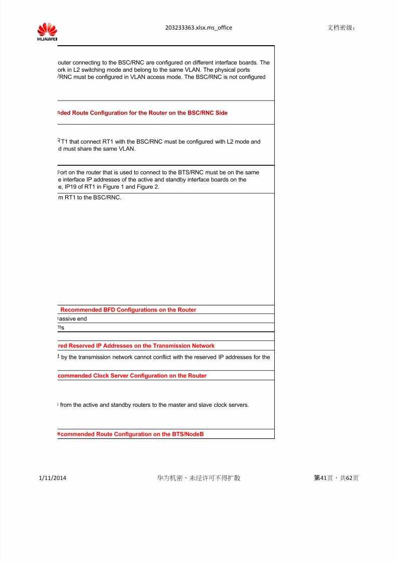
ded Route Configuration for the Router on the BSC/RNC Side
T1 that connect RT1 with the BSC/RNC must be configured with L2 mode and
d must share the same VLAN.
ort on the router that is used to connect to the BTS/RNC must be on the same
e interface IP addresses of the active and standby interface boards on the
e, IP19 of RT1 in Figure 1 and Figure 2.
commended Clock Server Configuration on the Router
outer connecting to the BSC/RNC are configured on different interface boards. The
ork in L2 switching mode and belong to the same VLAN. The physical ports
RNC must be configured in VLAN access mode. The BSC/RNC is not configured
Recommended BFD Configurations on the Router
1/11/2014 华为机密,未经许可不得扩散 第41页,共62页
8/13/2019 Configuration Check
http://slidepdf.com/reader/full/configuration-check 42/62
203233363.xlsx.ms_office 文档密级:
ion 5:
om the BTS, NodeB, gateway, and router to NodeB IP1.
m the BTS, NodeB, gateway, and router to BTS IP2.
ion 6:
om the BTS, NodeB, gateway, and router to NodeB IP1 and NodeB IP2.
m the BTS, NodeB, gateway, and router to BTS IP3.
ion 3:
om the BTS, NodeB, gateway, and router to NodeB IP1 and NodeB IP2.
m the BTS, NodeB, gateway, and router to NodeB IP3, NodeB IP4, and BTS IP5.
ion 4:
om the BTS, NodeB, gateway, and router to NodeB IP1, NodeB IP2, and NodeB
m the BTS, NodeB, gateway, and router to NodeB IP4, NodeB IP5, and BTS IP6.
ion 1:
om the BTS, NodeB, gateway, and router to NodeB IP1.
m the BTS, NodeB, gateway, and router to BTS IP3 and NodeB IP2.
ion 2:
om the BTS, NodeB, gateway, and router to NodeB IP1 and NodeB IP2.
m the BTS, NodeB, gateway, and router to NodeB IP3 and BTS IP4.
1/11/2014 华为机密,未经许可不得扩散 第42页,共62页

8/13/2019 Configuration Check
http://slidepdf.com/reader/full/configuration-check 43/62
203233363.xlsx.ms_office 文档密级:
red Reserved IP Addresses on the Transmission Network
1/T1 interface of the BTS/NodeB: All PPP/MP links can use the same device IP
rge network segment on the router side.
eren rom e n er ace a ress on e o e , con gure e os rou e
ts to the BTS/NodeB through the E1 interface) to the OM IP address of the
ist, you need to add the static routes to the BTS.
or ng, t e convers on s a owe etween t e o e an t e router.
he VLAN ID of the BTS/NodeB maps the VLAN ID of the router before and after the
f the E1/T1 Interface Connecting the BTS/NodeB with the Router
rts the function of assigning the interface IP address for the BTS/NodeB on the
/PPP interface.
ended VLAN Configurations on the Transmission Network
red for the BTS/NodeB, set the LSW that directly connects to the BTS/NodeB to
nd set the PVID to be consistent with the VLAN ID of the BTS/NodeB.
onfigured for the BTS/NodeB, set the LSW that directly connects to the BTS/NodeB
K mode, add VLAN IDs of the BTS/NodeB to the list of VLAN IDs allowed by the
to an idle VLAN ID.
tly connects to the router, no VLAN is configured for router interfaces.
ion 8:
om the BTS, NodeB, gateway, and router to NodeB IP1, NodeB IP2, NodeB IP3,
m the BTS, NodeB, gateway, and router to NodeB IP5 and BTS IP6.
configured with two routers (see Figure 1), configure VRRP (for example, VRRP 2
rfaces of the routers connecting to the BTS/NodeB.
rity of VRRP2 configured on RT1 is higher than that of VRRP2 configured on RT2
the primary router.
ion 7:
om the BTS, NodeB, gateway, and router to NodeB IP1, NodeB IP2, and NodeB
m the BTS, NodeB, gateway, and router to BTS IP4.
1/11/2014 华为机密,未经许可不得扩散 第43页,共62页
8/13/2019 Configuration Check
http://slidepdf.com/reader/full/configuration-check 44/62
203233363.xlsx.ms_office 文档密级:
rfaces and sub-interfaces on the router cannot conflict with the reserved IP
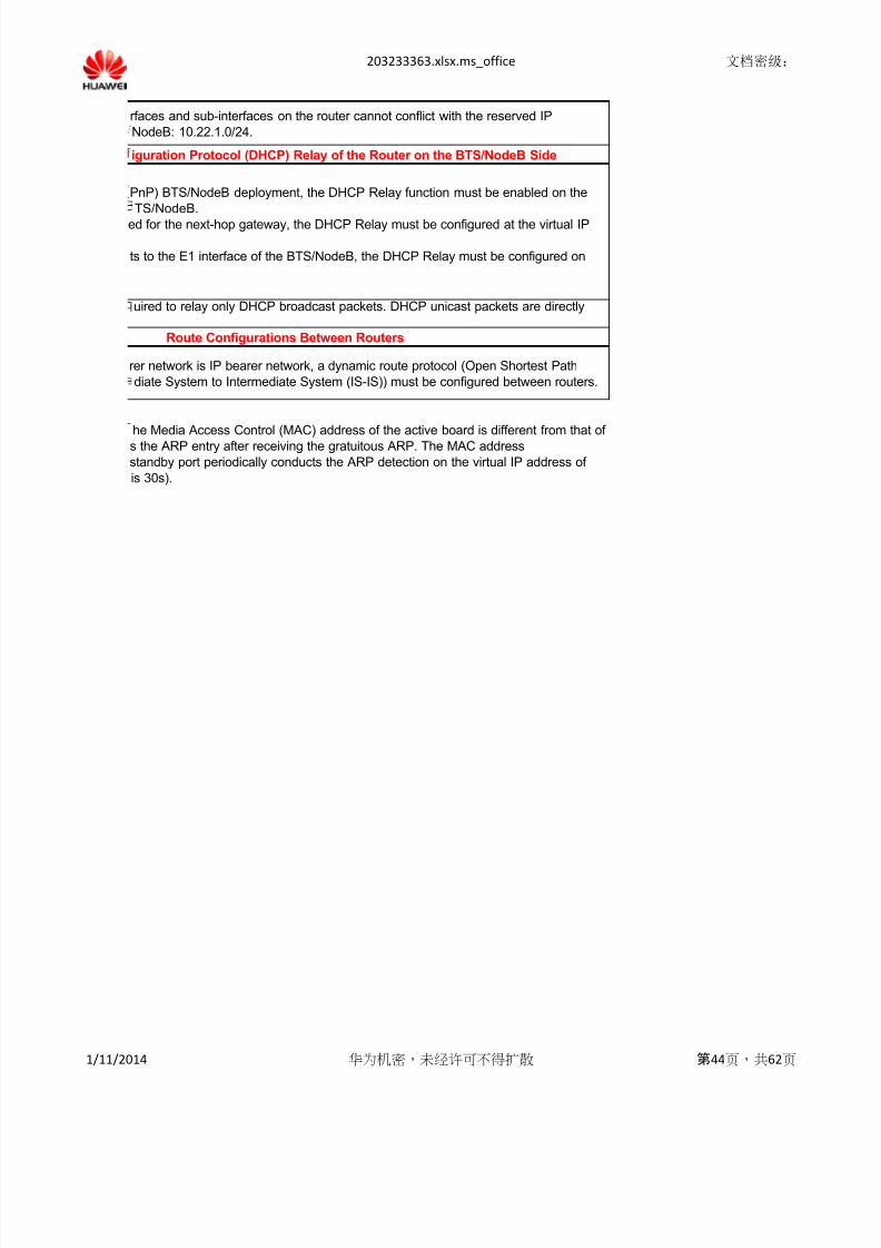
NodeB: 10.22.1.0/24.
he Media Access Control (MAC) address of the active board is different from that ofs the ARP entry after receiving the gratuitous ARP. The MAC address
standby port periodically conducts the ARP detection on the virtual IP address of
is 30s).
Route Configurations Between Routers
rer network is IP bearer network, a dynamic route protocol (Open Shortest Path
diate System to Intermediate System (IS-IS)) must be configured between routers.
iguration Protocol (DHCP) Relay of the Router on the BTS/NodeB Side
PnP) BTS/NodeB deployment, the DHCP Relay function must be enabled on the
TS/NodeB.
ed for the next-hop gateway, the DHCP Relay must be configured at the virtual IP
ts to the E1 interface of the BTS/NodeB, the DHCP Relay must be configured on
uired to relay only DHCP broadcast packets. DHCP unicast packets are directly
1/11/2014 华为机密,未经许可不得扩散 第44页,共62页

8/13/2019 Configuration Check
http://slidepdf.com/reader/full/configuration-check 45/62
203233363.xlsx.ms_office 文档密级:
E1 Delay inMultilink PPP
Mode (ms)
Maximum
Value
Expected
Value
Maximum
Value
Maximum
Value
Expected
Value
Iub interface
(common)40 10
101.00E-06 1.00E-07
Iub interface
(satellite
transmission)
350 300
10
1.00E-07 1.00E-08
MaximumValue
ExpectedValue
MaximumValue
ExpectedValue
MaximumValue
Iub interface
(common)40 10 15 2 1.00E-03
Iub interface
(satellite
transmission)
1.00E-03
Maximum
Value
Expected
Value
Maximum
Value
Expected
Value
Maximum
Value
Abis interface
(common) 40 15 15 8 1.00E-03 Abis interface
(satellite
transmission)
350 300 40 20
Notes:
Service Type PHB DSCP VLAN PriQueue on
BSC
Iub Signal CS6 48 6 0
CCH&SRB&AMR EF 46 5 0
Conversational&
streaming AF41 34 4 1
R99 interactive&
background AF21 18 2 3
Transmission QoS Requirements for the Iub/Abis Interface
In IP over E1 mode, the quality of service (QoS) requirements of the UMTS network for the
intermediate network are as follows:
One-Way Delay (ms) Bit Error Rate (BER)
1. The maximum values indicate the basic commercial requirements for deploying radio serv
QoS Requirements of the GSM and UMTS Networks for the Transport Network
In IP over Ethernet mode, the QoS requirements of the UMTS network for the intermediate
One-Way Delay (ms) Jitter (ms) Packet Loss Ra
Bidirectional 600 Bidirectional 50
n over erne mo e, e o requ remen s o e ne wor or e n erme a e
follows:One-Way Delay (ms) Jitter (ms) Packet Loss Ra
5.00E-04
2. The expected values indicate the requirements on the transport network when customers
3. These QoS requirements are inapplicable to satellite bearers.
Default Service Priority Mapping for the Iub Interface
1/11/2014 华为机密,未经许可不得扩散 第45页,共62页

8/13/2019 Configuration Check
http://slidepdf.com/reader/full/configuration-check 46/62
203233363.xlsx.ms_office 文档密级:
HSxPA
interactive&
background
AF11 10 1 4
NodeB OM High EF 46 5 0
NodeB OM Low AF21 18 2 3
IP clock EF 46 5 0
Network
Technology
GSM
UMTS
SRAN
Network TechnoPriority Configurations of the Intermediate Network
QoS Requirements of the Radio Network for Queue Configurations on the Transport
Network (Note1)
Recommended solution: You do not need to modify the default QoS mechanism on the radio network. The in
devices generally support the basic QoS mechanism: L3 supports eight priority queues (CS7/CS6/EF/AF4/A
The basic QoS mechanism meets the priority requirements of the radio bearer networks.
Priority Configurations of the Intermediate Network
ata w t t e erent ate serv ces co e po nts s o , , , , an or w t
ueues.Data with the DSCPs of 48, 46, 34, 18, and 10 or with the VLAN priorities of 6, 5, 4, 2, and 1
Data with the DSCPs of 48, 46, 34, 26, 18, and 10 or with the VLAN priorities of 6, 5, 4, 3, 2,
Alternative solution: You do not need to modify the default configurations on radio network devices. The map
configured on the intermediate network needs to be adjusted. The mapping between the DSCP/VLAN priority
SRAN
The four priority queues are mapped onto the DSCP (48+46)/34/26/(18+10) or VLAN priority
The three priority queues are mapped onto the DSCP (48+46)/(34+26)/(18+10) or VLAN pri
The two priority queues are mapped onto the DSCP (48+46+34+26)/(18+10) or VLAN priorit
Note 1: It is recommended that DSCPs be not combined on the radio network side.
Note 2: On the SRAN, the low-priority packet switched (PS) services on the GSM network are combined to hiaccess (HSPA) services on the UMTS network.
Principle: The queue combination indicates the combination of high-priority queues and the combination of lo
GSM
The four priority queues are mapped onto the DSCP (48+46)/34/26/18 or VLAN priority (6+5
The three priority queues are mapped onto the DSCP (48+46)/34/(26+18) or VLAN priority (
The two priority queues are mapped onto the DSCP (48+46)/(34+26+18) or VLAN priority (6
UMTS
The three priority queues are mapped onto the DSCP (48+46+34)/18/10 or VLAN priority (6
The two priority queues are mapped onto the DSCP (48+46+34)/(18+10) or VLAN priority (6
1/11/2014 华为机密,未经许可不得扩散 第46页,共62页

8/13/2019 Configuration Check
http://slidepdf.com/reader/full/configuration-check 47/62
203233363.xlsx.ms_office 文档密级:
E1 Delayin Multilink
PPP
Maximum
Value
Expected
Value
Maximum
Value
Maximum
Value
Expected
Value
Abis interface
(common)40 15
101.00E-06 1.00E-07
Abis interface
(satellite
transmission)
350 300
10
1.00E-07 1.00E-08
ExpectedValue
1.00E-04
1.00E-04
Expected
Value
5.00E-04
Service Type PHB DSCP VLAN PriQueue on
BSC
ESL/ OML/RSL CS6 48 6 0
CS Voice EF 46 5 0
CS Data/ PS
High PRI
AF41 34 4 1
PS low PRI AF31 26 3 2
In IP over E1 mode, the QoS requirements of the GSM network for the
intermediate network are as follows:
One-Way Delay (ms) BER
ices.
etwork are as
tio
ne wor are as
tio
have high KPI
Default Service Priority Mapping for the Abis interface
1/11/2014 华为机密,未经许可不得扩散 第47页,共62页

8/13/2019 Configuration Check
http://slidepdf.com/reader/full/configuration-check 48/62
203233363.xlsx.ms_office 文档密级:
EML AF21 18 2 3
IP Clock EF 46 5 0
ermediate network adopts the basic eight-queue mechanism. Network
3/AF2/AF1/BE) and L2 supports eight priority queues of the VLAN.
t e pr or t es o , , , , an s str ute nto ve pr or ty
is distributed into five priority queues.
and 1 is distributed into six priority queues.
ping between the DSCP/VLAN priority and the priority queues
and the priority queues needs to be configured on customer devices.
.
(6+5)/4/3/(2+1).
rity (6+5)/(4+3)/(2+1).
y (6+5+4+3)/(2+1) (Note2).
gh-priority queues, avoiding being impacted by high speed packet
w-priority queues. Therefore, at least two queues must be available.
)/4/3/2.
+5)/4/(3+2).
+5)/(4+3+2)..
5+4)/2/1.
+5+4)/(2+1).
1/11/2014 华为机密,未经许可不得扩散 第48页,共62页
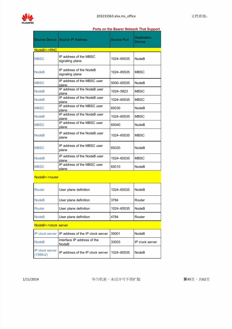
8/13/2019 Configuration Check
http://slidepdf.com/reader/full/configuration-check 49/62
203233363.xlsx.ms_office 文档密级:
Source Device Source IP Address Source PortDestination
Device
NodeB<->RNC
MBSC IP address of the MBSCsignaling plane
1024–65535 NodeB
NodeBIP address of the NodeB
signaling plane 1024–65535 MBSC
MBSCIP address of the MBSC user
plane 5000–65535 NodeB
NodeBIP address of the NodeB user
plane 1024–5823 MBSC
NodeBIP address of the NodeB user
plane 1024–65535 MBSC
MBSCIP address of the MBSC user
plane65030 NodeB
NodeB IP address of the NodeB userplane
1024–65535 MBSC
MBSCIP address of the MBSC user
plane65040 NodeB
NodeBIP address of the NodeB user
plane 1024–65535 MBSC
MBSCIP address of the MBSC user
plane65020 NodeB
NodeBIP address of the NodeB user
plane 1024–65535 MBSC
MBSCIP address of the MBSC user
plane65010 NodeB
NodeB<->router
Router User plane definition 1024–65535 NodeB
NodeB User plane definition 3784 Router
Router User plane definition 1024–65535 NodeB
NodeB User plane definition 4784 Router
NodeB<->clock server
IP clock server IP address of the IP clock server 35001 NodeB
NodeBInterface IP address of the
NodeB33003 IP clock server
IP clock server
(1588v2)IP address of the IP clock server 1024–65535 NodeB
Ports on the Bearer Network That Support
1/11/2014 华为机密,未经许可不得扩散 第49页,共62页
8/13/2019 Configuration Check
http://slidepdf.com/reader/full/configuration-check 50/62
203233363.xlsx.ms_office 文档密级:
NodeBInterface IP address of the
NodeB319
IP clock server
(1588v2)
IP clock server
(1588v2)IP address of the IP clock server 1024–65535 NodeB
NodeB Interface IP address of theNodeB
320 IP clock server(1588v2)
NodeB<->security gateway
NodeBInterface IP address of the
NodeB500 Security gateway
Security
gateway
IP address of the security
gateway500 NodeB
NodeB<->PKI
server
NodeB
OM IP address of the
NodeB/interface IP address of
the NodeB
1024–65535
Certificate
Authority (CA)
server
NodeB<->M2000 server/LMT
M2000 server
LMTIP address of the M2000 server 1024–65535 NodeB
M2000 server
LMTIP address of the M2000 server 1024–65535 NodeB
M2000 server
LMTIP address of the M2000 server 1024–65535 NodeB
M2000 server
LMTIP address of the M2000 server 1024–65535 NodeB
M2000 server IP address of the M2000 server 1024–65535 NodeB
NodeB<->Dynamic Host Configuration Protocol (DHCP) server
DHCP server IP address of the DHCP server 67 NodeB
DHCP client 0.0.0.0 68 DHCP server
1/11/2014 华为机密,未经许可不得扩散 第50页,共62页
8/13/2019 Configuration Check
http://slidepdf.com/reader/full/configuration-check 51/62
203233363.xlsx.ms_office 文档密级:
NodeB<->FTP
server
FTP server IP address of the FTP server 21 NodeB
NodeB OM IP address of the NodeB 1024–65535 FTP server
NodeB<->Network Time Protocol (NTP) server
NTP server IP address of the NTP server 123 NodeB
1/11/2014 华为机密,未经许可不得扩散 第51页,共62页

8/13/2019 Configuration Check
http://slidepdf.com/reader/full/configuration-check 52/62
203233363.xlsx.ms_office 文档密级:
Destination IP Address
Destination
Port
(Listening)
Protocol Port Description
IP address of the NodeBsignaling plane
1024–65535
SCTP SCTP connection
IP address of the MBSC
signaling plane
1024–6553
5SCTP SCTP connection
IP address of the NodeB
user plane 1024–5823 UDP Transmitting service data
IP address of the MBSC
user plane
5000–6553
5UDP Transmitting service data
IP address of the MBSC
user plane65030 UDP UDP Ping
IP address of the NodeB
user plane
1024–6553
5UDP UDP Ping
IP address of the MBSCuser plane
65040 UDP Transmission quality detection
IP address of the NodeB
user plane
1024–6553
5UDP Transmission quality detection
IP address of the MBSC
user plane65020 UDP IPPM
IP address of the NodeB
user plane
1024–6553
5UDP IPPM
IP address of the MBSC
user plane65010 UDP Sending FPMUX packets
IP address of the NodeB
user plane
1024–6553
5UDP Sending FPMUX packets
User plane definition 3784 UDPSending single-hop BFD
packets
User plane definition 1024–6553
5UDP
Sending single-hop BFD
packets
User plane definition 4784 UDPSending multi-hop BFD
packets
User plane definition 1024–6553
5UDP
Sending multi-hop BFD
packets
Interface IP address of the
NodeB33003 UDP Clock server of Huawei
IP address of the IP clock
server 35001 UDP Clock server of Huawei
Interface IP address of the
NodeB319 UDP
Sending 1588V2 over UDP
common messages
the Required Services on the Iub Interface
1/11/2014 华为机密,未经许可不得扩散 第52页,共62页
8/13/2019 Configuration Check
http://slidepdf.com/reader/full/configuration-check 53/62
203233363.xlsx.ms_office 文档密级:
IP address of the IP clock
server
1024–6553
5UDP
Sending 1588V2 over UDP
common messages
Interface IP address of the
NodeB320 UDP
Sending 1588V2 over UDP
event messages
IP address of the IP clockserver
1024–6553
5UDP Sending 1588V2 over UDP
event messages
IP address of the security
gateway500 UDP
IP Security (IPSec) Internet
Key Exchange (IKE)
Interface IP address of the
NodeB500 UDP IPSec IKE
IP address of the CA server 80/8080/44
3TCP
Connecting the CA server;
applying for and updating the
certificate
OM IP address of the
NodeB
Local IP address of the
NodeB
6000 TCP Sending MML commands
OM IP address of the
NodeB
Local IP address of the
NodeB
6001 TCP Sending alarms
OM IP address of the
NodeB
Local IP address of the
NodeB
6006 TCPUsed by the OM channel;
supporting the binary format
OM IP address of the
NodeB
Local IP address of the
NodeB
6007 TCP
A common port for sending
test messages, alarm
messages, and MML
commands
OM IP address of the
NodeB45300 UDP OM channel switch
OM IP address of the
NodeB68 UDP
DHCP client (when the M2000
serves as the DHCP server)
OM IP address of the
NodeB67 UDP DHCP relay
1/11/2014 华为机密,未经许可不得扩散 第53页,共62页

8/13/2019 Configuration Check
http://slidepdf.com/reader/full/configuration-check 54/62
203233363.xlsx.ms_office 文档密级:
OM IP address of the
NodeB
1024–6553
5TCP FTP control
IP address of the FTP
server21 TCP FTP control
OM IP address of the
NodeB 123 UDP
NTP client (when the M2000
serves as the NTP server)
1/11/2014 华为机密,未经许可不得扩散 第54页,共62页
8/13/2019 Configuration Check
http://slidepdf.com/reader/full/configuration-check 55/62
203233363.xlsx.ms_office 文档密级:
Source Device Source IP AddressSource
Port
Destination
Device
BTS<->BSC
BTS
OM IP address of the BTS/IP
address of the BTS signaling
plane
12288–28673
BSC
BSC
OM IP address of the BSC/IP
address of the BSC signaling
plane
4502–464
9BTS
BTSIP address of the BTS user
plane
4096–122
87BSC
BSCIP address of the BSC user
plane
5000–650
00BTS
BTSIP address of the BTS user
plane
1024–655
35BSC
BSCIP address of the BSC user
plane
1024–655
35BTS
BTS IP address of the BTS userplane
1024–655
35BSC
BSCIP address of the BSC user
plane
1024–655
35BTS
BSCIP address of the BSC user
plane
65040
1024–358
4
BTS
BTSIP address of the BTS user
plane
65040
1024–358
4
BSC
BSCIP address of the BSC user
plane65042 BTS
BTSIP address of the BTS user
plane65042 BSC
BTS OM IP address of the BTS 65043 BSC
BSC OM IP address of the BSC 65042 BTS
BTS<->router
BTSInterface IP address of the
BTS
49152–65
535Router
Router IP address of the router 49152–65
535BTS
BTSInterface IP address of the
BTS
49152–65
535
Router
Router IP address of the router 49152–65
535BTS
BTS<->clock server
BTSOM IP address of the BTS/IP
address of the BTS user plane319
IP clock server
(1588v2)
Ports on the Bearer Network That Suppo
1/11/2014 华为机密,未经许可不得扩散 第55页,共62页

8/13/2019 Configuration Check
http://slidepdf.com/reader/full/configuration-check 56/62
203233363.xlsx.ms_office 文档密级:
IP clock server
(1588v2)
IP address of the IP clock
server 319 BTS
BTSOM IP address of the BTS/IP
address of the BTS user plane320
IP clock server
(1588v2)
IP clock server(1588v2)
IP address of the IP clockserver
320 BTS
PC<->BTS
PC IP address of the PC 1024–655
35BTS
BTSIP address of the BTS console
port700 PC
BTS<->security
gateway
BTSInterface IP address of the
BTS500 Security gateway
Security
gateway
IP address of the security
gateway500 BTS
BTS<->PKI server
BTS
OM IP address of the
BTS/interface IP address of
the BTS
1024–655
35CA server
CA server IP address of the CA server 80/8080/4
43BTS
BTS
OM IP address of the
BTS/interface IP address of
the BTS
1024–655
35
Lightweight
Directory Access
Protocol (LDAP)
Server
LDAP Server CR/CRL IP address 0–65535 BTS
BTS<->File Transfer Protocol (FTP) server
BTS OM IP address of the BTS 1024–655
35FTP server
FTP server IP address of the FTP server 21–65535 BTS
1/11/2014 华为机密,未经许可不得扩散 第56页,共62页

8/13/2019 Configuration Check
http://slidepdf.com/reader/full/configuration-check 57/62
203233363.xlsx.ms_office 文档密级:
BTS OM IP address of the BTS 49152–65
535FTP server
FTP server IP address of the FTP server
Determine
d by the
server
BTS
BTS<->DHCP server
BTS
OM IP address of the
BTS/interface IP address of
the BTS
67 DHCP server
DHCP server IP address of the DHCP server 67 BTS
BTS 0.0.0.0 67
DHCP
server/DHCP
Relay
DHCP
server /DHCP
relay server
Broadcast address/IP address
of the DHCP relay server 68 BTS
BTS<->a device where the ping detection and TraceRt detection are enabled
BSC
Interface IP address of the
BSC/loopback IP address
(source IP address of the ping
detection)
BTS
BTS
Interface IP address of the
BTS/loopback IP address(destination IP address of the
ping detection)
BSC
BSC
Interface IP address of the
BSC/loopback IP address
(source IP address of the
TraceRt detection)
1024–655
35BTS
BTS
Interface IP address of the
BTS/loopback IP address
(destination IP address of the
TraceRt detection)
65300–65
535BSC
1/11/2014 华为机密,未经许可不得扩散 第57页,共62页

8/13/2019 Configuration Check
http://slidepdf.com/reader/full/configuration-check 58/62
203233363.xlsx.ms_office 文档密级:
Destination IP Address
Destinatio
n Port
(Listening)
Protocol Port Description
OM IP address of the BSC/IP
address of the BSC signaling
plane
4502–4649
UDP Transmitting OM andsignaling data
OM IP address of the BTS/IP
address of the BTS signaling
plane
12288–28
673UDP
Transmitting OM and
signaling data
IP address of the BSC user
plane
5000–650
00UDP Transmitting service data
IP address of the BTS user
plane
4096–122
87UDP Transmitting service data
IP address of the BSC user
plane65020 UDP Sending IP PM packets
IP address of the BTS user
plane65020 UDP Sending IP PM packets
IP address of the BSC userplane
65010 UDP Sending Abis MUX packets
IP address of the BTS user
plane65010 UDP Sending Abis MUX packets
IP address of the BTS user
plane
65040
1024–358
4
UDP Network quality detection
IP address of the BSC user
plane
65040
1024–358
4
UDP Network quality detection
IP address of the BTS user
plane65042 UDP UDP Ping
IP address of the BSC user
plane65042 UDP UDP Ping
OM IP address of the BSC 65042 UDP
Checking whether the
transmission channel
functions properly.
OM IP address of the BTS 65043 UDP
Checking whether the
transmission channel
functions properly.
IP address of the router 3784 UDPSending single-hop BFD
packets
Interface IP address of the
BTS3784 UDP
Sending single-hop BFD
packets
IP address of the router 4784 UDPSending multi-hop BFD
packetsInterface IP address of the
BTS4784 UDP
Sending multi-hop BFD
packets
IP address of the IP clock
server 319 UDP
Sending 1588V2 over UDP
event messages
rt the Required Services on the Abis Interface
1/11/2014 华为机密,未经许可不得扩散 第58页,共62页

8/13/2019 Configuration Check
http://slidepdf.com/reader/full/configuration-check 59/62
203233363.xlsx.ms_office 文档密级:
OM IP address of the BTS/IP
address of the BTS user plane319 UDP
Sending 1588V2 over UDP
event messages
IP address of the IP clock
server 320 UDP
Sending 1588V2 over UDP
common messages
OM IP address of the BTS/IPaddress of the BTS user plane
320 UDP Sending 1588V2 over UDPcommon messages
IP address of the BTS console
port700 TCP Sending SMT packets
PC IP 1024–655
35
IP address of the security
gateway500 UDP IKE negotiation
Interface IP address of the
BTS500 UDP IKE negotiation
IP address of the CA server 80/8080/4
43TCP Digital certificate CMPV2
OM IP address of the
BTS/interface IP address of
the BTS
1024–655
35TCP Digital certificate CMPV2
CR/CRL IP address 0–65535 TCP LDAP
OM IP address of the
BTS/interface IP address of
the BTS
1024–655
35TCP LDAP
IP address of the FTP server 21–65535 TCP
FTP control.
The FTP control port is port
21 by default, which can be
changed.
OM IP address of the BTS 1024–655
35TCP
FTP control.The FTP control port is port
21 by default, which can be
changed.
1/11/2014 华为机密,未经许可不得扩散 第59页,共62页
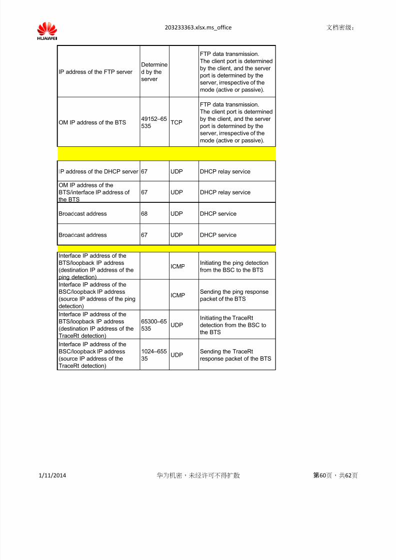
8/13/2019 Configuration Check
http://slidepdf.com/reader/full/configuration-check 60/62
203233363.xlsx.ms_office 文档密级:
IP address of the FTP server
Determine
d by the
server
FTP data transmission.
The client port is determined
by the client, and the server
port is determined by the
server, irrespective of the
mode (active or passive).
OM IP address of the BTS 49152–65
535TCP
FTP data transmission.
The client port is determined
by the client, and the server
port is determined by the
server, irrespective of the
mode (active or passive).
IP address of the DHCP server 67 UDP DHCP relay service
OM IP address of the
BTS/interface IP address ofthe BTS
67 UDP DHCP relay service
Broadcast address 68 UDP DHCP service
Broadcast address 67 UDP DHCP service
Interface IP address of the
BTS/loopback IP address
(destination IP address of the
ping detection)
ICMPInitiating the ping detection
from the BSC to the BTS
Interface IP address of the
BSC/loopback IP address(source IP address of the ping
detection)
ICMP Sending the ping responsepacket of the BTS
Interface IP address of the
BTS/loopback IP address
(destination IP address of the
TraceRt detection)
65300–65
535UDP
Initiating the TraceRt
detection from the BSC to
the BTS
Interface IP address of the
BSC/loopback IP address
(source IP address of the
TraceRt detection)
1024–655
35UDP
Sending the TraceRt
response packet of the BTS
1/11/2014 华为机密,未经许可不得扩散 第60页,共62页
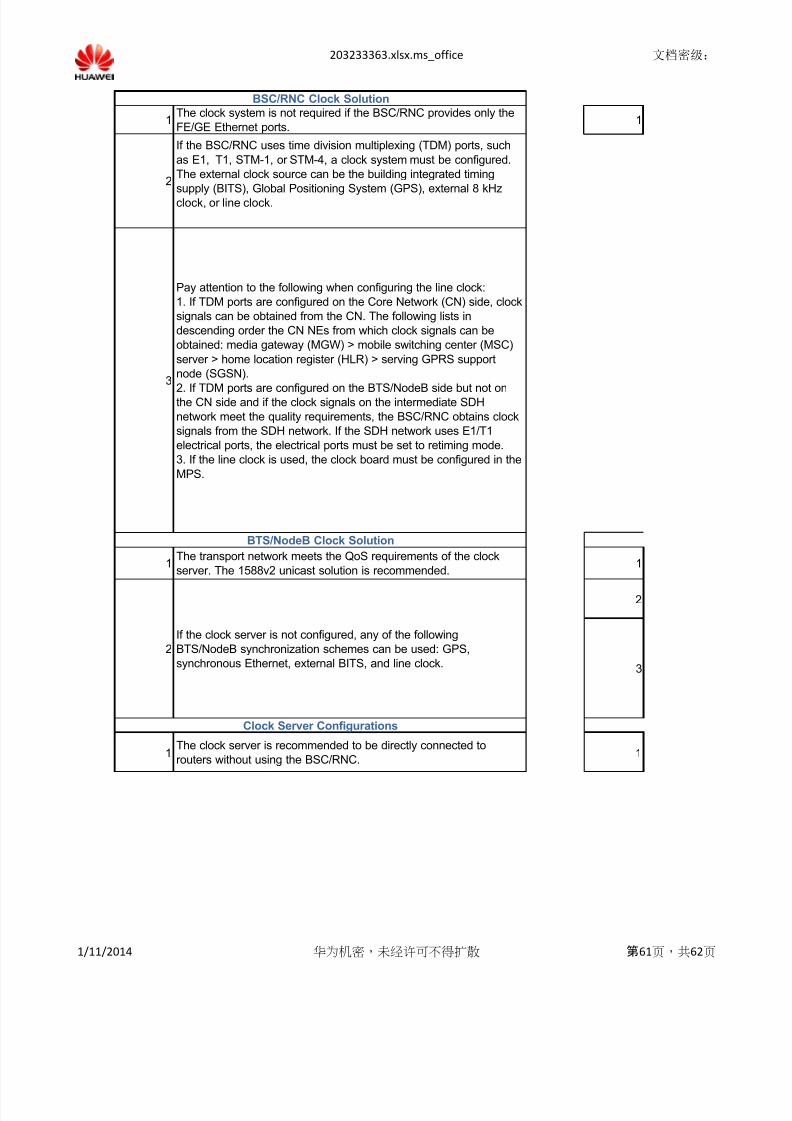
8/13/2019 Configuration Check
http://slidepdf.com/reader/full/configuration-check 61/62
203233363.xlsx.ms_office 文档密级:
2
1 1
BSC/RNC Clock Solution
BTS/NodeB Clock Solution
Clock Server Configurations
3
2
1
1
2
1The clock system is not required if the BSC/RNC provides only the
FE/GE Ethernet ports.
Pay attention to the following when configuring the line clock:
1. If TDM ports are configured on the Core Network (CN) side, clock
signals can be obtained from the CN. The following lists in
descending order the CN NEs from which clock signals can be
obtained: media gateway (MGW) > mobile switching center (MSC)
server > home location register (HLR) > serving GPRS support
node (SGSN).
2. If TDM ports are configured on the BTS/NodeB side but not onthe CN side and if the clock signals on the intermediate SDH
network meet the quality requirements, the BSC/RNC obtains clock
signals from the SDH network. If the SDH network uses E1/T1
electrical ports, the electrical ports must be set to retiming mode.
3. If the line clock is used, the clock board must be configured in the
MPS.
If the BSC/RNC uses time division multiplexing (TDM) ports, such
as E1, T1, STM-1, or STM-4, a clock system must be configured.
The external clock source can be the building integrated timing
supply (BITS), Global Positioning System (GPS), external 8 kHzclock, or line clock.
The clock server is recommended to be directly connected to
routers without using the BSC/RNC.
The transport network meets the QoS requirements of the clock
server. The 1588v2 unicast solution is recommended.1
If the clock server is not configured, any of the following
BTS/NodeB synchronization schemes can be used: GPS,
synchronous Ethernet, external BITS, and line clock. 3
1/11/2014 华为机密,未经许可不得扩散 第61页,共62页
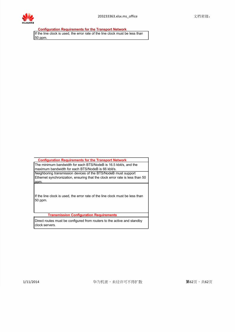
8/13/2019 Configuration Check
http://slidepdf.com/reader/full/configuration-check 62/62
203233363.xlsx.ms_office 文档密级:
Configuration Requirements for the Transport Network
Configuration Requirements for the Transport Network
Transmission Configuration Requirements
If the line clock is used, the error rate of the line clock must be less than
50 ppm.
Direct routes must be configured from routers to the active and standby
clock servers.
The minimum bandwidth for each BTS/NodeB is 16.5 kbit/s, and the
maximum bandwidth for each BTS/NodeB is 66 kbit/s.
If the line clock is used, the error rate of the line clock must be less than
50 ppm.
Neighboring transmission devices of the BTS/NodeB must supportEthernet synchronization, ensuring that the clock error rate is less than 50
ppm.


