
O W N E R S M A N U A L
C o n n e c t i o n G u i d e

c
contents
cd players2 cds4 cdx6 cd5
tuners8 nat 019 nat 029 nat 05
headphones10 headline
phono stage11 stageline
preamplifiers12 nac 5214 nac 8218 nac 10220 nac 112
a/v processor22 av2
integrated amplifier24 nait 5
power amplifiers28 nap 50029 nap 13530 nap 250, nap 180, nap 15031 nap 140, nap 6-50, nap v175
power supplies32 supercap, hi-cap33 flatcap 2
active crossovers40 snaxo 3-6, snaxo 2-4, ixo 2
introductionThis connection guide collects together illustrationsof product connection panels and many of the mostoften used system connection diagrams. Eachillustration and diagram can also be found in theappropriate product Owners Manual. This guideshould not be seen as a replacement for specificOwners Manuals as these contain important safetyand installation information.

cable
direction
marker
3
cd players
cds connection to xps power supply
cdsxps
cd p
laye
rs
cds
2
tracktimerepeatprogram
to preamplifier mains input
to preamplifier
5-5 180˚ DIN
11-11 Burndy
Interconnects
displayprevious
next
pausestop
play
ch1ncnc
-vech2
cds output
5
cd players
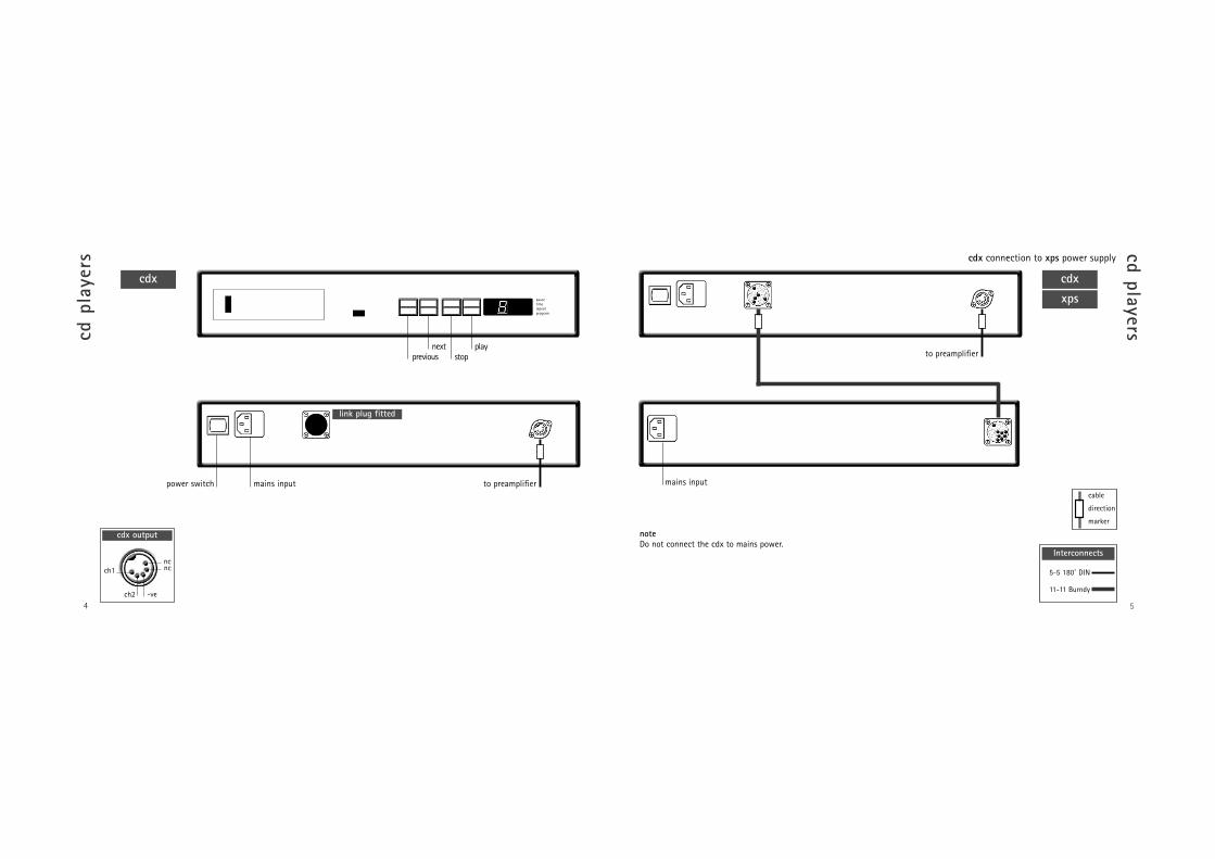
cdx connection to xps power supply
cdx xps
cd p
laye
rs
cdx
4
pausetimerepeatprogram
link plug fitted
to preamplifiermains inputpower switch
to preamplifier
cable
direction
marker
5-5 180˚ DIN
11-11 Burndy
Interconnects
mains input
noteDo not connect the cdx to mains power.
ch1ncnc
-vech2
cdx output
previousnext
stopplay

7
cd players
cd5 connection to flatcap 2 power supply
cd p
laye
rs
6
link plug fitted
to preamplifierrc5 input
link plug removed
to preamplifier
ch1ncnc
-ve
ch2
cd5 output
cable
direction
marker
5-5 180˚ DIN
5-5 240˚ DIN
Interconnects
cd5 flatcap 2
cd5
previousnext
stopplay
notecd5 players manufactured after April 2001 are fittedwith an RC5 control input. This input is designed toaccept external control signals for multi-roomapplications. Contact your dealer for furtherinformation on its use.
mains inputpower switch
mains inputpower switch
mains inputpower switch

9
tunerstune
rs
napstnat 01
8
ch1ncnc
-vech2
nat 01 output
nat 01 connection to napst power supply
to preamplifier 75 ohm FM aerial mains input
rc5 input
cable
direction
marker
5-5 180˚ DIN
5-5 240˚ DIN
Interconnects
ch1 ncnc
-ve
ch2
nat 02/05 output
75 ohm FM aerialto preamplifier
75 ohm FM aerial to preamplifier
nat 05 nat 02
noteThe RC5 input is designed to acceptexternal control signals for multi-roomapplications. Contact your dealer forfurther information on its use.
mains inputpower switch
power switch
mains input

to:nac 52, nac 82, nac 102:socket 4, 5 or 6.nac 112, nait 5:socket 3, 4 or 5.
11
phono stage
stageline connection to nait 5 or nac 112
stageline connection to flatcap 2
stageline
head
phon
e am
plif
ier headline connection to napsc or hi-cap power supply.
headline
10
from napsc
to:nac 52, nac 82, nac 102:socket 4, 5 or 6.nac 112, nait 5:socket 3, 4 or 5.
all link plugs fitted cover fitted
5-2 SLIC
Captive 5/180̊ DIN
Interconnects
cable
direction
marker
hi-cap
to preamp. 4to 5 pininterconnectrequiredmains input
mains inputpower switch
mains inputpower switch
5-5 240˚DIN
4-5 DIN
Interconnects

13
preamplifiers
nac 52 connection to supercap power supply
nac 52 supercap
prea
mpl
ifie
rs
nac 52
12
6 5 4 3 2a 2b (blank fitted)
1
high level inputs phono input
digitalpower supply
audio power supplych1ncnc
-vech2
inputs 3 & 2a
ch1ch1ch2
-vech2
inputs 6, 5 & 4
input 2b
+vech1
ch2
-ve+ve
cable
direction
marker
5-5 240˚ DIN
16 -16 Burndy
Interconnects
1inputs
monovolume balancemute 2a/b
34
56rec
source
to nap 140, 150 or 180 power amplifiers (4 pin DIN) or nap 250 power amplifier (4 DIN-XLR)
to nap 135 or nap 500 power amplifiers (4 pin to XLR)mains input

15
preamplifiers
nac 82 connection to nap 140, 150 and nap 180 power amplifiers
nac 82 connected to one hi-cap or flatcap 2
nac 82 hi-cap
prea
mpl
ifie
rs
nac 82
14
6 5 4 3 2
1
high level inputs
outputs
phono input
napsc
link plugs fitted
napscto nap 140,150& 180 power
amplifiers
link plug fitted
napscch1ncnc
-vech2
inputs 3 & 2
ch1ch1ch2
-vech2
inputs 6, 5 & 4
noteThe napsc power supply mustbe connected to the nac 82 atall times.
4-4 DIN to nap 140, 150 & 180 4 DIN-XLR to nap 250
4 DIN-XLR tonap 135 & 500
cable
direction
marker
4-4 DIN
5-5 240˚ DIN
Interconnects
1inputs
monovolume balancemute 2
34
56rec
source
mains input

17
preamplifiers
nac 82 connection to supercap
nac 82 supercap
prea
mpl
ifie
rs nac 82 connection to two hi-caps or flatcaps
nac 82hi-cap
16
napsc
4-4 DIN to nap 140, 150 & 180 4 DIN-XLR to nap 250
4 DIN-XLR tonap 135 & 500
all link plugs removed
napsc
all link plugs removed
4-4 DIN to nap 140, 150 & 180 4 DIN-XLR to nap 250
4 DIN-XLR to nap 135 & 500
cable
direction
marker
5-5 240˚ DIN
Interconnects
cable
direction
marker
5-5 240˚ DIN
Interconnects
noteSound quality will be severely impaired if powersupplies are mixed. A flatcap together with a hi-capfor example. Similarly, both outputs of a Flatcap 2should not be used simultanesously to power onepreamp.
mains input mains input mains input
do not use
do not use

19
preamplifiers
nac 102 connection to hi-cap or flatcap
nac 102 hi-cap
prea
mpl
ifie
rs
nac 102 connection to one power amplifier with internal power supply
nac 102
18
1b high level inputsoutputs phono input
6 5 4 3 2 1a
4-4 DIN to nap 140, 150 & 180
noteWhen connecting a hi-cap without an napsc, thelarge link plug must be fitted (see previous page).
link plugs fitted
volume balance
inputs 3, 2 & 1a
inputs 6, 5 & 4
ch1 ncnc
-ve
ch2
ch1 ch1ch2
-ve
ch2
napsc(optional)
link plugs removed
4-4 DIN to nap 140, 150 & 180 4 DIN-XLR to nap 250
4 DIN-XLR tonap 135 & 500
cable
direction
marker
5-5 240˚ DIN
Interconnects
1inputs
monitormute 2
34
56
mains input

21
preamplifiers
nac 112 connection to flatcap 2
nac 112
prea
mpl
ifie
rs
nac 112
20
link plug & cover fitted
cover fitted
monitormute
cdtuner
tape a/vaux 1
aux 2volume
4-4 DIN to nap 140, 150 & 180 aux 1tape
a/v tuneraux 2cd
noteThe aux 2 input is provided with two sockets. Theleft hand socket, fitted on delivery with a blankingcover, is intended for use with a Stageline or Prefixphono stage and incorporates an appropriate DCpower supply.
ch1 ch1ch2
-ve
ch2
tape, a/v & aux 1inputs
ch1 ncnc
-ve
ch2
cd, tuner & aux 2inputs
nac 112 connection to one power amplifier with internal power supply
to nap 140, 150,180 & 250 power
amplifiers
to nap 135 & 500power amplifiers
for cd5, headline orstageline. Additionalinterconnectsrequired.
cable
direction
marker
5-5 240˚ DIN
Interconnects
flatcap 2
mains inputpower switch

digout
2
23
a/v processor
av2 connection to nap v175
av2 nap v175
a/v
proc
esso
r
av2
22
V 1 M U L
encoder input mode
mainsinput
rearout
cenout
surout
fr’tout
subout
rc5in
digout
1
digin1
datai/o
vs1
i/o
recout
recout
ch1left
an’gin 3
digin2
digoptout
digoptin 2
digoptin 1
an’gin 6
an’gin 4
ch 2right
an’gin 2(vip)
an’gin 1(vip)
powerswitch
ch1nc
ch2-ve
rear, surround &front outputs
centre output
cennc
(sub)-ve
analogue in 3
ch1 ch1
frontout
ch2
-ve
ch2
analogue in 2
ch1 ncnc
-ve
ch2
analogue in 1
ch1 ncnc
-ve
ch2
analogue in V2 & V1 multi mode
V2 V1
cenin ch1
ch2
-ve
subin
ch1 ch1ch2
-ve
ch2
rearin
surrin
frontin
mainsinput
powerswitch
- ++ - - +
4-4 DIN
Interconnects
to nap 140, 150, 180 &250 power amplifiers
to nap 140, 150, 180 &250 power amplifiers
to preamp

25
integrated amplifier
nait 5 connection to flatcap 2
nait 5
inte
grat
ed a
mpl
ifie
r
nait 5
24
link plugs/covers fitted
aux 1tapea/v
tuneraux 2out A
out Bincd
monitormute
cdtuner
tape a/vaux 1
aux 2volume
mains inputpower switch
ch1 ch1ch2
-ve
ch2
tape, a/v & aux 1inputs
ch1 ncnc
-ve
ch2
cd, tuner & aux 2inputs
+V in +V in
ch1
-ve
ch2
signal out A
for cd5, headline orstageline. Additionalinterconnectsrequired.
flatcap 2
mains inputpower switch
link plugs removed, cover fitted
mains inputpower switch
cable
direction
marker
4-4 DIN
5-5 240˚ DIN
Interconnects
speakersch1, left
speakersch2, right
- ++ -
- ++ -

27
integrated amplifier
nait 5 connection to flatcap 2 and nap150
nait 5
inte
grat
ed a
mpl
ifie
r nait 5 connection to nap 150
nap 150nait 5
26
link plug fitted
mains inputpower switch
mains inputpower switch
noteDo not connect the nait 5 to mains power.
cable
direction
marker
4-4 DIN
Interconnects
mains inputpower switch
link plugs removed flatcap 2 nap 150
cable
direction
marker
4-4 DIN
5-5 240˚ DIN
Interconnects
speakersch1, left
speakersch2, right
- ++ -
speakersch1, left
speakersch2, right
- ++ -
noteDo not connect the nait 5 to mains power.

29
power am
plifiers
nap 500 connection to na ps500 power supply
nap 135
pow
er a
mpl
ifie
rs
na ps500nap 500
28
2 1
-venc
ch2
Socket 2
-vech1
nc
Socket 1
-venc
ch2
Socket 2
-vech1
nc
Socket 1
speakersch1, left
speakersch2, right
mains input
to preamppower supply.
ch 1, left
to preamppower supply.ch 2, right
9-9 Burndy
Interconnects
mains input to power supply fan
2 1
fan
2 1
mains input to power supply
speakersch1, left
speakersch2, right
- +
- +
- ++ -

31
power am
plifierspow
er a
mpl
ifie
rs
nap 180nap 150
nap 250
30
-vech2
ch1
+ve
mains input to power supply
mains input to preamplifieror power supply
to preamplifieror power supply
speakersch1, left
speakersch2, right
-vech1
ch2
nap 250
nap 180
nap 140
mainsinput
powerswitch
to preamplifieror power supply
nap 140 nap 6-50 -ve
ch2+vech1
mainsinput
zone 1speakersch 1, left
zone 2speakersch 1, left
zone 1speakers
ch 2, right
zone 2speakers
ch 2, right
zone 3speakers
ch 2, right
zone 3speakersch 1, left
- + - + - +- + - + - +
mains input
zone 1trigger
zone 3zone 2
speakersch1, left
speakersch2, right
speakersch1, left
speakersch2, right
- ++ -
- ++ -- ++ -
speakersch1, left
speakersch2, right
- ++ -
mainsinput
powerswitch
to avprocessor
speakersch1, left
speakerscentre
- ++ -
napv 175
nap 150
ch1+ve
ch2-ve
napv 175 Skt 2
ch1nc
ch2-ve
napv 175 Skt 1
centrenc
nc-ve
ch1nc
ch2-ve
nap 6-50
speakersch2, right
- +2 1

33
power suppliespo
wer
sup
plie
s
hi-capsupercap
32
mains input
1 3 4 5 7
6 2
hi-capSocket 4
+vech1
ch2
-ve+ve
ch1nc
-ve
ch2
hi-capSockets 1, 2 & 3
ch1
nc
ch2
-ve
Sockets 2, 3, 4 & 6
supercapSocket 1
+vech1
ch2
-ve+ve
supercapSocket 2
+venc
nc
-ve+ve
ch1nc
-ve
ch2
supercapSockets 3, 4, & 5
mains input
1 2 3 4
notesupercap socket 6 for nac 52 onlysupercap socket 7 for nac 52 and snaxo only
mains inputpower switch
1 2 3 4 5 6
flatcap 2
+ve +ve
ch1
-ve
ch2
Sockets 1 & 5
notesocket group 1, 2 3 & 4. and socket group 5 &6 are entirely seperate.
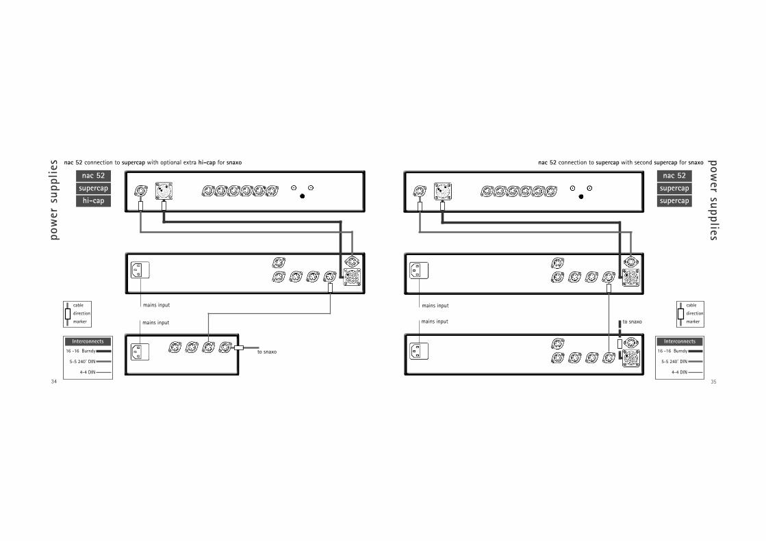
35
power supplies
nac 52 connection to supercap with second supercap for snaxo
nac 52 supercap supercap
pow
er s
uppl
ies nac 52 connection to supercap with optional extra hi-cap for snaxo
supercaphi-cap
nac 52
34
to snaxo
to snaxo
16 -16 Burndy
5-5 240˚ DIN
4-4 DIN
Interconnects
cable
direction
marker
16 -16 Burndy
5-5 240˚ DIN
4-4 DIN
Interconnects
cable
direction
markermains input
mains input
mains input
mains input

37
power supplies
nac 82 connection to supercap with extra hi-cap for snaxo
nac 82 supercap hi-cap
pow
er s
uppl
ies nac 82 connection to two hi-caps with extra flatcap 2 for snaxo
36
nac 82hi-cap
napsc
mains inputpower switch
mains input
all link plugs removed
to snaxo
flatcap 2
cable
direction
marker
cable
direction
marker
4-4 DIN
5-5 240˚ DIN
Interconnects
4-4 DIN
5-5 240˚ DIN
Interconnects
for cd5, headline orstageline. Additionalinterconnectsrequired.
napsc
all link plugs removed
to snaxo
mains input
mains input

39
power supplies
nac 112 connection to flatcap 2 with extra flatcap 2 for snaxo, cd5, stageline or headline
nac 112 flatcap 2
pow
er s
uppl
ies nac 82 connection to supercap with extra supercap for snaxo
38
nac 82supercapsupercap
napsc
all link plugs removed
to snaxo
16 -16 Burndy
5-5 240˚ DIN
4-4 DIN
Interconnects
cable
direction
marker to snaxo
cover fitted
for cd5, headline orstageline. Additionalinterconnectsrequired.
cable
direction
marker
4-4 DIN
5-5 240˚ DIN
Interconnects
mains input
mains input
mains inputpower switch
mains inputpower switch

41
active crossovers
snaxo connection to hi-cap from nac 52 and supercap
supercap hi-cap snaxo
acti
ve c
ross
over
s
snaxo 2-4ixo 2
snaxo 3-6
40
1
2 - 4
5 - 7
1
2 - 3
4 - 5
1 2 3
o/p2nc
o/p1-ve
ixo sockets 1 & 2
ch1nc
ch2-ve
ixo socket 3
o/p1nc
-ve
o/p2
3-6 sockets 5 - 7
o/p2nc
-ve
o/p1
2-4 sockets 4 & 5
o/p1nc
-ve
-ve
3-6 sockets 2 - 4
-venc
-ve
o/p1
2-4 sockets 2 & 3
+vech1
ch2
-ve+ve
3-6/2-4 socket 1
mains inputpower switch
link plug fitted
cable
direction
marker
4-4 DIN
5-5 240˚ DIN
Interconnects
to nac 52
level adjustmentnoteconnections for the snaxo 3-6 and snaxo 2-4are the same.
mains input
mains input

43
active crossovers
snaxo connection to hi-cap from nac 82, 102, 112 and hi-cap
hi-cap
snaxo hi-cap
acti
ve c
ross
over
s snaxo connection to supercap from nac 52 and supercap
supercapsupercap
snaxo
42
to nac 52
link plug removed
cable
direction
marker
4-4 DIN
17 -17 Burndy
Interconnects
to preamp
link plug fitted
noteIf a nac 82 is powered by two hi-caps theconnections are the same (from 82 hi-capnumber one).
hi-caps earlier than serial number 105469must be connected together via the secondset of sockets rather than the third - asillustrated by the dotted connection cable.
cable
direction
marker
4-4 DIN
5-5 240˚ DIN
Interconnects
mains input
mains input
mains input
mains input

45
active crossovers
supercap supercap
snaxo
acti
ve c
ross
over
s
hi-capsnaxo
supercap
44
to nac 82
link plug fitted
snaxo connection to hi-cap from nac 82 and supercap
cable
direction
marker
4-4 DIN
5-5 240˚ DIN
Interconnects
to nac 82
link plug removed
snaxo connection to supercap from nac 82 and supercap
cable
direction
marker
4-4 DIN
17 -17 Burndy
Interconnects
mains input mains input
mains inputmains input

47
active crossovers
nap 500 nap 500
acti
ve c
ross
over
s snaxo 3-6 connection to three nap 500
snaxo 3-6nap 500
46
ch1 bass green ch1 mid red
ch2 bass green
ch2 mid red
ch2 treblered
ch1 treblegreen
4 DIN/XLR Red
4 DIN/XLR Green
Interconnects
- ++ - - ++ -
- ++ -

4948
active crossovers
nap 500
acti
ve c
ross
over
s sanxo 2-4 connection to two nap 500
snaxo 2-4nap 500
ch1 bass green ch1 treble red
ch2 bass green
ch2 treble red
4 DIN/XLR Red
4 DIN/XLR Green
Interconnects
- ++ - - ++ -

51
active crossovers
nap 135 nap 135 nap 135
acti
ve c
ross
over
s snaxo 3-6 connection to six nap 135
nap 135nap 135
snaxo 3-6nap 135
50
4 DIN/XLR Red
4 DIN/XLR Green
Interconnects
ch1 bass green ch1 midred
ch2 midred
ch2 bass green
ch1 treble green ch2 treblered
- +
- +
- +
- +
- +
- +
mains input
mains input
mains input mains input
mains input
mains input
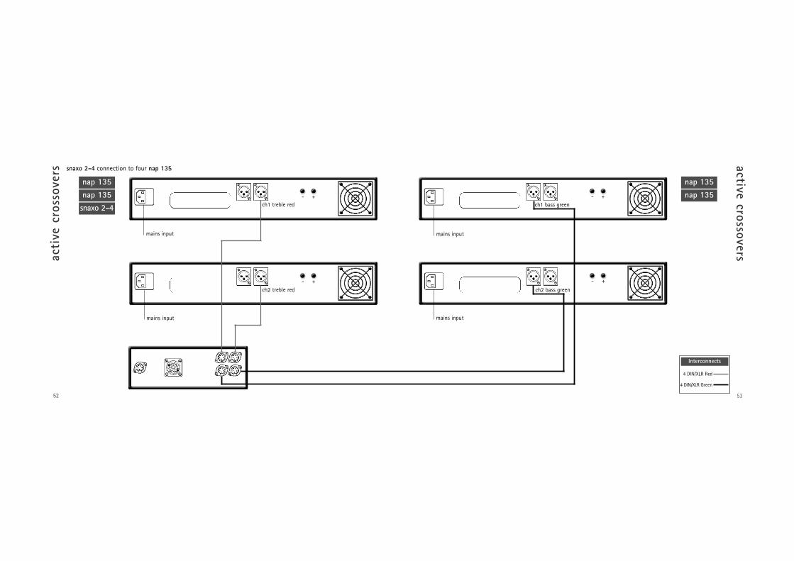
53
active crossoversacti
ve c
ross
over
s
52
nap 135 nap 135
snaxo 2-4 connection to four nap 135
nap 135nap 135
snaxo 2-4
4 DIN/XLR Red
4 DIN/XLR Green
Interconnects
ch1 treble red ch1 bass green
ch2 bass greench2 treble red
- + - +
- +- +
mains input
mains input
mains input
mains input

55
active crossovers
snaxo 2-4 connection to two nap 250
snaxo 2-4 nap 250 nap 250
acti
ve c
ross
over
s snaxo 3-6 connection to three nap 250
54
nap 250snaxo 3-6
nap 250nap 250
4 DIN/XLR White
Interconnects
4 DIN/XLR White
Interconnects
ch1 bass ch1 mid
ch2 bass ch2 mid
ch1 treble ch2 treble
ch1 bass ch1 treble
ch2 bass ch2 treble
mains input
mains input
mains input
mains input
- ++ -
- ++ -
- ++ - - ++ -
- ++ -
- ++ - - ++ -

57
active crossovers
ixo 2 connection to two nap 150
acti
ve c
ross
over
s nac 112 connection to flatcap 2 and ixo 2
flatcap 2ixo 2
nac 112
56
cover fitted left right
for cd5, headline orstageline. Additionalinterconnectsrequired.
cable
direction
marker cable
direction
marker
4-4 DIN
5-5 240˚ DIN
Interconnects
ch1 bass ch1 treble
ch2 bass ch2 treble
ixo 2 nap 150 nap 150
4-4 DIN
Interconnects
power switch
mains input
mains input
power switch
power switch
mains input
mains input
power switch
mains inputpower switch
- ++ -
- ++ -

58
Naim Audio Southampton Road Salisbury England SP1 2LNTel: +44 (0)1722 332266 www.naim-audio.com
OWNCG • issue 2 • August 2001


