www.caddyindustrial.com.au
Contents
Corrosion P Protection
BLACK Plain Oil Finish1 Electro plated zinc
The anti-corrosion protection consists of an electrolytically applied zinc coating with a layer thickness of 8-15 micron or an equivalent treatment. This protection will withstand 90 hours saltspray test to DIN 50021, ISO/R 1456-1970, ASTM® B 117-90.
This fi nish is intended for indoor use in non-corrosive environments only.
2 Stainless steelSpring steel stainless steel fasteners are made of austenitic stainless steel type X12 Cr Ni 17-7 (AISI 302, Standard no. 1.4310, according to DIN 17224).
Other stainless steel products are made of austenitic stainless steel type X5 Cr Ni 18-10 (AISI 304, Standard no. 1.4301). On special request the following parts, C20, C30, C45, 5000, 6000 and all CR clamps, can also be produced in austenitic stainless steel type X6 Cr Ni Mo 17122 (AISI 316, Standard no. 1.4571).
ERICO - Fixoband and buckles are made of austenitic stainless steel type AISI 201.
3 Hot dip galvanised zincProtection against corrosion is provided by hot dip galvanising in accordance with DIN 50976-tZn-0, BS 729, NFA 91-121 and NEN 1275.
The zinc layer thickness is 50-70 micron (equivalent to 350-500 g/m2).
4 ERICO plated zinc (mechanically deposited zinc)The anti-corrosion protection consists of a coating of mechanically deposited zinc with a layer thickness of approx. 25 micron, a chromate passivator and a transparent sealer.
The total system provides high levels of protection against white corrosion and red rust, according to ASTM B 695-90, AFNOR A91-203 and draft standards BS (GB) and UNI (Italy).
The corrosion resistance of the system is 500 hours against red rust for a saltspray test as per DIN 50021, ISO/R 1456-1970 and ASTM B 117-90.
5 Nylon6 Lacquered
The corrosion resistance of these layers is minimum 192 hours for a salt spray test as per DIN 50021, ISO/R 1456-1970 and ASTM B117-74.
7 CADDY® COATThis fi nish consists of a two part coating, a base coat and a topcoat.
The base coat of zinc phosphate aids in corrosion resistance and increases the adhesion of the topcoat.
The organic topcoat provides superior corrosion resistance. The system was evaluated in a 500 hour saltspray test per ASTM D610. The testing conformed to ASTM B117.
Spring steel fasteners are for indoor use in non-corrosive environments. Mild steel fasteners can be used outdoors in humid or mildly corrosive environments.
8 Polyurethane (PU)9 Polyamide (PA)10 Polyvinylchloride (PVC)ASTM is a registered trademark of ASTM International
1 Electrical Supports SystemsFlange Clamps .............................................................................. Page 1Purlin/Beam Clamps & Mounting Plates .......................Page 2-4Beam & Conduit Clamps .......................................................... Page 5Steel Conduit & Couplings ....................................................... Page 6Wedge Nuts, Grommets & T-Bar Hangers ........................ Page 7Angle Brackets, Rod Hangers, ISN Nuts ............................. Page 8Speed Link ..................................................................................... Page 9Cable Cat ............................................................................... Page 10-12Perforated Cable Tray & Accessories .................................Page 13Ladder-Tray & Accessories .............................................. Page 14-21Cable Ladder ........................................................................Page 22-24Cable Mesh & Cable Duct .....................................................Page 25Covers & Barrier Strip...............................................................Page 26
2 Pipe SupportsInsulated Pipe Clamps ZP & SS .................................... Page 27-28Sprinkler Supports ....................................................................Page 29Channel Clips ..............................................................................Page 30Cush-A-Clamps & Super-Klip ................................................Page 31Heavy Duty U Bolt Guide & Grip ........................................Page 32Medium Duty Clamps, Saddles & U Bolts ...............Page 33-34Clevis, Universal Joints, Isolation Barrier & Acc .............Page 35Stabil D 3-G Pipe Clamps .....................................................Page 36Riser Clamps & Slide Sets ......................................................Page 37
3 Sikla Support SystemsPressix Channel ..........................................................................Page 38Pressix End Caps, T-Head Bolts & Holding Brackets ...Page 39Pressix Channel Nuts & Speed Nuts ................................ Page 40Pressix BlockSets & Blocks ....................................................Page 41Pressix Cantilever Brackets & Angle Connectors ..........Page 42Pressix Fitting Sets Beam Clamps .....................................Page 43Framo 80 Gallery ..................................................................... Page 44Framo 80 Beam Section .......................................................Page 45Framo 80 Cantilever Brackets ..............................................Page 46Framo 80 Beam Brackets .....................................................Page 47Framo 80 End Supports ................................................ Page 48-49Framo 80 Channel Adapters & FLS Screws ....................Page 50Framo 80 U Holder & End Caps ........................................Page 51
4 Lindapter Steelwork Fixings Type A & Type B .....................................Page 52Accessories for Type A & Type B .........................................Page 53Steelwork Fixings Type AF ......................................................Page 54Accessories for Type AF ..........................................................Page 55Steelwork Fixings Type LR & Accessories .........................page 56Steelwork Fixings Type BR & Type F9................................Page 57Bolt Length Calculations .........................................................Page 58Typical Applications .......................................................... Page 59-60Cavity Fixings – Hollo Bolts ...................................................Page 61Cavity Fixings – Hollo Bolts – Load Tables ..............Page 62-63Floor Fasteners Type FF & Type GF ................................... Page 64
5 Channel & Accessories Channel Profi les & Cantilever Brackets .............................Page 65Channel Joiners & Angle ....................................................... page 66Channel Nuts, Caps, Closure Strip, Trolleys ....................Page 67Channel Fittings .........................................................................Page 68
6 Rod, Anchors & AccessoriesVertigo Hangers .........................................................................Page 69Masonry Fasteners ....................................................................Page 70Threaded Rod, Nuts, Washers .............................................page 71Set Screws, Cup Head Bolts, Screws ................................Page 72Tek Screws & Drill Bits .............................................................Page 73Rivets ............................................................................................Page 74Rod Cutter ................................................................................... Page75

Phone: 08 9475 08551
1. Electrical Supports
H-CLIPPart # / Description A
mmØ
mmBox
Quantity
Corrosion Protection – 7
312H4 2-3 N/A 100
314H24 3-8 N/A 100
314H58 8-14 N/A 100
314H912 14-20 N/A 100
H-ST CLIPPart # / Description A
mmØ
mmBox
Quantity
Corrosion Protection – 7
312H4-ST3 2-3 N/A 100
314H24-ST3 3-8 N/A 100
314H58-ST3 8-14 N/A 100
314H912-ST3 14-20 N/A 100
H-CT CLIPPart # / Description A
mmØ
mmBox
Quantity
Corrosion Protection – 7
312H4CT 2-3 N/A 100
314H24CT 3-8 N/A 100
314H58CT 8-14 N/A 100
314H912CT 14-20 N/A 100
H-TI/T CLIPPart # / Description A
mmØ
mmBox
Quantity
Corrosion Protection – 7
31M6TI4 2-3 M6 100
31M6TI24 3-8 M6 100
31M6TI58 8-14 M6 100
31M6TI912 14-20 M6 100
31M8TI4 2-3 M8 100
31M8TI24 3-8 M8 100
31M8TI58 8-14 M8 100
31M8TI912 14-20 M8 100
31M10TI4 2-3 M10 100
31M10TI24 3-8 M10 100
31M10TI58 8-14 M10 100
31M10TI912 14-20 M10 100
www.caddyindustrial.com.au 2
1. Electrical Supports
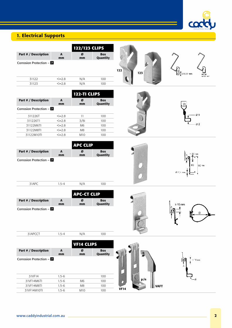
122/123 CLIPS
122123
Part # / Description Amm
Ømm
Box Quantity
Corrosion Protection – 7
31122 <=2.8 N/A 100
31123 <=2.8 N/A 100
122-TI CLIPSPart # / Description A
mmØ
mmBox
Quantity
Corrosion Protection – 7
311226T <=2.8 11 100
311226T1 <=2.8 3/8i 100
31122M6TI <=2.8 M6 100
31122M8TI <=2.8 M8 100
31122M10TI <=2.8 M10 100
APC CLIPPart # / Description A
mmØ
mmBox
Quantity
Corrosion Protection – 7
31APC 1.5-4 N/A 100
APC-CT CLIPPart # / Description A
mmØ
mmBox
Quantity
Corrosion Protection – 7
31APCCT 1.5-4 N/A 100
VF14 CLIPS
VF14VAFT
p/n
Part # / Description Amm
Ømm
Box Quantity
Corrosion Protection – 7
31VF14 1.5-6 100
31VF14M6TI 1.5-6 M6 100
31VF14M8TI 1.5-6 M8 100
31VF14M10TI 1.5-6 M10 100
Phone: 08 9475 08553
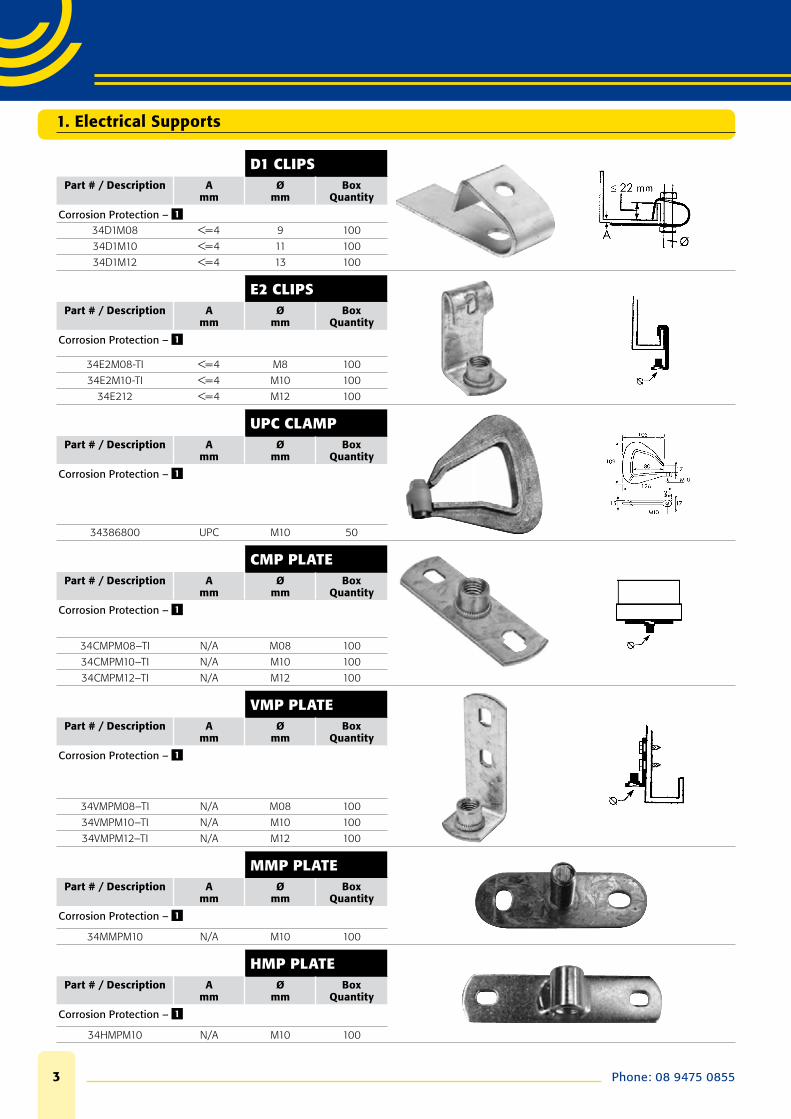
D1 CLIPSPart # / Description A
mmØ
mmBox
Quantity
Corrosion Protection – 1
34D1M08 <=4 9 100
34D1M10 <=4 11 100
34D1M12 <=4 13 100
E2 CLIPSPart # / Description A
mmØ
mmBox
Quantity
Corrosion Protection – 1
34E2M08-TI <=4 M8 100
34E2M10-TI <=4 M10 100
34E212 <=4 M12 100
UPC CLAMPPart # / Description A
mmØ
mmBox
Quantity
Corrosion Protection – 1
34386800 UPC M10 50
CMP PLATEPart # / Description A
mmØ
mmBox
Quantity
Corrosion Protection – 1
34CMPM08–TI N/A M08 100
34CMPM10–TI N/A M10 100
34CMPM12–TI N/A M12 100
VMP PLATEPart # / Description A
mmØ
mmBox
Quantity
Corrosion Protection – 1
34VMPM08–TI N/A M08 100
34VMPM10–TI N/A M10 100
34VMPM12–TI N/A M12 100
MMP PLATEPart # / Description A
mmØ
mmBox
Quantity
Corrosion Protection – 1
34MMPM10 N/A M10 100
HMP PLATEPart # / Description A
mmØ
mmBox
Quantity
Corrosion Protection – 1
34HMPM10 N/A M10 100
1. Electrical Supports
www.caddyindustrial.com.au 4
1. Electrical Supports
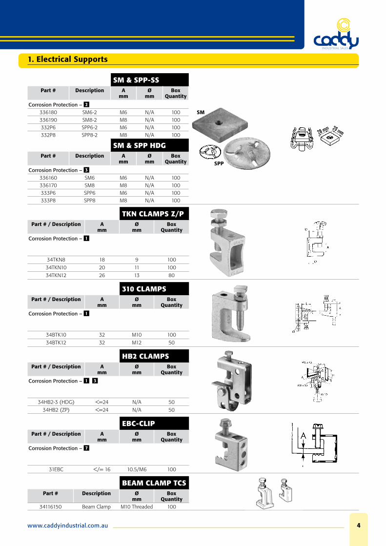
SM & SPP-SS
SM
SPP
Part # Description Amm
Ømm
Box Quantity
Corrosion Protection – 2
336180 SM6-2 M6 N/A 100336190 SM8-2 M8 N/A 100332P6 SPP6-2 M6 N/A 100332P8 SPP8-2 M8 N/A 100
SM & SPP HDGPart # Description A
mmØ
mmBox
Quantity
Corrosion Protection – 3
336160 SM6 M6 N/A 100336170 SM8 M8 N/A 100333P6 SPP6 M6 N/A 100333P8 SPP8 M8 N/A 100
TKN CLAMPS Z/PPart # / Description A
mmØ
mmBox
Quantity
Corrosion Protection – 1
34TKN8 18 9 100
34TKN10 20 11 100
34TKN12 26 13 80
310 CLAMPSPart # / Description A
mmØ
mmBox
Quantity
Corrosion Protection – 1
34BTK10 32 M10 100
34BTK12 32 M12 50
HB2 CLAMPSPart # / Description A
mmØ
mmBox
Quantity
Corrosion Protection – 1 3
34HB2-3 (HDG) <=24 N/A 50
34HB2 (ZP) <=24 N/A 50
EBC-CLIPPart # / Description A
mmØ
mmBox
Quantity
Corrosion Protection – 7
31EBC </= 16 10.5/M6 100
BEAM CLAMP TCSPart # Description Ø
mmBox
Quantity34116150 Beam Clamp M10 Threaded 100
Phone: 08 9475 08555
1. Electrical Supports
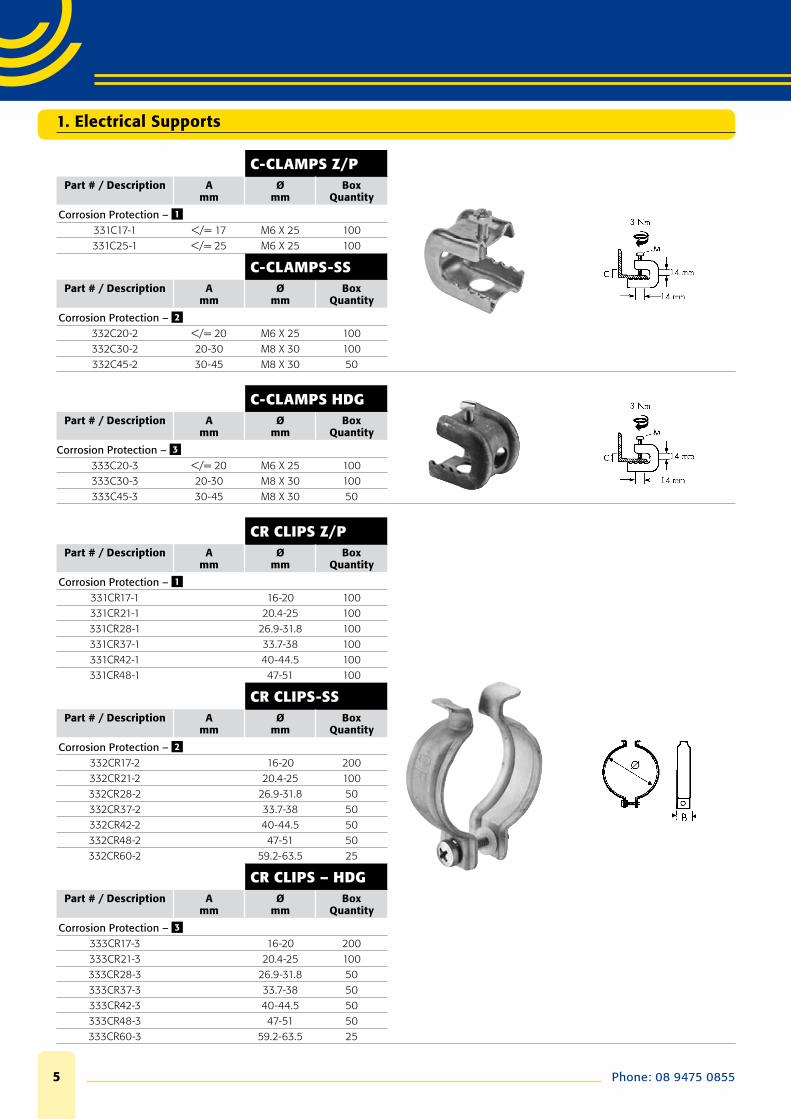
C-CLAMPS Z/PPart # / Description A
mmØ
mmBox
Quantity
Corrosion Protection – 1
331C17-1 </= 17 M6 X 25 100331C25-1 </= 25 M6 X 25 100
C-CLAMPS-SSPart # / Description A
mmØ
mmBox
Quantity
Corrosion Protection – 2
332C20-2 </= 20 M6 X 25 100332C30-2 20-30 M8 X 30 100332C45-2 30-45 M8 X 30 50
C-CLAMPS HDGPart # / Description A
mmØ
mmBox
Quantity
Corrosion Protection – 3
333C20-3 </= 20 M6 X 25 100333C30-3 20-30 M8 X 30 100333C45-3 30-45 M8 X 30 50
CR CLIPS Z/PPart # / Description A
mmØ
mmBox
Quantity
Corrosion Protection – 1
331CR17-1 16-20 100331CR21-1 20.4-25 100331CR28-1 26.9-31.8 100331CR37-1 33.7-38 100331CR42-1 40-44.5 100331CR48-1 47-51 100
CR CLIPS-SSPart # / Description A
mmØ
mmBox
Quantity
Corrosion Protection – 2
332CR17-2 16-20 200332CR21-2 20.4-25 100332CR28-2 26.9-31.8 50332CR37-2 33.7-38 50332CR42-2 40-44.5 50332CR48-2 47-51 50332CR60-2 59.2-63.5 25
CR CLIPS – HDGPart # / Description A
mmØ
mmBox
Quantity
Corrosion Protection – 3
333CR17-3 16-20 200333CR21-3 20.4-25 100333CR28-3 26.9-31.8 50333CR37-3 33.7-38 50333CR42-3 40-44.5 50333CR48-3 47-51 50333CR60-3 59.2-63.5 25
www.caddyindustrial.com.au 6
1. Electrical Supports
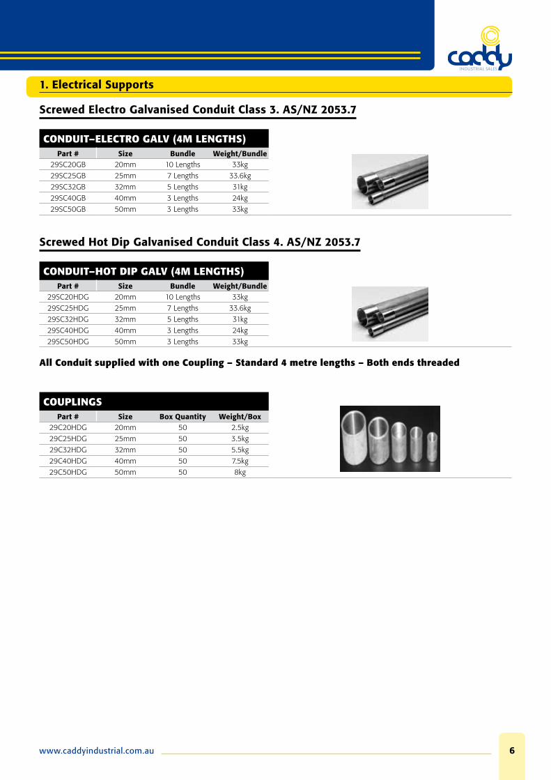
Screwed Electro Galvanised Conduit Class 3. AS/NZ 2053.7
CONDUIT–ELECTRO GALV (4M LENGTHS)Part # Size Bundle Weight/Bundle
29SC20GB 20mm 10 Lengths 33kg
29SC25GB 25mm 7 Lengths 33.6kg
29SC32GB 32mm 5 Lengths 31kg
29SC40GB 40mm 3 Lengths 24kg
29SC50GB 50mm 3 Lengths 33kg
Screwed Hot Dip Galvanised Conduit Class 4. AS/NZ 2053.7
CONDUIT–HOT DIP GALV (4M LENGTHS)Part # Size Bundle Weight/Bundle
29SC20HDG 20mm 10 Lengths 33kg
29SC25HDG 25mm 7 Lengths 33.6kg
29SC32HDG 32mm 5 Lengths 31kg
29SC40HDG 40mm 3 Lengths 24kg
29SC50HDG 50mm 3 Lengths 33kg
All Conduit supplied with one Coupling – Standard 4 metre lengths – Both ends threaded
COUPLINGSPart # Size Box Quantity Weight/Box
29C20HDG 20mm 50 2.5kg
29C25HDG 25mm 50 3.5kg
29C32HDG 32mm 50 5.5kg
29C40HDG 40mm 50 7.5kg
29C50HDG 50mm 50 8kg
Phone: 08 9475 08557
1. Electrical Supports
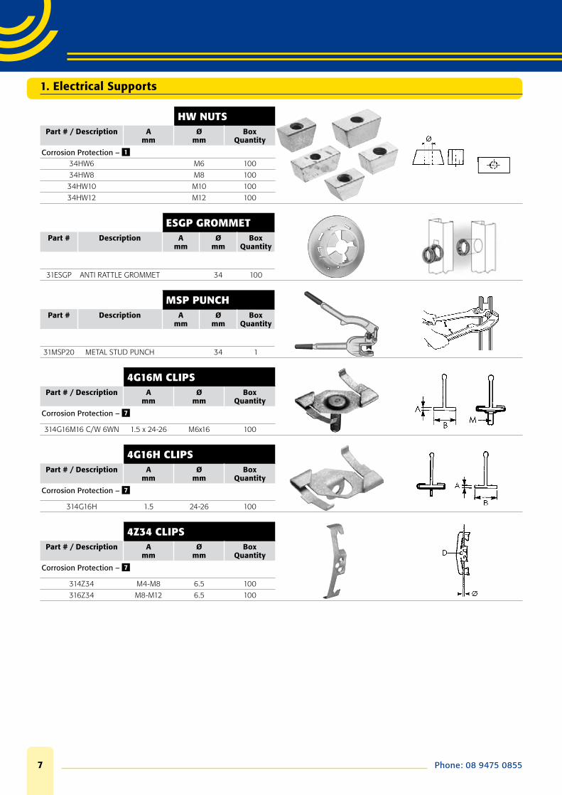
HW NUTSPart # / Description A
mmØ
mmBox
Quantity
Corrosion Protection – 1
34HW6 M6 100
34HW8 M8 100
34HW10 M10 100
34HW12 M12 100
ESGP GROMMETPart # Description A
mmØ
mmBox
Quantity
31ESGP ANTI RATTLE GROMMET 34 100
MSP PUNCHPart # Description A
mmØ
mmBox
Quantity
31MSP20 METAL STUD PUNCH 34 1
4G16M CLIPSPart # / Description A
mmØ
mmBox
Quantity
Corrosion Protection – 7
314G16M16 C/W 6WN 1.5 x 24-26 M6x16 100
4G16H CLIPSPart # / Description A
mmØ
mmBox
Quantity
Corrosion Protection – 7
314G16H 1.5 24-26 100
4Z34 CLIPSPart # / Description A
mmØ
mmBox
Quantity
Corrosion Protection – 7
314Z34 M4-M8 6.5 100
316Z34 M8-M12 6.5 100

www.caddyindustrial.com.au 8
6Z34-CTSPart # / Description A
mmØ
mmBox
Quantity
Corrosion Protection – 7
346Z34CTS M8-M12 100
ANGLE BRACKETSPart # Description A
mmØ
mmBox
Quantity
Corrosion Protection – 3
34AB77 3 x 25 ANGLE 7 7 100
34AB97 3 x 25 ANGLE 7 9 100
34AB711 3 x 25 ANGLE 7 11 100
34AB1111 3 x 25 ANGLE 11 11 100
OFFSET BRACKETSPart # Description A
mmØ
mmBox
Quantity
Corrosion Protection – 7
31AO 3 x 20 OFFSET 7 7 100
TI/T CLIPSPart # / Description A
mmØ
mmBox
Quantity
Corrosion Protection – 7
31M6TI M6 100
31M8TI M8 100
31M10TI M10 100
B-TI/T CLIPSPart # / Description A
mmØ
mmBox
Quantity
Corrosion Protection – 7
31M6TIB M6 100
31M8TIB M8 100
31M10TIB M10 100
316TB 11 100
ISN NUTPart # / Description A
mmØ
mmBox
Quantity
Corrosion Protection – 1
36ISNM06 ISN M6 M6 50
36ISNM08 ISN M8 M8 50
36ISNM10 ISN M10 M10 50
1. Electrical Supports
Phone: 08 9475 08559
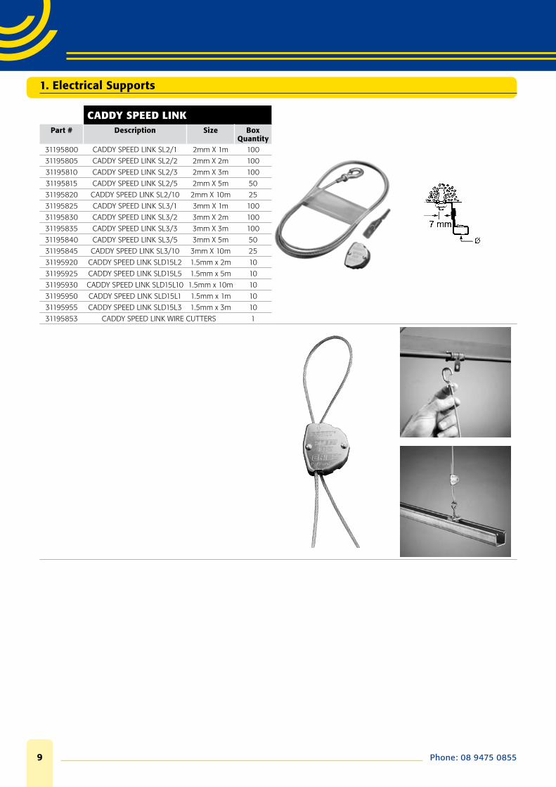
CADDY SPEED LINKPart # Description Size Box
Quantity31195800 CADDY SPEED LINK SL2/1 2mm X 1m 100
31195805 CADDY SPEED LINK SL2/2 2mm X 2m 100
31195810 CADDY SPEED LINK SL2/3 2mm X 3m 100
31195815 CADDY SPEED LINK SL2/5 2mm X 5m 50
31195820 CADDY SPEED LINK SL2/10 2mm X 10m 25
31195825 CADDY SPEED LINK SL3/1 3mm X 1m 100
31195830 CADDY SPEED LINK SL3/2 3mm X 2m 100
31195835 CADDY SPEED LINK SL3/3 3mm X 3m 100
31195840 CADDY SPEED LINK SL3/5 3mm X 5m 50
31195845 CADDY SPEED LINK SL3/10 3mm X 10m 25
31195920 CADDY SPEED LINK SLD15L2 1.5mm x 2m 10
31195925 CADDY SPEED LINK SLD15L5 1.5mm x 5m 10
31195930 CADDY SPEED LINK SLD15L10 1.5mm x 10m 10
31195950 CADDY SPEED LINK SLD15L1 1.5mm x 1m 10
31195955 CADDY SPEED LINK SLD15L3 1.5mm x 3m 10
31195853 CADDY SPEED LINK WIRE CUTTERS 1
1. Electrical Supports
www.caddyindustrial.com.au 10
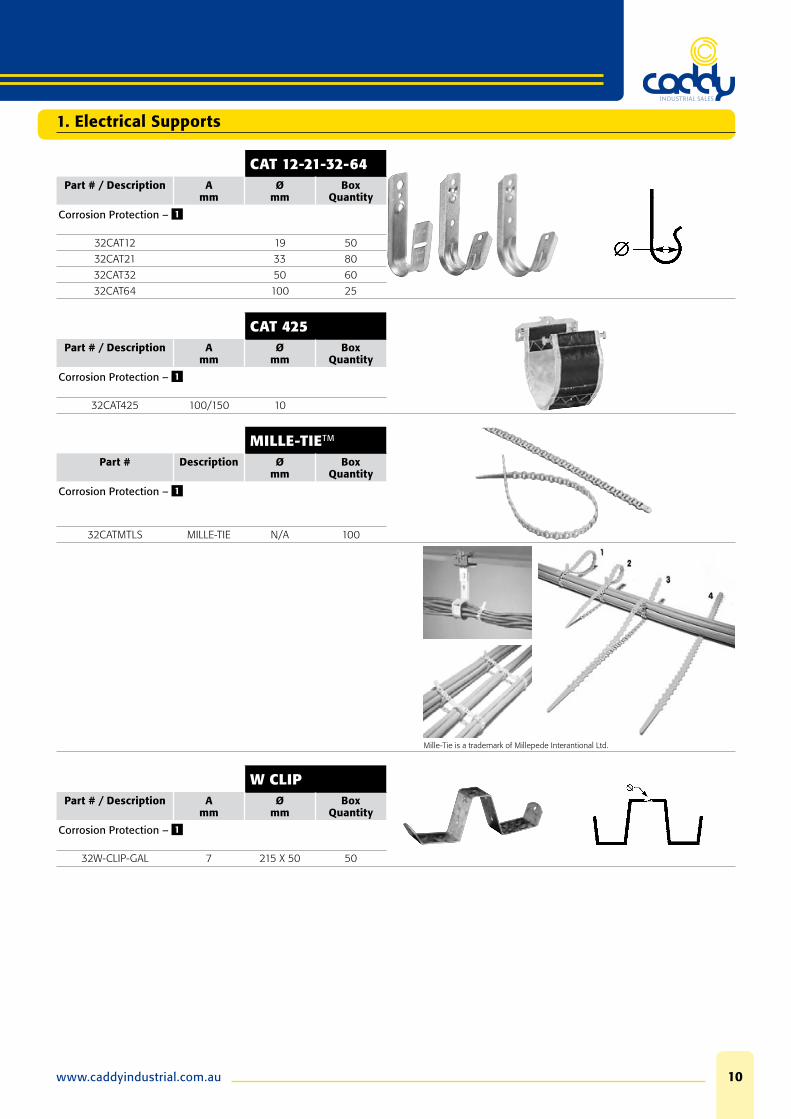
CAT 12-21-32-64
Part # / Description Amm
Ømm
Box Quantity
Corrosion Protection – 1
32CAT12 19 50
32CAT21 33 80
32CAT32 50 60
32CAT64 100 25
CAT 425Part # / Description A
mmØ
mmBox
Quantity
Corrosion Protection – 1
32CAT425 100/150 10
MILLE-TIETM
Part # Description Ømm
Box Quantity
Corrosion Protection – 1
32CATMTLS MILLE-TIE N/A 100
Mille-Tie is a trademark of Millepede Interantional Ltd.
W CLIPPart # / Description A
mmØ
mmBox
Quantity
Corrosion Protection – 1
32W-CLIP-GAL 7 215 X 50 50
1. Electrical Supports
Phone: 08 9475 085511
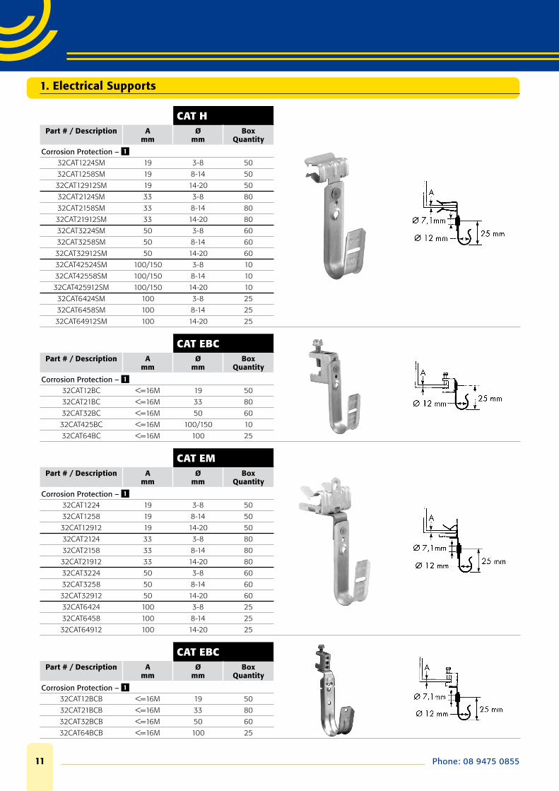
CAT HPart # / Description A
mmØ
mmBox
Quantity
Corrosion Protection – 1
32CAT1224SM 19 3-8 50
32CAT1258SM 19 8-14 50
32CAT12912SM 19 14-20 50
32CAT2124SM 33 3-8 80
32CAT2158SM 33 8-14 80
32CAT21912SM 33 14-20 80
32CAT3224SM 50 3-8 60
32CAT3258SM 50 8-14 60
32CAT32912SM 50 14-20 60
32CAT42524SM 100/150 3-8 10
32CAT42558SM 100/150 8-14 10
32CAT425912SM 100/150 14-20 10
32CAT6424SM 100 3-8 25
32CAT6458SM 100 8-14 25
32CAT64912SM 100 14-20 25
CAT EBCPart # / Description A
mmØ
mmBox
Quantity
Corrosion Protection – 1
32CAT12BC <=16M 19 50
32CAT21BC <=16M 33 80
32CAT32BC <=16M 50 60
32CAT425BC <=16M 100/150 10
32CAT64BC <=16M 100 25
CAT EMPart # / Description A
mmØ
mmBox
Quantity
Corrosion Protection – 1
32CAT1224 19 3-8 50
32CAT1258 19 8-14 50
32CAT12912 19 14-20 50
32CAT2124 33 3-8 80
32CAT2158 33 8-14 80
32CAT21912 33 14-20 80
32CAT3224 50 3-8 60
32CAT3258 50 8-14 60
32CAT32912 50 14-20 60
32CAT6424 100 3-8 25
32CAT6458 100 8-14 25
32CAT64912 100 14-20 25
CAT EBCPart # / Description A
mmØ
mmBox
Quantity
Corrosion Protection – 1
32CAT12BCB <=16M 19 50
32CAT21BCB <=16M 33 80
32CAT32BCB <=16M 50 60
32CAT64BCB <=16M 100 25
1. Electrical Supports
www.caddyindustrial.com.au 12
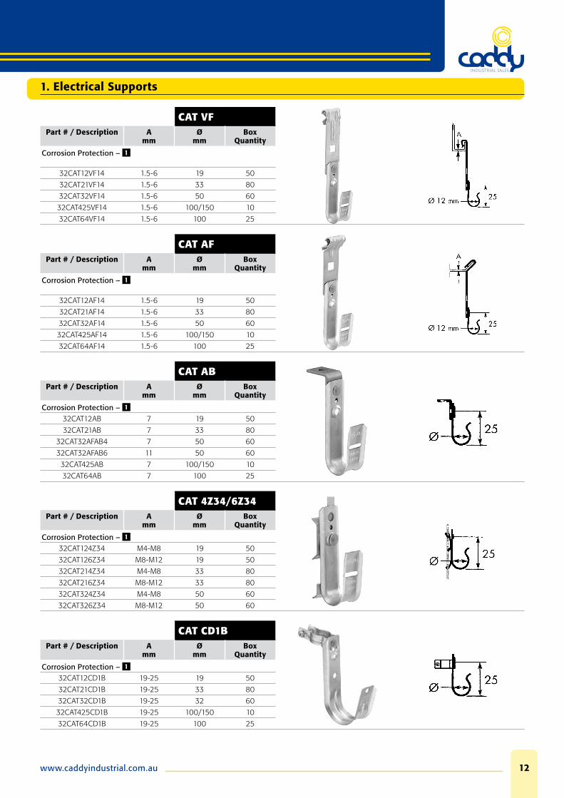
CAT VFPart # / Description A
mmØ
mmBox
Quantity
Corrosion Protection – 1
32CAT12VF14 1.5-6 19 50
32CAT21VF14 1.5-6 33 80
32CAT32VF14 1.5-6 50 60
32CAT425VF14 1.5-6 100/150 10
32CAT64VF14 1.5-6 100 25
CAT AFPart # / Description A
mmØ
mmBox
Quantity
Corrosion Protection – 1
32CAT12AF14 1.5-6 19 50
32CAT21AF14 1.5-6 33 80
32CAT32AF14 1.5-6 50 60
32CAT425AF14 1.5-6 100/150 10
32CAT64AF14 1.5-6 100 25
CAT ABPart # / Description A
mmØ
mmBox
Quantity
Corrosion Protection – 1
32CAT12AB 7 19 50
32CAT21AB 7 33 80
32CAT32AFAB4 7 50 60
32CAT32AFAB6 11 50 60
32CAT425AB 7 100/150 10
32CAT64AB 7 100 25
CAT 4Z34/6Z34Part # / Description A
mmØ
mmBox
Quantity
Corrosion Protection – 1
32CAT124Z34 M4-M8 19 50
32CAT126Z34 M8-M12 19 50
32CAT214Z34 M4-M8 33 80
32CAT216Z34 M8-M12 33 80
32CAT324Z34 M4-M8 50 60
32CAT326Z34 M8-M12 50 60
CAT CD1BPart # / Description A
mmØ
mmBox
Quantity
Corrosion Protection – 1
32CAT12CD1B 19-25 19 50
32CAT21CD1B 19-25 33 80
32CAT32CD1B 19-25 32 60
32CAT425CD1B 19-25 100/150 10
32CAT64CD1B 19-25 100 25
1. Electrical Supports
Phone: 08 9475 085513
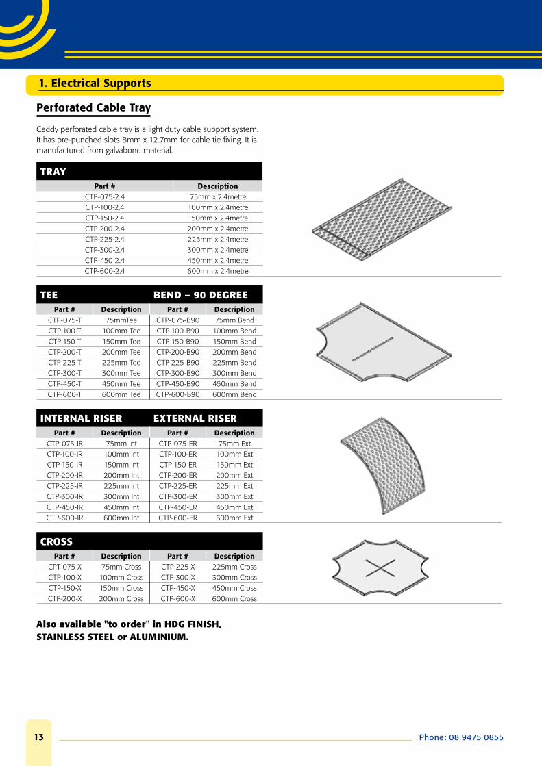
Perforated Cable Tray
Caddy perforated cable tray is a light duty cable support system. It has pre-punched slots 8mm x 12.7mm for cable tie fi xing. It is manufactured from galvabond material.
TRAYPart # Description
CTP-075-2.4 75mm x 2.4metreCTP-100-2.4 100mm x 2.4metreCTP-150-2.4 150mm x 2.4metreCTP-200-2.4 200mm x 2.4metreCTP-225-2.4 225mm x 2.4metreCTP-300-2.4 300mm x 2.4metreCTP-450-2.4 450mm x 2.4metreCTP-600-2.4 600mm x 2.4metre
TEE BEND – 90 DEGREEPart # Description Part # Description
CTP-075-T 75mmTee CTP-075-B90 75mm BendCTP-100-T 100mm Tee CTP-100-B90 100mm BendCTP-150-T 150mm Tee CTP-150-B90 150mm BendCTP-200-T 200mm Tee CTP-200-B90 200mm BendCTP-225-T 225mm Tee CTP-225-B90 225mm BendCTP-300-T 300mm Tee CTP-300-B90 300mm BendCTP-450-T 450mm Tee CTP-450-B90 450mm BendCTP-600-T 600mm Tee CTP-600-B90 600mm Bend
INTERNAL RISER EXTERNAL RISERPart # Description Part # Description
CTP-075-IR 75mm Int CTP-075-ER 75mm ExtCTP-100-IR 100mm Int CTP-100-ER 100mm ExtCTP-150-IR 150mm Int CTP-150-ER 150mm ExtCTP-200-IR 200mm Int CTP-200-ER 200mm ExtCTP-225-IR 225mm Int CTP-225-ER 225mm ExtCTP-300-IR 300mm Int CTP-300-ER 300mm ExtCTP-450-IR 450mm Int CTP-450-ER 450mm ExtCTP-600-IR 600mm Int CTP-600-ER 600mm Ext
CROSSPart # Description Part # Description
CPT-075-X 75mm Cross CTP-225-X 225mm CrossCTP-100-X 100mm Cross CTP-300-X 300mm CrossCTP-150-X 150mm Cross CTP-450-X 450mm CrossCTP-200-X 200mm Cross CTP-600-X 600mm Cross
Also available "to order" in HDG FINISH, STAINLESS STEEL or ALUMINIUM.
1. Electrical Supports
www.caddyindustrial.com.au 14
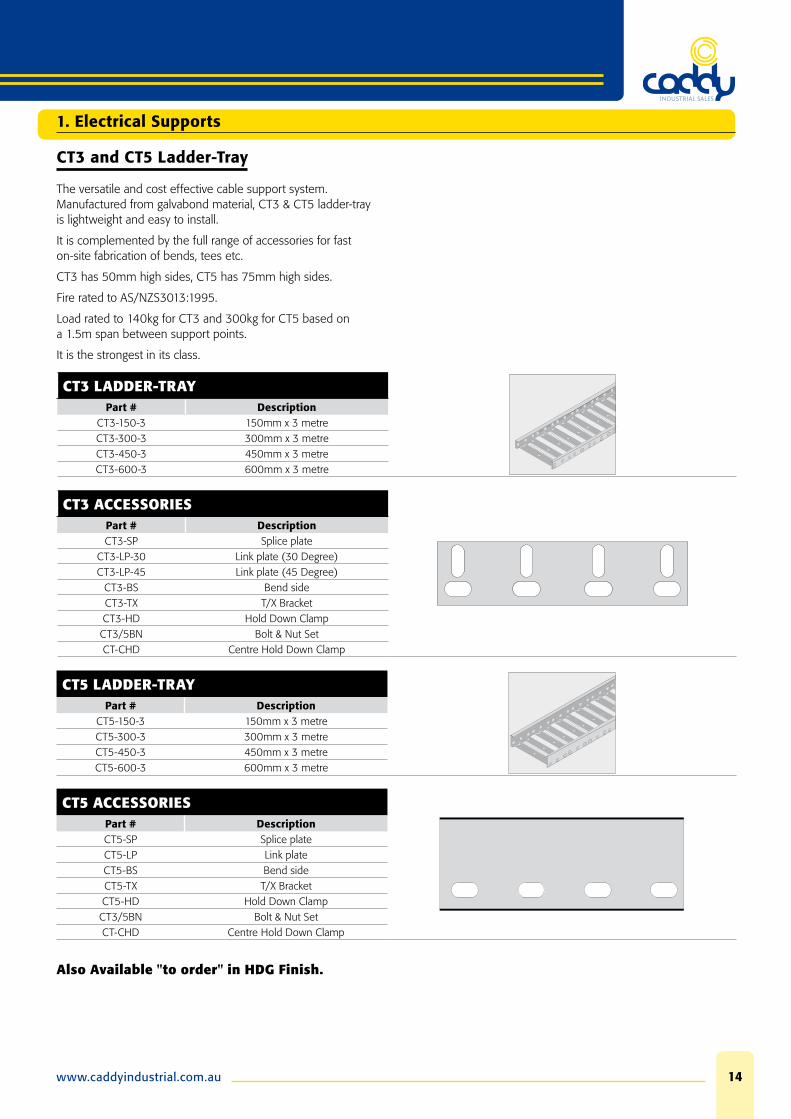
CT3 and CT5 Ladder-Tray
The versatile and cost effective cable support system. Manufactured from galvabond material, CT3 & CT5 ladder-tray is lightweight and easy to install.
It is complemented by the full range of accessories for fast on-site fabrication of bends, tees etc.
CT3 has 50mm high sides, CT5 has 75mm high sides.
Fire rated to AS/NZS3013:1995.
Load rated to 140kg for CT3 and 300kg for CT5 based on a 1.5m span between support points.
It is the strongest in its class.
CT3 LADDER-TRAYPart # Description
CT3-150-3 150mm x 3 metreCT3-300-3 300mm x 3 metreCT3-450-3 450mm x 3 metreCT3-600-3 600mm x 3 metre
CT3 ACCESSORIESPart # DescriptionCT3-SP Splice plate
CT3-LP-30 Link plate (30 Degree)CT3-LP-45 Link plate (45 Degree)
CT3-BS Bend sideCT3-TX T/X BracketCT3-HD Hold Down ClampCT3/5BN Bolt & Nut SetCT-CHD Centre Hold Down Clamp
CT5 LADDER-TRAYPart # Description
CT5-150-3 150mm x 3 metreCT5-300-3 300mm x 3 metreCT5-450-3 450mm x 3 metreCT5-600-3 600mm x 3 metre
CT5 ACCESSORIESPart # DescriptionCT5-SP Splice plateCT5-LP Link plateCT5-BS Bend sideCT5-TX T/X BracketCT5-HD Hold Down ClampCT3/5BN Bolt & Nut SetCT-CHD Centre Hold Down Clamp
Also Available "to order" in HDG Finish.
1. Electrical Supports

Phone: 08 9475 085515
Laddertray
Also Available "to order" in HDG Finish.
1. Electrical Supports

www.caddyindustrial.com.au 16
Laddertray
“WARNING” do not use as a walkway, ladder, or support for personnel.
CT-TI/3-5 CT-TE/3-5 CT3-5/TX
CT-CHD CT3/LP45 AND LP30 CT5/LP45
CT3/SP CT3/BS and CT5/BS CT5/SP
CT3-5 CT3-5 HDB
Also Available "to order" in HDG Finish.
1. Electrical Supports

Phone: 08 9475 085517
Laddertray
CT3 SERIESPart # Description Ø
mmWidth 'W'
CT3/150 STANDARD LENGTH 3 0m 150
CT3/300 STANDARD FINISH GALVANISED 300
CT3/450 CABLE LAYING DEPTH 43mm 450
CT3/600 600
CT5 SERIESPart # Description Ø
mmWidth 'W'
CT5/150 STANDARD LENGTH 3 0m 150
CT5/300 STANDARD FINISH GALVANISED 300
CT5/450 CABLE LAYING DEPTH 68mm 450
CT5/600 600
Also Available "to order" in HDG Finish.
1. Electrical Supports

www.caddyindustrial.com.au 18
Laddertray
TYPICAL OBR BEND
T INTERSECTION
Also Available "to order" in HDG Finish.
1. Electrical Supports

Phone: 08 9475 085519
Laddertray
CROSS INTERSECTION
45º INTERSECTION
Also Available "to order" in HDG Finish.
1. Electrical Supports
www.caddyindustrial.com.au 20
Laddertray
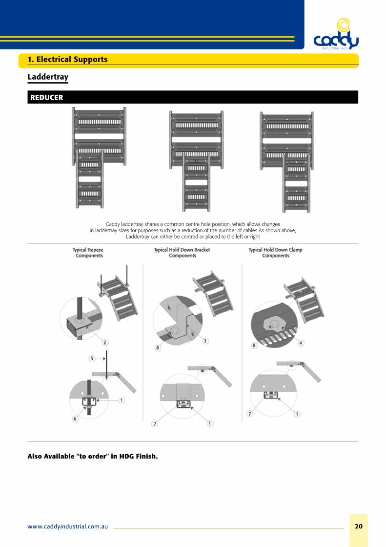
REDUCER
Caddy laddertray shares a common centre hole position, which allows changes in laddertray sizes for purposes such as a reduction of the number of cables As shown above,
Laddertray can either be centred or placed to the left or right
Also Available "to order" in HDG Finish.
1. Electrical Supports
Phone: 08 9475 085521
Laddertray
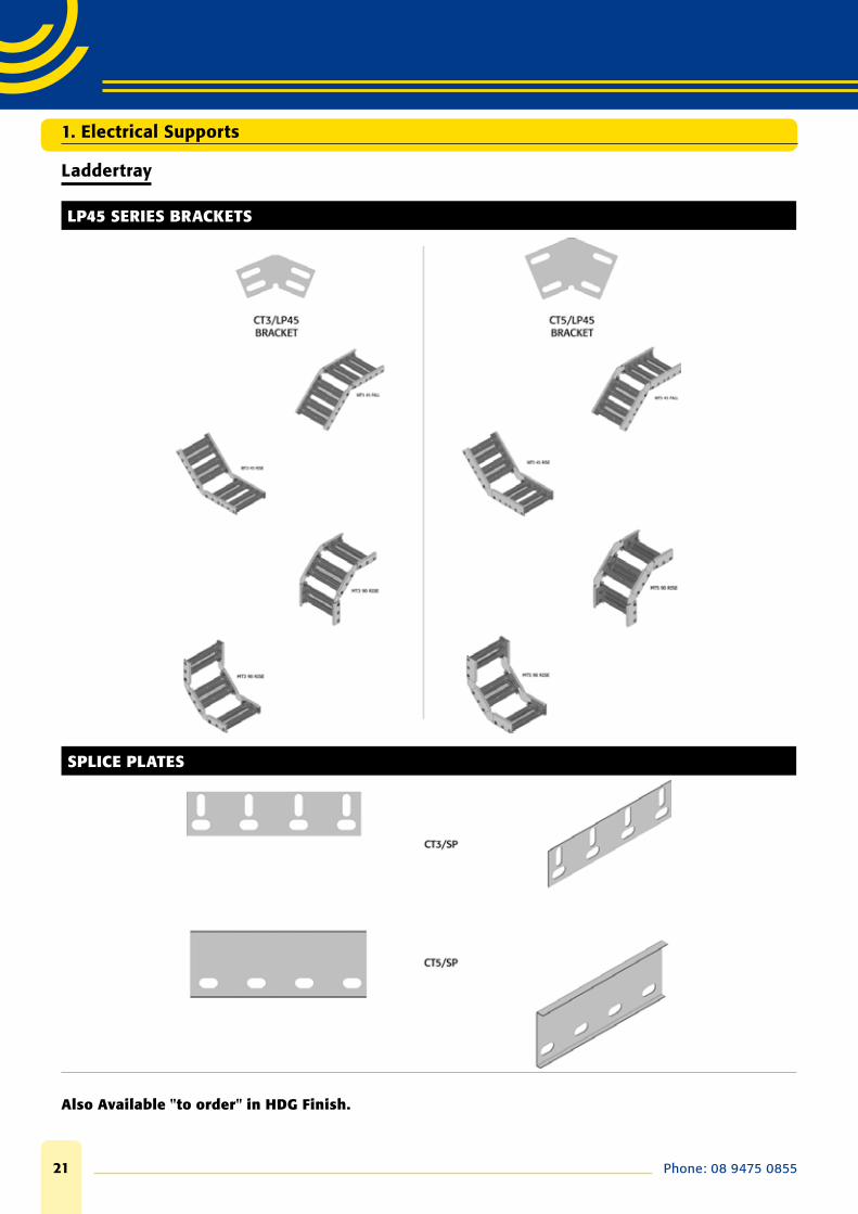
LP45 SERIES BRACKETS
SPLICE PLATES
Also Available "to order" in HDG Finish.
1. Electrical Supports
www.caddyindustrial.com.au 22
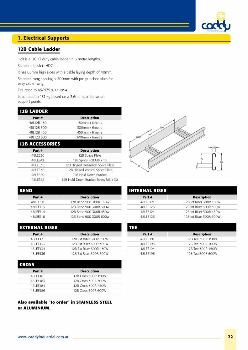
12B Cable Ladder
12B is a LIGHT duty cable ladder in 6 metre lengths.
Standard fi nish is HDG.
It has 65mm high sides with a cable laying depth of 40mm.
Standard rung spacing is 300mm with pre punched slots for easy cable fi xing.
Fire rated to AS/NZS3013:1954.
Load rated to 131 kg based on a 3.6mtr span between support points.
12B LADDERPart # Description
48L12B 150 150mm x 6metre48L12B 300 300mm x 6metre48L12B 450 450mm x 6metre48L12B 600 600mm x 6metre
12B ACCESSORIESPart # Description
48LEE30 12B Splice Plate48LEE42 12B Splice Bolt M8 x 1548LEE35 12B Hinged Horizontal Splice Plate48LEE36 12B Hinged Vertical Splice Plate48LEE50 12B Hold Down Bracket48LEE52 12B Hold Down Bracket Screw M8 x 30
BEND INTERNAL RISERPart # Description Part # Description
48LEE111 12B Bend 900 300R 150w 48LEE121 12B Int Riser 300R 150W48LEE113 12B Bend 900 300R 300w 48LEE123 12B Int Riser 300R 300W48LEE114 12B Bend 900 300R 450w 48LEE124 12B Int Riser 300R 450W48LEE116 12B Bend 900 300R 600w 48LEE126 12B Int Riser 300R 600W
EXTERNAL RISER TEEPart # Description Part # Description
48LEE131 12B Ext Riser 300R 150W 48LEE191 12B Tee 300R 150W48LEE133 12B Ext Riser 300R 300W 48LEE193 12B Tee 300R 300W48LEE134 12B Ext Riser 300R 450W 48LEE194 12B Tee 300R 450W48LEE136 12B Ext Riser 300R 600W 48LEE196 12B Tee 300R 600W
CROSSPart # Description
48LEE181 12B Cross 300R 150W48LEE183 12B Cross 300R 300W48LEE184 12B Cross 300R 450W48LEE186 12B Cross 300R 600W
Also available "to order" in STAINLESS STEEL or ALUMINIUM.
1. Electrical Supports

Phone: 08 9475 085523
16A Cable Ladder – Rail In
16A is a MEDIUM duty cable ladder in 6 metre lengths.
Standard fi nish is HDG.
It has 93mm high sides with a cable laying depth of 75mm.
Standard rung spacing is 300mm with pre punched slots for easy cable fi xing.
Fire rated to AS/NZS3013:1954
Load rated to 470kg based on a 3.0mtr span between support points.
Rail In is the stocked type and all accessories are standard 300 radius.
Rail Out and other radius accessories available to order.
16A HDG LADDERPart # Description
48L16A 150 150mm x 6metre48L16A 300 300mm x 6metre48L16A 450 450mm x 6metre48L16A 600 600mm x 6metre
16A ACCESSORIESPart # Description
48LEG30 16A Splice Plate48LEG40 16A/20B Splice Bolt48LEG41 16A/20B Splice Nut48LEG35 16A Hinged Horizontal Splice48LEG36 16A Hinged Vertical Splice48LEG50 16A Hold Down Bracket
BEND INTERNAL RISERPart # Description Part # Description
48LEG111R3 16A Bend 900 300R 150w 48LEG121R3 16A Int Riser 300R 150W48LEG113R3 16A Bend 900 300R 300w 48LEG123R3 16A Int Riser 300R 300W48LEG114R3 16A Bend 900 300R 450w 48LEG124R3 16A Int Riser 300R 450W48LEG116R3 16A Bend 900 300R 600w 48LEG126R3 16A Int Riser 300R 600W
EXTERNAL RISER TEEPart # Description Part # Description
48LEG131R3 16A Ext Riser 300R 150W 48LEG191R3 16A Tee 300R 150W48LEG133R3 16A Ext Riser 300R 300W 48LEG193R3 16A Tee 300R 300W48LEG134R3 16A Ext Riser 300R 450W 48LEG194R3 16A Tee 300R 450W48LEG136R3 16A Ext Riser 300R 600W 48LEG196R3 16A Tee 300R 600W
CROSSPart # Description
LEG181R3 16A Cross 300R 150WLEG183R3 16A Cross 300R 300WLEG184R3 16A Cross 300R 450WLEG186R3 16A Cross 300R 600W
Also available "to order" in STAINLESS STEEL or ALUMINIUM.
1. Electrical Supports

www.caddyindustrial.com.au 24
20B Cable Ladder - Rail In
20B is a HEAVY duty cable ladder in 6 metre lengths.
Standard fi nish is HDG.
It has 130mm high sides with a cable laying depth of 112mm.
Standard rung spacing is 300mm with pre punched slots for easy cable fi xing.
Fire rated to AS/NZS3013:1954.
Load rated to 573kg based on a 3.0mtr span between support points.
Rail In is the stocked type and all accessories are standard 300 radius.
Rail Out and other radius accessories available to order.
20B HDG LADDERPart # Description
48L20B 150 150mm x 6metre48L20B 300 300mm x 6metre48L20B 450 450mm x 6metre48L20B 600 600mm x 6metre
20B ACCESSORIESPart # Description
48LEK30 20B Splice Plate48LEG40 16A120B Splice Bolt48LEG41 16A120B Splice Nut48LEK35 20B Hinged Horizontal Splice Plate48LEK36 20B Hinged Vertical Splice Plate48LEG50 20B Hold Down Bracket
BEND INTERNAL RISERPart # Description Part # Description
48LEK111R3 20B Bend 90D 300R 150W 48LEK121 R3 20B Int Riser 300R 150W48LEK113R3 20B Bend 90D 300R 300W 48LEK123R3 20B Int Riser 300R 300W48LEK114R3 20B Bend 90D 300R 450W 48LEK124R3 20B Int Riser 300R 450W48LEK116R3 20B Bend 90D 300R 600W 48LEK126R3 20B Int Riser 300R 600W
EXTERNAL RISER TEEPart # Description Part # Description
48LEK131R3 20B Ext Riser 300R 150W 48LEK191R3 20B Tee 300R 150W48LEK133R3 20B Ext Riser 300R 300W 48LEK193R3 20B Tee 300R 300W48LEK134R3 20B Ext Riser 300R 450W 48LEK194R3 20B Tee 300R 450W48LEK136R3 20B Ext Riser 300R 600W 48LEK196R3 20B Tee 300R 600W
CROSSPart # Description
48LEK181R3 20B Cross 300R 150W48LEK183R3 20B Cross 300R 300W48LEK184R3 20B Cross 300R 450W48LEK186R3 20B Cross 300R 600W
Also available "to order" in STAINLESS STEEL or ALUMINIUM.
1. Electrical Supports
Phone: 08 9475 085525
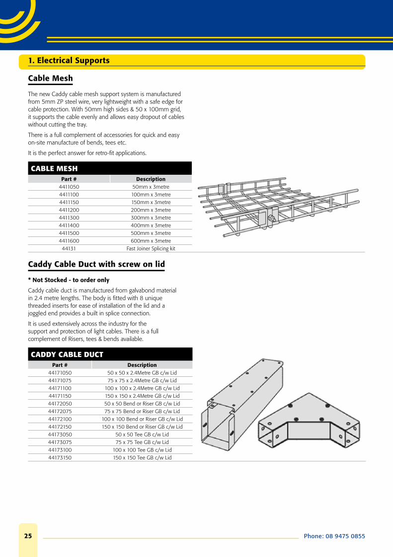
Cable Mesh
The new Caddy cable mesh support system is manufactured from 5mm ZP steel wire, very lightweight with a safe edge for cable protection. With 50mm high sides & 50 x 100mm grid, it supports the cable evenly and allows easy dropout of cables without cutting the tray.
There is a full complement of accessories for quick and easy on-site manufacture of bends, tees etc.
It is the perfect answer for retro-fi t applications.
CABLE MESHPart # Description
4411050 50mm x 3metre4411100 100mm x 3metre4411150 150mm x 3metre4411200 200mm x 3metre4411300 300mm x 3metre4411400 400mm x 3metre4411500 500mm x 3metre4411600 600mm x 3metre44131 Fast Joiner Splicing kit
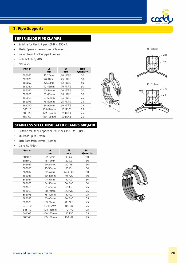
Caddy Cable Duct with screw on lid
* Not Stocked - to order only
Caddy cable duct is manufactured from galvabond material in 2.4 metre lengths. The body is fi tted with 8 unique threaded inserts for ease of installation of the lid and a joggled end provides a built in splice connection.
It is used extensively across the industry for the support and protection of light cables. There is a full complement of Risers, tees & bends available.
CADDY CABLE DUCTPart # Description
44171050 50 x 50 x 2.4Metre GB c/w Lid44171075 75 x 75 x 2.4Metre GB c/w Lid44171100 100 x 100 x 2.4Metre GB c/w Lid44171150 150 x 150 x 2.4Metre GB c/w Lid44172050 50 x 50 Bend or Riser GB c/w Lid44172075 75 x 75 Bend or Riser GB c/w Lid44172100 100 x 100 Bend or Riser GB c/w Lid44172150 150 x 150 Bend or Riser GB c/w Lid44173050 50 x 50 Tee GB c/w Lid44173075 75 x 75 Tee GB c/w Lid44173100 100 x 100 Tee GB c/w Lid44173150 150 x 150 Tee GB c/w Lid
1. Electrical Supports

www.caddyindustrial.com.au 26
Cover and Barrier Strip for Ladder-Tray and Ladder
COVER
We offer the full range of covers to suit all CT3/5 Ladder-tray and cable ladder.
Manufactured from galvabond material as standard and in 3 metre lengths.
It is available in fl at or peaked.
All covers for accessories are only available fl at and are made to order.
Covers are fi xed in position using cover clips or simply with a tek screw into the ladder rail.
Part # Description47CF155 155mm x 3 Metre Flat cover Galvabond47CF305 305mm x 3 Metre Flat cover Galvabond47CF455 455mm x 3 Metre Flat cover Galvabond47CF605 605mm x 3 Metre Flat cover Galvabond48LEE90 12B Cover Clips SS48LEG90 16A Cover Clips SS48LEK90 20B Cover Clips SS
Also available "to order" in HDG FINISH, STAINLESS STEEL or ALUMINIUM.
BARRIER STRIP
Barrier (divider) Strip to suit CT3/5 Ladder-tray and Cable Ladder.
Manufactured from Galvabond material as standard and in 3 metre lengths. Fixed in position with M6x20 pan screws and channel nuts through the pre punched slots in the base of the divider strip.
Part # Description48LEE55 CT3 & 12B Divider Strip x 3 Metre GB48LEM55 CT5, 16A & 20B Divider Strip x 3 Metre GB
Also available "to order" in HDG FINISH, STAINLESS STEEL or ALUMINIUM.
1. Electrical Supports

Phone: 08 9475 085527
INSULATED CLAMPS M8\M10
• Suitable for Steel, Copper or PVC Pipes 15NB to 150NB.
• Suits both M8/M10.
• ZP Finish.
Part # Amm
Ømm
Box Quantity
385013 12-15mm 15 Cu 50
385019 15-19mm 20 Cu 50
385021 20-24mm 20 NB 50
385025 25-30mm 25 Cu 50
385032 32-37mm 32/40 Cu 50
385043 40-45mm 40 PVC 50
385051 48-53mm 50 Cu 50
385055 54-58mm 50 PVC 50
385063 62-64mm 65 Cu 25
385069 68-73mm 65 PVC 25
385076 75-80mm 80 Cu 25
385082 82-86mm 80 PVC 25
385089 88-91mm 80 NB 25
385102 95-103mm 100 Cu 25
385110 108-116mm 110 PVC 25
385127 121-127mm 125 Cu 25
385140 133-141mm 125 NB 25
385152 147-153mm 150 Cu 25
385160 159-162mm 150 PVC 25
385165 165-168mm 150 NB 25
HINGED INSULATED PIPE CLAMPS
• Suitable for Copper or PVC Pipes 15NB to 100NB.
• Quick & Practical 1 screw lock in system.
• Suits both M8/M10.
• ZP Finish.
Part # Amm
Ømm
Box Quantity
389013 12-15mm 15 Cu 50
389019 15-19mm 20 Cu 50
389025 25-30mm 25 Cu 50
389032 32-37mm 32 Cu 50
389038 38-43mm 40 Cu 50
389043 40-45mm 40 PVC 50
389051 48-53mm 50 Cu 50
389055 54-58mm 50 PVC 50
389063 62-64mm 65 Cu 25
389069 68-73mm 65 PVC 25
389076 75-80mm 80 Cu 25
389082 82-86mm 80 PVC 25
389089 88-91mm 80 NB 25
389102 95-103mm 100 Cu 25
389110 108-116mm 110 PVC 25
2. Pipe Supports
www.caddyindustrial.com.au 28
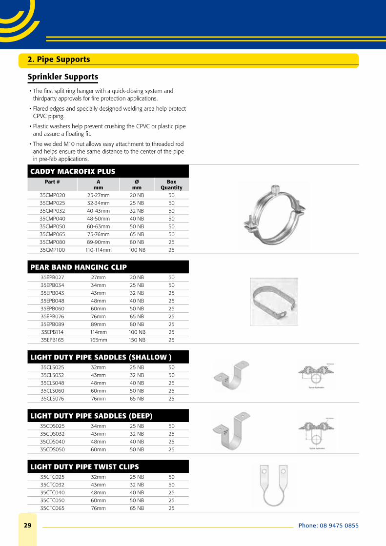
SUPER-SLIDE PIPE CLAMPS
• Suitable for Plastic Pipes 15NB to 150NB.
• Plastic Spacers prevent over tightening.
• Silicon lining to allow pipe to move.
• Suits both M8/M10.
• ZP Finish.
Part # Amm
Ømm
Box Quantity
386020 15-20mm 20 HDPE 50
386025 26-31mm 25 HDPE 50
386032 32-37mm 32 HDPE 50
386040 42-46mm 40 HDPE 50
386050 50-54mm 50 HDPE 50
386056 56-60mm 56 HDPE 50
386063 63-68mm 63 HDPE 25
386075 75-80mm 75 HDPE 25
386090 88-92mm 90 HDPE 25
386110 109-114mm 110 HDPE 25
386125 122-127mm 125 HDPE 25
386160 159-168mm 160 HDPE 25
STAINLESS STEEL INSULATED CLAMPS M8\M10
• Suitable for Steel, Copper or PVC Pipes 15NB to 150NB.
• M8 Boss up to 82mm.
• M10 Boss from 89mm-168mm.
• G316 SS Finish.
Part # Amm
Ømm
Box Quantity
383013 12-15mm 15 Cu 50
383019 15-19mm 20 Cu 50
383021 20-24mm 20 NB 50
383025 25-30mm 25 Cu 50
383032 32-37mm 32/40 Cu 50
383043 40-45mm 40 PVC 50
383051 48-51mm 50 Cu 50
383055 54-58mm 50 PVC 50
383063 59-63mm 65 Cu 25
383069 68-73mm 65 PVC 25
383076 75-80mm 80 Cu 25
383082 82-86mm 80 PVC 25
383089 89-91mm 80 NB 25
383102 95-103mm 100 Cu 25
383110 108-116mm 110 PVC 25
383160 159-162mm 150 PVC 25
383165 165-168mm 150 NB 25
2. Pipe Supports
Phone: 08 9475 085529
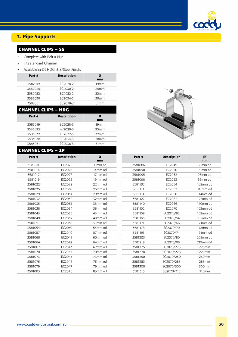
Sprinkler Supports
• The fi rst split ring hanger with a quick-closing system and thirdparty approvals for fi re protection applications.
• Flared edges and specially designed welding area help protect CPVC piping.
• Plastic washers help prevent crushing the CPVC or plastic pipe and assure a fl oating fi t.
• The welded M10 nut allows easy attachment to threaded rod and helps ensure the same distance to the center of the pipe in pre-fab applications.
CADDY MACROFIX PLUSPart # A
mmØ
mmBox
Quantity35CMP020 25-27mm 20 NB 50
35CMP025 32-34mm 25 NB 50
35CMP032 40-43mm 32 NB 50
35CMP040 48-50mm 40 NB 50
35CMP050 60-63mm 50 NB 50
35CMP065 75-76mm 65 NB 50
35CMP080 89-90mm 80 NB 25
35CMP100 110-114mm 100 NB 25
PEAR BAND HANGING CLIP35EPB027 27mm 20 NB 50
35EPB034 34mm 25 NB 50
35EPB043 43mm 32 NB 25
35EPB048 48mm 40 NB 25
35EPB060 60mm 50 NB 25
35EPB076 76mm 65 NB 25
35EPB089 89mm 80 NB 25
35EPB114 114mm 100 NB 25
35EPB165 165mm 150 NB 25
LIGHT DUTY PIPE SADDLES (SHALLOW )35CLS025 32mm 25 NB 50
35CLS032 43mm 32 NB 50
35CLS048 48mm 40 NB 25
35CLS060 60mm 50 NB 25
35CLS076 76mm 65 NB 25
LIGHT DUTY PIPE SADDLES (DEEP)35CDS025 34mm 25 NB 50
35CDS032 43mm 32 NB 25
35CDS040 48mm 40 NB 25
35CDS050 60mm 50 NB 25
LIGHT DUTY PIPE TWIST CLIPS35CTC025 32mm 25 NB 50
35CTC032 43mm 32 NB 50
35CTC040 48mm 40 NB 25
35CTC050 60mm 50 NB 25
35CTC065 76mm 65 NB 25
2. Pipe Supports
www.caddyindustrial.com.au 30
2. Pipe Supports
CHANNEL CLIPS – SS
• Complete with Bolt & Nut.
• Fits standard Channel.
• Available in ZP, HDG, & S/Steel Finish.
Part # Description Ømm
3582019 EC2028-2 19mm
3582025 EC2030-2 25mm
3582032 EC2032-2 32mm
3582038 EC2034-2 38mm
3582051 EC2038-2 51mm
CHANNEL CLIPS – HDGPart # Description Ø
mm3583019 EC2028-3 19mm
3583025 EC2030-3 25mm
3583032 EC2032-3 32mm
3583038 EC2034-3 38mm
3583051 EC2038-3 51mm
CHANNEL CLIPS – ZPPart # Description Ø
mmPart # Description Ø
mm3581011 EC2025 11mm od 3581086 EC2049 86mm od
3581014 EC2026 14mm od 3581090 EC2050 90mm od
3581017 EC2027 17mm od 3581095 EC2052 95mm od
3581019 EC2028 19mm od 3581098 EC2053 98mm od
3581022 EC2029 22mm od 3581102 EC2054 102mm od
3581025 EC2030 25mm od 3581111 EC2057 111mm od
3581029 EC2031 29mm od 3581114 EC2058 114mm od
3581032 EC2032 32mm od 3581127 EC2062 127mm od
3581035 EC2033 35mm od 3581140 EC2066 140mm od
3581038 EC2034 38mm od 3581152 EC2070 152mm od
3581043 EC2035 43mm od 3581159 EC2070/62 159mm od
3581049 EC2037 49mm od 3581165 EC2070/64 165mm od
3581051 EC2038 51mm od 3581171 EC2070/66 171mm od
3581054 EC2039 54mm od 3581178 EC2070/70 178mm od
3581057 EC2040 57mm od 3581191 EC2070/74 191mm od
3581060 EC2041 60mm od 3581203 EC2070/80 203mm od
3581064 EC2042 64mm od 3581219 EC2070/86 219mm od
3581067 EC2043 67mm od 3581225 EC2070/225 225mm
3581070 EC2044 70mm od 3581228 EC2070/228 228mm
3581073 EC2045 73mm od 3581250 EC2070/250 250mm
3581076 EC2046 76mm od 3581283 EC2070/283 283mm
3581079 EC2047 79mm od 3581300 EC2070/300 300mm
3581083 EC2048 83mm od 3581315 EC2070/315 315mm
Phone: 08 9475 085531
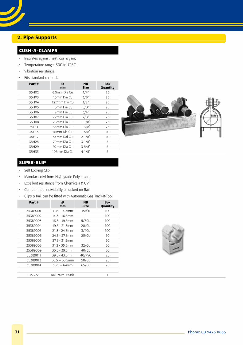
CUSH-A-CLAMPS
• Insulates against heat loss & gain.
• Temperature range -30C to 125C.
• Vibration resistance.
• Fits standard channel.
Part # Ømm
NB Size
Box Quantity
35H02 6.5mm Dia Cu 1/4" 25
35H03 10mm Dia Cu 3/8” 25
35H04 12.7mm Dia Cu 1/2" 25
35H05 16mm Dia Cu 5/8” 25
35H06 19mm Dia Cu 3/4” 25
35H07 22mm Dia Cu 7/8” 25
35H08 28mm Dia Cu 1 1/8” 25
35H11 35mm Dia Cu 1 3/8” 25
35H13 41mm Dia Cu 1 5/8” 10
35H17 54mm Dai Cu 2 1/8” 10
35H25 79mm Dia Cu 3 1/8” 5
35H29 92mm Dia Cu 3 5/8” 5
35H33 105mm Dia Cu 4 1/8” 5
SUPER-KLIP
• Self Locking Clip.
• Manufactured from High grade Polyamide.
• Excellent resistance from Chemicals & UV.
• Can be fi tted individually or racked on Rail.
• Clips & Rail can be fi tted with Automatic Gas Track-It-Tool.
Part # Ømm
NB Size
Box Quantity
35389001 11.8 - 14.3mm 15/Cu 100
35389002 14.3 - 16.8mm 100
35389003 16.8 - 19.5mm 5/8Cu 100
35389004 19.5 - 21.8mm 20/Cu 100
35389005 21.8 - 24.8mm 3/4Cu 100
35389006 24.8 - 27.8mm 25/Cu 50
35389007 27.8 - 31.2mm 50
35389008 31.2 - 35.5mm 32/Cu 50
35389009 35.5 - 39.5mm 40/Cu 50
35389011 39.5 - 43.5mm 40/PVC 25
35389013 50.5 – 55.5mm 50/Cu 25
35389014 58.5 – 64mm 65/Cu 25
353R2 Rail 2Mtr Length 1
2. Pipe Supports
www.caddyindustrial.com.au 32
2. Pipe Supports
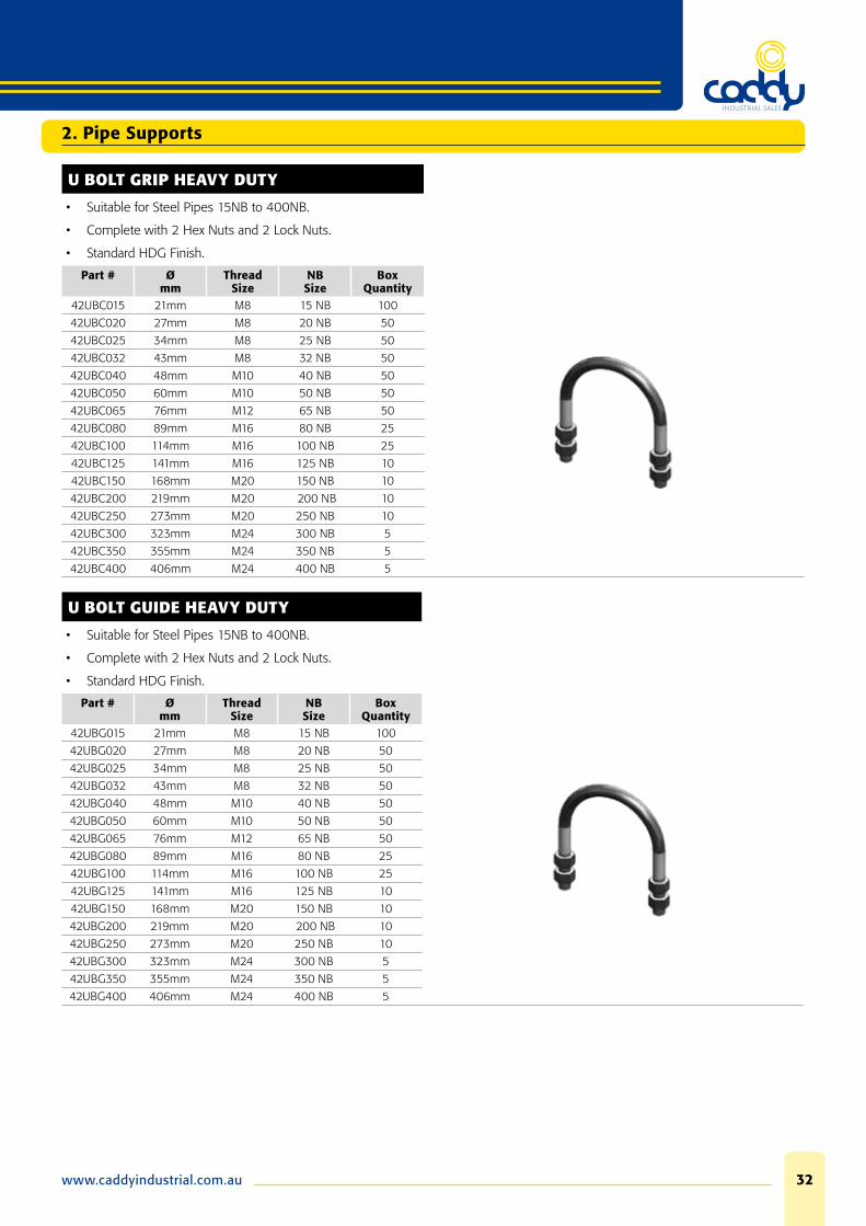
U BOLT GRIP HEAVY DUTY
• Suitable for Steel Pipes 15NB to 400NB.
• Complete with 2 Hex Nuts and 2 Lock Nuts.
• Standard HDG Finish.
Part # Ømm
Thread Size
NBSize
Box Quantity
42UBC015 21mm M8 15 NB 100
42UBC020 27mm M8 20 NB 50
42UBC025 34mm M8 25 NB 50
42UBC032 43mm M8 32 NB 50
42UBC040 48mm M10 40 NB 50
42UBC050 60mm M10 50 NB 50
42UBC065 76mm M12 65 NB 50
42UBC080 89mm M16 80 NB 25
42UBC100 114mm M16 100 NB 25
42UBC125 141mm M16 125 NB 10
42UBC150 168mm M20 150 NB 10
42UBC200 219mm M20 200 NB 10
42UBC250 273mm M20 250 NB 10
42UBC300 323mm M24 300 NB 5
42UBC350 355mm M24 350 NB 5
42UBC400 406mm M24 400 NB 5
U BOLT GUIDE HEAVY DUTY
• Suitable for Steel Pipes 15NB to 400NB.
• Complete with 2 Hex Nuts and 2 Lock Nuts.
• Standard HDG Finish.
Part # Ømm
Thread Size
NBSize
Box Quantity
42UBG015 21mm M8 15 NB 100
42UBG020 27mm M8 20 NB 50
42UBG025 34mm M8 25 NB 50
42UBG032 43mm M8 32 NB 50
42UBG040 48mm M10 40 NB 50
42UBG050 60mm M10 50 NB 50
42UBG065 76mm M12 65 NB 50
42UBG080 89mm M16 80 NB 25
42UBG100 114mm M16 100 NB 25
42UBG125 141mm M16 125 NB 10
42UBG150 168mm M20 150 NB 10
42UBG200 219mm M20 200 NB 10
42UBG250 273mm M20 250 NB 10
42UBG300 323mm M24 300 NB 5
42UBG350 355mm M24 350 NB 5
42UBG400 406mm M24 400 NB 5

Phone: 08 9475 085533
STANDARD U BOLT LIGHT DUTY
• Suitable for Steel Pipes 15NB to 250NB.
• Complete with 2 Hex Nuts.
• Standard HDG Finish.
Part # Ømm
Thread Size
NBSize
Box Quantity
42U020 27mm M10 20 NB 50
42U025 34mm M10 25 NB 50
42U032 43mm M10 32 NB 50
42U040 48mm M10 40 NB 50
42U050 60mm M10 50 NB 50
42U065 76mm M12 65 NB 50
42U080 89mm M12 80 NB 25
42U100 114mm M12 100 NB 25
42U125 141mm M12 125 NB 10
42U150 168mm M12 150 NB 10
42U200 219mm M16 200 NB 10
42U250 273mm M20 250 NB 10
MEDIUM DUTY 2 BOLT CLAMPS
• Standard Finish HDG.
• Complete with Bolt & Nut.
• 40mm x 5mm Material.
Part # Description Ømm
NBSize
Box Quantity
35163060 ER16-060 60mm 50 NB 25
35163076 ER16-076 76mm 65 NB 10
35163089 ER16-089 89mm 80 NB 10
35163102 ER16-102 102mm 100 Cu 10
35163114 ER16-114 114mm 100 NB 10
35163127 ER16-127 127mm 125 Cu 10
35163140 ER16-140 140mm 125 NB 10
35163152 ER16-152 152mm 150 Cu 5
35163165 ER16-165 165mm 150 NB 5
35163203 ER16-203 203mm 200 Cu 5
35163219 ER16-219 219mm 200 NB 5
35163250 ER16-250 250mm 225 PVC 5
35163273 ER16-273 273mm 250 NB 5
35163303 ER16-303 303mm 300 Cu 5
35163315 ER16-315 315mm 300 PVC 5
35163400 ER16-400 400mm 375 PVC 5
2. Pipe Supports
www.caddyindustrial.com.au 34
2. Pipe Supports
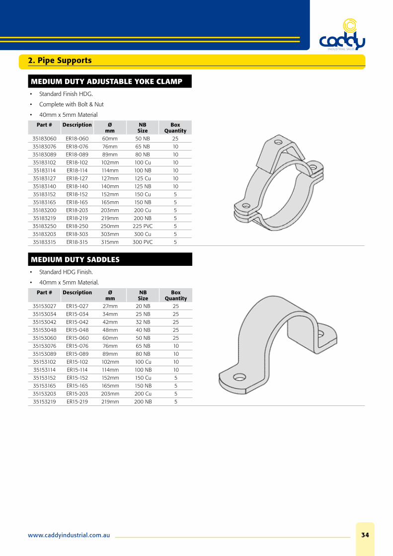
MEDIUM DUTY ADJUSTABLE YOKE CLAMP
• Standard Finish HDG.
• Complete with Bolt & Nut
• 40mm x 5mm Material
Part # Description Ømm
NB Size
Box Quantity
35183060 ER18-060 60mm 50 NB 25
35183076 ER18-076 76mm 65 NB 10
35183089 ER18-089 89mm 80 NB 10
35183102 ER18-102 102mm 100 Cu 10
35183114 ER18-114 114mm 100 NB 10
35183127 ER18-127 127mm 125 Cu 10
35183140 ER18-140 140mm 125 NB 10
35183152 ER18-152 152mm 150 Cu 5
35183165 ER18-165 165mm 150 NB 5
35183200 ER18-203 203mm 200 Cu 5
35183219 ER18-219 219mm 200 NB 5
35183250 ER18-250 250mm 225 PVC 5
35183203 ER18-303 303mm 300 Cu 5
35183315 ER18-315 315mm 300 PVC 5
MEDIUM DUTY SADDLES
• Standard HDG Finish.
• 40mm x 5mm Material.
Part # Description Ømm
NB Size
Box Quantity
35153027 ER15-027 27mm 20 NB 25
35153034 ER15-034 34mm 25 NB 25
35153042 ER15-042 42mm 32 NB 25
35153048 ER15-048 48mm 40 NB 25
35153060 ER15-060 60mm 50 NB 25
35153076 ER15-076 76mm 65 NB 10
35153089 ER15-089 89mm 80 NB 10
35153102 ER15-102 102mm 100 Cu 10
35153114 ER15-114 114mm 100 NB 10
35153152 ER15-152 152mm 150 Cu 5
35153165 ER15-165 165mm 150 NB 5
35153203 ER15-203 203mm 200 Cu 5
35153219 ER15-219 219mm 200 NB 5
Phone: 08 9475 085535
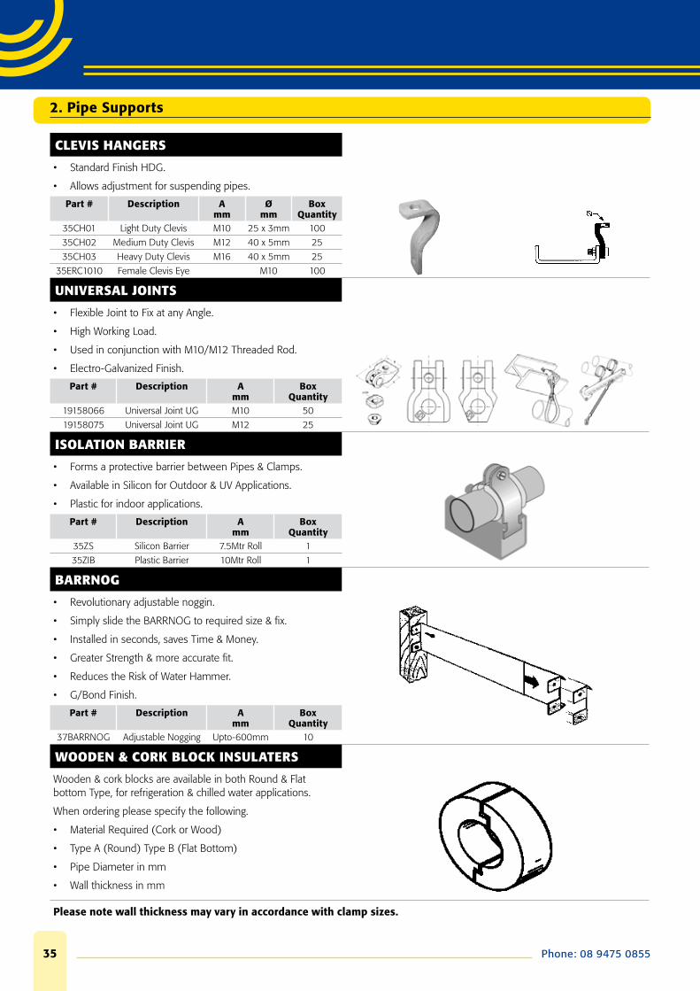
CLEVIS HANGERS
• Standard Finish HDG.
• Allows adjustment for suspending pipes.
Part # Description Amm
Ømm
Box Quantity
35CH01 Light Duty Clevis M10 25 x 3mm 100
35CH02 Medium Duty Clevis M12 40 x 5mm 25
35CH03 Heavy Duty Clevis M16 40 x 5mm 25
35ERC1010 Female Clevis Eye M10 100
UNIVERSAL JOINTS
• Flexible Joint to Fix at any Angle.
• High Working Load.
• Used in conjunction with M10/M12 Threaded Rod.
• Electro-Galvanized Finish.
Part # Description Amm
Box Quantity
19158066 Universal Joint UG M10 50
19158075 Universal Joint UG M12 25
ISOLATION BARRIER
• Forms a protective barrier between Pipes & Clamps.
• Available in Silicon for Outdoor & UV Applications.
• Plastic for indoor applications.
Part # Description Amm
Box Quantity
35ZS Silicon Barrier 7.5Mtr Roll 1
35ZIB Plastic Barrier 10Mtr Roll 1
BARRNOG
• Revolutionary adjustable noggin.
• Simply slide the BARRNOG to required size & fi x.
• Installed in seconds, saves Time & Money.
• Greater Strength & more accurate fi t.
• Reduces the Risk of Water Hammer.
• G/Bond Finish.
Part # Description Amm
Box Quantity
37BARRNOG Adjustable Nogging Upto-600mm 10
WOODEN & CORK BLOCK INSULATERS
Wooden & cork blocks are available in both Round & Flat bottom Type, for refrigeration & chilled water applications.
When ordering please specify the following.
• Material Required (Cork or Wood)
• Type A (Round) Type B (Flat Bottom)
• Pipe Diameter in mm
• Wall thickness in mm
Please note wall thickness may vary in accordance with clamp sizes.
2. Pipe Supports
www.caddyindustrial.com.au 36
2. Pipe Supports
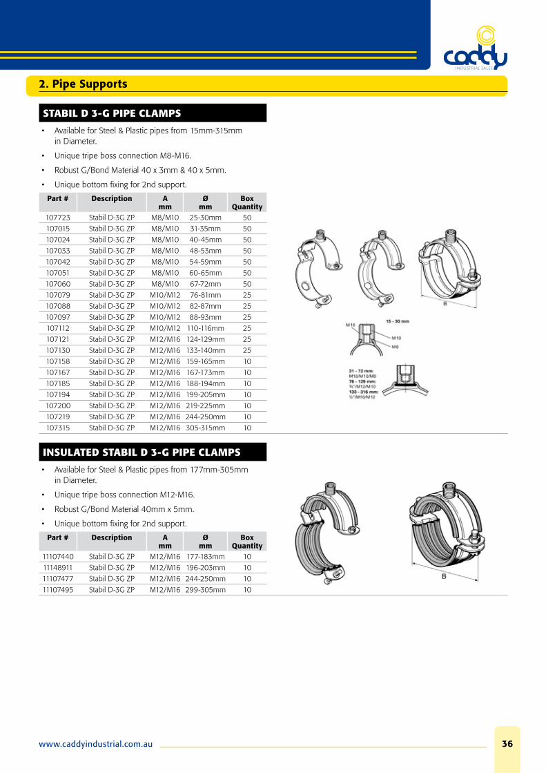
STABIL D 3-G PIPE CLAMPS
• Available for Steel & Plastic pipes from 15mm-315mm in Diameter.
• Unique tripe boss connection M8-M16.
• Robust G/Bond Material 40 x 3mm & 40 x 5mm.
• Unique bottom fi xing for 2nd support.
Part # Description Amm
Ømm
Box Quantity
107723 Stabil D-3G ZP M8/M10 25-30mm 50
107015 Stabil D-3G ZP M8/M10 31-35mm 50
107024 Stabil D-3G ZP M8/M10 40-45mm 50
107033 Stabil D-3G ZP M8/M10 48-53mm 50
107042 Stabil D-3G ZP M8/M10 54-59mm 50
107051 Stabil D-3G ZP M8/M10 60-65mm 50
107060 Stabil D-3G ZP M8/M10 67-72mm 50
107079 Stabil D-3G ZP M10/M12 76-81mm 25
107088 Stabil D-3G ZP M10/M12 82-87mm 25
107097 Stabil D-3G ZP M10/M12 88-93mm 25
107112 Stabil D-3G ZP M10/M12 110-116mm 25
107121 Stabil D-3G ZP M12/M16 124-129mm 25
107130 Stabil D-3G ZP M12/M16 133-140mm 25
107158 Stabil D-3G ZP M12/M16 159-165mm 10
107167 Stabil D-3G ZP M12/M16 167-173mm 10
107185 Stabil D-3G ZP M12/M16 188-194mm 10
107194 Stabil D-3G ZP M12/M16 199-205mm 10
107200 Stabil D-3G ZP M12/M16 219-225mm 10
107219 Stabil D-3G ZP M12/M16 244-250mm 10
107315 Stabil D-3G ZP M12/M16 305-315mm 10
INSULATED STABIL D 3-G PIPE CLAMPS
• Available for Steel & Plastic pipes from 177mm-305mm in Diameter.
• Unique tripe boss connection M12-M16.
• Robust G/Bond Material 40mm x 5mm.
• Unique bottom fi xing for 2nd support.
Part # Description Amm
Ømm
Box Quantity
11107440 Stabil D-3G ZP M12/M16 177-183mm 10
11148911 Stabil D-3G ZP M12/M16 196-203mm 10
11107477 Stabil D-3G ZP M12/M16 244-250mm 10
11107495 Stabil D-3G ZP M12/M16 299-305mm 10
Phone: 08 9475 085537
STABIL ACCESSORIES
• Connectors which allow pipes to be supported from each other.
• Simply insert nut or screw into clamp & pipe will secure fi tting.
• Quickly attach any size Stabil Clamp with triple thread connector.
• Standard ZP Finish.
Part # Description Ømm
Box Quantity
19114097 Countersunk Screw Connector M8 x 40 100
19143626 Triple Thread Connecting Nut M8/M10/M16 50
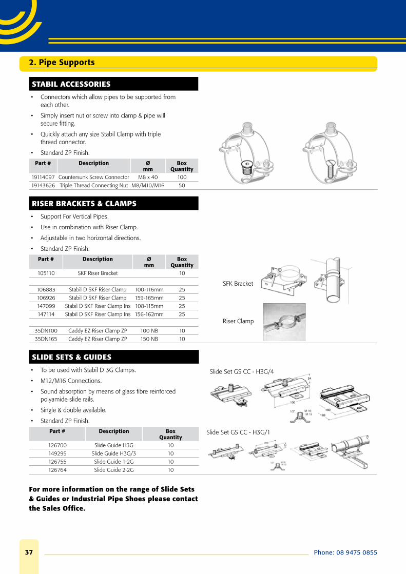
RISER BRACKETS & CLAMPS
• Support For Vertical Pipes.
• Use in combination with Riser Clamp.
• Adjustable in two horizontal directions.
• Standard ZP Finish.
Part # Description Ømm
Box Quantity
SFK Bracket
Riser Clamp
105110 SKF Riser Bracket 10
106883 Stabil D SKF Riser Clamp 100-116mm 25
106926 Stabil D SKF Riser Clamp 159-165mm 25
147099 Stabil D SKF Riser Clamp Ins 108-115mm 25
147114 Stabil D SKF Riser Clamp Ins 156-162mm 25
35DN100 Caddy EZ Riser Clamp ZP 100 NB 10
35DN165 Caddy EZ Riser Clamp ZP 150 NB 10
SLIDE SETS & GUIDES
• To be used with Stabil D 3G Clamps.
• M12/M16 Connections.
• Sound absorption by means of glass fi bre reinforced polyamide slide rails.
• Single & double available.
• Standard ZP Finish.
Slide Set GS CC - H3G/4
Part # Description Box Quantity
Slide Set GS CC - H3G/1
126700 Slide Guide H3G 10
149295 Slide Guide H3G/3 10
126755 Slide Guide 1-2G 10
126764 Slide Guide 2-2G 10
For more information on the range of Slide Sets & Guides or Industrial Pipe Shoes please contact the Sales Offi ce.
2. Pipe Supports

www.caddyindustrial.com.au 38
3. Sikla Support Systems
Pressix CC 27 - Channel System
PRESSIX 27 SUPPORT SYSTEM RANGE
A lightweight support system for the Electrical, Mechanical & Plumbing Industries.
The fastest installed system on the market, Simply Press, Fix, Finished.
The most straightforward range for all applications, 8 products in the Range.
The channel has rolled edges and fl anks to generate a high level of stiffness and resistance against torsion forces, slotted base receives M8 & M10 fi xings without the need to drill.
All accessories are pre-assembled no loose bolts & nuts to misplace.
Accessories lock automatically simply press the bolt head for speed of installation by up to 50%.
Part # Amm
Ømm
Box Quantity
198025 27 x 27 x 3Mtr Channel Pre Galvanized Finish 10
193976 ADK 27 End Cap HD-PE Yellow 100
19106500 M10 x 25 T Head Bolt Electro-Galvanized 100
19114422 M10 Holding Bracket Electro-Galvanized 100
19181577 M10 Channel Nut Electro-Galvanized 100
195956 M6 Speed Nut Electro-Galvanized 100
195949 M8 Speed Nut Electro-Galvanized 100
195888 M8 x 35 Block Set Electro-Galvanized 100
195895 M8 x 75 Block Set Electro-Galvanized 100
195932 M8 Block Electro-Galvanized 100
193938 Cantilever Bkt 200mm Electro-Galvanized 10
193952 Cantilever Bkt 300mm Electro-Galvanized 10
195772 Angle Connecter Electro-Galvanized 50
195789 Wall Angle Connecter Electro-Galvanized 50
195871 Fitting Set Electro-Galvanized 10
195864 Beam Clamp Electro-Galvanized 20
19107769 Webbing Piece Electro-Galvanized 10

Phone: 08 9475 085539
Pressix CC 27 - Channel System
END CAP ADK 27
ApplicationTo be used for safely and neatly covering the ends of Sikla Channels 27.
Technical DataMaterial: HD-PE Yellow.
Part # Type Wkg
Box Quantity
193969 27/15 0.01 100
193976 27/27 0.01 100
HOLDING BRACKET HK 27
ApplicationSafety element for Sikla channels to be used instead of simple washers. The Holding Bracket prevents the edges along the opening of the channels from bending, and ensures optimum load distribution. When loads are imposed along the channels, B 27 Holding Brackets provide additional safety due to embossed teeth, which bite into the channel.
Suitable for channels type 27.
Technical DataMaterial: Malleable iron, electro-galvanised.
Part # Type Boremm
Wkg
Box Quantity
19114422 27/10 M11 0.02 50
T-HEAD BOLT 27
ApplicationSuitable for Sikla Channels of type 27.
Confi gurationPre-assembled with washer and nut.
> When using a Holding Bracket for type HM 27 M10, the washer is not needed.
Technical DataMaterial: Steel, cold-forged, electro-galvanised.
Part # Type Thread Connection Lengthmm
Wkg
Box Quantity
19106500 Hm 27 M10 x 25/14 M10 25 0.04 50
3. Sikla Support Systems

www.caddyindustrial.com.au 40
3. Sikla Support Systems
Pressix CC 27 - Channel System
CHANNEL NUT NT 27
ApplicationChannel Nuts type 27 are suitable for channels of 27 mm width.
Technical DataMaterial: Malleable cast iron, electro-galvanised.
Part # Type Load Capacity (tension)kN
Wkg
Box Quantity
19174188 27-M6 1.7 0.01 100
19124382 27-M8 1.7 0.01 100
19181577 27-M10 1.7 0.01 100
SPEED NUT NT CC 27
ApplicationIn particular useful for installation in vertical channels or in places of diffi cult access.
Further advantages:• For all Sikla channels 27/27 and 27/15, independent of the
channel's height.
• No getting stuck on bolt heads when sliding in the channel.
• No appearance of settlement after tightening.
Confi gurationChannel Nut and Spring are tightly connected.
InstallationAfter inserting the Speed Nut into the channel opening, exert a slight axial pressure. This will cause the nut to turn to the right and engage into the channel. De-installation simply requires the nut to be turned to the left and pulled free. Installation and de-installation do not require tools and may be repeated several times.
Tighten the part to be connected - that's it!
Technical DataFz= 1.5 kN
Material: Channel nut: Steel, class 5.6, electro-galvanised
Spring washer: Sheet metal spring steel, rustproof
Part # Type Wkg
Box Quantity
195956 CC 27-M6 0.01 100
195949 CC 27-M8 0.01 100
Phone: 08 9475 085541
Pressix CC 27 - Channel System
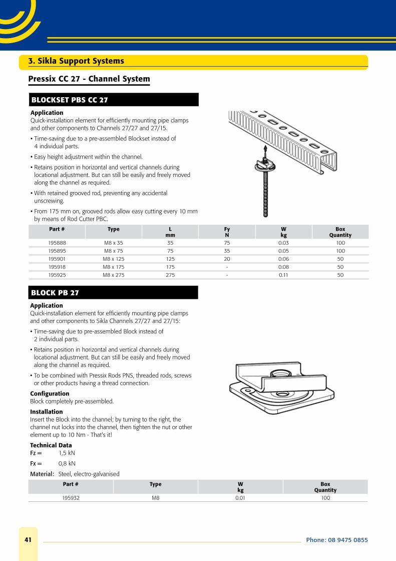
BLOCKSET PBS CC 27
ApplicationQuick-installation element for effi ciently mounting pipe clamps and other components to Channels 27/27 and 27/15.
• Time-saving due to a pre-assembled Blockset instead of 4 individual parts.
• Easy height adjustment within the channel.
• Retains position in horizontal and vertical channels during locational adjustment. But can still be easily and freely moved along the channel as required.
• With retained grooved rod, preventing any accidental unscrewing.
• From 175 mm on, grooved rods allow easy cutting every 10 mm by means of Rod Cutter PBC.
Part # Type Lmm
FyN
Wkg
Box Quantity
195888 M8 x 35 35 75 0.03 100
195895 M8 x 75 75 35 0.05 100
195901 M8 x 125 125 20 0.06 50
195918 M8 x 175 175 - 0.08 50
195925 M8 x 275 275 - 0.11 50
BLOCK PB 27
ApplicationQuick-installation element for effi ciently mounting pipe clamps and other components to Sikla Channels 27/27 and 27/15:
• Time-saving due to pre-assembled Block instead of 2 individual parts.
• Retains position in horizontal and vertical channels during locational adjustment. But can still be easily and freely moved along the channel as required.
• To be combined with Pressix Rods PNS, threaded rods, screws or other products having a thread connection.
Confi gurationBlock completely pre-assembled.
InstallationInsert the Block into the channel; by turning to the right, the channel nut locks into the channel, then tighten the nut or other element up to 10 Nm - That's it!
Technical DataFz = 1,5 kN
Fx = 0,8 kN
Material: Steel, electro-galvanised
Part # Type Wkg
Box Quantity
195932 M8 0.01 100
3. Sikla Support Systems
www.caddyindustrial.com.au 42
3. Sikla Support Systems
Pressix CC 27 - Channel System
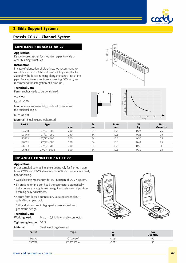
CANTILEVER BRACKET AK 27
ApplicationReady-to-use bracket for mounting pipes to walls or other building structures.
InstallationIn case of elongation of pipe lines, we recommend to use slide elements. A tie rod is absolutely essential for absorbing the forces running along the centre line of the pipe. For cantilever structures exceeding 500 mm, we recommend the integration of a prop-up.
Technical DataPerm. anchor loads to be considered.
act. adm.
fadm. L/150
Max. torsional moment Mtmax without considering the torsional angle.
M = 20 Nm
Material: Steel, electro-galvanised
Part # Type Lmm
bmm
Boremm
Wkg
Box Quantity
193938 27/27 - 200 200 64 10.5 0.23 25
193945 27/27 - 250 250 64 10.5 0.26 25
193952 27/27 - 300 300 64 10.5 0.30 25
196021 27/27 - 500 500 64 10.5 0.44 25
196038 27/27 - 700 700 64 10.5 0.58 1
196755 27/27 - 300q 300 64 10.5 0.30 25
90° ANGLE CONNECTOR NT CC 27
ApplicationPre-assembled connecting angle exclusively for frames made from 27/15 and 27/27 channels. Type W for connection to wall, fl oor or ceiling.
• Quick-locking mechanism for 90° junction of CC-27 system.
• By pressing on the bolt head the connector automatically locks on, supporting its own weight and retaining its position, enabling easy adjustment.
• Secure form-locked connection. Serrated channel nut with M8 clamping bolt.
Stiff and strong due to high-performance steel and geometric design.
Technical DataWorking load: Fxshear = 0,8 kN per angle connector
Tightening torque: 10 Nm
Material: Steel, electro-galvanised
Part # Type Wkg
Box Quantity
195772 CC 27-90° 0.09 50
195789 CC 27-90° W 0.07 50
Phone: 08 9475 085543
Pressix CC 27 - Channel System
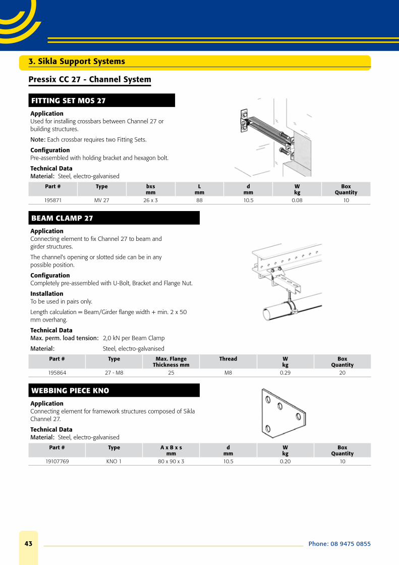
FITTING SET MOS 27
ApplicationUsed for installing crossbars between Channel 27 or building structures.
Note: Each crossbar requires two Fitting Sets.
Confi gurationPre-assembled with holding bracket and hexagon bolt.
Technical DataMaterial: Steel, electro-galvanised
Part # Type bxsmm
Lmm
dmm
Wkg
Box Quantity
195871 MV 27 26 x 3 88 10.5 0.08 10
BEAM CLAMP 27
ApplicationConnecting element to fi x Channel 27 to beam and girder structures.
The channel's opening or slotted side can be in any possible position.
Confi gurationCompletely pre-assembled with U-Bolt, Bracket and Flange Nut.
InstallationTo be used in pairs only.
Length calculation = Beam/Girder fl ange width + min. 2 x 50 mm overhang.
Technical DataMax. perm. load tension: 2,0 kN per Beam Clamp
Material: Steel, electro-galvanised
Part # Type Max. Flange Thickness mm
Thread Wkg
Box Quantity
195864 27 - M8 25 M8 0.29 20
WEBBING PIECE KNO
ApplicationConnecting element for framework structures composed of Sikla Channel 27.
Technical DataMaterial: Steel, electro-galvanised
Part # Type A x B x smm
dmm
Wkg
Box Quantity
19107769 KNO 1 80 x 90 x 3 10.5 0.20 10
3. Sikla Support Systems
www.caddyindustrial.com.au 44
3. Sikla Support Systems
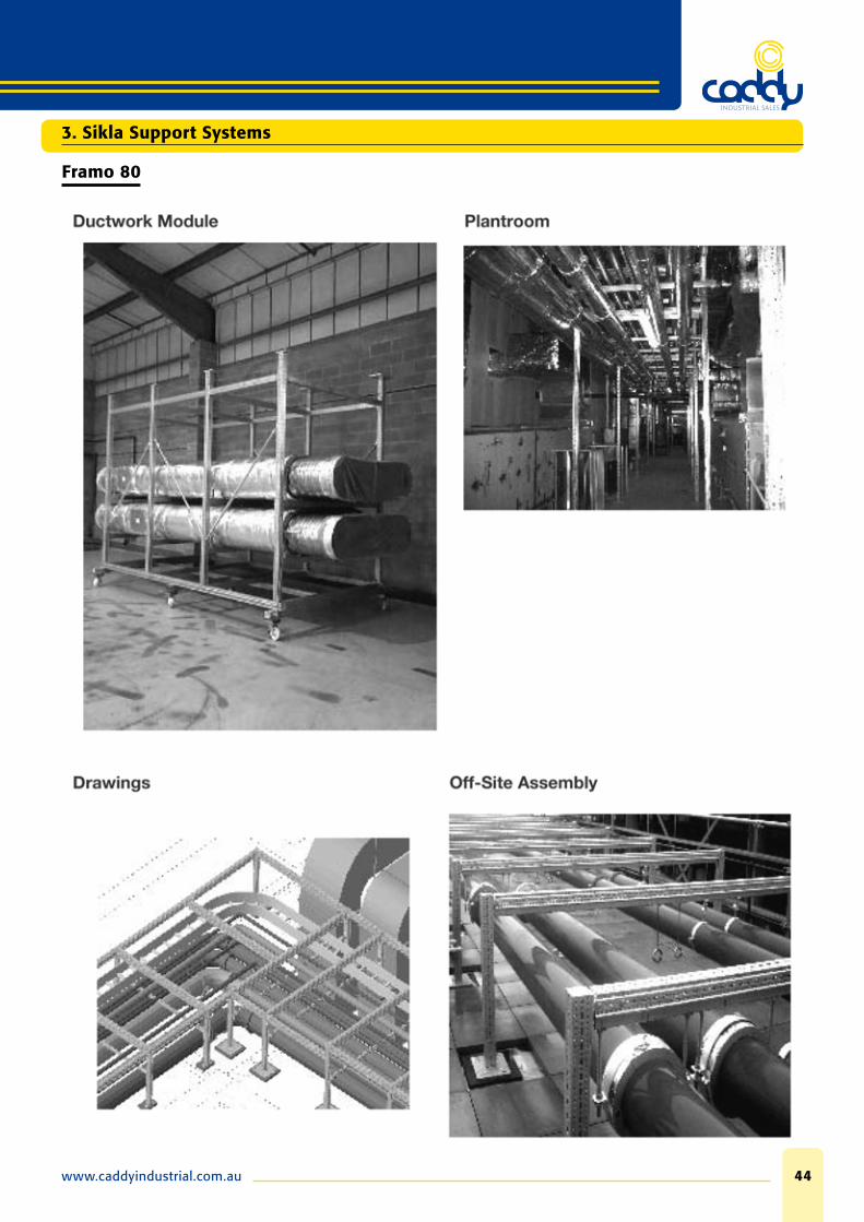
Framo 80

Phone: 08 9475 085545
3. Sikla Support Systems
Framo 80
FRAMO 80 BEAM SECTION
A Multi-function beam profi le for horizontal, vertical and 3-D support structures in a wide variety of building and industrial applications.
In addition to the high torsional resistance achieved using a totally closed profi le, structural elements and pipe supports can be attached on all 4 sides with virtually no placement restrictions. Specifi cally designed fi xing holes combined with special FLS self-tapping screws ensure precise component placement and secure form-locked fi xings.
Part # Amm
Ømm
Box Quantity
192539 TP-F80 Framo 80 x 6Mtr HDG 1
192764 AK-F-80 Cantilever 400mm HDG 1
192771 AK-F-80 Cantilever 800mm HDG 1
192788 TKO-F-80 Beam Brkt 400mm HDG 1
192795 TKO-F-80 Beam Brkt 800mm HDG 1
192856 STA-F-80 End Support HDG 1
192863 STA-F-80-E End Support HDG 1
192801 WBD-F-80 80/120 End Support HDG 1
192825 WBD-F-80 161/200 End Support HDG 1
192887 SA-F-80-41 Channel Adapter HDG 1
192512 FLS-F-80 Self Forming Screws HDG 100
192683 SB-F-80-16 U Holder HDG 20
194010 SB-F-80-40 U Holder HDG 10
192674 ADK-F-80 End Cap PP/Yellow 25
www.caddyindustrial.com.au 46
Framo 80
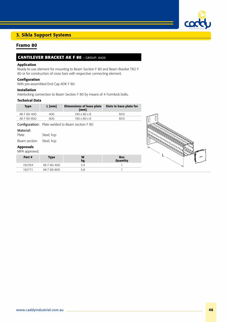
CANTILEVER BRACKET AK F 80 – GROUP: A420
ApplicationReady-to-use element for mounting to Beam Section F 80 and Beam Bracket TKO F 80 or for construction of cross bars with respective connecting element.
Confi gurationWith pre-assembled End Cap ADK F 80.
InstallationInterlocking connection to Beam Section F 80 by means of 4 Formlock bolts.
Technical Data
Type L [mm] Dimensions of base plate [mm]
Slots in base plate for
AK F 80-400 400 190 x 80 x 8 M10AK F 80-800 800 190 x 80 x 8 M10
Confi guration: Plate welded to Beam section F 80
Material:Plate Steel, hcp
Beam section Steel, hcp
ApprovalsMPA approved.
Part # Type Wkg
Box Quantity
192764 AK F 80-400 3.4 1
192771 AK F 80-800 5.8 1
3. Sikla Support Systems

Phone: 08 9475 085547
3. Sikla Support Systems
Framo 80
BEAM BRACKET TKO F 80 – GROUP: A423
ApplicationReady-to-use element for mounting to walls, fl oors, and ceilings as well as to Simotec Systems 100 and 120 or for assembling crossbars with the respective connecting element.
Confi gurationWith pre-assembled End Cap ADK F 80.
InstallationDepending on the situation, different options are recommended:
a) Fixing to building structure using 4 heavy duty anchors M12.
b) Frictional connection to steel beams (fl ange width 80 - 120 mm) with Assembly Set P2.
c) Interlocking connection to beams of System 100 or 120 by means of Bracket Plates FV 100/120.
Technical Data
Type L [mm] Dimensions of base plate [mm]
Slots in base plate for
TKO F80-400 400 220 x 220 x 12 M12TKO F80-800 800 220 x 220 x 12 M12
Confi guration: Plate welded to Beam section F 80
Material:Plate Steel, hcp
Beam section Steel, hcp
ApprovalsMPA approved.
Part # Type Wkg
Box Quantity
192788 TKO F 80-400 6.6 1
192795 TKO F 80-800 9.2 1
www.caddyindustrial.com.au 48
Framo 80
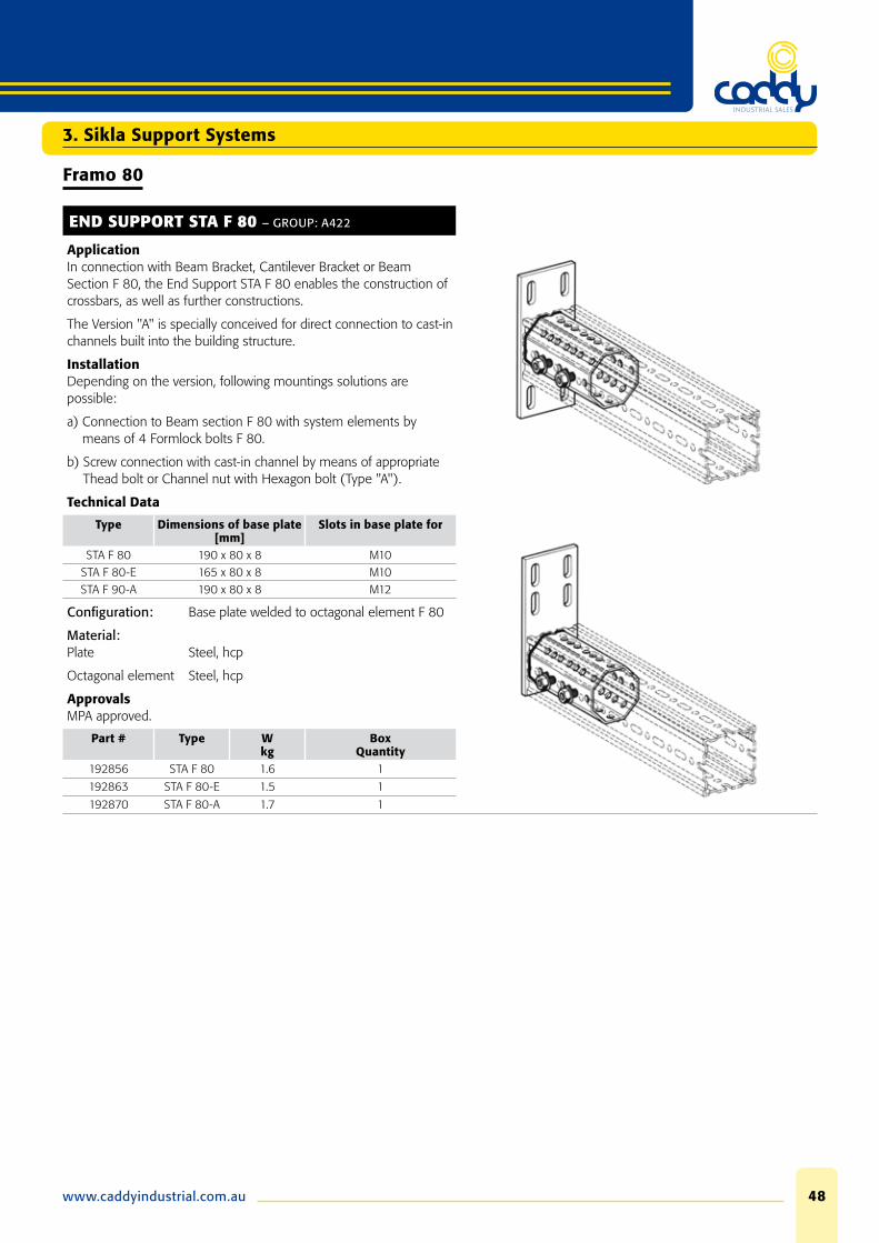
END SUPPORT STA F 80 – GROUP: A422
ApplicationIn connection with Beam Bracket, Cantilever Bracket or Beam Section F 80, the End Support STA F 80 enables the construction of crossbars, as well as further constructions.
The Version "A" is specially conceived for direct connection to cast-in channels built into the building structure.
InstallationDepending on the version, following mountings solutions are possible:
a) Connection to Beam section F 80 with system elements by means of 4 Formlock bolts F 80.
b) Screw connection with cast-in channel by means of appropriate Thead bolt or Channel nut with Hexagon bolt (Type "A").
Technical Data
Type Dimensions of base plate [mm]
Slots in base plate for
STA F 80 190 x 80 x 8 M10STA F 80-E 165 x 80 x 8 M10STA F 90-A 190 x 80 x 8 M12
Confi guration: Base plate welded to octagonal element F 80
Material:Plate Steel, hcp
Octagonal element Steel, hcp
ApprovalsMPA approved.
Part # Type Wkg
Box Quantity
192856 STA F 80 1.6 1
192863 STA F 80-E 1.5 1
192870 STA F 80-A 1.7 1
3. Sikla Support Systems
Phone: 08 9475 085549
3. Sikla Support Systems
Framo 80
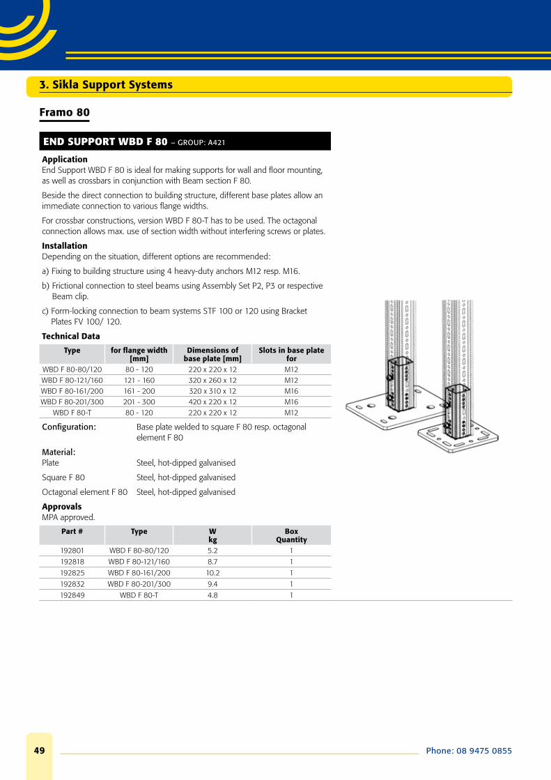
END SUPPORT WBD F 80 – GROUP: A421
ApplicationEnd Support WBD F 80 is ideal for making supports for wall and fl oor mounting, as well as crossbars in conjunction with Beam section F 80.
Beside the direct connection to building structure, different base plates allow an immediate connection to various fl ange widths.
For crossbar constructions, version WBD F 80-T has to be used. The octagonal connection allows max. use of section width without interfering screws or plates.
InstallationDepending on the situation, different options are recommended:
a) Fixing to building structure using 4 heavy-duty anchors M12 resp. M16.
b) Frictional connection to steel beams using Assembly Set P2, P3 or respective Beam clip.
c) Form-locking connection to beam systems STF 100 or 120 using Bracket Plates FV 100/ 120.
Technical Data
Type for fl ange width[mm]
Dimensions of base plate [mm]
Slots in base plate for
WBD F 80-80/120 80 - 120 220 x 220 x 12 M12WBD F 80-121/160 121 - 160 320 x 260 x 12 M12WBD F 80-161/200 161 - 200 320 x 310 x 12 M16WBD F 80-201/300 201 - 300 420 x 220 x 12 M16
WBD F 80-T 80 - 120 220 x 220 x 12 M12
Confi guration: Base plate welded to square F 80 resp. octagonal element F 80
Material:Plate Steel, hot-dipped galvanised
Square F 80 Steel, hot-dipped galvanised
Octagonal element F 80 Steel, hot-dipped galvanised
ApprovalsMPA approved.
Part # Type Wkg
Box Quantity
192801 WBD F 80-80/120 5.2 1
192818 WBD F 80-121/160 8.7 1
192825 WBD F 80-161/200 10.2 1
192832 WBD F 80-201/300 9.4 1
192849 WBD F 80-T 4.8 1

www.caddyindustrial.com.au 50
Framo 80
CHANNEL ADAPTER SA F 80 – GROUP: A430
ApplicationAllows the compatibility of Sikla channels 41/41 or 41/41 D with Beam Section F 80. Simple construction of pipe lines or constructions, optionally with further parts of the Siconnect System. Thanks to the Pressix CC-Technology the channel can be connected directly to the Channel Adapter.
InstallationInterlocking connection to Beam Section F 80 by using 4 self-tapping screws F 80.
Technical Data
Type Dimensions of base plate [mm]
Slots in base plate for
SA F 80-41 190 x 80 x 8 M10
Confi guration: Base plate welded to U-profi le
Material:Plate Steel, hot-dipped galvanised
U-Profi le Steel, hot-dipped galvanised
Part # Type Wkg
Box Quantity
192887 SA F 80-41 1.4 1
SELF TAPPING SCREW FLS F 80 – GROUP: A430
ApplicationThreaded self-tapping screw for formlocking connection of Framo system components and Siconnect products to Beam Section F 80.
The beam section material is locally cold-hardened due to the non-cutting forming. The high resulting edge-covering and a threaded connection between self-tapping screw and beam section prevents from accidental unscrewing.
During assembly process, the special interlocking prevents from overwinding.
Technical Data
Type Tightening torqueNm
FLS F 80 60
Material: Steel, HCP
ApprovalsMPA approved.
Part # Type Wkg
Box Quantity
192512 FLS F 80 0.02 100
3. Sikla Support Systems

Phone: 08 9475 085551
3. Sikla Support Systems
Framo 80
U-HOLDER SB F 80 – GROUP: A430
ApplicationConnecting element for bilateral fi xation of Beam section F 80, crossbars or cantilevers to steel beams.
Confi gurationType SB F 80-16:Holder with thread M10Plate2 Hexagon nuts M102 Washers
Type SB F 80-40:Holder with thread M12Plate2 Beam Clips P22 Hexagon nuts M122 Washers
InstallationU-holder to be used in pairs.
Type 16 up to fl ange width 16 mmType 40 up to fl ange width 40 mm
Technical DataMaterial:U-Holder Steel, hot-dipped galvanised
Plate Steel, hot-dipped galvanised
Beam clip Steel resp. Cast Iron, hot-dipped galvanised
Nut/Washer Steel, hot-dipped galvanised
Part # Type Wkg
Box Quantity
192683 SB F 80-16 0.6 20
194010 SB F 80-40 1.5 10
END CAP ADK F 80 – GROUP: A430
ApplicationEnd cap for tidy closing the ends of Beam section F 80, Cantilever Brackets, as well as Beam Brackets.
Technical DataMaterial: PP, yellow
Part # Type Wkg
Box Quantity
192674 ADK F 80 0.02 25
www.caddyindustrial.com.au 52
4. Lindapter
Steelwork Fixings
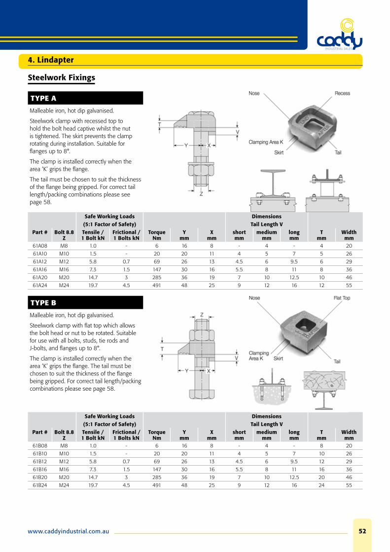
TYPE A
Malleable iron, hot dip galvanised.
Steelwork clamp with recessed top to hold the bolt head captive whilst the nut is tightened. The skirt prevents the clamp rotating during installation. Suitable for fl anges up to 8°.
The clamp is installed correctly when the area ‘K’ grips the fl ange.
The tail must be chosen to suit the thickness of the fl ange being gripped. For correct tail length/packing combinations please see page 58.
Safe Working Loads Dimensions(5:1 Factor of Safety) Tail Length V
Part # Bolt 8.8Z
Tensile / 1 Bolt kN
Frictional / 1 Bolts kN
Torque Nm
Y mm
X mm
short mm
mediummm
longmm
Tmm
Widthmm
61A08 M8 1.0 - 6 16 8 - 4 - 4 20
61A10 M10 1.5 - 20 20 11 4 5 7 5 26
61A12 M12 5.8 0.7 69 26 13 4.5 6 9.5 6 29
61A16 M16 7.3 1.5 147 30 16 5.5 8 11 8 36
61A20 M20 14.7 3 285 36 19 7 10 12.5 10 46
61A24 M24 19.7 4.5 491 48 25 9 12 16 12 55
TYPE B
Malleable iron, hot dip galvanised.
Steelwork clamp with fl at top which allows the bolt head or nut to be rotated. Suitable for use with all bolts, studs, tie rods and J-bolts, and fl anges up to 8°.
The clamp is installed correctly when the area ‘K’ grips the fl ange. The tail must be chosen to suit the thickness of the fl ange being gripped. For correct tail length/packing combinations please see page 58.
Safe Working Loads Dimensions(5:1 Factor of Safety) Tail Length V
Part # Bolt 8.8Z
Tensile / 1 Bolt kN
Frictional / 1 Bolts kN
Torque Nm
Y mm
X mm
short mm
mediummm
longmm
Tmm
Widthmm
61B08 M8 1.0 - 6 16 8 - 4 - 8 20
61B10 M10 1.5 - 20 20 11 4 5 7 10 26
61B12 M12 5.8 0.7 69 26 13 4.5 6 9.5 12 29
61B16 M16 7.3 1.5 147 30 16 5.5 8 11 16 36
61B20 M20 14.7 3 285 36 19 7 10 12.5 20 46
61B24 M24 19.7 4.5 491 48 25 9 12 16 24 55

Phone: 08 9475 085553
Accessories for Type A and B
TYPE CW - CLIPPED WASHER
Mild Steel, hot dip galvanised.
Packing used to adjust the tail length of the clamp to meet differing beam fl ange thicknesses.
Dimensions
Order example: CW08 BZP
Part # Bolt Z
Y mm
X mm
Tmm
Width mm
61CW08 M8 4 9,5 2 19
61CW10 M10 5 14 2 25
61CW12 M12 6 19.5 2.5 31
61CW16 M16 8 17.5 3 38
61CW20 M20 10 22 4 44
61CW24 M24 12 29 4 57
TYPE P1 SHORT / P2 SHORT
Mild Steel, malleable iron, hot dip galvanised.
Packing used to adjust the tail length of the clamp to meet differing beam fl ange thicknesses.
Part # Dimensions
Order example: P1S16 HDG
P1 P2 Bolt Z
Y mm
X mm
TP1mm
TP2mm
Width mm
61P1S08 P2S08 M8 4 10 4 8 21
61P1S10 P2S10 M10 5 13 5 10 24
61P1S12 P2S12 M12 6 16 6 12 30
61P1S16 P2S16 M16 8 21 8 16 35
61P1S20 P2S20 M20 10 23 10 20 43
61P1S24 P2S24 M24 12 32 12 24 54
4. Lindapter

www.caddyindustrial.com.au 54
4. Lindapter
Steelwork Fixings
TYPE AF
High friction clamp with recessed top to hold bolt head captive whilst the nut is tightened. Can be combined with type CF. The skirt prevents the clamp rotating during installation. The tail of the AF spans across slotted holes. For fl anges up to 10°. Washer type AFW available (see illustration).
For correct tail length/packing combinations please see page 58.
Safe Working LoadsFactor of Safety Dimensions
(5:1) (2:1)Part # Bolt Tensile /
1 BoltFrictional1) /
2 BoltsTail Length V T
Z Grade
kN
Painted Steelwork2)
kN
Galv. Steelwork
kN Torque
NmY
mmX
mmshort mm
mediummm
Type AFmm
Type AF with AFWmm
Widthmm
61AF12 M12 8.8 8.5 3.4 3.9 90 29 27 5 12.5 17 22 39
61AF16 M16 8.8 16.0 8.0 10.0 240 35 37 8 15 22 27 49
61AF20 M20 8.8 26.3 13.0 16.0 470 40 39 10 18 25 31 56
61AF24 M24 8.8 40.0 24.0 30.0 800 48 60 15 30 32 42 82
61AF12 M12 10.94) 10.0 4.0 5.2 130 29 27 5 12.5 17 22 39
61AF16 M16 10.94) 19.5 11.0 12.0 300 35 37 8 15 22 27 49
61AF20 M20 10.94) 30.0 20.0 25.0 647 40 39 10 18 25 31 56
61AF24 M24 10.94) 62.53) 28.0 35.0 1000 48 60 15 30 32 42 82

Phone: 08 9475 085555
Accessories for Type AF
TYPE AFCW
Mild Steel, hot dip galvanised.
Packing used to adjust the tail length of the clamp to meet differing beam fl ange thicknesses; has a slight bend along its centre line which fl attens out during installation.
Order example: AF12CW
Dimensions
Part # Bolt Z
Y mm
X mm
Tmm
Width mm
61AF12CW M12 7 33 2 40
61AF16CW M16 8 40 2 50
61AF20CW M20 9.5 40.5 2 55
TYPE AFP1 / AFP2
Mild Steel, hot dip galvanised.
Packing used to adjust the tail length of the clamp to meet differing beam fl ange thicknesses.
Order example: AF12P1
Part # Dimensions
P1 P2 Bolt Z
Y mm
X mm
TP1mm
TP2mm
Width mm
61AF12P1 61AF12P2 M12 7 33 5 10 40
61AF16P1 61AF16P2 M16 8 42 5 10 52
61AF20P1 61AF20P2 M20 9.5 45.5 5 10 56
61AF24P1 61AF24P2 M24 12 73 5 10 85
TYPE AFW
SG iron, malleable iron, hot dip galvanised.
Washer fi lling the recess of the type AF.
Additionally it features two projections which, when the AFW is inverted, will captivate the larger hexagons of 10.9 bolts. (M12 – M20 only).
M24 version has no projections.
Order example: AFW12
Part # Bolt Z
DimensionsT
mm61AFW12 M12 5
61AFW16 M16 5
61AFW20 M20 6
61AFW24 M24 10
4. Lindapter
www.caddyindustrial.com.au 56
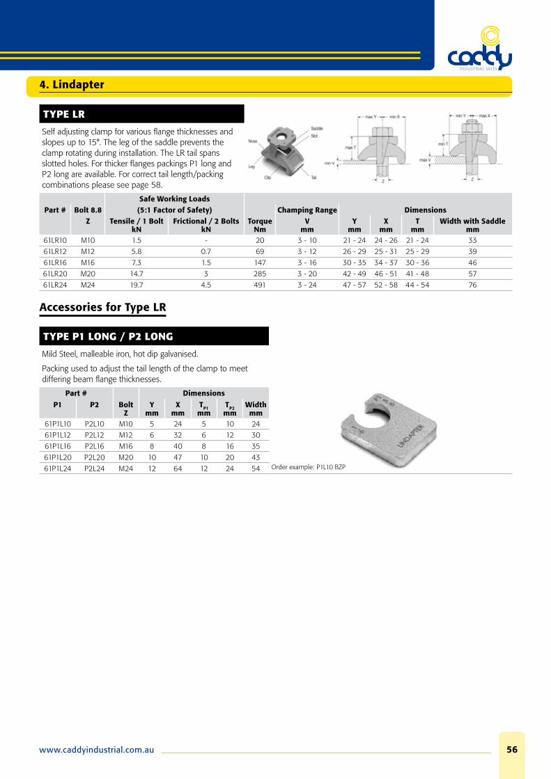
TYPE LR
Self adjusting clamp for various fl ange thicknesses and slopes up to 15°. The leg of the saddle prevents the clamp rotating during installation. The LR tail spans slotted holes. For thicker fl anges packings P1 long and P2 long are available. For correct tail length/packing combinations please see page 58.
Safe Working LoadsPart # Bolt 8.8 (5:1 Factor of Safety) Champing Range Dimensions
Z Tensile / 1 BoltkN
Frictional / 2 BoltskN
TorqueNm
Vmm
Y mm
X mm
Tmm
Width with Saddlemm
61LR10 M10 1.5 - 20 3 - 10 21 - 24 24 - 26 21 - 24 33
61LR12 M12 5.8 0.7 69 3 - 12 26 - 29 25 - 31 25 - 29 39
61LR16 M16 7.3 1.5 147 3 - 16 30 - 35 34 - 37 30 - 36 46
61LR20 M20 14.7 3 285 3 - 20 42 - 49 46 - 51 41 - 48 57
61LR24 M24 19.7 4.5 491 3 - 24 47 - 57 52 - 58 44 - 54 76
Accessories for Type LR
TYPE P1 LONG / P2 LONG
Mild Steel, malleable iron, hot dip galvanised.
Packing used to adjust the tail length of the clamp to meet differing beam fl ange thicknesses.
Part # Dimensions
Order example: P1L10 BZP
P1 P2 Bolt Z
Y mm
X mm
TP1mm
TP2mm
Width mm
61P1L10 P2L10 M10 5 24 5 10 24
61P1L12 P2L12 M12 6 32 6 12 30
61P1L16 P2L16 M16 8 40 8 16 35
61P1L20 P2L20 M20 10 47 10 20 43
61P1L24 P2L24 M24 12 64 12 24 54
4. Lindapter

Phone: 08 9475 085557
Steelwork Fixings
TYPE BR
Order example: BR12 short HDG
Malleable iron, hot dip galvanised.
Versatile clamp for steel beams or rails. The skirt prevents the clamp rotating during installation. The BR tail spans slotted holes. Suitable for fl anges up to 8°.
Safe Working Loads Dimensions(5:1 Factor of Safety) Tail Length V
Part # Bolt 8.8Z
Tensile / 1 Bolt kN
Frictional / 2 Bolts kN
Torque Nm
Y mm
X mm
short mm
mediummm
Tmm
Widthmm
61BR12 12 5.8 0.7 69 26 13 4 6 13 29
61BR16 16 7.3 1.5 147 30 16 6 8 16 35
61BR20 20 14.7 3 285 36 19 7 10 19 42
61BR24 24 19.7 4.5 491 48 25 9 12 25 54
TYPE F9
Order example: F910NC HDG
Malleable iron, hot dip galvanised.
Flange Clamp for connecting all types of parallel running steelwork with fl anges of the same width. Can be used with bolts or alternatively with threaded rod.
Not suitable for tapered fl anges.
Part # Safe Working Loadswith without Bolt 4.6 (5:1 Factor of Safety) Clamping Range DimensionsBolt Bolt Z Tensile / 1 Bolt
kNTorque
NmW
mmX
mmV
mmT
mmWidthmm
61F910NC F910NB M10 2 20 19 - 42 25 13 19 24
61F912NC F912NB M12 2.8 39 26 - 60 35 17 24 30
61F916NC F916NB M16 5.6 93 29 - 69 43 21 28 35
61F920NC F920NB M20 8.4 177 32 - 82 51 25 35 44
61F924NC F924NB M24 14.0 235 45 - 95 76 38 55 63
4. Lindapter

www.caddyindustrial.com.au 58
BOLT LENGTH CALCULATION FOR A STANDARD LINDAPTER GIRDER CLAMP, EXAMPLE SHOWS TYPE A AND B M20
To calculate the bolt length all parts the bolt will go through have to be added up. The next longer standard bolt length should be used.
CORRECT INSTALLATION OF TYPES A AND B
Showing type A as an example
Maximum tail length tolerance of -1mm (up to M16) and -1.5mm (M20, M24) before applying the torque is acceptable.
On 6º and 8º slopes types A and B require a special tail length/packing combination which will allow the clamp to tilt back slightly. For applications above 8° please see types AF, LR and LS.
TAIL LENGTH
The different tail length can be identifi ed by a code of dimples underneath the clamps.
4. Lindapter

Phone: 08 9475 085559
4. Lindapter
Typical Applications

www.caddyindustrial.com.au 60
4. Lindapter
Typical Applications

Phone: 08 9475 085561
Cavity Fixings
TYPE HB - HOLLO-BOLT®
Steel, bright zinc plated plus JS 500 Steel, hot dip galvanised Stainless Steel Grade 316.
Suitable for hollow sections, tubes and where access is available from one side only. For high corrosion protection the Hollo-Bolt® comes with additional JS500 protection as standard or hot dip galvanised.
Sizes M16 and M20 have a patented collapse mechanism for optimised clamping force. Speedy installation with standard tools and for the Type Hollo-Bolt® Flush Fit with installation nut. (One free per box)
Awarded the Design Council’s Millennium Product status for innovation in the year 2000.
4. Lindapter
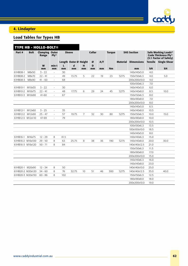
www.caddyindustrial.com.au 62
Load Tables for Types HB
TYPE HB - HOLLO-BOLT®Part # Bolt Clamping
RangeOuter Ply1)
Sleeve Collar Torque SHS Section Safe Working Loads2)
Code Thickness Ply1)
(5:1 Factor of Safety)Length Outer Ø Height Ø A/F Material Dimensions Tensile Single Shear
Wmm
min t mm
Lmm
dmm
Hmm
Dmm mm Nm mm kN kN
61HB08-1 M8x50 3 - 22 - 30 140x140x5.0 4.0
61HB08-2 M8x70 22 - 41 - 49 13.75 5 22 19 23 S275 150x150x6.3 4.0 5.0
61HB08-3 M8x90 41 - 60 - 68 200x200x10.0 4.0
100x100x6.3 7.0
61HB10-1 M10x55 3 - 22 - 30 140x140x5.0 6.0
61HB10-2 M10x75 22 - 41 - 48 17.75 6 29 24 45 S275 140x140x8.0 8.5 10.0
61HB10-3 M10x90 41-60 - 67 150x150x6.3 8.0
180x180x8.0 7.0
200x200x10.0 8.0
140x140x5.0 6.5
61HB12-1 M12x60 3 - 25 - 35 140x140x8.0 10.5
61HB12-2 M12x90 25 - 47 - 57 19.75 7 32 30 80 S275 150x150x6.3 10.0 15.0
61HB12-3 M12x110 47-69 - 79 180x180x8.0 10.0
200x200x10.0 10.5
100x100x6.3 13.5
100x100x10.0 18.5
140x140x5.0 8.0
61HB16-1 M16x75 12 - 29 8 41.5 140x140x6.3 15.0
61HB16-2 M16x100 29 - 50 8 63 25.75 8 38 36 190 S275 140x140x8.0 20.0 30.0
61HB16-3 M16x120 50 - 71 8 84 140x140x12.5 21.0
150x150x6.3 11.5
180x180x8.0 17.0
200x200x10.0 15.0
140x140x6.3 16.0
140x140x8.0 23.0
61HB20-1 M20x90 12 - 34 8 50 140x140x10.0 25.0
61HB20-2 M20x120 34 - 60 8 76 32.75 10 51 46 300 S275 140x140x12.5 35.0 40.0
61HB20-3 M20x150 60 - 86 8 102 150x150x6.3 12.5
180x180x8.0 18.0
200x200x10.0 19.0
4. Lindapter

Phone: 08 9475 085563
JOINTS IN STEEL CONSTRUCTION - SIMPLE CONNECTIONS
The tables on the previous page state the SWL with a 5:1 factor of safety and should be used for secondary applications, for primary design please consult the guide Joints in Steel Construction - Simple Connections.
The guide provides design guidance for the use of Hollo-Bolt® and gives essential information for structural steelwork connections for use in buildings designed by the ‘Simple Method’ i.e. braced frames where connections carry mainly shear and axial loads only.
BOLT DIAMETER, HOLE AND EDGE DISTANCES TYPE HB
ClearancePart # Hole Ø Hole Distances Edge
Distancesd1 min A min B B+C
mm mm mm mm61HB08 14 (+1.0 / -0.2) 35 13 B + C > 17.5
61HB10 18 (+1.0 / -0.2) 40 15 B + C > 22.5
61HB12 20 (+1.0 / -0.2) 50 18 B + C > 25.0
61HB16 26 (+2.0 / -0.2) 55 20 B + C > 32.5
61HB20 33 (+2.0 / -0.2) 70 25 B + C > 33.0
INSTALLATION HOLLO-BOLT™
1. Align pre-drilled fi xture and steelwork. Insert Hollo-Bolt® through fi xture and steelwork.
2. Grip the Hollo-Bolt® collar with an open ended spanner.
3. Using a torque wrench, tighten the central bolt to the recommended torque.
4. Lindapter

www.caddyindustrial.com.au 64
Floor Fixings
TYPE FF - FLOORFAST®
Malleable iron, Stainless Steel Grade 316, bright zinc plated / hot dip galvanised.
The product consists of a malleable iron body casting with a countersunk socket screw; the eccentric stepped web of the casting allows it to lock under the steelwork providing full face contact when torque is applied.
For thicker fl anges packing pieces will be supplied.
Lloyds’ Register Type Approval covers clamping force and vibration. Order example: FF12 HDG
Countersunk
Part # Bolt1)Floorplate Thickness
Flange Thickness Hole Ø
Countersunk Ø for Bolt Countersunk Depth for Bolt HexagonKeyBZP HDG BZP HDG Torque
Z tmm mm
dmm
Dmm
t1mm Nm mm
61FF08 M8 4.5 - 12 3 - 15 9 17 - 4 - 11 5
61FF10 M10 5 - 12 3 - 15 11 21 19 5 4 22 6
61FF12 M12 6 - 12 3 - 15 13.5 25 23 5.8 4.8 22 8
1) In hot dip galvanised (M10 and M12) a slotted countersunk screw is supplied.
TYPE GF - GRATE-FAST®
Body: Malleable iron, mechanical galvanised Top Hat: Mild Steel, mechanical galvanised.
Grating fi xing for rectangular open bar grating with cast main body giving superior clamping force.
GF10 with wider top-hat bracket for different grating sizes.
GF210 for use with 30mm width fl oor grating bars only.
GF08 with stainless steel top-hat bracket for GRP grating.
Lloyd’s Register Type Approval covers clamping force and vibration.
Part # Bolt Flange Grating Bar Depth
Grating Bar Width
Bar Distance
Body Width
Torque HexagonKey
Z Tmm
Dmm
Wmm
Xmm mm Nm mm
61GF08 M8 3 - 19 22 - 38 5 - 10 19 - 48 16 5 6
61GF10 M10 3 - 19 20 - 30 3 - 7 25 - 45 20 11 8
61GF210 M10 3 - 19 19 - 32 3 - 6.5 30 20 11 8
4. Lindapter
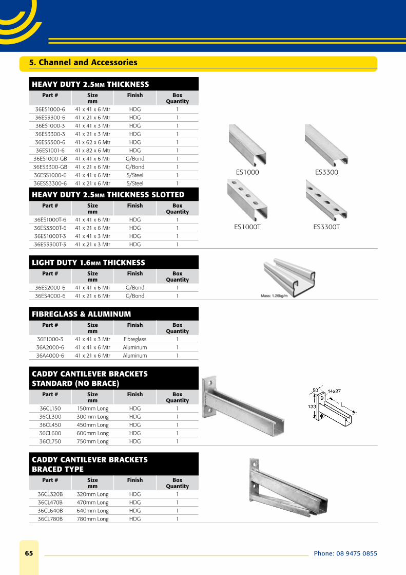
Phone: 08 9475 085565
HEAVY DUTY 2.5MM THICKNESSPart # Size
mmFinish Box
Quantity36ES1000-6 41 x 41 x 6 Mtr HDG 1
36ES3300-6 41 x 21 x 6 Mtr HDG 1
36ES1000-3 41 x 41 x 3 Mtr HDG 1
36ES3300-3 41 x 21 x 3 Mtr HDG 1
36ES5500-6 41 x 62 x 6 Mtr HDG 1
36ES1001-6 41 x 82 x 6 Mtr HDG 1
36ES1000-GB 41 x 41 x 6 Mtr G/Bond 1
36ES3300-GB 41 x 21 x 6 Mtr G/Bond 1
36ESS1000-6 41 x 41 x 6 Mtr S/Steel 1
36ESS3300-6 41 x 21 x 6 Mtr S/Steel 1
HEAVY DUTY 2.5MM THICKNESS SLOTTED Part # Size
mmFinish Box
Quantity36ES1000T-6 41 x 41 x 6 Mtr HDG 1
36ES3300T-6 41 x 21 x 6 Mtr HDG 1
36ES1000T-3 41 x 41 x 3 Mtr HDG 1
36ES3300T-3 41 x 21 x 3 Mtr HDG 1
LIGHT DUTY 1.6MM THICKNESSPart # Size
mmFinish Box
Quantity36ES2000-6 41 x 41 x 6 Mtr G/Bond 1
36ES4000-6 41 x 21 x 6 Mtr G/Bond 1
FIBREGLASS & ALUMINUMPart # Size
mmFinish Box
Quantity36F1000-3 41 x 41 x 3 Mtr Fibreglass 1
36A2000-6 41 x 41 x 6 Mtr Aluminum 1
36A4000-6 41 x 21 x 6 Mtr Aluminum 1
CADDY CANTILEVER BRACKETS STANDARD (NO BRACE)
Part # Sizemm
Finish Box Quantity
36CL150 150mm Long HDG 1
36CL300 300mm Long HDG 1
36CL450 450mm Long HDG 1
36CL600 600mm Long HDG 1
36CL750 750mm Long HDG 1
CADDY CANTILEVER BRACKETSBRACED TYPE
Part # Sizemm
Finish Box Quantity
36CL320B 320mm Long HDG 1
36CL470B 470mm Long HDG 1
36CL640B 640mm Long HDG 1
36CL780B 780mm Long HDG 1
5. Channel and Accessories

www.caddyindustrial.com.au 66
5. Channel and Accessories
INCA CLIPPart # Description Box
Quantity
Corrosion Protection – 7
36INC8 KIT INC8 100
SLOTTED ANGLE-ZPPart # Description Length Box
Quantity
Corrosion Protection – 1
36A3030 30 X 30 SLOTTED ANGLE 3 M 10
36A5050 50 X 50 SLOTTED ANGLE 3 M 10
ISSP PLATESPart # Description M Box
Quantity
Corrosion Protection – 1
36ISSP ISSP PLATE N/A 50
36ISSPMO6 ISSP KIT WITH ISN M6 10
36ISSPM08 ISSP KIT WITH ISN M8 10
36ISSPM10 ISSP KIT WITH ISN M10 10
CADDY JOINER-EXTERNAL–ZPPart # Description Box
Quantity
36J2377 External Channel Joiner 50
CADDY JOINER-INTERNAL–ZPPart # Description Box
Quantity
36J922 Internal Channel Joiner 50

Phone: 08 9475 085567
CHANNEL NUTS (NO SPRING ) Part # Size mm Finish Box Quantity
36NT06 M6 Trunking Nuts ZP 100
36NN06 M6 No Spring Nuts ZP 100
36NN08 M8 No Spring Nuts ZP 100
36NN10 M10 No Spring Nuts ZP 100
36NN12 M12 No Spring Nuts ZP 100
36NN16 M16 No Spring Nuts ZP 100
CHANNEL NUTS (SHORT SPRING )Part # Size mm Finish Box Quantity
36NS06 M6 Short Spring Nuts ZP 100
36NS08 M8 Short Spring Nuts ZP 100
36NS10 M10 Short Spring Nuts ZP 100
36NS12 M12 Short Spring Nuts ZP 100
36NS16 M16 Short Spring Nuts ZP 100
CHANNEL NUTS (LONG SPRING ) Part # Size mm Finish Box Quantity
36NL06 M6 Long Spring Nuts ZP 100
36NL08 M8 Long Spring Nuts ZP 100
36NL10 M10 Long Spring Nuts ZP 100
36NL12 M12 Long Spring Nuts ZP 100
36NL16 M16 Long Spring Nuts ZP 100
SLICK NUTSPart # Size mm Finish Box Quantity
36NS06 M6 Slick Nuts Caddy Coat 100
36NS08 M8 Slick Nuts Caddy Coat 100
36NS10 M10 Slick Nuts Caddy Coat 100
36NS12 M12 Slick Nuts Caddy Coat 100
PREP-MOUNTED CHANNEL NUTSPart # Size mm Finish Box Quantity
36NP08040 M8 x 40 Pre-Mounted Nut ZP 100
36NP10040 M10 x 40 Pre-Mounted Nut ZP 100
CLOSURE STRIPPart # Size mm Finish Box Quantity
36313309 Grey Suit 41mm Channel Plastic 1
36313310 White Suit 41mm Channel Plastic 1
36313311 Aluminium suit 41mm Channel Aluminum 1
CHANNEL END CAPSPart # Size mm Finish Box Quantity
362240 Grey Suit 41mm Channel Plastic 100
3624240 Grey Suit 21mm Channel Plastic 100
CHANNEL TROLLEYSPart # Size mm Finish Box Quantity
362749 2 Wheel Suit 41mm Channel ZP 25
362950 4 Wheel Suit 41mm Channel ZP 25
5. Channel and Accessories
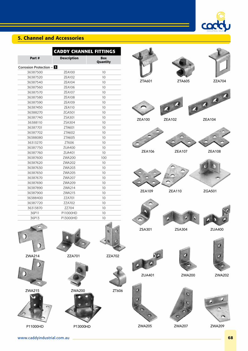
www.caddyindustrial.com.au 68
5. Channel and Accessories
CADDY CHANNEL FITTINGSPart # Description Box
Quantity
Corrosion Protection – 3
36387500 ZEA100 10
36387520 ZEA102 10
36387540 ZEA104 10
36387560 ZEA106 10
36387570 ZEA107 10
36387580 ZEA108 10
36387590 ZEA109 10
36387450 ZEA110 10
36388270 ZGA501 10
36387740 ZSA301 10
36388110 ZSA304 10
36387701 ZTA601 10
36387702 ZTA602 10
36388080 ZTA605 10
36313270 ZT606 10
36387750 ZUA400 10
36387760 ZUA401 10
36387600 ZWA200 100
36387620 ZWA202 10
36387630 ZWA203 10
36387650 ZWA205 10
36387670 ZWA207 10
36387690 ZWA209 10
36387890 ZWA214 10
36387900 ZWA215 10
36388400 ZZA701 10
36387720 ZZA702 10
36313870 ZZ704 10
36P11 P11000HD 10
36P13 P13000HD 10
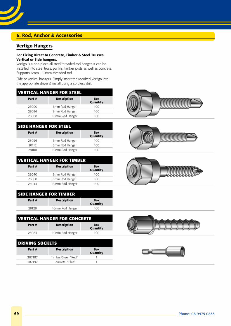
Phone: 08 9475 085569
6. Rod, Anchor & Accessories
Vertigo Hangers
For Fixing Direct to Concrete, Timber & Steel Trusses.Vertical or Side hangers.Vertigo is a one-piece all steel threaded rod hanger. It can be installed into steel truss, purlins, timber joists as well as concrete. Supports 6mm - 10mm threaded rod.
Side or vertical hangers. Simply insert the required Vertigo into the appropriate driver & install using a cordless drill.
VERTICAL HANGER FOR STEELPart # Description Box
Quantity28000 6mm Rod Hanger 100
28024 8mm Rod Hanger 100
28008 10mm Rod Hanger 100
SIDE HANGER FOR STEELPart # Description Box
Quantity28096 6mm Rod Hanger 100
28112 8mm Rod Hanger 100
28100 10mm Rod Hanger 100
VERTICAL HANGER FOR TIMBERPart # Description Box
Quantity28040 6mm Rod Hanger 100
28060 8mm Rod Hanger 100
28044 10mm Rod Hanger 100
SIDE HANGER FOR TIMBERPart # Description Box
Quantity28128 10mm Rod Hanger 100
VERTICAL HANGER FOR CONCRETEPart # Description Box
Quantity28084 10mm Rod Hanger 100
DRIVING SOCKETSPart # Description Box
Quantity287187 Timber/Steel “Red” 1
287197 Concrete “Blue” 1

www.caddyindustrial.com.au 70
6. Rod, Anchor & Accessories
Masonry Fasteners
STRIKE ANCHORSPart # Anchor Dia x Length
mmDrill Hole Dia
mmBox
Quantity
Corrosion Protection – 1
41ESA0850 8 x 50 8 60
41ESA1050 10 x 50 10 40
SLEEVE ANCHOR HEX NUT (DYNABOLT) ZPPart # Anchor Dia x Length
mmDrill Hole Dia
mmBox
Quantity41485010 6.5 x 25 6.5 100
41485050 6.5 x 36 6.5 100
41485250 8 x 40 8 100
41485300 8 x 65 8 100
41485440 10 x 40 10 100
41485450 10 x 50 10 100
41485475 10 x 75 10 50
41485600 10 x 97 10 50
41485760 12 x 60 12 50
DROP IN ANCHOR, FLANGED TYPE ZPPart # Anchor Dia x Length
mmDrill Hole Dia
mmBox
Quantity41525220 6 x 25 8 100
41525230 8 x 30 10 100
41525235 10 x 30 12 50
41525235B 10 x 30 12 500
41525260 12 x 50 15 50
41525270 16 x 65 20 25
ALL METAL DRIVE ANCHOR (METAL TAP-INS) ROUND HEAD Part # Anchor Dia x Length
mmDrill Hole Dia
mmBox
Quantity41545700 5 x 25 5 100
41545720 6.5 x 32 6.5 100
41545740 6.5 x 50 6.5 100
NYLON DRIVE ANCHOR (NYLON TAP-INS) ROUND HEAD Part # Anchor Dia x Length
mmDrill Hole Dia
mmBox
Quantity41545540 5 x 25 5 100
41545458 5 x 40 5 100
41545560 6.5 x 25 6.5 100
41545570 6.5 x 40 6.5 100
41545580 6.5 x 50 6.5 100
HEADLESS SCREW
Technical DataMaterial: Steel, electro-galvanised
Part # Type Thread Connection
Total Lengthmm
Box Quantity
41585080 M10/80mm M10 x 30 80 10041585100 M10/100mm M10 x 30 100 100
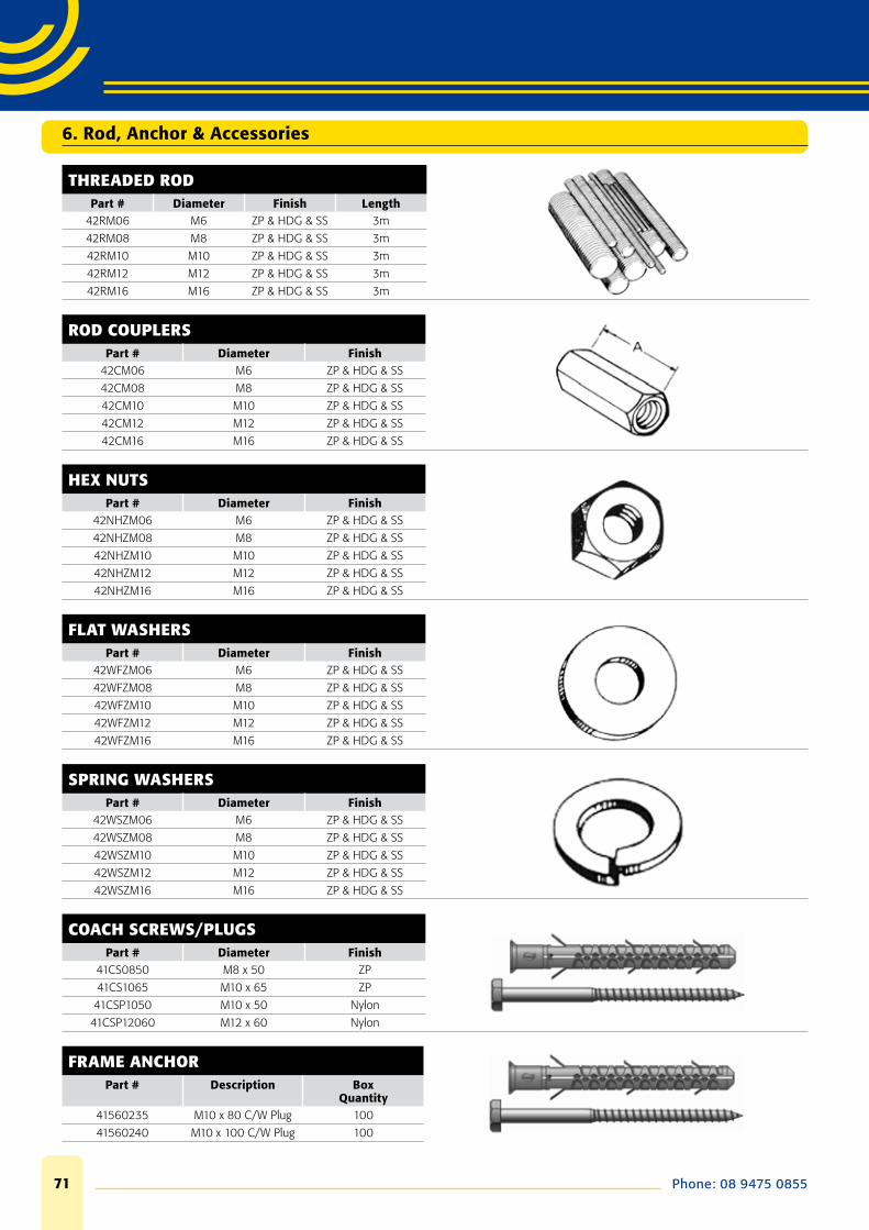
Phone: 08 9475 085571
6. Rod, Anchor & Accessories
THREADED RODPart # Diameter Finish Length
42RM06 M6 ZP & HDG & SS 3m
42RM08 M8 ZP & HDG & SS 3m
42RM10 M10 ZP & HDG & SS 3m
42RM12 M12 ZP & HDG & SS 3m
42RM16 M16 ZP & HDG & SS 3m
ROD COUPLERSPart # Diameter Finish
42CM06 M6 ZP & HDG & SS
42CM08 M8 ZP & HDG & SS
42CM10 M10 ZP & HDG & SS
42CM12 M12 ZP & HDG & SS
42CM16 M16 ZP & HDG & SS
HEX NUTSPart # Diameter Finish
42NHZM06 M6 ZP & HDG & SS
42NHZM08 M8 ZP & HDG & SS
42NHZM10 M10 ZP & HDG & SS
42NHZM12 M12 ZP & HDG & SS
42NHZM16 M16 ZP & HDG & SS
FLAT WASHERSPart # Diameter Finish
42WFZM06 M6 ZP & HDG & SS
42WFZM08 M8 ZP & HDG & SS
42WFZM10 M10 ZP & HDG & SS
42WFZM12 M12 ZP & HDG & SS
42WFZM16 M16 ZP & HDG & SS
SPRING WASHERSPart # Diameter Finish
42WSZM06 M6 ZP & HDG & SS
42WSZM08 M8 ZP & HDG & SS
42WSZM10 M10 ZP & HDG & SS
42WSZM12 M12 ZP & HDG & SS
42WSZM16 M16 ZP & HDG & SS
COACH SCREWS/PLUGSPart # Diameter Finish
41CS0850 M8 x 50 ZP
41CS1065 M10 x 65 ZP
41CSP1050 M10 x 50 Nylon
41CSP12060 M12 x 60 Nylon
FRAME ANCHORPart # Description Box
Quantity41560235 M10 x 80 C/W Plug 100
41560240 M10 x 100 C/W Plug 100
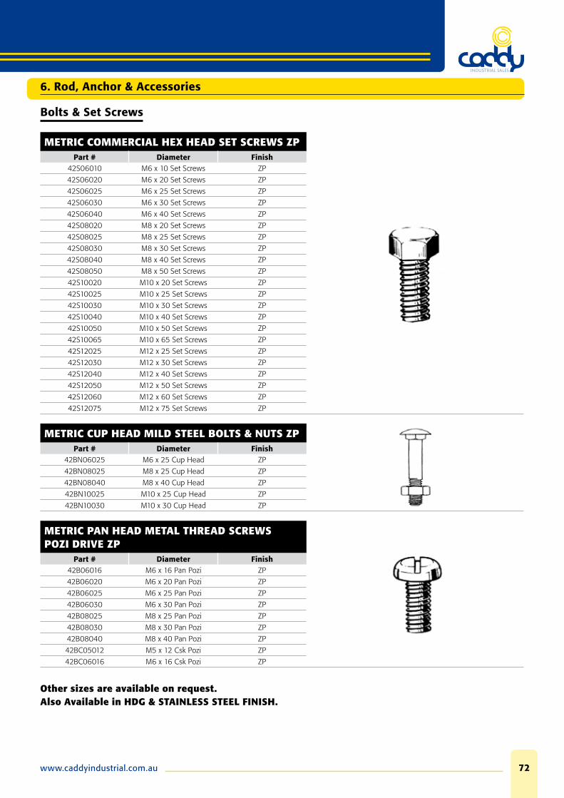
www.caddyindustrial.com.au 72
6. Rod, Anchor & Accessories
Bolts & Set Screws
METRIC COMMERCIAL HEX HEAD SET SCREWS ZPPart # Diameter Finish
42S06010 M6 x 10 Set Screws ZP
42S06020 M6 x 20 Set Screws ZP
42S06025 M6 x 25 Set Screws ZP
42S06030 M6 x 30 Set Screws ZP
42S06040 M6 x 40 Set Screws ZP
42S08020 M8 x 20 Set Screws ZP
42S08025 M8 x 25 Set Screws ZP
42S08030 M8 x 30 Set Screws ZP
42S08040 M8 x 40 Set Screws ZP
42S08050 M8 x 50 Set Screws ZP
42S10020 M10 x 20 Set Screws ZP
42S10025 M10 x 25 Set Screws ZP
42S10030 M10 x 30 Set Screws ZP
42S10040 M10 x 40 Set Screws ZP
42S10050 M10 x 50 Set Screws ZP
42S10065 M10 x 65 Set Screws ZP
42S12025 M12 x 25 Set Screws ZP
42S12030 M12 x 30 Set Screws ZP
42S12040 M12 x 40 Set Screws ZP
42S12050 M12 x 50 Set Screws ZP
42S12060 M12 x 60 Set Screws ZP
42S12075 M12 x 75 Set Screws ZP
METRIC CUP HEAD MILD STEEL BOLTS & NUTS ZPPart # Diameter Finish
42BN06025 M6 x 25 Cup Head ZP
42BN08025 M8 x 25 Cup Head ZP
42BN08040 M8 x 40 Cup Head ZP
42BN10025 M10 x 25 Cup Head ZP
42BN10030 M10 x 30 Cup Head ZP
METRIC PAN HEAD METAL THREAD SCREWS POZI DRIVE ZP
Part # Diameter Finish42B06016 M6 x 16 Pan Pozi ZP
42B06020 M6 x 20 Pan Pozi ZP
42B06025 M6 x 25 Pan Pozi ZP
42B06030 M6 x 30 Pan Pozi ZP
42B08025 M8 x 25 Pan Pozi ZP
42B08030 M8 x 30 Pan Pozi ZP
42B08040 M8 x 40 Pan Pozi ZP
42BC05012 M5 x 12 Csk Pozi ZP
42BC06016 M6 x 16 Csk Pozi ZP
Other sizes are available on request.Also Available in HDG & STAINLESS STEEL FINISH.
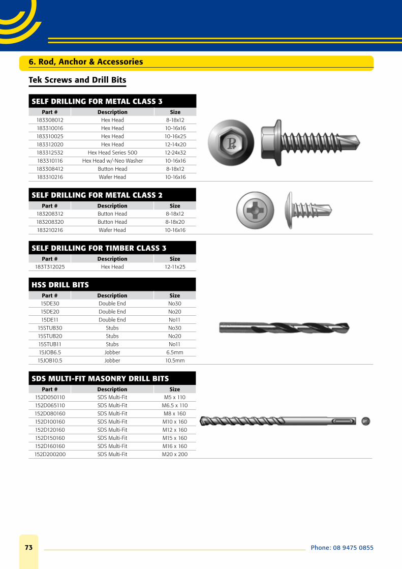
Phone: 08 9475 085573
6. Rod, Anchor & Accessories
Tek Screws and Drill Bits
SELF DRILLING FOR METAL CLASS 3Part # Description Size
183308012 Hex Head 8-18x12
183310016 Hex Head 10-16x16
183310025 Hex Head 10-16x25
183312020 Hex Head 12-14x20
183312532 Hex Head Series 500 12-24x32
183310116 Hex Head w/-Neo Washer 10-16x16
183308412 Button Head 8-18x12
183310216 Wafer Head 10-16x16
SELF DRILLING FOR METAL CLASS 2Part # Description Size
183208312 Button Head 8-18x12
183208320 Button Head 8-18x20
183210216 Wafer Head 10-16x16
SELF DRILLING FOR TIMBER CLASS 3Part # Description Size
183T312025 Hex Head 12-11x25
HSS DRILL BITSPart # Description Size15DE30 Double End No30
15DE20 Double End No20
15DE11 Double End No11
15STUB30 Stubs No30
15STUB20 Stubs No20
15STUB11 Stubs No11
15JOB6.5 Jobber 6.5mm
15JOB10.5 Jobber 10.5mm
SDS MULTI-FIT MASONRY DRILL BITSPart # Description Size
152D050110 SDS Multi-Fit M5 x 110
152D065110 SDS Multi-Fit M6.5 x 110
152D080160 SDS Multi-Fit M8 x 160
152D100160 SDS Multi-Fit M10 x 160
152D120160 SDS Multi-Fit M12 x 160
152D150160 SDS Multi-Fit M15 x 160
152D160160 SDS Multi-Fit M16 x 160
152D200200 SDS Multi-Fit M20 x 200

www.caddyindustrial.com.au 74
6. Rod, Anchor & Accessories
Pop Rivets
ALUMINIUM RIVETS WITH STEEL STEMPart # Description Size
06ASP402 3.2mm dia x 3.2 max grip 4-2
06ASP403 3.2mm dia x 4.8 max grip 4–3
06ASP404 3.2mm dia x 6.4 max grip 4–4
06ASP604 4.8mm dia x 6.4 max grip 6–4
ALUMINIUM SEALED RIVETPart # Description Size
06SR01-03295 3.2mm dia x 4.8 max grip 4-3
06SR01-4812 4.8mm dia x 8.0 max grip 6-5
STEEL RIVETS WITH STEEL STEMPart # Description Size
06SSP402 3.2mm dia x 3.2 max grip 4-2
06SSP403 3.2mm dia x 4.8 max grip 4–3
06SSP404 3.2mm dia x 6.4 max grip 4–4
06SSP504 4.2mm dia x 6.4 max grip 5–4
06SSP604 4.8mm dia x 6.4 max grip 6–4
S/STEEL RIVETS WITH S/STEEL STEMPart # Description Size
06CCP402 3.2mm dia x 3.2 max grip 4-2
06CCP403 3.2mm dia x 4.8 max grip 4–3
06CCP404 3.2mm dia x 6.4 max grip 4–4
06CCP604 4.8mm dia x 6.4 max grip 6–4
Other sizes and materials are available.
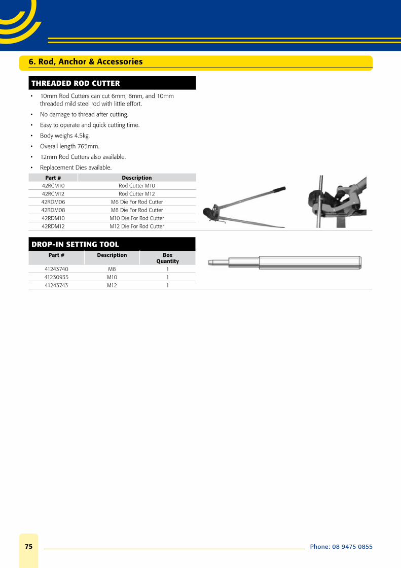
Phone: 08 9475 085575
6. Rod, Anchor & Accessories
THREADED ROD CUTTER
• 10mm Rod Cutters can cut 6mm, 8mm, and 10mm threaded mild steel rod with little effort.
• No damage to thread after cutting.
• Easy to operate and quick cutting time.
• Body weighs 4.5kg.
• Overall length 765mm.
• 12mm Rod Cutters also available.
• Replacement Dies available.
Part # Description42RCM10 Rod Cutter M10
42RCM12 Rod Cutter M12
42RDM06 M6 Die For Rod Cutter
42RDM08 M8 Die For Rod Cutter
42RDM10 M10 Die For Rod Cutter
42RDM12 M12 Die For Rod Cutter
DROP-IN SETTING TOOLPart # Description Box
Quantity41243740 M8 1
41230935 M10 1
41243743 M12 1


