
1
Control and Management of Heterogeneous
RATs in 5G Wireless Networks: An SDN/NFV
Approach
Akshatha Nayak M., Arghyadip Roy, Pranav Jha, and Abhay Karandikar
Abstract
Telecom operators have begun to use a heterogeneous mix of Radio Access Technologies (RATs)
for providing services to mobile subscribers. This development has emphasized the need for improved
inter-working among diverse RATs in the Fifth Generation (5G) wireless networks. In this article, we
provide a brief overview of ongoing efforts towards utilizing Software Defined Networking (SDN)
and Network Function Virtualization (NFV) for control and management of heterogeneous RATs in 5G
wireless networks. In addition, we also propose a novel SDN/NFV based architecture for unified control
and management of heterogeneous RATs in 5G wireless networks. The proposed architecture is scalable
and offers improved network performance over existing Heterogeneous Network (HetNet) architectures.
Finally, we present experimental results and highlight a few open research problems in this area.
I. INTRODUCTION
The rising popularity of data-intensive mobile applications such as social networking, video,
audio, etc., has led to the demand for higher data rates and an increased per capita data
usage [1]. In order to cater to the increased data traffic, mobile network operators are devising
newer techniques, such as, deploying low power small cells in hotspot areas or supplementing
cellular network deployments with Wireless Local Area Networks (WLANs) in unlicensed bands.
These developments have resulted in wireless networks comprising of diverse Radio Access
Technologies (RATs) and possessing Heterogeneous Network (HetNet) architectures.
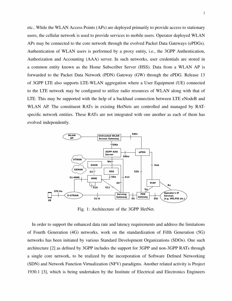
The existing Third Generation Partnership Project (3GPP) multi-RAT HetNet architecture is
illustrated in Fig. 1. It comprises of various RATs such as Long Term Evolution (LTE), WLAN,
The authors are with the Department of Electrical Engineering, Indian Institute of Technology Bombay, Mumbai-400076,India. e-mail: {akshatha, arghyadip, pranavjha, karandi}@ee.iitb.ac.in
arX
iv:1
801.
0381
9v1
[ee
ss.S
P] 4
Jan
201
8
2
etc.. While the WLAN Access Points (APs) are deployed primarily to provide access to stationary
users, the cellular network is used to provide services to mobile users. Operator deployed WLAN
APs may be connected to the core network through the evolved Packet Data Gateways (ePDGs).
Authentication of WLAN users is performed by a proxy entity, i.e., the 3GPP Authentication,
Authorization and Accounting (AAA) server. In such networks, user credentials are stored in
a common entity known as the Home Subscriber Server (HSS). Data from a WLAN AP is
forwarded to the Packet Data Network (PDN) Gateway (GW) through the ePDG. Release 13
of 3GPP LTE also supports LTE-WLAN aggregation where a User Equipment (UE) connected
to the LTE network may be configured to utilize radio resources of WLAN along with that of
LTE. This may be supported with the help of a backhaul connection between LTE eNodeB and
WLAN AP. The constituent RATs in existing HetNets are controlled and managed by RAT-
specific network entities. These RATs are not integrated with one another as each of them has
evolved independently.
E-UTRAN ServingGateway
MME
SGSN
HSS
UTRAN
GERAN
UE
LTE-UuGx
Operator's IPServices(e.g. IMS,PSS etc.)
PCRF
PDNGateway
S1-U
S10 S11
S3
S1-MME S6a
S4
S12
S5 SGi
Rx
Untrusted WLAN Access Gateway
3GPP AAAServer
Wx
SWm
S2b
SWnWLAN
AP
SWa
ePDG
Gxb
Fig. 1: Architecture of the 3GPP HetNet.
In order to support the enhanced data rate and latency requirements and address the limitations
of Fourth Generation (4G) networks, work on the standardization of Fifth Generation (5G)
networks has been initiated by various Standard Development Organizations (SDOs). One such
architecture [2] as defined by 3GPP includes the support for 3GPP and non-3GPP RATs through
a single core network, to be realized by the incorporation of Software Defined Networking
(SDN) and Network Function Virtualization (NFV) paradigms. Another related activity is Project
1930.1 [3], which is being undertaken by the Institute of Electrical and Electronics Engineers

3
(IEEE)1.
SDN [4] is a networking principle that abstracts the network into control and data planes.
The control plane of a network comprises of control and management elements and protocols,
whereas the data plane comprises of elements/functions that forward data. The two planes are
separated through a standardized interface. The standardized interface facilitates configuration
of data plane elements using policy-based rules and eliminates the need for vendor-specific
configurations. This interface can also expose the capabilities of network elements, which could
be used by third-party vendors for developing applications [2].
According to the 5G system requirements [2], the 5G network is expected to be scalable
and customizable to provision newer services. Scalability in networks can be realized by using
NFV [5] as it ensures that the Network Functions (NFs) can be upgraded or migrated as required.
NFV translates NFs running on specialized hardware into software that can be ported on to
general purpose hardware. An NF is a functional block within a network infrastructure, having
well-defined external interfaces and functional behavior. In existing networks, NFs are mostly
implemented over custom hardware, making network upgrades both expensive and challenging.
NFV enables the usage of off-the-shelf hardware for the implementation of NFs, thereby reducing
equipment cost and easing software migration.
SDN and NFV enable the creation of logical networks known as network slices (or "slices")
over a physical network infrastructure. A slice consists of a set of NFs and the corresponding
resources. It may possess specific network capabilities and provide definite services. As each
slice can be isolated from others, multiple operators can share a common physical infrastructure.
The 5G network is also expected to support applications with large variations in Quality of
Service (QoS) requirements. This can be achieved using separate slices over the same physical
infrastructure. NFV along with SDN facilitates a flexible network, where slices can be dynami-
cally provisioned and migrated at need. Newer applications can also be easily deployed into the
network as per customer requirements.
In this article, we present an SDN/NFV based architecture which unifies the control and
management of heterogeneous RATs in a 5G network. It also provides the flexibility to support
other future RATs. The proposed architecture comprises of an SDN Controller which controls and
1The IEEE P1930.1 working group, which aims to bring about interoperability across network equipment of disparate vendorsthrough unified control and management of different IEEE RATs is chaired by one of the authors of this article (Pranav Jha).URL: https://standards.ieee.org/develop/project/1930.1.html

4
manages different RATs in a unified manner. Probable scalability issues due to the aggregation
of control at a single point are eliminated with the help of multiple slices in the network. A
Slice Manager (SM) splits the end-to-end network into multiple slices (logical networks), each
possessing individual control and data plane functions. Additionally, NFs are decoupled from
custom hardware platforms and virtualized with the help of an Orchestrator.
The rest of the article is organized as follows. Section II describes the related work and
standardization efforts towards integrating SDN/NFV into 5G networks. Section III provides
the details of the proposed SDN/NFV based architecture to control and manage 5G networks.
Advantages of this architecture are described in the subsequent section. A few experimental
results are provided in Section V. Section VI concludes the article.
II. RELATED WORK AND STANDARDIZATION EFFORTS ON SDN/NFV IN 5G NETWORKS
Some of the existing literature describing the role of SDN and NFV in 5G networks is
presented in this section. The available literature can be classified into two categories. The
first set of papers [6]–[8] describe 5G architectures, built by modifying the existing 4G HetNets.
The authors in [6] describe a layered architecture for virtualizing the core and access networks
in HetNets. They propose to use an open northbound Application Programming Interface (API)
for programming the virtual HetNets using the OpenFlow protocol. In [7], the authors introduce
a new logical control path for configuring flows across the radio interfaces without any changes
to existing network elements. In [8], the authors propose to embed the SDN Controller at each
node for improving the system resiliency and signaling latency.
The second set of papers [9]–[11], propose clean slate architectures for the 5G network. The
authors in [9] propose an architecture for the next-generation cellular networks that support
HetNets. This architecture claims to save backhaul capacity by caching content at the network
edge. In another work [10], the authors survey a few SDN/NFV based 5G architectures. One of
the architectures transforms the switches and base stations into NFs virtualized by hypervisors.
NFs can then be aggregated and implemented in data centers. This approach is similar to another
popular architecture known as Cloud-RAN (C-RAN) [11]. C-RAN aims to relegate network
processing including baseband functions to the cloud. Another architecture in [10] identifies
basic logical functions for both control and data planes. It also introduces additional NFs for
management of cache forwarding and data analytics.
5
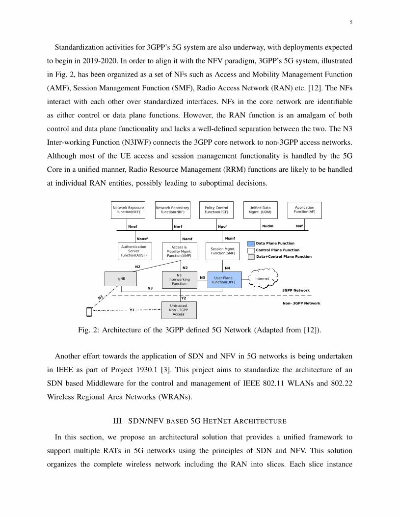
Standardization activities for 3GPP’s 5G system are also underway, with deployments expected
to begin in 2019-2020. In order to align it with the NFV paradigm, 3GPP’s 5G system, illustrated
in Fig. 2, has been organized as a set of NFs such as Access and Mobility Management Function
(AMF), Session Management Function (SMF), Radio Access Network (RAN) etc. [12]. The NFs
interact with each other over standardized interfaces. NFs in the core network are identifiable
as either control or data plane functions. However, the RAN function is an amalgam of both
control and data plane functionality and lacks a well-defined separation between the two. The N3
Inter-working Function (N3IWF) connects the 3GPP core network to non-3GPP access networks.
Although most of the UE access and session management functionality is handled by the 5G
Core in a unified manner, Radio Resource Management (RRM) functions are likely to be handled
at individual RAN entities, possibly leading to suboptimal decisions.
Network Exposure Function(NEF)
Network Repository Function(NRF)
Policy ControlFunction(PCF)
Unified DataMgmt. (UDM)
ApplicationFunction(AF)
AuthenticationServer
Function(AUSF)
Access &Mobility Mgmt.Function(AMF)
Session Mgmt.Function(SMF)
N3Interworking
Function
User PlaneFunction(UPF)
Internet
Nnef
Nausf
Nnrf Npcf Nudm Naf
Namf Nsmf
N2 N4
N3
N2
Data+Control Plane Function
Data Plane Function
Control Plane Function
gNB
Y2
Y1
N1
Untrusted Non - 3GPP
Access
3GPP Network
Non- 3GPP Network
N3
Fig. 2: Architecture of the 3GPP defined 5G Network (Adapted from [12]).
Another effort towards the application of SDN and NFV in 5G networks is being undertaken
in IEEE as part of Project 1930.1 [3]. This project aims to standardize the architecture of an
SDN based Middleware for the control and management of IEEE 802.11 WLANs and 802.22
Wireless Regional Area Networks (WRANs).
III. SDN/NFV BASED 5G HETNET ARCHITECTURE
In this section, we propose an architectural solution that provides a unified framework to
support multiple RATs in 5G networks using the principles of SDN and NFV. This solution
organizes the complete wireless network including the RAN into slices. Each slice instance
6
comprises of data plane functions called Base Stations (BSs) and GWs and a generic control
plane function known as the Multi-RAT SDN Controller. The functions may be shared across
slices.
The Controller controls the BSs and GWs within the slice. It is also responsible for exchanging
control plane messages with User Equipments (UEs), controlling the data plane functions and
providing data flow configurations. It may also exchange control plane messages with Controllers
which are a part of other slices. BSs are responsible for forwarding signaling/control plane
messages that are exchanged between the UEs and the Controller. They are also responsible for
forwarding user plane data (application specific data, e.g., VoIP, video streams, HTTP messages)
exchanged between UEs and external data networks via the GWs. BSs are devoid of control
and management capabilities, which are conventionally present in the RAN nodes of wireless
networks (e.g., Radio Resource Control (RRC) functionality in 3GPP LTE eNodeB or in the
5G gNB). These capabilities are implemented in the Controller. Since BSs are responsible for
communication with UEs over the radio interface, the protocol stack present in a BS depends
upon the nature of the underlying RAT, and therefore for every supported RAT, a specific type
of BS may be required in the network. GWs are generic data plane nodes, which are responsible
for forwarding user plane data, received from UEs via the BSs, towards external data networks.
A GW supports data forwarding for all types of UEs and all types of RATs.
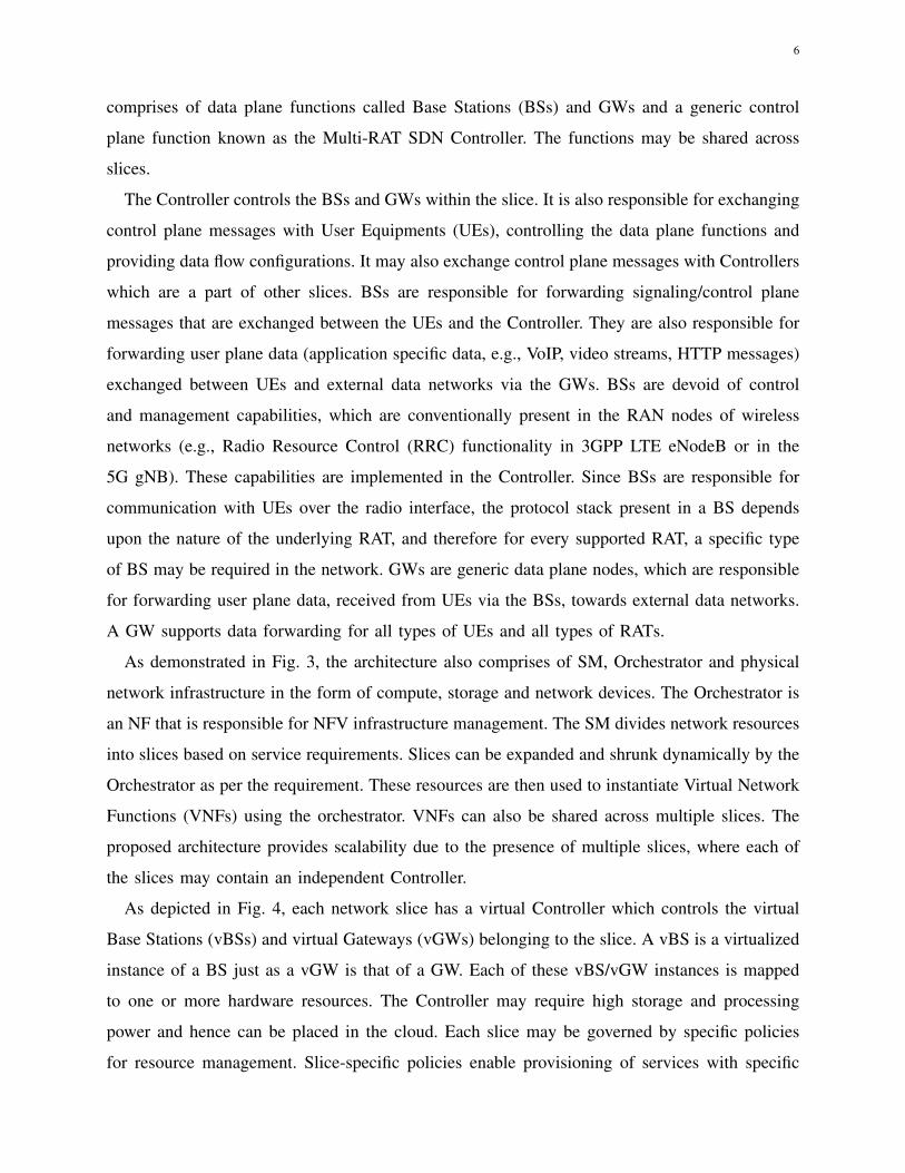
As demonstrated in Fig. 3, the architecture also comprises of SM, Orchestrator and physical
network infrastructure in the form of compute, storage and network devices. The Orchestrator is
an NF that is responsible for NFV infrastructure management. The SM divides network resources
into slices based on service requirements. Slices can be expanded and shrunk dynamically by the
Orchestrator as per the requirement. These resources are then used to instantiate Virtual Network
Functions (VNFs) using the orchestrator. VNFs can also be shared across multiple slices. The
proposed architecture provides scalability due to the presence of multiple slices, where each of
the slices may contain an independent Controller.
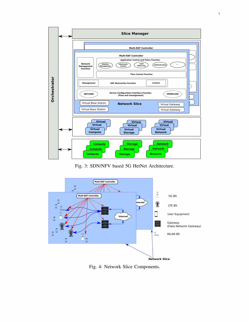
As depicted in Fig. 4, each network slice has a virtual Controller which controls the virtual
Base Stations (vBSs) and virtual Gateways (vGWs) belonging to the slice. A vBS is a virtualized
instance of a BS just as a vGW is that of a GW. Each of these vBS/vGW instances is mapped
to one or more hardware resources. The Controller may require high storage and processing
power and hence can be placed in the cloud. Each slice may be governed by specific policies
for resource management. Slice-specific policies enable provisioning of services with specific
7
Orc
hestr
ato
r
Slice Manager
Virtual ComputeVirtual
ComputeVirtual Compute
Virtual ComputeVirtual
ComputeVirtual Storage
Virtual ComputeVirtual
ComputeVirtual Network
Compute
Compute
Compute
Network
Network
Network
Storage
Storage
Storage
Virtual Base Station
Virtual Base Station
Virtual Gateway
Multi-RAT Controller
Application Control and Policy Function
Flow Control Function
Management RAT Abstraction Function Control
NetworkManagement
Function
Device Configuration Interface Function (Flow and management)
NETCONF OPENFLOW
MobilityManagement
....AuthenticationLoad
BalancingAdmission
Control
Network Slice
Virtual GatewayVirtual Base Station
Virtual Base Station
Virtual Gateway
Multi-RAT Controller
Application Control and Policy Function
Flow Control Function
Management RAT Abstraction Function Control
NetworkManagement
Function
Device Configuration Interface Function (Flow and management)
NETCONF OPENFLOW
MobilityManagement
....AuthenticationLoad
BalancingAdmission
Control
Network Slice
Virtual Gateway
Fig. 3: SDN/NFV based 5G HetNet Architecture.
Network Slice
User Equipment
LTE BS
Gateway(Data Network Gateway)
WLAN BS
5G BS
Internet
Multi-RAT Controller
Internet
Multi-RAT Controller
Fig. 4: Network Slice Components.
8
Multi-RAT Controller
Application Control and Policy Function
Flow Control Function
Management RAT Abstraction Function Control
NetworkManagement
Function
Device Configuration Interface Function (Flow and management)
NETCONF OPENFLOW
MobilityManagement
....AuthenticationLoad
BalancingAdmission
Control
Fig. 5: Architecture of the virtual SDN Controller.
QoS requirements.
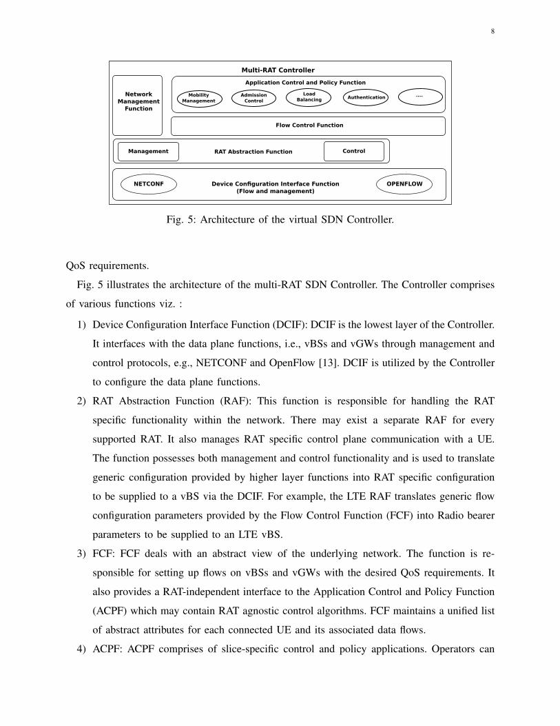
Fig. 5 illustrates the architecture of the multi-RAT SDN Controller. The Controller comprises
of various functions viz. :
1) Device Configuration Interface Function (DCIF): DCIF is the lowest layer of the Controller.
It interfaces with the data plane functions, i.e., vBSs and vGWs through management and
control protocols, e.g., NETCONF and OpenFlow [13]. DCIF is utilized by the Controller
to configure the data plane functions.
2) RAT Abstraction Function (RAF): This function is responsible for handling the RAT
specific functionality within the network. There may exist a separate RAF for every
supported RAT. It also manages RAT specific control plane communication with a UE.
The function possesses both management and control functionality and is used to translate
generic configuration provided by higher layer functions into RAT specific configuration
to be supplied to a vBS via the DCIF. For example, the LTE RAF translates generic flow
configuration parameters provided by the Flow Control Function (FCF) into Radio bearer
parameters to be supplied to an LTE vBS.
3) FCF: FCF deals with an abstract view of the underlying network. The function is re-
sponsible for setting up flows on vBSs and vGWs with the desired QoS requirements. It
also provides a RAT-independent interface to the Application Control and Policy Function
(ACPF) which may contain RAT agnostic control algorithms. FCF maintains a unified list
of abstract attributes for each connected UE and its associated data flows.
4) ACPF: ACPF comprises of slice-specific control and policy applications. Operators can
9
introduce new applications/policies into a specific slice without affecting other network
slices. A RAT independent interface between ACPF and the FCF enables third-party
vendors to implement new algorithms without the necessity of understanding the underlying
network complexity.
5) Network Management Function (NMF): NMF is responsible for the management function-
ality in the network. It provides configuration parameters to forwarding plane functions
(vBS and vGW) via RAF and the underlying DCIF utilizing the NETCONF protocol, e.g.,
LTE cell-specific configuration parameters are provided to the LTE vBS by NMF.
A. Network Function Management in the Proposed Controller
This section provides details of different control and management procedures in the proposed
network architecture. LTE and WLAN have been used as reference RATs here to describe
different procedures related to the proposed architecture. These procedures can also be extended
to the 5G New Radio (NR) RAT once that is standardized.
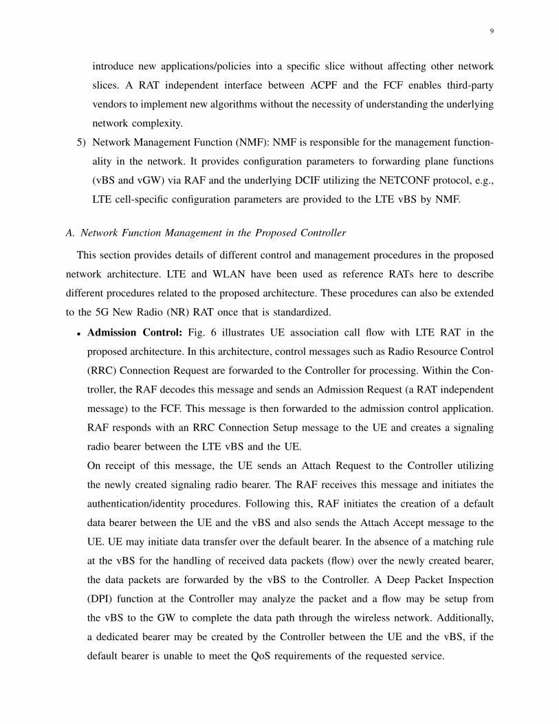
• Admission Control: Fig. 6 illustrates UE association call flow with LTE RAT in the
proposed architecture. In this architecture, control messages such as Radio Resource Control
(RRC) Connection Request are forwarded to the Controller for processing. Within the Con-
troller, the RAF decodes this message and sends an Admission Request (a RAT independent
message) to the FCF. This message is then forwarded to the admission control application.
RAF responds with an RRC Connection Setup message to the UE and creates a signaling
radio bearer between the LTE vBS and the UE.
On receipt of this message, the UE sends an Attach Request to the Controller utilizing
the newly created signaling radio bearer. The RAF receives this message and initiates the
authentication/identity procedures. Following this, RAF initiates the creation of a default
data bearer between the UE and the vBS and also sends the Attach Accept message to the
UE. UE may initiate data transfer over the default bearer. In the absence of a matching rule
at the vBS for the handling of received data packets (flow) over the newly created bearer,
the data packets are forwarded by the vBS to the Controller. A Deep Packet Inspection
(DPI) function at the Controller may analyze the packet and a flow may be setup from
the vBS to the GW to complete the data path through the wireless network. Additionally,
a dedicated bearer may be created by the Controller between the UE and the vBS, if the
default bearer is unable to meet the QoS requirements of the requested service.
10
UE LTEvBS AAA Multi-RAT
Controller
1. RRC Connection Request
2. RRC Connection Setup Response
vGW
Internet
Signaling flow created
Control
Signals
Data
5. Authentication Request/Response
6. Identity Request/Response
Data Flow
Perform DPI andcreate the required flow(s)
4. Attach Request
7. Attach Accept
8. Create default data bearer between vBS and UE
Buffer data packet and forward to Controller to setup flow(s)
Forwarded data flow
9. Create data flow(s) on vBS and vGW
Data Flow(s)
Create dedicated data bearer between vBS and UE
Optional Control
Signals
3. Create signaling bearer between vBS and UE
Fig. 6: UE Association call flow for LTE in the SDN/NFV 5G HetNet Architecture.
• Mobility Management:
User mobility is managed in a unified manner in this architecture. The decision to perform
handover for a UE is taken by the mobility management function of the ACPF within
the controller, irrespective of the originating RAT and handover type (inter/intra RAT). We
illustrate the unified mobility management process with the help of an inter-RAT mobility
call flow (WLAN to LTE) in Fig. 7. The protocol stack processing for messages is similar
as in the previous example. The measurement reports from the UE are forwarded to the
Controller to assist in the handover decision. After the handover, UE is associated with an
LTE vBS. Since the UE context is maintained at the Controller, re-authentication may not
be required. Also, the decision making at multiple individual nodes, such as the source and
target BSs, as done in the existing wireless networks, is no longer needed.
IV. ADVANTAGES OF THE PROPOSED NETWORK ARCHITECTURE
The unified Controller offers multiple advantages in comparison to the existing networks,
some of which are described below.
• Unified Authentication and Security: The authentication and security procedures are
handled by a single NF. Authentication, which is carried out in a unified manner, prevents

11
9. Association Response/Attach Complete
5. Attach/Association Request
6. Create new flows for data and for data forwarding
Buffered + New Data in Sequence Internet
UE LTE vBS(Target)
Multi-RAT Controller
2. Create Data Flow
1. Association Establishment
vGWWLAN vBS(Source)
Data Flow Internet
Control Signals
Data
3. Inter -RAT Measurement Report
4. Handover Command
8. Modify flows on vGW
7. Delete old flows
UE HO decisionto target
Fig. 7: UE Handover call flow in the SDN/NFV 5G HetNet Architecture.
the need for authenticating the UE every time it connects to a different RAT. This also
enables seamless handovers.
• Simplified Signaling Procedures: The signaling procedures are simplified due to unified
control. Messages with a request-response format, which are required in existing wireless
networks, are reduced due to a unified framework for decision making.
• Energy efficiency and power control: Unlike existing HetNets, the SDN Controller can
regulate power levels for the entire system, thus reducing the overall interference in the
RAN. This unified interference management may result in better system throughput. Some
BSs can even be turned off during periods of low traffic by re-distributing the load to the
active base stations for increased energy saving.
• Efficient content caching and delivery: As multi-RAT control is now handled in an
integrated manner, user requests for content can also be served using a RAT other than
the source RAT. DPI can now be performed at the controller instead of the GW (as done
in existing 3GPP HetNets). As a result, popular content can be cached and retrieved from
locations near the vBSs instead of the external network through the vGW. This results in
reduced content retrieval time as well as efficient backhaul usage.
• Improved RRM: Due to radio resource abstractions provided by the RAF, a global view
12
of the radio resources is available. This enables the Controller to manage RRM procedures
efficiently in comparison to the existing networks.
• Support for virtualization/cloud based implementation: The proposed architecture is
designed to lend itself to virtualization easily. This facilitates cloud based distributed im-
plementations, thereby enabling service providers to provision additional resources dynam-
ically. Moreover, network upgrades are easier as VNFs can be migrated across hardware
infrastructure.
• Flexible architecture: As the architecture comprises of NFs implemented using software,
new functionality can be easily introduced into the network. The architecture also provides
flexibility for provisioning services and can be adapted to incorporate future RATs.
V. EXPERIMENTAL RESULTS
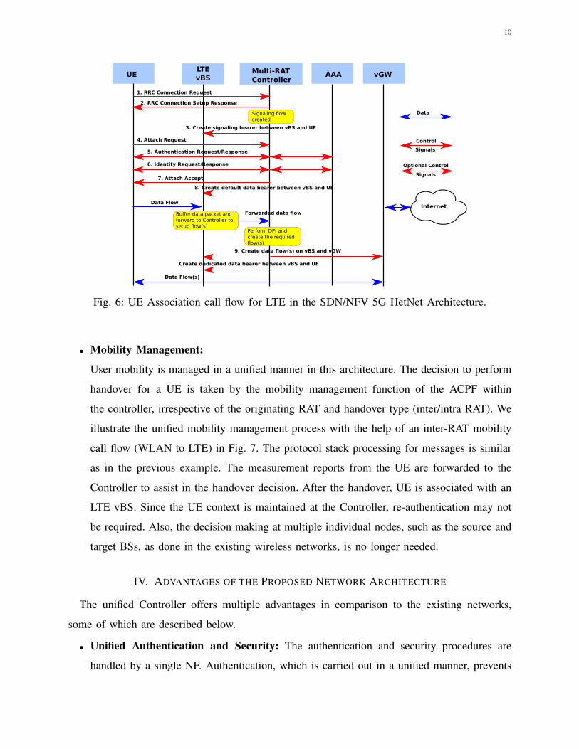
In this section, we present the performance results of an association algorithm for the proposed
architecture in comparison with the existing 4G HetNet association scheme. In existing HetNets,
users inside the WLAN AP coverage area prefer to associate with the AP. However, if the AP
denies association due to overload, a UE may attempt to associate with the LTE eNodeB.
WLAN BS
Multi-RAT Controller
UELTE BS
Fig. 8: LTE-WLAN HetNet Model.
Fig. 8 illustrates the system model which consists of an LTE BS and a WLAN BS with
overlapping coverage areas. We assume that user arrival follows a Poisson process and service
13
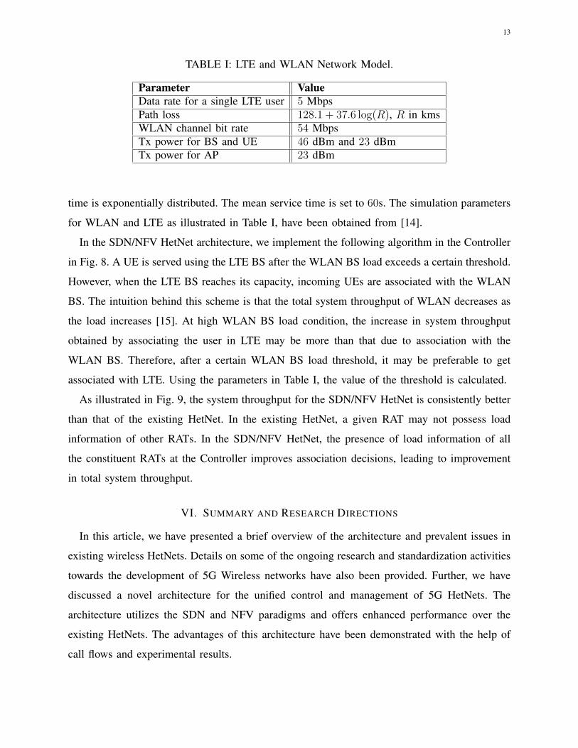
TABLE I: LTE and WLAN Network Model.
Parameter ValueData rate for a single LTE user 5 MbpsPath loss 128.1 + 37.6 log(R), R in kmsWLAN channel bit rate 54 MbpsTx power for BS and UE 46 dBm and 23 dBmTx power for AP 23 dBm
time is exponentially distributed. The mean service time is set to 60s. The simulation parameters
for WLAN and LTE as illustrated in Table I, have been obtained from [14].
In the SDN/NFV HetNet architecture, we implement the following algorithm in the Controller
in Fig. 8. A UE is served using the LTE BS after the WLAN BS load exceeds a certain threshold.
However, when the LTE BS reaches its capacity, incoming UEs are associated with the WLAN
BS. The intuition behind this scheme is that the total system throughput of WLAN decreases as
the load increases [15]. At high WLAN BS load condition, the increase in system throughput
obtained by associating the user in LTE may be more than that due to association with the
WLAN BS. Therefore, after a certain WLAN BS load threshold, it may be preferable to get
associated with LTE. Using the parameters in Table I, the value of the threshold is calculated.
As illustrated in Fig. 9, the system throughput for the SDN/NFV HetNet is consistently better
than that of the existing HetNet. In the existing HetNet, a given RAT may not possess load
information of other RATs. In the SDN/NFV HetNet, the presence of load information of all
the constituent RATs at the Controller improves association decisions, leading to improvement
in total system throughput.
VI. SUMMARY AND RESEARCH DIRECTIONS
In this article, we have presented a brief overview of the architecture and prevalent issues in
existing wireless HetNets. Details on some of the ongoing research and standardization activities
towards the development of 5G Wireless networks have also been provided. Further, we have
discussed a novel architecture for the unified control and management of 5G HetNets. The
architecture utilizes the SDN and NFV paradigms and offers enhanced performance over the
existing HetNets. The advantages of this architecture have been demonstrated with the help of
call flows and experimental results.

14
0.02 0.04 0.06 0.08 0.1 0.12 0.14 0.160
10
20
30
40
50
Arrival Rate (s−1)
System
Through
put(M
bps)
SDN/NFV HetNet AssociationExisting HetNet Association
Fig. 9: System Throughput v/s User Arrival Rates for different Algorithms.
Adopting a unified HetNet architecture opens up multiple avenues for further research. The
SDN/NFV based HetNet architecture utilizes network slicing to meet the desired QoS require-
ments and achieve scalability. Since different slicing strategies are likely to have varying impact
on network Key Performance Indicators (KPIs), strategies for slice creation and slice-to-service
mapping are potential areas for future research. Policies for NF sharing across slices may also
be explored.
Design and standardization of interfaces between different network functions and development
of efficient RRM algorithms are additional areas for research. The SDN/NFV based HetNet
architecture abstracts RAT specific details and provides a common set of parameters to the
applications. The parameter set required to satisfy QoS requirements for various services needs
to be investigated. In conclusion, the article highlights the vast impact that the SDN and NFV
paradigms may have on the design and development of 5G wireless HetNets. While some aspects
of this topic have been explored, there are many more dimensions which hold significant potential
for further study and research.

15
VII. ACKNOWLEDGEMENT
This work is funded by the Department of Electronics and Information Technology (DeitY),
Government of India.
REFERENCES
[1] P. Cerwall, P. Jonsson, and R. Möller, “Ericsson Mobility Report,” Ericsson, Tech. Rep., November 2017. [Online]. Avail-
able: https://www.ericsson.com/assets/local/mobility-report/documents/2017/ericsson-mobility-report-november-2017.pdf.
[2] 3GPP TS 23.261, “Service Requirements for the 5G System,” 2017. [Online]. Available: https://portal.3gpp.org/
desktopmodules/Specifications/SpecificationDetails.aspx?specificationId=3107.
[3] IEEE P1930.1, “Recommended Practice for Software Defined Networking (SDN) based Middleware for Control and
Management of Wireless Networks,” [Online]. Available: https://standards.ieee.org/develop/project/1930.1.html.
[4] E. Haleplidis, K. Pentikousis, S. Denazis, J. H. Salim, D. Meyer, and O. Koufopavlou, “RFC 7426: Software-Defined
Networking (SDN): Layers and Architecture Terminology,” 2015. [Online]. Available: https://tools.ietf.org/html/rfc7426.
[5] ETSI GS 002, “Network Functions Virtualization(NFV) - Architectural Framework,” 2013. [Online]. Available: http:
//www.etsi.org/deliver/etsi_gs/nfv/001_099/002/01.01.01_60/gs_nfv002v010101p.pdf.
[6] M. M. Rahman, C. Despins, and S. Affes, “HetNet Cloud: Leveraging SDN and Cloud Computing for Wireless Access
Virtualization,” in IEEE International Conference Ubiquitous Wireless Broadband (ICUWB), pp. 1–5, 2015.
[7] V. Sagar, R. Chandramouli, and K. Subbalakshmi, “Software Defined Access for Hetnets,” IEEE Communications Magazine,
vol. 54, no. 1, pp. 84–89, 2016.
[8] T. Nguyen-Duc and E. Kamioka, “An Extended SDN Controller for Handover in Heterogeneous Wireless Network,” in
IEEE Asia-Pacific Conference on Communications (APCC), pp. 332–337, 2015.
[9] V. G. Vassilakis, I. D. Moscholios, B. A. Alzahrani, and M. D. Logothetis, “A Software Defined Architecture for Next-
Generation Cellular Networks,” in IEEE International Conference on Communications (ICC), pp. 1–6, 2016.
[10] I. T. Haque and N. Abu-Ghazaleh, “Wireless Software Defined Networking: A Survey and Taxonomy,” IEEE Communi-
cations Surveys and Tutorials, vol. 18, no. 4, pp. 2713–2737, 2016.
[11] E. J. Kitindi, S. Fu, Y. Jia, A. Kabir, and Y. Wang, “Wireless Network Virtualization With SDN and C-RAN for 5G
Networks: Requirements, Opportunities, and Challenges,” IEEE Access, vol. 5, pp. 19099–19115, 2017.
[12] 3GPP TS 23.501, “System Architecture for the 5G System,” 2017. [Online]. Available: https://portal.3gpp.org/
desktopmodules/Specifications/SpecificationDetails.aspx?specificationId=3144.
[13] B. A. A. Nunes, M. Mendonca, X.-N. Nguyen, K. Obraczka, and T. Turletti, “A Survey of Software Defined Networking:
Past, Present, and Future of Programmable Networks,” IEEE Communications Surveys and Tutorials, vol. 16, no. 3,
pp. 1617–1634, 2014.
[14] 3GPP TR 36.839, “Mobility Enhancements in Heterogeneous Networks,” 2012. [Online]. Available: https://portal.3gpp.
org/desktopmodules/Specifications/SpecificationDetails.aspx?specificationId=2540.
[15] G. Bianchi, “Performance Analysis of the IEEE 802.11 Distributed Coordination Function,” IEEE Journal on Selected
Areas in Communications, vol. 18, no. 3, pp. 535–547, 2000.


