
USER’s MANUALBETRIEBSANLEITUNG
08.2008-BSC623-12V_User Manual_080815.doc
DC/DC – ConverterDC/DC - Wandler
BSC623-12V
BRUSA Elektronik AG [email protected] CH - 9466 Sennwald www.brusa.biz

Betriebsanleitung BSC623-12V User’s manual BSC623-12V
Inhaltsverzeichnis Table of contents
1 Vor der Inbetriebnahme Before operation............................................................... 3
2 Sicherheitsmassnahmen For safe use of this unit ................................................... 4
3 Lieferumfang Scope of delivery ............................................................... 6
4 Spezifikationen Specifications .................................................................... 7 4.1 Übersicht Overview ................................................................................ 7 4.2 Einführung Introduction ............................................................................ 8 4.3 Terminologie Terminology ............................................................................ 8 4.4 Elektrische Eckdaten Electrical parameters ............................................................. 8 4.5 Mechanische Eckdaten Mechanical parameters........................................................ 10 4.6 Blockschaltbild Block diagram...................................................................... 10 5 Schnittstellen Interfaces......................................................................... 11 5.1 Leistungsanschlüsse Power connectors ................................................................ 11 5.2 Steueranschluss Control interface .................................................................. 12 6 Technische Eigenschaften Technical characteristics................................................ 20 6.1 Interne Stromversorgungen Internal power supplies ....................................................... 20 6.2 Zuverlässigkeit Reliabilty .............................................................................. 22 6.3 EMV – Betrachtungen EMC – considerations ......................................................... 26 7 Inbetriebnahme des Gerätes Start-up the device .......................................................... 31 7.1 Befestigung des Geräts im Fahrzeug Mounting of the device in the vehicle .................................. 31 7.2 Anschluss des Gerätes Connecting the device......................................................... 32 7.3 Bedienung des Gerätes Operation of the device ....................................................... 33 7.4 Programmieren der Firmware Download the firmware ....................................................... 33 8 Garantie Warranty .......................................................................... 41
08.2008-BSC623-12V_User Manual_080815.doc 2 / 41

Betriebsanleitung BSC623-12V User’s manual BSC623-12V
1 Vor der Inbetriebnahme Before operation
Geschätzter Kunde! Mit dem BRUSA DC/DC-Wandler BSC623-12V haben Sie ein sehr leistungsfähiges und vielseitiges Gerät er-worben. Um dessen Vorzüge zu nutzen und jegliche Gefahr für Mensch und Material zu vermeiden, lesen Sie bitte vor der Inbetriebnahme diese Anleitung sorg-fältig durch. Wir empfehlen Ihnen die Anleitung für spä-teres Nachschlagen aufzubewahren. Änderungen an der Betriebsanleitung sind vorbehalten und werden nicht angekündigt. Holen Sie sich bitte die aktuelle Version von unserer Homepage: www.brusa.biz.
Dear Customer! With the BRUSA DC/DC-Converter BSC623-12V you purchased a powerful and versatile product. To take advantage of its features and to avoid danger for man and material please read the operating instructions carefully before operating the unit. We recommend to keep the user’s manual for later reference. Changes to the user’s manual are subject to further de-velopment of the device and won’t be announced. Please download the latest version of this manual on: www.brusa.biz.
08.2008-BSC623-12V_User Manual_080815.doc 3 / 41
Betriebsanleitung BSC623-12V User’s manual BSC623-12V
2 Sicherheitsmassnahmen For safe use of this unit
Zu Ihrer Sicherheit For your safety
• Lesen Sie die Anleitung gründlich. • Read the manual carefully.
• Bitte beachten Sie, dass sorgloser Umgang mit hö-heren Gleichspannungen zu sehr gefährlichen und lebensbedrohenden Situationen führen kann.
• Please note that careless handling of high DC volt-ages can be very dangerous and lethal.
• Das Gerät produziert Abwärme. Unvorsichtige Be-rührung kann zu Verbrennungen führen. Bitte keine leicht entzündbaren Gegenstände in der Nähe des Gerätes montieren.
• This unit produces waste heat. Touching the hot unit can lead to injuries and burnings. Please do not install easy flammable material close to the unit.
08.2008-BSC623-12V_User Manual_080815.doc 4 / 41

Betriebsanleitung BSC623-12V User’s manual BSC623-12V
Zu Ihrer Sicherheit • Lassen Sie das Gerät durch einen Fachmann im
Fahrzeug installieren und in Betrieb nehmen. • Öffnen Sie keinesfalls das Gerät ohne vorherige
Rücksprache mit dem Werk. • Stecken Sie niemals die Hochspannungsstecker ein
ohne vorher sicherzustellen, dass am Stecker keine Hochspannung anliegt (z.B.: im Fahrzeug durch Schütze).
• Trennen Sie niemals die Hochspannungsstecker vom Gerät ohne vorher sicherzustellen, dass keine Hochspannung mehr anliegt.
• Verwenden Sie einen Isolationswächter für die Ü-berwachung der galvanischen Trennung zwischen Hoch- und Niederspannungskreis.
For your safety • Have the unit installed and made operational by a
skilled professional. • Do not open the unit without contacting the manu-
facturer before. • Do not connect the high voltage connectors before
being sure that there is no high voltage on the con-nector itself (e.g.: in a vehicle by contactors).
• Never disconnect the high voltage connectors be-fore being sure that there is no high voltage on the DC-link anymore.
• Use an isolation failure detector in order to monitor the galvanic isolation between the high and the low voltage DC-link.
Um einen Schaden am Gerät zu vermeiden • Sorgen Sie für ausreichende Kühlung des Gerätes.
Eine niedrige Kühlwassertemperatur kann die Le-bensdauer beträchtlich erhöhen.
• Vermeiden Sie den Betrieb nahe an Wärmequellen oder in direkter Sonnenstrahlung.
• Trotz des hohen IP-Schutzes empfehlen wir, das Gerät soweit als möglich von Umwelteinflüssen wie Regen oder Spritzwasser zu schützen.
To prevent from damage of the device • Ensure sufficient cooling of the device. A low tem-
perature of the cooling water has a considerable positive effect on the lifetime.
• Avoid operation of the device next to a heat source or in direct sunlight.
• Even though the high IP-protection we recommend to not expose the unit to rain or splash water.
08.2008-BSC623-12V_User Manual_080815.doc 5 / 41

Betriebsanleitung BSC623-12V User’s manual BSC623-12V
3 Lieferumfang Scope of delivery
Für einen betriebsbereiten DC/DC-Wandler sind folgende Teile notwendig:
A complete set to run the DC/DC-converter:
• DC/DC-Wandler BSC623-12V
• DC/DC-converter BSC623-12V
• Harting Hochspannungssteckverbindung kunden-seitig HAN-Modular Compact: Tüllengehäuse gerade HAN-Modular Compact Trägergehäuse HAN-Modular Compact Buchseneinsatz HAN CC 4mm2 Krimpkontaktbuchsen Kabelverschraubung HSK-M-EMV M25x1.5 für
Kabeldurchmesser 9-16mm
• Harting High voltage connector customer side HAN-Modular Compact: Hood top entry HAN-Modular Compact Carrier hood HAN-Modular Compact Socket module HAN CC 4mm2 crimp contact plug sockets Cable gland HSK-M-EMV M25x1.5 for cable
diameter 9-16mm • Niederspannungssteckverbindung kundenseitig:
Pluspolsteckergehäuse für 50mm2-Kabel MC-Kontakt SP10AR-N/50 O-Ring M3x5 Gewindestift M8/50mm2 gerader Kabelschuh für 12V-
Minusanschluss M8/50mm2 abgewinkelter Kabelschuh für 12V-
Minusanschluss
• Low voltage connectors customer side: Plus pole connector housing for 50mm2-cable MC-contact SP10AR-N/50 O-ring seal M3x5 set screw M8/50mm2 straight cable shoe for 12V-minus
connection M8/50mm2 right angle cable shoe for 12V-
minus connection
• 23-poliger Steuerstecker mit Krimpkontakten: AMPSEAL Buchse: 770680-1 AMPSEAL Kontakte: 770854-1 Drahtdurchmesser: 0.5mm2
• 23-pole control connector with crimp contacts: AMPSEAL socket: 770680-1 AMPSEAL contacts: 770854-1 Wire size: 0.5mm2
08.2008-BSC623-12V_User Manual_080815.doc 6 / 41

Betriebsanleitung BSC623-12V User’s manual BSC623-12V
4 Spezifikationen Specifications
4.1 Übersicht Overview
Wasseranschlüsse Cooling pipes
Befestigungslöcher Mounting holes
LV-Minuspol LV-Minus pole
Druckausgleichs - Membran Pressure balance membrane
LV-Pluspol Leistungstecker LV-Plus pole power connector
HV-Leistungstecker HV-power connector
Steuerstecker Control connector
08.2008-BSC623-12V_User Manual_080815.doc 7 / 41
Betriebsanleitung BSC623-12V User’s manual BSC623-12V
4.2 Einführung Introduction
Der BSC623-12V ist ein bidirektionaler DC/DC-Wandler mit galvanischer Trennung zwischen dem Hochspan-nungs- und Niederspannungskreis. Das Gerät basiert zum einen auf einer serien-resonant arbeitenden Trafo-stufe, durch welche die galvanische Trennung realisiert wird. Zum anderen kann durch zwei zur Rippelreduzie-rung verzahnt arbeitende Hochsetz-/Tiefsetzsteller die gewünschte Spannung im jeweiligen Betriebsmodus eingestellt werden. Aufgrund der resonanten Topologie der Trafostufe und der sogenannten Autokommutierung des Hochsetz-/Tiefsetzstellers werden nicht nur Verlus-te auf ein Minimum begrenzt, sondern auch hervorra-gende EMV-Eigenschaften erreicht.
The BSC623-12V is a bidirectional DC/DC-Converter with galvanic isolation between the high voltage and low voltage circuit. The device is based on one hand upon a series-resonant operating transformer stage, which ensures the galvanic isolation. On the other hand two buck/boost-converters, that are operated inter-leaved in order to reduce ripple currents, allow to adjust the required voltage level in the corresponding opera-tion mode. Due to the resonant topology of the trans-former stage and the so-called Autocommutation of the buck/boost-converter not only losses are reduced to a minimum but also an excellent EMC-behavior is ob-tained.
4.3 Terminologie Terminology
• Hochspannung, Leistungsanschluss (HV): Fuel Cell Circuit (FCC), Battery Circuit (BC)
• Niederspannung, Leistungsanschluss (LV): Bordnetz (AUX)
• Niederspannung, Steueranschluss (LV): Bordnetz (AUX)
• High voltage, Power interface (HV): Fuel cell circuit (FCC), Battery circuit (BC)
• Low voltage, Power interface (HV): Auxiliary supply (AUX)
• Low voltage, Control interface (LV): Auxiliary supply (AUX)
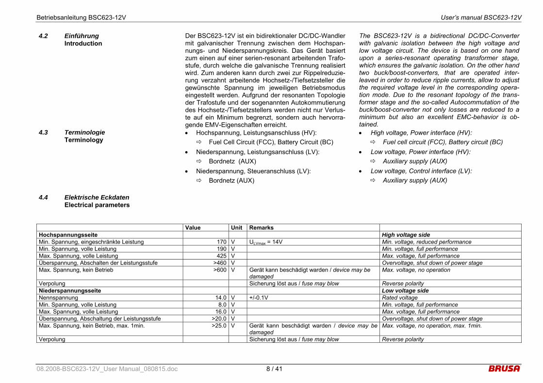
4.4 Elektrische Eckdaten Electrical parameters
Value Unit Remarks Hochspannungsseite High voltage side Min. Spannung, eingeschränkte Leistung 170 V ULVmax = 14V Min. voltage, reduced performance Min. Spannung, volle Leistung 190 V Min. voltage, full performance Max. Spannung, volle Leistung 425 V Max. voltage, full performance Überspannung, Abschalten der Leistungsstufe >460 V Overvoltage, shut down of power stage Max. Spannung, kein Betrieb >600 V Gerät kann beschädigt warden / device may be
damaged Max. voltage, no operation
Verpolung Sicherung löst aus / fuse may blow Reverse polarity Niederspannungsseite Low voltage side Nennspannung 14.0 V +/-0.1V Rated voltage Min. Spannung, volle Leistung 8.0 V Min. voltage, full performance Max. Spannung, volle Leistung 16.0 V Max. voltage, full performance Überspannung, Abschaltung der Leistungsstufe >20.0 V Overvoltage, shut down of power stage Max. Spannung, kein Betrieb, max. 1min. >25.0 V Gerät kann beschädigt warden / device may be
damaged Max. voltage, no operation, max. 1min.
Verpolung Sicherung löst aus / fuse may blow Reverse polarity
08.2008-BSC623-12V_User Manual_080815.doc 8 / 41
Betriebsanleitung BSC623-12V User’s manual BSC623-12V
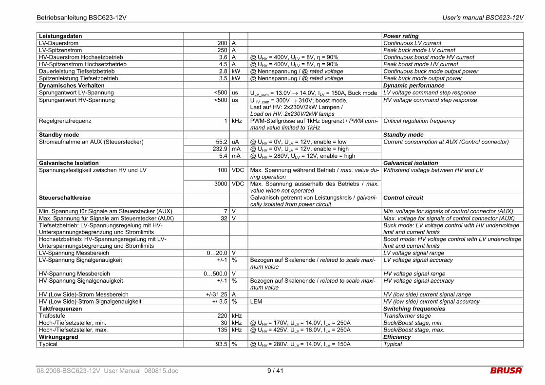
Leistungsdaten Power rating LV-Dauerstrom 200 A Continuous LV current LV-Spitzenstrom 250 A Peak buck mode LV current HV-Dauerstrom Hochsetzbetrieb 3.6 A @ UHV = 400V, ULV = 8V, η = 90% Continuous boost mode HV current HV-Spitzenstrom Hochsetzbetrieb 4.5 A @ UHV = 400V, ULV = 8V, η = 90% Peak boost mode HV current Dauerleistung Tiefsetzbetrieb 2.8 kW @ Nennspannung / @ rated voltage Continuous buck mode output power Spitzenleistung Tiefsetzbetrieb 3.5 kW @ Nennspannung / @ rated voltage Peak buck mode output power Dynamisches Verhalten Dynamic performance Sprungantwort LV-Spannung <500 us ULV_com = 13.0V → 14.0V, ILV = 150A, Buck mode LV voltage command step response Sprungantwort HV-Spannung <500 us UHV_com = 300V → 310V; boost mode,
Last auf HV: 2x230V/2kW Lampen / Load on HV: 2x230V/2kW lamps
HV voltage command step response
Regelgrenzfrequenz 1 kHz PWM-Stellgrösse auf 1kHz begrenzt / PWM com-mand value limited to 1kHz
Critical regulation frequency
Standby mode Standby mode 55.2 uA @ UHV = 0V, ULV = 12V, enable = low
232.9 mA @ UHV = 0V, ULV = 12V, enable = high Stromaufnahme an AUX (Steuerstecker)
5.4 mA @ UHV = 280V, ULV = 12V, enable = high
Current consumption at AUX (Control connector)
Galvanische Isolation Galvanical isolation 100 VDC Max. Spannung während Betrieb / max. value du-
ring operation Spannungsfestigkeit zwischen HV und LV
3000 VDC Max. Spannung ausserhalb des Betriebs / max. value when not operated
Withstand voltage between HV and LV
Steuerschaltkreise Galvanisch getrennt von Leistungskreis / galvani-cally isolated from power circuit
Control circuit
Min. Spannung für Signale am Steuerstecker (AUX) 7 V Min. voltage for signals of control connector (AUX) Max. Spannung für Signale am Steuerstecker (AUX) 32 V Max. voltage for signals of control connector (AUX) Tiefsetzbetrieb: LV-Spannungsregelung mit HV-Unterspannungsbegrenzung und Stromlimits
Buck mode: LV voltage control with HV undervoltage limit and current limits
Hochsetzbetrieb: HV-Spannungsregelung mit LV-Unterspannungsbegrenzung und Stromlimits
Boost mode: HV voltage control with LV undervoltage limit and current limits
LV-Spannung Messbereich 0…20.0 V LV voltage signal range LV-Spannung Signalgenauigkeit +/-1 % Bezogen auf Skalenende / related to scale maxi-
mum value LV voltage signal accuracy
HV-Spannung Messbereich 0…500.0 V HV voltage signal range HV-Spannung Signalgenauigkeit +/-1 % Bezogen auf Skalenende / related to scale maxi-
mum value HV voltage signal accuracy
HV (Low Side)-Strom Messbereich +/-31.25 A HV (low side) current signal range HV (Low Side)-Strom Signalgenauigkeit +/-3.5 % LEM HV (low side) current signal accuracy Taktfrequenzen Switching frequencies Trafostufe 220 kHz Transformer stage Hoch-/Tiefsetzsteller, min. 30 kHz @ UHV = 170V, ULV = 14.0V, ILV = 250A Buck/Boost stage, min. Hoch-/Tiefsetzsteller, max. 135 kHz @ UHV = 425V, ULV = 16.0V, ILV = 250A Buck/Boost stage, max. Wirkungsgrad Efficiency Typical 93.5 % @ UHV = 280V, ULV = 14.0V, ILV = 150A Typical
08.2008-BSC623-12V_User Manual_080815.doc 9 / 41

Betriebsanleitung BSC623-12V User’s manual BSC623-12V
4.5 Mechanische Eckdaten Mechanical parameters
Kühlung Thermal Kühlmedium 50% Water, 50% Ethylenglycol Coolant medium Kühlmittelvolumen 225 ml Inklusive Anschlussstutzen / Including nozzle Coolant volume Min. Kühlmitteltemperatur -40 °C Min. coolant temperature Max. Kühlmitteltemperatur 65 °C Max. coolant temperature Durchflussrate >4 l/min Cooling flow rate Druckabfall <0.1 bar @ 4l/min Pressure loss Max. statischer Druck 2 bar Max. static pressure Umgebungstemperaturbereich (Lagerung) -40...105 °C Ambient temperature range (storing) Umgebungstemperaturbereich (Betrieb) -40….85 °C Ambient temperature range (operating) Mechanik Mechanical Material AlMgSi1 Korrosionsfestes Aluminium / Corrosion-resistant
aluminum Material
Länge 300 mm Length Breite 150 mm Width Höhe 70 mm Height Volumen 3.15 l Ohne Stecker / without connectors Volume Gewicht 4.7 kg Weight IP-Schutz IP65 IP-protection Wasserdichte Druckausgleichsmembran Integriert / Integrated Waterresistent pressure balance
4.6 Blockschaltbild
Block diagram
Resonant galvanically isolated bidirectional DC/DC -converter with constant voltage ratio 10:1
AC DC
DC AC
Low Voltage 8…16VDC max. 250A
Max. voltage loss: +/-0,5V
Low voltage
filter
High voltage 170…425VDC max. 21A
Resonant bidirectionalbuck/boost - converter
with variable voltageratio 0,18…0,87
75…165VDC max. 25A
High
voltage filter
10 : 1
08.2008-BSC623-12V_User Manual_080815.doc 10 / 41
Betriebsanleitung BSC623-12V User’s manual BSC623-12V
5 Schnittstellen Interfaces
5.1 Leistungsanschlüsse Power connectors
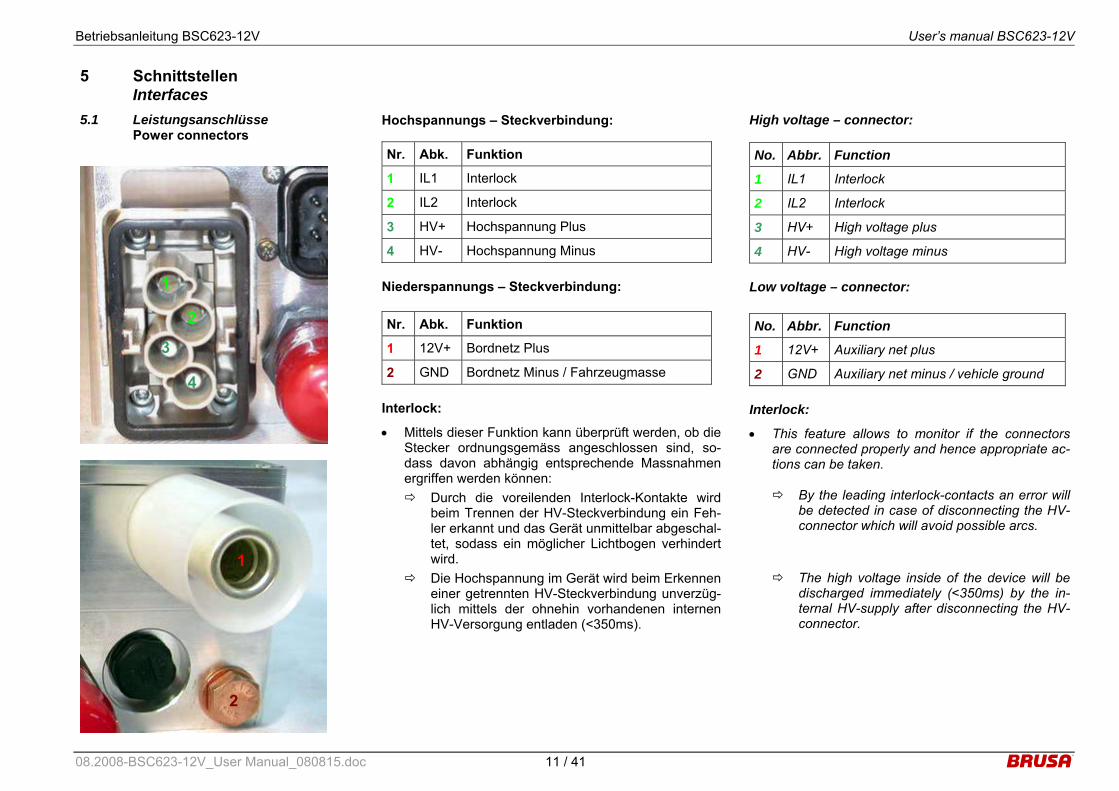
Hochspannungs – Steckverbindung:
Niederspannungs – Steckverbindung:
Interlock:
• Mittels dieser Funktion kann überprüft werden, ob die Stecker ordnungsgemäss angeschlossen sind, so-dass davon abhängig entsprechende Massnahmen ergriffen werden können: Durch die voreilenden Interlock-Kontakte wird
beim Trennen der HV-Steckverbindung ein Feh-ler erkannt und das Gerät unmittelbar abgeschal-tet, sodass ein möglicher Lichtbogen verhindert wird.
Die Hochspannung im Gerät wird beim Erkennen einer getrennten HV-Steckverbindung unverzüg-lich mittels der ohnehin vorhandenen internen HV-Versorgung entladen (<350ms).
Nr. Abk. Funktion
1 IL1 Interlock
2 IL2 Interlock
3 HV+ Hochspannung Plus
4 HV- Hochspannung Minus
Nr. Abk. Funktion
1 12V+ Bordnetz Plus
2 GND Bordnetz Minus / Fahrzeugmasse
High voltage – connector:
Low voltage – connector:
Interlock:
• This feature allows to monitor if the connectors are connected properly and hence appropriate ac-tions can be taken.
By the leading interlock-contacts an error will be detected in case of disconnecting the HV-connector which will avoid possible arcs.
The high voltage inside of the device will be
discharged immediately (<350ms) by the in-ternal HV-supply after disconnecting the HV-connector.
No. Abbr. Function
1 IL1 Interlock
2 IL2 Interlock
3 HV+ High voltage plus
4 HV- High voltage minus
No. Abbr. Function
1 12V+ Auxiliary net plus
2 GND Auxiliary net minus / vehicle ground
1
2
3
4
1
2
08.2008-BSC623-12V_User Manual_080815.doc 11 / 41
Betriebsanleitung BSC623-12V User’s manual BSC623-12V
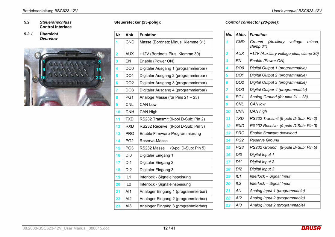
5.2 Steueranschluss Control interface
5.2.1 Übersicht Overview
Steuerstecker (23-polig):
Nr. Abk. Funktion
1 GND Masse (Bordnetz Minus, Klemme 31)
2 AUX +12V (Bordnetz Plus, Klemme 30)
3 EN Enable (Power ON)
4 DO0 Digitaler Ausgang 1 (programmierbar)
5 DO1 Digitaler Ausgang 2 (programmierbar)
6 DO2 Digitaler Ausgang 3 (programmierbar)
7 DO3 Digitaler Ausgang 4 (programmierbar)
8 PG1 Analoge Masse (für Pins 21 – 23)
9 CNL CAN Low
10 CNH CAN High
11 TXD RS232 Transmit (9-pol D-Sub: Pin 2)
12 RXD RS232 Receive (9-pol D-Sub: Pin 3)
13 PRO Enable Firmware-Programmierung
14 PG2 Reserve-Masse
15 PG3 RS232 Masse (9-pol D-Sub: Pin 5)
16 DI0 Digitaler Eingang 1
17 DI1 Digitaler Eingang 2
18 DI2 Digitaler Eingang 3
19 IL1 Interlock - Signaleinspeisung
20 IL2 Interlock - Signaleinspeisung
21 AI1 Analoger Eingang 1 (programmierbar)
22 AI2 Analoger Eingang 2 (programmierbar)
23 AI3 Analoger Eingang 3 (programmierbar)
Control connector (23-pole):
No. Abbr. Function
1 GND Ground (Auxiliary voltage minus, clamp 31)
2 AUX +12V (Auxiliary voltage plus, clamp 30)
3 EN Enable (Power ON)
4 DO0 Digital Output 1 (programmable)
5 DO1 Digital Output 2 (programmable)
6 DO2 Digital Output 3 (programmable)
7 DO3 Digital Outpur 4 (programmable)
8 PG1 Analog Ground (for pins 21 – 23)
9 CNL CAN low
10 CNH CAN high
11 TXD RS232 Transmit (9-pole D-Sub: Pin 2)
12 RXD RS232 Receive (9-pole D-Sub: Pin 3)
13 PRO Enable firmware download
14 PG2 Reserve Ground
15 PG3 RS232 Ground (9-pole D-Sub: Pin 5)
16 DI0 Digital Input 1
17 DI1 Digital Input 2
18 DI2 Digital Input 3
19 IL1 Interlock – Signal Input
20 IL2 Interlock – Signal Input
21 AI1 Analog Input 1 (programmable)
22 AI2 Analog Input 2 (programmable)
23 AI3 Analog Input 2 (programmable)
1 89 15
16 23
08.2008-BSC623-12V_User Manual_080815.doc 12 / 41
Betriebsanleitung BSC623-12V User’s manual BSC623-12V
5.2.2 Beschreibung der einzelnen Steuersteckerpins Description of the control connector pins
5.2.2.1 GND (Masse, Ground), Pin 1 Interne Beschaltung Internal Circuit
1MΩ
23.5
µF GND (1)
Gehäuse/housing
• Direkte Verbindung zur Masse der Steuereinheit. • Die Signalmasse ist nur kapazitiv mit dem Gehäuse
verbunden, d.h. die Signalmasse ist von der Leis-tungsmasse (Gehäuse) galvanisch getrennt, um Masseschleifen zu vermeiden.
• Bei Verdrahtung von BSC623-12V-Steuersignalen mit anderen Fahrzeug-Komponenten (z.B. Fahran-trieb, Bordbatterie, Batteriemanagement, Brennstoff-zelle) muss hier die Fahrzeug-Masse angeschlossen werden.
• Direct connection to control unit ground . • The signal ground is only coupled capacitively to
the housing, which means the signal ground is galvanically isolated from the power ground (hous-ing), in order to avoid ground loops.
• If BSC623-12V control signals are connected to other vehicle components (e.g. propulsion system, on-board battery, battery management system, fuel cell) the vehicle’s ground must be connected to this terminal.
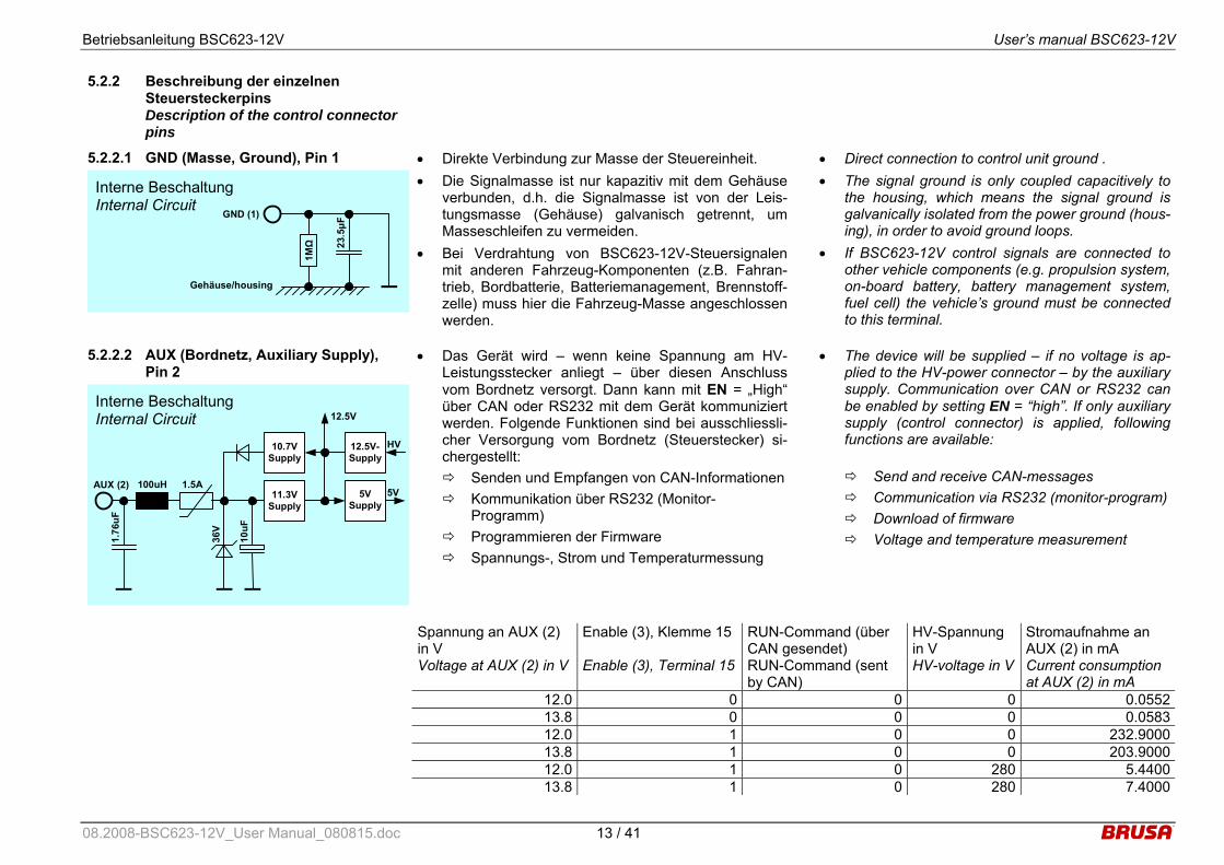
5.2.2.2 AUX (Bordnetz, Auxiliary Supply), Pin 2
Interne Beschaltung Internal Circuit
1.76
uF
AUX (2) 100uH 1.5A 5V
36V
5V Supply
12.5V
10uF
12.5V-Supply
HV
11.3V Supply
10.7V Supply
• Das Gerät wird – wenn keine Spannung am HV-Leistungsstecker anliegt – über diesen Anschluss vom Bordnetz versorgt. Dann kann mit EN = „High“ über CAN oder RS232 mit dem Gerät kommuniziert werden. Folgende Funktionen sind bei ausschliessli-cher Versorgung vom Bordnetz (Steuerstecker) si-chergestellt: Senden und Empfangen von CAN-Informationen Kommunikation über RS232 (Monitor-
Programm) Programmieren der Firmware Spannungs-, Strom und Temperaturmessung
• The device will be supplied – if no voltage is ap-plied to the HV-power connector – by the auxiliary supply. Communication over CAN or RS232 can be enabled by setting EN = “high”. If only auxiliary supply (control connector) is applied, following functions are available:
Send and receive CAN-messages Communication via RS232 (monitor-program) Download of firmware Voltage and temperature measurement
Spannung an AUX (2) in V
Enable (3), Klemme 15 RUN-Command (über CAN gesendet)
HV-Spannung in V
Stromaufnahme an AUX (2) in mA
Voltage at AUX (2) in V Enable (3), Terminal 15 RUN-Command (sent by CAN)
HV-voltage in V Current consumption at AUX (2) in mA
12.0 0 0 0 0.0552 13.8 0 0 0 0.0583 12.0 1 0 0 232.9000 13.8 1 0 0 203.9000 12.0 1 0 280 5.4400 13.8 1 0 280 7.4000
08.2008-BSC623-12V_User Manual_080815.doc 13 / 41

Betriebsanleitung BSC623-12V User’s manual BSC623-12V
5.2.2.3 EN (Enable, Power ON), Pin 3 Interne Beschaltung Internal Circuit
47nF
EN (3)
5V 2.
7kΩ
220p
F 1,0V
3,3V
Schmitt Trigger 12
0kΩ
5V Supply Enable
23.5
kΩ
2.7kΩ
5V Supply
11.3V Supply
10n0
F
100n
F
11.3V SupplyEnable
22kΩ
33V
• Bei Anlegen einer Spannung an AUX und mit EN = „High“ (+7V...32V) wird das Gerät in den betriebsbe-reiten Modus versetzt. Sinnvollerweise erfolgt dies durch eine Verbindung des Enable-Pins über einen Schalter mit dem Bordnetz.
• Um eine neue Firmware zu programmieren, ist es nicht erforderlich, dass EN = „High“ ist.
• Auch wenn am HV-Stecker Hochspannung anliegt, wird die geräteinterne Logik nur dann versorgt, wenn der Pin EN = „High“ ist (oder Pin PROG = „High“ ist).
• By applying a voltage to AUX and by setting EN = „high“ (+7V...32V) the device will be ready to op-erate. Reasonably this is realized by using a switch in order to connect the enable-pin to the auxiliary supply.
• In order to download a new firmware, EN does not have to be „high”.
• Even when high voltage is applied to the HV-connector, the device internal logic is only sup-plied, if the pin EN = „high“ (or pin PROG = “high”).
08.2008-BSC623-12V_User Manual_080815.doc 14 / 41

Betriebsanleitung BSC623-12V User’s manual BSC623-12V
5.2.2.4 DO0 – DO3 (Digitale Ausgänge, Digi-tal Outputs), Pins 3 - 7
Interne Beschaltung Internal Circuit
10nF
DO0 - DO3 (4 - 7)
AUX
500Ω
33
V
• Mit diesen vier programmierbaren digitalen Ausgän-gen können niederfrequente Anwendungen realisiert werden: Ansteuerung von LEDs für Statusfunktionen
(z.B. Unter- bzw. Überspannung, Überschreitung einer Stromgrenze, Temperatur-Derating,...).
Ansteuerung von anderen externen Komponen-ten (PWM für Anzeigeinstrumente, Relais, kleine Lüfter,...).
• Alle vier digitalen Ausgänge weisen folgende Merk-male auf: RDSON = 1,7Ω bei TA = 25°C VOUTmax = 32V VCLAMP ≥ 45V (Spannungsfestigkeit für induktive
Lasten) Kurzschlussfestigkeit (Imax = 700mA). Abschaltung bei zu hoher Temperatur aufgrund
von Überbelastung. • Bei Auftreten eines Fehlers an einem Ausgang sind
die restlichen Ausgänge weiter funktionstauglich, wenn es durch den einen Fehler nicht zu einer Ab-schaltung bei den restlichen Ausgängen aufgrund zu hoher Temperatur führt.
• Die Ausgänge können mit Frequenzen bis zu 10kHz betrieben werden. Um auch bei diesen Frequenzen noch ordentliche Signalverläufe zu ermöglichen, ist jeder Ausgang mit einem 500Ω/2W Pullup-Widerstand beschaltet.
• With these four programmable digital outputs low frequency applications can be realized:
Drive LEDs for status functions (e.g.: under- or overvoltage, exceeding of current limit, temperature derating,...).
Drive other external components (PWM for display instruments, relays, small fans,...).
• All four digital outputs show the following features:
RDSON = 1,7Ω at TA = 25°C VOUTmax = 32V VCLAMP ≥ 45V (clamping voltage for inductive
loads) Short circuit detection (Imax = 700mA). Over-temperature shutdown due to overload.
• In case of such a failure at one of the outputs the other outputs remain still fully functional as long as such a failure does not lead to over-temperature shut down of the other outputs.
• All outputs can be driven with a frequency up to 10kHz. In order to ensure proper signals even such frequencies, each output has a 500Ω/2W pull-up resistor.
08.2008-BSC623-12V_User Manual_080815.doc 15 / 41

Betriebsanleitung BSC623-12V User’s manual BSC623-12V
5.2.2.5 PG1 – PG3 (Analoge Masse, Analog Ground), Pins 8, 14, 15
Interne Beschaltung Internal Circuit
4.7µ
F
PG1 – PG3 (8, 14, 15)
300m
A
• Zur Vereinfachung der externen Verdrahtung stehen drei zusätzliche Masse-Anschlüsse zur Verfügung. Diese sind über je eine PTC-Sicherung mit der Ver-sorgungs-Masse GND verbunden.
• Folgende Zuordnung wird vorgeschlagen: Nr. Abk. Funktion
8 PG1 Analoge Masse (für Pins 21 - 23)
14 PG2 Reserve Masse
15 PG3 RS232 - Masse (9-pol D-Sub: Pin 5)
• In order to simplify external wiring, three additional ground pins are available. Each pin is connected to the supply’s ground GND by a ptc-fuse.
• Following pin assignment is suggested: Nr. Abbr. Function
8 PG1 Analog Ground (for pins 21 - 23)
14 PG2 Reserve Ground
15 PG3 RS232 Ground (9-pol D-Sub: Pin 5)
5.2.2.6 CNH, CNL (CAN-Bus, CAN-Interface), Pins 9, 10
Interne Beschaltung Internal Circuit
47pF
CNL (9)
33V
51uH
47pF
CNH (10)
120Ω
33V
51uH
Termination resistor is optional
CAN-Transceiver and galvanic
isolation
Die CAN-Schnittstelle weist folgende Eigenschaften auf:
• CAN 2.0 B, 500 kBit (optional 1Mbit) • Die CAN-Schnittstelle weist eine Potentialtrennung
von der Masse und den übrigen Steuersignalen auf, um Störungen durch Potentialverschiebungen zu vermeiden.
• Der 120Ω Abschlusswiderstand kann optional be-stückt werden.
• Über die CAN-Schnittstelle können Informationen gemäss der vom Kunden festgelegten CAN-Matrix gesendet und empfangen werden.
The CAN interface has following characteristics: • CAN 2.0 B, 500 kBit (optional 1Mbit) • Galvanic isolation from ground and all other con-
trol signals in order to avoid interferences caused by ground offset voltages.
• The 120Ω termination resistor can be mounted optionally.
• The CAN interface allows to transmit and receive messages according to the CAN-matrix defined by the customer.
08.2008-BSC623-12V_User Manual_080815.doc 16 / 41

Betriebsanleitung BSC623-12V User’s manual BSC623-12V
5.2.2.7 TXD, RXD (RS232-Schnittstelle, RS232-Interface), Pins 11, 12
Interne Beschaltung Internal Circuit
470p
F
RXD (12)
10V
470p
F
TXD (11)
15V
RS232-Transceiver
200Ω
200Ω
470p
F
470p
F
100Ω
100Ω
33V
33V
• Das RS232-Interface ermöglicht eine direkte serielle Verbindung zwischen dem BSC623-12V und einem Computer. Die dafür notwendige Software kann von der Homepage www.brusa.biz heruntergeladen wer-den. Folgende Funktionen werden unterstützt: Anzeige der Momentanwerte von Strom, Span-
nung, Leistung und Temperatur(Monitorprogramm).
Programmieren der von BRUSA mitgelieferten oder nachgereichten Firmware (durch Setzen von PRO = „High“). Für weitere Informationen zum Programmieren kontaktieren Sie bitte direkt BRUSA.
Belegung der 9-poligen D-Sub Kabelbuchse:
RXD (12)
TXD (11)
9-polige D-Sub Kabelbuchse
PG3 (15) 5
23
• The RS232 interface provides a direct serial con-nection between the BSC623-12V and a com-puter. The necessary software can be downloaded from our homepage www.brusa.biz. Following functions are provided: Display the actual current, voltage, power and
temperature values (monitor program).
Download the firmware provided by BRUSA (by setting PRO = “high”). For further informa-tion regarding the download please contact directly BRUSA.
Pin assignment of the 9-pole D-sub socket:
RXD (12)
TXD (11)
9 pin D-Sub connector, female
PG3 (15) 5
23
5.2.2.8 PRO (Enable Firmware-
Programmierung, Enable firmware download), Pin 13
Interne Beschaltung Internal Circuit
47nF
PRO (13)
5V
2.7kΩ
220p
F
1,0V
3,3V
Schmitt Trigger 12
0kΩ
5V Supply Enable
23.5
kΩ
2.7kΩ
5V Supply
11.3V Supply
10n0
F
100n
F
11.3V SupplyEnable
22kΩ
33V
• Dieser Anschluss wird ausschliesslich für das Pro-grammieren einer neuen Firmware aktiviert (PRO = „High“), wobei dann EN nicht „High“ sein muss.
• Sowohl bei Versorgung von HV als auch vom Bord-netz löst PRO = „High“ folgende Vorgänge aus:
Falls das Gerät im Betrieb ist, wird dieser ge-stoppt.
Das Gerät ist dann empfangsbereit und kann über die serielle Schnittstelle programmiert wer-den.
• Das Programmieren einer neuen Firmware darf nur in Absprache mit BRUSA durchgeführt werden. Die Firmware wird dann allenfalls per Email zur zuge-stellt.
• This pin is exclusively activated (PRO = „high“) to download a new firmware, whereas EN does not have to be „high”.
• PRO = „high” causes the following actions regard-less of supplying the device from HV or auxiliary supply: If the device is in operation, it will be shut
down. The device is then ready to be programmed
via the serial interface.
• The download of a new firmware may only be done with agreement of BRUSA. A new firmware can be provided by email then.
08.2008-BSC623-12V_User Manual_080815.doc 17 / 41

Betriebsanleitung BSC623-12V User’s manual BSC623-12V
5.2.2.9 DI0 – DI2 (Digitale Eingänge, Digital Inputs), Pins 16 – 18
Interne Beschaltung Internal Circuit
10nF
DI0 – DI2 (16 - 18)
5V
220p
F
1,0V
3,3V
Schmitt Trigger
22kΩ 23
.5kΩ
uC33
V
• Mit diesen drei Eingängen können verschiedene Funktionen realisiert werden wie folgender Vorschlag zeigt: DI0: Hochsetzbetrieb DI1: Tiefsetzbetrieb DI2: Spannungs- oder Stromregelmodus
• With these three inputs various functions can be realized as the following proposal shows:
DI0: Boost mode DI1: Buck mode DI2: Voltage or current regulation mode
5.2.2.10 IL1, IL2 (Interlock), Pins 19, 20 Interne Beschaltung Internal Circuit
10nF
IL1 (19)
IL2 (20)
IL1 (1)
IL2 (2)
High voltage power connector
12mH
12mH
10nF
470p
F
470p
F
51uH
51uH Int. Interlock Processing (INTL_OC_int*)
62Ω100nF
30kΩ
10uF
5V Interlock-Error (INTL_OC_ext*)
• Die Interlock-Verbindung ist eine sicherheitsrelevante Funktion, die intern verarbeitet wird, aber auch durch ein übergeordnetes System (Bsp.: Fahrzeugsystem) ausgewertet werden kann. Die Interlock-Verbindung ist durch die HV-Steckverbindung geschleift (Brücke im kundenseitigen HV-Stecker notwendig) und er-laubt so die Überprüfung, ob dieser Stecker ord-nungsgemäss angeschlossen ist.
• Falls nicht nur die eigene HV-Steckverbindung, son-dern auch jene von zusätzlichen Geräten überprüft werden soll, muss die Interlockschleife durch sämtli-che Geräte geführt werden. In diesem Fall muss das Interlock-Signal bei Pin 19 bzw. 20 eingespeist wer-den, wobei die Polarität keine Rolle spielt. Der einge-prägte Strom muss im Normalfall zwischen 18-22mA liegen, unter etwa 10mA wird ein Interlock-Fehler de-tektiert.
• Falls nun irgendwelche Stecker nicht richtig kontak-tiert sind, ist die Schleife offen und es wird intern ein Fehler erkannt. Dies führt unverzüglich zum Abschal-ten des Geräts.
• Die LV-Steckverbindung ist im Interlockkreis nicht in-tegriert!
• Die interne Interlock-Erkennung funktioniert unab-hängig von der Verwendung der externen Erken-nung.
• The interlock is a safety relevant function, which is processed internally but may also be valuated by a superior system (e.g.: vehicle system). The interlock is looped through the HV-connection (bridge in customer side HV connector necessary) and allows therefore to monitor, if this connector is connected properly to the device.
• If not only the own HV-connection, but also those of additional devices has to be monitored, the in-terlock has to be looped through all such devices. In this case the interlock-signal has to be fed in at pin 19, resp. 20, whereas the polarity does not matter. The injected current must be in the range of 18-22mA in normal case, below 10mA interlock-error will be detected.
• If the HV- or control connector is not connected properly to the device, the loop is open and an er-ror will be detected internally. This leads to an immediate shut-down of the device.
• The LV-connection is not integrated in the inter-lock-circuit!
• The internal interlock-detection works independ-ently of the use of the external detection.
08.2008-BSC623-12V_User Manual_080815.doc 18 / 41
Betriebsanleitung BSC623-12V User’s manual BSC623-12V
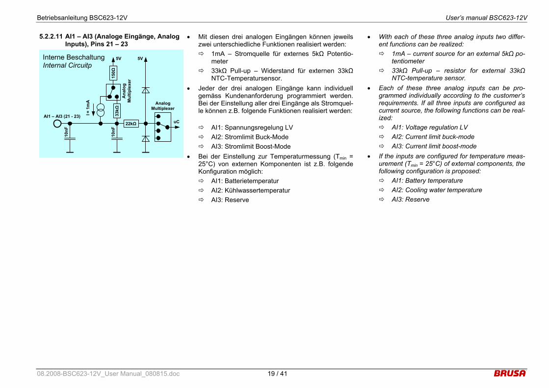
5.2.2.11 AI1 – AI3 (Analoge Eingänge, Analog Inputs), Pins 21 – 23
Interne Beschaltung Internal Circuitp
10nF
AI1 – AI3 (21 - 23)
5V
Analog Multiplexer
22kΩ
150Ω
33
kΩ
10nF
I = 1
mA
5V
Ana
log
Mul
tiple
xer
uC
• Mit diesen drei analogen Eingängen können jeweils zwei unterschiedliche Funktionen realisiert werden: 1mA – Stromquelle für externes 5kΩ Potentio-
meter 33kΩ Pull-up – Widerstand für externen 33kΩ
NTC-Temperatursensor. • Jeder der drei analogen Eingänge kann individuell
gemäss Kundenanforderung programmiert werden. Bei der Einstellung aller drei Eingänge als Stromquel-le können z.B. folgende Funktionen realisiert werden:
AI1: Spannungsregelung LV AI2: Stromlimit Buck-Mode AI3: Stromlimit Boost-Mode
• Bei der Einstellung zur Temperaturmessung (Tmin = 25°C) von externen Komponenten ist z.B. folgende Konfiguration möglich: AI1: Batterietemperatur AI2: Kühlwassertemperatur AI3: Reserve
• With each of these three analog inputs two differ-ent functions can be realized: 1mA – current source for an external 5kΩ po-
tentiometer 33kΩ Pull-up – resistor for external 33kΩ
NTC-temperature sensor. • Each of these three analog inputs can be pro-
grammed individually according to the customer’s requirements. If all three inputs are configured as current source, the following functions can be real-ized: AI1: Voltage regulation LV AI2: Current limit buck-mode AI3: Current limit boost-mode
• If the inputs are configured for temperature meas-urement (Tmin = 25°C) of external components, the following configuration is proposed: AI1: Battery temperature AI2: Cooling water temperature AI3: Reserve
08.2008-BSC623-12V_User Manual_080815.doc 19 / 41
Betriebsanleitung BSC623-12V User’s manual BSC623-12V
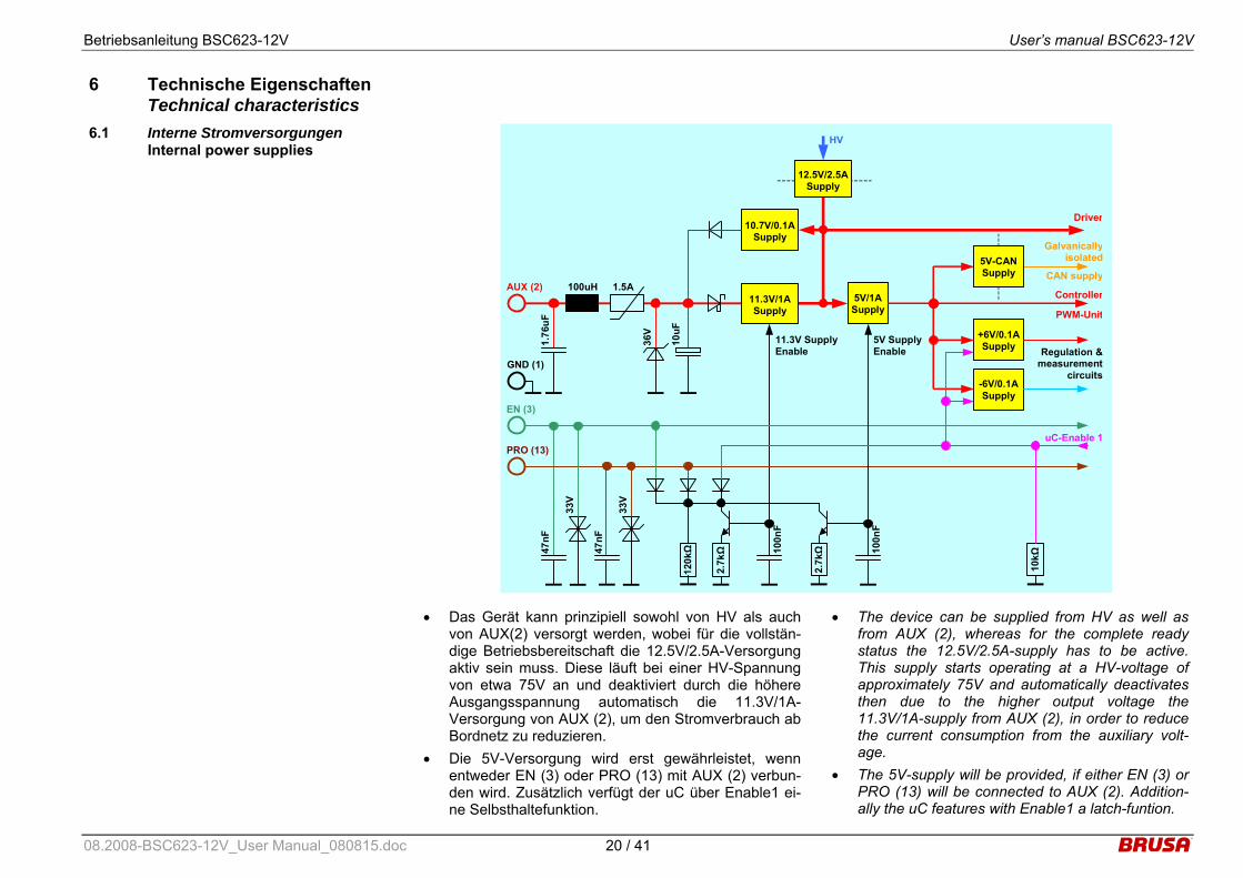
6 Technische Eigenschaften Technical characteristics
6.1 Interne Stromversorgungen Internal power supplies
1.76
uF
AUX (2) 100uH 1.5A
Regulation & measurement
circuits
36V
5V/1A Supply
10uF
HV
11.3V/1A Supply
10.7V/0.1A Supply
PRO (13)
47nF
EN (3)
2.7kΩ
120kΩ
5V Supply Enable
100n
F
11.3V Supply Enable
47nF
2.7kΩ
100n
F
uC-Enable 1
10kΩ
Driver
+6V/0.1A Supply
-6V/0.1A Supply
5V-CAN Supply
12.5V/2.5ASupply
GND (1)
33V
33V
Galvanicallyisolated
CAN supply
Controller
PWM-Unit
• Das Gerät kann prinzipiell sowohl von HV als auch von AUX(2) versorgt werden, wobei für die vollstän-dige Betriebsbereitschaft die 12.5V/2.5A-Versorgung aktiv sein muss. Diese läuft bei einer HV-Spannung von etwa 75V an und deaktiviert durch die höhere Ausgangsspannung automatisch die 11.3V/1A-Versorgung von AUX (2), um den Stromverbrauch ab Bordnetz zu reduzieren.
• Die 5V-Versorgung wird erst gewährleistet, wenn entweder EN (3) oder PRO (13) mit AUX (2) verbun-den wird. Zusätzlich verfügt der uC über Enable1 ei-ne Selbsthaltefunktion.
• The device can be supplied from HV as well as from AUX (2), whereas for the complete ready status the 12.5V/2.5A-supply has to be active. This supply starts operating at a HV-voltage of approximately 75V and automatically deactivates then due to the higher output voltage the 11.3V/1A-supply from AUX (2), in order to reduce the current consumption from the auxiliary volt-age.
• The 5V-supply will be provided, if either EN (3) or PRO (13) will be connected to AUX (2). Addition-ally the uC features with Enable1 a latch-funtion.
08.2008-BSC623-12V_User Manual_080815.doc 20 / 41
Betriebsanleitung BSC623-12V User’s manual BSC623-12V
• Um bei Bedarf einen autarken Betrieb des Geräts zu gewährleisten, ist eine 10.7V/0.1A-Versorgung imp-lementiert. Auf diese Weise kann beispielsweise EN (3) durch eine Verbindung mit AUX (2) im kundensei-tigen Stecker aktiviert werden, sodass das Gerät im-mer eingeschaltet ist.
• Die 12.5V/2.5A-Versorgung ist ebenfalls mit der – auch im Hoch-/Tiefsetzsteller eingesetzten – Auto-kommutierung-Topologie realisiert. Diese Speisung ist galvanisch vom Hochspannungskreis getrennt und funktioniert zudem ohne Optokoppler.
• Im Hochsetzstellbetrieb werden die Treiber beim Hochstarten zu Beginn von AUX(2) versorgt.
• Sämtliche Versorgungsschaltkreise sind kurzschluss-fest.
• Die Signalmasse (GND (1)) ist von der Leistungs-masse (LV-) galvanisch getrennt, um Potentialver-schleppungen bzw. Masseschleifen zu verhindern.
• A 10.7V/0.1A-supply is implemented, in order to ensure an autarkic operation of the device, if re-quired. Thus, EN (3) for instance could be acti-vated by a connection to AUX (2) in the customer-side connector, so that the device will be perma-nently switched on.
• The 12.5V/2.5A-supply is realized again with the – also in the buck/boost converter used – Auto-commutation-topology. This supply is galvanically isolated from the high voltage circuit and further-more functions without an optocoupler.
• In boost mode the drivers will be supplied from AUX (2) in the very beginning of the start-up.
• All supply circuits are short-circuit-proof.
• The signal ground (GND (1)) is galvanically iso-lated from the power ground (LV-), in order to avoid accidental energisation, resp. ground loops.
08.2008-BSC623-12V_User Manual_080815.doc 21 / 41
Betriebsanleitung BSC623-12V User’s manual BSC623-12V
6.2 Zuverlässigkeit Reliabilty
6.2.1 Überlastschutz - Derating Overload protection – derating
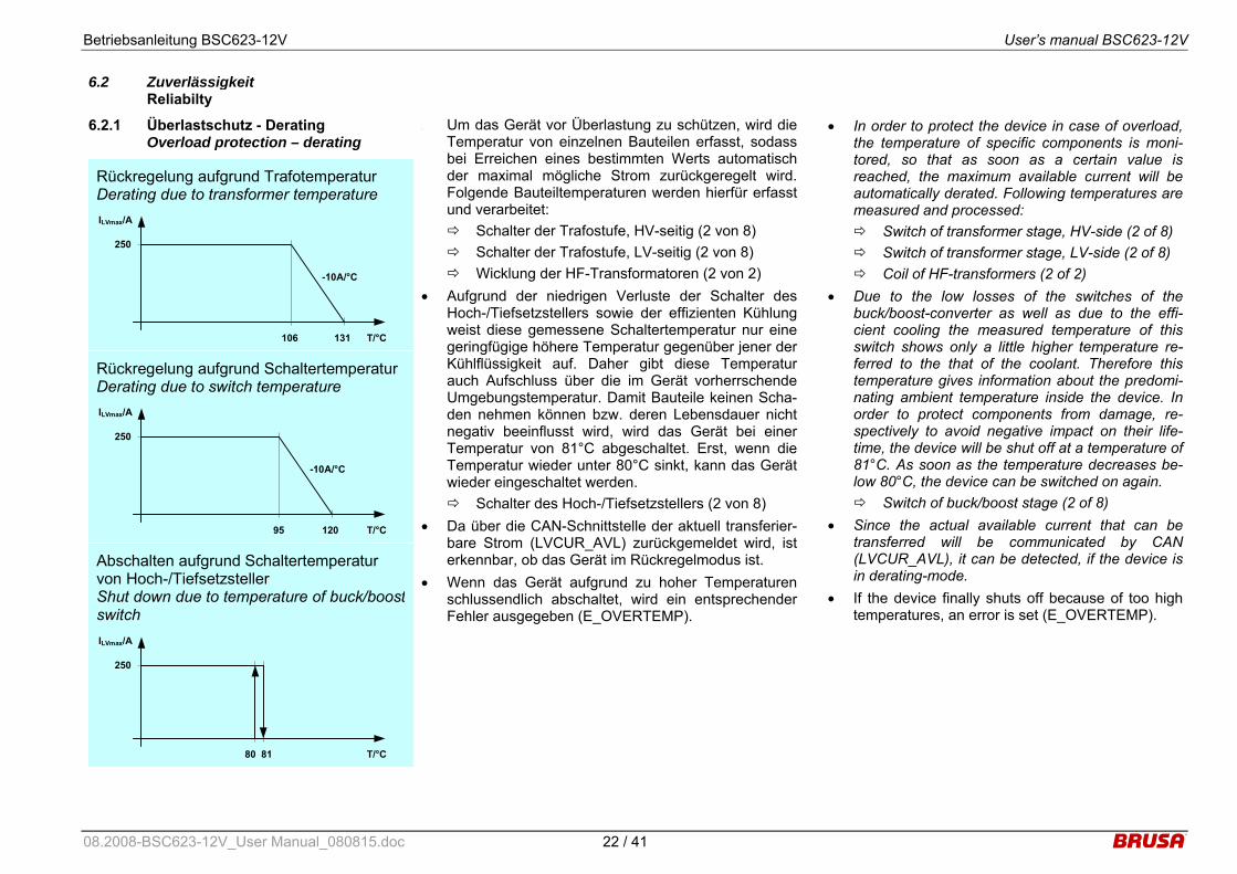
Rückregelung aufgrund Trafotemperatur Derating due to transformer temperature
T/°C131 106
-10A/°C
ILVmax/A
250
Rückregelung aufgrund SchaltertemperaturDerating due to switch temperature
T/°C120 95
-10A/°C
ILVmax/A
250
Abschalten aufgrund Schaltertemperatur von Hoch-/Tiefsetzsteller Shut down due to temperature of buck/boostswitch ILVmax/A
T/°C81 80
250
• Um das Gerät vor Überlastung zu schützen, wird die Temperatur von einzelnen Bauteilen erfasst, sodass bei Erreichen eines bestimmten Werts automatisch der maximal mögliche Strom zurückgeregelt wird. Folgende Bauteiltemperaturen werden hierfür erfasst und verarbeitet:
Schalter der Trafostufe, HV-seitig (2 von 8) Schalter der Trafostufe, LV-seitig (2 von 8) Wicklung der HF-Transformatoren (2 von 2)
• Aufgrund der niedrigen Verluste der Schalter des Hoch-/Tiefsetzstellers sowie der effizienten Kühlung weist diese gemessene Schaltertemperatur nur eine geringfügige höhere Temperatur gegenüber jener der Kühlflüssigkeit auf. Daher gibt diese Temperatur auch Aufschluss über die im Gerät vorherrschende Umgebungstemperatur. Damit Bauteile keinen Scha-den nehmen können bzw. deren Lebensdauer nicht negativ beeinflusst wird, wird das Gerät bei einer Temperatur von 81°C abgeschaltet. Erst, wenn die Temperatur wieder unter 80°C sinkt, kann das Gerät wieder eingeschaltet werden. Schalter des Hoch-/Tiefsetzstellers (2 von 8)
• Da über die CAN-Schnittstelle der aktuell transferier-bare Strom (LVCUR_AVL) zurückgemeldet wird, ist erkennbar, ob das Gerät im Rückregelmodus ist.
• Wenn das Gerät aufgrund zu hoher Temperaturen schlussendlich abschaltet, wird ein entsprechender Fehler ausgegeben (E_OVERTEMP).
• In order to protect the device in case of overload, the temperature of specific components is moni-tored, so that as soon as a certain value is reached, the maximum available current will be automatically derated. Following temperatures are measured and processed: Switch of transformer stage, HV-side (2 of 8) Switch of transformer stage, LV-side (2 of 8) Coil of HF-transformers (2 of 2)
• Due to the low losses of the switches of the buck/boost-converter as well as due to the effi-cient cooling the measured temperature of this switch shows only a little higher temperature re-ferred to the that of the coolant. Therefore this temperature gives information about the predomi-nating ambient temperature inside the device. In order to protect components from damage, re-spectively to avoid negative impact on their life-time, the device will be shut off at a temperature of 81°C. As soon as the temperature decreases be-low 80°C, the device can be switched on again. Switch of buck/boost stage (2 of 8)
• Since the actual available current that can be transferred will be communicated by CAN (LVCUR_AVL), it can be detected, if the device is in derating-mode.
• If the device finally shuts off because of too high temperatures, an error is set (E_OVERTEMP).
08.2008-BSC623-12V_User Manual_080815.doc 22 / 41

Betriebsanleitung BSC623-12V User’s manual BSC623-12V
6.2.2 Kurzschlussschutz Short circuit protection
• Da die Trafostufe aufgrund ihrer resonant taktenden Topologie einen bestimmten Innenwiderstand hat, ist diese und damit das Gerät prinzipiell kurzschlussfest. Dies hat zur Folge, dass im Fall eines Kurzschluss, der extern durch den Anwender verursacht wird, die Spannung zusammenbricht und zu einem Unter-spannungsfehler führt.
• Im Tiefsetzstellbetrieb wird bei einem Kurzschluss auf der LV-Seite Unterspannung erkannt.
• Im Hochsetzstellbetrieb wird bei einem Kurzschluss auf der HV-Seite Unterspannung erkannt.
• Natürlich wird unabhängig vom Betriebsmodus auch auf dem jeweiligen Leistungseingang Unterspannung erkannt.
• Since the transformer stage with its resonant to-pology has a certain internal resistance, it and therefore the device is basically short-circuit-proof. As a consequence, in case of a short-circuit, that is caused by the user externally, the voltage drops and leads to an undervoltage error.
• In buckmode a short-circuit on the LV-side will be detected by undervoltage.
• In boostmode a short-circuit on the HV-side will be detected by undervoltage.
• Regardless of the operation mode undervoltage will be detected on the corresponding power input as well.
6.2.3 HV-Überspannungs-Abschaltung HV-Overvoltage shut-down
• Das Gerät verfügt über zwei verschiedene Möglich-keiten, um Überspannung (E_HV_OVERVOL) zu er-kennen: Schnelle HW-Überspannungserkennung Langsame SW-Überspannungserkennung
• Die schnelle HW-Überspannungserkennung schaltet das Gerät unmittelbar ab, wenn die HV-Spannung ungefähr 470V überschreitet. Ein Fehler wird aber nur dann erkannt, wenn dies mindestens 4ms der Fall ist. Wenn die Überspannung innerhalb der 4ms wieder unter den Grenzwert sinkt, schaltet das Gerät automatisch wieder ein.
• Die langsame SW-Überspannungserkennung schal-tet das Gerät ab, wenn die HV-Spannung 431V er-reicht. Das Gerät schaltet automatisch wieder ein, wenn die HV-Spannung unter 429V liegt.
• The device features two different possibilities, in order to detect overvoltage (E_HV_OVERVOL):
Fast HW-overvoltage detection Slow SW-overvoltage detection
• The fast HW-overvoltage detection shuts off the device immediately, if the HV-voltage exceeds approximately 470V. An error will only be de-tected, if this is the case for at least 4ms. If the overvoltage drops below the limit value within 4ms, the device switches on again automatically.
• The slow SW-overvoltage detection shuts off the device, if the HV-voltage reaches 431V. The de-vice will be activated again automatically as soon as the HV-voltage is below 429V.
08.2008-BSC623-12V_User Manual_080815.doc 23 / 41
Betriebsanleitung BSC623-12V User’s manual BSC623-12V
6.2.4 LV-Überspannungs-Abschaltung LV-Overvoltage shut-down
• Das Gerät verfügt über zwei verschiedene Möglich-keiten, um Überspannung (E_LV_OVERVOL) zu er-kennen: Schnelle HW-Überspannungserkennung Langsame SW-Überspannungserkennung
• Die schnelle HW-Überspannungserkennung schaltet das Gerät unmittelbar ab, wenn die LV-Spannung ungefähr 20V überschreitet. Ein Fehler wird aber nur dann erkannt, wenn dies mindestens 4ms der Fall ist. Wenn die Überspannung innerhalb der 4ms wieder unter den Grenzwert sinkt, schaltet das Gerät auto-matisch wieder ein.
• Die langsame SW-Überspannungserkennung schal-tet das Gerät ab, wenn die LV-Spannung 16.4V er-reicht. Das Gerät schaltet automatisch wieder ein, wenn die LV-Spannung unter 16.2V liegt.
• The device features two different possibilities, in order to detect overvoltage (E_LV_OVERVOL):
Fast HW-overvoltage detection Slow SW-overvoltage detection
• The fast HW-overvoltage detection shuts off the device immediately, if the LV-voltage exceeds ap-proximately 20V. An error will only be detected, if this is the case for at least 4ms. If the overvoltage drops below the limit value within 4ms, the device switches on again automatically.
• The slow SW-overvoltage detection shuts off the device, if the LV-voltage reaches 16.4V. The de-vice will be activated again automatically as soon as the LV-voltage is below 16.2V.
6.2.5 HV-Unterspannungs-Abschaltung HV-Undervoltage shut-down
• Die HV-Unterspannungserkennung schaltet die Leis-tungsstufe ab und gibt einen Fehler aus (E_HV_UNDERVOL), wenn die HV-Spannung unter 165V sinkt.
• Diese Fehlererkennung ist beim Starten des Geräts im Hochsetzbetrieb für 3s deaktiviert.
• The HV-undervoltage detection shuts down the power stage and sets an error (E_HV_UNDERVOL), if the HV-voltage drops be-low 165V.
• This error detection is deactivated for 3s at start-up of the device in boost mode.
6.2.6 LV-Unterspannungs-Abschaltung LV-Undervoltage shut-down
• Die LV-Unterspannungserkennung schaltet die Leis-tungsstufe ab und gibt einen Fehler aus (E_LV_UNDERVOL), wenn die LV-Spannung unter 7V sinkt.
• Diese Fehlererkennung ist beim Starten des Geräts im Tiefsetzbetrieb für 5s deaktiviert.
• The LV-undervoltage detection shuts down the power stage and sets an error (E_LV_UNDERVOL), if the LV-voltage drops be-low 7V.
• This error detection is deactivated for 5s at start-up of the device in boost mode.
08.2008-BSC623-12V_User Manual_080815.doc 24 / 41

Betriebsanleitung BSC623-12V User’s manual BSC623-12V
6.2.7 Interlock – Safety Line Interlock – Safety Line
• Mittels dieser Funktion wird überprüft, ob die Stecker ordnungsgemäss angeschlossen sind. Im Gerät ist sowohl eine interne als auch eine externe Interlo-ckerkennung implementiert, die unabhängig vonein-ander funktionieren und einen Fehler auslösen kön-nen (CRE_INTERLOCK).
• Während die interne Erkennung zwar immer aktiv ist, aber ausschliesslich den eigenen HV-Stecker über-prüft, kann zusätzlich optional das Gerät über die entsprechenden Pins am Steuerstecker in eine Inter-lockschleife eingebunden werden (externe Interlo-ckerkennung). Auf diese Weise kann ein entspre-chendes Gerät im Interlockkreis den ordnungsge-mässen Kontakt aller Steckverbindungen überprüfen.
• Der BSC623-12V kann aber auch selber erkennen, ob die Interlockschleife offen ist. Der hierzu einzu-prägende Strom muss im Bereich von 18-22mA lie-gen. Wenn der Strom unter etwa 10mA sinkt, wird ein Fehler erkannt.
• This feature allows to monitor if the connectors are connected properly. There is an internal as well as an external interlock detection imple-mented in the device, that function and set an er-ror independently (CRE_INTERLOCK).
• While the internal detection is always active but only monitors the own HV-connector, it is also op-tionally possible to integrate the device into an in-terlock loop by using the corresponding pins on the control connector (external interlock detec-tion). By this means a dedicated device in the in-terlock loop can monitor the proper connection of all connectors.
• The BSC623-12V itself is able to detect as well, if the interlock loop is open. The current that has to be injected, must be in the range of 18-22mA. If the current drops below approximately 10mA, an error will be detected.
6.2.8 HV – Automatische Entladung HV – Automatic discharge
• Wenn das Gerät von der Hochspannung getrennt wird, entladen sich die internen HV-Schaltkreise in-nerhalb von 350ms auf Werte unter 50V.
• If the device is disconnected from the high volt-age, the internal HV-circuitries are discharged within 350ms to values below 50V.
08.2008-BSC623-12V_User Manual_080815.doc 25 / 41

Betriebsanleitung BSC623-12V User’s manual BSC623-12V
6.3 EMV – Betrachtungen EMC – considerations
6.3.1 Topologievorteile Advantages of the topology
• Der Leistungsteil der Trafostufe basiert auf einer re-sonant schaltenden Topologie, sodass das Schalten jeweils im Strom-Nulldurchgang stattfindet. Der für die Spannungsanpassung notwendige Hoch- bzw. Tiefsetzsteller nutzt das sogenannte Autokommutie-rung – Prinzip, dass in einem sanften Kommutieren des Brückenpunktes resultiert. Aufgrund der wesent-lich langsameren Flanken von Strom und Spannung können die EMV – Störungen im Vergleich zu hart-schaltenden Topologien um ein erhebliches Mass re-duziert werden.
• The power stage of the transformer stage is based upon a resonant switching topology, so that the switching process itself takes place in zero-current state. The buck/boost-converter, which is necessary for the voltage regulation, uses the so-called Autocommutation – principle, which results in a smooth commutation of the bridge point. Due to the significant slower slopes of current and volt-age the EMC – interferences are considerably reduced compared to hard-switching topologies.
08.2008-BSC623-12V_User Manual_080815.doc 26 / 41

Betriebsanleitung BSC623-12V User’s manual BSC623-12V
6.3.2 AUX – Filterkonzept AUX – filter concept
• Um eine bestmögliche Dämpfung der leitungsgebun-denen Störungen zu erreichen, sind alle Pins des Steuersteckers durch SMD-Kondensatoren auf GND gefiltert. GND ist wiederum sehr nieder-impedant mit dem Gehäuse verbunden. Auf diese Weise kann ein Übersprechen von Gleichtaktstörungen von einem Pin auf andere weitgehend unterdrückt werden.
• AUX ist zusätzlich mit einem X-Filter versehen. Aus-serdem ist der Pin durch eine flinke PTC-Sicherung und einer 36V-Suppressordiode gegenüber Surge- und Burst-Störungen geschützt.
• Die CAN – Schnittstelle ist durch eine spezielle Dros-sel gegenüber Gleichtaktstörungen gefiltert.
• Alle Pins des Steuersteckers sind gegen luft- oder kontaktentladene ESD – Störungen geschützt. Bei der CAN- und RS232 – Schnittstelle erfolgt dies durch spezielle ESD – Dioden.
• Für die Unterdrückung von hochfrequenten Gleich-taktstörungen sind alle Pins durch einen Ferritkern geführt.
• Weitere Details zur Beschaltung der Steuerstecker-pins siehe unter 5.2 Steueranschluss.
• In order to obtain a best possible attenuation of conducted interferences all pins of the control connector are filtered by SMD-capacitors to GND. GND itself is connected to the housing with a very low impedance. Hence the cross talk of common mode interferences can be suppressed exten-sively.
• AUX is additionally provided with a X-filter. Fur-thermore this pin is protected against surge- and burst disturbances with a fast ptc-fuse and a 36V-suppressor diode.
• The CAN – interface is filtered by a special choke against common mode interferences.
• All pins of the control connector are protected against air- or contact-discharged ESD - distur-bances. The CAN- and RS232 – interface are therefore equipped with special ESD – diodes.
• In order to suppress high frequent common mode interferences all pins are conducted through a fer-rite core.
• Refer to 5.2 Control interface for further details re-garding the circuitry of the control connector.
08.2008-BSC623-12V_User Manual_080815.doc 27 / 41

Betriebsanleitung BSC623-12V User’s manual BSC623-12V
6.3.3 LV – Filterkonzept LV – filter concept
Low Voltage 8…16VDC max. 250A
Ls ELV2 CX ELV1
LV-Filter
• Die Kondensatoren ELV1 und ELV2 sind als SMD-
Tantalkondensatoren ausgeführt, was eine sehr nie-der-impedante Anbindung ermöglicht.
• Die Kondensatoren CX befinden sich direkt am LV-Leistungsstecker. Da im Fall eines Defekts dieser Fil-terkondensatoren (z.B.: Kurzschluss durch Bruch des Bauteils) die LV-Sicherung kein Schutz für das Gerät bieten kann, werden spezielle äusserst zuverlässige Typen eingesetzt, die eine enorm hohe Robustheit gegenüber mechanischen Kräften aufweisen.
Bauteil Wert Einheit
ELV1 660.0 uF
Ls 364.0 nH
ELV2 660.0 uF
CX 1.2 uF
• The capacitors ELV1 and ELV2 are tantalum SMD-
capacitors, which ensures a very low-impedant connection.
• The capacitors CX are placed directly at the LV-power connector. Since in case of damage of these filter capacitors (i.e.: short circuit due to crack of component) the LV-fuse cannot protect the device, special extremely reliable types are used, that offer an enormous high robustness against mechanical impact.
Component Value Unit
ELV1 660.0 uF
Ls 364.0 nH
ELV2 660.0 uF
CX 1.2 uF
08.2008-BSC623-12V_User Manual_080815.doc 28 / 41

Betriebsanleitung BSC623-12V User’s manual BSC623-12V
6.3.4 HV – Filterkonzept HV – filter concept
HV-Filter
High Voltage 170…425VDC
max. 21A
Cb
Buck/Boost-Converter External HV components(Inverter, power source, ...)
Cy2 Cy2
Lh
Cye Cye
Cxe
Cy1 Cy1
Ls
• Die am Eingang befindliche HV-Drossel ist prinzipiell
als Gleichtaktdrossel (Lh) ausgeführt, hilft aber auch durch die vorhandene Streuinduktivität (Ls), um Ge-gentaktstörungen zu filtern.
• Die bedrahteten Y-Kondensatoren (Cy2) bilden zu-sammen mit der Gleichtaktdrossel (Lh) das Gleich-taktfilter.
• Um besonders hochfrequente Gleichtaktstörungen zu filtern, sind direkt am Eingang sehr nieder-impedante Y-Kondensatoren (Cy1) geschaltet.
• Der Zwischenkreiskondensator (Cb) formt gemein-sam mit der Streuinduktivität der HV-Drossel (Ls) das Gegentaktfilter. Aufgrund der hohen Taktfre-quenzen kann der Kondensator sehr klein dimensio-niert werden, was eine sehr rasche Entladung des Zwischenkreises ermöglicht.
Bauteil Wert Einheit
Cy1 6.6 nF
Lh 2314.0 uH
Ls 5.8 uH
Cy2 15.0 nF
Cb 16.2 uF
• The HV-choke located at the input is basically de-
signed as a common mode choke (Lh). Even though it helps to filter differential mode distur-bances due to the existing stray inductance (Ls).
• The through-hole Y-capacitors build together with the common mode choke (Lh) the common mode filter.
• In order to filter particularly high-frequency com-mon mode disturbances, very low-impedant Y-capacitors (Cy1) are connected directly to the in-put.
• The DC-link capacitor (Cb) forms jointly with the stray inductance of the HV-choke (Ls) the differen-tial mode filter. Due to the high switching frequen-cies this capacitor can be designed very little, which enhances a quick discharge of the DC-link.
Component Value Unit
Cy1 6.6 nF
Lh 2314.0 uH
Ls 5.8 uH
Cy2 15.0 nF
Cb 16.2 uF
08.2008-BSC623-12V_User Manual_080815.doc 29 / 41

Betriebsanleitung BSC623-12V User’s manual BSC623-12V
6.3.5 Taktfrequenzen Clock frequencies
• Die im Gerät vorkommenden taktenden Schaltungs-teile weisen verschiedene Frequenzen auf:
• Quarz – Oszillator: 6.00MHz
• Microcontroller Hitachi HD64F7045FI28: 24.00MHz (4 x fQuarz)
• Hoch-/Tiefsetzsteller: 30 - 135kHz (@ ILV = 250A)
• Trafostufe: 220kHz
• Versorgung HV → 12.4VDC: UHV = 85V: 88kHz UHV = 170V: 126kHz UHV = 240V: 142kHz UHV = 450V: 166kHz
• Versorgung 12.4VDC → 5VDC: 260kHz
• Versorgung AUX → 11.7VDC: 260kHz
• Versorgung CAN: 230kHz
• The clocked circuitries inside the device work with various frequencies:
• Quartz – oscillator: 6.00MHz
• Microcontroller Hitachi HD64F7045FI28: 24.00MHz (4 x fquartz)
• Buck/boost stage: 30 - 135kHz (@ ILV = 250A)
• Transformer stage: 220kHz
• Supply HV → 12.4VDC: UHV = 85V: 88kHz UHV = 170V: 126kHz UHV = 240V: 142kHz UHV = 450V: 166kHz
• Supply 12.4VDC → 5VDC: 260kHz
• Supply AUX → 11.7VDC: 260kHz
• Supply CAN: 230kHz
08.2008-BSC623-12V_User Manual_080815.doc 30 / 41

Betriebsanleitung BSC623-12V User’s manual BSC623-12V
7 Inbetriebnahme des Gerätes Start-up the device
• Bevor das Gerät in Betrieb genommen werden kann, müssen folgende Tätigkeiten durchgeführt werden. Nehmen Sie sich Zeit dafür und lesen Sie die Anlei-tung gründlich durch. Die Arbeiten dürfen nur durch einen Fachmann durchgeführt werden.
• Before the device can be taken into operation fol-lowing steps have to be done. Take your time for it and read the manual carefully. The mounting work has to be done by an expert.
7.1 Befestigung des Geräts im Fahrzeug Mounting of the device in the vehicle
• Das Gerät verfügt auf der Unterseite über 6 Befesti-gungslöcher mit einer Tiefe von 15mm mit folgenden Daten hinsichtlich Gewinde: 4 Montagelöcher mit Gewinde M5x11 2 Montagelöcher mit Gewinde M5x15
• Das Gehäuse ist für Befestigungsdrehmomente bis 5Nm ausgelegt.
• Wir empfehlen die Verwendung von Schrauben der Festigkeitsklasse 8.8, die mit einem Drehmoment von 5Nm angezogen werden.
• The device has 6 mounting holes with a depth of 15mm at the bottom, whereas these have follow-ing specification regarding the thread: 4 mounting holes with thread M5x11 2 mounting holes with thread M5x15
• The housing is specified for mounting torques of up to 5Nm.
• We recommend the use of screws with a strength class of 8.8, which can be mounted with a torque of 5Nm.
Befestigungslöcher (Tiefe 15mm) mit Gewinde M5x11 Mounting holes (depth 15mm) with thread M5x11
Befestigungslöcher (Tiefe 15mm) mit Gewinde M5x15 Mounting holes (depth 15mm) with thread M5x15
08.2008-BSC623-12V_User Manual_080815.doc 31 / 41

Betriebsanleitung BSC623-12V User’s manual BSC623-12V
7.2 Anschluss des Gerätes Connecting the device
• Mitgelieferte HV und LV – Leistungsstecker mit ei-nem den Anforderungen (Stromstärke, Schirmung,...) entsprechendem Kabel konfektionieren. Auf Anfrage kann dies auch durch BRUSA durchgeführt werden. Die Länge des LV-Kabels zwischen 12V-Batterie und BSC623-12V darf 2m nicht überschreiten, damit der HV-Spannungsregler im Hochsetzstellbetrieb stabil bleibt.
• Mitgelieferter Steuerstecker den Anforderungen (EMV, Umwelteinflüsse,...) entsprechend konfektio-nieren, wobei nur die tatsächlich verwendeten Pins verdrahtet werden müssen. Folgende Pins sind für den Betrieb zwingend notwendig:
Der Pin EN muss über einen Schalter mit AUX
verdrahtet werden (z.B.: im Fahrzeug über den Zündschlüssel mit dem Bordnetz).
• Wasserkühlung an den Kühlwasserstutzen des Gerä-tes anschliessen und sicherstellen, dass die Durch-flussrate mindestens 4l/min beträgt. Die Schlauch-schellen müssen so positioniert werden wie auf dem Bild links abgebildet, damit es keine Kollision mit dem HV- und Steuerstecker gibt.
• Leistungs- und Steuerstecker am Gerät anschlies-sen, wobei noch keine HV-Spannung anliegen darf.
Nr. Abk. Funktion
1 GND Masse (Bordnetz Minus, Klemme 31)
2 AUX +12V (Bordnetz Plus, Klemme 30)
3 EN Enable (Power ON, Klemme 15)
9 CNL CAN Low
10 CNH CAN High
• Assemble delivered HV and LV – power connec-tors according to the requirements (current, shielding,...) with an appropriate cable. Upon re-quest this can also be done by BRUSA. The length of the LV-cable between 12V-battery and BSC623-12V must not exceed 2m, in order to en-sure stable operation of the HV-voltage regulator in boost mode.
• Assemble delivered control connector according to the requirements (EMC, environmental influ-ence,…), whereas only the actual pins which are used have to be wired. Following pins are abso-lutely necessary for operation:
The pin EN has to be wired to AUX by a
switch (e.g.: in the vehicle by the ignition key to the auxiliary supply).
• Connect the water cooling at the cooling pipes of the device and ensure the flow rate is at least 4l/min. The hose clamp must be positioned ac-cording to the picture shown on the left in order to avoid collisions with the HV- and control connec-tor.
• Connect the power and control connectors to the device. Ensure that no high voltage is applied yet.
No. Abbr. Function
1 GND Ground (Auxiliary voltage minus, terminal 31)
2 AUX +12V (Auxiliary voltage plus, terminal 30)
3 EN Enable (Power ON, terminal 15)
9 CNL CAN low
10 CNH CAN high
LV(+) –Connector
Control –Connector HV – Connector
Coolant Inlet Coolant Outlet
LV(-) – Connection
08.2008-BSC623-12V_User Manual_080815.doc 32 / 41

Betriebsanleitung BSC623-12V User’s manual BSC623-12V
7.3 Bedienung des Gerätes Operation of the device
• Hochspannung allenfalls vorladen, bevor die Verbin-dungen mittels Schütze geschlossen werden.
• Pin EN mit AUX verbinden (Zündschlüssel betätigen, Schalter schliessen).
• CAN – Bedienoberfläche starten und „Start“-Button drücken, um die Kommunikation mit dem Gerät zu ermöglichen. Mit dem Button „Run“ wie im Bild be-schrieben wird die Leistungsstufe aktiviert. Das Bild links stellt nur ein Beispiel dar wie das
Gerät mittels CAN gesteuert werden kann. CAN – Bedienoberflächen können auch durch den Kunden erstellt werden.
Die Kommunikation mit dem Gerät ist gewähr-leistet, wenn die Anzeige „Tx“ und „Rx“ blinkt.
• Damit der Hauptregler seine Funktion erfüllen kann, muss sichergestellt sein, dass kein Begrenzungsreg-ler im Eingriff ist.
• Das Gerät kann in jedem Betriebszustand durch er-neutes Betätigen des Button „Run“ und Deaktivieren des Pin EN abgeschaltet werden.
• Auch das schlagartige Wegschalten der Hochspan-nung (Öffnen der Schütze) ist zulässig.
• Precharge the high voltage before closing the connections by contactors.
• Connect the pin EN to AUX (activate ignition key, close switch).
• Start the CAN – user terminal and press the “Start”-button in order to allow communication with the device. With the button “Run” like described in the picture the power stage is activated. The picture on the left side shows only one
example of how to control the device by CAN. CAN – user terminals can be designed by the customer as well.
Communication with the device is ensured, if the displays “Tx” and “Rx” are blinking.
• In order to allow the main regulator to fulfill its function ensure that no limiting regulator is active.
• The device can be switched off in any operational condition by pressing again the button “Run” and deactivating the pin EN.
• The sudden disconnection of the high voltage (open the contactors) is permissible as well.
7.4 Programmieren der Firmware Download the firmware
• Beim BSC623-12V besteht die Möglichkeit die Firm-ware des Gerätes zu aktualisieren. Dies darf jedoch ausdrücklich nur nach Absprache mit BRUSA erfol-gen. Die Firmware kann von einem gewöhnlichen PC über die RS232 – Schnittstelle programmiert werden. Nachfolgend sind die notwendigen Schritte genauer erläutert.
• The BSC623-12V has the possibility to be up-dated with a new firmware. This may only be done with agreement of BRUSA. The firmware can be downloaded from an ordinary PC over the RS232 – interface. The necessary steps are described hereafter.
7.4.1 PC - Systemanforderungen Requirements to the PC - system
• Betriebssystem Windows 95/98, Windows NT, Win-dows 2000 und Windows XP (Installationsschritte können dann leicht von den Anweisungen abwei-chen).
• Serielle Schnittstelle RS232
• Operating system Windows 95/98, Windows NT, Windows 2000 und Windows XP (Installation steps may slightly be different from instructions).
• Serial interface RS232
08.2008-BSC623-12V_User Manual_080815.doc 33 / 41

Betriebsanleitung BSC623-12V User’s manual BSC623-12V
7.4.2 Einstellungen am Gerät und PC Configuration of the device and PC
• Verbinden Sie den Pin PRO (Pin 13 des Steuerste-ckers) mit dem Pin AUX (Pin 2 des Steuersteckers).
• Stellen Sie eine Verbindung der RS232 – Schnittstel-le am Gerät mit der seriellen Schnittstelle COM1 am Computer her.
• Stellen Sie sicher, dass die RS232 – Schnittstelle am Computer von keiner anderen Anwendung belegt ist.
• Versorgen Sie das Gerät entweder von Hochspan-nung oder vom Bordnetz.
• Für detailierte Informationen bezüglich der Verdrah-tung siehe unter 5.2 Steueranschluss.
• Connect the pin PRO (pin 13 of control connector) with the pin AUX (pin 2 of control connector).
• Provide a connection of the RS232 – interface at the device with the serial interface COM1 at the computer.
• Ensure that the RS232 – interface at the computer is not used by another application.
• Supply the device either from high voltage or from the auxiliary supply.
• For further information regarding the wiring refer to 5.2 control connector.
7.4.3 Installation der Programmier – Software Installation of the programming software
• Um eine neue Firmware programmieren zu können, muss das Hitachi „Flash Development Toolkit“ instal-liert werden. Dieses wird Ihnen auf Anfrage per Email zugeschickt. Nachfolgend ist die Installation genauer beschrieben.
• Starten Sie das Setup und folgen Sie den Installati-onsanweisungen.
• In order to download a new firmware the Hitachi “Flash Development Toolkit” has to be installed. This can be sent by email upon request. The in-stallation is described hereafter.
• Start the setup and follow the installation instruc-tions.
• „Hitachi/MCS“ aktivieren. • Activate “Hitachi/MCS”.
08.2008-BSC623-12V_User Manual_080815.doc 34 / 41
Betriebsanleitung BSC623-12V User’s manual BSC623-12V
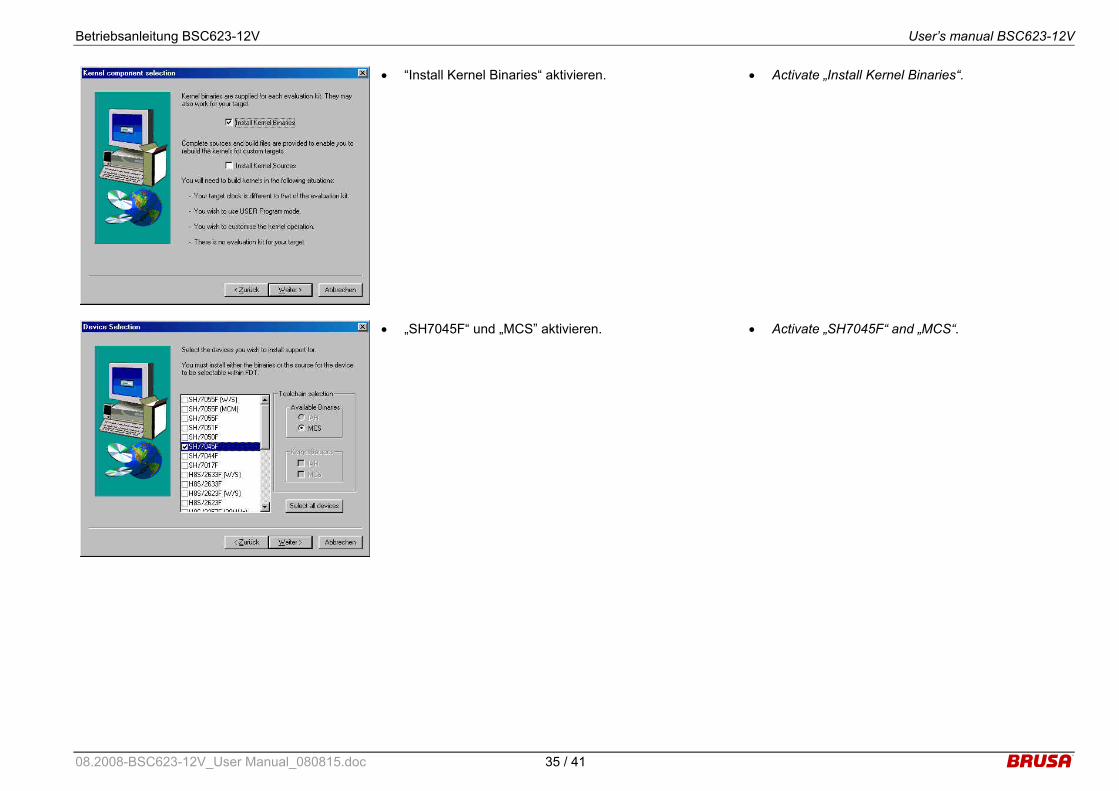
• “Install Kernel Binaries“ aktivieren. • Activate „Install Kernel Binaries“.
• „SH7045F“ und „MCS” aktivieren. • Activate „SH7045F“ and „MCS“.
08.2008-BSC623-12V_User Manual_080815.doc 35 / 41
Betriebsanleitung BSC623-12V User’s manual BSC623-12V
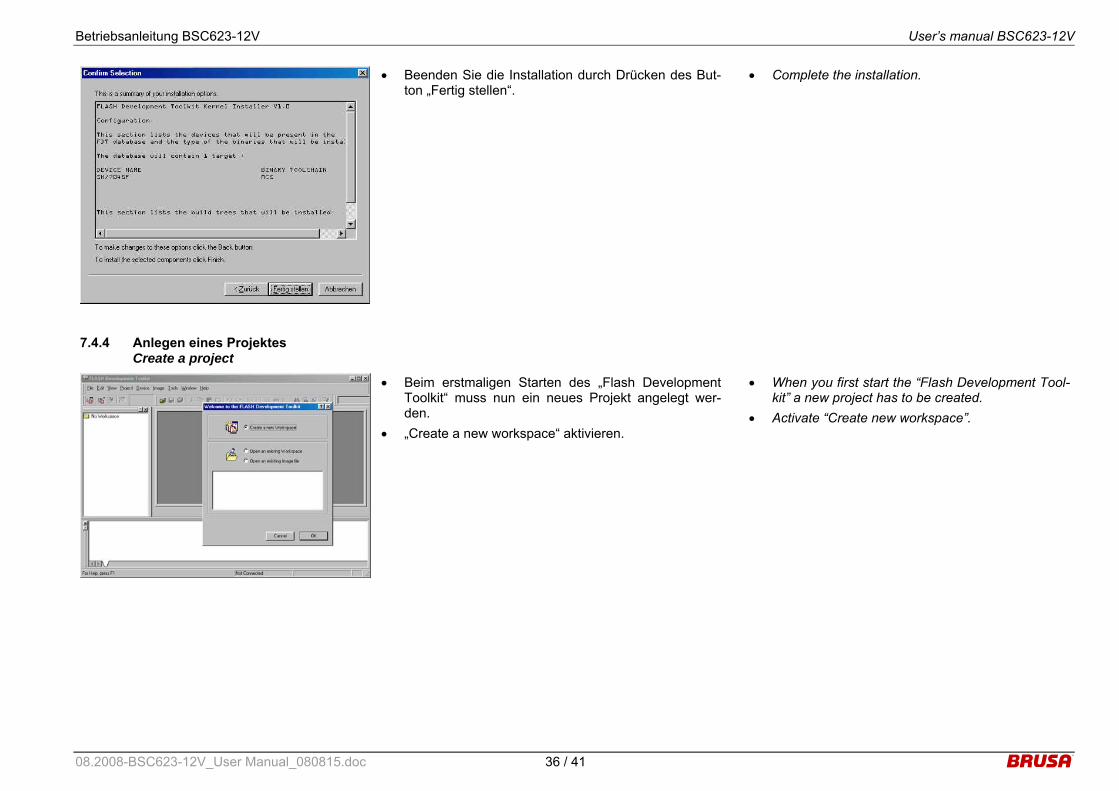
• Beenden Sie die Installation durch Drücken des But-ton „Fertig stellen“.
• Complete the installation.
7.4.4 Anlegen eines Projektes Create a project
• Beim erstmaligen Starten des „Flash Development Toolkit“ muss nun ein neues Projekt angelegt wer-den.
• „Create a new workspace“ aktivieren.
• When you first start the “Flash Development Tool-kit” a new project has to be created.
• Activate “Create new workspace”.
08.2008-BSC623-12V_User Manual_080815.doc 36 / 41

Betriebsanleitung BSC623-12V User’s manual BSC623-12V
• Im Feld „Workspace Name“ geben Sie “SHC1” ein. • Im Feld „Location“ geben Sie den von Ihnen ge-
wünschten Programmpfad ein.
• Insert „SHC1“ in the field „Workspace Name“. • Insert the corresponding program directory in the
field “Location”.
• Bestätigen Sie mit „Ja“. • Confirm with “Yes”.
• Im Feld „Project Name“ geben Sie den gewünschten Projektnamen ein (z.B.: BSC623-12V).
• Insert an appropriate project name in the field “Project Name” (e.g.: BSC623-12V).
08.2008-BSC623-12V_User Manual_080815.doc 37 / 41
Betriebsanleitung BSC623-12V User’s manual BSC623-12V
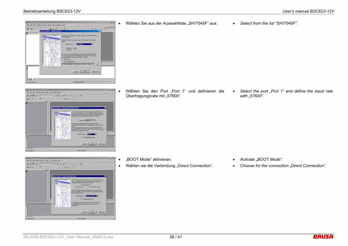
• Wählen Sie aus der Auswahlliste „SH/7045F“ aus. • Select from the list “SH/7045F”.
• Wählen Sie den Port „Port 1“ und definieren dieÜbertragungsrate mit „57600“.
• Select the port „Port 1“ and define the baud rate with „57600“.
• „BOOT Mode“ aktivieren. • Wählen sie die Verbindung „Direct Connection“.
• Activate „BOOT Mode“. • Choose for the connection „Direct Connection“.
08.2008-BSC623-12V_User Manual_080815.doc 38 / 41
Betriebsanleitung BSC623-12V User’s manual BSC623-12V
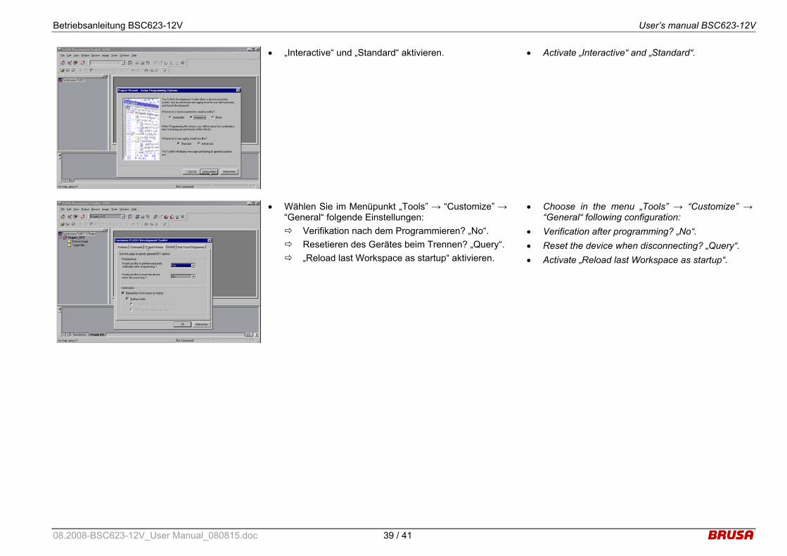
• „Interactive“ und „Standard“ aktivieren. • Activate „Interactive“ and „Standard“.
• Wählen Sie im Menüpunkt „Tools” → “Customize” → “General“ folgende Einstellungen: Verifikation nach dem Programmieren? „No“. Resetieren des Gerätes beim Trennen? „Query“. „Reload last Workspace as startup“ aktivieren.
• Choose in the menu „Tools” → “Customize” → “General“ following configuration:
• Verification after programming? „No“. • Reset the device when disconnecting? „Query“. • Activate „Reload last Workspace as startup“.
08.2008-BSC623-12V_User Manual_080815.doc 39 / 41
Betriebsanleitung BSC623-12V User’s manual BSC623-12V
7.4.5 Download der Firmware Download of the firmware
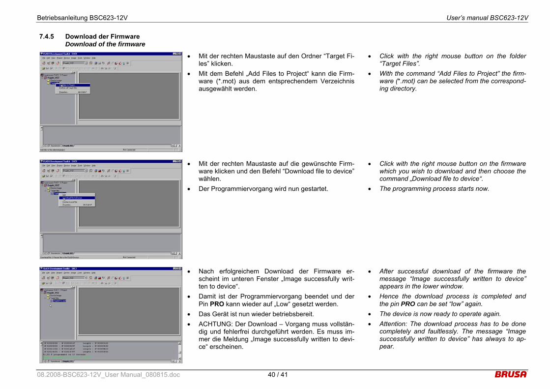
• Mit der rechten Maustaste auf den Ordner “Target Fi-les” klicken.
• Mit dem Befehl „Add Files to Project“ kann die Firm-ware (*.mot) aus dem entsprechendem Verzeichnis ausgewählt werden.
• Click with the right mouse button on the folder “Target Files”.
• With the command “Add Files to Project” the firm-ware (*.mot) can be selected from the correspond-ing directory.
• Mit der rechten Maustaste auf die gewünschte Firm-ware klicken und den Befehl “Download file to device” wählen.
• Der Programmiervorgang wird nun gestartet.
• Click with the right mouse button on the firmware which you wish to download and then choose the command „Download file to device“.
• The programming process starts now.
• Nach erfolgreichem Download der Firmware er-scheint im unteren Fenster „Image successfully writ-ten to device“.
• Damit ist der Programmiervorgang beendet und der Pin PRO kann wieder auf „Low“ gesetzt werden.
• Das Gerät ist nun wieder betriebsbereit. • ACHTUNG: Der Download – Vorgang muss vollstän-
dig und fehlerfrei durchgeführt werden. Es muss im-mer die Meldung „Image successfully written to devi-ce“ erscheinen.
• After successful download of the firmware the message “Image successfully written to device” appears in the lower window.
• Hence the download process is completed and the pin PRO can be set “low” again.
• The device is now ready to operate again. • Attention: The download process has to be done
completely and faultlessly. The message “Image successfully written to device” has always to ap-pear.
08.2008-BSC623-12V_User Manual_080815.doc 40 / 41
Betriebsanleitung BSC623-12V User’s manual BSC623-12V
8 Garantie Warranty
• Wir gewähren eine Garantie von 24 Monaten ab dem Kaufdatum auf Material- und Verarbeitungs-fehler.
• Die Garantie erlischt bei unsachgemässer Behand-lung des Gerätes.
• Technische Änderungen sind jederzeit ohne An-kündigung möglich.
• Wir weisen ausdrücklich darauf hin, dass mit die-sem Gerät lebensgefährliche Spannungen verarbei-tet werden können. Wir lehnen diesbezüglich jede Haftung ab.
• Wir übernehmen keine Haftung durch Folgeschä-den, die durch die Anwendung dieses Gerätes ent-standen sind.
• We assure a warranty for a period of 24 month from the date of purchase for defects of material and by workmanship.
• Improper use or handling of the product causes the warranty to be void.
• Specifications are subject to change without notice.
• Note that this device processes lethal voltages. We cannot accept any liability concerning this danger.
• We cannot accept any liability for consequential
damages which arose from the use of this device.
08.2008-BSC623-12V_User Manual_080815.doc 41 / 41


