
Subject code/Name: CS6502 OOAD
M.I.E.T./CSE/III Yr/OOAD
M.I.E.T. ENGINEERING COLLEGE
(Approved by AICTE and Affiliated to Anna University Chennai)
TRICHY – PUDUKKOTTAI ROAD, TIRUCHIRAPPALLI – 620 007
DEPARTMENT OF COMPUTER SCIENCE AND
ENGINEERING
COURSE MATERIAL
CS6502 - OBJECT ORIENTED ANALYSIS AND DESIGN
III YEAR - V SEMESTER

Subject code/Name: CS6502 OOAD
M.I.E.T./CSE/III Yr/OOAD
M.I.E.T. ENGINEERING COLLEGE
(Approved by AICTE and Affiliated to Anna University Chennai)
TRICHY – PUDUKKOTTAI ROAD, TIRUCHIRAPPALLI – 620 007
DEPARTMENT OF COMPUTER SCIENCE & ENGINEERING
SYLLABUS (THEORY)
Sub. Code : CS6502 Branch / Year / Sem: CSE/III/V
Sub.Name : OBJECT ORIENTED ANALYSIS AND DESIGN Staff Name : P.Manikandan
L T P C
3 0 0 3
UNIT I UML DIAGRAMS 9
Introduction to OOAD – Unified Process - UML diagrams – Use Case – Class Diagrams– Interaction
Diagrams – State Diagrams – Activity Diagrams – Package, component and Deployment Diagrams.
UNIT II DESIGN PATTERNS 9
GRASP: Designing objects with responsibilities – Creator – Information expert – Low Coupling – High
Cohesion – Controller - Design Patterns – creational - factory method - structural – Bridge – Adapter -
behavioral – Strategy – observer.
UNIT III CASE STUDY 9
Case study – the Next Gen POS system, Inception -Use case Modeling - Relating Use cases – include,
extend and generalization - Elaboration - Domain Models - Finding conceptual classes and description classes
– Associations – Attributes – Domain model refinement – Finding conceptual class Hierarchies - Aggregation
and Composition.
UNIT IV APPLYING DESIGN PATTERNS 9
System sequence diagrams - Relationship between sequence diagrams and use cases Logical architecture
and UML package diagram – Logical architecture refinement - UML class diagrams - UML interaction diagrams
- Applying GoF design patterns.
UNIT V CODING AND TESTING 9
Mapping design to code – Testing: Issues in OO Testing – Class Testing – OO Integration Testing – GUI
Testing – OO System Testing.
TOTAL: 45 PERIODS
OUTCOMES:
At the end of the course, the student should be able to: Design and implement projects using OO concepts.
Use the UML analysis and design diagrams.
Apply appropriate design patterns.
Create code from design.
Compare and contrast various testing techniques.
TEXT BOOK:
1. Craig Larman, "Applying UML and Patterns: An Introduction to Object-Oriented Analysis and
Design and Iterative Development‖, Third Edition, Pearson Education, 2005.
REFERENCES:
1. Simon Bennett, Steve Mc Robb and Ray Farmer, ―Object Oriented Systems Analysis and
Design Using UML‖, Fourth Edition, Mc-Graw Hill Education, 2010.
2. Erich Gamma, a n d Richard Helm, Ralph Johnson, John Vlissides, “Design patterns:
Elements of Reusable Object-Oriented Software‖, Addison-Wesley, 1995.
3. Martin Fowler, ―UML Distilled: A Brief Guide to the Standard Object Modeling Language‖,
Third edition, Addison Wesley, 2003.
4. Paul C. Jorgensen, ―Software Testing:- A Craftsman‘s Approach‖, Third Edition, Auerbach Publications, Taylor and Francis Group, 2008

Subject code/Name: CS6502 OOAD
M.I.E.T./CSE/III Yr/OOAD
M.I.E.T. ENGINEERING COLLEGE
(Approved by AICTE and Affiliated to Anna University Chennai)
TRICHY – PUDUKKOTTAI ROAD, TIRUCHIRAPPALLI – 620 007
SUBJECT IN-CHARGE HOD
DEPARTMENT OF COMPUTER SCIENCE & ENGINEERING
COURSE OBJECTIVE
Students will be able to:
1. Learn the basics of OO analysis and design skills.
2. Learn the UML design diagrams.
3. Learn to map design to code.
4. Be exposed to the various testing techniques.
COURSE OUTCOMES
On completion of course the students will be able to:
1. Design and implement projects using OO concepts.
2. Use the UML analysis and design diagrams.
3. Apply appropriate design patterns.
4. Create code from design.
5. Compare and contrast various testing techniques.
Prepared by Verified By
STAFF NAME HOD Approved by
PRINCIPAL
Subject code/Name: CS6502 OOAD
M.I.E.T. ENGINEERING COLLEGE
(Approved by AICTE and Affiliated to Anna University Chennai)
TRICHY – PUDUKKOTTAI ROAD, TIRUCHIRAPPALLI – 620 007
UNIT I
UML DIAGRAMS
1. INTRODUCTION TO OOAD:
Object-oriented analysis and design (OOAD) is a popular technical approach for analyzing
and designing an application, system, or business by applying the object-oriented paradigm, as well
as using visual modelling throughout the development life cycles to foster better stakeholder
communication and product quality.
1.1 DEFINITION:
Object-Oriented Analysis:
The purpose of any analysis activity in the software life-cycle is to create a model of the
system's functional requirements that is independent of implementation constraints.
The main difference between object-oriented analysis and other forms of analysis is that by
the object-oriented approach we organize requirements around objects, which integrate both
behaviours (processes) and states (data) modelled after real world objects that the system interacts
with.
In other or traditional analysis methodologies, the two aspects: processes and data are
considered separately. For example, data may be modelled by ER diagrams, and behaviours by flow
charts or structure charts.
The primary tasks in object-oriented analysis (OOA) are:
Find the objects
Organize the objects
Describe how the objects interact
Define the behaviour of the objects
Define the internals of the objects
Object-Oriented Design:
During object-oriented design (OOD), a developer applies implementation constraints to the
conceptual model produced in object-oriented analysis. Such constraints could include the hardware
and software platforms, the performance requirements, persistent storage and transaction, usability
of the system, and limitations imposed by budgets and time. Concepts in the analysis model which is
technology independent are mapped onto implementing classes and interfaces resulting in a model
Subject code/Name: CS6502 OOAD
of the solution domain, i.e., a detailed description of how the system is to be built on concrete
technologies.
Important topics during OOD also include the design of software architectures by applying
architectural patterns and design patterns with object-oriented design principles.
1.2. UNIFIED PROCESS:
The Unified Process has emerged as a popular iterative software development process for
building object oriented systems.
Unified process is a iterative process, risk driven process and architecture centric approach
to software development. It comes under software development process.
The Unified Software Development Process or Unified Process is a popular iterative and
incremental software development process framework. The best-known and extensively
documented refinement of the Unified Process is the Rational Unified Process (RUP).
1.2.1 PHASES OF UP:
I. Inception:
Inception is the initial stage of project. It deals with approximate vision, business case, scope
of project and vague estimation.
Initial stage of project approximate vision Business case and scope Vague estimate
Inception is the smallest phase in the project, and ideally it should be quite short. If the
Inception Phase is long then it may be an indication of excessive up-front specification, which is
contrary to the spirit of the Unified Process.
The following are typical goals for the Inception phase.
Establish a justification or business case for the project
Establish the project scope and boundary conditions
Outline the use cases and key requirements that will drive the design tradeoffs
Outline one or more candidate architectures
Identify risks
Prepare a preliminary project schedule and cost estimate
The Lifecycle Objective Milestone marks the end of the Inception phase.
Advantages of inception:
Estimation or plans are expected to be reliable.
After inception, design architecture can be made easily because all the use cases are
written in detail.
II. Elaboration:
During the Elaboration phase the project team is expected to capture a healthy majority of
Subject code/Name: CS6502 OOAD
the system requirements. However, the primary goals of Elaboration are to address known risk
factors and to establish and validate the system architecture. Common processes undertaken in this
phase include the creation of use case diagrams, conceptual diagrams (class diagrams with only
Basic notation) and package diagrams (architectural diagrams).
Refined vision
Core architecture
Resolution of high risk Identification of most requirement and scope
Realistic estimate
III. Construction:
Construction is the largest phase in the project. In this phase the remainder of the system is
built on the foundation laid in Elaboration.
System features are implemented in a series of short, time boxed iterations. Each
iteration results in an executable release of the software.
It is customary to write full text use cases during the construction phase and each one
becomes the start of a new iteration.
Common UML (Unified Modelling Language) diagrams used during this phase include
Activity, Sequence, Collaboration, State (Transition) and Interaction Overview diagrams. The
Initial Operational Capability Milestone marks the end of the Construction phase.
Design the elements
Preparation for deployment
IV. Transition:
The final project phase is Transition. In this phase the system is deployed to the target users.
Feedback received from an initial release (or initial releases) may result in further refinements to be
incorporated over the course of several Transition phase iterations. The Transition phase also
includes system conversions and user training. The Product Release Milestone marks the end of the
Transition phase. Beta tests Deployments
Architectural Layers and Case Study Emphasis:
A typical object-oriented information system is designed in terms of several architectural
layers or subsystems.
The following is not a complete list, but provides an example:
• User Interface: Graphical interface; windows.
• Application Logic and Domain Objects: Software objects representing domain concepts
(for example, a software class named Sale) that fulfil application requirements.
• Technical Services: General purpose objects and subsystems that provide supporting
technical services, such as interfacing with a database or error logging. These services are usually
Subject code/Name: CS6502 OOAD
application-independent and reusable across several systems.
OOA/D is generally most relevant for modelling the application logic and technical
service layers. The NextGen case study primarily emphasizes the problem domain objects,
allocating responsibilities to them to fulfil the requirements of the application. Object-oriented
design is also applied to create a technical service subsystem for interfacing with a database. In
this design approach, the UI layer has very little responsibility; it is said to be thin. Windows do
not contain code that performs application logic or processing. Rather, task requests are forwarded
on to other layers.
Inception Phase:
This is the part of the project where the original idea is developed. The amount of work done
here is dependent on how formal project planning is done in your organization and the size of the
project. During this part of the project some technical risk may be partially evaluated and/or
eliminated. This may be done by using a few throw away prototypes to test for technical feasibility
of specific system functions. Normally this phase would take between two to six weeks for large
projects and may be only a few days for smaller projects.
The following should be done during this phase:
1. Project idea is developed.
2. Assess the capabilities of any current system that provides similar functionality to the
new project even if the current system is a manual system. This will help determine cost savings
that the new system can provide.
3. Utilize as many users and potential users as possible along with technical staff, customers,
and management to determine desired system features, functional capabilities, and performance
requirements. Analyze the scope of the proposed system.
4. Identify feature and functional priorities along with preliminary risk assessment of each
System feature or function.
5. Identify systems and people the system will interact with.
6. For large systems, break the system down into subsystems if possible.
7. Identify all major use cases and describe significant use cases. No need to make expanded
use cases at this time. This is just to help identify and present system functionality.
8. Develop a throw away prototype of the system with breadth and not depth. This prototype
will address some of the greatest technical risks. The time to develop this prototype should be
specifically limited. For a project that will take about one year, the prototype should take one
month.
9. Present a business case for the project (white paper) identifying rough cost and value of
the project. The white paper is optional for smaller projects. Define goals, estimate risks, and
Subject code/Name: CS6502 OOAD
resources required to complete the project.
10. Set up some major project milestones (mainly for the elaboration phase). A rough
estimate of the overall project size is made.
11. Preliminary determination of iterations and requirements for each iteration. This outlines
system functions and features to be included in each iteration. Keep in mind that this plan will likely
be changes as risks are further assessed and more requirements are determined.
12. Management Approval for a more serious evaluation of the project. This phase is done once the
business case is presented with major milestones determined (not cast in stone yet) and management
approves the plan.
At this point the following should be complete:
Business case (if required) with risk assessment.
Preliminary project plan with preliminary iterations planned.
Core project requirements are defined on paper.
Major use cases are defined.
The inception phase has only one iteration. All other phases may have multiple iterations.
The overriding goal of the inception phase is to achieve concurrence among all stakeholders on the
lifecycle objectives for the project.
The inception phase is of significance primarily for new development efforts, in which there
are significant business and requirements risks which must be addressed before the project can
proceed.
For projects focused on enhancements to an existing system, the inception phase is more
brief, but is still focused on ensuring that the project is both worth doing and possible to do.
Objectives
The primary objectives of the Inception phase include:
Establishing the project's software scope and boundary conditions, including an operational
vision, acceptance criteria and what is intended to be in the product and what is not.
Discriminating the critical use cases of the system, the primary scenarios of operation that
will drive the major design tradeoffs.Exhibiting, and maybe demonstrating, at least one candidate
architecture against some of the primary scenarios
Estimating the overall cost and schedule for the entire project (and more detailed estimates
for the elaboration phase that will immediately follow) Estimating potential risks (the sources of
unpredictability)
Preparing the supporting environment for the project.
Essential Activities
The essential activities of the Inception include:
Subject code/Name: CS6502 OOAD
Formulating the scope of the project. This involves capturing the context and the most
important requirements and constraints to such an extent that you can derive acceptance criteria for
the end product.
Planning and preparing a business case. Evaluating alternatives for risk management,
staffing, project plan, and cost/schedule/profitability tradeoffs.
Synthesizing a candidate architecture, evaluating tradeoffs in design, and in make/buy/reuse,
so that cost, schedule and resources can be estimated. The aim here is to demonstrate feasibility
through some kind of proof of concept. This may take the form of a model which simulates what is
required, or an initial prototype which explores that are considered to be the areas of high risk.
Preparing the environment for the project, assessing the project and the organization, selecting
tools, deciding which parts of the process to improve.
1.3 UML DIAGRAM:
The Unified Modelling Language is commonly used to visualize and construct systems
which are software intensive.
Because software has become much more complex in recent years, developers are finding it
more challenging to build complex applications within short time periods.
Even when they do, these software applications re often filled with bugs, and it can take
programmers weeks to find and fix them.
This s time that has been wasted, since an approach could have been used which would have
reduced the number of bugs before the application was completed?
Three ways to apply UML:
1. UML as sketch:
Informal and incomplete diagrams Created to explore difficult parts of the problem.
2. UML as blueprint:
Detailed design diagram Used for better understanding of code.
3. UML as programming language:
Complete executable specification of a software system in UML
Three perspectives to apply UML:
1. Conceptual perspective: Diagrams describe the things of real world. UML diagrams are
used to describe things in situations of real world. Raw UML object diagram notation used to
visualize.
2. Specification perspective: Diagrams describe software abstractions or components with
specifications and interfaces.
It describes the real world things, software abstraction and component with specification and
Subject code/Name: CS6502 OOAD
interfaces. Raw UML class diagram notation used to visualize software components.
3. Implementation perspective: Diagrams describe software implementation in a
particular technology
1.4. USECASE DIAGRAM:
The Use Case Model describes the proposed functionality of the new system. A Use Case
represents a discrete unit of interaction between a user (human or machine) and the system. A Use
Case is a single unit of meaningful work; for example login to system, register with system and
create order are all Use Cases. Each Use Case has a description which describes the functionality
that will be built in the proposed system. A Use Case may 'include' another Use Case's functionality
or 'extend' another Use Case with its own behaviour. Use Cases are typically related to 'actors'.
An actor is a human or machine entity that interacts with the system to perform meaningful work.
1.4.1 Actor, Kinds of Actors:
An Actor is a user of the system. This includes both human users and other computer
systems. An Actor uses a Use Case to perform some piece of work which is of value to the
business.
The set of Use Cases an actor has access to define their overall role in the system and the scope of
their action.
Constraints, Requirements and Scenarios.
The formal specification of a Use Case includes:
1. Requirements:
These are the formal functional requirements that a Use Case must provide to the end user.
They correspond to the functional specifications found in structured methodologies. A requirement
is a contract that the Use Case will perform some action or provide some value to the system.
2. Constraints:
These are the formal rules and limitations that a Use Case operates under, and includes pre-
post- and invariant conditions. A pre-condition specifies what must have already occurred or be in
place before the Use Case may start. A post-condition documents what will be true once the Use
Subject code/Name: CS6502 OOAD
Case is complete. An invariant specifies what will be true throughout the time the Use Case
operates.
3.Scenarios:
Scenarios are formal descriptions of the flow of events that occurs during a Use Case
instance. These are usually described in text and correspond to a textual representation of the
Sequence Diagram.
1.4.2 Relating Use Case
Use case relationships is divided into three types
1. Include relationship
2. Extend relationship
3. Generalization
1.4.2 .1. Include relationship:
It is common to have some practical behavior that is common across several use cases.
It is simply to underline it or highlight it in some fashion
Example:
Paying by credit: Include Handle Credit Payment
1.4.2 .2. Extend relationship:
Extending the use case or adding new use case to the process Extending use case is triggered
by some conditions called extension point.
1.4.2 .3. Generalization:
Complicated work and unproductive time is spending in this use case relationship. Use case
experts are successfully doing use case work without this relationship.
Includes and Extends relationships between Use Cases
One Use Case may include the functionality of another as part of its normal processing.
Generally, it is assumed that the included Use Case will be called every time the basic path is run.
An example may be to list a set of customer orders to choose from before modifying a selected
order in this case the <list orders> Use Case may be ncluded every time the <modify order> Use
Case is run. A Use Case may be included by one or more Use Cases, so it helps to reduce
duplication of functionality by factoring out common behavior into Use Cases that are re-used many
times. One Use Case may extend the behavior of another - typically when exceptional
circumstances are encountered.
Relationships between Use Cases
Use cases could be organized using following relationships:
Generalization
Subject code/Name: CS6502 OOAD
Association
Extend
Include
Generalization between Use Cases
Generalization between use cases is similar to generalization between classes; child
use case inherits properties and behaviour of the parent use case and may override the behavior of
the parent.
NOTATION:
Generalization is rendered as a solid directed line with a large open arrowhead (same as
generalization between classes).
Generalization between use cases
Association between Use Cases
Use cases can only be involved in binary Associations. Two use cases specifying the same subject
cannot be associated since each of them individually describes a complete usage of the system.
Extend Relationship:
Extend is a directed relationship from an extending use case to an extended use case that
specifies how and when the behaviour defined in usually supplementary (optional) extending use
case can be inserted into the behaviour defined in the use case to be extended.
The extension takes place at one or more extension points defined in the extended use case.
The extend relationship is owned by the extending use case. The same extending use case
Can extend more than one use case, and extending use case may itself be
extended.
Extend relationship between use cases is shown by a dashed arrow with an open arrowhead
from the extending use case to the extended (base) use case.
The arrow is labelled with the keyword Registration use case is meaningful on its own, and
it could be extended with optional Get Help On Registration use case.
The condition of the extend relationship as well as the references to the extension points
are optionally shown in a Note attached to the corresponding extend relationship.
Registration use case is conditionally extended by Get Help On Registration use case in
extension point Registration Help
Include Relationship:
An include relationship is a directed relationship between two use cases, implying that the
behavior of the required (not optional) included use case is inserted into the behavior of the
including (base) use case. Including use case depends on the addition of the included use case.
The include relationship is intended to be used when there are common parts of the

Subject code/Name: CS6502 OOAD
behavior of two or more use cases. This common part is extracted into a separate use case to be
included by all the base use cases having this part in common.
As the primary use of the include relationship is to reuse common parts, including use
cases are usually not complete by themselves but dependent on the included use cases.
Include relationship between use cases is shown by a dashed arrow with an open
arrowhead from the including (base) use case to the included (common part) use case. The arrow is
labeled with the keyword «include».
Major elements of the business use case diagram are shown on the picture below. Note again,
both business use case as well as business actor are not defined in UML standard, so you will either
need to use some UML tool supporting those or create your own business modeling stereotypes.
1.5 CLASS DIAGRAM:
The class diagram is the main building block of object oriented modelling. It is used both for
general conceptual modelling of the systematic of the application, and for detailed modelling
translating the models into programming code. Class diagrams can also be used for data modelling.
1.5.1 Notations:
The classes in a class diagram represent both the main objects, interactions in the application
and the classes to be programmed.
Subject code/Name: CS6502 OOAD
The top part contains the name of the class. It is printed in bold and cantered, and the first
letter is capitalized.
The middle part contains the attributes of the class. They are left-aligned and the first
letter is lowercase.
The bottom part contains the methods the class can execute. They are also left-aligned and
the first letter is lowercase.
In the design of a system, a number of classes are identified and grouped together in a class
diagram which helps to determine the static relations between those objects. With detailed
modelling, the classes of the conceptual design are often split into a number of subclasses.
1.5.2 Operations:
An operation is a behavioral feature of an actor that specifies the name, type, parameters, and
constraints for invoking an associated behavior. Operations here refers to the operations owned by the
actor.
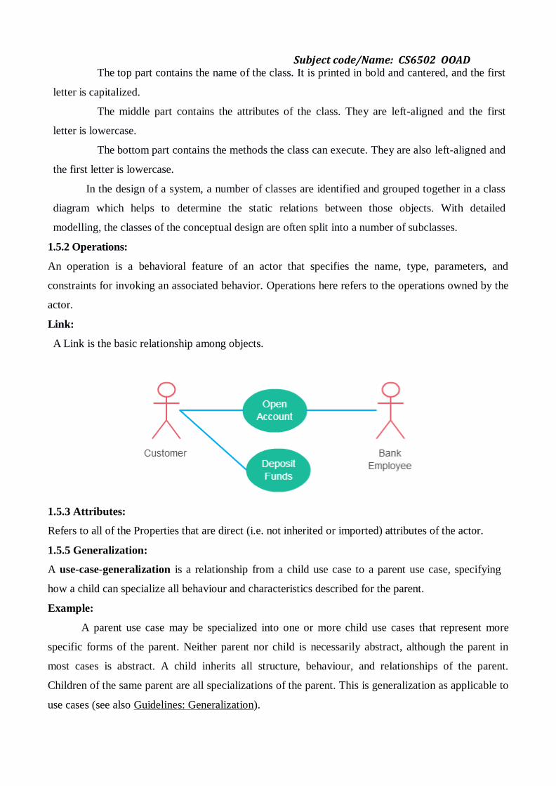
Link:
A Link is the basic relationship among objects.
1.5.3 Attributes:
Refers to all of the Properties that are direct (i.e. not inherited or imported) attributes of the actor.
1.5.5 Generalization:
A use-case-generalization is a relationship from a child use case to a parent use case, specifying
how a child can specialize all behaviour and characteristics described for the parent.
Example:
A parent use case may be specialized into one or more child use cases that represent more
specific forms of the parent. Neither parent nor child is necessarily abstract, although the parent in
most cases is abstract. A child inherits all structure, behaviour, and relationships of the parent.
Children of the same parent are all specializations of the parent. This is generalization as applicable to
use cases (see also Guidelines: Generalization).

Subject code/Name: CS6502 OOAD
Generalization is used when you find two or more use cases that have commonalities in
behaviour, structure, and purpose. When this happens, you can describe the shared parts in a new,
often abstract, use case, which is then specialized by child use cases.
Example:
1.5.5 Association:
The UML Class diagram is used to visually describe the problem domain in terms of types
of object (classes) related to each other in different ways. There are three primary inter-object
relationships: association, aggregation, and composition. Using the right relationship line is
important for placing implicit restrictions on the visibility and propagation of changes to the related
classes, matter which play major role in reducing system complexity.
Association
The most abstract way to describe static relationship between classes is using the
‗Association‘ link, which simply states that there is some kind of a link or a dependency between
two classes or more.
Weak Association
ClassA may be linked to ClassB in order to show that one of its methods includes parameter of
ClassB instance, or returns instance of ClassB.
Subject code/Name: CS6502 OOAD
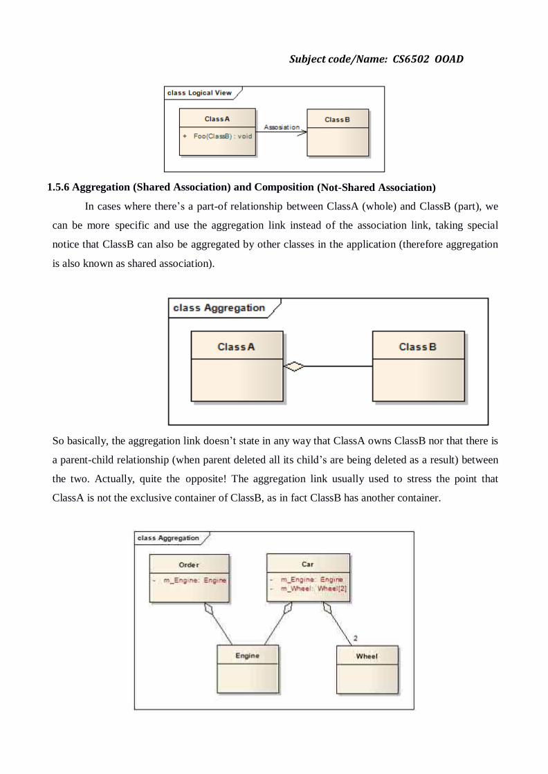
1.5.6 Aggregation (Shared Association) and Composition (Not-Shared Association)
In cases where there‘s a part-of relationship between ClassA (whole) and ClassB (part), we
can be more specific and use the aggregation link instead of the association link, taking special
notice that ClassB can also be aggregated by other classes in the application (therefore aggregation
is also known as shared association).
So basically, the aggregation link doesn‘t state in any way that ClassA owns ClassB nor that there is
a parent-child relationship (when parent deleted all its child‘s are being deleted as a result) between
the two. Actually, quite the opposite! The aggregation link usually used to stress the point that
ClassA is not the exclusive container of ClassB, as in fact ClassB has another container.
Subject code/Name: CS6502 OOAD
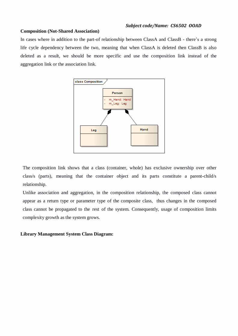
Composition (Not-Shared Association)
In cases where in addition to the part-of relationship between ClassA and ClassB - there‘s a strong
life cycle dependency between the two, meaning that when ClassA is deleted then ClassB is also
deleted as a result, we should be more specific and use the composition link instead of the
aggregation link or the association link.
The composition link shows that a class (container, whole) has exclusive ownership over other
class/s (parts), meaning that the container object and its parts constitute a parent-child/s
relationship.
Unlike association and aggregation, in the composition relationship, the composed class cannot
appear as a return type or parameter type of the composite class, thus changes in the composed
class cannot be propagated to the rest of the system. Consequently, usage of composition limits
complexity growth as the system grows.
Library Management System Class Diagram:

Subject code/Name: CS6502 OOAD
1.6 INTERACTION DIAGRAMS:
Interaction Overview Diagram is one of the thirteen types of diagrams of the Unified
Modelling Language (UML), which can picture a control flow with nodes that can
contain interaction diagrams.
The interaction overview diagram is similar to the activity diagram, in that both visualize a
sequence of activities.
The difference is that, for an interaction overview, each individual activity is pictured as a
frame which can contain a nested interaction diagrams. This makes the interaction overview
diagram useful to "deconstruct a complex scenario that would otherwise require multiple if-then-
else paths to be illustrated as a single sequence diagram".
Subject code/Name: CS6502 OOAD
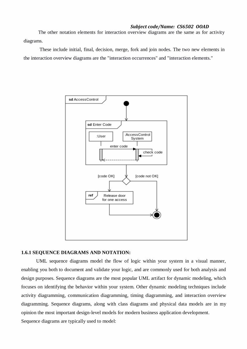
The other notation elements for interaction overview diagrams are the same as for activity
diagrams.
These include initial, final, decision, merge, fork and join nodes. The two new elements in
the interaction overview diagrams are the "interaction occurrences" and "interaction elements."
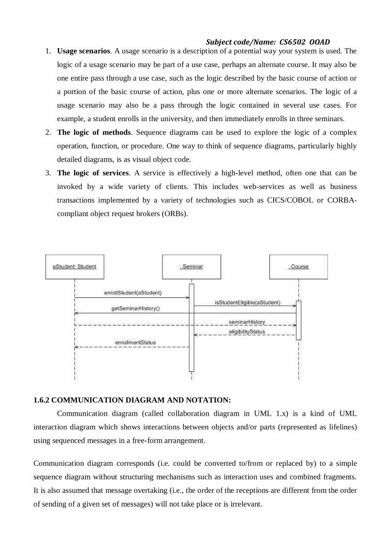
1.6.1 SEQUENCE DIAGRAMS AND NOTATION:
UML sequence diagrams model the flow of logic within your system in a visual manner,
enabling you both to document and validate your logic, and are commonly used for both analysis and
design purposes. Sequence diagrams are the most popular UML artifact for dynamic modeling, which
focuses on identifying the behavior within your system. Other dynamic modeling techniques include
activity diagramming, communication diagramming, timing diagramming, and interaction overview
diagramming. Sequence diagrams, along with class diagrams and physical data models are in my
opinion the most important design-level models for modern business application development.
Sequence diagrams are typically used to model:
Subject code/Name: CS6502 OOAD
1. Usage scenarios. A usage scenario is a description of a potential way your system is used. The
logic of a usage scenario may be part of a use case, perhaps an alternate course. It may also be
one entire pass through a use case, such as the logic described by the basic course of action or
a portion of the basic course of action, plus one or more alternate scenarios. The logic of a
usage scenario may also be a pass through the logic contained in several use cases. For
example, a student enrolls in the university, and then immediately enrolls in three seminars.
2. The logic of methods. Sequence diagrams can be used to explore the logic of a complex
operation, function, or procedure. One way to think of sequence diagrams, particularly highly
detailed diagrams, is as visual object code.
3. The logic of services. A service is effectively a high-level method, often one that can be
invoked by a wide variety of clients. This includes web-services as well as business
transactions implemented by a variety of technologies such as CICS/COBOL or CORBA-
compliant object request brokers (ORBs).
1.6.2 COMMUNICATION DIAGRAM AND NOTATION:
Communication diagram (called collaboration diagram in UML 1.x) is a kind of UML
interaction diagram which shows interactions between objects and/or parts (represented as lifelines)
using sequenced messages in a free-form arrangement.
Communication diagram corresponds (i.e. could be converted to/from or replaced by) to a simple
sequence diagram without structuring mechanisms such as interaction uses and combined fragments.
It is also assumed that message overtaking (i.e., the order of the receptions are different from the order
of sending of a given set of messages) will not take place or is irrelevant.
Subject code/Name: CS6502 OOAD
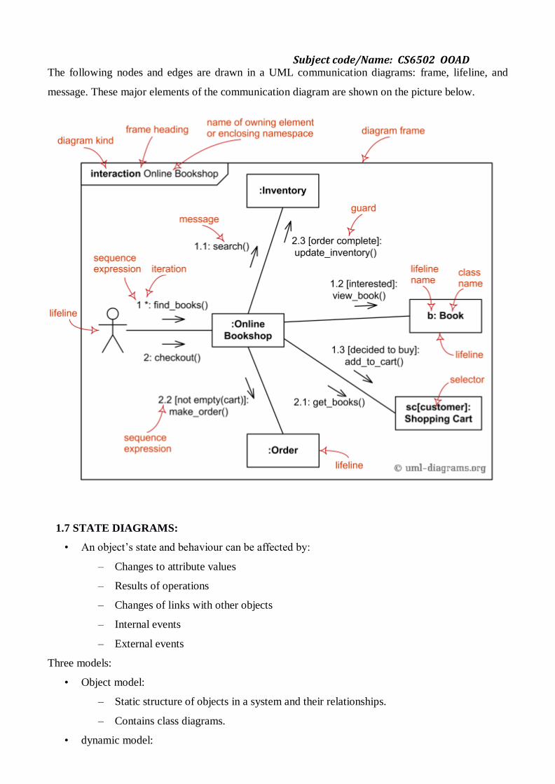
The following nodes and edges are drawn in a UML communication diagrams: frame, lifeline, and
message. These major elements of the communication diagram are shown on the picture below.
1.7 STATE DIAGRAMS:
• An object‘s state and behaviour can be affected by:
– Changes to attribute values
– Results of operations
– Changes of links with other objects
– Internal events
– External events
Three models:
• Object model:
– Static structure of objects in a system and their relationships.
– Contains class diagrams.
• dynamic model:
Subject code/Name: CS6502 OOAD
– describes aspects that change over time: state transition diagrams
• functional model:
– Use Case diagrams
1.7.1 Notation:
Initial/final States:
The initial state is denoted by a filled black circle and may be labelled with a name. The final
state is denoted by a circle with a dot inside and may also be labelled with a name.
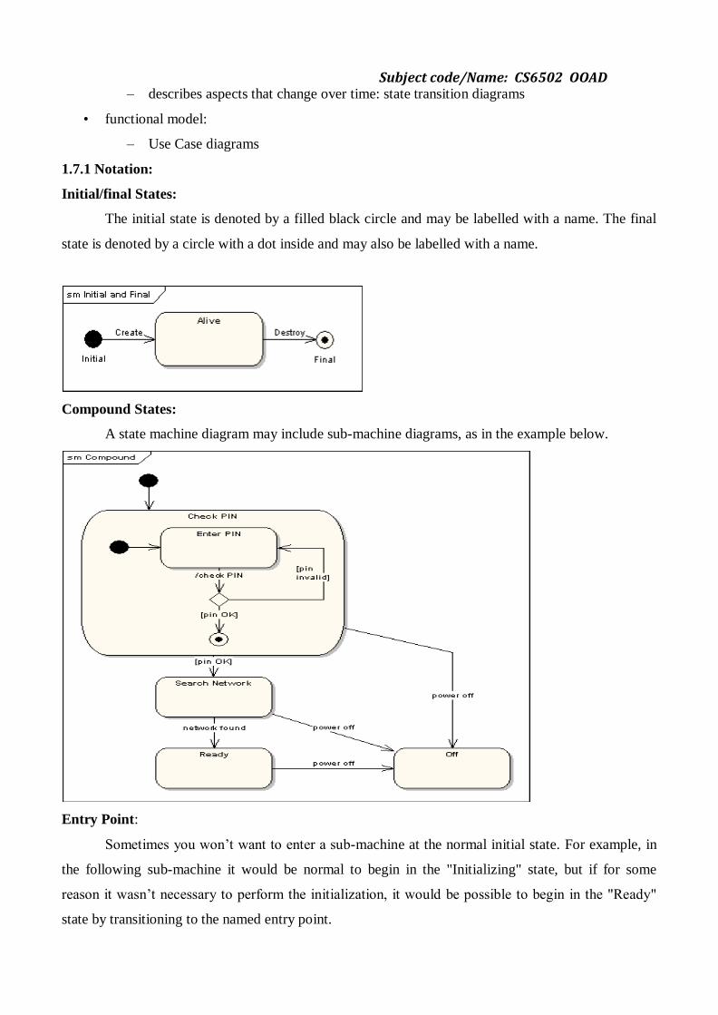
Compound States:
A state machine diagram may include sub-machine diagrams, as in the example below.
Entry Point:
Sometimes you won‘t want to enter a sub-machine at the normal initial state. For example, in
the following sub-machine it would be normal to begin in the "Initializing" state, but if for some
reason it wasn‘t necessary to perform the initialization, it would be possible to begin in the "Ready"
state by transitioning to the named entry point.

Subject code/Name: CS6502 OOAD
Exit Point:
In a similar manner to entry points, it is possible to have named alternative exit points. The
following diagram gives an example where the state executed after the main processing state depends
on which route is used to transition out of the state.
1.7.2 Events, States, Transitions:
Events:
Something that happens at a point in time
– Mouse button clicked / Signal changes
Logically ordered events - causally related
Concurrent events - causally unrelated
– do not effect each other
– there is no order between them
1-way transmission of information from one object to another
States:
A state is an abstraction of the attribute values and links of an object. Sets of values are grouped
together into a state according to properties that affect the gross behaviour of the object.
E.G. A bank is solvent or insolvent depending on whether it‘s assets exceed its liabilities.
A state corresponds to the interval between 2 events received by an object.
A state separates 2 events.
An event separates 2 states.
Subject code/Name: CS6502 OOAD
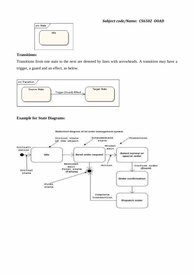
Transitions:
Transitions from one state to the next are denoted by lines with arrowheads. A transition may have a
trigger, a guard and an effect, as below.
Example for State Diagrams:
Subject code/Name: CS6502 OOAD
1.8 ACTIVITY DIAGRAMS:
Activity Diagrams consist of activities, states and transitions between activities and states.
Activity Diagrams describe
how activities are coordinated to provide a service
the events needed to achieve some operation
how the events in a single use case relate to one another
how a collection of use cases coordinate to create a workflow for anorganisation
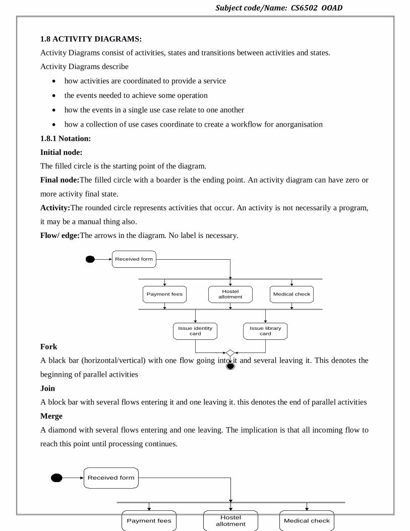
1.8.1 Notation:
Initial node:
The filled circle is the starting point of the diagram.
Final node:The filled circle with a boarder is the ending point. An activity diagram can have zero or
more activity final state.
Activity:The rounded circle represents activities that occur. An activity is not necessarily a program,
it may be a manual thing also.
Flow/ edge:The arrows in the diagram. No label is necessary.
Fork
A black bar (horizontal/vertical) with one flow going into it and several leaving it. This denotes the
beginning of parallel activities
Join
A block bar with several flows entering it and one leaving it. this denotes the end of parallel activities
Merge
A diamond with several flows entering and one leaving. The implication is that all incoming flow to
reach this point until processing continues.
Received form
Payment feesHostel
allotment
Issue identity
card
Medical check
Issue library
card
Received form
Payment feesHostel
allotment
Issue identity
card
Medical check
Issue library
card
Subject code/Name: CS6502 OOAD
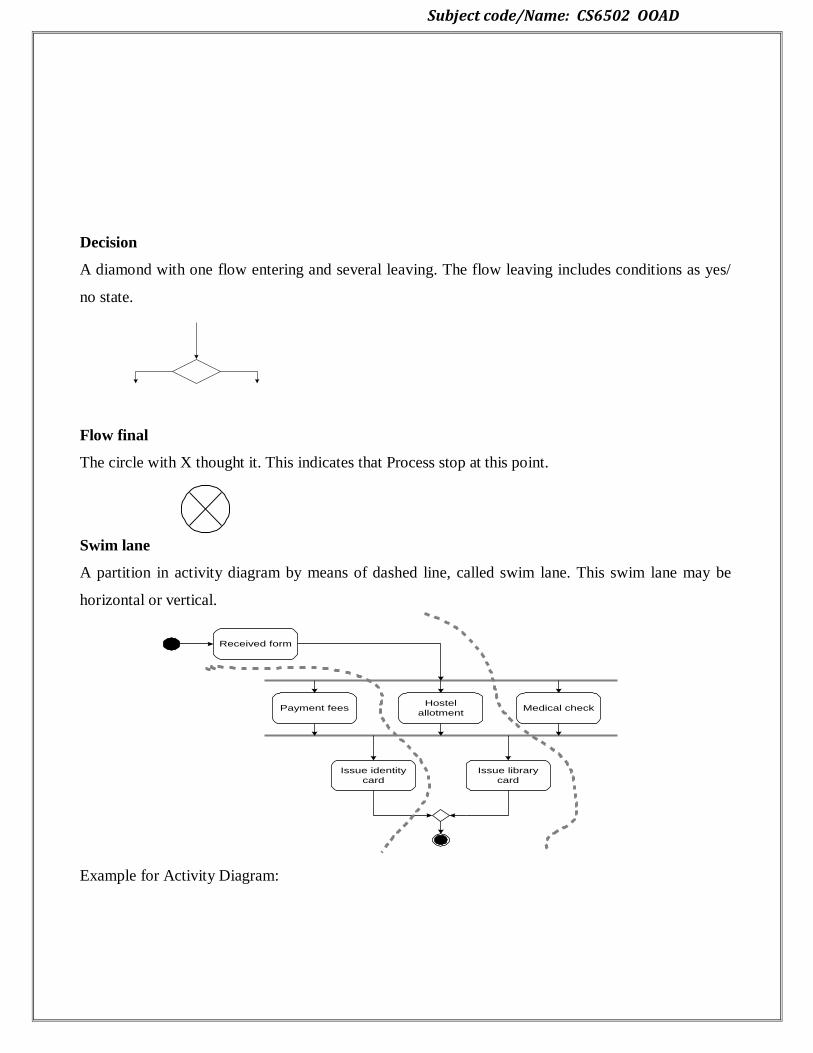
Decision
A diamond with one flow entering and several leaving. The flow leaving includes conditions as yes/
no state.
Flow final
The circle with X thought it. This indicates that Process stop at this point.
Swim lane
A partition in activity diagram by means of dashed line, called swim lane. This swim lane may be
horizontal or vertical.
Example for Activity Diagram:
Received form
Payment feesHostel
allotment
Issue identity
card
Medical check
Issue library
card

Subject code/Name: CS6502 OOAD
1.9 PACKAGE DIAGRAMS:
Package diagram is UML structure diagram which shows packages and dependencies between the
packages.
Model diagrams allow to show different views of a system, for example, as multi-layered (aka multi-
tiered) application - multi-layered application model.
1.9.1 Notations:
Subject code/Name: CS6502 OOAD
The following nodes and edges are typically drawn in a package diagram: package, packageable
element, dependency, element import, package import, package merge.
Package is a namespace used to group together elements that are semantically related and might
change together. It is a general purpose mechanism to organize elements into groups to provide better
structure for system model.
Owned members of a package should all be packageable elements. If a package is removed from a
model, so are all the elements owned by the package. Package by itself is packageable element, so
any package could be also a member of other packages.
Because package is a namespace, elements of related or the same type should have unique names
within the enclosing package. Different types of elements are allowed to have the same name.
As a namespace, a package can import either individual members of other packages or all the
members of other packages. Package can also be merged with other packages.
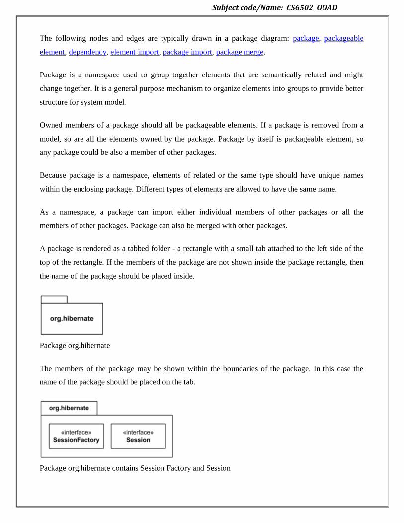
A package is rendered as a tabbed folder - a rectangle with a small tab attached to the left side of the
top of the rectangle. If the members of the package are not shown inside the package rectangle, then
the name of the package should be placed inside.
Package org.hibernate
The members of the package may be shown within the boundaries of the package. In this case the
name of the package should be placed on the tab.
Package org.hibernate contains Session Factory and Session

Subject code/Name: CS6502 OOAD
A diagram showing a package with content is allowed to show only a subset of the contained
elements according to some criterion.
Members of the package may be shown outside of the package by branching lines from the package
to the members. A plus sign (+) within a circle is drawn at the end attached to the namespace
(package). This notation for packages is semantically equivalent to composition (which is shown
using solid diamond.)
Package org.hibernate contains interfaces Session Factory and Session.
The elements that can be referred to within a package using non-qualified names are:
owned elements,
imported elements, and
Elements in enclosing (outer) namespaces.
Owned and imported elements may have a visibility that determines whether they are available
outside the package.
If an element that is owned by a package has visibility, it could be only public or private visibility.
Protected or package visibility is not allowed. The visibility of a package element may be indicated
by preceding the name of the element by a visibility symbol ("+" for public and "-" for private).
All elements of Library Domain package are public except for Account

Subject code/Name: CS6502 OOAD
The public elements of a package are always accessible outside the package through the use of
qualified names.
Package can be used as a template for other packages. Inconsistently calls it both package template
and template package.
Packageable element can be used as a template parameter. A package template parameter may refer
to any element owned or used by the package template, or templates nested within it.
A package may be bound to one or more template packages. When several bindings are applied the
result of bindings is produced by taking the intermediate results and merging them into the combined
result using package merge.
1.10 COMPONENT DIAGRAMS:
Component diagrams are different in terms of nature and behavior. Component diagrams are used to
model the physical aspects of a system. Now the question is, what are these physical aspects?

Subject code/Name: CS6502 OOAD
Physical aspects are the elements such as executables, libraries, files, documents, etc. which reside in
a node.
Component diagrams are used to visualize the organization and relationships among components in a
system. These diagrams are also used to make executable systems.
1.10.1 Notation:
Component diagram is a special kind of diagram in UML. The purpose is also different from all other
diagrams discussed so far. It does not describe the functionality of the system but it describes the
components used to make those functionalities.
Thus from that point of view, component diagrams are used to visualize the physical components in a
system. These components are libraries, packages, files, etc.
Component diagrams can also be described as a static implementation view of a system. Static
implementation represents the organization of the components at a particular moment.
A single component diagram cannot represent the entire system but a collection of diagrams is used
to represent the whole.
The purpose of the component diagram can be summarized as
Visualize the components of a system.
Construct executables by using forward and reverse engineering.
Describe the organization and relationships of the components.
How to Draw a Component Diagram?
Component diagrams are used to describe the physical artifacts of a system. This artifact includes
files, executables, libraries, etc
The purpose of this diagram is different. Component diagrams are used during the implementation
phase of an application. However, it is prepared well in advance to visualize the implementation
details.
Subject code/Name: CS6502 OOAD
Initially, the system is designed using different UML diagrams and then when the artifacts are ready,
component diagrams are used to get an idea of the implementation.
This diagram is very important as without it the application cannot be implemented efficiently. A
well-prepared component diagram is also important for other aspects such as application
performance, maintenance, etc.
Before drawing a component diagram, the following artifacts are to be identified clearly −
Files used in the system.
Libraries and other artifacts relevant to the application.
Relationships among the artifacts.
After identifying the artifacts, the following points need to be kept in mind.
Use a meaningful name to identify the component for which the diagram is to be drawn.
Prepare a mental layout before producing the using tools.
Use notes for clarifying important points.
Following is a component diagram for order management system. Here, the artifacts are files. The
diagram shows the files in the application and their relationships. In actual, the component diagram
also contains dlls, libraries, folders, etc.
In the following diagram, four files are identified and their relationships are produced. Component
diagram cannot be matched directly with other UML diagrams discussed so far as it is drawn for
completely different purpose.
The following component diagram has been drawn considering all the points mentioned above.

Subject code/Name: CS6502 OOAD
Where to Use Component Diagrams?
We have already described that component diagrams are used to visualize the static implementation
view of a system. Component diagrams are special type of UML diagrams used for different
purposes.
These diagrams show the physical components of a system. To clarify it, we can say that component
diagrams describe the organization of the components in a system.
Organization can be further described as the location of the components in a system. These
components are organized in a special way to meet the system requirements.
As we have already discussed, those components are libraries, files, executables, etc. Before
implementing the application, these components are to be organized. This component organization is
also designed separately as a part of project execution.
Component diagrams are very important from implementation perspective. Thus, the implementation
team of an application should have a proper knowledge of the component details
Component diagrams can be used to −
Model the components of a system.

Subject code/Name: CS6502 OOAD
Model the database schema.
Model the executables of an application.
Model the system's source code.
1.11 DEPLOYMENT DIAGRAMS:
Deployment diagrams are used to visualize the topology of the physical components of a system,
where the software components are deployed.
Deployment diagrams are used to describe the static deployment view of a system. Deployment
diagrams consist of nodes and their relationships.
1.11.1 Notation:
The term Deployment itself describes the purpose of the diagram. Deployment diagrams are used for
describing the hardware components, where software components are deployed. Component
diagrams and deployment diagrams are closely related.
Component diagrams are used to describe the components and deployment diagrams shows how they
are deployed in hardware.
UML is mainly designed to focus on the software artifacts of a system. However, these two diagrams
are special diagrams used to focus on software and hardware components.
Most of the UML diagrams are used to handle logical components but deployment diagrams are
made to focus on the hardware topology of a system. Deployment diagrams are used by the system
engineers.
The purpose of deployment diagrams can be described as −
Visualize the hardware topology of a system.
Describe the hardware components used to deploy software components.
Describe the runtime processing nodes.
Subject code/Name: CS6502 OOAD
How to Draw a Deployment Diagram?
Deployment diagram represents the deployment view of a system. It is related to the component
diagram because the components are deployed using the deployment diagrams. A deployment
diagram consists of nodes. Nodes are nothing but physical hardware used to deploy the application.
Deployment diagrams are useful for system engineers. An efficient deployment diagram is very
important as it controls the following parameters −
Performance
Scalability
Maintainability
Portability
Before drawing a deployment diagram, the following artifacts should be identified −
Nodes
Relationships among nodes
Following is a sample deployment diagram to provide an idea of the deployment view of order
management system. Here, we have shown nodes as −
Monitor
Modem
Caching server
Server
The application is assumed to be a web-based application, which is deployed in a clustered
environment using server 1, server 2, and server 3. The user connects to the application using the
Internet. The control flows from the caching server to the clustered environment.
The following deployment diagram has been drawn considering all the points mentioned above.

Subject code/Name: CS6502 OOAD
Where to Use Deployment Diagrams?
Deployment diagrams are mainly used by system engineers. These diagrams are used to describe the
physical components (hardware), their distribution, and association.
Deployment diagrams can be visualized as the hardware components/nodes on which the software
components reside.
Software applications are developed to model complex business processes. Efficient software
applications are not sufficient to meet the business requirements. Business requirements can be
described as the need to support the increasing number of users, quick response time, etc.
To meet these types of requirements, hardware components should be designed efficiently and in a
cost-effective way.
Now-a-days software applications are very complex in nature. Software applications can be
standalone, web-based, distributed, mainframe-based and many more. Hence, it is very important to
design the hardware components efficiently.
Deployment diagrams can be used −
Subject code/Name: CS6502 OOAD
To model the hardware topology of a system.
To model the embedded system.
To model the hardware details for a client/server system.
To model the hardware details of a distributed application.
For Forward and Reverse engineering.
UNIT II
DESIGN PATTERNS
2.1 GRASP: Designing objects with responsibilities
General Responsibility Assignment Software Patterns (or Principles), abbreviated
GRASP, consists of guidelines for assigning responsibility to classes and objects in object-oriented
design.
The different patterns and principles used in GRASP are: Controller, Creator,
Indirection, Information Expert, High Cohesion, Low Coupling, Polymorphism, Protected
Variations, and Pure Fabrication.
All these patterns answer some software problem, and in almost every case these
problems are common to almost every software development project. These techniques have
not been invented to create new ways of working, but to better document and standardize old,
tried-and- tested programming principles in object-oriented design.
Computer scientist Craig Larman states that "the critical design tool for software
development is a mind well educated in design principles. It is not the UML or any
other technology."[1] Thus, GRASP is really a mental toolset, a learning aid to help in the
design of object-oriented software.
2.2 CREATOR:
Creation of objects is one of the most common activities in an object-oriented system.
Which class is responsible for creating objects is a fundamental property of the relationship
between objects of particular classes.
2.2.1 Implementation:
In general, a class B should be responsible for creating instances of class A if one, or
preferably more, of the following apply:
Instances of B contain or compositely aggregate instances of
A Instances of B record instances of A
Instances of B closely use instances of A
Subject code/Name: CS6502 OOAD
Instances of B have the initializing information for instances of A and pass it on creation.
"Factory pattern" redirects here. For the GoF design patterns using factories, see factory
method pattern and abstract factory pattern.
In object-oriented programming, a factory is an object for creating other objects – formally
a factory is simply an object that returns an object from some method call, which is assumed to
be "new".
More broadly, a subroutine that returns a "new" object may be referred to as a "factory",
as in factory method or factory function. This is a basic concept in OOP, and forms the basis
for a number of related software design patterns.
Object creation:
Factory objects are used in situations where getting hold of an object of a particular kind is
a more complex process than simply creating a new object, notably if complex allocation
or initialization is desired.
Some of the processes required in the creation of an object include determining which
object to create, managing the lifetime of the object, and managing specialized build-up and
tear-down concerns of the object.
The factory object might decide to create the object's class (if applicable) dynamically,
return it from an object pool, do complex configuration on the object, or other things. Similarly,
using this definition, a singleton implemented by the singleton pattern is a formal factory – it
returns an object, but does not create new objects beyond the single instance.
The simplest example of a factory is a simple factory function, which just invokes a
constructor and returns the result. In Python, a factory function f that instantiates a class A can
be implemented as:
def f():
return A()
A simple factory function implementing the singleton pattern is:
def f():
if f.obj is
None: f.obj =
A() return f.obj
f.obj = None
Factories are used in various design patterns, specifically in creational patterns. Specific
recipes have been developed to implement them in many languages.
Subject code/Name: CS6502 OOAD
For example, several "GoF patterns", like the "Factory method pattern", the "Builder" or
even the "Singleton" are implementations of this concept. The "Abstract factory pattern" instead is
a method to build collections of factories.
In some design patterns, a factory object has a method for every kind of object it is
capable of creating. These methods optionally accept parameters defining how the object is
created, and then return the created object.
Applications
Factory objects are common in toolkits and frameworks where library code needs to
create objects of types which may be subclassed by applications using the framework. They are
also used in test-driven development to allow classes to be put under test.
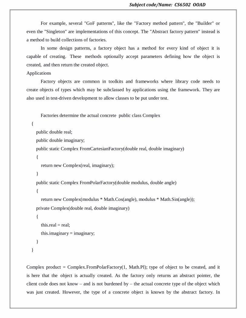
Factories determine the actual concrete public class Complex
{
public double real;
public double imaginary;
public static Complex FromCartesianFactory(double real, double imaginary)
{
return new Complex(real, imaginary);
}
public static Complex FromPolarFactory(double modulus, double angle)
{
return new Complex(modulus * Math.Cos(angle), modulus * Math.Sin(angle));
private Complex(double real, double imaginary)
{
this.real = real;
this.imaginary = imaginary;
}
}
Complex product = Complex.FromPolarFactory(1, Math.PI); type of object to be created, and it
is here that the object is actually created. As the factory only returns an abstract pointer, the
client code does not know – and is not burdened by – the actual concrete type of the object which
was just created. However, the type of a concrete object is known by the abstract factory. In

Subject code/Name: CS6502 OOAD
particular, this means:
The client code has no knowledge whatsoever of the concrete type, not needing to
include any header files or class declarations relating to the concrete type. The client code deals
only with the abstract type. Objects of a concrete type are indeed created by the factory, but the
client code accesses such objects only through their abstract interface.
Adding new concrete types is done by modifying the client code to use a different
factory, a modification which is typically one line in one file. This is significantly easier than
modifying the client code to instantiate a new type, which would require changing every
location in the code where a new object is created.
public class Complex
{
public double real;
public double imaginary;
public static Complex FromCartesianFactory(double real, double imaginary)
{
return new Complex(real, imaginary);
}
public static Complex FromPolarFactory(double modulus, double angle)
{
return new Complex(modulus * Math.Cos(angle), modulus * Math.Sin(angle));
}
private Complex(double real, double imaginary)
{
this.real = real;
this.imaginary = imaginary;
}
}
Complex product = Complex.FromPolarFactory(1, Math.PI);
2.3 INFORMATION EXPERT:
GRASP Patterns – Information Expert

Subject code/Name: CS6502 OOAD
Name: Information Expert
Problem: What is a general principle of assigning responsibility to objects?
Solution: Assign a responsibility to the class that has the information needed to fulfil it
2.3.1 Implementation:
In the NextGen application, some class needs to know the grand total of a
sale
Discussion:
•Information Expert is frequently used in the assignment of responsibilities; it is a basic guiding
Principles used continuously in object
design.
•The fulfilment of a responsibility often requires information spread across different classes of
objects.
• Expert usually leads to designs where a software object does those operations that are
normally
Done to the inanimate real-world thing it represents.
•The Information Expert
pattern
–like many things in OO
– has a real
-world analogy.
Contraindications:
• There are situations where a solution suggested by Expert is undesirable, usually because of
Problems in coupling and
cohesion
•Ex. who should be responsible for saving a Sale in a
database?
2.4. LOW COUPLING:
Name: Low Coupling
Problem: How to support low dependency, low change impact, and increased reuse?
Solution: Assign a responsibility so that coupling remains low
2.4.1 Implementation:
Assume a need to create a Payment instance and associate it with the Sale, who should be
responsible for this?
Subject code/Name: CS6502 OOAD
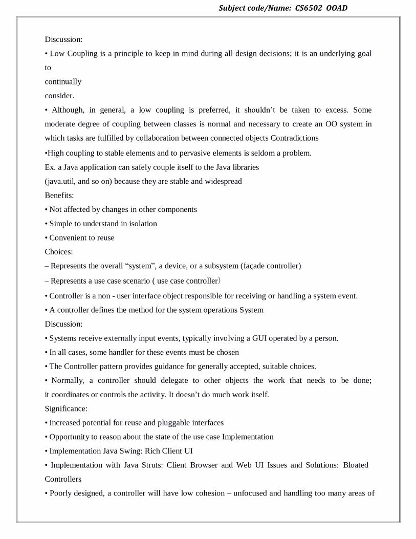
Discussion:
• Low Coupling is a principle to keep in mind during all design decisions; it is an underlying goal
to
continually
consider.
• Although, in general, a low coupling is preferred, it shouldn‘t be taken to excess. Some
moderate degree of coupling between classes is normal and necessary to create an OO system in
which tasks are fulfilled by collaboration between connected objects Contradictions
•High coupling to stable elements and to pervasive elements is seldom a problem.
Ex. a Java application can safely couple itself to the Java libraries
(java.util, and so on) because they are stable and widespread
Benefits:
• Not affected by changes in other components
• Simple to understand in isolation
• Convenient to reuse
Choices:
– Represents the overall ―system‖, a device, or a subsystem (façade controller)
– Represents a use case scenario ( use case controller)
• Controller is a non - user interface object responsible for receiving or handling a system event.
• A controller defines the method for the system operations System
Discussion:
• Systems receive externally input events, typically involving a GUI operated by a person.
• In all cases, some handler for these events must be chosen
• The Controller pattern provides guidance for generally accepted, suitable choices.
• Normally, a controller should delegate to other objects the work that needs to be done;
it coordinates or controls the activity. It doesn‘t do much work itself.
Significance:
• Increased potential for reuse and pluggable interfaces
• Opportunity to reason about the state of the use case Implementation
• Implementation Java Swing: Rich Client UI
• Implementation with Java Struts: Client Browser and Web UI Issues and Solutions: Bloated
Controllers
• Poorly designed, a controller will have low cohesion – unfocused and handling too many areas of
Subject code/Name: CS6502 OOAD
responsibility
• Signs of bloating.
2.5 GRASP – HIGH COHESION
• Concept – Cohesion:
– Cohesion is a measure of ―relatedness‖.
– High Cohesion says elements are strongly related to one another.
– Low Cohesion says elements are not strongly related to one another.
2.5.1 Implementation:
• System level: ATM with a use case (function) called ―Teller Reports‖.
• Class level: A Student class with a method called ―getDrivingRecord ().
• Method level: Methods with the word ―And‖ or ―Or‖ in them.
• Also applies to subsystem (package) level, component level, etc.Designs with low cohesion are
Difficult to maintain and reuse.
– One of the fundamental goals of an effective design is to achieve higH cohesion with low
coupling (which we will see later)
Problem: How do you keep complexity manageable?
•Solution: Assign responsibility so that cohesion remains high.
• Mechanics: Look for classes with too-few or disconnected methods. Look for methods that do
to much (hint: method name)Rework your design as needed.
High Cohesion is an evaluative pattern that attempts to keep objects appropriately
focused, manageable and understandable.
High cohesion is generally used in support of Low Coupling. High cohesion means that
the responsibilities of a given element are strongly related and highly focused. Breaking programs
into classes and subsystems is an example of activities that increase the cohesive properties of a
system.
Alternatively, low cohesion is a situation in which a given element has too many
unrelated responsibilities. Elements with low cohesion often suffer from being hard to
comprehend, hard to reuse, hard to maintain and averse to change.
The Indirection pattern supports low coupling (and reuse potential) between two
elements by assigning the responsibility of mediation between them to an intermediate object. An
example of this is the introduction of a controller component for mediation between data
(model) and its representation (view) in the Model-view-controller pattern.
Subject code/Name: CS6502 OOAD
Information Expert
Information Expert (also Expert or the Expert Principle) is a principle used to determine
where to delegate responsibilities. These responsibilities include methods, computed fields, and
so on.
Using the principle of Information Expert, a general approach to assigning responsibilities
is to look at a given responsibility, determine the information needed to fulfill it, and then
determine where that information is stored.
Information Expert will lead to placing the responsibility on the class with the
most information required to fulfill it.Low Coupling
Low Coupling is an evaluative pattern, which dictates how to assign responsibilities to support:
lower dependency between the classes,
change in one class having lower impact on other
classes, higher reuse potential.
2.6 CONTROLLER:
The Controller pattern assigns the responsibility of dealing with system events to a non-UI
class that represents the overall system or a use case scenario. A Controller object is a non-user
interface object responsible for receiving or handling a system event.
A use case controller should be used to deal with all system events of a use case, and may
be used for more than one use case (for instance, for use cases Create User and Delete User, one
can have a single UserController, instead of two separate use case controllers).
It is defined as the first object beyond the UI layer that receives and coordinates ("controls")
a system
operation.
The controller should delegate the work that needs to be done to other objects;
it coordinates or controls the activity. It should not do much work itself.
The GRASP Controller can be thought of as being a part of the Application/Service
layer (assuming that the application has made an explicit distinction between the
application/service layer and the domain layer) in an object-oriented system with Common layers
in an information system logical architecture.
The front controller design pattern is used to provide a centralized request handling mechanism so
that all requests will be handled by a single handler. This handler can do the authentication/

Subject code/Name: CS6502 OOAD
authorization/ logging or tracking of request and then pass the requests to corresponding handlers.
Following are the entities of this type of design pattern.
Front Controller - Single handler for all kinds of requests coming to the application (either
web based/ desktop based).
Dispatcher - Front Controller may use a dispatcher object which can dispatch the request to
corresponding specific handler.
View - Views are the object for which the requests are made.
2.6.1 Implementation:
We are going to create a Front Controller and Dispatcher to act as Front Controller and Dispatcher
correspondingly. Home View and Student View represent various views for which requests can come
to front controller.
Front Controller Pattern Demo, our demo class, will use Front Controller to demonstrate Front
Controller Design Pattern.
Step 1
Create Views.
HomeView.java
public class HomeView {

Subject code/Name: CS6502 OOAD
public void show(){
System.out.println("Displaying Home Page");
}
}
StudentView.java
public class StudentView {
public void show(){
System.out.println("Displaying Student Page");
}
}
Step 2
Create Dispatcher.
Dispatcher.java
public class Dispatcher {
private StudentView studentView;
private HomeView homeView;
public Dispatcher(){
studentView = new StudentView();
homeView = new HomeView();
}
public void dispatch(String request){
if(request.equalsIgnoreCase("STUDENT")){
studentView.show();
}
else{
homeView.show();
}
Subject code/Name: CS6502 OOAD
}
}
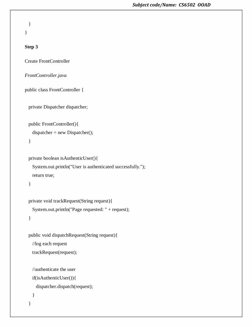
Step 3
Create FrontController
FrontController.java
public class FrontController {
private Dispatcher dispatcher;
public FrontController(){
dispatcher = new Dispatcher();
}
private boolean isAuthenticUser(){
System.out.println("User is authenticated successfully.");
return true;
}
private void trackRequest(String request){
System.out.println("Page requested: " + request);
}
public void dispatchRequest(String request){
//log each request
trackRequest(request);
//authenticate the user
if(isAuthenticUser()){
dispatcher.dispatch(request);
}
}

Subject code/Name: CS6502 OOAD
}
Step 4
Use the FrontController to demonstrate Front Controller Design Pattern.
FrontControllerPatternDemo.java
public class FrontControllerPatternDemo {
public static void main(String[] args) {
FrontController frontController = new FrontController();
frontController.dispatchRequest("HOME");
frontController.dispatchRequest("STUDENT");
}
}
Step 5
Verify the output.
Page requested: HOME
User is authenticated successfully.
Displaying Home Page
Page requested: STUDENT
User is authenticated successfully.
Displaying Student Page
2.7. DESIGN PATTERNS:
Design patterns represent the best practices used by experienced object-oriented
software developers. Design patterns are solutions to general problems that software
developers faced during software development. These solutions were obtained by trial and
error by numerous software developers over quite a substantial period of time.
Types of Design Patterns:
As per the design pattern reference book Design Patterns - Elements of Reusable Object-Oriented
Software , there are 23 design patterns which can be classified in three categories: Creational,

Subject code/Name: CS6502 OOAD
Structural and Behavioral patterns. We'll also discuss another category of design pattern: J2EE design
patterns.
Creational Patterns
Structural Patterns
Behavioural Patterns
2.7.1 CREATIONAL PATTERNS:
In software engineering, creational design patterns are design patterns that deal with object
creation mechanisms, trying to create objects in a manner suitable to the situation. The basic form of
object creation could result in design problems or added complexity to the design. Creational design
patterns solve this problem by somehow controlling this object creation.
Abstract Factory
Creates an instance of several families of classes
Builder
Separates object construction from its representation
Factory Method
Creates an instance of several derived classes
Object Pool
Avoid expensive acquisition and release of resources by recycling objects that are no longer in
use
Prototype
A fully initialized instance to be copied or cloned
Subject code/Name: CS6502 OOAD
Singleton
A class of which only a single instance can exist.
2.7.2 FACTORY METHOD:
Intent
Define an interface for creating an object, but let subclasses decide which class to instantiate.
Factory Method lets a class defer instantiation to subclasses.
Defining a "virtual" constructor.
The new operator considered harmful.
Problem
A framework needs to standardize the architectural model for a range of applications, but allow for
individual applications to define their own domain objects and provide for their instantiation.
Discussion
Factory Method is to creating objects as Template Method is to implementing an algorithm. A
superclass specifies all standard and generic behavior (using pure virtual "placeholders" for creation
steps), and then delegates the creation details to subclasses that are supplied by the client.
Factory Method makes a design more customizable and only a little more complicated. Other design
patterns require new classes, whereas Factory Method only requires a new operation.
People often use Factory Method as the standard way to create objects; but it isn't necessary if: the
class that's instantiated never changes, or instantiation takes place in an operation that subclasses can
easily override (such as an initialization operation).
Factory Method is similar to Abstract Factory but without the emphasis on families.
Factory Methods are routinely specified by an architectural framework, and then implemented by the
user of the framework.
2.7.2.1 IMPLEMENTATION:
The implementation of Factory Method discussed in the Gang of Four (below) largely overlaps with
that of Abstract Factory. For that reason, the presentation in this chapter focuses on the approach that
has become popular since.

Subject code/Name: CS6502 OOAD
2.8 STRUCTURAL PATTERNS
In Software Engineering, Structural Design Patterns are Design Patterns that ease the design by
identifying a simple way to realize relationships between entities.
Adapter
Match interfaces of different classes
Bridge
separates an object's interface from its implementation
Composite
A tree structure of simple and composite objects
Decorator
Add responsibilities to objects dynamically
Facade
A single class that represents an entire subsystem
Flyweight
A fine-grained instance used for efficient sharing
Private Class Data
Restricts accessory/matador access
Proxy
An object representing another object
Subject code/Name: CS6502 OOAD
2.8.1 ADAPTER PATTERNS:
Intent
Convert the interface of a class into another interface clients expect. Adapter lets classes work
together that couldn't otherwise because of incompatible interfaces.
Wrap an existing class with a new interface.
Impedance match an old component to a new system
Problem
An "off the shelf" component offers compelling functionality that you would like to reuse, but its
"view of the world" is not compatible with the philosophy and architecture of the system currently
being developed.
Discussion
Reuse has always been painful and elusive. One reason has been the tribulation of designing
something new, while reusing something old. There is always something not quite right between the
old and the new. It may be physical dimensions or misalignment. It may be timing or
synchronization. It may be unfortunate assumptions or competing standards.
It is like the problem of inserting a new three-prong electrical plug in an old two-prong wall outlet –
some kind of adapter or intermediary is necessary.
Adapter is about creating an intermediary abstraction that translates, or maps, the old component to
the new system. Clients call methods on the Adapter object which redirects them into calls to the
legacy component. This strategy can be implemented either with inheritance or with aggregation.
Adapter functions as a wrapper or modifier of an existing class. It provides a different or translated
view of that class.
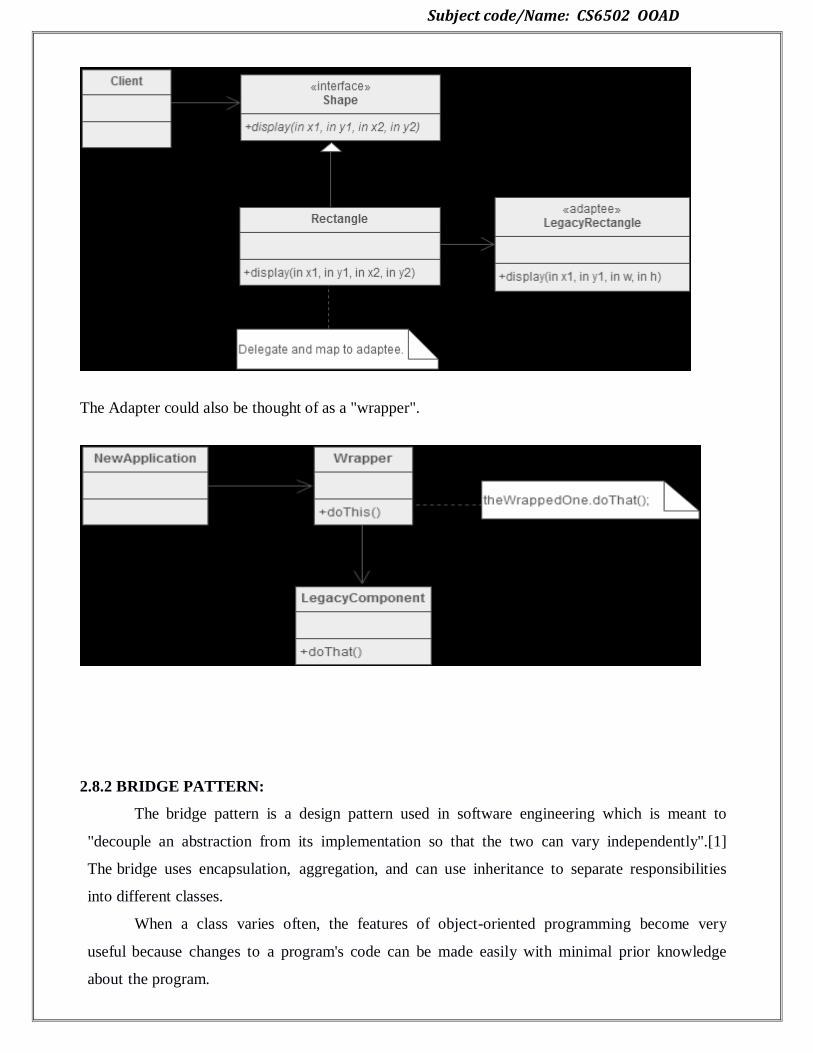
2.8.1.1 Implementation:
Below, a legacy Rectangle component's display() method expects to receive "x, y, w, h" parameters.
But the client wants to pass "upper left x and y" and "lower right x and y". This incongruity can be
reconciled by adding an additional level of indirection – i.e. an Adapter object.
Subject code/Name: CS6502 OOAD
The Adapter could also be thought of as a "wrapper".
2.8.2 BRIDGE PATTERN:
The bridge pattern is a design pattern used in software engineering which is meant to
"decouple an abstraction from its implementation so that the two can vary independently".[1]
The bridge uses encapsulation, aggregation, and can use inheritance to separate responsibilities
into different classes.
When a class varies often, the features of object-oriented programming become very
useful because changes to a program's code can be made easily with minimal prior knowledge
about the program.
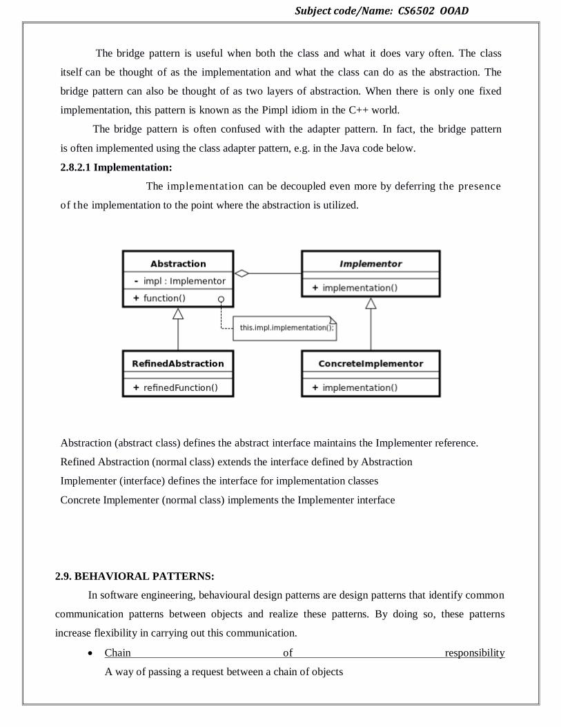
Subject code/Name: CS6502 OOAD
The bridge pattern is useful when both the class and what it does vary often. The class
itself can be thought of as the implementation and what the class can do as the abstraction. The
bridge pattern can also be thought of as two layers of abstraction. When there is only one fixed
implementation, this pattern is known as the Pimpl idiom in the C++ world.
The bridge pattern is often confused with the adapter pattern. In fact, the bridge pattern
is often implemented using the class adapter pattern, e.g. in the Java code below.
2.8.2.1 Implementation:
The implementation can be decoupled even more by deferring the presence
of the implementation to the point where the abstraction is utilized.
Abstraction (abstract class) defines the abstract interface maintains the Implementer reference.
Refined Abstraction (normal class) extends the interface defined by Abstraction
Implementer (interface) defines the interface for implementation classes
Concrete Implementer (normal class) implements the Implementer interface
2.9. BEHAVIORAL PATTERNS:
In software engineering, behavioural design patterns are design patterns that identify common
communication patterns between objects and realize these patterns. By doing so, these patterns
increase flexibility in carrying out this communication.
Chain of responsibility
A way of passing a request between a chain of objects

Subject code/Name: CS6502 OOAD
Command
Encapsulate a command request as an object
Interpreter
A way to include language elements in a program
Iterator
Sequentially access the elements of a collection
Mediator
Defines simplified communication between classes
Memento
Capture and restore an object's internal state
Null Object
Designed to act as a default value of an object
Observer
A way of notifying change to a number of classes
State
Alter an object's behaviour when its state changes
Strategy
Encapsulates an algorithm inside a class
Template method
Defer the exact steps of an algorithm to a subclass
Visitor
Defines a new operation to a class without change
2.9.1 OBSERVER:

Subject code/Name: CS6502 OOAD
2.9.1.1 Implementation:
Define an object that is the "keeper" of the data model and/or business logic (the
Subject). Delegate all ―view" functionality to decoupled and distinct Observer objects. Observers
register themselves with the Subject as they are created.
Whenever the Subject changes, it broadcasts to all registered Observers that it has
changed, and each Observer queries the Subject for that subset of the Subject's state that it is
responsible for monitoring.
This allows the number and "type" of "view" objects to be configured dynamically,
instead of being statically specified at compile-time.
The protocol described above specifies a "pull" interaction model. Instead of the Subject
"pushing" what has changed to all Observers, each Observer is responsible for "pulling"
its particular "window of interest" from the Subject. The "push" model compromises reuse, while
the "pull" model is less efficient.
Issues that are discussed, but left to the discretion of the designer, include: implementing
event compression (only sending a single change broadcast after a series of consecutive changes
has occurred), having a single Observer monitoring multiple Subjects, and ensuring that a
Subject notify its Observers when it is about to go away.
The Observer pattern captures the lion's share of the Model-View-Controller architecture
that has been a part of the Smalltalk community for years.
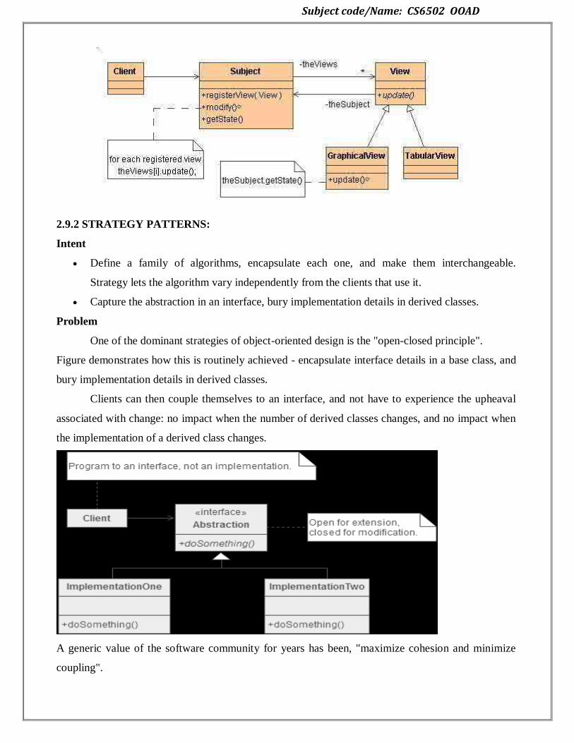
Subject code/Name: CS6502 OOAD
2.9.2 STRATEGY PATTERNS:
Intent
Define a family of algorithms, encapsulate each one, and make them interchangeable.
Strategy lets the algorithm vary independently from the clients that use it.
Capture the abstraction in an interface, bury implementation details in derived classes.
Problem
One of the dominant strategies of object-oriented design is the "open-closed principle".
Figure demonstrates how this is routinely achieved - encapsulate interface details in a base class, and
bury implementation details in derived classes.
Clients can then couple themselves to an interface, and not have to experience the upheaval
associated with change: no impact when the number of derived classes changes, and no impact when
the implementation of a derived class changes.
A generic value of the software community for years has been, "maximize cohesion and minimize
coupling".
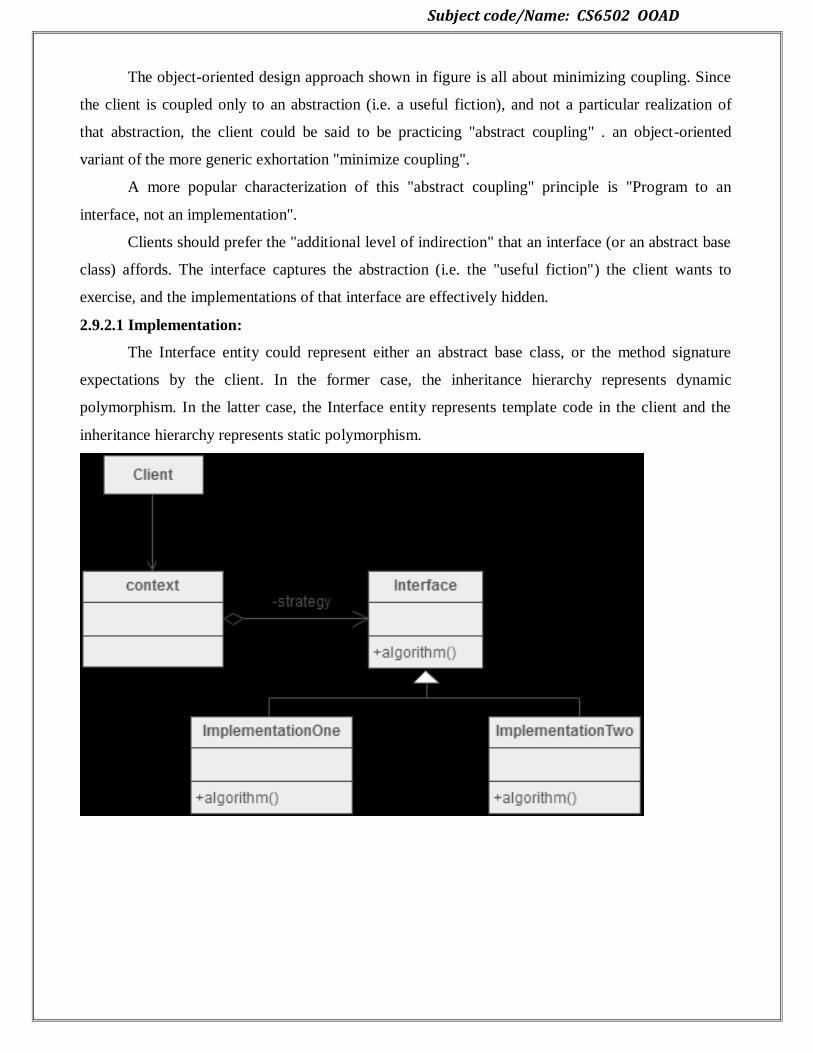
Subject code/Name: CS6502 OOAD
The object-oriented design approach shown in figure is all about minimizing coupling. Since
the client is coupled only to an abstraction (i.e. a useful fiction), and not a particular realization of
that abstraction, the client could be said to be practicing "abstract coupling" . an object-oriented
variant of the more generic exhortation "minimize coupling".
A more popular characterization of this "abstract coupling" principle is "Program to an
interface, not an implementation".
Clients should prefer the "additional level of indirection" that an interface (or an abstract base
class) affords. The interface captures the abstraction (i.e. the "useful fiction") the client wants to
exercise, and the implementations of that interface are effectively hidden.
2.9.2.1 Implementation:
The Interface entity could represent either an abstract base class, or the method signature
expectations by the client. In the former case, the inheritance hierarchy represents dynamic
polymorphism. In the latter case, the Interface entity represents template code in the client and the
inheritance hierarchy represents static polymorphism.
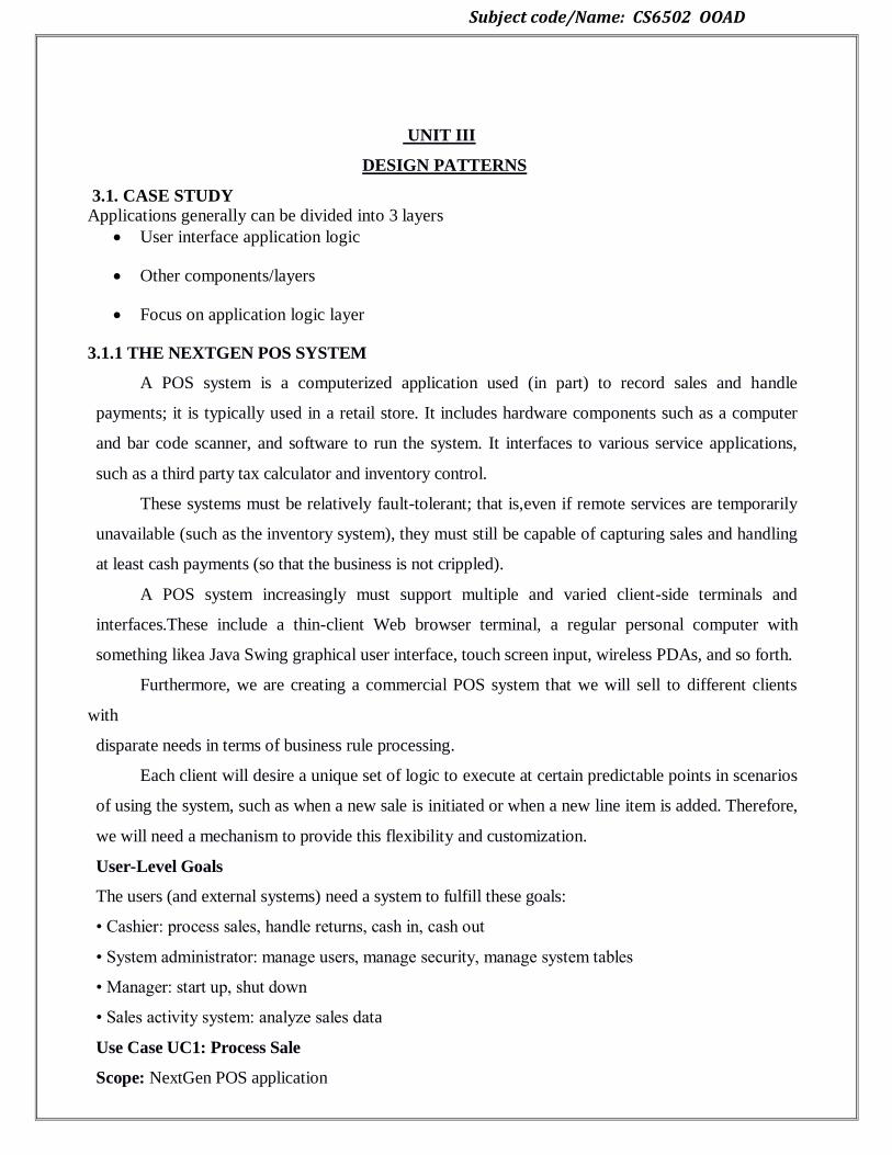
Subject code/Name: CS6502 OOAD
UNIT III
DESIGN PATTERNS
3.1. CASE STUDY
Applications generally can be divided into 3 layers
User interface application logic
Other components/layers
Focus on application logic layer
3.1.1 THE NEXTGEN POS SYSTEM
A POS system is a computerized application used (in part) to record sales and handle
payments; it is typically used in a retail store. It includes hardware components such as a computer
and bar code scanner, and software to run the system. It interfaces to various service applications,
such as a third party tax calculator and inventory control.
These systems must be relatively fault-tolerant; that is,even if remote services are temporarily
unavailable (such as the inventory system), they must still be capable of capturing sales and handling
at least cash payments (so that the business is not crippled).
A POS system increasingly must support multiple and varied client-side terminals and
interfaces.These include a thin-client Web browser terminal, a regular personal computer with
something likea Java Swing graphical user interface, touch screen input, wireless PDAs, and so forth.
Furthermore, we are creating a commercial POS system that we will sell to different clients
with
disparate needs in terms of business rule processing.
Each client will desire a unique set of logic to execute at certain predictable points in scenarios
of using the system, such as when a new sale is initiated or when a new line item is added. Therefore,
we will need a mechanism to provide this flexibility and customization.
User-Level Goals
The users (and external systems) need a system to fulfill these goals:
• Cashier: process sales, handle returns, cash in, cash out
• System administrator: manage users, manage security, manage system tables
• Manager: start up, shut down
• Sales activity system: analyze sales data
Use Case UC1: Process Sale
Scope: NextGen POS application

Subject code/Name: CS6502 OOAD
Level: user goal
Primary Actor: Cashier
Stakeholders and Interests:
Cashier: Wants accurate, fast entry, and no payment errors, as cash drawer shortages are deducted
from his/her salary.
Salesperson: Wants sales commissions updated.
Customer: Wants purchase and fast service with minimal effort. Wants easily visible display of
entered items and prices. Wants proof of purchase to support returns.
Company: Wants to accurately record transactions and satisfy customer interests. Wants to ensure
that
Payment Authorization Service payment receivables are recorded. Wants some fault tolerance to
allow sales capture even if server components (e.g., remote credit validation) are unavailable. Wants
automatic and fast update of accounting and inventory.
Manager: Wants to be able to quickly perform override operations, and easily debug Cashier
problems.
Government Tax Agencies: Want to collect tax from every sale. May be multiple agencies, such as
national,state, and county.
Payment Authorization Service: Wants to receive digital authorization requests in the correct format
and protocol. Wants to accurately account for their payables to the store.
Preconditions: Cashier is identified and authenticated.
Success Guarantee (Postconditions): Sale is saved. Tax is correctly calculated. Accounting and
Inventory are updated. Commissions recorded. Receipt is generated. Payment authorization approvals
are recorded.
Main Success Scenario (Basic Flow):
1. Customer arrives at POS checkout with goods and/or services to purchase.
2. Cashier starts a new sale.
3. Cashier enters item identifier.
4. System records sale line item and presents item description, price, and running total. Price
calculated from a set of price rules.
Cashier repeats steps 3-4 until indicates done.
5. System presents total with taxes calculated.
6. Cashier tells Customer the total, and asks for payment.
7. Customer pays and System handles payment.

Subject code/Name: CS6502 OOAD
8. System logs completed sale and sends sale and payment information to the external Accounting
system (for accounting and commissions) and Inventory system (to update inventory).
9. System presents receipt.
10. Customer leaves with receipt and goods (if any).
Extensions (Alternative Flows):
*a. At any time, Manager requests an override operation:
1. System enters Manager-authorized mode.
2. Manager or Cashier performs one Manager-mode operation. e.g., cash balance change,
resume a suspended sale on another register, void a sale, etc.
3. System reverts to Cashier-authorized mode.
*b. At any time, System fails:
To support recovery and correct accounting, ensure all transaction sensitive state and events can be
recovered from any step of the scenario.
1. Cashier restarts System, logs in, and requests recovery of prior state.
2. System reconstructs prior state.
2a. System detects anomalies preventing recovery:
1. System signals error to the Cashier, records the error, and enters a clean
state.
2. Cashier starts a new sale.
1a. Customer or Manager indicate to resume a suspended sale.
1. Cashier performs resume operation, and enters the ID to retrieve the sale.
2. System displays the state of the resumed sale, with subtotal.
2a. Sale not found.
1. System signals error to the Cashier.
2. Cashier probably starts new sale and re-enters all items.
3. Cashier continues with sale (probably entering more items or handling payment).
3.1.2 Inception:
Inception is the initial stage of project. It deals with approximate vision, business case,
scope of project and vague estimation.
Initial stage of project approximate vision Business case and scope Vague estimate
Inception is the smallest phase in the project, and ideally it should be quite short. If the
Inception Phase is long then it may be an indication of excessive up-front specification, which
is contrary to the spirit of the Unified Process.

Subject code/Name: CS6502 OOAD
The following are typical goals for the Inception
phase. Establish a justification or business case for the
project Establish the project scope and boundary
conditions
Outline the use cases and key requirements that will drive the design tradeoffs
Outline one or more candidate architectures
Identify risks
Prepare a preliminary project schedule and cost estimate
The Lifecycle Objective Milestone marks the end of the Inception
phase. Advantages of inception:
Estimation or plans are expected to be reliable.
After inception, design architecture can be made easily because all the use cases are
written in detail.
3.2. USE CASE MODELING
The Use Case Model describes the proposed functionality of the new system. A Use
Case represents a discrete unit of interaction between a user (human or machine) and the system.
A Use Case is a single unit of meaningful work; for example login to system, register with
system and create order are all Use Cases. Each Use Case has a description which describes the
functionality that will be built in the proposed system. A Use Case may 'include' another Use
Case's functionality or 'extend' another Use Case with its own behaviour. Use Cases are typically
related to 'actors'. An actor is a human or machine entity that interacts with the system to perform
meaningful work.
Actor, Kinds of Actors:
An Actor is a user of the system. This includes both human users and other computer
systems. An Actor uses a Use Case to perform some piece of work which is of value to the
business.
The set of Use Cases an actor has access to define their overall role in the system and the scope of
their action.
Constraints, Requirements and Scenarios.

Subject code/Name: CS6502 OOAD
The formal specification of a Use Case includes:
1. Requirements:
These are the formal functional requirements that a Use Case must provide to the end
user. They correspond to the functional specifications found in structured methodologies. A
requirement is a contract that the Use Case will perform some action or provide some value to the
system.
2. Constraints:
These are the formal rules and limitations that a Use Case operates under, and includes
pre- post- and invariant conditions. A pre-condition specifies what must have already occurred or
be in place before the Use Case may start. A post-condition documents what will be true once
the Use Case is complete. An invariant specifies what will be true throughout the time the
Use Case operates.
3.Scenarios:
Scenarios are formal descriptions of the flow of events that occurs during a Use Case
instance. These are usually described in text and correspond to a textual representation of the
Sequence Diagram.
3.2.1 Relating Use Case
Use case relationships is divided into three types
1. Include relationship
2. Extend relationship
3. Generalization
3.2.1.1. Include relationship:
It is common to have some practical behavior that is common across several use
cases. It is
simply to underline it or highlight it in some fashion
Example:
Paying by credit: Include Handle Credit Payment
Subject code/Name: CS6502 OOAD
3.2.1.2. Extend relationship:
Extending the use case or adding new use case to the process Extending use case is
triggered by some conditions called extension point.
3.2.1.3. Generalization:
Complicated work and unproductive time is spending in this use case relationship. Use
case experts are successfully doing use case work without this relationship.
Includes and Extends relationships between Use Cases
One Use Case may include the functionality of another as part of its normal processing.
Generally, it is assumed that the included Use Case will be called every time the basic path is
run. An example may be to list a set of customer orders to choose from before modifying a
selected order in this case the <list orders> Use Case may be ncluded every time the <modify
order> Use Case is run. A Use Case may be included by one or more Use Cases, so it helps
to reduce duplication of functionality by factoring out common behavior into Use Cases that are re-
used many times. One Use Case may extend the behavior of another - typically when
exceptional circumstances are encountered.
Relationships between Use Cases
Use cases could be organized using following
relationships: Generalization
Associatio
n Extend
Include
Generalization between Use Cases
Generalization between use cases is similar to generalization between classes;
child use case inherits properties and behaviour of the parent use case and may override the
behavior of the parent.
NOTATION
:
Generalization is rendered as a solid directed line with a large open arrowhead (same as
generalization between classes).
Generalization between use cases
Association between Use Cases
Use cases can only be involved in binary Associations. Two use cases specifying the same
subject cannot be associated since each of them individually describes a complete usage of the

Subject code/Name: CS6502 OOAD
system.
Extend Relationship:
Extend is a directed relationship from an extending use case to an extended use case
that specifies how and when the behaviour defined in usually supplementary (optional)
extending use case can be inserted into the behaviour defined in the use case to be extended.
The extension takes place at one or more extension points defined in the extended use case.
The extend relationship is owned by the extending use case. The same extending use
case
Can extend more than one use case, and extending use case may itself be
extended.
Extend relationship between use cases is shown by a dashed arrow with an open
arrowhead from the extending use case to the extended (base) use case.
The arrow is labelled with the keyword Registration use case is meaningful on its own, and
it could be extended with optional Get Help On Registration use case.
The condition of the extend relationship as well as the references to the extension points
are optionally shown in a Note attached to the corresponding extend relationship.
Registration use case is conditionally extended by Get Help On Registration use case in
extension point Registration Help
Include Relationship:
An include relationship is a directed relationship between two use cases, implying that
the behavior of the required (not optional) included use case is inserted into the behavior of
the including (base) use case. Including use case depends on the addition of the included use case.
The include relationship is intended to be used when there are common parts of the
behavior of two or more use cases. This common part is extracted into a separate use case to be
included by all the base use cases having this part in common.
As the primary use of the include relationship is to reuse common parts, including use
cases are usually not complete by themselves but dependent on the included use cases.
Include relationship between use cases is shown by a dashed arrow with an open
arrowhead from the including (base) use case to the included (common part) use case. The arrow
is labeled with the keyword «include».
Major elements of the business use case diagram are shown on the picture below. Note again,
both business use case as well as business actor are not defined in UML standard, so you will either
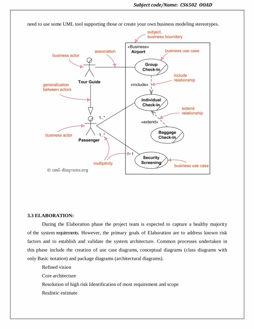
Subject code/Name: CS6502 OOAD
need to use some UML tool supporting those or create your own business modeling stereotypes.
3.3 ELABORATION:
During the Elaboration phase the project team is expected to capture a healthy majority
of the system requirements. However, the primary goals of Elaboration are to address known risk
factors and to establish and validate the system architecture. Common processes undertaken in
this phase include the creation of use case diagrams, conceptual diagrams (class diagrams with
only Basic notation) and package diagrams (architectural diagrams).
Refined vision
Core architecture
Resolution of high risk Identification of most requirement and scope
Realistic estimate

Subject code/Name: CS6502 OOAD
3.3.1 DOMAIN MODELS:
What is a domain model?
Motivation: why create a domain model?
Guideline: how to create a domain model?
What is a domain model?
A domain model is a visual representation of conceptual classes or real-situation objects in a
domain. Domain models have also been called conceptual models, domain object models and
analysis object models.
In the UP ―Domain Model‖ means a representation of real-situation conceptual classes, not of
software objects. The term does not mean a set of diagrams describing software classes, the
domain layer of a software architecture or software objects with responsibilities. Applying
UML notation, a domain model is illustrated with a set of class diagrams in which no
operations (method signature) are defined. It provides a conceptual perspective. It may show:
Domain objects or conceptual classes
Associations between conceptual classes
Attributes of conceptual classes
Definition: why call a domain model a “visual dictionary”?
The information it illustrates (using UML notation) could alternatively have been expressed in
plain text (in the UP glossary). But it‘s easy to understand the terms and especially their
relationships in a visual language, since our brains are good at understanding visual elements
and line connection.
The domain model is a visual dictionary of the noteworthy abstractions, domain vocabulary,
and information content of the domain.
Definition: is a domain model picture of software business objects?
The following elements are not suitable in a domain model:
Software artifacts, such as a window or a database, unless the domain being modeled are of
software concepts, such as a model of graphical user interfaces.
Responsibilities or methods.
Definition: what are 2-traditional meanings of “domain model”?
Domain model is conceptual perspective of objects in a real situation of the world, not a
software perspective. But the term is overloaded; it also has been used to mean ―the domain
layer of software objects‖.
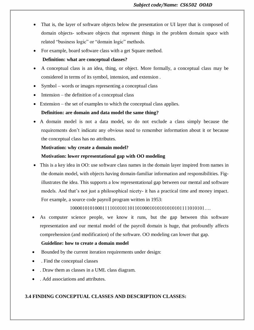
Subject code/Name: CS6502 OOAD
That is, the layer of software objects below the presentation or UI layer that is composed of
domain objects- software objects that represent things in the problem domain space with
related ―business logic‖ or ―domain logic‖ methods.
For example, board software class with a get Square method.
Definition: what are conceptual classes?
A conceptual class is an idea, thing, or object. More formally, a conceptual class may be
considered in terms of its symbol, intension, and extension .
Symbol – words or images representing a conceptual class
Intension – the definition of a conceptual class
Extension – the set of examples to which the conceptual class applies.
Definition: are domain and data model the same thing?
A domain model is not a data model, so do not exclude a class simply because the
requirements don‘t indicate any obvious need to remember information about it or because
the conceptual class has no attributes.
Motivation: why create a domain model?
Motivation: lower representational gap with OO modeling
This is a key idea in OO: use software class names in the domain layer inspired from names in
the domain model, with objects having domain-familiar information and responsibilities. Fig-
illustrates the idea. This supports a low representational gap between our mental and software
models. And that‘s not just a philosophical nicety- it has a practical time and money impact.
For example, a source code payroll program written in 1953:
100001010100011110101011011010001010101010101111010101….
As computer science people, we know it runs, but the gap between this software
representation and our mental model of the payroll domain is huge, that profoundly affects
comprehension (and modification) of the software. OO modeling can lower that gap.
Guideline: how to create a domain model
Bounded by the current iteration requirements under design:
. Find the conceptual classes
. Draw them as classes in a UML class diagram.
. Add associations and attributes.
3.4 FINDING CONCEPTUAL CLASSES AND DESCRIPTION CLASSES:

Subject code/Name: CS6502 OOAD
Finding conceptual classes
Guideline: how to find conceptual classes?
3-strategies to find conceptual classes
. Reuse or modify existing models. This is the first, best, and usually easiest approach.
. Use a category list
Identify noun phrases.
Reusing existing models is excellent, but outside our scope. The second method, using a
category list, is also useful.
Guideline: when to model with description classes?
A description class contains information that describes something else. For example, a
Product Description that records the price, picture, and text description of an Item. This was
first named the Item- Descriptor pattern.
Motivation: why use description classes?
Guideline: when are description classes useful?
3.5 ASSOCIATION:
The UML Class diagram is used to visually describe the problem domain in terms of
types of object (classes) related to each other in different ways. There are three primary inter-
object relationships: association, aggregation, and composition. Using the right relationship
line is important for placing implicit restrictions on the visibility and propagation of changes to
the related classes, matter which play major role in reducing system complexity.
Association
The most abstract way to describe static relationship between classes is using the
‗Association‘ link, which simply states that there is some kind of a link or a dependency between
two classes or more.

Subject code/Name: CS6502 OOAD
Weak Association
ClassA may be linked to ClassB in order to show that one of its methods includes parameter of
ClassB instance, or returns instance of ClassB.
3.6 ATTRIBUTES:
It is useful to identify those attributes of conceptual classes that are needed to satisfy the
information requirements of the current scenarios under development.
An attribute is a logical data value of an object.
Guideline: when to show attributes?
3.6.1 Representation of Attributes
More Notations
Guideline: where to record attribute requirements?
Derived attributes
Guideline: what are suitable attribute types?
Focus on data type attributes in the domain model
Data types
Perspectives: what about attribute in code?
Guideline: when to define new data type classes?
Applying UML: where to illustrating these data type classes?
Guideline: no attributes representing foreign keys
Guideline: modeling quantities and units
3.6.2 Notation:

Subject code/Name: CS6502 OOAD
3.7 DOMAIN MODEL REFINEMENT:
New concepts for the NextGen domain model
Noun phrase identification from the use cases
Authorization service transactions
Generalization
Defining conceptual super classes and sub classes
Generalization and conceptual class definition
Generalization and class sets
Conceptual subclass definition conformance
Conceptual sub class set conformance
What is a correct conceptual sub class?
When to define a conceptual subclass?
Motivations to partition a conceptual class into sub classes
When to define conceptual super class?
3.8 FINDING CONCEPTUAL CLASS HIERARCHIES:
CONCEPTUAL CLASSES
Informally, a conceptual class is an idea, thing, or object. More formally, a conceptual class
may be considered in terms of its symbol, intension, and extension.
Symbol - words or images representing a conceptual class.
Intension - the definition of a conceptual class.
Extension - the set of examples to which the conceptual class applies.

Subject code/Name: CS6502 OOAD
For example, consider the conceptual class for the event of a purchase transaction. We may
choose to name it by the symbol Sale. The intension of a Sale may state that it "represents the
event of a purchase transaction, and has a date and time." The extension of Sale is all the
examples of sales; in other words, the set of all sales
Payment classes
Authorization service classes
Authorization transaction classes
3.9 AGGREGATION AND COMPOSITION
In cases where there‘s a part-of relationship between ClassA (whole) and ClassB (part),
we can be more specific and use the aggregation link instead of the association link, taking
special notice that ClassB can also be aggregated by other classes in the application (therefore
aggregation is also known as shared association).
So basically, the aggregation link doesn‘t state in any way that ClassA owns ClassB nor that there
is a parent-child relationship (when parent deleted all its child‘s are being deleted as a result)
between the two. Actually, quite the opposite! The aggregation link usually used to stress the
point that ClassA is not the exclusive container of ClassB, as in fact ClassB has another container.
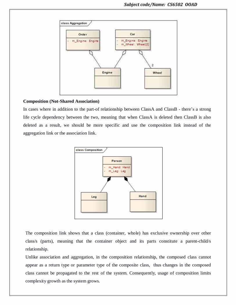
Subject code/Name: CS6502 OOAD
Composition (Not-Shared Association)
In cases where in addition to the part-of relationship between ClassA and ClassB - there‘s a strong
life cycle dependency between the two, meaning that when ClassA is deleted then ClassB is also
deleted as a result, we should be more specific and use the composition link instead of the
aggregation link or the association link.
The composition link shows that a class (container, whole) has exclusive ownership over other
class/s (parts), meaning that the container object and its parts constitute a parent-child/s
relationship.
Unlike association and aggregation, in the composition relationship, the composed class cannot
appear as a return type or parameter type of the composite class, thus changes in the composed
class cannot be propagated to the rest of the system. Consequently, usage of composition limits
complexity growth as the system grows.
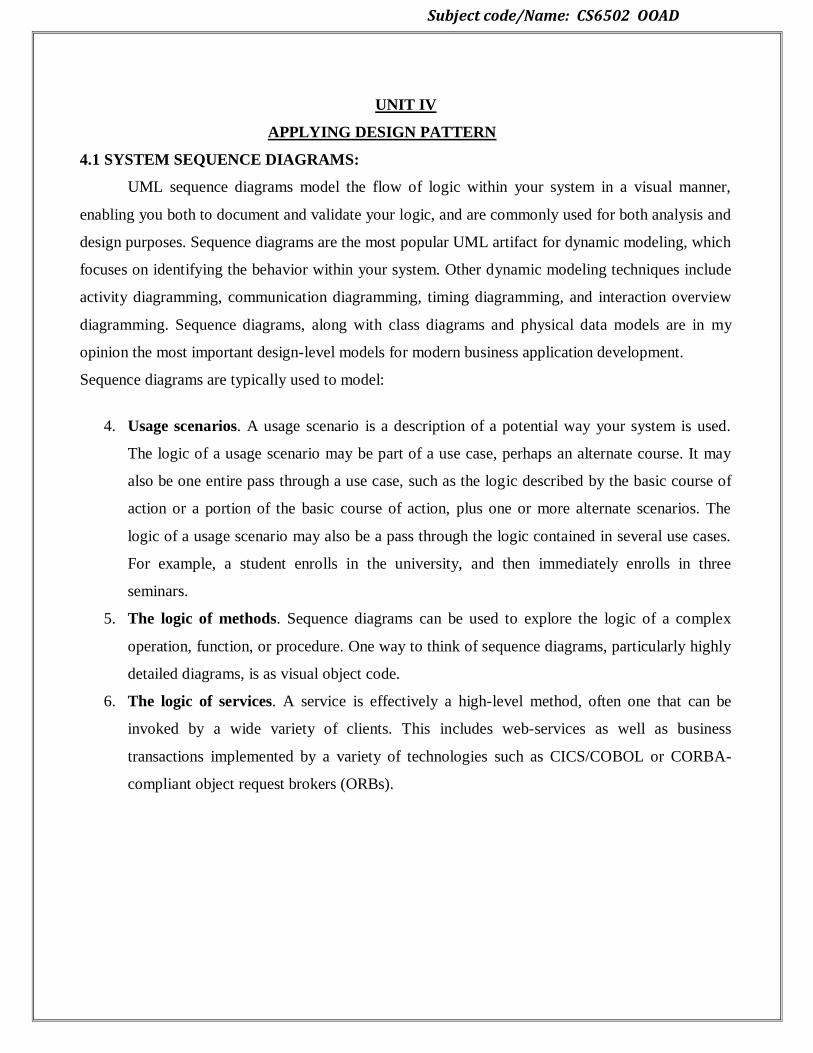
Subject code/Name: CS6502 OOAD
UNIT IV
APPLYING DESIGN PATTERN
4.1 SYSTEM SEQUENCE DIAGRAMS:
UML sequence diagrams model the flow of logic within your system in a visual manner,
enabling you both to document and validate your logic, and are commonly used for both analysis and
design purposes. Sequence diagrams are the most popular UML artifact for dynamic modeling, which
focuses on identifying the behavior within your system. Other dynamic modeling techniques include
activity diagramming, communication diagramming, timing diagramming, and interaction overview
diagramming. Sequence diagrams, along with class diagrams and physical data models are in my
opinion the most important design-level models for modern business application development.
Sequence diagrams are typically used to model:
4. Usage scenarios. A usage scenario is a description of a potential way your system is used.
The logic of a usage scenario may be part of a use case, perhaps an alternate course. It may
also be one entire pass through a use case, such as the logic described by the basic course of
action or a portion of the basic course of action, plus one or more alternate scenarios. The
logic of a usage scenario may also be a pass through the logic contained in several use cases.
For example, a student enrolls in the university, and then immediately enrolls in three
seminars.
5. The logic of methods. Sequence diagrams can be used to explore the logic of a complex
operation, function, or procedure. One way to think of sequence diagrams, particularly highly
detailed diagrams, is as visual object code.
6. The logic of services. A service is effectively a high-level method, often one that can be
invoked by a wide variety of clients. This includes web-services as well as business
transactions implemented by a variety of technologies such as CICS/COBOL or CORBA-
compliant object request brokers (ORBs).
Subject code/Name: CS6502 OOAD
4.1.1 Relationship between Sequence Diagrams and Use Case Diagrams:
One of the key tools of the united modelling language for behaviour modelling is the use-case
model. The behaviour of a use case can be described by means of interaction diagrams (sequence and
collaboration diagrams), activity charts and state diagrams or by pre-conditions and post- conditions,
as well as natural language text, where appropriate. This article explains a technique to describe use
cases by means of sequence diagrams. It compares sequence diagrams in order
to define sequence-diagram relationships for identifying and defining use-case relationships.
The unified modelling language (UML) provides system architects working on analysis and
design with one consistent language for specifying, visualizing, constructing and documenting the
artefacts of software systems, as well as for business modelling.
Use cases are a way of specifying required usages of a system. Typically, they are used to
capture the requirements of a system, that is, what a system is supposed to do. The key concepts
associated with the use-case model are actors and use cases. The users and any other systems that
may interact with the system are rep- resented as actors. Actors always model entities that are outside
the system. The required behaviour of the system is specified by one or more use cases, which are
defined according to the actors‘ needs. Each use case specifies some behaviour, possibly including
variants, which the system can perform in collaboration with one or more actors.
Sequence-diagram relationships are defined according to the most accepted semantics for use-
case relationships. In fact, we believe that our proposal could be useful for a better understanding of
the cited semantics. We believe that one of the contributions of our work is to provide semantics of
use-case relationships by means of sequence diagrams.
Describing Use Cases By Means Of Sequence Diagrams
Subject code/Name: CS6502 OOAD
This section explains a technique to describe use cases by means of sequence diagrams. In
fact, we will compare sequence diagrams in order to define sequence-diagram relationships, which
will be used for identifying and defining use-case relationships. Regarding the model-driven
development, we also show a discussion on how the development process and, in general, the
developer decisions affect both use-case modelling and sequence-diagram modelling, in particular,
the identification of use-case relationships. Our technique can be summarized as follows.
(i)A use-case model is built and the actors are connected to use cases. Each use case
represents a task in which the actor participates.
(ii) For each use case, a sequence diagram is built. Each sequence diagram specifies the main
interaction steps to be achieved for each task (i.e. use case).
Some of the interaction steps in a sequence diagram can be deployed in another sequence
diagram (or sub diagram).
(iii) From the sequence diagrams, use-case relationships are identified. Sequence sub
diagrams are identified with new use cases. Then, the inclusion relationships are identified between
the use cases specified and the new use cases.
(iv)The sequence diagrams are refined: some interaction steps are added as extensions to the
original sequence diagrams. These extensions are represented as new sequence (sub) diagrams. These
new sub diagrams are identified with new use cases. Sometimes, new abstract use cases can be
defined representing generic sequence diagrams, and particular cases of abstract use cases are
identified in which interaction steps are added or rewritten.
(v) From the refined sequence diagrams, new use-case relationships are discovered: new
generalization/ specialization and extension relationships. Generalization/specialization relationships
between abstract and particular use cases are identified. Extension relationships are identified
between old use cases and their extending use cases.
(vi)Some of the previous steps might be applied incrementally in the development process.
4.2 LOGICAL ARCHITECTURE AND UML PACKAGE DIAGRAM:
LOGICAL ARCHITECTURE:
The Large-Scale
•At this level, the design of a typical OO system is based on several architectural layers, such as
–UI layer,
–Application logic (or "domain") layer,
–Technical Services
Subject code/Name: CS6502 OOAD
Layers
•Layers a coarse-grained grouping of classes, packages, or subsystems that has cohesive (strongly
related) responsibilities for a major aspect of the system.
–E.g. Application Logic and Domain Objects—software objects representing domain
concepts (for example, a software class Sale) that fulfill application requirements, such as
calculating a sale total.
•Application layer is the focus of Use Cases.
•Higher layers (such as UI layer) call upon services of lower layers, but not normally vice versa.
•In a strict layered architecture, a layer only calls upon the services of the layer directly below it.
–Common in network protocols
•But not in information systems, which have a relaxed layered architecture, in which a higher layer
calls upon several lower layers.
–For example, UI layer may call upon its directly subordinate application logic layer, and also
upon elements of a lower technical service layer, for logging and so forth.
Software Architecture
•A software architecture is
–the set of significant decisions about the organization of a software system,
–the selection of the structural elements and their interfaces by which the system is
composed,
–together with their behaviour as specified in the collaborations among those elements, and
–the composition of these structural and behavioural elements into progressively larger
subsystems
PACKAGE DIAGRAMS:
Package diagram is UML structure diagram which shows packages and dependencies between the
packages.
Model diagrams allow to show different views of a system, for example, as multi-layered (aka multi-
tiered) application - multi-layered application model.
4.2.1 Notations:
The following nodes and edges are typically drawn in a package diagram: package, packageable
element, dependency, element import, package import, package merge.

Subject code/Name: CS6502 OOAD
Package is a namespace used to group together elements that are semantically related and might
change together. It is a general purpose mechanism to organize elements into groups to provide better
structure for system model.
Owned members of a package should all be packageable elements. If a package is removed from a
model, so are all the elements owned by the package. Package by itself is packageable element, so
any package could be also a member of other packages.
Because package is a namespace, elements of related or the same type should have unique names
within the enclosing package. Different types of elements are allowed to have the same name.
As a namespace, a package can import either individual members of other packages or all the
members of other packages. Package can also be merged with other packages.
A package is rendered as a tabbed folder - a rectangle with a small tab attached to the left side of the
top of the rectangle. If the members of the package are not shown inside the package rectangle, then
the name of the package should be placed inside.
Package org.hibernate
The members of the package may be shown within the boundaries of the package. In this case the
name of the package should be placed on the tab.
Package org.hibernate contains Session Factory and Session
A diagram showing a package with content is allowed to show only a subset of the contained
elements according to some criterion.
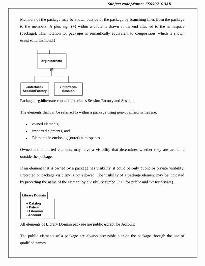
Subject code/Name: CS6502 OOAD
Members of the package may be shown outside of the package by branching lines from the package
to the members. A plus sign (+) within a circle is drawn at the end attached to the namespace
(package). This notation for packages is semantically equivalent to composition (which is shown
using solid diamond.)
Package org.hibernate contains interfaces Session Factory and Session.
The elements that can be referred to within a package using non-qualified names are:
owned elements,
imported elements, and
Elements in enclosing (outer) namespaces.
Owned and imported elements may have a visibility that determines whether they are available
outside the package.
If an element that is owned by a package has visibility, it could be only public or private visibility.
Protected or package visibility is not allowed. The visibility of a package element may be indicated
by preceding the name of the element by a visibility symbol ("+" for public and "-" for private).
All elements of Library Domain package are public except for Account
The public elements of a package are always accessible outside the package through the use of
qualified names.
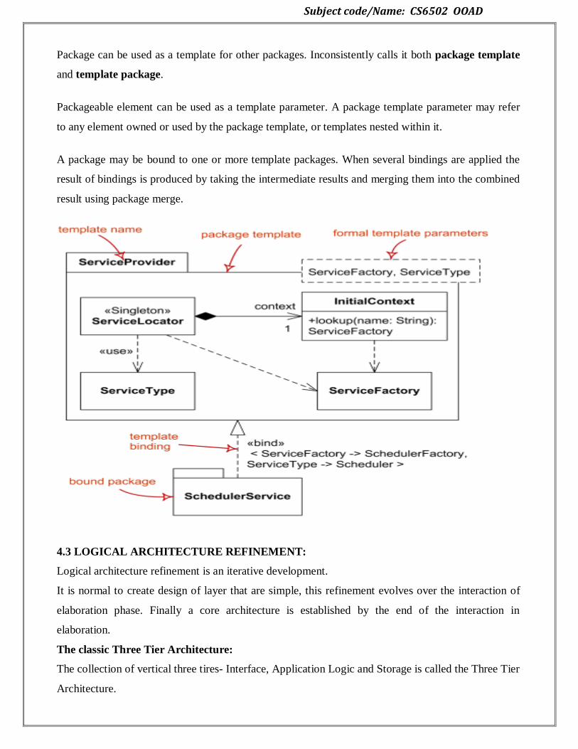
Subject code/Name: CS6502 OOAD
Package can be used as a template for other packages. Inconsistently calls it both package template
and template package.
Packageable element can be used as a template parameter. A package template parameter may refer
to any element owned or used by the package template, or templates nested within it.
A package may be bound to one or more template packages. When several bindings are applied the
result of bindings is produced by taking the intermediate results and merging them into the combined
result using package merge.
4.3 LOGICAL ARCHITECTURE REFINEMENT:
Logical architecture refinement is an iterative development.
It is normal to create design of layer that are simple, this refinement evolves over the interaction of
elaboration phase. Finally a core architecture is established by the end of the interaction in
elaboration.
The classic Three Tier Architecture:
The collection of vertical three tires- Interface, Application Logic and Storage is called the Three Tier
Architecture.
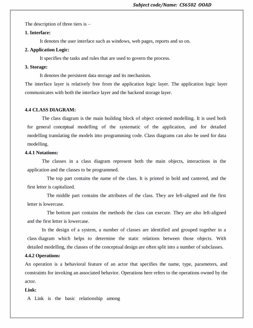
Subject code/Name: CS6502 OOAD
The description of three tiers is –
1. Interface:
It denotes the user interface such as windows, web pages, reports and so on.
2. Application Logic:
It specifies the tasks and rules that are used to govern the process.
3. Storage:
It denotes the persistent data storage and its mechanism.
The interface layer is relatively free from the application logic layer. The application logic layer
communicates with both the interface layer and the backend storage layer.
4.4 CLASS DIAGRAM:
The class diagram is the main building block of object oriented modelling. It is used both
for general conceptual modelling of the systematic of the application, and for detailed
modelling translating the models into programming code. Class diagrams can also be used for data
modelling.
4.4.1 Notations:
The classes in a class diagram represent both the main objects, interactions in the
application and the classes to be programmed.
The top part contains the name of the class. It is printed in bold and cantered, and the
first letter is capitalized.
The middle part contains the attributes of the class. They are left-aligned and the first
letter is lowercase.
The bottom part contains the methods the class can execute. They are also left-aligned
and the first letter is lowercase.
In the design of a system, a number of classes are identified and grouped together in a
class diagram which helps to determine the static relations between those objects. With
detailed modelling, the classes of the conceptual design are often split into a number of subclasses.
4.4.2 Operations:
An operation is a behavioral feature of an actor that specifies the name, type, parameters, and
constraints for invoking an associated behavior. Operations here refers to the operations owned by the
actor.
Link:
A Link is the basic relationship among

Subject code/Name: CS6502 OOAD
objects.
4.4.3 Attributes:
Refers to all of the Properties that are direct (i.e. not inherited or imported) attributes of the actor.
4.4.4 Generalization:
A use-case-generalization is a relationship from a child use case to a parent use case, specifying
how a child can specialize all behaviour and characteristics described for the parent.
Example:
A parent use case may be specialized into one or more child use cases that represent more
specific forms of the parent. Neither parent nor child is necessarily abstract, although the parent in
most cases is abstract. A child inherits all structure, behaviour, and relationships of the parent.
Children of the same parent are all specializations of the parent. This is generalization as applicable
to use cases (see also Guidelines: Generalization).
Generalization is used when you find two or more use cases that have commonalities in
behaviour, structure, and purpose. When this happens, you can describe the shared parts in a new,
often abstract, use case, which is then specialized by child use cases.
Example:

Subject code/Name: CS6502 OOAD
4.4.5 Association class:
The UML Class diagram is used to visually describe the problem domain in terms of
types of object (classes) related to each other in different ways. There are three primary inter-
object relationships: association, aggregation, and composition. Using the right relationship
line is important for placing implicit restrictions on the visibility and propagation of changes to
the related classes, matter which play major role in reducing system complexity.
Association
The most abstract way to describe static relationship between classes is using the
‗Association‘ link, which simply states that there is some kind of a link or a dependency between
two classes or more.
Weak Association
ClassA may be linked to ClassB in order to show that one of its methods includes parameter of
ClassB instance, or returns instance of ClassB.
Aggregation (Shared Association) and Composition (Not-Shared Association)
In cases where there‘s a part-of relationship between ClassA (whole) and ClassB (part),
we can be more specific and use the aggregation link instead of the association link, taking
special notice that ClassB can also be aggregated by other classes in the application (therefore
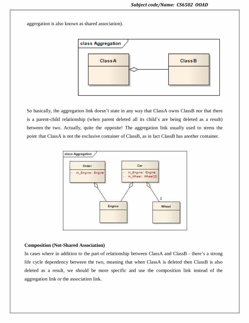
Subject code/Name: CS6502 OOAD
aggregation is also known as shared association).
So basically, the aggregation link doesn‘t state in any way that ClassA owns ClassB nor that there
is a parent-child relationship (when parent deleted all its child‘s are being deleted as a result)
between the two. Actually, quite the opposite! The aggregation link usually used to stress the
point that ClassA is not the exclusive container of ClassB, as in fact ClassB has another container.
Composition (Not-Shared Association)
In cases where in addition to the part-of relationship between ClassA and ClassB - there‘s a strong
life cycle dependency between the two, meaning that when ClassA is deleted then ClassB is also
deleted as a result, we should be more specific and use the composition link instead of the
aggregation link or the association link.
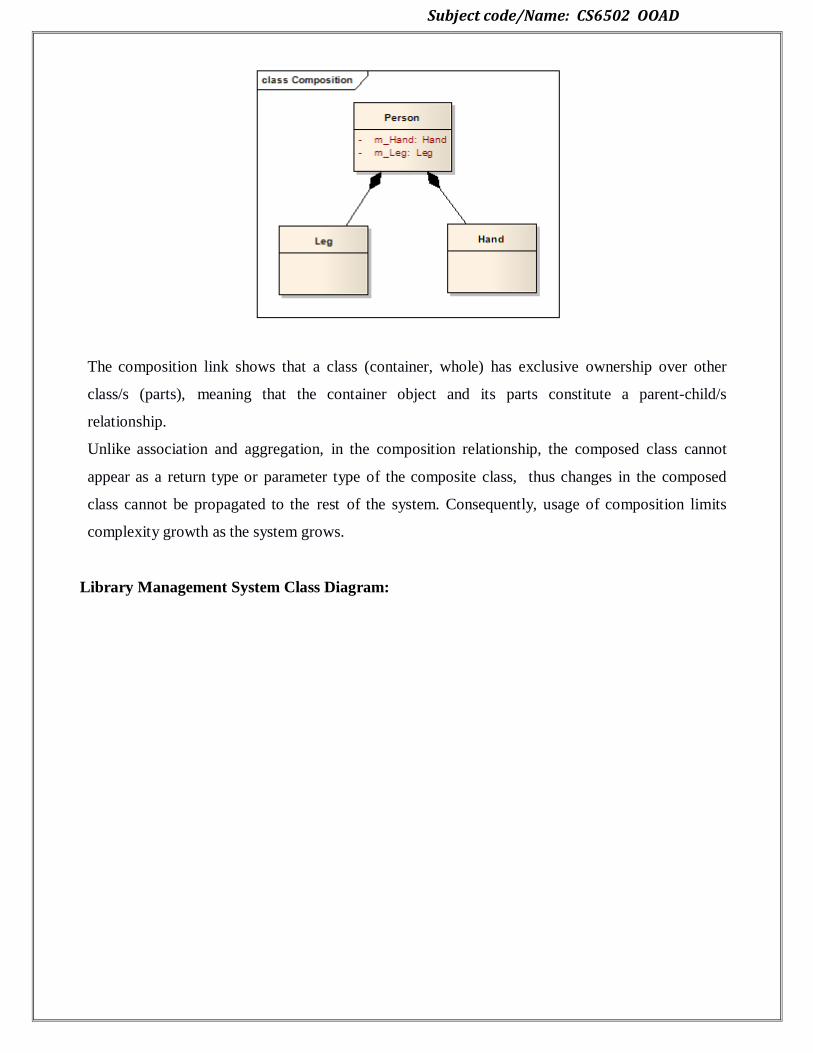
Subject code/Name: CS6502 OOAD
The composition link shows that a class (container, whole) has exclusive ownership over other
class/s (parts), meaning that the container object and its parts constitute a parent-child/s
relationship.
Unlike association and aggregation, in the composition relationship, the composed class cannot
appear as a return type or parameter type of the composite class, thus changes in the composed
class cannot be propagated to the rest of the system. Consequently, usage of composition limits
complexity growth as the system grows.
Library Management System Class Diagram:
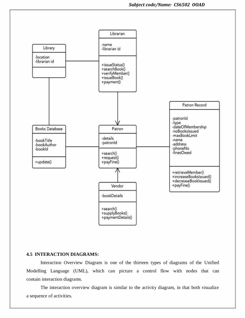
Subject code/Name: CS6502 OOAD
4.5 INTERACTION DIAGRAMS:
Interaction Overview Diagram is one of the thirteen types of diagrams of the Unified
Modelling Language (UML), which can picture a control flow with nodes that can
contain interaction diagrams.
The interaction overview diagram is similar to the activity diagram, in that both visualize
a sequence of activities.
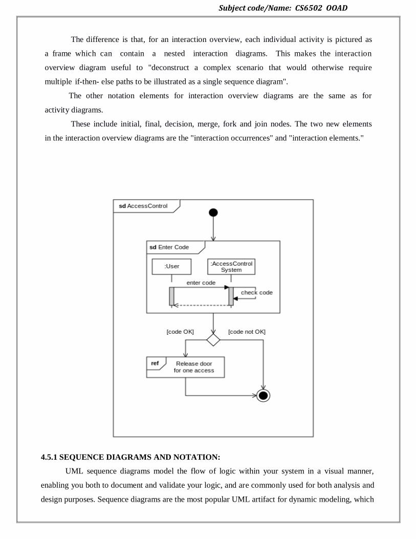
Subject code/Name: CS6502 OOAD
The difference is that, for an interaction overview, each individual activity is pictured as
a frame which can contain a nested interaction diagrams. This makes the interaction
overview diagram useful to "deconstruct a complex scenario that would otherwise require
multiple if-then- else paths to be illustrated as a single sequence diagram".
The other notation elements for interaction overview diagrams are the same as for
activity diagrams.
These include initial, final, decision, merge, fork and join nodes. The two new elements
in the interaction overview diagrams are the "interaction occurrences" and "interaction elements."
4.5.1 SEQUENCE DIAGRAMS AND NOTATION:
UML sequence diagrams model the flow of logic within your system in a visual manner,
enabling you both to document and validate your logic, and are commonly used for both analysis and
design purposes. Sequence diagrams are the most popular UML artifact for dynamic modeling, which
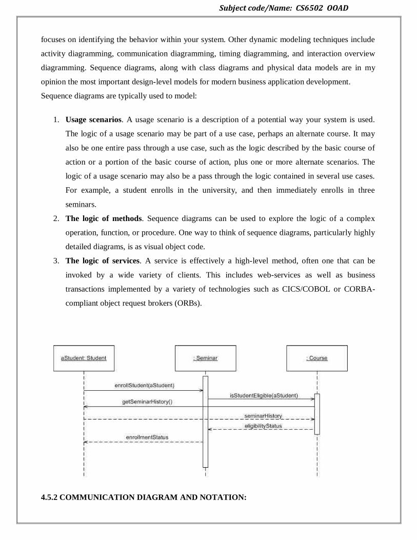
Subject code/Name: CS6502 OOAD
focuses on identifying the behavior within your system. Other dynamic modeling techniques include
activity diagramming, communication diagramming, timing diagramming, and interaction overview
diagramming. Sequence diagrams, along with class diagrams and physical data models are in my
opinion the most important design-level models for modern business application development.
Sequence diagrams are typically used to model:
1. Usage scenarios. A usage scenario is a description of a potential way your system is used.
The logic of a usage scenario may be part of a use case, perhaps an alternate course. It may
also be one entire pass through a use case, such as the logic described by the basic course of
action or a portion of the basic course of action, plus one or more alternate scenarios. The
logic of a usage scenario may also be a pass through the logic contained in several use cases.
For example, a student enrolls in the university, and then immediately enrolls in three
seminars.
2. The logic of methods. Sequence diagrams can be used to explore the logic of a complex
operation, function, or procedure. One way to think of sequence diagrams, particularly highly
detailed diagrams, is as visual object code.
3. The logic of services. A service is effectively a high-level method, often one that can be
invoked by a wide variety of clients. This includes web-services as well as business
transactions implemented by a variety of technologies such as CICS/COBOL or CORBA-
compliant object request brokers (ORBs).
4.5.2 COMMUNICATION DIAGRAM AND NOTATION:
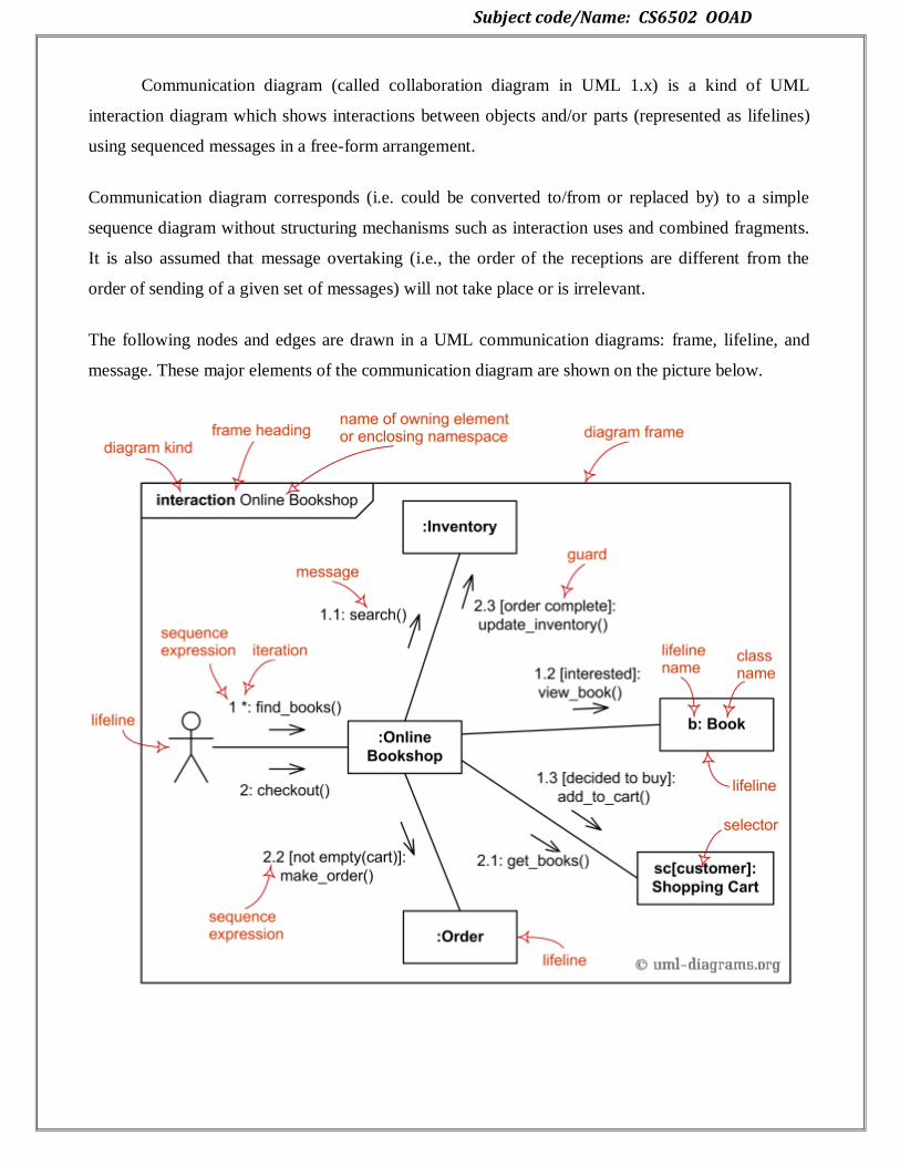
Subject code/Name: CS6502 OOAD
Communication diagram (called collaboration diagram in UML 1.x) is a kind of UML
interaction diagram which shows interactions between objects and/or parts (represented as lifelines)
using sequenced messages in a free-form arrangement.
Communication diagram corresponds (i.e. could be converted to/from or replaced by) to a simple
sequence diagram without structuring mechanisms such as interaction uses and combined fragments.
It is also assumed that message overtaking (i.e., the order of the receptions are different from the
order of sending of a given set of messages) will not take place or is irrelevant.
The following nodes and edges are drawn in a UML communication diagrams: frame, lifeline, and
message. These major elements of the communication diagram are shown on the picture below.
Subject code/Name: CS6502 OOAD
4.6 APPLYING GOF DESIGN PATTERN:
The Gang of Four are the four authors of the book, "Design Patterns: Elements of Reusable
Object-Oriented Software". In this article their twenty-three design patterns are described with links
to UML diagrams, source code and real-world examples for each.
4.6.1 ADAPTER DESIGN PATTERN
The adapter pattern is a design pattern that is used to allow two incompatible types to
communicate. Where one class relies upon a specific interface that is not implemented by another
class, the adapter acts as a translator between the two types.
What is the Adapter Pattern?
The adapter pattern is a Gang of Four design pattern. This is a structural pattern as it defines a
manner for creating relationships between classes. The adapter design pattern is used to provide a link
between two otherwise incompatible types by wrapping the "adaptee" with a class that supports the
interface required by the client.
Let's take an example where we have a personnel system and an intranet solution that
displays, amongst other things, a telephone list. It may be that the personnel system includes methods
that permit the retrieval of employees, including their name, job title and telephone number. The
intranet solution may include a plug-in system that can be used to source this data but the plug-in
must provide a specific interface that is not supported by the personnel software.
In this case, we can create a new class to be an adapter. This class will provide the intranet's
desired interface and will hold an object of the type required by the personnel system. When the
intranet makes a request, this request can be passed to the correct method of the personnel system.
The response from the personnel system will then be translated to a format that can be used by the
intranet.
Implementing the Adapter Pattern
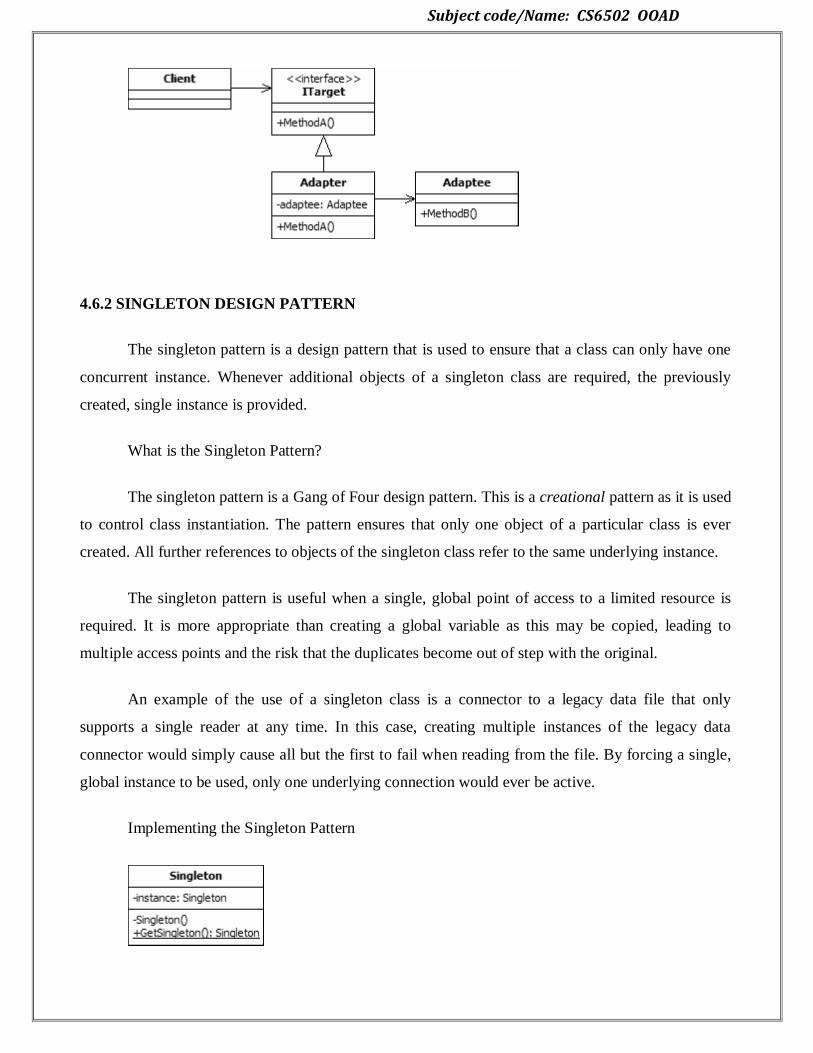
Subject code/Name: CS6502 OOAD
4.6.2 SINGLETON DESIGN PATTERN
The singleton pattern is a design pattern that is used to ensure that a class can only have one
concurrent instance. Whenever additional objects of a singleton class are required, the previously
created, single instance is provided.
What is the Singleton Pattern?
The singleton pattern is a Gang of Four design pattern. This is a creational pattern as it is used
to control class instantiation. The pattern ensures that only one object of a particular class is ever
created. All further references to objects of the singleton class refer to the same underlying instance.
The singleton pattern is useful when a single, global point of access to a limited resource is
required. It is more appropriate than creating a global variable as this may be copied, leading to
multiple access points and the risk that the duplicates become out of step with the original.
An example of the use of a singleton class is a connector to a legacy data file that only
supports a single reader at any time. In this case, creating multiple instances of the legacy data
connector would simply cause all but the first to fail when reading from the file. By forcing a single,
global instance to be used, only one underlying connection would ever be active.
Implementing the Singleton Pattern

Subject code/Name: CS6502 OOAD
The UML class diagram above describes an implementation of the adapter design pattern. The
items in the diagram are described below:
Client. The client class is that which requires the use of an incompatible type. It expects to
interact with a type that implements the ITarget interface. However, the class that we wish it to use is
the incompatible Adaptee.
The UML class diagram above describes an implementation of the singleton pattern. In this
diagram the only public interface element is the static "GetSingleton" method. This method returns
the single instance held in the private "instance" variable. Usually an instance of the class is created
only when first requested. This lazy initialisation ensures that if the class is never required, resources
are not wasted.
The constructor for the class is marked as private. This prevents any external classes from
creating new instances. The class is also sealed to prevent inheritance, which could lead to
subclassing that breaks the singleton rules.
The following code shows the basic code of the design pattern implemented using C#:
One important item to note in the above code is the "_lockThis" object and the use of locking
within the "GetSingleton" method. As C# programs can be multithreaded, it is possible that two
threads could request the singleton before the instance variable is initialised. In rare cases, these two
threads may both create their own copies of the class, defeating the principle of the design pattern. By
locking the dummy "_lockThis" variable whilst checking, and possibly creating, the instance
variable, all other threads will be blocked for very brief period. This means that no two threads will
ever be able to simultaneously create their own copies of the object.
Example Singleton
The singleton pattern is often used to hold the state of a program, particular in rich client
applications. In the following example, a class is defined to hold the application's state. Two
properties are required, one for the user's login details and one for the maximum size of some element
that they can manipulate. To ensure that the state is only held in a single instance, the class uses the
singleton pattern approach.
NB: For brevity the two properties are defined using the .NET 3.0 automatically implemented
property syntax. For earlier versions of the .NET framework, these must be expanded.
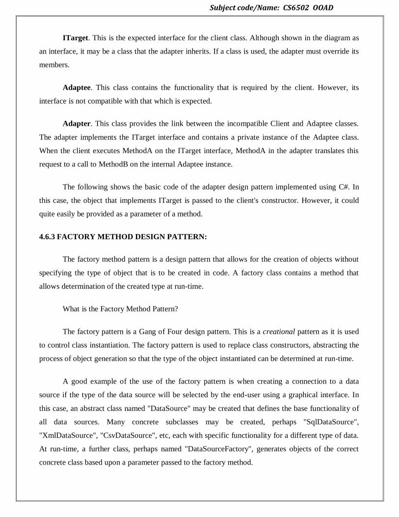
Subject code/Name: CS6502 OOAD
ITarget. This is the expected interface for the client class. Although shown in the diagram as
an interface, it may be a class that the adapter inherits. If a class is used, the adapter must override its
members.
Adaptee. This class contains the functionality that is required by the client. However, its
interface is not compatible with that which is expected.
Adapter. This class provides the link between the incompatible Client and Adaptee classes.
The adapter implements the ITarget interface and contains a private instance of the Adaptee class.
When the client executes MethodA on the ITarget interface, MethodA in the adapter translates this
request to a call to MethodB on the internal Adaptee instance.
The following shows the basic code of the adapter design pattern implemented using C#. In
this case, the object that implements ITarget is passed to the client's constructor. However, it could
quite easily be provided as a parameter of a method.
4.6.3 FACTORY METHOD DESIGN PATTERN:
The factory method pattern is a design pattern that allows for the creation of objects without
specifying the type of object that is to be created in code. A factory class contains a method that
allows determination of the created type at run-time.
What is the Factory Method Pattern?
The factory pattern is a Gang of Four design pattern. This is a creational pattern as it is used
to control class instantiation. The factory pattern is used to replace class constructors, abstracting the
process of object generation so that the type of the object instantiated can be determined at run-time.
A good example of the use of the factory pattern is when creating a connection to a data
source if the type of the data source will be selected by the end-user using a graphical interface. In
this case, an abstract class named "DataSource" may be created that defines the base functionality of
all data sources. Many concrete subclasses may be created, perhaps "SqlDataSource",
"XmlDataSource", "CsvDataSource", etc, each with specific functionality for a different type of data.
At run-time, a further class, perhaps named "DataSourceFactory", generates objects of the correct
concrete class based upon a parameter passed to the factory method.
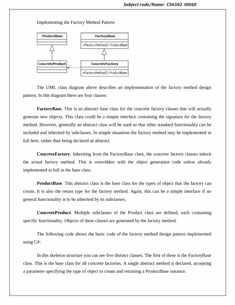
Subject code/Name: CS6502 OOAD
Implementing the Factory Method Pattern
The UML class diagram above describes an implementation of the factory method design
pattern. In this diagram there are four classes:
FactoryBase. This is an abstract base class for the concrete factory classes that will actually
generate new objects. This class could be a simple interface containing the signature for the factory
method. However, generally an abstract class will be used so that other standard functionality can be
included and inherited by subclasses. In simple situations the factory method may be implemented in
full here, rather than being declared as abstract.
ConcreteFactory. Inheriting from the FactoryBase class, the concrete factory classes inherit
the actual factory method. This is overridden with the object generation code unless already
implemented in full in the base class.
ProductBase. This abstract class is the base class for the types of object that the factory can
create. It is also the return type for the factory method. Again, this can be a simple interface if no
general functionality is to be inherited by its subclasses.
ConcreteProduct. Multiple subclasses of the Product class are defined, each containing
specific functionality. Objects of these classes are generated by the factory method.
The following code shows the basic code of the factory method design pattern implemented
using C#:
In this skeleton structure you can see five distinct classes. The first of these is the FactoryBase
class. This is the base class for all concrete factories. A single abstract method is declared, accepting
a parameter specifying the type of object to create and returning a ProductBase instance.
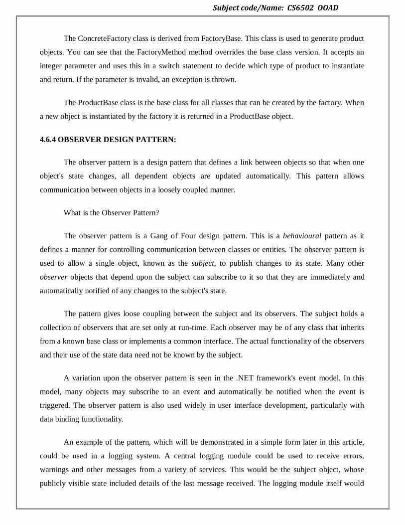
Subject code/Name: CS6502 OOAD
The ConcreteFactory class is derived from FactoryBase. This class is used to generate product
objects. You can see that the FactoryMethod method overrides the base class version. It accepts an
integer parameter and uses this in a switch statement to decide which type of product to instantiate
and return. If the parameter is invalid, an exception is thrown.
The ProductBase class is the base class for all classes that can be created by the factory. When
a new object is instantiated by the factory it is returned in a ProductBase object.
4.6.4 OBSERVER DESIGN PATTERN:
The observer pattern is a design pattern that defines a link between objects so that when one
object's state changes, all dependent objects are updated automatically. This pattern allows
communication between objects in a loosely coupled manner.
What is the Observer Pattern?
The observer pattern is a Gang of Four design pattern. This is a behavioural pattern as it
defines a manner for controlling communication between classes or entities. The observer pattern is
used to allow a single object, known as the subject, to publish changes to its state. Many other
observer objects that depend upon the subject can subscribe to it so that they are immediately and
automatically notified of any changes to the subject's state.
The pattern gives loose coupling between the subject and its observers. The subject holds a
collection of observers that are set only at run-time. Each observer may be of any class that inherits
from a known base class or implements a common interface. The actual functionality of the observers
and their use of the state data need not be known by the subject.
A variation upon the observer pattern is seen in the .NET framework's event model. In this
model, many objects may subscribe to an event and automatically be notified when the event is
triggered. The observer pattern is also used widely in user interface development, particularly with
data binding functionality.
An example of the pattern, which will be demonstrated in a simple form later in this article,
could be used in a logging system. A central logging module could be used to receive errors,
warnings and other messages from a variety of services. This would be the subject object, whose
publicly visible state included details of the last message received. The logging module itself would
Subject code/Name: CS6502 OOAD
not perform any additional processing of the messages received. Instead, it would raise a notification
to its observers for each new message.
The observers in this example could be varied in functionality but all would receive the same
notifications. There could be an observer that formatted the last message into an email and sent this to
an administrator. Another observer may store the message in the server's event log. A third could
record it in a database. In each case, the subject object would be unaware of the actions being
undertaken. The observers in use could be selected by a user at run-time or via a configuration system
to allow control of the logger's behaviour without modification to the source code.
Implementing the Observer Pattern
The UML class diagram above describes an implementation of the observer design pattern.
The items in the diagram are described below:
SubjectBase. This is the abstract base class for concrete subjects. It contains a private
collection of the observers that are subscribed to a subject and methods to allow new subscriptions to
be added and existing ones to be removed. It also includes a method that can be called by concrete
subjects to notify their observers of state changes. This Notify method loops through all of the
registered observers, calling their Update methods.
ConcreteSubject. Each concrete subject maintains its own state. When a change is made to
that state, the object calls the base class's Notify method to indicate this to all of its observers. As the
functionality of the observers is unknown, the concrete subjects also provide the means for the
observers to read the updated state, in this case via a GetState method.
Subject code/Name: CS6502 OOAD
ObserverBase. This is the abstract base class for all observers. It defines a method to be
called when the subject's state changes. In many cases this Update method will be abstract, in which
case you may decide to implement the base class as an interface instead.
ConcreteObserver. The concrete observer objects are the subscribers that react to changes in
the subject's state. When the Update method for an observer is called, it examines the subject to
determine which information has changed. It can then take appropriate action.
UNIT V
CODING AND TESTING
5.1 MAPPING DESIGN TO CODE:
OO development is iterative
OOA/D artifacts feed into implementation model in a traceable manner
Some tools generate partial code from UML
But programming not trivial generation!
Programmers make changes as the work out the details
Therefore, Expect and plan for change and deviation from design during programming
Mapping Designs to Code
Write source code for:
– Class and interface definitions
– Method definitions
Work from OOA/D artifacts
– Create class definitions for Domain Class Diagrams (DCDs)
– Create methods from Interaction diagrams
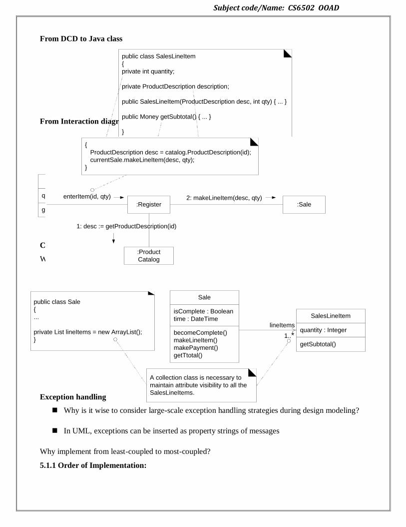
Subject code/Name: CS6502 OOAD
From DCD to Java class
From Interaction diagram to method
Collection classes
What collection class has been added to the design and why?
Exception handling
Why is it wise to consider large-scale exception handling strategies during design modeling?
In UML, exceptions can be inserted as property strings of messages
Why implement from least-coupled to most-coupled?
5.1.1 Order of Implementation:
public class SalesLineItem
{
private int quantity;
private ProductDescription description;
public SalesLineItem(ProductDescription desc, int qty) { ... }
public Money getSubtotal() { ... }
}
SalesLineItem
quantity : Integer
getSubtotal() : Money
ProductDescription
description : Text
price : Money
itemID : ItemID
...
1
description
2: makeLineItem(desc, qty)enterItem(id, qty)
1: desc := getProductDescription(id)
:Register :Sale
:Product
Catalog
{
ProductDescription desc = catalog.ProductDescription(id);
currentSale.makeLineItem(desc, qty);
}
SalesLineItem
quantity : Integer
getSubtotal()
1..*
Sale
isComplete : Boolean
time : DateTime
becomeComplete()
makeLineItem()
makePayment()
getTtotal()
public class Sale
{
...
private List lineItems = new ArrayList();
}
A collection class is necessary to
maintain attribute visibility to all the
SalesLineItems.
lineItems

Subject code/Name: CS6502 OOAD
5.2 TESTING:
Testing is a continuous activity during software development. In object-oriented systems,
testing encompasses three levels, namely, unit testing, subsystem testing, and system testing.
Unit Testing
In unit testing, the individual classes are tested. It is seen whether the class attributes are
implemented as per design and whether the methods and the interfaces are error-free. Unit testing is
the responsibility of the application engineer who implements the structure.
5.2.1 Issues in OO Testing:
Traditional systems define a unit as the smallest component that can be compiled and executed.
5.2.2 Units for OO Testing
Traditional systems define a unit as the smallest component that can be compiled and executed. Units
are normally a component which in theory is only ever assigned to one programmer
Two options for selecting units in object orientated systems:
Treat each class as a unit
Treat each method within a class as a unit
Advantages for Object Orientated Unit Testing
Once a class is testing thoroughly it can be reused without being unit tested again
UML class state charts can help with selection of test cases for classes
Classes easily mirror units in traditional software testing
Disadvantages for Object Orientated Unit Testing
Classes obvious unit choice, but they can be large in some applications
SalesLineItem
quantity : Integer
getSubtotal()
ProductCatalog
...
getProductDesc(...)
ProductDescription
description : Text
price : Money
itemID : ItemID
...
Store
address : Address
name : Text
addSale(...)
Payment
amount : Money
...
1..*
1..*
Register
...
endSale()
enterItem(...)
makeNewSale()
makePayment(...)
Sale
isComplete : Boolean
time : DateTime
becomeComplete()
makeLineItem(...)
makePayment(...)
getTotal()
...
1
1
1
1
1
1
*1
23
4
56
7
Subject code/Name: CS6502 OOAD
Problems dealing with polymorphism and inheritance
5.2.3 Implications of Composition, Encapsulation, Inheritance and Polymorphism
Composition Issues:
Objective of OO is to facilitate easy code reuse in the form of classes
To allow this each class has to be rigiriously unit tested
Due to classes potentially used in unforeseeable ways when composed in new systems
Example: A XML parser for a web browser
Classes must be created in a way promoting loose coupling and strong cohesion
Encapsulation Issues:
Encapsulation requires that classes are only aware of their own properties, and are able to operate
independently
If unit testing is performed well, the integration testing becomes more important
If you do not have access to source code then structural testing can be impossible
If you violate encapsulation for testing purposes, then the validity of test could be questionable
Inheritance Issues:
Inheritance is an important part of the object oriented paradigm
Unit testing a class with a super class can be impossible to do without the super classes
methods/variables
One Solution - Flattening
Merge the super class, and the class under test so all methods/variables are available
Solves initial unit test problems I Problems:
The class won‘t be flattened in the final product so potential issues may still arise
Complicated when dealing with multiple inheritance
Polymorphism Issues:
Repeatedly testing same methods
Time can then be wasted if not addressed
Potentially can be avoided, and actually save time.
5.2.4 Levels of Object Orientated Test
There are generally 3 or 4 levels of testing for object orientated systems depending on your
approach, consisting of:
1. Method Testing (Unit Testing)
2. Class Testing (Unit Testing/Intra class Testing)
3. Interclass Testing (Integration Testing)
Subject code/Name: CS6502 OOAD
4. System Testing
5.3 CLASS TESTING:
CRC Cards: Check that all collaborations are properly represented.
- Example: in a point of sale system.
- A read credit card responsibility of a credit sale class is accomplished if satisfied by a credit card
collaborator
Have you tested your analysis and design?
- If not, who will do it?
These steps are applied iteratively to each class and are applied iteratively to each class and through
each evolution of the OOA model.
5.3.1 Conventional Testing:
1. Identify each test case uniquely
- Associate test case explicitly with the class and/or method to be tested
2. State the purpose of the test 3.
3. Each test case should contain:
a. list of specified states for the object that is to be tested
b. A list of messages and operations that will be exercised as a consequence of
the test
c. A list of external conditions for setup (i.e., changes in the environment
External to the software that must exist in order to properly conduct the test)
d. Supplementary information that will aid in understanding or implementing the test
- Automated unit testing tools facilitate these requirements.
Challenges of Class Testing:
OO class is the target for test case design.
Encapsulation:
- Difficult to obtain a snapshot of a class without building extra methods which display the
classes state
Inheritance and polymorphism:
- Each new context of use (subclass) requires re-testing because a method may be
implemented differently (polymorphism).
Subject code/Name: CS6502 OOAD
- Other unaltered methods within the subclass may use the redefined method and need to be
tested
White box tests:
- Basis path, condition and loop tests can all apply to individual methods, but don‘t test
interactions between methods
5.4 OO INTEGRATION TESTING:
Object-oriented software development is an evolutionary process, and hence the opportunities
for integration are abundant. Conceptually, classes are encapsulation of data attributes and their
associated functions.
. A complete software system is also an aggregation of software components. All of these
various integration levels warrant contemporary integration techniques.
Traditional integration techniques towards the end of software development process do not
suffice any more.
Integration strategies are needed at class level, component level, sub-system level, and system
levels. Classes require integration of methods. Various types of class interaction mechanisms demand
different testing strategies. Integration of classes into components presses its own integration
requirements.
Integration testing – object-oriented perspective
The term integration testing has diversified meanings. Our definition of integration testing
resembles closely to the one given by Beizer .Integration testing is the testing performed to catch any
errors when two or more individually developed components are aggregated to execute their
functionalities.
A careful reader will notice that this is different than system testing, which we call as
integrated system testing. Examples of integration testing errors include internal and external
interface errors, timing errors, throughput errors, etc.
In integrated system testing, however, the typical errors include operating system call errors,
performance errors, partition errors, etc.
Over beck identifies three types of typical integration testing strategies.
1. Execution based integration testing to reveal erroneous interaction of units by tracing its
execution.
2. Value based integration testing employs certain values to execute units‘ interaction.
Boundary value testing and equivalent class partitioning testing strategies fall under this category.

Subject code/Name: CS6502 OOAD
3. Function based integration testing validates the functionality of components while they
interact.
Integration is typically defined as a process by which components are aggregated to create
larges components. In traditional software, the primary objective of integration testing of two
procedures A and B, which have both passed their unit tests, is to show inconsistencies between
them.
One can identify the following possible levels of integration in object-oriented context:
• Integration of methods into a single class.
• Integration of two or more classes through inheritance.
• Integration of two classes through containment.
• Integration of more than one class to form a component.
• Integration of components into a single application.
Structural integration testing
Stroustrup points out those classes do not exist in isolation. Rather they collaborate with other
classes to perform meaningful tasks. This collection of collaborating classes is known as a
component.
This section focuses on this structural combination of classes. There are various possible
means of class collaboration. The scope of a collaborating class may be at a method level, or at a
class level.
Method-level scope implies that an instance of the collaborating class is either constructed or
passed as a parameter in a method of the collaborative class. An appropriate call is then made to the
collaborating class.
Finally, that instance may be destructed, if constructed within the method, before the end of
the method. Class-level collaboration, on the other hand, implies that an instance of a collaborating
class is declared as an attribute of a collaborative class, hence a containment relationship.
There are various possibilities for these two basic forms of collaborations. For example, some
people might argue that private inheritance is one form of collaboration.
Functional integration testing
A fundamental question during integration testing is about the order of objects integration.
There are various possible orders of integration. Propose a simple order of integration that requires
minimal stub generation. Integration strategy consists of a virtual integration engine. There are two
queued inputs to this integration engine.

Subject code/Name: CS6502 OOAD
One queue contains the use-cases associated with the project, or with the application. The
other queue contains the usable objects. The virtual engine can either be built, or a person can play
the integration engine role.
The order of integration of objects depends upon the order of use-cases. We propose the
following set of activities for functional integration.
5.5 GUI TESTING:
GUI testing approaches
– Manual testing
– Static analysis
– Automated GUI testing tools
• Capture/Replay testing tools
• Random testing
• Unit testing
• Model-Based testing
GUI Testing raises specific challenges
GUI test automation is harder than API test automation
– Documentation; GUIs are slower that APIs
• Observing visible GUI state is difficult
• Observing invisible GUI state is tricky almost impossible
• Controlling GUI actions is difficult
– Event based
– Non-solicited events
– How to simulate user actions?
• State space and test case explosion
– Multiple ways (mouse, keyboard,…) to achieve the same goal
– Almost all user actions are enabled most of the time
GUI Errors:
Correct functioning
• Missing commands
• Correct window modality
• Mandatory fields
• Incorrect field defaults
• Data validation
Subject code/Name: CS6502 OOAD
• Error handling (messages to the user)
• Wrong values retrieved by queries
• Fill order
Manual Testing:
Heuristic Methods
– A group of specialists studies the SW in order to find problems that they can identify
Guidelines
– Recommendations about the SW and UI. E.g.,: how to organize the display and the menu
structure Cognitive walkthrough
– The developers walk through the SW in the context of core tasks a typical user will need to
accomplish.
The actions and the feedback of the interface are compared to the user‘s goals and
knowledge, and discrepancies between user‘s expectations and the steps required by the
interface are noted
Usability tests
– The SW is studied under real-world or controlled conditions (real users), with evaluators
gathering data on problems that rise during its use.
Advantages
– More bugs found per test cases executed (good specialist) (not necessarily by time or money
invested)
– Adaptability: bugs found provide hints to find other bugs
– Can find bugs that are difficult to find with automated tests (the converse is also true) • Usability
problems
– Can be supported / made more systematic/repeatable by checklists of standard tests and application
specific tests
– Good for exploratory / initial testing
Disadvantages
– Regression testing
– Effort required
– Weak coverage
– Repeatability / reproducibility
– Good test specialists are difficult to find
– Depends on the capabilities of the tester

Subject code/Name: CS6502 OOAD
Static code analysis:
Lightweight ―intellisense‖-like checking
– Check that guidelines are followed, e.g.,
• Button placement
• Use only colours which are distinguishable by colourblind users
– Check that UI components are used appropriately
• E.g., button without a Click event handler
Automated Testing Approaches:
Capture-Replay tools
• E.g., WinRunner, Rational Robot, Android
Random input testing tools
• E.g., Rational‘s TestFactory uses dumb monkey method
Unit testing frameworks
• E.g., JUnit, NUnit
Model-based testing tools
• E.g., Spec Explorer (extended) • E.g., Guitar (for GUI testing)
Model based GUI-Testing:
Advantages
– Higher degree of automation (test case generation)
– Allows more exhaustive testing
– Good for correctness/functional testing
– Model can be easily adapted to changes
Disadvantages
– Requires a formal specification/model
– Test case explosion
– Test case generation has to be controlled appropriately to generate a test case of manageable size
– Small changes to the model can result in a totally different test suite.
5.6 OO SYSTEM TESTING:
System Testing
– Tests the system as a whole
– Concerned with what happens
– Not how it happens – Black box
Object Oriented System Testing:
Subject code/Name: CS6502 OOAD
Almost identical to normal System Testing
• Except for generation of test cases
• UML can be used to generate test cases
UML (Unified Modelling Language):
Standard for designing and modelling systems
Consists of many different diagrams
– Structure diagrams (Class, Object, Component etc.)
– Behaviour diagrams (Use Case, Activity, State Machine etc.)
– Interaction diagrams (Sequence, Communication, Timing etc.)
UML diagrams can be used to develop
– Program Prototypes
– Use Cases (Functional requirements)
– Test Cases
• Potentially used for automated testing
– Research area.
Generating Test Cases
• Use UML description
– Generate list of System Functions
• Generate & Expand Use Cases
– High Level Use Cases (HLUC)
– Essential Use Cases (EUC)
– Expanded Essential Use Cases (EEUC)
– Real Use Cases (RUC)
• Generate Test Cases from Real Use Cases
Currency Converter:
Converts US Dollars to:
– Brazilian real (R$)
– Canadian dollars (C$)
– European Union euros (€)
– Japanese yen (¥)
• User can revise inputs
• User can perform repeated conversions
Summary:

Subject code/Name: CS6502 OOAD
System Testing
– Tests the system as a whole
– OO System Testing identical to normal System Testing
• Unified Modelling Language (UML)
– Used to describe OO applications
– Used to create test cases
5.6.1 Recovery Testing:
Recovery testing is a type of non-functional testing technique performed in order to determine how
quickly the system can recover after it has gone through system crash or hardware failure. Recovery
testing is the forced failure of the software to verify if the recovery is successful.
Recovery Plan - Steps:
Determining the feasibility of the recovery process.
Verification of the backup facilities.
Ensuring proper steps are documented to verify the compatibility of backup facilities.
Providing Training within the team.
Demonstrating the ability of the organization to recover from all critical failures.
Maintaining and updating the recovery plan at regular intervals.
5.6.2 Security Testing:
Security testing is a testing technique to determine if an information system protects data and
maintains functionality as intended. It also aims at verifying 6 basic principles as listed below:
Confidentiality
Integrity
Authentication
Authorization
Availability
Non-repudiation
Security Testing - Techniques:
Injection
Broken Authentication and Session Management
Cross-Site Scripting (XSS)
Insecure Direct Object References
Security Misconfiguration
Sensitive Data Exposure
Missing Function Level Access Control
Cross-Site Request Forgery (CSRF)
Using Components with Known Vulnerabilities
Subject code/Name: CS6502 OOAD
Unvalidated Redirects and Forwards
5.6.3 Stress Testing
Stress testing a Non-Functional testing technique that is performed as part of performance testing.
During stress testing, the system is monitored after subjecting the system to overload to ensure that
the system can sustain the stress.
The recovery of the system from such phase (after stress) is very critical as it is highly likely to
happen in production environment.
Reasons for conducting Stress Testing:
It allows the test team to monitor system performance during failures.
To verify if the system has saved the data before crashing or NOT.
To verify if the system prints meaning error messages while crashing or did it print some
random exceptions.
To verify if unexpected failures do not cause security issues.
Stress Testing - Scenarios:
Monitor the system behaviour when maximum number of users logged in at the same time.
All users performing the critical operations at the same time.
All users Accessing the same file at the same time.
Hardware issues such as database server down or some of the servers in a server park crashed
5.6.4 Performance Testing:
Performance testing, a non-functional testing technique performed to determine the system
parameters in terms of responsiveness and stability under various workload. Performance testing
measures the quality attributes of the system, such as scalability, reliability and resource usage.
Performance Testing Techniques:
Load testing - It is the simplest form of testing conducted to understand the behaviour of the system
under a specific load. Load testing will result in measuring important business critical transactions
and load on the database, application server, etc., are also monitored.
Stress testing - It is performed to find the upper limit capacity of the system and also to determine
how the system performs if the current load goes well above the expected maximum.
Soak testing - Soak Testing also known as endurance testing, is performed to determine the system
parameters under continuous expected load. During soak tests the parameters such as memory
utilization is monitored to detect memory leaks or other performance issues. The main aim is to
discover the system's performance under sustained use.
Spike testing - Spike testing is performed by increasing the number of users suddenly by a very large
amount and measuring the performance of the system. The main aim is to determine whether the
system will be able to sustain the workload.


