
CR100-CRMSystem BoardUser’s Manual
A19100133

CopyrightThis publication contains information that is protected by copyright. No part of it may be reproduced in any form or by any means or used to make any transfor-mation/adaptation without the prior written permission from the copyright hold-ers.
This publication is provided for informational purposes only. The manufacturer makes no representations or warranties with respect to the contents or use of this manual and specifically disclaims any express or implied warranties of merchantability or fitness for any particular purpose. The user will assume the entire risk of the use or the results of the use of this document. Further, the manufacturer reserves the right to revise this publication and make changes to its contents at any time, without obligation to notify any person or entity of such revisions or changes.
© 2012. All Rights Reserved.
TrademarksAll trademarks and registered trademarks of products appearing in this manual are the properties of their respective holders.

FCC and DOC Statement on Class BThis equipment has been tested and found to comply with the limits for a Class B digital device, pursuant to Part 15 of the FCC rules. These limits are designed to provide reasonable protection against harmful interference when the equipment is operated in a residential installation. This equipment generates, uses and can radiate radio frequency energy and, if not installed and used in accordance with the instruction manual, may cause harmful interference to radio communications. However, there is no guarantee that interference will not occur in a particular installation. If this equipment does cause harmful interference to radio or televi-sion reception, which can be determined by turning the equipment off and on, the user is encouraged to try to correct the interference by one or more of the following measures:
• Reorient or relocate the receiving antenna.• Increase the separation between the equipment and the receiver.• Connect the equipment into an outlet on a circuit different from that to which
the receiver is connected.• Consult the dealer or an experienced radio TV technician for help.
Notice:
1. The changes or modifications not expressly approved by the party responsible for compliance could void the user’s authority to operate the equipment.
2. Shielded interface cables must be used in order to comply with the emission limits.

1
4
Introduction
Table of Contents
Copyright ........................................................................................... 2
Trademarks ........................................................................................ 2
FCC and DOC Statement on Class B .............................................. 3
About this Manual ............................................................................. 6
Warranty .......................................................................................... 6
Static Electricity Precautions ............................................................. 7
Safety Measures ................................................................................. 7
About the Package ............................................................................ 8
Before Using the System Board ........................................................ 8
Chapter 1 - Introduction .................................................................. 9
Specifications .................................................................................. 9Features ...................................................................................... 12
Chapter 2 - Hardware Installation .................................................. 15
System Board Layout .................................................................... 15System Memory ........................................................................... 16
Installing the DIM Module ......................................................... 17CPU ............................................................................................ 19
Installing the CPU .................................................................... 19Installing the Fan and Heat Sink ................................................ 21
Jumper Settings ............................................................................. 23Clear CMOS Data ..................................................................... 23PS/2 Power Select .................................................................... 24USB Power Select ..................................................................... 25Panel Power Select ................................................................... 26COM1/COM2 RS232/RS422/RS485 Select.................................... 27COM1/COM2 RS232/Power Select............................................... 28Power-on Select ....................................................................... 29CompactFlash Card Setting ....................................................... 30
Rear Panel I/O Ports ..................................................................... 31PS/2 Mouse and PS/2 Keyboard Ports ......................................... 32COM (Serial) Ports ................................................................... 33HDMI Port ............................................................................... 34DVI-I Port ............................................................................... 35RJ45 LAN Ports ........................................................................ 36

1
5
Introduction
USB Ports................................................................................ 37Audio ...................................................................................... 39
I/O Connectors ............................................................................ 41S/PDIF Connector ..................................................................... 41LVDS LCD Panel Connector ........................................................ 42LCD/Inverter Power Connector ................................................... 42Digital I/O Connectors .............................................................. 44SATA (Serial ATA) Connectors .................................................... 45Cooling Fan Connectors ............................................................. 46Chassis Instrusion Connector .................................................... 47Power Connectors .................................................................... 48Standby Power LED .................................................................. 49Front Panel Connectors ............................................................. 50Expansion Slots ....................................................................... 51Battery ................................................................................... 54
Chapter 3 - BIOS Setup .................................................................. 56
Overview ..............................................................................................................56AMI BIOS Setup Utility ................................................................. 58
Main ....................................................................................... 58Advanced ................................................................................ 59Chipset ................................................................................... 79Boot ....................................................................................... 87Security .................................................................................. 89Save & Exit ............................................................................. 90
Updating the BIOS ........................................................................ 91
Chapter 4 - Supported Software ................................................... 92
Chapter 5 - RAID ........................................................................ 125
RAID Levels .......................................................................................................125Settings ................................................................................................................126
Chapter 6 - Intel AMT Settings ................................................... 130
Overview ............................................................................................................130Enable Intel® AMT in the AMI BIOS ............................................................131Enable Intel® AMT in the Intel® Management Engine BIOS Extension (MEBX) Screen ..............................................................................133
Appendix A - NLITE and AHCI Installation Guide ....................... 158
Appendix B - Watchdog Sample Code ......................................... 170
Appendix C - System Error Message ............................................ 171
Appendix D - Troubleshooting ...................................................... 173

1
6
Introduction
About this ManualAn electronic file of this manual is included in the CD. To view the user’s manual in the CD, insert the CD into a CD-ROM drive. The autorun screen (Main Board Utility CD) will appear. Click “User’s Manual” on the main menu.
Warranty 1. Warranty does not cover damages or failures that arised from misuse of the
product, inability to use the product, unauthorized replacement or alteration of components and product specifications.
2. The warranty is void if the product has been subjected to physical abuse, improper installation, modification, accidents or unauthorized repair of the product.
3. Unless otherwise instructed in this user’s manual, the user may not, under any circumstances, attempt to perform service, adjustments or repairs on the product, whether in or out of warranty. It must be returned to the purchase point, factory or authorized service agency for all such work.
4. We will not be liable for any indirect, special, incidental or consequencial damages to the product that has been modified or altered.

1
7
Introduction
Static Electricity PrecautionsIt is quite easy to inadvertently damage your PC, system board, components or devices even before installing them in your system unit. Static electrical dis-charge can damage computer components without causing any signs of physical damage. You must take extra care in handling them to ensure against electro-static build-up.
1. To prevent electrostatic build-up, leave the system board in its anti-static bag until you are ready to install it.
2. Wear an antistatic wrist strap.
3. Do all preparation work on a static-free surface.
4. Hold the device only by its edges. Be careful not to touch any of the compo-nents, contacts or connections.
5. Avoid touching the pins or contacts on all modules and connectors. Hold modules or connectors by their ends.
Important:Electrostatic discharge (ESD) can damage your processor, disk drive and other components. Perform the upgrade instruction procedures described at an ESD workstation only. If such a station is not available, you can provide some ESD protection by wearing an antistatic wrist strap and attaching it to a metal part of the system chassis. If a wrist strap is unavailable, establish and maintain contact with the system chassis throughout any procedures requiring ESD protection.
Safety MeasuresTo avoid damage to the system:• Use the correct AC input voltage range.
To reduce the risk of electric shock: • Unplug the power cord before removing the system chassis cover for instal-
lation or servicing. After installation or servicing, cover the system chassis before plugging the power cord.
Battery:• Danger of explosion if battery incorrectly replaced.• Replace only with the same or equivalent type recommend by the manufac-
turer.• Dispose of used batteries according to local ordinance.

1
8
Introduction
About the PackageThe system board package contains the following items. If any of these items are missing or damaged, please contact your dealer or sales representative for as-sistance.
One CR100-CRM board Two Serial ATA data cables Two COM port cables Two USB port cables One I/O shield One DVD One QR (Quick Reference)
Optional Items USB port cable COM port cable Serial ATA data cable Serial ATA power cable I/O shield
The system board and accessories in the package may not come similar to the information listed above. This may differ in accordance to the sales region or models in which it was sold. For more information about the standard package in your region, please contact your dealer or sales representative.
Before Using the System BoardBefore using the system board, prepare basic system components.
If you are installing the system board in a new system, you will need at least the following internal components.
• A CPU• Memory module• Storage devices such as hard disk drive, CD-ROM, etc.
You will also need external system peripherals you intend to use which will nor-mally include at least a keyboard, a mouse and a video display monitor.

1
9
Introduction
Processor
ChipsetSystem Memory
Expansion Slots
Chapter 1 - Introduction
• Socket G2 988B for: - 3rd Generation Intel® CoreTM processors (22nm process
technology) : Intel® Core™ i7-3610QE (6M Cache, up to 3.3 GHz); 45W : Intel® Core™ i5-3610ME (3M Cache, up to 3.3 GHz); 35W : Intel® Core™ i3-3120ME (3M Cache, 2.4 GHz); 35W - 2nd Generation Intel® CoreTM processors (32nm process
technology) : Intel® Core™ i7-2710QE (6M Cache, up to 3.0 GHz); 45W : Intel® Core™ i5-2510E (3M Cache, up to 3.1 GHz); 35W : Intel® Core™ i3-2330E (3M Cache, 2.2 GHz); 35W : Intel® Celeron® B810 (2M Cache, 1.6 GHz); 35W
• Intel® QM77 Express chipset• Two 204-pin SODIMM sockets• Supports DDR3 SODIMM
3rd Generation Processors 2nd Generation Processors
DDR3 1066/1333/1600MHz DDR3 1066 /1333MHz ( i 5 /Celeron)
DDR3 1600MHz (i7)
• Supports DDR3L SODIMM - 1066/1333MHz when operating at 1.35V - 1066/1333/1600MHz when operating at 1.5V• Supports dual channel memory interface• Supports up to 16GB system memory• DRAM device technologies: 1Gb, 2Gb and 4Gb DDR3 DRAM
technologies are supported for x8 and x16 devices, unbuf-fered, non-ECC
• 1 PCIe x16 slot - Supports Gen 3.0 (3rd generation processors) - Supports Gen 2.0 (2nd generation processors) - Configurations (supported only via a riser card): : One x8 (GFX) and two x4 (I/O) : Two x8 (GFX, I/O) : One x16 (GFX, I/O)• 2 PCIe x1 gold fingers for customized expansion (PCI or
Mini PCIe via a riser card• 1 Mini PCIe x1 slot (PCIe and USB signals)
Specifications

1
10
Introduction
Graphics
Audio
LAN
Serial ATA
Intel Active Management Technology (AMT)
TPM (optional)
USB interface
Rear Panel I/O Ports
• Intel® HD Graphics• Display ports: HDMI, 2 DVI-I (1 supports DVI-D signal
only), and LVDS • Display resolution up to 1920x1200• LVDS: Single Channel - 18/24-bit; Dual Channel - 36/48-bit• Intel® Clear Video Technology• DirectX Video Acceleration (DXVA) for accelerating video
processing - Full AVC/VC1/MPEG2 HW Decode• Supports DirectX 11/10.1/10/9 and OpenGL 3.0
• Realtek ALC886 5.1-channel High Defi nition Audio• Audio outputs: Mic-in/Center+Subwoofer, line-in/surround and
line-out• S/PDIF audio interface
• Intel® WG82579LM with iAMT8.0 Gigabit Ethernet Phy• Intel® WG82574L PCI Express Gigabit Ethernet controller• Integrated 10/100/1000 transceiver• Fully compliant with IEEE 802.3, IEEE 802.3u, IEEE 802.3ab• Supports wire management
• 4 Serial ATA ports - 2 SATA 3.0 ports with data transfer rate up to 6Gb/s - 2 SATA 2.0 ports with data transfer rate up to 3Gb/s• Integrated Advanced Host Controller Interface (AHCI) con-
troller• Supports RAID 0/1/5/10• Supports iAMT8.0• Out-of-band system access• Remote troubleshooting and recovery• Hardware-based agent presence checking• Proactive alerting• Remote hardware and software asset tracking• Provides a Trusted PC for secure transactions• Provides software license protection, enforcement and
password protection• XHCI Host Controller supports up to 4 super speed USB 3.0
ports• 1 mini-DIN-6 port for PS/2 mouse/keyboard• 4 USB 3.0/2.0/1.1 ports• 2 USB 2.0/1.1 ports• 1 DB-9 serial port - Supports RS232/422/485 (RS232 and/or Power)• 1 HDMI port• 2 DVI-I ports (1 supports DVI-D signal only)• 2 RJ45 LAN ports• Mic-in/Center+Subwoofer, line-in/surround and line out
jacks

1
11
Introduction
I/O Connectors
BIOS
Energy Efficient Design
Damage Free Intelligence
Temperature
Humidity
Dimensions
• 2 connectors for 4 external USB 2.0/1.1 ports• 5 connectors for 5 external serial ports - 1 RS232/422/485 (RS232 and/or Power) - 4 RS232• 1 LVDS LCD panel connector• 1 LCD/inverter power connector• 1 8-bit Digital I/O connector• 1 front audio connector for line-out and mic-in jacks• 1 S/PDIF connector• 4 Serial ATA ports (2 SATA 3.0; 2 SATA 2.0)• 1 24-pin ATX power connector• 1 chassis intrusion connector• 1 front panel connector• 2 fan connectors• AMI BIOS• 64Mbit SPI BIOS• Supports ErP Lot6 power saving (optional)• ACPI v3.0 specification• System Power Management• Wake-On-Events include: - Wake-On-PS/2 KB/Mouse - Wake-On-USB KB/Mouse - Wake-On-LAN - RTC timer to power-on the system• AC power failure recovery• Monitors CPU/system temperature and overheat alarm• Monitors VCORE/1.05V/DDR/3.3V/5V/12V voltages and fail-
ure alarm• Monitors CPU/system fan speed and failure alarm• Read back capability that displays temperature, voltage and
fan speed• Watchdog timer function - Watchdog timeout programmable via software from 1 to
255 seconds• Operating: 0oC to 60oC• Storage: -20oC to 85oC• 10% to 90%• Mini-ITX form factor• 170mm (6.7”) x 170mm (6.7”)

1
12
Introduction
Features
Watchdog Timer
The Watchdog Timer function allows your application to regularly “clear” the sys-tem at the set time interval. If the system hangs or fails to function, it will reset at the set time interval so that your system will continue to operate.
DDR3
DDR3 delivers increased system bandwidth and improved performance. It offers peak data transfer rate of up to 21 Gb/s bandwidth. The advantages of DDR3 are its higher bandwidth and its increase in performance at a lower power than DDR2.
Graphics
The integrated Intel HD graphics for graphics intensive applications delivers ex-ceptional 3D, 2D and video capabilities. It supports HDMI, DVI-I and LVDS inter-faces.
DVI
DVI (Digital Visual Interface) is a form of video interface technology made to maximize the quality of flat panel LCD monitors and modern video graphics cards. Data is transmitted using the TMDS (Transition Minimized Differential Sig-naling) protocol, providing a digital signal from the PC’s graphics subsystem to the display.
PCI Express
PCI Express is a high bandwidth I/O infrastructure that possesses the ability to scale speeds by forming multiple lanes. The PCI Express architecture provides a high performance graphics infrastructure by enhancing the capability of a x16 PCI Express lane to provide 4 Gigabytes per second transfer rate.
Intel Active Management Technology (AMT)
Intel Active Management Technology (Intel® AMT) allows remote access and man-agement of networked systems even while PCs are powered off, remotely repair systems after OS failures and has the capability to remotely update all systems with the latest security software.
Audio
The Realtek ALC886 audio codec provides 5.1-channel High Definition audio out-put.

1
13
Introduction
Serial ATA
Serial ATA is a storage interface that is compliant with SATA 1.0a specifica-tion. SATA 3.0 supports speed up to 6Gb/s while SATA 2.0 supports speed up to 3Gb/s. This improves hard drive performance faster than the standard parallel ATA whose data transfer rate is 100MB/s. The board supports RAID 0/1/5/10.
Gigabit LAN
The Intel WG82579LM PHY and Intel WG82574L PCI Express Gigabit controllers support up to 1Gbps data transmission.
USB
The system board supports the new USB 3.0. It is capable of running at a maxi-mum transmission speed of up to 5 Gbit/s (625 MB/s) and is faster than USB 2.0 (480 Mbit/s, or 60 MB/s) and USB 1.1 (12Mb/s). USB 3.0 reduces the time re-quired for data transmission, reduces power consumption, and is backward com-patible with USB 2.0. It is a marked improvement in device transfer speeds between your computer and a wide range of simultaneously accessible exter-nal Plug and Play peripherals.
Wake-On-LAN
This feature allows the network to remotely wake up a Soft Power Down (Soft-Off) PC. It is supported via the onboard LAN port or via a PCI LAN card that uses the PCI PME (Power Management Event) signal. However, if your system is in the Suspend mode, you can power-on the system only through an IRQ or DMA inter-rupt.
Important:The 5V_standby power source of your power supply must support ≥720mA.
Wake-On-PS/2
This function allows you to use the PS/2 keyboard or PS/2 mouse to power-on the system.
Important:The 5V_standby power source of your power supply must support ≥720mA.

1
14
Introduction
Wake-On-USB
This function allows you to use a USB keyboard or USB mouse to wake up a sys-tem from the S3 (STR - Suspend To RAM) state.
Important:If you are using the Wake-On-USB Keyboard/Mouse function for 2 USB ports, the 5V_standby power source of your power supply must support ≥1.5A. For 3 or more USB ports, the 5V_standby power source of your power supply must support ≥2A.
RTC Timer
The RTC installed on the system board allows your system to automatically pow-er-on on the set date and time.
ACPI STR
The system board is designed to meet the ACPI (Advanced Configuration and Power Interface) specification. ACPI has energy saving features that enables PCs to implement Power Management and Plug-and-Play with operating systems that support OS Direct Power Management. ACPI when enabled in the Power Manage-ment Setup will allow you to use the Suspend to RAM function.
With the Suspend to RAM function enabled, you can power-off the system at once by pressing the power button or selecting “Standby” when you shut down Windows® without having to go through the sometimes tiresome process of closing files, applications and operating system. This is because the system is capable of storing all programs and data files during the entire operating session into RAM (Random Access Memory) when it powers-off. The operating session will resume exactly where you left off the next time you power-on the system.
Important:The 5V_standby power source of your power supply must support 720mA.
Power Failure Recovery
When power returns after an AC power failure, you may choose to either power-on the system manually or let the system power-on automatically.

15
2Hardware Installation
System Board Layout
Chapter 2 - Hardware Installation
(Top
: D
VI-
D s
igna
l onl
y)
1 5
JP1
LAN 2USB3.0 (2-3)
6
LAN 1
2
PS/2Mouse/KB
USB 8USB 9
COM 1HDMI
Line-in/ SurroundLine-outMic-in/ Center+Subwoofer
DVI-IDVI-I
1
COM612
COM512
COM412
COM312 13 24
Power-onselect ( )JP7
1
9 9 9 9 121 ATX Power
DIO
12
19
1
11
Frontpanel
SPI Flash BIOS1
System fan
Battery
1
Panel powerselect ( )JP9
5
IntelQM77
6
2
StandbyPower LED
Clear CMOS(JP10)
SATA 3.0
1
910
9
SATA 4
SATA 5
SATA 0
SATA 1
SATA 2.0USB 6-7
USB 4-5
1
1
1
1
1
LCD/Inverterpower
LVDS LCDpanel
40 39
2 1
S/PDIF1
Socket G2rPGA 988B
1
CPU fan
USB 0-1/ 2-3 powerselect (JP6)1
DDR3_2 SODIMM
DDR3_1 SODIMM
12
56
1 Chassisintrusion
12
56
1
2
5
6
12
910
Front audio
PCIe x16
PCIe x1 PCIe x1
COM1 RS232/422/485select ( )JP4
PS/2 powerselect (JP2)
USB 8-9 powerselect ( )JP8
COM2 RS232/422/485 Select(JP5)
COM2 RS232/Powerselect (JP3)
12
12
COM1 RS232/Powerselect (JP1)
1
Backlightlevel (JP11)
Mini PCIe
USB 2.0
1
Buzzer
COM2
12
9
1 ON2SW1
USB 2.0
USB3.0 (0-1)

16
2Hardware Installation
System Memory
Important:Electrostatic discharge (ESD) can damage your system board, processor, disk drives, add-in boards, and other components. Perform the upgrade instruction procedures described at an ESD workstation only. If such a station is not available, you can provide some ESD protection by wearing an antistatic wrist strap and attaching it to a metal part of the system chassis. If a wrist strap is unavailable, establish and maintain contact with the system chassis throughout any procedures requiring ESD pro-tection.
DDR3-2
DDR3-1
Standby Power LED
Important:When the Standby Power LED lit red, it indicates that there is power on the system board. Power-off the PC then unplug the power cord prior to installing any devices. Failure to do so will cause severe damage to the motherboard and components.
Features
• Two 204-pin DDR3 SODIMM sockets
• Supports 1066/1333/1600MHz DDR3 SDRAM
• Dual channel memory interface
• Supports maximum of 16GB system memory
17
2Hardware Installation
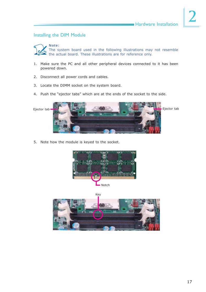
Note:The system board used in the following illustrations may not resemble the actual board. These illustrations are for reference only.
Installing the DIM Module
1. Make sure the PC and all other peripheral devices connected to it has been powered down.
2. Disconnect all power cords and cables.
3. Locate the DIMM socket on the system board.
4. Push the “ejector tabs” which are at the ends of the socket to the side.
Ejector tabEjector tab
5. Note how the module is keyed to the socket.
Key
Notch

18
2Hardware Installation
7. Seat the module vertically, pressing it down fi rmly until it is completely seat-ed in the socket. The ejector tabs at the ends of the socket will automatically snap into the locked position to hold the module in place.
6. Grasping the module by its edges, position the module above the socket with the “notch” in the module aligned with the “key” on the socket. The keying mechanism ensures the module can be plugged into the socket in only one way.
19
2Hardware Installation
CPU
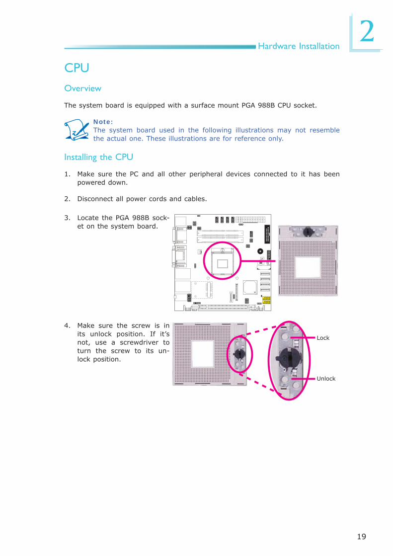
Overview
The system board is equipped with a surface mount PGA 988B CPU socket.
Note:The system board used in the following illustrations may not resemble the actual one. These illustrations are for reference only.
Installing the CPU
1. Make sure the PC and all other peripheral devices connected to it has been powered down.
2. Disconnect all power cords and cables.
3. Locate the PGA 988B sock-et on the system board.
4. Make sure the screw is in its unlock position. If it’s not, use a screwdriver to turn the screw to its un-lock position.
Lock
Unlock

20
2Hardware Installation
5. Position the CPU above the socket. The gold triangular mark on the CPU must align with pin 1 of the CPU socket.
Important:Handle the CPU by its edg-es and avoid touching the pins. Pin 1
Gold triangular mark
6. Insert the CPU into the socket until it is seated in place. The CPU will fi t in only one orientation and can easily be inserted without exerting any force. Use a screwdriver to turn the screw to its lock posi-tion.
Important:Do not force the CPU into the socket. Forcing the CPU into the socket may bend the pins and damage the CPU.
Screw in locked position

21
2Hardware Installation
Installing the Fan and Heat Sink
The CPU must be kept cool by using a CPU fan with heat sink. Without suffi cient air circulation across the CPU and heat sink, the CPU will overheat damaging both the CPU and system board.
Note:• Use only certifi ed fan and heat sink.• Your fan and heat sink package usually contains the fan and heat sink
assembly, and an installation guide. If the installation procedure in the installation guide differs from the one in this section, please follow the installation guide in the package.
1. On the solder side of the board, match the retention module base to the mounting holes around the CPU socket.
Retention module base
2. Turn to the component side of the board making sure the retention module base is positioned and fi tted properly under the board.
3. Apply a thin layer of thermal paste on top of the CPU. Do not spread the paste all over the surface. When you later place the heat sink on top, the compound will disperse evenly.

22
2Hardware Installation
5. Connect the CPU fan’s cable connector to the CPU fan connector on the sys-tem board.
Mounting screw
4. Place the fan / heat sink assembly on top of the CPU. The 4 screws around the heat sink must match the screw holes of the retention module base. We strongly recommend using this type of fan / heat sink assembly because it provides adequate cooling to the components of the system board.
Turn each Phillips head screw half way down fi rst to initially stabilize the heat sink onto the board, then fi nally tighten each screw.
Important: Do not turn the fi rst screw all the way down followed by the next and so on. This is to avoid imbalance which might cause cracks or fractures to the CPU and/or heat sink assembly.
CPU fan cable

23
2Hardware Installation
Jumper Settings
Clear CMOS Data
If you encounter the following,
a) CMOS data becomes corrupted.b) You forgot the supervisor or user password.
you can reconfi gure the system with the default values stored in the ROM BIOS.
To load the default values stored in the ROM BIOS, please follow the steps below.
1. Power-off the system and unplug the power cord.
2. Set JP10 pins 2 and 3 to On. Wait for a few seconds and set JP10 back to its default setting, pins 1 and 2 On.
3. Now plug the power cord and power-on the system.
JP10
2-3 On: Clear CMOS Data
1-2 On: Normal(default)
31 2 31 2

24
2Hardware Installation
JP2 is used to select the power of the PS/2 keyboard and PS/2 mouse ports. Se-lecting +5V_standby will allow you to use the PS/2 keyboard or PS/2 mouse to wake up the system.
PS/2 Power Select
JP2
2-3 On: +5V_standby
1-2 On: +5V(default)
Important:The +5VSB power source of your power supply must support ≥720mA.
1
32
1
32

25
2Hardware Installation
This jumper is used to select the power of the USB ports. Selecting +5V_standby will allow you to use a USB device to wake up the system.
Important:If you are using the Wake-On-USB Keyboard/Mouse function for 2 USB ports, the +5V_standby power source of your power supply must sup-port ≥1.5A. For 3 or more USB ports, the +5V_standby power source of your power supply must support ≥2A.
USB Power Select
USB 0-1/2-3(JP6)
2-3 On: +5V_standby
1-2 On: +5V(default)
1
32
1
32USB 8-9
(JP8)
2-3 On: +5V_standby
1-2 On: +5V(default)
1
3
21
3
2

26
2Hardware Installation
Panel Power Select
1-2 On: +12V
135
246
3-4 On: +5V
135
246
5-6 On: +3.3V(default)
135
246
JP9
JP9 is used to select the power supplied to the LCD panel.
Important:Before powering-on the system, make sure JP9’s setting matches the LCD panel’s specifi cation. Selecting the incorrect voltage will seriously damage the LCD panel.

27
2Hardware Installation
COM1/COM2 RS232/RS422/RS485 Select
5-6 On: RS485
JP4 (for COM1) and JP5 (for COM2) are used to confi gure the COM ports to RS232, RS422 (Full Duplex) or RS485.
The pin function of the COM ports will vary according to the jumper’s setting.
JP4/JP5
642
531
COM 1
COM 2JP4
JP5
RS232 RS422Full Duplex
RS485
COM 1
DCD
-
TDRD
DTR
-G
ND
1 2 3 4 5
RTS-
RI-
DSR-
CTS
-
6 7 8 9
DAT
A+
N.C
.D
ATA-
N.C
.N
.C.
1 2 3 4 5
N.C
.
N.C
.
N.C
.
N.C
.
6 7 8 9
RXD
+
TXD
+RXD
-
TXD
-N
.C.
1 2 3 4 5
N.C
.
N.C
.
N.C
.
N.C
.
6 7 8 9
642
5311-2 On: RS232
(default)3-4 On: RS422
Full Duplex
642
531

28
2Hardware Installation
COM1/COM2 RS232/Power Select
JP1
JP3
2 4 6
1 3 5
2 4 6
1 3 5
1-3, 2-4 On: RS232 (default)
3-5 (+12V), 4-6 (+5V) On: RS232 with power
1-3, 2-4 On: RS232 (default)
3-5 (+12V), 4-6 (+5V) On: RS232 with power
2
1 3 5
4 6
1 3 5
2 4 6

29
2Hardware Installation
Power-on Select
To power-on via WOL after G3:
1. Set JP7 pins 2 and 3 to On.
2. Set the “After G3” fi eld to Power Off/WOL.
3. Set the “GbE Wake Up From S5” to Enabled.
The BIOS fi elds are in the “South Bridge Confi guration” submenu (Chipset menu) of the AMI BIOS utility.
To power-on via AC Power:
1. Set JP7 pins 2 and 3 to On.
2. Set the “After G3” fi eld to Power On.
1-2 On: Power-on via power button(default)
2-3 On: Power-on via AC power; or Power-on via WOL after G3
JP731 2
31 2

30
2Hardware Installation
JP 11
Backlight Level Select
JP 11 is used to select the backlight level +5V or +3.3V.
3
12
3
1
2
2-3 On: +3.3V
1-2 On: +5V (default)
31
2Hardware Installation
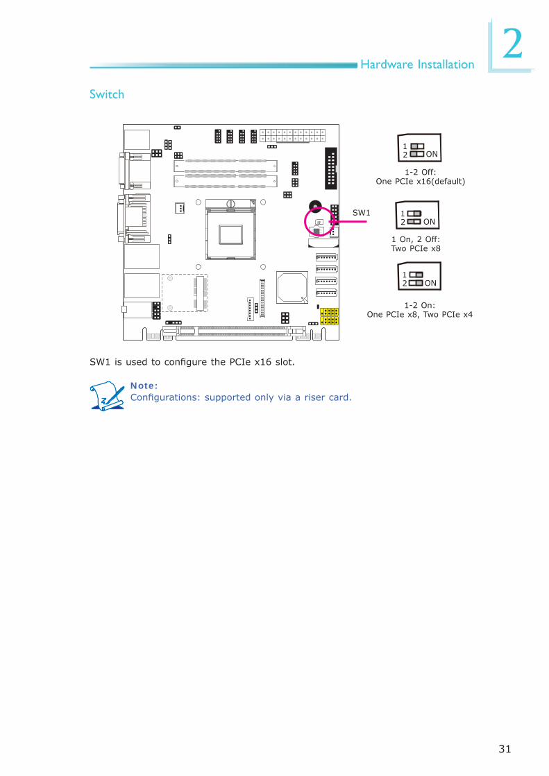
Switch
SW1
12 ON
12 ON
12 ON
1-2 Off: One PCIe x16(default)
1-2 On: One PCIe x8, Two PCIe x4
SW1 is used to confi gure the PCIe x16 slot.
1 On, 2 Off: Two PCIe x8
Note:Confi gurations: supported only via a riser card.

32
2Hardware Installation
Rear Panel I/O Ports
The rear panel I/O ports consist of the following:
• PS/2 mouse/keyboard port• COM port• DVI-I port • DVI-I port (DVI-D signal only)• 2 Intel LAN ports• 4 USB ports• Line-out jack• Line-in jack• Mic-in jack
HDMI USB 3.0USB 3.0
Line-out
Line-in
Mic-in
PS/2 K/B Mouse LANCOM 1
DVI-I
LAN
USB 2.0
DVI-I (DVI-D signal only)

33
2Hardware Installation
PS/2 Mouse and PS/2 Keyboard Ports
These ports are used to connect a PS/2 mouse and a PS/2 keyboard. The PS/2 mouse port uses IRQ12.
Wake-On-PS/2 Keyboard/Mouse
The Wake-On-PS/2 Keyboard/Mouse function allows you to use the PS/2 key-board or PS/2 mouse to power-on the system. To use this function:
• Jumper Setting
JP2 must be set to “2-3 On: +5V_standby”. Refer to “PS/2 Power Select” in this chapter for more information.
• BIOS Setting
Confi gure the PS/2 keyboard/mouse wake up function in the Advanced menu (“ACPI Power Management Confi guration” submenu) of the BIOS. Refer to chapter 3 for more information.
Important:The +5V_standby power source of your power supply must support ≥720mA.
PS/2 Keyboard/Mouse

34
2Hardware Installation
COM (Serial) Ports
COM 1
COM 3 to COM 6 are fi xed at RS232.
The pin function of COM 1 and COM 2 ports will vary according to JP4/JP5’s set-ting. Refer to “COM1/COM2 RS232/RS422/RS485 Select” in this chapter for more information.
The serial ports are asynchronous communication ports with 16C550A-compatible UARTs that can be used with modems, serial printers, remote display terminals, and other serial devices.
Connecting External Serial Ports
Your COM port may come mounted on a card-edge bracket. Install the card-edge bracket to an available slot at the rear of the system chassis then insert the se-rial port cable to the COM connector. Make sure the colored stripe on the ribbon cable is aligned with pin 1 of the COM connector.
BIOS Setting
Confi gure the serial ports in the Advanced menu (“Super IO Confi guration” sub-menu) of the BIOS. Refer to chapter 3 for more information.
COM 4COM 3COM 5
COM 6
COM 1: RS232/422/485
COM 3 to COM 6: RS232
12
9
DCD-TDGNDRTS-RI-
RDDTR-DSR-CTS-
COM 2
12
9
DCD-TDGNDRTS-RI-
RDDTR-DSR-CTS-COM 2:
RS232/422/485

35
2Hardware Installation
HDMI
Graphics Interface
The HDMI port which carries both digital audio and video signals is used to con-nect a LCD monitor or digital TV that has the HDMI port.
DVI-I(DVI-D signal only)
DVI-I
The display ports consist of the following:
• HDMI• LVDS• DVI-I port • DVI-I port (DVI-D signal only)
Note:The system board supports 3 independent displays. If you are connect-ing 3 display devices, make sure 2 of the devices are connected to the HDMI and DVI (-D signal) interfaces.
HDMI Port

36
2Hardware Installation
DVI-I Port
The DVI-I port is used to connect an LCD monitor. This port supports DVI-D sig-nal only.
Connect the display device’s cable connector to the DVI-I port. After you plug the cable connector into the port, gently tighten the cable screws to hold the connec-tor in place.
BIOS Setting
Confi gure the display device in the Chipset menu (“North Bridge Confi guration” submenu) of the BIOS. Refer to chapter 3 for more information.

37
2Hardware Installation
RJ45 LAN Ports
The LAN ports allow the system board to connect to a local area network by means of a network hub.
BIOS Setting
Confi gure the onboard LAN in the Chipset menu (“South Bridge Confi guration” submenu) of the BIOS. Refer to chapter 3 for more information.
Driver Installation
Install the LAN drivers. Refer to chapter 4 for more information.
LAN 1
LAN 2
Features
• Intel 82579LM with iAMT8.0 Gigabit LAN Phy
• Intel 82574L PCI Express Gigabit LAN controller

38
2Hardware Installation
USB Ports
USB allows data exchange between your computer and a wide range of simulta-neously accessible external Plug and Play peripherals.
The system board is equipped with four onboard USB 3.0/2.0/1.1 ports (USB 0-3) and two onboard USB 2.0/1.1 ports (USB 8-9). The two 10-pin connectors allow you to connect 4 additional USB 2.0/1.1 ports (USB 4-7). The additional USB ports may be mounted on a card-edge bracket. Install the card-edge bracket to an available slot at the rear of the system chassis and then insert the USB port cables to a connector.
BIOS Setting
Confi gure the onboard USB in the Advanced menu (“USB Confi guration” sub-menu) of the BIOS. Refer to chapter 3 for more information.
Driver Installation
You may need to install the proper drivers in your operating system to use the USB device. Refer to your operating system’s manual or documentation for more information.
USB 6-7USB 4-5
USB 0
USB 1
USB 3
USB 2
10
VCC
-Dat
a+
Dat
aG
ND
Key
VCC
-Dat
a+
Dat
aG
ND
N.
C.
9 12
USB 9
USB 8
USB 2.0
USB 3.0
USB 3.0
USB 2.0

39
2Hardware Installation
Wake-On-USB Keyboard/Mouse
The Wake-On-USB Keyboard/Mouse function allows you to use a USB keyboard or USB mouse to wake up a system from the S3 (STR - Suspend To RAM) state. To use this function:
• Jumper Setting
JP6 must be set to “2-3 On: +5V_standby”. Refer to “USB Power Select” in this chapter for more information.
Important:If you are using the Wake-On-USB Keyboard/Mouse function for 2 USB ports, the +5V_standby power source of your power supply must sup-port ≥1.5A. For 3 or more USB ports, the +5V_standby power source of your power supply must support ≥2A.

40
2Hardware Installation
Audio
Rear Audio
The system board is equipped with 3 audio jacks. A jack is a one-hole connecting interface for inserting a plug.
• Mic-in Jack (Pink) This jack is used to connect an external microphone.
• Line-in Jack (Light Blue) This jack is used to connect any audio devices such as Hi-fi set, CD player,
tape player, AM/FM radio tuner, synthesizer, etc.
• Line-out Jack (Lime) This jack is used to connect a headphone or external speakers.
Front Audio
The front audio connector allows you to connect to the second line-out and mic-in jacks that are at the front panel of your system.
Line-out
Line-in
Mic-in
Rear audio
Front audio
1Mic2-L
Line2-RFront_IO_Sense
GNDPresence Signal
Key
2
10
Mic2-JD
Line2-JD9
Mic2-R
Line2-L

41
2Hardware Installation
BIOS Setting
Confi gure the onboard audio in the Chipset menu (“South Bridge” submenu) of the BIOS. Refer to chapter 3 for more information.
Driver Installation
Install the audio driver. Refer to chapter 4 for more information.

42
2Hardware Installation
S/PDIF Connector
The S/PDIF connector is used to connect an external S/PDIF port. Your S/PDIF port may be mounted on a card-edge bracket. Install the card-edge bracket to an available slot at the rear of the system chassis then connect the audio cable to the S/PDIF connector. Make sure pin 1 of the audio cable is aligned with pin 1 of the S/PDIF connector.
1 5
+5V
KeySPDIF out
GroundSPDIF in
I/O Connectors

43
2Hardware Installation
LVDS LCD Panel ConnectorLCD/Inverter Power Connector
The system board allows you to connect a LCD Display Panel by means of the LVDS LCD panel connector and the LCD/Inverter power connector. These connec-tors transmit video signals and power from the system board to the LCD Display Panel.
Refer to the next page for the pin functions of these connectors.
BIOS Setting
Confi gure the LCD panel in the Advanced Chipset Features submenu of the BIOS. Refer to chapter 3 for more information.
2 1
LVDS LCD panel
40 39
8
1
LCD/Inverter power

44
2Hardware Installation
Pins13579111315171921232527293133353739
FunctionGND
LVDS_Out3+LVDS_Out3-
GNDLVDS_Out2+LVDS_Out2-
GNDLVDS_Out1+LVDS_Out1-
GNDLVDS_Out0+LVDS_Out0-
GNDLVDS_CLK1+LVDS_CLK1-
GNDLVDS_DDCCLKLVDS_DDCDAA
Panel PowerPanel Power
Pins246810121416182022242628303234363840
FunctionGND
LVDS_Out7+LVDS_Out7-
GNDLVDS_Out6+LVDS_Out6-
GNDLVDS_Out5+LVDS_Out5-
GNDLVDS_Out4+LVDS_Out4-
GNDLVDS_CLK2+LVDS_CLK2-
GNDN. C.N. C.
Panel PowerPanel Power
LVDS LCD Panel Connector
LCD/Inverter Power Connector
Pins12345678
FunctionGNDGNDPanel Inverter Brightness Voltage ControlPanel Power+3.3VPanel Backlight On/Off Control+12V+12V

45
2Hardware Installation
Digital I/O Connectors
The 8-bit Digital I/O connector provides powering-on function to external devices that are connected to these connectors.
2 1
19
Pin Pin Assignment Pin Pin Assignment
1 GND 2 +12V
3 DIO7 4 +12V
5 DIO6 6 GND
7 DIO5 8 VCC
9 DIO4 10 VCC
11 DIO3 12 GND
13 DIO2 14 V_5P0_STBY
15 DIO1 16 V_5P0_STBY
17 DIO0 18 GND
19 GND

46
2Hardware Installation
SATA 0
The Serial ATA connectors are used to connect Serial ATA devices. Connect one end of the Serial ATA cable to a SATA connector and the other end to your Serial ATA device.
BIOS Setting
Confi gure the Serial ATA drives in the Advanced menu (“IDE Confi guration” sub-menu) of the BIOS. Refer to chapter 3 for more information.
SATA (Serial ATA) Connectors
7
RXN
GN
D
TXP
TXN
GN
D
1
RXP
GN
D
SATA 2.0 3Gb/s
SATA 3.0 6Gb/s
Features
• 4 Serial ATA ports - 2 SATA2 ports with data transfer rate up to 3Gb/s - 2 SATA3 ports with data transfer rate up to 6Gb/s
• Integrated Advanced Host Controller Interface (AHCI) controller
• Supports RAID 0, RAID 1, RAID 5 and RAID 10
SATA 1
SATA 4
SATA 5

47
2Hardware Installation
Cooling Fan Connectors
The fan connectors are used to connect cooling fans. The cooling fans will provide adequate airfl ow throughout the chassis to prevent overheating the CPU and sys-tem board components.
BIOS Setting
The Advanced menu (“Hardware Health Confi guration” submenu) of the BIOS will display the current speed of the cooling fans. Refer to chapter 3 for more infor-mation.
System fan
CPU fan
1
3 SensePowerGround
3
1 GroundPowerSense

48
2Hardware Installation
Chassis Intrusion Connector
The board supports the chassis intrusion detection function. Connect the chas-sis intrusion sensor cable from the chassis to this connector. When the system’s power is on and a chassis intrusion occurred, an alarm will sound. When the system’s power is off and a chassis intrusion occurred, the alarm will sound only when the system restarts.
MyGuard Hardware Monitor
Install the “MyGuard Hardware Monitor” utility. By default, the chassis intrusion detection function is disabled. When enabled, a warning message will appear when the chassis is open. The utility can also be confi gured so that a beeping alarm will sound when the chassis is open. Refer to the “MyGuard Hardware Monitor” section in chapter 4 for more information.
1 2
Ground
Signal

49
2Hardware Installation
Power Connectors
Use a power supply that complies with the ATX12V Power Supply Design Guide Version 1.1. An ATX12V power supply unit has a standard 24-pin ATX main pow-er connector that must be inserted into the 24-pin connector.
The power connector from the power supply unit are designed to fi t the 24-pin connector in only one orientation. Make sure to fi nd the proper orientation before plugging the connectors.
The system board requires a minimum of 300 Watt power supply to operate. Your system confi guration (CPU power, amount of memory, add-in cards, peripherals, etc.) may exceed the minimum power requirement. To ensure that adequate power is provided, we strongly recommend that you use a minimum of 400 Watt (or greater) power supply.
Important:Insuffi cient power supplied to the system may result in instability or the add-in boards and peripherals not functioning properly. Calculating the system’s approximate power usage is important to ensure that the power supply meets the system’s consumption requirements.
13
1 12
24
+3.
3VD
C+
3.3V
DC
CO
M+
5VD
CCO
M+
5VD
CCO
MPW
R_O
K+
5VSB
+12
VD
C+
12VD
C+
3.3V
DC
+3.
3VD
C
-12V
DC
CO
MPS
_ON
#CO
MCO
MCO
M NC
+5V
DC
+5V
DC
+5V
DC
CO
M

50
2Hardware Installation
Standby Power LED
Standby Power LED
This LED will lit red when the system is in the standby mode. It indicates that there is power on the system board. Power-off the PC and then unplug the power cord prior to installing any devices. Failure to do so will cause severe damage to the motherboard and components.
51
2Hardware Installation
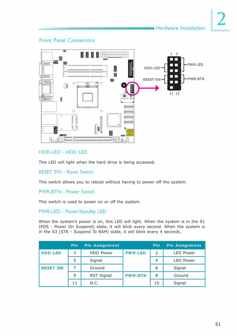
Front Panel Connectors
HDD-LED - HDD LED
This LED will light when the hard drive is being accessed.
RESET SW - Reset Switch
This switch allows you to reboot without having to power off the system.
PWR-BTN - Power Switch
This switch is used to power on or off the system.
PWR-LED - Power/Standby LED
When the system’s power is on, this LED will light. When the system is in the S1 (POS - Power On Suspend) state, it will blink every second. When the system is in the S3 (STR - Suspend To RAM) state, it will blink every 4 seconds.
HDD-LED
RESET-SW
PWR-LED
PWR-BTN
1211
21
Pin Pin Assignment Pin Pin Assignment
HDD-LED 3 HDD Power PWR-LED 2 LED Power
5 Signal 4 LED Power
RESET SW 7 Ground 6 Signal
9 RST Signal PWR-BTN 8 Ground
11 N.C. 10 Signal
52
2Hardware Installation
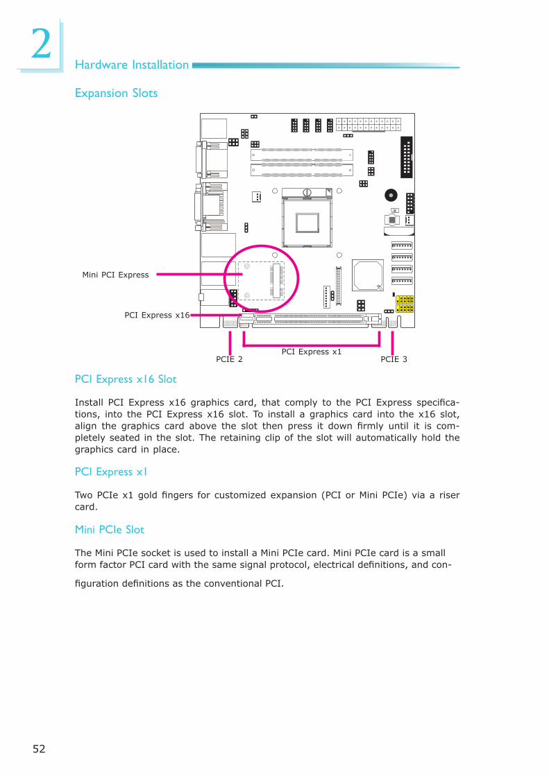
Expansion Slots
PCI Express x16 Slot
Install PCI Express x16 graphics card, that comply to the PCI Express specifi ca-tions, into the PCI Express x16 slot. To install a graphics card into the x16 slot, align the graphics card above the slot then press it down fi rmly until it is com-pletely seated in the slot. The retaining clip of the slot will automatically hold the graphics card in place.
PCI Express x1
Two PCIe x1 gold fi ngers for customized expansion (PCI or Mini PCIe) via a riser card.
PCI Express x16
PCI Express x1PCIE 2 PCIE 3
Mini PCI Express
Mini PCIe Slot
The Mini PCIe socket is used to install a Mini PCIe card. Mini PCIe card is a small form factor PCI card with the same signal protocol, electrical defi nitions, and con-
fi guration defi nitions as the conventional PCI.
53
2Hardware Installation
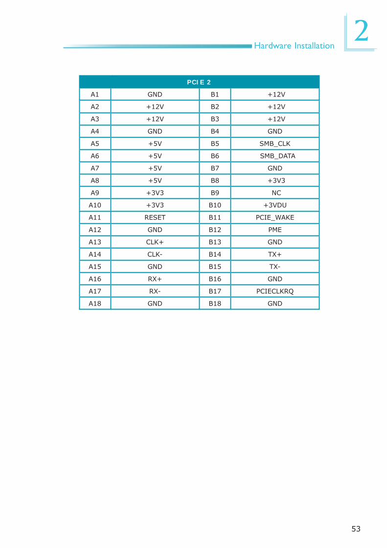
PCIE 2
A1 GND B1 +12V
A2 +12V B2 +12V
A3 +12V B3 +12V
A4 GND B4 GND
A5 +5V B5 SMB_CLK
A6 +5V B6 SMB_DATA
A7 +5V B7 GND
A8 +5V B8 +3V3
A9 +3V3 B9 NC
A10 +3V3 B10 +3VDU
A11 RESET B11 PCIE_WAKE
A12 GND B12 PME
A13 CLK+ B13 GND
A14 CLK- B14 TX+
A15 GND B15 TX-
A16 RX+ B16 GND
A17 RX- B17 PCIECLKRQ
A18 GND B18 GND

54
2Hardware Installation
PCIE 3
A1 GND B1 +12V
A2 +12V B2 +12V
A3 +12V B3 +12V
A4 GND B4 GND
A5 USB+ B5 SMB_CLK
A6 USB- B6 SMB_DATA
A7 +5V B7 GND
A8 +5V B8 +3V3
A9 +3V3 B9 NC
A10 +3V3 B10 +3VDU
A11 RESET B11 PCIE_WAKE
A12 GND B12 NC
A13 CLK+ B13 GND
A14 CLK- B14 TX+
A15 GND B15 TX-
A16 RX+ B16 GND
A17 RX- B17 PCIECLKRQ
A18 GND B18 GND

55
2Hardware Installation
The lithium ion battery powers the real-time clock and CMOS memory. It is an auxiliary source of power when the main power is shut off.
Safety Measures
• Danger of explosion if battery incorrectly replaced.
• Replace only with the same or equivalent type recommend by the manufac-turer.
• Dispose of used batteries according to local ordinance.
Battery
Battery

56
3BIOS Setup
Chapter 3 - BIOS Setup
Overview The BIOS is a program that takes care of the basic level of communication be-tween the CPU and peripherals. It contains codes for various advanced features found in this system board. The BIOS allows you to confi gure the system and save the confi guration in a battery-backed CMOS so that the data retains even when the power is off. In general, the information stored in the CMOS RAM of the EEPROM will stay unchanged unless a confi guration change has been made such as a hard drive replaced or a device added.
It is possible that the CMOS battery will fail causing CMOS data loss. If this hap-pens, you need to install a new CMOS battery and reconfi gure the BIOS settings.
Note:The BIOS is constantly updated to improve the performance of the sys-tem board; therefore the BIOS screens in this chapter may not appear the same as the actual one. These screens are for reference purpose only.
Default Configuration
Most of the confi guration settings are either predefi ned according to the Load Op-timal Defaults settings which are stored in the BIOS or are automatically detected and confi gured without requiring any actions. There are a few settings that you may need to change depending on your system confi guration.
Entering the BIOS Setup Utility
The BIOS Setup Utility can only be operated from the keyboard and all com-mands are keyboard commands. The commands are available at the right side of each setup screen.
The BIOS Setup Utility does not require an operating system to run. After you power up the system, the BIOS message appears on the screen and the memory count begins. After the memory test, the message “Press DEL to run setup” will appear on the screen. If the message disappears before you respond, restart the system or press the “Reset” button. You may also restart the system by pressing the <Ctrl> <Alt> and <Del> keys simultaneously.

57
3BIOS Setup
Legends
Keys
Right and Left arrows
Up and Down arrows
<Esc>
+ (plus key)
- (minus key)
Tab
<F1>
<Enter>
Function
Moves the highlight left or right to select a menu.
Moves the highlight up or down between submenus or fi elds.
Exits to the BIOS Setup Utility.
Scrolls forward through the values or options of the highlighted fi eld.
Scrolls backward through the values or options of the highlighted fi eld.
Selects a fi eld.
Displays General Help.
Press <Enter> to enter the high-lighted submenu.
Scroll Bar
When a scroll bar appears to the right of the setup screen, it indicates that there are more available fi elds not shown on the screen. Use the up and down arrow keys to scroll through all the available fi elds.
Submenu
When ““ appears on the left of a particular fi eld, it indicates that a submenu which contains additional options are available for that fi eld. To display the sub-menu, move the highlight to that fi eld and press <Enter>.

58
3BIOS Setup
MainThe Main menu is the fi rst screen that you will see when you enter the BIOS Setup Utility.
System Date
The date format is <day>, <month>, <date>, <year>. Day displays a day, from Sunday to Saturday. Month displays the month, from January to December. Date displays the date, from 1 to 31. Year displays the year, from 1980 to 2099.
System Time
The time format is <hour>, <minute>, <second>. The time is based on the 24-hour military-time clock. For example, 1 p.m. is 13:00:00. Hour displays hours from 00 to 23. Minute displays minutes from 00 to 59. Second displays seconds from 00 to 59.
Set the Date. Use Tab toswitch between Data elements.
Aptio Setup Utility - Copyright (C) 2011 American Megatrends, Inc.Save & ExitChipset
Version 2.14.1219. Copyright (C) 2011 American Megatrends, Inc.
Select Screen Select ItemEnter: Select+/-: Change Opt.F1: General HelpF2: Previous ValuesF3: Optimized DefaultsESC: Exit
BIOS InformationBIOS VendorCore VersionCompliencyProject VersionBuild Date and Time
System Language
System DateSystem Time
Access Level
American Megatrends4.6.5.1UEFI 2.1; PI 1.21APTJ 0.15 x6402/01/2012 10:37:24
[English]
[Wed 02/01/2012][23:12:27]
Administrator
Advanced Boot SecurityMain
AMI BIOS Setup Utility

59
3BIOS Setup
Advanced The Advanced menu allows you to confi gure your system for basic operation. Some entries are defaults required by the system board, while others, if enabled, will improve the performance of your system or let you set some features ac-cording to your preference.
Important: Setting incorrect fi eld values may cause the system to malfunction.
Set digital IO port as Input or Output (601)
Aptio Setup Utility - Copyright (C) 2011 American Megatrends, Inc.
Version 2.14.1219. Copyright (C) 2011 American Megatrends, Inc.
DDR3 Type Select ACPI Power Management Confi gurationTrusted ComputingPC Health StatusCPU Confi gurationSATA Confi gurationIntel TXT(LT) Confi gurationPCH-FW Confi gurationIntel(R) Anti-Theft Technology Confi gurationAMT Confi gurationUSB Confi gurationF81217 Second Super IO Confi gurationF71879 Super IO Confi gurationSerial Port Console RedirectionCPU PPM Confi guration
Save & ExitChipset Boot SecurityMain Advanced
Select Screen Select ItemEnter: Select+/-: Change Opt.F1: General HelpF2: Previous ValuesF3: Optimized DefaultsESC: Exit
[DDR3]
DDR3 Type Select
DDR3LDDR3

60
3BIOS Setup
ACPI Power Management Confi guration
This section is used to confi gure the ACPI Power Management.
Enables or Disables BIOS ACPI Auto Confi guration.
Aptio Setup Utility - Copyright (C) 2011 American Megatrends, Inc.
Version 2.14.1219. Copyright (C) 2011 American Megatrends, Inc.
ACPI Power Management Confi guration
Enable ACPI Auto Confi gurationACPI Sleep State
Resume by PMEResume by RTC Alarm
Advanced
[Disable][S3 (Suspend to RAM) ]
[Disabled][Disabled]
ACPI Sleep State
Selects the highest ACPI sleep state the system will enter when the Suspend button is pressed.
S1(POS) Enables the Power On Suspend function.
S3(STR) Enables the Suspend to RAM function.
Resume by PME
Enable this fi eld to use the PME signal to wake up the system.
Resume by RTC Alarm
When Enabled, the system uses the RTC to generate a wakeup event.
Select Screen Select ItemEnter: Select+/-: Change Opt.F1: General HelpF2: Previous ValuesF3: Optimized DefaultsESC: Exit

61
3BIOS Setup
Trusted Computing (optional)
This section confi gures settings relevant to Trusted Computing innovations.
Enables or Disables BIOS support for security device. O.S. will not show Security Device. TCG EFI protocol and INT1A interface will not be available.
Aptio Setup Utility - Copyright (C) 2011 American Megatrends, Inc.
Version 2.14.1219. Copyright (C) 2011 American Megatrends, Inc.
Confi guration TPM Support
Current Status Information
Advanced
TPM Support
Enables or Disables TPM. O.S. will not show TPM. Resetting the platform is required.
[Disabled]
Select Screen Select ItemEnter: Select+/-: Change Opt.F1: General HelpF2: Previous ValuesF3: Optimized DefaultsESC: Exit

62
3BIOS Setup
PC Health Status
This section displays the SIO hardware health monitor.
Aptio Setup Utility - Copyright (C) 2011 American Megatrends, Inc.
Version 2.14.1219. Copyright (C) 2011 American Megatrends, Inc.
Smart Fan Function Case Open Beep
CPU Temperature System Temperature CPU FAN Speed System FAN Speed VCore 1V05 DDR +3.3V +5.0V +12V
Advanced
[Disabled]
: +39 C: +37 C: 2555 RPM: N/A: +0.872V: +1.05V: +1.536V: +3.248 V: +4.912 V: +12.144 V Select Screen
Select ItemEnter: Select+/-: Change Opt.F1: General HelpF2: Previous ValuesF3: Optimized DefaultsESC: Exit
Aptio Setup Utility - Copyright (C) 2011 American Megatrends, Inc.
Version 2.14.1219. Copyright (C) 2011 American Megatrends, Inc.
Smart Fan Function CPU Smart Fan Control Boundary 1 Boundary 2 Boundary 3 Boundary 4 Speed Count 1 Speed Count 2 Speed Count 3 Speed Count 4 Speed Count 5
Advanced
[Automatic]7060504010075502510
Select Screen Select ItemEnter: Select+/-: Change Opt.F1: General HelpF2: Previous ValuesF3: Optimized DefaultsESC: Exit
Smart Fan Function
CPU Smart Fan Control
When this feature is set to Automatic, the CPU’s fan speed will rotate ac-cording to the CPU’s temperature. The higher the temperature, the faster the speed of rotation.
Smart Fan Function
Enable CPU SmartFan

63
3BIOS Setup
Boundary 1 to Boundary 4
The range is from 0-127.
Speed Count 1 to Speed Count 5
The range is from 1-100.
Case Open Beep
Set this fi eld to Enabled to allow the system to alert you of a chassis intru-sion event.

64
3BIOS Setup
CPU Confi guration
This section is used to confi gure the CPU. It will also display the detected CPU information.
Enabled for Windows XP and Linux (OS optimized for Hyper-Threading Technology) and Disabled for other OS (OS not optimized for Hyper-Threading Technology). When Disabled only one thread per enabled core is enabled.
Aptio Setup Utility - Copyright (C) 2011 American Megatrends, Inc.
Version 2.14.1219. Copyright (C) 2011 American Megatrends, Inc.
CPU Confi guration
Intel (R) Core (TM) i7-3610QE CPU @ 2.30GHzCPU SignatureMicrocode PatchMax CPU SpeedMin CPU SpeedCPU SpeedProcessor CoresIntel HT TechnologyIntel VT-x TechnologyIntel SMX Technology64-bit
L1 Data CacheL1 Code CacheL2 CacheL3 Cache
Hyper-threadingActive Processor CoresLimit CPUID MaximumIntel Virtualization Technology
Advanced
Hyper-threading
Enable this fi eld for Windows XP and Linux which are optimized for Hyper-Threading technology. Select disabled for other OSes not optimized for Hyper-Threading technology. When disabled, only one thread per enabled core is enabled.
Active Processor Cores
Number of cores to enable in each processor package.
Limit CPUID Maximum
The CPUID instruction of some newer CPUs will return a value greater than 3. The default is Disabled because this problem does not exist in the Win-dows series operating systems. If you are using an operating system other than Windows, this problem may occur. To avoid this problem, enable this fi eld to limit the return value to 3 or less than 3.
Intel Virtualization Technology
When this fi eld is set to Enabled, the VMM can utilize the additional hardware capabilities provided by Vanderpool Technology.
306a872300 MHz1200 MHz2300 MHz4SupportedSupportedSupportedSupported
32 kB x 432 kB x 4256kB x 46144 kB
[Enabled][All][Disabled][Disabled]
Select Screen Select ItemEnter: Select+/-: Change Opt.F1: General HelpF2: Previous ValuesF3: Optimized DefaultsESC: Exit

65
3BIOS Setup
SATA Confi guration
This section is used to confi gure SATA functions.
Enable or disable SATA Device.
Aptio Setup Utility - Copyright (C) 2011 American Megatrends, Inc.
Version 2.14.1219. Copyright (C) 2011 American Megatrends, Inc.
SATA Controller(s)SATA Mode SelectionSATA Test Mode
Serial ATA Port 0 Software PreserveSerial ATA Port 1 Software PreserveSerial ATA Port 4 Software PreserveSerial ATA Port 5 Software Preserve
Advanced
SATA Controller(s)
This fi eld is used to enable or disable the Serial ATA channels.
SATA Mode Selection
IDE Mode This option confi gures the Serial ATA drives as Parallel ATA storage devices.AHCI Mode This option allows the Serial ATA devices to use AHCI (Advanced Host Con-troller Interface).RAID Mode This option allows you to create RAID or Intel Matrix Storage confi guration on Serial ATA devices.
SATA Test Mode
This fi eld is used to enable or disable the Serial ATA test mode.
[Enabled][IDE][Enabled]
Hitachi HDT721 (1000.SupportedHitachi HDS722 (2000.SupportedEmptyUnknownATAPI iHAS32 ATAPIN/A Select Screen
Select ItemEnter: Select+/-: Change Opt.F1: General HelpF2: Previous ValuesF3: Optimized DefaultsESC: Exit

66
3BIOS Setup
If AHCI or RAID is selected in the SATA Mode Selection, it will display the follow-ing information:
Determines how SATA controller(s) operate.
Aptio Setup Utility - Copyright (C) 2011 American Megatrends, Inc.
Version 2.14.1219. Copyright (C) 2011 American Megatrends, Inc.
SATA Controller(s)SATA Mode SelectionSATA Test ModeAgressive LPM Support Software Feature Mask Confi guration
Serial ATA Port 0 Software Preserve Port 0 Hot Plug External SATA SATA Device Type Spin Up DeviceSerial ATA Port 1 Software Preserve Port 1 Hot Plug External SATA SATA Device Type Spin Up DeviceSerial ATA Port 4 Software Preserve Port 4 Hot Plug External SATA
Advanced
Serial ATA Port 0 to Serial ATA Port 5
These fi elds are used to confi gure the connected SATA devices.
[Enabled][AHCI][Disabled][Enabled]
Hitachi HDT721 (1000.Supported[Enabled][Disabled][Disabled][Hard Disk Driver][Disabled]Hitachi HDS 722 (2000.Supported[Enabled][Disabled][Disabled][Hard Disk Driver][Disabled]EmptyUnknown[Enabled][Disabled][Disabled]
Select Screen Select ItemEnter: Select+/-: Change Opt.F1: General HelpF2: Previous ValuesF3: Optimized DefaultsESC: Exit

67
3BIOS Setup
Software Feature Mask Confi guration
Aptio Setup Utility - Copyright (C) 2011 American Megatrends, Inc.
Version 2.14.1219. Copyright (C) 2011 American Megatrends, Inc.
RAID0RAID1RAID10RAID5Intel Rapid Recovery TechnologyOROM UI and BANNERHDD UnlockLED LocateIRRT only on eSATASmart Response TechnologyOROM UI Delay
Advanced
[Enabled][Enabled][Enabled][Enabled][Enabled][Enabled][Enabled][Enabled][Enabled][Enabled][2 Seconds]
Select Screen Select ItemEnter: Select+/-: Change Opt.F1: General HelpF2: Previous ValuesF3: Optimized DefaultsESC: Exit
Enable or disable RAID0 feature.
RAID0 to RAID5
Enables or disables RAID0 to RAID5 feature.
Intel Rapid Recovery Technology
Enables or disables Intel Rapid Recovery Technology.
OROM UI and BANNER
When enabled, the OROM UI is shown. When disabled, no OROM banner or information will be displayed if all disks and RAID volumes are Normal.
HDD Unlock
When enabled, it indicates that the HDD password unlock in the OS is ena-bled.
LED Locate
When enabled, it indicates that the LED/SGPIO hardware is attached and ping to locate feature is enabled on the OS.
IRRT only on eSATA
When enabled, only IRRT volumes can span internal and eSATA drives.
When disabled, any RAID volume can span internal and eSATA drives.

68
3BIOS Setup
Smart Response Technology
Enables or disables Smart Response Technology.
OROM UI Delay
When enabled, it indicates the delay of the OROM UI Splash Screen in a nor-mal status.
69
3BIOS Setup
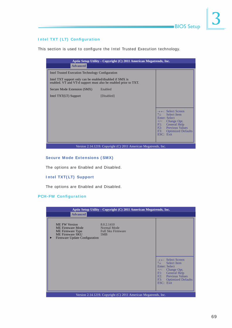
Intel TXT (LT) Confi guration
This section is used to confi gure the Intel Trusted Execution technology.
Secure Mode Extensions (SMX)
The options are Enabled and Disabled.
Intel TXT(LT) Support
The options are Enabled and Disabled.
PCH-FW Confi guration
Aptio Setup Utility - Copyright (C) 2011 American Megatrends, Inc.
Version 2.14.1219. Copyright (C) 2011 American Megatrends, Inc.
Intel Trusted Execution Technology Confi guration
Intel TXT support only can be enabled/disabled if SMX isenabled. VT and VT-d support must also be enabled prior to TXT.
Secure Mode Extension (SMX)
Intel TXT(LT) Support
Advanced
Enabled
[Disabled]
Select Screen Select ItemEnter: Select+/-: Change Opt.F1: General HelpF2: Previous ValuesF3: Optimized DefaultsESC: Exit
Aptio Setup Utility - Copyright (C) 2011 American Megatrends, Inc.
Version 2.14.1219. Copyright (C) 2011 American Megatrends, Inc.
ME FW Version ME Firmware Mode ME Firmware Type ME Firmware SKU Firmware Update Confi guration
Advanced
8.0.2.1410Normal ModeFull Sku Firmware5MB
Select Screen Select ItemEnter: Select+/-: Change Opt.F1: General HelpF2: Previous ValuesF3: Optimized DefaultsESC: Exit

70
3BIOS Setup
Intel Anti-Theft Confi guration
This section is used to disable the PC at the hardware level in the event of loss or theft.
Intel Anti-Theft Technology
The options are Enabled and Disabled.
Enter Intel AT Suspend Mode
The options are Enabled and Disabled.
Aptio Setup Utility - Copyright (C) 2011 American Megatrends, Inc.
Version 2.14.1219. Copyright (C) 2011 American Megatrends, Inc.
Intel Anti-Theft Technology Confi guration
Intel Anti-Theft TechnologyIntel Anti-Theft Technology RecoveEnter Intel AT Suspend Mode
Advanced
[Disabled]3[Disabled]
Select Screen Select ItemEnter: Select+/-: Change Opt.F1: General HelpF2: Previous ValuesF3: Optimized DefaultsESC: Exit
Enable/Disable Intel AT in BIOS for testing only.

71
3BIOS Setup
Intel AMT Confi guration
Enable/ Disable Intel (R) Active Management Technology BIOS Extension. Note: iAMT H/W is always enabled. This option just controls the BIOS extension execution. If enabled, this requires additional fi rmware in the SPI device.
Aptio Setup Utility - Copyright (C) 2011 American Megatrends, Inc.
Version 2.14.1219. Copyright (C) 2011 American Megatrends, Inc.
Intel AMT Un-Confi gure ME
Advanced
[Enabled][Disabled]
Intel AMT
Enables or disables the AMT function.
Un-Confi gure ME
Select Enabled to unconfi gure the ME function without the need for a pass-word.
Select Screen Select ItemEnter: Select+/-: Change Opt.F1: General HelpF2: Previous ValuesF3: Optimized DefaultsESC: Exit

72
3BIOS Setup
USB Confi guration
This section is used to confi gure USB.
Legacy USB Support
Enabled Enables legacy USB.Auto Disables support for legacy when no USB devices are connected.Disabled Keeps USB devices available only for EFI applications.
EHCI Hand-off
This is a workaround for OSes that does not support EHCI hand-off. The EHCI ownership change should be claimed by the EHCI driver.
USB transfer time-out
The time-out value for Bulk and Interrupt transfers.
Device reset time-out
Selects the USB mass storage device start unit command timeout.
Enables Legacy USB support. AUTO option disables legacy support if no USB devices are connected. DISABLE option will keep USB devices available only for EFI applications.
Aptio Setup Utility - Copyright (C) 2011 American Megatrends, Inc.
Version 2.14.1219. Copyright (C) 2011 American Megatrends, Inc.
USB Confi guration
USB Devices: 2 Drivers, 1 Keyboard, 1 mouse, 2 Hubs
Legacy USB SupportEHCI Hand-off
USB hardware delays and time-outs:USB transfer time-outDevice reset time-outDevice power-up delay
Mass Storage Devices:Seagate FreeAgent GoFlex 214TEAC USB UF000x 0.00
Advanced
[Enabled][Disabled]
[20 sec][20 sec][Auto]
[Auto][Auto]
Select Screen Select ItemEnter: Select+/-: Change Opt.F1: General HelpF2: Previous ValuesF3: Optimized DefaultsESC: Exit

73
3BIOS Setup
Device power-up delay
Maximum time the device will take before it properly reports itself to the Host Controller. “Auto” uses default value: for a Root port it is 100 ms, for a Hub port the delay is taken from Hub descriptor.

74
3BIOS Setup
Select an Optimal Setting for Super IO device
Aptio Setup Utility - Copyright (C) 2011 American Megatrends, Inc.
Version 2.14.1219. Copyright (C) 2011 American Megatrends, Inc.
Serial Port 4 Confi guration
Serial PortDevice Settings
Change Settings
Advanced
[Enabled]IO=228h; IRQ=11;
[Auto]
Serial Port 3 Confi guration to Serial Port 6 Confi guration
Select Screen Select ItemEnter: Select+/-: Change Opt.F1: General HelpF2: Previous ValuesF3: Optimized DefaultsESC: Exit
F81217 Second Super IO Confi guration
This section is used to confi gure the serial port functions.
Set Parameters of Serial Port 4 (COMB)
Aptio Setup Utility - Copyright (C) 2011 American Megatrends, Inc.
Version 2.14.1219. Copyright (C) 2011 American Megatrends, Inc.
F81217 Second Super IO Confi guration
F81217 Second Super IO ChipSerial Port 3 Confi gurationSerial Port 4 Confi gurationSerial Port 5 Confi gurationSerial Port 6 Confi guration
Advanced
F81217 Second IO
Select Screen Select ItemEnter: Select+/-: Change Opt.F1: General HelpF2: Previous ValuesF3: Optimized DefaultsESC: Exit
Serial Port
Enables or disables the serial port.
Change Settings
Selects the IO/IRQ setting of the I/O device.

75
3BIOS Setup
F71879 Super IO Confi guration
This section is used to confi gure the I/O functions supported by the onboard Super I/O chip.
Restore AC Power Loss help.
Aptio Setup Utility - Copyright (C) 2011 American Megatrends, Inc.
Version 2.14.1219. Copyright (C) 2011 American Megatrends, Inc.
F71879 Super IO Confi guration
F71879 Super IO Chip Restore AC Power Loss Watchdog Timer Super IO Watchingdog TimerSerial Port 1 Confi gurationSerial Port 2 Confi guration
Advanced
Fintek F71879[Power Off][Disabled]10
Select Screen Select ItemEnter: Select+/-: Change Opt.F1: General HelpF2: Previous ValuesF3: Optimized DefaultsESC: Exit
Restore AC Power Loss
OffWhen power returns after an AC power failure, the system’s power is off. You must press the Power button to power-on the system.OnWhen power returns after an AC power failure, the system will automatically power-on.Last StateWhen power returns after an AC power failure, the system will return to the state where you left off before power failure occurs. If the system’s power is off when AC power failure occurs, it will remain off when power returns. If the system’s power is on when AC power failure occurs, the system will power-on when power returns.
Watchdog Timer
Enable or disable Super I/O watchdog timer.
76
3BIOS Setup
Enable or Disable Serial Port (COM)
Aptio Setup Utility - Copyright (C) 2011 American Megatrends, Inc.
Version 2.14.1219. Copyright (C) 2011 American Megatrends, Inc.
Serial Port 1 Confi guration
Serial PortDevice Settings
Change Settings
Advanced
[Enabled]IO=3F8h; IRQ=4;
[Auto]
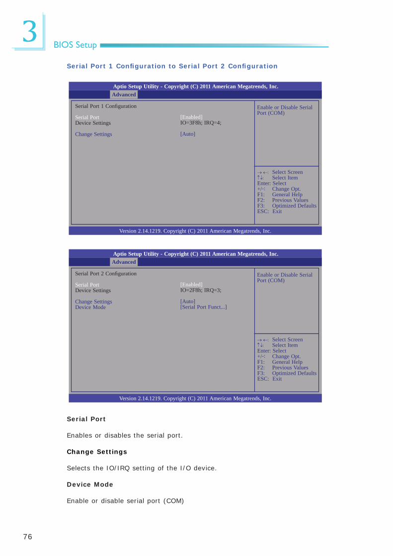
Serial Port 1 Confi guration to Serial Port 2 Confi guration
Select Screen Select ItemEnter: Select+/-: Change Opt.F1: General HelpF2: Previous ValuesF3: Optimized DefaultsESC: Exit
Serial Port
Enables or disables the serial port.
Change Settings
Selects the IO/IRQ setting of the I/O device.
Device Mode
Enable or disable serial port (COM)
Enable or Disable Serial Port (COM)
Aptio Setup Utility - Copyright (C) 2011 American Megatrends, Inc.
Version 2.14.1219. Copyright (C) 2011 American Megatrends, Inc.
Serial Port 2 Confi guration
Serial PortDevice Settings
Change SettingsDevice Mode
Advanced
[Enabled]IO=2F8h; IRQ=3;
[Auto][Serial Port Funct...]
Select Screen Select ItemEnter: Select+/-: Change Opt.F1: General HelpF2: Previous ValuesF3: Optimized DefaultsESC: Exit

77
3BIOS Setup
Serial Port Console Redirection
Console Redirection En-able or Disable.
Aptio Setup Utility - Copyright (C) 2011 American Megatrends, Inc.
Version 2.14.1219. Copyright (C) 2011 American Megatrends, Inc.
COM1 (Disabled) Console Redirection
COM2 (Pci Bus0, Dev0, Func0) (Disabled) Console Redirection
Serial Port for Out-of-Band Management/ Windows Emergency Management Service (EMS) Console RedirectionConsole Redirection Settings
Advanced
Port is Disabled
Port is Disabled
[Disabled]
Select Screen Select ItemEnter: Select+/-: Change Opt.F1: General HelpF2: Previous ValuesF3: Optimized DefaultsESC: Exit
Console Redirection Settings
The settings specify how the host computer and the remote computer (which the user is using) will exchange data. Both computers should have the same or the compatible settings.

78
3BIOS Setup
CPU PPM Confi guration
Enable/Disable Intel SpeedStep
Aptio Setup Utility - Copyright (C) 2011 American Megatrends, Inc.
Version 2.14.1219. Copyright (C) 2011 American Megatrends, Inc.
Sandybridge PPM Confi guration
EISTTurbo ModeCPU C3 ReportCPU C6 ReportCPU C7 ReportConfi g Top LockLong Duration Power LimitLong Duration MaintainedShort Duration Power LimitACPI T State
Advanced
[Enabled][Enabled][Enabled][Enabled][Enabled][Disabled]0280[Disabled]
Select Screen Select ItemEnter: Select+/-: Change Opt.F1: General HelpF2: Previous ValuesF3: Optimized DefaultsESC: Exit
EIST
This fi eld is used to enable or disable the Intel Enhanced SpeedStep Technol-ogy.
Turbo Mode
The options are Enabled and Disabled.
CPU C3 Report to CPU C7 Report
Enables or disables CPU C3 (ACPI C2), C6 and C7 (ACPI C3) report to OS.

79
3BIOS Setup
ChipsetConfi gures relevant chipset functions.
Aptio Setup Utility - Copyright (C) 2011 American Megatrends, Inc.
Version 2.14.1219. Copyright (C) 2011 American Megatrends, Inc.
PCH-IO Confi gurationSystem Agent (SA) Confi guration
Save & ExitAdvanced Boot SecurityMain Chipset
PCH Parameters
Select Screen Select ItemEnter: Select+/-: Change Opt.F1: General HelpF2: Previous ValuesF3: Optimized DefaultsESC: Exit

80
3BIOS Setup
PCH-IO Confi guration
PCI Express Coniguration settings.
Aptio Setup Utility - Copyright (C) 2011 American Megatrends, Inc.
Version 2.14.1219. Copyright (C) 2011 American Megatrends, Inc.
Intel PCH RC VersionIntel PCH SKU Name Intel PCH Rev ID
PCI Express Confi gurationUSB Confi gurationPCH Azalia Confi guration
PCH LAN Controller Wake on LAN
After G3
1.0.0.0QM7704/C1
[Enabled][Enabled]
[Power on]
Chipset
Select Screen Select ItemEnter: Select+/-: Change Opt.F1: General HelpF2: Previous ValuesF3: Optimized DefaultsESC: Exit
PCH LAN Controller
Enables or disables the PCH LAN Controller.
Wake on LAN Enable
Set this fi eld to Enabled to wake up the system via the onboard LAN or via a
LAN card that supports the remote wake up function.
After G3
Power Off / WOL Power-on the system via WOL after G3.Power OnPower-on the system after G3.

81
3BIOS Setup
USB Confi guration
Enable or disable XHCI pre-boot driver support.
Aptio Setup Utility - Copyright (C) 2011 American Megatrends, Inc.
Version 2.14.1219. Copyright (C) 2011 American Megatrends, Inc.
USB Confi guration
XHCI Pre-Boot DriverxHCI Mode HS Port #1 Switchable HS Port #2 Switchable HS Port #3 Switchable HS Port #4 Switchable xHCI Streams
EHCI1
EHCI2
[Enabled][Smart Auto][Enabled][Enabled][Enabled][Enabled][Enabled]
[Enabled]
[Enabled]
Chipset
Select Screen Select ItemEnter: Select+/-: Change Opt.F1: General HelpF2: Previous ValuesF3: Optimized DefaultsESC: Exit
Enable or disable PCI Express Clock Gating for each root port.
Aptio Setup Utility - Copyright (C) 2011 American Megatrends, Inc.
Version 2.14.1219. Copyright (C) 2011 American Megatrends, Inc.
PCI Express Confi guration PCI Express Clock Gating
PCIE Port 1 is assigned to LANPCI Express Root Port 2PCI Express Root Port 3PCI Express Root Port 4PCI Express Root Port 5
[Enabled]
Chipset
Select Screen Select ItemEnter: Select+/-: Change Opt.F1: General HelpF2: Previous ValuesF3: Optimized DefaultsESC: Exit
PCI Express Confi guration
PCI Express Clock Gating
Enables or disables PCI Express Clock Gating for each root port.
PCI Express Root Port 2 to PCI Express Root Port 5
Controls the PCI Express Root Port.

82
3BIOS Setup
xHCI Mode
Mode of operation of xHCI controller. Options are Smart Auto, Auto, Enabled, Disabled.
EHCI1 and EHCI2
These fi elds are used to enable or disable USB 2.0.
PCH Azalia Confi guration
Azalia internal HDMI codec
Enables or disables the Azalia internal HDMI codec.
Control detection of the Azalia device.Disable= Azalia will be unconditionally disabledEnabled= Azalia will be unconditionally enabledAuto=Azalia will be ena-bled if present, disabled otherwise.
Aptio Setup Utility - Copyright (C) 2011 American Megatrends, Inc.
Version 2.14.1219. Copyright (C) 2011 American Megatrends, Inc.
PCH Azalia Confi guration
AzaliaAzalia Internal HDMI CodecAzalia HDMI Code Port B
[Auto][Enabled][Enabled]
Chipset
Select Screen Select ItemEnter: Select+/-: Change Opt.F1: General HelpF2: Previous ValuesF3: Optimized DefaultsESC: Exit

83
3BIOS Setup
System Agent (SA) Confi guration
Confi g Graphics Settings.
Aptio Setup Utility - Copyright (C) 2011 American Megatrends, Inc.
Version 2.14.1219. Copyright (C) 2011 American Megatrends, Inc.
System Agent Bridge NameSystem Agent RC VersionVT-d Capability
Graphics Confi guration NB PCIe Confi gurationMemory Confi guration
IvyBridge1.0.0.1Supported
Primary Display
Auto When the system boots, it will auto detects the display de-vice.
IGFX When the system boots, it will fi rst initialize the onboard VGA.
PEG When the system boots, it will fi rst initialize the PCI Express x16 graphics card.
Chipset
Select Screen Select ItemEnter: Select+/-: Change Opt.F1: General HelpF2: Previous ValuesF3: Optimized DefaultsESC: Exit
Graphics Confi guration
Select DVMT5.0 Total Graphic Memory size used by the Internal Graphics Device.
Aptio Setup Utility - Copyright (C) 2011 American Megatrends, Inc.
Version 2.14.1219. Copyright (C) 2011 American Megatrends, Inc.
Graphics Confi guration IGFx VBIOS Version IGfx Frequency
Primary Display DVMT Total Gfx Mem LCD Control
2120350 MHz
[Auto][256M]
Chipset
Select Screen Select ItemEnter: Select+/-: Change Opt.F1: General HelpF2: Previous ValuesF3: Optimized DefaultsESC: Exit

84
3BIOS Setup
DVMT Total Gfx Mem
This fi eld is used to select the graphics memory size used by DVMT mode.
LCD Control
Select the Video Device which will be activated during POST. This has no effect if external graphics present. Secondary boot display selection will appear based on your selection. VGA modes will be sup-ported only on primary display.
Aptio Setup Utility - Copyright (C) 2011 American Megatrends, Inc.
Version 2.14.1219. Copyright (C) 2011 American Megatrends, Inc.
LCD Control
Primary IGFX Boot Display LCD Panel Type
[VBIOS Default][VBIOS Default]
Chipset
Select Screen Select ItemEnter: Select+/-: Change Opt.F1: General HelpF2: Previous ValuesF3: Optimized DefaultsESC: Exit
Primary IGFX Boot Display and Secondary IGFX Boot Display
The options are VBIOS Default, CRT, HDMI, LVDS, DVI-I and DVI-D.
LCD Panel Type
This fi eld is used to select the type of LCD panel used by the internal graph-ics device.

85
3BIOS Setup
Enabled PEG
To enable or disable the PEG.
NB PCIe Confi guration
To enable or disable the PEG.
Aptio Setup Utility - Copyright (C) 2011 American Megatrends, Inc.
Version 2.14.1219. Copyright (C) 2011 American Megatrends, Inc.
NB PCIe Confi gurationPEG0Enable PEG
Not Present[Auto]
Chipset
Select Screen Select ItemEnter: Select+/-: Change Opt.F1: General HelpF2: Previous ValuesF3: Optimized DefaultsESC: Exit

86
3BIOS Setup
Memory Confi guration
Aptio Setup Utility - Copyright (C) 2011 American Megatrends, Inc.
Version 2.14.1219. Copyright (C) 2011 American Megatrends, Inc.
Memory Information
Memory RC VersionMemory FrequencyTotal MemoryDIMM#1DIMM#2CAS Latency (tCL)Minimum delay time CAS to RAS (tRCDmin) Row Precharge (tRPmin) Active to Precharge (tRASmin)
1.0.0.01600 Mhz8192 MB (DDR3)4096 MB (DDR3)4096 MB (DDR3)11
111128
Chipset
Select Screen Select ItemEnter: Select+/-: Change Opt.F1: General HelpF2: Previous ValuesF3: Optimized DefaultsESC: Exit

87
3BIOS Setup
Setup Prompt Timeout
Selects the number of seconds to wait for the setup activation key. 65535(0xFFFF) denotes indefi nite waiting.
Bootup NumLock State
This allows you to determine the default state of the numeric keypad. By default, the system boots up with NumLock on wherein the function of the numeric keypad is the number keys. When set to Off, the function of the nu-meric keypad is the arrow keys.
Quiet Boot
Enables or disables the quiet boot function.
Fast Boot
Enables or disables boot with initialization of a minimal set of devices re quired to launch active boot option. Has no effect for BBS boot options.
GateA20 Active
Upon Request- GA20 can be disabled using BIOS services.
Alwasy- Do not allow disabling GA20; this option is useful when any RT code is executed above 1MB.
Boot
Number of seconds to wait for setup activation key.65535(0xFFFF) means indefi nite waiting.
Aptio Setup Utility - Copyright (C) 2011 American Megatrends, Inc.
Version 2.14.1219. Copyright (C) 2011 American Megatrends, Inc.
Boot Confi guration Setup Prompt Timeout Bootup NumLock State
Quiet Boot Fast Boot
CSM16 Module Version
GateA20 Active Option ROM Messages Interrupt 19 Capture
Boot Option Priorities Boot Option #1 Boot Option #2
CD/ DVD ROM Driver BBS Priorities Hard Driver BBS PrioritiesCSM Parameters
Save & ExitChipsetAdvanced SecurityMain Boot
Select Screen Select ItemEnter: Select+/-: Change Opt.F1: General HelpF2: Previous ValuesF3: Optimized DefaultsESC: Exit
1[On]
[Disabled][Disabled]
07.69
[Upon Request][Force BIOS][Immediate]
[P5: ATAPI iHAS32...][PO0: WDC WD6402AAEX...]

88
3BIOS Setup
Option ROM Messages
Set display mode for option ROM.
Interrupt 19 Capture
When enabled, it allows the optional ROM to trap Int 19.
CSM Parameters
This option controls if CSM will be launched.
Aptio Setup Utility - Copyright (C) 2011 American Megatrends, Inc.
Version 2.14.1219. Copyright (C) 2011 American Megatrends, Inc.
Launch CSM Launch PXE OpROM policy Launch Storage OpROM policy Launch Video OpROM policy
Save & ExitChipsetAdvanced SecurityMain Boot
Select Screen Select ItemEnter: Select+/-: Change Opt.F1: General HelpF2: Previous ValuesF3: Optimized DefaultsESC: Exit
[Always][Do not launch][Legacy only][Legacy only]
Launch PXE OpROM policy
Controls the execution of UEFI and legacy PXE OpROM.
Launch Storage OpROM policy
Controls the execution of UEFI and legacy storage OpROM.
Launch Video OpROM policy
Controls the execution of UEFI and legacy video OpROM.

89
3BIOS Setup
Security
Set Administrator Password.
Aptio Setup Utility - Copyright (C) 2011 American Megatrends, Inc.
Version 2.14.1219. Copyright (C) 2011 American Megatrends, Inc.
Password Description
If ONLY the Administrator’s password is set, then this only limits access to Setup and is only asked for when entering Setup.If ONLY the User’s password is set, then this is a power on password and must be entered to boot or enter Setup. In Setup the User will have Administrator rights.The password length must be in the following range:Minimum lengthMaximum length
Administrator PasswordUser Password
UEFI Secure Boot Management Secure Boot Control Secure Boot Policy Key Management
HDD Security Confi guration
Save & ExitChipsetAdvancedMain Boot Security
Select Screen Select ItemEnter: Select+/-: Change Opt.F1: General HelpF2: Previous ValuesF3: Optimized DefaultsESC: Exit
Administrator Password
Sets the administrator password.
User Password
Sets the user password.
[Enabled]

90
3BIOS Setup
Save & Exit
Reset the system after saving the changes.
Aptio Setup Utility - Copyright (C) 2011 American Megatrends, Inc.
Version 2.14.1219. Copyright (C) 2011 American Megatrends, Inc.
Save Changes and ResetDiscard Changes and Reset
Restore DefaultsSave as User DefaultsRestore User Defaults
Boot OverrideSATA SM: ATAPI iHAS324 YSATA PM: WDC WD6402AAEX-00Z3A
Launch EFI Shell from fi lesystem device
ChipsetAdvancedMain Boot Security Save & Exit
Select Screen Select ItemEnter: Select+/-: Change Opt.F1: General HelpF2: Previous ValuesF3: Optimized DefaultsESC: Exit
Save Changes and Reset
To save the changes, select this fi eld and then press <Enter>. A dialog box will appear. Select Yes to reset the system after saving all changes made.
Discard Changes and Reset
To discard the changes, select this fi eld and then press <Enter>. A dialog box will appear. Select Yes to reset the system setup without saving any changes.
Restore Defaults
To restore and load the optimized default values, select this fi eld and then press <Enter>. A dialog box will appear. Select Yes to restore the default val-ues of all the setup options.
Save as User Defaults
To save changes done so far as user default, select this fi eld and then press <Enter>. A dialog box will appear. Select Yes to save values as user default.
Restore User Defaults
To restore user default to all the setup options, select this fi eld and then press <Enter>. A dialog box will appear. Select Yes to restore user default.
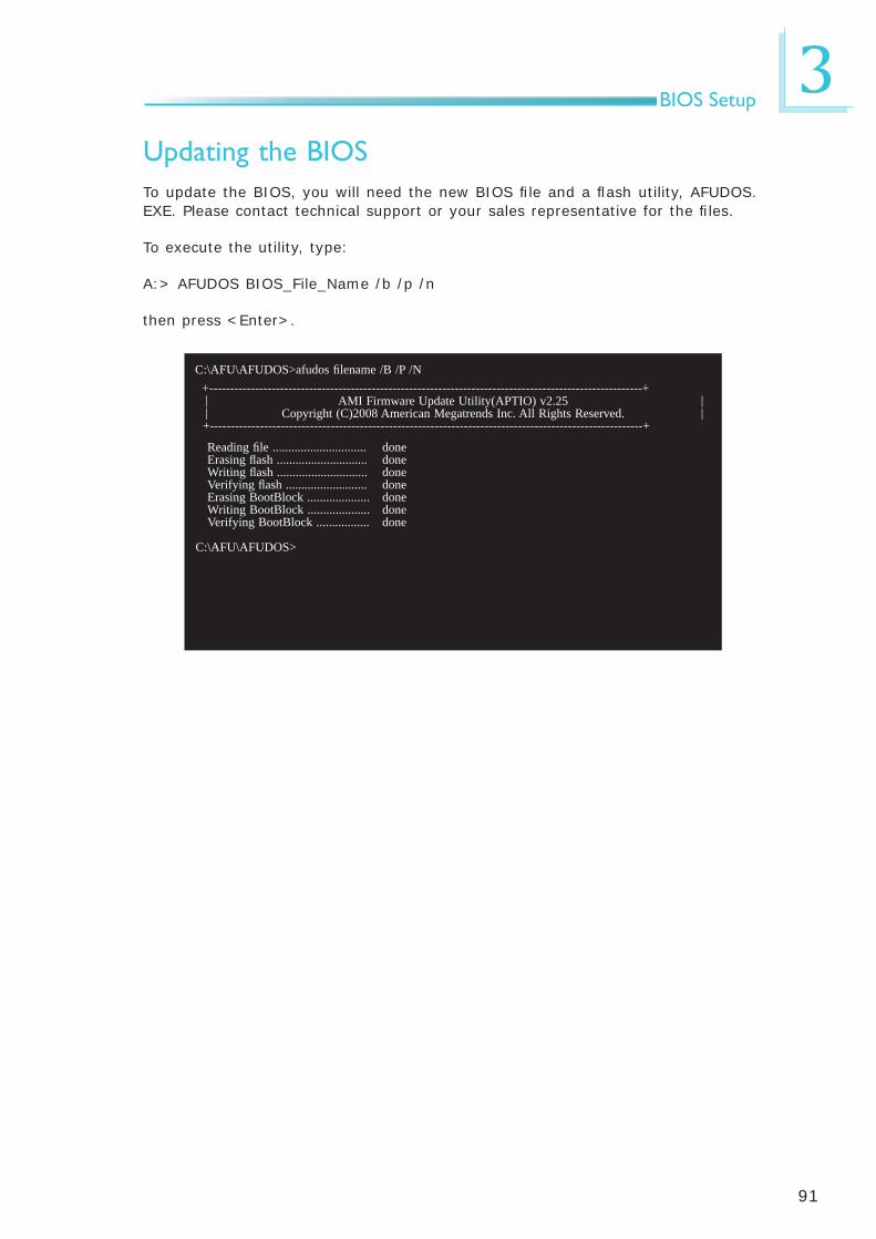
91
3BIOS Setup
Updating the BIOSTo update the BIOS, you will need the new BIOS fi le and a fl ash utility, AFUDOS.EXE. Please contact technical support or your sales representative for the fi les.
To execute the utility, type:
A:> AFUDOS BIOS_File_Name /b /p /n
then press <Enter>.
C:\AFU\AFUDOS>afudos fi lename /B /P /N +--------------------------------------------------------------------------------------------------------+
AMI Firmware Update Utility(APTIO) v2.25Copyright (C)2008 American Megatrends Inc. All Rights Reserved.
+--------------------------------------------------------------------------------------------------------+
||
||
Reading fi le .............................. Erasing fl ash ............................. Writing fl ash ............................. Verifying fl ash .......................... Erasing BootBlock .................... Writing BootBlock .................... Verifying BootBlock .................
C:\AFU\AFUDOS>
donedonedonedonedonedonedone

92
4Supported Software
The CD that came with the system board contains drivers, utilities and software applications required to enhance the performance of the system board.
Insert the CD into a CD-ROM drive. The autorun screen (Mainboard Utility CD) will appear. If after inserting the CD, “Autorun” did not automatically start (which is, the Mainboard Utility CD screen did not appear), please go directly to the root directory of the CD and double-click “Setup”.
Chapter 4 - Supported Software

93
4Supported Software
Auto Run Pages (for Windows 7)

94
4Supported Software
Microsoft .NET Framework 3.5 (for Windows XP only)
Note:Before installing Microsoft .NET Framework 3.5, make sure you have up-dated your Windows XP operating system to Service Pack 3.
To install the driver, click “Microsoft .NET Framework 3.5” on the main menu.
1. Read the license agreement carefully.
Click “I have read and accept the terms of the License Agreement” then click Install.
2. Setup is now installing the driver.

95
4Supported Software
3. Click Exit.
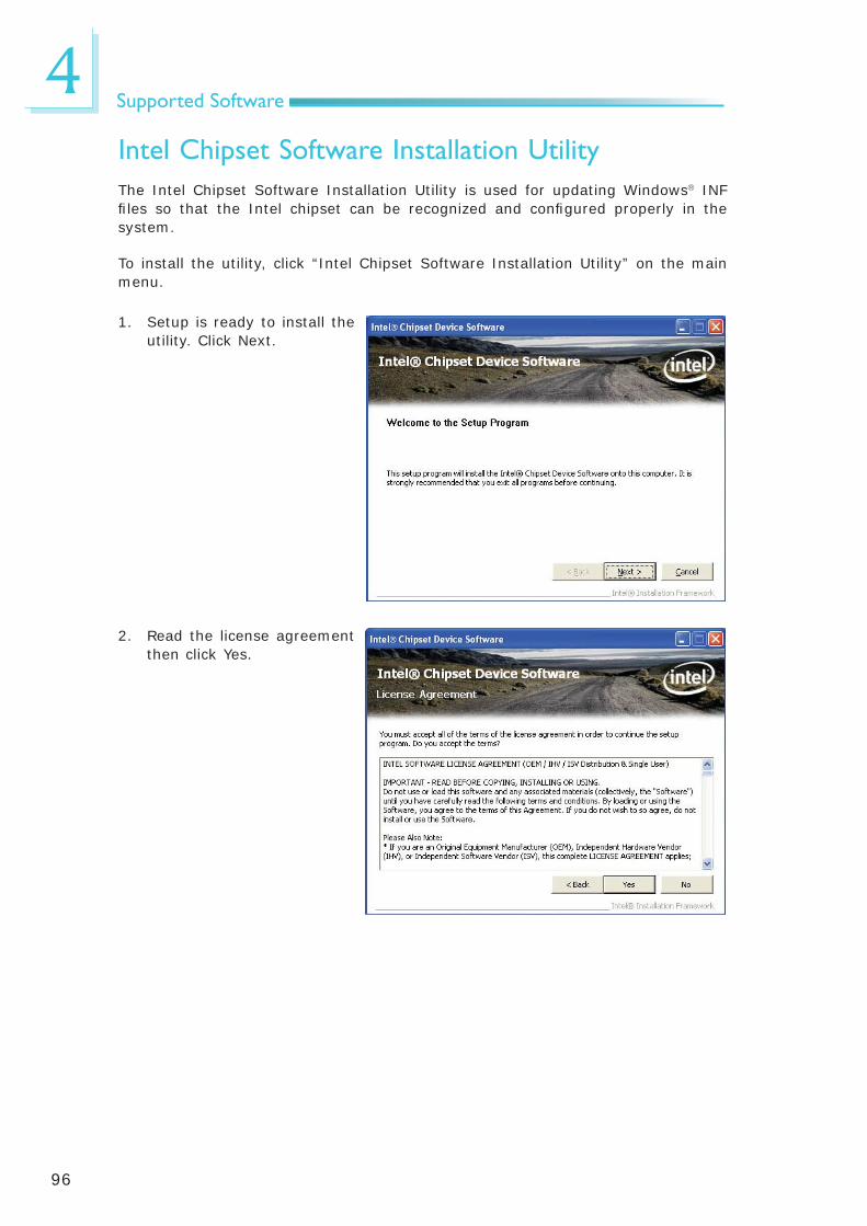
96
4Supported Software
Intel Chipset Software Installation UtilityThe Intel Chipset Software Installation Utility is used for updating Windows INF fi les so that the Intel chipset can be recognized and confi gured properly in the system.
To install the utility, click “Intel Chipset Software Installation Utility” on the main menu.
1. Setup is ready to install the utility. Click Next.
2. Read the license agreement then click Yes.

97
4Supported Software
3. Go through the readme document for more installa-tion tips then click Next.
4. Click Finish to exit setup.

98
4Supported Software
Intel Graphics Drivers (for Windows 7)To install the driver, click “Intel Graphics Drivers” on the main menu.
1. Setup is now ready to in-stall the graphics driver. Click Next.
By default, the “Automatically run WinSAT and enable the Windows Aero desktop theme” is enabled. With this enabled, after installing the graphics driver and the system rebooted, the screen will turn blank for 1 to 2 minutes (while WinSAT is running) before the Windows Vista desktop appears. The “blank screen” period is the time Windows is testing the graphics perfor-mance.
2. Read the license agreement then click Yes.

99
4Supported Software
4. Setup is now installing the driver. Click Next to con-tinue.
3. Go through the readme document for system re-quirements and installation tips then click Next.
5. Click “Yes, I want to restart this computer now” then click Finish.
Restarting the system will allow the new software in-stallation to take effect.

100
4Supported Software
Intel Graphics Drivers (for Windows XP)To install the driver, click “Intel Graphics Drivers” on the main menu.
3. Go through the readme document for more installa-tion tips then click Next.
1. Setup is ready to install the graphics driver. Click Next.
2. Read the license agreement then click Yes.

101
4Supported Software
4. Setup is currently installing the driver. After installation has completed, click Next.
5. Click “Yes, I want to restart this computer now.” then click Finish.
Restarting the system will allow the new software in-stalllation to take effect.

102
4Supported Software
Intel Management Engine DriversTo install the driver, click “Intel Management Engine Driver” on the main menu.
1. Setup is ready to install the driver. Click Next.
2. Read the license agreement then click Yes.
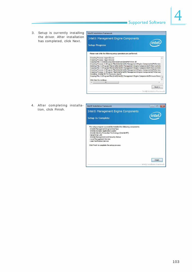
103
4Supported Software
3. Setup is currently installing the driver. After installation has completed, click Next.
4. After completing installa-tion, click Finish.

104
4Supported Software
Intel Rapid Storage DriversTo install the driver, click “Intel Rapid Storage Drivers” on the main menu.
1. Setup is ready to install the driver. Click Next.
2. Read the license agreement then click Yes.
Note:Windows Vista is not supported.

105
4Supported Software
4. Setup is currently installing the driver. After installation has completed, click Next.
5. Click “Yes, I want to restart this computer now.” then click Finish.
Restarting the system will allow the new software in-stalllation to take effect.
3. Go through the readme document for more installa-tion tips then click Next.

106
4Supported Software
Intel Turbo Boost Monitor (for Windows 7)
To install the driver, click “Intel Turbo Boost” on the main menu.
2. Read the license agreement and then click “I accept the terms in the license agree-ment”. Click Next.
3. The setup program is cur-rently installing the soft-ware.
1. Setup is now ready to in-stall the utility. Click Next.

107
4Supported Software
4. Click Finish.

108
4Supported Software
Intel LAN DriversTo install the driver, click “Intel LAN Drivers” on the main menu.
1. Setup is ready to install the driver. Click Next.
2. Click “I accept the terms in the license agreement” then click “Next”.
3. Select the program featuers you want installed then click Next.
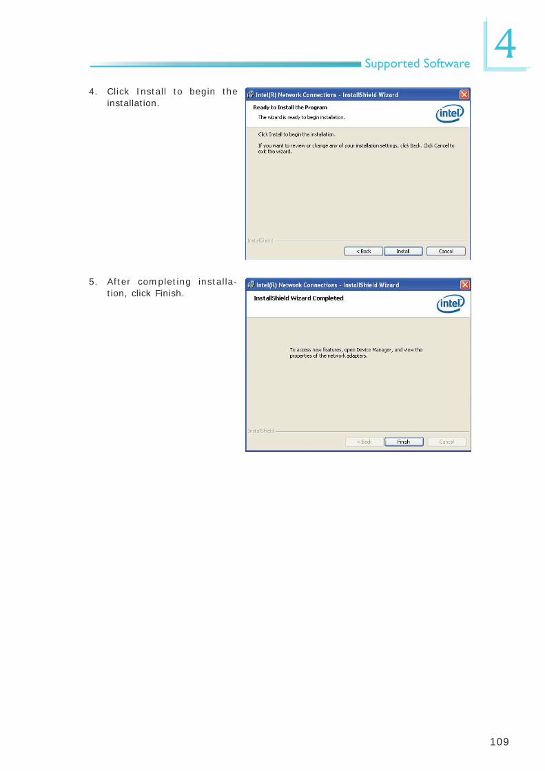
109
4Supported Software
4. Click Install to begin the installation.
5. After completing installa-tion, click Finish.

110
4Supported Software
Audio DriversTo install the driver, click “Audio Drivers” on the main menu.
2. Click “Yes, I want to restart my computer now” then click Finish.
Restarting the system will allow the new software in-stallation to take effect.
1. Setup is ready to install the driver. Click Next.
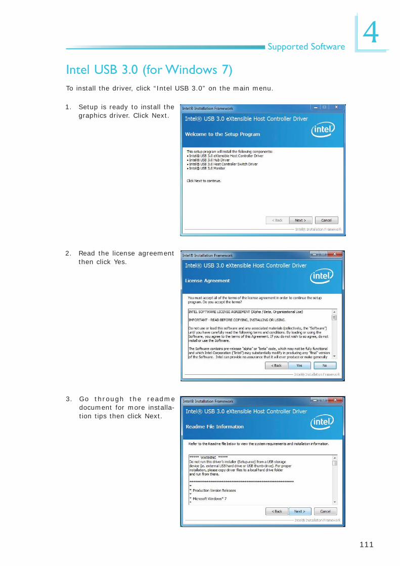
111
4Supported Software
Intel USB 3.0 (for Windows 7)To install the driver, click “Intel USB 3.0” on the main menu.
3. Go through the readme document for more installa-tion tips then click Next.
1. Setup is ready to install the graphics driver. Click Next.
2. Read the license agreement then click Yes.
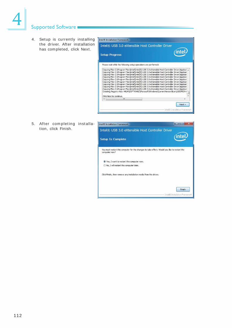
112
4Supported Software
4. Setup is currently installing the driver. After installation has completed, click Next.
5. After completing installa-tion, click Finish.

113
4Supported Software
Infineon TPM Driver and Tool (optional)To install the driver, click “Infi neon TPM driver and tool (option)” on the main menu.
1. TPM requires installing the Microsoft Visual C++ pack-age prior to installing the driver. Click Install.
2. The setup program is pre-paring to install the driver.
3. The setup program is ready to install the driver. Click Next.

114
4Supported Software
4. Click “I accept the terms in the license agreement” and then click “Next”.
5. Enter the necessary infor-mation and then click Next.
6. Select a setup type and then click Next.

115
4Supported Software
7. Click Install.
8. The setup program is cur-rently installing the driver.
9. Click Finish.

116
4Supported Software
10. Click Yes to restart the system.
Restarting the system will allow the new software installation to take effect.

117
4Supported Software
1. Setup is ready to instal the DFI Utility driver Click “Next”.
2. Click “I accept the terms in the license agreement” then click “Next”.
DFI UtilityDFI Utility provides information about the board, Watchdog, DIO, and Backlight. To access the utility, click “DFI Utility” on the main menu.
Note:If you are using Windows 7, you need to access the operating system as an administrator to be able to install the utility.

118
4Supported Software
4. Click “Install” to begin the installation.
5. After completing installa tion, click “Finish”.
3. Enter “User name” and “Organization” information then click “Next”.
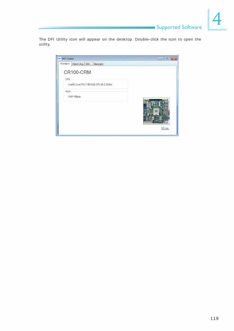
119
4Supported Software
The DFI Utility icon will appear on the desktop. Double-click the icon to open the utility.

120
4Supported Software
MyGuard Hardware MonitorTo install the driver, click “MyGuard Hardware Monitor” on the main menu.
1. Setup is ready to install the utility. Click Next.
2. Click Install to begin instal-lation.
3. Setup is currently installing the utility.
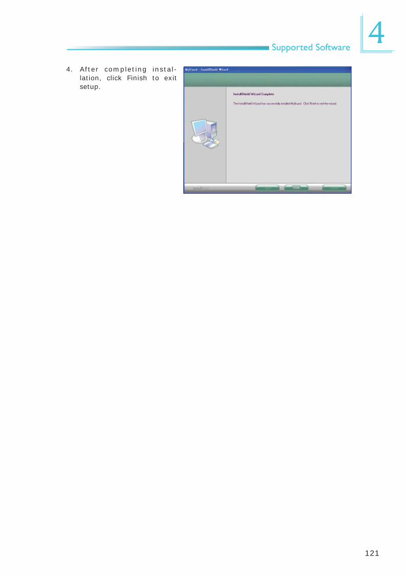
121
4Supported Software
4. After completing instal-lation, click Finish to exit setup.

122
4Supported Software
1. Click “I accept the agree-ment” then click Next.
Microsoft DirectX 9.0C (for Windows XP only)
To install the driver, click “Microsoft DirectX 9.0C” on the main menu.
2. To start installation, click Next.
3. Click Finish. Reboot the system for DirectX to take effect.

123
4Supported Software
F6 Floppy This is used to create a fl oppy driver diskette needed when you install Windows® XP using the F6 installation method. This will allow you to install the operating system onto a hard drive when in AHCI mode.
1. Insert a blank fl oppy diskette.
2. Locate for the drivers in the CD then copy them to the fl oppy diskette. The CD includes drivers for both 32-bit and 64-bit operating systems. The path to the drivers are shown below.
32-bit CD Drive:\AHCI_RAID\F6FLOPPY\f6fl py32
64-bit CD Drive:\AHCI_RAID\F6FLOPPY\f6fl py64

124
4Supported Software
Adobe Acrobat Reader 9.3To install the reader, click “Adobe Acrobat Reader 9.3” on the main menu.
1. Click Next to install or click Change Destination Folder to select another folder.
2. Click Install to begin instal-lation.
3. Click Finish to exit installa-tion.

125
5RAID
The system board allows confi guring RAID on Serial ATA drives. It supports RAID 0, RAID 1, RAID 5 and RAID 10.
RAID Levels
RAID 0 (Striped Disk Array without Fault Tolerance)
RAID 0 uses two new identical hard disk drives to read and write data in parallel, interleaved stacks. Data is divided into stripes and each stripe is written alter-nately between two disk drives. This improves the I/O performance of the drives at different channel; however it is not fault tolerant. A failed disk will result in data loss in the disk array.
RAID 1 (Mirroring Disk Array with Fault Tolerance)
RAID 1 copies and maintains an identical image of the data from one drive to the other drive. If a drive fails to function, the disk array management software directs all applications to the other drive since it contains a complete copy of the drive’s data. This enhances data protection and increases fault tolerance to the entire system. Use two new drives or an existing drive and a new drive but the size of the new drive must be the same or larger than the existing drive.
RAID 5
RAID 5 stripes data and parity information across hard drives. It is fault tolerant and provides better hard drive performance and more storage capacity.
RAID 10 (Mirroring and Striping)
RAID 10 is a combination of data striping and data mirroring providing the ben-efi ts of both RAID 0 and RAID 1. Use four new drives or an existing drive and three new drives for this confi guration.
Chapter 5 - RAID

126
5RAID
SettingsTo enable the RAID function, the following settings are required.
1. Connect the Serial ATA drives.
2. Confi gure Serial ATA in the AMI BIOS.
3. Confi gure RAID in the RAID BIOS.
4. Install the RAID driver during OS installation.
5. Install the Intel Rapid Storage Drivers.
Step 1: Connect the Serial ATA Drives
Refer to chapter 2 for details on connecting the Serial ATA drives.
Important:1. Make sure you have installed the Serial ATA drives and connected the
data cables otherwise you won’t be able to enter the RAID BIOS util-ity.
2. Treat the cables with extreme caution especially while creating RAID. A damaged cable will ruin the entire installation process and operat-ing system. The system will not boot and you will lost all data in the hard drives. Please give special attention to this warning because there is no way of recovering back the data.
Step 2: Configure Serial ATA in the AMI BIOS
1. Power-on the system then press <Del> to enter the main menu of the AMI BIOS.
2. Confi gure Serial ATA in the appropriate fi elds.
3. Save the changes in the Save & Exit menu.
4. Reboot the system.
Step 3: Configure RAID in the RAID BIOS
When the system powers-up and all drives have been detected, the Intel RAID BIOS status message screen will appear. Press the <Ctrl> and <I> keys simul-taneously to enter the utility. The utility allows you to build a RAID system on Serial ATA drives.

127
5RAID
Step 4: Install the RAID Driver During OS Installation
The RAID driver must be installed during the Windows® XP or Windows® 2000 in-stallation using the F6 installation method. This is required in order to install the operating system onto a hard drive or RAID volume when in RAID mode or onto a hard drive when in AHCI mode.
1. Start Windows Setup by booting from the installation CD.
2. Press <F6> when prompted in the status line with the ‘Press F6 if you need to install a third party SCSI or RAID driver’ message.
3. Press <S> to “Specify Additional Device”.
4. At this point you will be prompted to insert a fl oppy disk containing the RAID driver. Insert the RAID driver diskette.
5. Locate for the drive where you inserted the diskette then select RAID or AHCI controller that corresponds to your BIOS setup. Press <Enter> to confi rm.
You have successfully installed the driver. However you must continue installing the OS. Leave the fl oppy disk in the fl oppy drive until the system reboots itself because Windows setup will need to copy the fi les again from the fl oppy disk to the Windows installation folders. After Windows setup has copied these fi les again, remove the fl oppy diskette so that Windows setup can reboot as needed.

128
5RAID
4. Read the warning carefully then click Next.
Step 5: Install the Intel Rapid Storage Technology Utility
The Intel Rapid Storage Technology Utility can be installed from within Windows. It allows RAID volume management (create, delete, migrate) from within the operating system. It will also display useful SATA device and RAID volume in-formation. The user interface, tray icon service and monitor service allow you to monitor the current status of the RAID volume and/or SATA drives. It enables enhanced performance and power management for the storage subsystem.
1. Insert the provided CD into an optical drive.
2. Click “Intel Rapid Storage Technology Utility” on the main menu.
3. Setup is ready to install the utility. Click Next.

129
5RAID
5. Read the license agree-ment then click Yes.
6. Go through the readme document to view system requirements and installa-tion information then click Next.
7. Click “Yes, I want to restart my computer now” then click Finish.

130
6Intel AMT Settings
Chapter 6 - Intel AMT Settings
Overview Intel Active Management Technology (Intel® AMT) combines hardware and soft-ware solution to provide maximum system defense and protection to networked systems.
The hardware and software information are stored in non-volatile memory. With its built-in manageability and latest security applications, Intel® AMT provides the following functions.
• Discover
Allows remote access and management of networked systems even while PCs are powered off; signifi cantly reducing desk-side visits.
• Repair
Remotely repair systems after OS failures. Alerting and event logging help detect problems quickly to reduce downtime.
• Protect
Intel AMT’s System Defense capability remotely updates all systems with the latest security software. It protects the network from threats at the source by proactively blocking incoming threats, reactively containing infected clients before they impact the network, and proactively alerting when critical soft-ware agents are removed.

131
6Intel AMT Settings
Enable Intel® AMT in the AMI BIOS 1. Power-on the system then press <Del> to enter the main menu of the AMI
BIOS.
2. In the Advanced menu, select Enabled in the Intel AMT fi eld.
3. In the Advanced menu, select PCH-FW Confi guration.
Aptio Setup Utility - Copyright (C) 2011 American Megatrends, Inc.
Version 2.14.1219. Copyright (C) 2011 American Megatrends, Inc.
ME FW Version ME Firmware Mode ME Firmware Type ME Firmware SKU Firmware Update Confi guration
Advanced
8.0.2.1410Normal ModeFull Sku Firmware5MB
Select Screen Select ItemEnter: Select+/-: Change Opt.F1: General HelpF2: Previous ValuesF3: Optimized DefaultsF4: Save & Exit ESC: Exit
ACPI Power Management Confi guration
Aptio Setup Utility - Copyright (C) 2011 American Megatrends, Inc.
Version 2.14.1219. Copyright (C) 2011 American Megatrends, Inc.
ACPI Power Management Confi gurationTrusted ComputingPC Health StatusCPU Confi gurationSATA Confi gurationIntel TXT(LT) Confi gurationPCH-FW Confi gurationIntel(R) Anti-Theft Technology Confi gurationAMT Confi gurationUSB Confi gurationF81217 Second Super IO Confi gurationF71879 Super Super IO Confi gurationSerial Port Console RedirectionCPU PPM Confi guration
Save & ExitChipset Boot SecurityMain Advanced
Select Screen Select ItemEnter: Select+/-: Change Opt.F1: General HelpF2: Previous ValuesF3: Optimized DefaultsF4: Save & Exit ESC: Exit

132
6Intel AMT Settings
4. In the Save & Exit menu, select Save Changes and Reset then select OK.
Reset the system after saving the changes.
Aptio Setup Utility - Copyright (C) 2011 American Megatrends, Inc.
Version 2.14.1219. Copyright (C) 2011 American Megatrends, Inc.
Save Changes and ResetDiscard Changes and Reset
Restore DefaultsSave as User DefaultsRestore User Defaults
Boot OverrideSATA SM: ATAPI iHAS324 YSATA PM: WDC WD6402AAEX-00Z3A
Launch EFI Shell from fi lesystem device
ChipsetAdvancedMain Boot Security Save & Exit
Select Screen Select ItemEnter: Select+/-: Change Opt.F1: General HelpF2: Previous ValuesF3: Optimized DefaultsF4: Save & Exit ESC: Exit
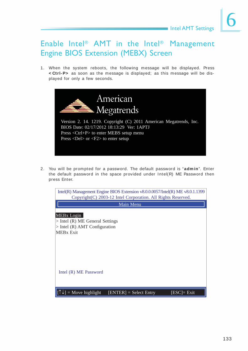
133
6Intel AMT Settings
Enable Intel® AMT in the Intel® Management Engine BIOS Extension (MEBX) Screen
1. When the system reboots, the following message will be displayed. Press <Ctrl-P> as soon as the message is displayed; as this message will be dis-played for only a few seconds.
2. You will be prompted for a password. The default password is “admin”. Enter the default password in the space provided under Intel(R) ME Password then press Enter.
Intel(R) Management Engine BIOS Extension v8.0.0.0057/Intel(R) ME v8.0.1.1399Copyright(C) 2003-12 Intel Corporation. All Rights Reserved.
Main Menu
MEBx Login> Intel (R) ME General Settings> Intel (R) AMT Confi gurationMEBx Exit
Intel (R) ME Password
[] = Move highlight [ENTER] = Select Entry [ESC]= Exit
Version 2. 14. 1219. Copyright (C) 2011 American Megatrends, Inc. BIOS Date: 02/17/2012 18:13:29 Ver: 1APTJPress <Ctrl+P> to enter MEBS setup menuPress <Del> or <F2> to enter setup
American Megatrends

134
6Intel AMT Settings
3. Enter a new password in the space provided under Intel(R) ME New Password then press Enter. The password must include:
• 8-32 characters • Strong 7-bit ASCII characters excluding : , and ” characters• At least one digit character (0, 1, ...9)• At least one 7-bit ASCII non alpha-numeric character, above 0x20, (e.g. !,
$, ;)• Both lower case and upper case characters
Intel(R) Management Engine BIOS Extension v8.0.0.0057/Intel(R) ME v8.0.1.1399Copyright(C) 2003-12 Intel Corporation. All Rights Reserved.
Main Menu
MEBx Login> Intel (R) ME General Settings> Intel (R) AMT Confi gurationMEBx Exit
Intel (R) ME Password
Intel (R) ME Password
[] = Move highlight [ENTER] = Select Entry [ESC]= Exit

135
6Intel AMT Settings
4. You will be asked to verify the password. Enter the same new password in the space provided under Verify Password then press Enter.
5. Select Intel(R) ME General Settings then press Enter.
Intel(R) Management Engine BIOS Extension v8.0.0.0057/Intel(R) ME v8.0.1.1399Copyright(C) 2003-12 Intel Corporation. All Rights Reserved.
Main Menu
MEBx Login> Intel (R) ME General Settings> Intel (R) AMT Confi gurationMEBx Exit
Intel (R) ME Password
[] = Move highlight [ENTER] = Select Entry [ESC]= Exit
Verify Password
Intel(R) Management Engine BIOS Extension v8.0.0.0057/Intel(R) ME v8.0.1.1399Copyright(C) 2003-12 Intel Corporation. All Rights Reserved.
Main Menu
> Intel (R) ME General Settings> Intel (R) AMT Confi gurationMEBx Exit
[] = Move highlight [ENTER] = Select Entry [ESC]= Exit

136
6Intel AMT Settings
6. Select Change Intel(R) ME Password then press Enter.
You will be prompted for a password. The default password is “admin”. Enter the default password in the space provided under Intel(R) ME New Password then press Enter.
• 8-32 characters • Strong 7-bit ASCII characters excluding : , and ” characters• At least one digit character (0, 1, ...9)• At least one 7-bit ASCII non alpha-numeric character, above 0x20, (e.g. !,
$, ;)• Both lower case and upper case characters
Intel(R) Management Engine BIOS Extension v8.0.0.0057/Intel(R) ME v8.0.1.1399Copyright(C) 2003-12 Intel Corporation. All Rights Reserved.
INTEL (R) ME PLATFORM CONFIGURATION
> Change ME Password Local FW Updtate <Enabled>> Power Control
Intel (R) ME New Password
[] = Move highlight [ENTER] = Select Entry [ESC]= Exit

137
6Intel AMT Settings
7. Select Local FW Update then press Enter. Select Enabled then press En-ter.
Intel(R) Management Engine BIOS Extension v8.0.0.0057/Intel(R) ME v8.0.1.1399Copyright(C) 2003-12 Intel Corporation. All Rights Reserved.
INTEL (R) ME PLATFORM CONFIGURATION
> Change ME Password Local FW Updtate <Enabled>> Power Control
<ENTER> = Complete Entry [ESC]= Discard Changes
DisabledEnabledPassword Protected
8. In the Intel(R) ME Platform Confi guration menu, select Power Control then press Enter.
Intel(R) Management Engine BIOS Extension v8.0.0.0057/Intel(R) ME v8.0.1.1399Copyright(C) 2003-12 Intel Corporation. All Rights Reserved.
INTEL (R) ME PLATFORM CONFIGURATION
> Change ME Password Local FW Updtate <Enabled>> Power Control
Intel (R) ME New Password
[] = Move highlight [ENTER] = Select Entry [ESC]= Exit

138
6Intel AMT Settings
9. In the Intel(R) ME Power Control menu, select Intel(R) ME ON in Host Sleep States then press Enter. Select an option then press Enter.
Intel(R) Management Engine BIOS Extension v8.0.0.0057/Intel(R) ME v8.0.1.1399Copyright(C) 2003-12 Intel Corporation. All Rights Reserved.
INTEL (R) ME POWER CONTROL
Intel (R) ME ON in Host Sleep States <Mobile ON in S0> Idle Timeout 65535
<ENTER> = Complete Entry [ESC]= Discard Changes
Mobile: ON in S0Mobile: ON in S0, ME Wake in S3, S4-5 (AC only)
10. In the Intel(R) ME Power Control menu, select Idle Timeout then press Enter. Enter the timeout value.
Intel(R) Management Engine BIOS Extension v8.0.0.0057/Intel(R) ME v8.0.1.1399Copyright(C) 2003-12 Intel Corporation. All Rights Reserved.
INTEL (R) ME POWER CONTROL
Intel (R) ME ON in Host Sleep States <Mobile ON in S0> Idle Timeout 65535
Timeout Value (1-65535)65535_
<ENTER> = Complete Entry [ESC]= Discard Changes

139
6Intel AMT Settings
11. Select Previous Menu until you return to the Main Menu. Select Intel(R) AMT Confi guration then press Enter.
12. In the Intel(R) AMT Confi guration menu, select Manageability Feature Selection then press Enter. Select disabled then press Enter.
Intel(R) Management Engine BIOS Extension v8.0.0.0057/Intel(R) ME v8.0.1.1399Copyright(C) 2003-12 Intel Corporation. All Rights Reserved.
INTEL (R) AMT CONFIGURATION
Manageability Feature Selection < Enabled> > SOL/ IDER/ KVM > User Consent Password Policy <Anytime>> Network Setup Activate Netwok Access Unconfi gure Network Access <Full Unprovision>> Remote Setup And Confi guration
[] = Move highlight [ENTER] = Select Entry [ESC]= Exit
Intel(R) Management Engine BIOS Extension v8.0.0.0057/Intel(R) ME v8.0.1.1399Copyright(C) 2003-12 Intel Corporation. All Rights Reserved.
INTEL (R) AMT CONFIGURATION
Manageability Feature Selection < Enabled> > SOL/ IDER/ KVM > User Consent Password Policy <Anytime>> Network Setup Activate Netwok Access Unconfi gure Network Access <Full Unprovision>> Remote Setup And Confi guration
DisabledEnabled
<ENTER> = Complete Entry [ESC]= Discard Changes

140
6Intel AMT Settings
13. In the Intel(R) AMT Confi guration menu, select SOL/IDER/KVM then press Enter.
Intel(R) Management Engine BIOS Extension v8.0.0.0057/Intel(R) ME v8.0.1.1399Copyright(C) 2003-12 Intel Corporation. All Rights Reserved.
SOL/ IDER/ KVM
Username and password < Enabled> SOL <Enabled> IDER <Enabled> KVM Feature Selection <Enabled> Legacy Redirection Mode <Disabled>
Menu for FW Redirection Confi guration
[] = Move highlight [ENTER] = Select Entry [ESC]= Exit
14. In the SOL/IDER/KVM menu, select Username and Password then press Enter. Select disabled then press Enter.
Intel(R) Management Engine BIOS Extension v8.0.0.0057/Intel(R) ME v8.0.1.1399Copyright(C) 2003-12 Intel Corporation. All Rights Reserved.
SOL/ IDER/ KVM
Username and password < Enabled> SOL <Enabled> IDER <Enabled> KVM Feature Selection <Enabled> Legacy Redirection Mode <Disabled>
DisabledEnabled
<ENTER> = Complete Entry [ESC]= Discard Changes

141
6Intel AMT Settings
15. In the SOL/IDER/KVM menu, select SOL then press Enter. Select disabled then press Enter.
16. In the SOL/IDER/KVM menu, select IDER then press Enter. Select disa-bled then press Enter.
Intel(R) Management Engine BIOS Extension v8.0.0.0057/Intel(R) ME v8.0.1.1399Copyright(C) 2003-12 Intel Corporation. All Rights Reserved.
SOL/ IDER/ KVM
Username and password < Enabled> SOL <Enabled> IDER <Enabled> KVM Feature Selection <Enabled> Legacy Redirection Mode <Disabled>
DisabledEnabled
Intel(R) Management Engine BIOS Extension v8.0.0.0057/Intel(R) ME v8.0.1.1399Copyright(C) 2003-12 Intel Corporation. All Rights Reserved.
SOL/ IDER/ KVM
Username and password < Enabled> SOL <Enabled> IDER <Enabled> KVM Feature Selection <Enabled> Legacy Redirection Mode <Disabled>
DisabledEnabled
<ENTER> = Complete Entry [ESC]= Discard Changes
<ENTER> = Complete Entry [ESC]= Discard Changes
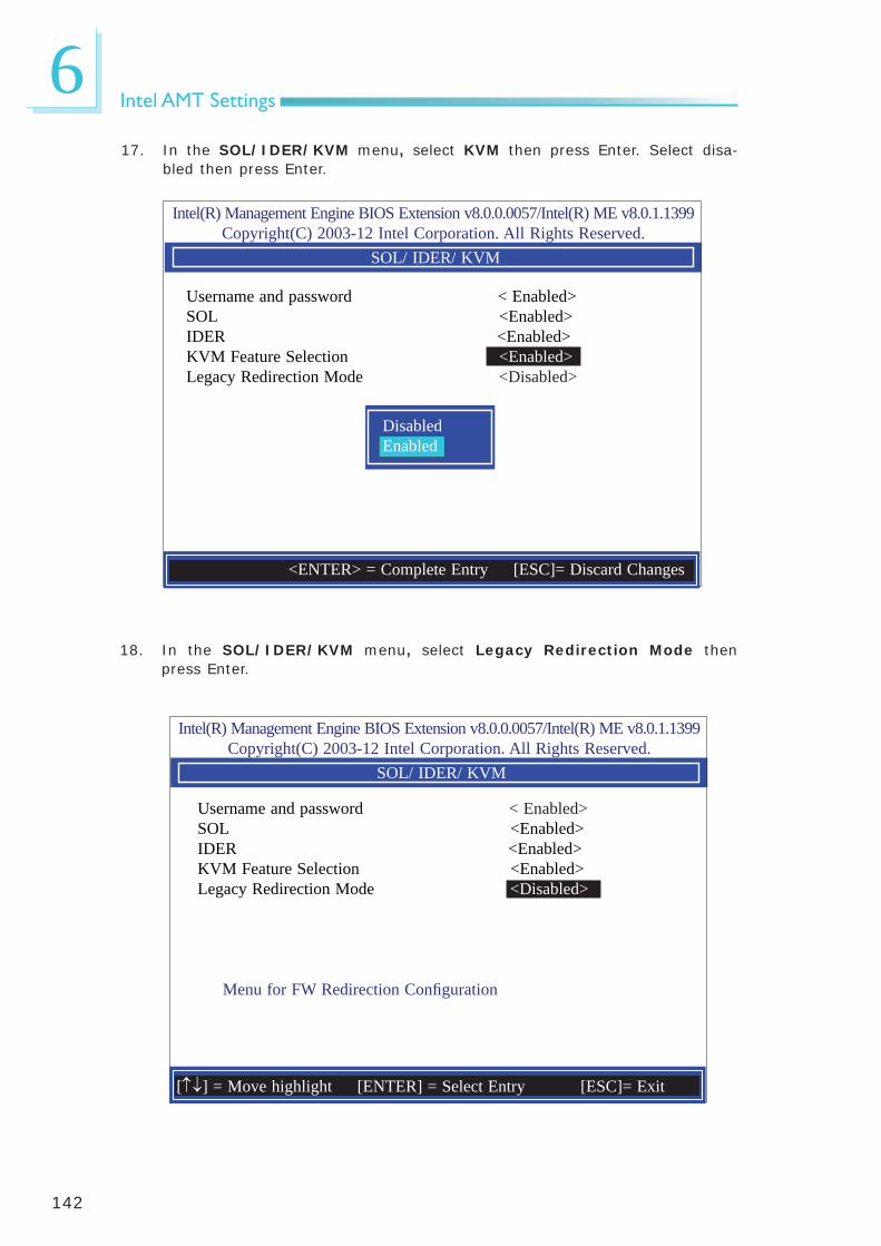
142
6Intel AMT Settings
18. In the SOL/IDER/KVM menu, select Legacy Redirection Mode then press Enter.
17. In the SOL/IDER/KVM menu, select KVM then press Enter. Select disa-bled then press Enter.
Intel(R) Management Engine BIOS Extension v8.0.0.0057/Intel(R) ME v8.0.1.1399Copyright(C) 2003-12 Intel Corporation. All Rights Reserved.
SOL/ IDER/ KVM
Username and password < Enabled> SOL <Enabled> IDER <Enabled> KVM Feature Selection <Enabled> Legacy Redirection Mode <Disabled>
DisabledEnabled
Intel(R) Management Engine BIOS Extension v8.0.0.0057/Intel(R) ME v8.0.1.1399Copyright(C) 2003-12 Intel Corporation. All Rights Reserved.
SOL/ IDER/ KVM
Username and password < Enabled> SOL <Enabled> IDER <Enabled> KVM Feature Selection <Enabled> Legacy Redirection Mode <Disabled>
Menu for FW Redirection Confi guration
[] = Move highlight [ENTER] = Select Entry [ESC]= Exit
<ENTER> = Complete Entry [ESC]= Discard Changes

143
6Intel AMT Settings
19. Select Enabled then press Enter.
20. Select Previous Menu until you return to the Intel(R) AMT Confi guration menu. Select User Consent then press Enter.
Intel(R) Management Engine BIOS Extension v8.0.0.0057/Intel(R) ME v8.0.1.1399Copyright(C) 2003-12 Intel Corporation. All Rights Reserved.
SOL/ IDER/ KVM
Username and password < Enabled> SOL <Enabled> IDER <Enabled> KVM Feature Selection <Enabled> Legacy Redirection Mode <Disabled>
DisabledEnabled
Intel(R) Management Engine BIOS Extension v8.0.0.0057/Intel(R) ME v8.0.1.1399Copyright(C) 2003-12 Intel Corporation. All Rights Reserved.
USER CONSENT
User Opt-in < KVM> Opt-in Confi guration from Remote IT < Enabled>
Confi gure when user consent should be required.
[] = Move highlight [ENTER] = Select Entry [ESC]= Exit
<ENTER> = Complete Entry [ESC]= Discard Changes

144
6Intel AMT Settings
21. In the User Consent Confi guration menu, select User Opt-in then press Enter. Select None then press Enter.
[ENTER] = Access
Intel(R) Management Engine BIOS Extension v8.0.0.0057/Intel(R) ME v8.0.1.1399Copyright(C) 2003-12 Intel Corporation. All Rights Reserved.
USER CONSENT
User Opt-in < KVM> Opt-in Confi guration from Remote IT < Enabled>
NONEKVMALL
22. In the User Consent Confi guration menu, select Opt-in Confi gurable from Remote IT then press Enter. Select Disable Remote Control of KVM Opt-in Policy then press Enter.
Intel(R) Management Engine BIOS Extension v8.0.0.0057/Intel(R) ME v8.0.1.1399Copyright(C) 2003-12 Intel Corporation. All Rights Reserved.
USER CONSENT
User Opt-in < KVM> Opt-in Confi guration from Remote IT < Enabled>
DisabledEnabled
<ENTER> = Complete Entry [ESC]= Discard Changes
<ENTER> = Complete Entry [ESC]= Discard Changes

145
6Intel AMT Settings
23. Select Previous Menu until you return to the Intel(R) AMT Confi guration menu. Select Password Policy then press Enter.
You may choose to use a password only during setup and confi guration or to use a password anytime the system is being accessed.
Intel(R) Management Engine BIOS Extension v8.0.0.0057/Intel(R) ME v8.0.1.1399Copyright(C) 2003-12 Intel Corporation. All Rights Reserved.
INTEL (R) AMT CONFIGURATION
Manageability Feature Selection < Enabled> > SOL/ IDER/ KVM > User Consent Password Policy <Anytime>> Network Setup Activate Netwok Access Unconfi gure Network Access <Full Unprovision>> Remote Setup And Confi guration
[ENTER] = Select Entry [ESC]= Exit
Default Password OnlyDuring Step And Confi gurationAnytime
24. In the Intel(R) AMT Confi guration menu, select Network Setup then press Enter.
Intel(R) Management Engine BIOS Extension v8.0.0.0057/Intel(R) ME v8.0.1.1399Copyright(C) 2003-12 Intel Corporation. All Rights Reserved.
INTEL (R) AMT CONFIGURATION
Manageability Feature Selection < Enabled> > SOL/ IDER/ KVM > User Consent Password Policy <Anytime>> Network Setup Activate Netwok Access Unconfi gure Network Access <Full Unprovision>> Remote Setup And Confi guration
[] = Move highlight [ENTER] = Select Entry [ESC]= Exit

146
6Intel AMT Settings
Intel(R) Management Engine BIOS Extension v8.0.0.0057/Intel(R) ME v8.0.1.1399Copyright(C) 2003-12 Intel Corporation. All Rights Reserved.
INTEL (R) ME NETWORK SETUP
> Intel (R) ME Network Name Settings > TCP/ IP Settings
[] = Move highlight [ENTER] = Select Entry [ESC]= Exit
25. In the Intel(R) Network Setup menu, select Intel(R) ME Network Name Settings then press Enter.
26. In the Intel(R) ME Network Name Settings menu, select Host Name then press Enter. Enter the computer’s host name then press Enter.
Intel(R) Management Engine BIOS Extension v8.0.0.0057/Intel(R) ME v8.0.1.1399Copyright(C) 2003-12 Intel Corporation. All Rights Reserved.
INTEL (R) ME NETWORK NAME SETTINGS
Host Name _ Domain Name _ Shared/ Dedicated FQDN <Shared> Dynamic DNS Update <Disabled>
Computer Host Name
<ENTER> = Complete Entry [ESC]= Discard Changes

147
6Intel AMT Settings
27. Select Domain Name then press Enter. Enter the computer’s domain name then press Enter.
28. Select Shared/Dedicated FQDN then press Enter. Select Shared or Dedi-cated then press Enter.
Intel(R) Management Engine BIOS Extension v8.0.0.0057/Intel(R) ME v8.0.1.1399Copyright(C) 2003-12 Intel Corporation. All Rights Reserved.
INTEL (R) ME NETWORK NAME SETTINGS
Host Name _ Domain Name _ Shared/ Dedicated FQDN <Shared> Dynamic DNS Update <Disabled>
Computer Domain Name
Intel(R) Management Engine BIOS Extension v8.0.0.0057/Intel(R) ME v8.0.1.1399Copyright(C) 2003-12 Intel Corporation. All Rights Reserved.
INTEL (R) ME NETWORK NAME SETTINGS
Host Name _ Domain Name _ Shared/ Dedicated FQDN <Shared> Dynamic DNS Update <Disabled>
Dedicatedshared
<ENTER> = Complete Entry [ESC]= Discard Changes
<ENTER> = Complete Entry [ESC]= Discard Changes

148
6Intel AMT Settings
29. Select Dynamic DNS Update then press Enter. Select Enabled or Disabled then press Enter.
Intel(R) Management Engine BIOS Extension v8.0.0.0057/Intel(R) ME v8.0.1.1399Copyright(C) 2003-12 Intel Corporation. All Rights Reserved.
INTEL (R) ME NETWORK NAME SETTINGS Host Name _ Domain Name _ Shared/ Dedicated FQDN <Shared> Dynamic DNS Update <Disabled>
DisabledEnabled
30. Select Previous Menu until you return to the Intel(R) ME Network Setup menu. Select TCP/IP Settings then press Enter.
Intel(R) Management Engine BIOS Extension v8.0.0.0057/Intel(R) ME v8.0.1.1399Copyright(C) 2003-12 Intel Corporation. All Rights Reserved.
TCP/ IP SETTINGS
> Wired LAN IPV4 Confi guration
[] = Move highlight [ENTER] = Select Entry [ESC]= Exit
<ENTER> = Complete Entry [ESC]= Discard Changes

149
6Intel AMT Settings
31. In the TCP/IP Settings menu, select Wired LAN IPV4 Confi guration then press Enter.
Intel(R) Management Engine BIOS Extension v8.0.0.0057/Intel(R) ME v8.0.1.1399Copyright(C) 2003-12 Intel Corporation. All Rights Reserved.
WIRED LAN IPV4 CONFIGURATION
DHCP Mode <Enabled>
DisabledEnabled
32. Select Previous Menu until you return to the Intel(R) AMT Confi guration menu. Select Activate Network Access then press Enter. Type Y then press Enter.
Intel(R) Management Engine BIOS Extension v8.0.0.0057/Intel(R) ME v8.0.1.1399Copyright(C) 2003-12 Intel Corporation. All Rights Reserved.
INTEL (R) AMT CONFIGURATION
Manageability Feature Selection < Enabled> > SOL/ IDER/ KVM > User Consent Password Policy <Anytime>> Network Setup Activate Netwok Access Unconfi gure Network Access <Full Unprovision>> Remote Setup And Confi guration
[] = Move highlight [ENTER] = Select Entry [ESC]= Exit
Activiates the current network settings and opens the ME netwotk interface
Continue: (Y/N)
<ENTER> = Complete Entry [ESC]= Discard Changes

150
6Intel AMT Settings
33. In the Intel(R) AMT Confi guration menu, select Unconfi gure Network Access then press Enter. Type Y then press Enter.
Intel(R) Management Engine BIOS Extension v8.0.0.0057/Intel(R) ME v8.0.1.1399Copyright(C) 2003-12 Intel Corporation. All Rights Reserved.
INTEL (R) AMT CONFIGURATION
Manageability Feature Selection < Enabled> > SOL/ IDER/ KVM > User Consent Password Policy <Anytime>> Network Setup Activate Netwok Access Unconfi gure Network Access <Full Unprovision>> Remote Setup And Confi guration
Full Unprovision
34. In the Intel(R) AMT Confi guration menu, select Remote Setup And Confi guration then press Enter.
Intel(R) Management Engine BIOS Extension v8.0.0.0057/Intel(R) ME v8.0.1.1399Copyright(C) 2003-12 Intel Corporation. All Rights Reserved.
INTEL (R) AMT CONFIGURATION
Manageability Feature Selection < Enabled> > SOL/ IDER/ KVM > User Consent Password Policy <Anytime>> Network Setup Activate Netwok Access Unconfi gure Network Access <Full Unprovision>> Remote Setup And Confi guration
[] = Move highlight [ENTER] = Select Entry [ESC]= Exit
<ENTER> = Complete Entry [ESC]= Discard Changes

151
6Intel AMT Settings
[ESC] = Exit
35. In the Intel(R) Automated Setup And Confi guration menu, select Cur-rent Provisioning Mode then press Enter.
36. In the Intel(R) Automated Setup And Confi guration menu, select Pro-visioning Record then press Enter.
Intel(R) Management Engine BIOS Extension v8.0.0.0057/Intel(R) ME v8.0.1.1399Copyright(C) 2003-12 Intel Corporation. All Rights Reserved.INTEL (R) AUTOMATED SETUP AND CONFIGURATION
Current Provisioning Mode Provisioning Record Provisioning Server IPV4/IPV6 _ Provisioning Server FQDN _> RCFG> TLS PSK> TLS PKI
[] = Move highlight [ENTER] = Select Entry [ESC]= Exit
Provisioning Mode:PKI
Intel(R) Management Engine BIOS Extension v8.0.0.0057/Intel(R) ME v8.0.1.1399Copyright(C) 2003-12 Intel Corporation. All Rights Reserved.INTEL (R) AUTOMATED SETUP AND CONFIGURATION
Current Provisioning Mode Provisioning Record Provisioning Server IPV4/IPV6 _ Provisioning Server FQDN _> RCFG> TLS PSK> TLS PKI
[] = Move highlight [ENTER] = Select Entry [ESC]= Exit
Provision Record is not present

152
6Intel AMT Settings
37. Select Previous Menu until you return to the Intel(R) Automated Setup And Confi guration menu. Select Provisioning Server IPV4/IPV6 then press Enter. Type server address then press Enter.
Intel(R) Management Engine BIOS Extension v8.0.0.0057/Intel(R) ME v8.0.1.1399Copyright(C) 2003-12 Intel Corporation. All Rights Reserved.INTEL (R) AUTOMATED SETUP AND CONFIGURATION
Current Provisioning Mode Provisioning Record Provisioning Server IPV4/IPV6 _ Provisioning Server FQDN _> RCFG> TLS PSK> TLS PKI Provisioning server address
38. In the Intel(R) Automated Setup And Confi guration menu, select Provisioning Server FQDN then press Enter. Type FQDN of provisioning server then press Enter.
Intel(R) Management Engine BIOS Extension v8.0.0.0057/Intel(R) ME v8.0.1.1399Copyright(C) 2003-12 Intel Corporation. All Rights Reserved.INTEL (R) AUTOMATED SETUP AND CONFIGURATION
Current Provisioning Mode Provisioning Record Provisioning Server IPV4/IPV6 _ Provisioning Server FQDN _> RCFG> TLS PSK> TLS PKI
Enter FQDN of provisioning server
<ENTER> = Complete Entry [ESC]= Discard Changes
<ENTER> = Complete Entry [ESC]= Discard Changes

153
6Intel AMT Settings
39. In the Intel(R) Remote Confi guration menu, select Start Confi guration then press Enter. Type Y then press Enter.
[ESC] = Exit
Intel(R) Management Engine BIOS Extension v8.0.0.0057/Intel(R) ME v8.0.1.1399Copyright(C) 2003-12 Intel Corporation. All Rights Reserved.
INTEL (R) REMOTE CONFIGURATION
Start Confi guration
[] = Move highlight [ENTER] = Select Entry [ESC]= Exit
This will activate Remote Confi guration.Continue: (Y/N)
40. In the Intel(R) Automated Setup And Confi guration menu, select TLS PSK then press Enter.
Intel(R) Management Engine BIOS Extension v8.0.0.0057/Intel(R) ME v8.0.1.1399Copyright(C) 2003-12 Intel Corporation. All Rights Reserved.
INTEL (R) TLS PSK CONFIGURATION
Set PID and PPS ** _Delete PID and PPS **
Enter PID (e.g. ABCD-1234)
<ENTER> = Complete Entry [ESC]= Exit

154
6Intel AMT Settings
Intel(R) Management Engine BIOS Extension v8.0.0.0057/Intel(R) ME v8.0.1.1399Copyright(C) 2003-12 Intel Corporation. All Rights Reserved.
INTEL (R) TLS PSK CONFIGURATION
Set PID and PPS ** _Delete PID and PPS **
<ENTER> = Complete Entry [ESC]= Exit
Enter PID (e.g. ABCD-1234)
41. In the Intel(R) Remote Confi guration menu, select Set PID and PPS ** then press Enter. Type PID code then press Enter.
Intel(R) Management Engine BIOS Extension v8.0.0.0057/Intel(R) ME v8.0.1.1399Copyright(C) 2003-12 Intel Corporation. All Rights Reserved.INTEL (R) AUTOMATED SETUP AND CONFIGURATION
[] = Move highlight [ENTER] = Select Entry [ESC]= Exit
CAUTION:This will delete the PID and PPS entries.
Continue: (Y/N)
Set PID and PPS ** Delete PID and PPS **
42. In the Intel(R) Remote Confi guration menu, select Delete PID and PPS ** then press Enter. Type Y then press Enter.

155
6Intel AMT Settings
43. Select Previous Menu until you return to the Intel(R) Automated Setup And Confi guration menu. Select TLS PKI then press Enter.
Intel(R) Management Engine BIOS Extension v8.0.0.0057/Intel(R) ME v8.0.1.1399Copyright(C) 2003-12 Intel Corporation. All Rights Reserved.INTEL (R) AUTOMATED SETUP AND CONFIGURATION
Current Provisioning Mode Provisioning Record Provisioning Server IPV4/IPV6 _ Provisioning Server FQDN _> RCFG> TLS PSK> TLS PKI
[] = Move highlight [ENTER] = Select Entry [ESC]= Exit
44. In the Intel(R) Remote Confi guration menu, select Remote Confi gura-tion ** then press Enter. Select Disabled then press Enter.
Intel(R) Management Engine BIOS Extension v8.0.0.0057/Intel(R) ME v8.0.1.1399Copyright(C) 2003-12 Intel Corporation. All Rights Reserved.
INTEL (R) REMOTE CONFIGURATION
Remote Confi guration ** <Enabled> PKI DNS Suffi x _> Manage Hashes
DisabledEnabled
<ENTER> = Complete Entry [ESC]= Discard Changes

156
6Intel AMT Settings
45. In the Intel(R) Remote Confi guration menu, select PKI DNS Suffi x then press Enter. Type PKI DNS Suffi x then press Enter.
Intel(R) Management Engine BIOS Extension v8.0.0.0057/Intel(R) ME v8.0.1.1399Copyright(C) 2003-12 Intel Corporation. All Rights Reserved.
INTEL (R) REMOTE CONFIGURATION
Remote Confi guration ** <Enabled> PKI DNS Suffi x _> Manage Hashes
Enter PKI DNS Suffi x
46. In the Intel(R) Remote Confi guration menu, select Manage Hashes then press Enter.
Intel(R) Management Engine BIOS Extension v8.0.0.0057/Intel(R) ME v8.0.1.1399Copyright(C) 2003-12 Intel Corporation. All Rights Reserved.
INTEL (R) REMOTE CONFIGURATIONHash Name Active Default Algorithm VeriSign Class 3 Active: [*] Default: [*] SHA1VeriSign Class 3 Active: [*] Default: [*] SHA1Go Daddy Class 2 Active: [*] Default: [*] SHA1Comodo AAA CA Active: [*] Default: [*] SHA1Starfi eld Class 2 Active: [*] Default: [*] SHA1VeriSign Class 3 Active: [*] Default: [*] SHA1VeriSign Class 3 Active: [*] Default: [*] SHA1VeriSign Class 3 Active: [*] Default: [*] SHA1GTE CyberTrust G1 Active: [*] Default: [*] SHA1Baltimore Cyber Tr Active: [*] Default: [*] SHA1Cyber Trust Global Active: [*] Default: [*] SHA1Verizon Global Ro Active: [*] Default: [*] SHA1Entrust. net CA (2 Active: [*] Default: [*] SHA1
[Ins]= Add New ash [Delete] = Delete Hash [+] = Activate Hash [] =Move highlight [ENTER] = View Hash [Esc]= Exit
<ENTER> = Complete Entry [ESC]= Discard Changes

157
6Intel AMT Settings
47. Select Previous Menu until you return to the Main Menu. Select Exit then press Enter. Type Y then press Enter.
Intel(R) Management Engine BIOS Extension v8.0.0.0057/Intel(R) ME v8.0.1.1399Copyright(C) 2003-12 Intel Corporation. All Rights Reserved.
Main Menu
> Intel (R) ME General Settings> Intel (R) AMT Confi gurationMEBx Exit
Exit
[] = Move highlight [ENTER] = Select Entry [ESC]= Exit
Are you sure you want to exit? (Y/N)

158
ANLITE and AHCI Installation Guide
Appendix A - NLITE and AHCI Installation Guide
nLitenLite is an application program that allows you to customize your XP installation disc by integrating the RAID/AHCI drivers into the disc. By using nLite, the F6 function key usually required during installation is no longer needed.
Note:The installation steps below are based on nLite version 1.4.9. Installa-tion procedures may slightly vary if you’re using another version of the program.
1. Download the program from nLite’s offi cal website.
http://www.nliteos.com/download.html
2. Install nLite.
Important:Due to it’s coding with Visual.Net, you may need to fi rst install .NET Framework prior to installing nLite.
3. Download relevant RAID/AHCI driver fi les from Intel’s website. The drivers you choose will depend on the operating system and chipset used by your computer.
The downloaded driver fi les should include iaahci.cat, iaAHCI.inf, iastor.cat, iaStor.inf, IaStor.sys, license.txt and TXTSETUP.OEM.

159
ANLITE and AHCI Installation Guide
4. Insert the XP installation disc into an optical drive.
5. Launch nLite. The Welcome screen will appear. Click Next.
6. Click Next to temporarily save the Windows installa-tion fi les to the designated default folder.
If you want to save them in another folder, click Browse, select the folder and then click Next.

160
ANLITE and AHCI Installation Guide
7. Click Next.
8. In the Task Selection dia-log box, click Drivers and Bootable ISO. Click Next.

161
ANLITE and AHCI Installation Guide
9. Click Insert and then se-lect Multiple driver folder to select the drivers you will integrate. Click Next.
10. Select only the drivers appropriate for the Win-dows version that you are using and then click OK.
Integrating 64-bit driv-ers into 32-bit Windows or vice versa will cause fi le load errors and failed installation.

162
ANLITE and AHCI Installation Guide
11. If you are uncertain of the southbridge chip used on your motherboard, select all RAID/AHCI con-trollers and then click OK.
12. Click Next.

163
ANLITE and AHCI Installation Guide
13. The program is currently integrating the drivers and applying changes to the installation.
14. When the program is fi n-ished applying the chang-es, click Next.

164
ANLITE and AHCI Installation Guide
15. To create an image, se-lect the Create Image mode under the General section and then click Next.
16. Or you can choose to burn it directly to a disc by selecting the Direct Burn mode under the General section.
Select the optical device and all other necessary settings and then click Next.

165
ANLITE and AHCI Installation Guide
17. You have finished cus-tomizing the Windows XP installation disc. Click Finish.
Enter the BIOS utility to confi gure the SATA con-troller to RAID/AHCI. You can now install Windows XP.

166
ANLITE and AHCI Installation Guide
AHCIThe installation steps below will guide you in confi guring your SATA drive to AHCI mode.
1. Enter the BIOS utility and confi gure the SATA controller to IDE mode.
2. Install Windows XP but do not press F6.
3. Download relevant RAID/AHCI driver fi les supported by the motherboard chipset from Intel’s website.
Transfer the downloaded driver fi les to C:\AHCI.
4. Open Device Manager and right click on one of the Intel Serial ATA Storage Controllers, then select Update Driver.
If the controller you se-lected did not work, try selecting another one.

167
ANLITE and AHCI Installation Guide
5. In the Hardware Update Wizard dialog box, select “No, not this time” then click Next.
6. Select “Install from a list or specifi c location (Ad-vanced)” and then click Next.
7. Select “Don’t search. I will choose the driver to install” and then click Next.
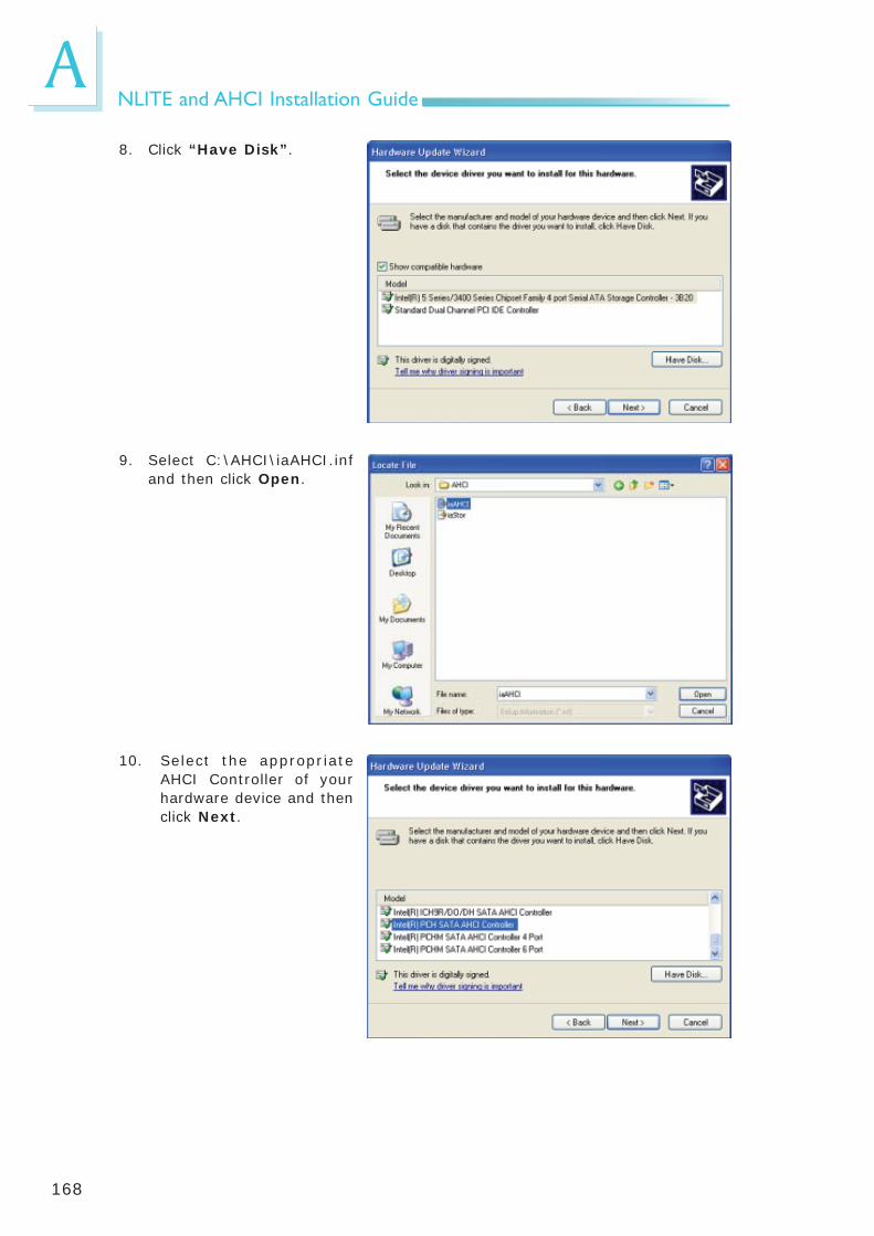
168
ANLITE and AHCI Installation Guide
8. Click “Have Disk”.
9. Select C:\AHCI\iaAHCI.inf and then click Open.
10. Select the appropriate AHCI Controller of your hardware device and then click Next.

169
ANLITE and AHCI Installation Guide
11. A warning message ap-peared because the se-lected SATA controller did not match your hardware device.
Ignore the warning and click Yes to proceed.
12. Click Finish.
13. The system’s settings have been changed. Win-dows XP requires that you restart the computer. Click Yes.
14. Enter the BIOS utility and modify the SATA control-ler from IDE to AHCI. By doing so, Windows will work normally with the SATA controller that is in AHCI mode.

170
AWatchdog Timer
Appendix B - Watchdog Sample Code
;Software programming example:
;---------------------------------------------;(1) Enter Super IO Confi guration mode;---------------------------------------------MOV DX,2EHMOV AL,87HOUT DX,ALOUT DX,AL
;-------------------------------------------------------------------------------------------;(2) Confi guration Logical Device 7, register CRF5/CRF6 (WDT Control /WDT timer);-------------------------------------------------------------------------------------------MOV DX,2EHMOV AL,07H ;Ready to Program Logical DeviceOUT DX,AL
MOV DX,2FHMOV AL,07H ;Select Logical Device 7OUT DX,AL
MOV DX,2EHMOV AL, F6H ;Select watchdog timer registerOUT DX,AL
MOV DX,2FHMOV AL,10H ;Set watchdog timer valueOUT DX,AL
MOV DX,2EHMOV AL, F5H ;Select watchdog Control RegisterOUT DX,AL
MOV DX,2FHMOV AL,61H ;Set Watchdog Control ValueOUT DX,AL
;----------------------------------------------------------------;(1) Exit extended function mode;----------------------------------------------------------------MOV DX,2EHMOV AL,AAHOUT DX,AL

C
171
System Error Message
When the BIOS encounters an error that requires the user to correct something, either a beep code will sound or a message will be displayed in a box in the mid-dle of the screen and the message, PRESS F1 TO CONTINUE, CTRL-ALT-ESC or DEL TO ENTER SETUP, will be shown in the information box at the bottom. Enter Setup to correct the error.
Error MessagesOne or more of the following messages may be displayed if the BIOS detects an error during the POST. This list indicates the error messages for all Awards BIO-Ses:
CMOS BATTERY HAS FAILED
The CMOS battery is no longer functional. It should be replaced.
ImportantDanger of explosion if battery incorrectly replaced. Replace only with the same or equivalent type recommended by the manufacturer. Dispose of used batteries according to the battery manufacturer’s instructions.
CMOS CHECKSUM ERROR
Checksum of CMOS is incorrect. This can indicate that CMOS has become cor-rupt. This error may have been caused by a weak battery. Check the battery and replace if necessary.
DISPLAY SWITCH IS SET INCORRECTLY
The display switch on the motherboard can be set to either monochrome or color. This indicates the switch is set to a different setting than indicated in Setup. Determine which setting is correct, either turn off the system and change the jumper or enter Setup and change the VIDEO selection.
FLOPPY DISK(S) fail (80)
Unable to reset fl oppy subsystem.
FLOPPY DISK(S) fail (40)
Floppy type mismatch.
Hard Disk(s) fail (80)
HDD reset failed.
Hard Disk(s) fail (40)
HDD controller diagnostics failed.
Appendix C - System Error Message

C
172
System Error Message
Hard Disk(s) fail (20)
HDD initialization error.
Hard Disk(s) fail (10)
Unable to recalibrate fi xed disk.
Hard Disk(s) fail (08)
Sector Verify failed.
Keyboard is locked out - Unlock the key
The BIOS detects that the keyboard is locked. Keyboard controller is pulled low.
Keyboard error or no keyboard present
Cannot initialize the keyboard. Make sure the keyboard is attached correctly and no keys are being pressed during the boot.
Manufacturing POST loop
System will repeat POST procedure infi nitely while the keyboard controller is pull low. This is also used for the M/B burn in test at the factory.
BIOS ROM checksum error - System halted
The checksum of ROM address F0000H-FFFFFH is bad.
Memory test fail
The BIOS reports memory test fail if the memory has error(s).

D
173
Troubleshooting
Troubleshooting ChecklistThis chapter of the manual is designed to help you with problems that you may encounter with your personal computer. To effi ciently troubleshoot your system, treat each problem individually. This is to ensure an accurate diagnosis of the problem in case a problem has multiple causes.
Some of the most common things to check when you encounter problems while using your system are listed below.
1. The power switch of each peripheral device is turned on.
2. All cables and power cords are tightly connected.
3. The electrical outlet to which your peripheral devices are connected is work-ing. Test the outlet by plugging in a lamp or other electrical device.
4. The monitor is turned on.
5. The display’s brightness and contrast controls are adjusted properly.
6. All add-in boards in the expansion slots are seated securely.
7. Any add-in board you have installed is designed for your system and is set up correctly.
Monitor/Display
If the display screen remains dark after the system is turned on:
1. Make sure that the monitor’s power switch is on.
2. Check that one end of the monitor’s power cord is properly attached to the monitor and the other end is plugged into a working AC outlet. If necessary, try another outlet.
3. Check that the video input cable is properly attached to the monitor and the system’s display adapter.
4. Adjust the brightness of the display by turning the monitor’s brightness con-trol knob.
Appendix D - Troubleshooting

D
174
Troubleshooting
The picture seems to be constantly moving.
1. The monitor has lost its vertical sync. Adjust the monitor’s vertical sync.
2. Move away any objects, such as another monitor or fan, that may be creating a magnetic fi eld around the display.
3. Make sure your video card’s output frequencies are supported by this moni-tor.
The screen seems to be constantly wavering.
1. If the monitor is close to another monitor, the adjacent monitor may need to be turned off. Fluorescent lights adjacent to the monitor may also cause screen wavering.
Power Supply
When the computer is turned on, nothing happens.
1. Check that one end of the AC power cord is plugged into a live outlet and the other end properly plugged into the back of the system.
2. Make sure that the voltage selection switch on the back panel is set for the correct type of voltage you are using.
3. The power cord may have a “short” or “open”. Inspect the cord and install a new one if necessary.
Floppy Drive
The computer cannot access the floppy drive.
1. The fl oppy diskette may not be formatted. Format the diskette and try again.
2. The diskette may be write-protected. Use a diskette that is not write-protect-ed.
3. You may be writing to the wrong drive. Check the path statement to make sure you are writing to the targeted drive.
4. There is not enough space left on the diskette. Use another diskette with ad-equate storage space.

D
175
Troubleshooting
Hard Drive
Hard disk failure.
1. Make sure the correct drive type for the hard disk drive has been entered in the BIOS.
2. If the system is confi gured with two hard drives, make sure the bootable (fi rst) hard drive is confi gured as Master and the second hard drive is confi g-ured as Slave. The master hard drive must have an active/bootable partition.
Excessively long formatting period.
If your hard drive takes an excessively long period of time to format, it is likely a cable connection problem. However, if your hard drive has a large capacity, it will take a longer time to format.
Serial Port
The serial device (modem, printer) doesn’t output anything or is out-putting garbled characters.
1. Make sure that the serial device’s power is turned on and that the device is on-line.
2. Verify that the device is plugged into the correct serial port on the rear of the computer.
3. Verify that the attached serial device works by attaching it to a serial port that is working and confi gured correctly. If the serial device does not work, either the cable or the serial device has a problem. If the serial device works, the problem may be due to the onboard I/O or the address setting.
4. Make sure the COM settings and I/O address are confi gured correctly.
Keyboard
Nothing happens when a key on the keyboard was pressed.
1. Make sure the keyboard is properly connected.
2. Make sure there are no objects resting on the keyboard and that no keys are pressed during the booting process.

D
176
Troubleshooting
System Board1. Make sure the add-in card is seated securely in the expansion slot. If the
add-in card is loose, power off the system, re-install the card and power up the system.
2. Check the jumper settings to ensure that the jumpers are properly set.
3. Verify that all memory modules are seated securely into the memory sockets.
4. Make sure the memory modules are in the correct locations.
5. If the board fails to function, place the board on a fl at surface and seat all socketed components. Gently press each component into the socket.
6. If you made changes to the BIOS settings, re-enter setup and load the BIOS defaults.


