
International Research Journal of Engineering and Technology (IRJET) e-ISSN: 2395 -0056
Volume: 04 Issue: 04 | Apr -2017 www.irjet.net p-ISSN: 2395-0072
© 2017, IRJET | Impact Factor value: 5.181 | ISO 9001:2008 Certified Journal | Page 1776
Crack detection in composite cantilever beam by Vibration analysis
and Numerical method
Soham S. Vader1, V. A. Raikar2
1Research Scholar, Dept. of Mechanical Engg., SGI Atigre,416118,India. 2 Professor, Dept. of Mechanical Engg., SGI Atigre,416118,India.
------------------------------------------------------------------------------------------------------------------------------------------------------------
Abstract- The structural members are important part of buildings or mechanical system. It is required that the structure
must work safely during its service life; most of the failures encountered are due to the material fatigue. This results in
structural defects such as cracks, which as time progresses leads to the failure or breakdown of structure. Therefore
researchers are paying attention to identify the crack and its severity prior to failure without aborting the system. The
presence of crack in structure causes changes in the stiffness of that structure which results in change in frequencies and
amplitudes of free vibration of structure. The objective of this work is to evaluate the changes in natural frequencies of
cantilever composite beam made of Glass Epoxy. The effect of location and depth of crack on the natural frequency of beam
with transverse open crack is explored. The numerical results were found in good agreement with the experimental results.
The result of the study concludes that, presence of crack drops the natural frequencies and changes the mode shape of
vibration.
Keywords: crack, composite beam, natural frequency, experimental, numerical.
Nomenclature:
w -Width of beam
h -Thickness of beam
a -Depth of crack
L -Length of beam
-Distance of crack from left and support
E-Young’s modulus
I -Moment of inertia of beam cross section
-Mass density of beam
A-Cross-sectional area of beam
-Natural frequency (Hz)
1. INTRODUCTION
Beams are the basic structural components; they can be used for different application such as in high speed machinery, aircraft
and light weight structures. Composite materials are being used more frequently in many different engineering fields because
of high strength, low weight, resistance to corrosion, impact resistance, and high fatigue strength. Cracks in a structure may be
hazardous due to static or dynamic loadings; hence crack detection plays an important role for structural health monitoring
applications.
International Research Journal of Engineering and Technology (IRJET) e-ISSN: 2395 -0056
Volume: 04 Issue: 04 | Apr -2017 www.irjet.net p-ISSN: 2395-0072
© 2017, IRJET | Impact Factor value: 5.181 | ISO 9001:2008 Certified Journal | Page 1777
There are several Non-destructive techniques (NDT’s) available for detection of damage in the structure or mechanical
component such as X-ray imaging, ultrasonic scans, infrared thermograph, and eddy current can identify damages. But their
adoption becomes difficult because somehow they are difficult to implement and some of them are impractical in many cases
such as in service aircraft testing, long pipelines in power plants and railway tracks etc.
It is essential to detect the damage as quick as possible to monitor, evaluate and repair the structure if necessary. To achieve
this it is possible to rely on method based on vibration test.
2. LITERATURE REVIEW
Nahvi and Jabbari [1] have developed an analytical, as well as experimental approach to the crack detection in cantilever
beams by vibration analysis. Rizos, et al. [2] has measured the flexural vibrations of a cantilever beam having rectangular
cross-section with a transverse surface crack. Agrawal and Parhi [3] calculated the effect of transverse open crack on the
modal parameters of the Aluminum cantilever beam subjected to free vibration. Ertuğrul et al. [5] obtain information about
the location and depths of cracks in cracked beams by vibrations as a result of impact shocks. A metal ball was dropped onto
the beam from a constant height in order to excite vibrations. Lakhdar et al. [11] investigated damage in composite structure
by vibration analysis. The studied material is glass / polyester composite, with properties for glass E=73000 MPa and µ=0 and
for polyester E=3800 MPa and µ=0.37. Yan and Yang [14] presented analytical study on the forced flexural vibration of
functionally graded beams with open edge cracks under combined action of axial compressive load and concentrated load
moving along longitudinal direction. Meng-Kao Yeh et al. [15] studied vibration characteristic of Multi-walled Carbon
Nanotubes (MWNT’s)/epoxy specimens. The specimens were prepared with different MWNT’s wt% to explore vibration
characteristic of composite beam. Chondros et al. [9] has analyzed the lateral vibration of cracked Euler-Bernoulli beams with
single or double edge cracks. Maiti and Sinha [11] used higher order shear deformation theory for the analysis of
composite beams. Nine node isoparametric elements are used in the analysis. Barad et al. [6] presented the detection of crack
presence on beam type structural element using natural frequency.
3. THEORY OF FREE VIBRATION OF BEAM
The natural frequency for free-free vibrations of beam in general is given as [24]
√
If a structure is defective, there is a change in the stiffness and damping of the structure in the region of the defect. A reduction
in stiffness (EI) implies a reduction in the natural frequencies of vibration.
Major characteristics of structures, which undergo change due to presence of crack, are
The natural frequency
The amplitude response due to vibration
The mode shapes
Hence it is possible to use natural frequency measurements to detect cracks.
4. EXPERIMENTAL ANALYSIS
A composite beam of E Glass Epoxy with dimensions 550mm×50mm×10mm is used for analysis. The transverse cracks were
created at different locations with varying depths by using Hack saw [32 teeth per inch]. The beam is excited for free
vibrations to obtain the natural frequencies. The beam is clamped on a table with the help of clamping device arrangement
(baby vice). The impact is applied by striking the hammer at different positions. During free vibrations, the dynamic responses
of the beam are measured through the accelerometer as shown in figure. For this test, the position of accelerometer is also
International Research Journal of Engineering and Technology (IRJET) e-ISSN: 2395 -0056
Volume: 04 Issue: 04 | Apr -2017 www.irjet.net p-ISSN: 2395-0072
© 2017, IRJET | Impact Factor value: 5.181 | ISO 9001:2008 Certified Journal | Page 1778
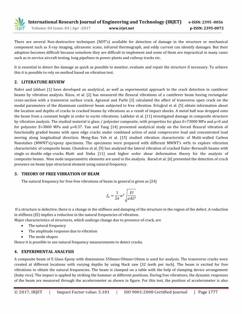
varied in order to extract the signals of vibration. The layout of the sensors on the test specimen is depicted in Figure A data
acquisition system i.e. vibration analyzer is used to record and transfer measured data to the user interference (laptop) for
post processing. Frequency response functions (FRFs) were obtained and analyzed.
Fig-1 Block diagram of experimental setup
A. Steps in experimental analysis
1. A composite beam of E Glass Epoxy was used as a cantilever beam.
2. For cantilever beam the fixed end was made by fixing the beam with the help of baby vise fixed on the table.
3. The connections of the accelerometer, impact hammer, vibration analyzer and user interference (laptop) were
properly made.
4. The cantilever beam was struck with an impact hammer and is excited by means of it.
5. Accelerometer was placed at the different positions on the cantilever beam, to measure the vibration response.
6. All the data was recorded and obtained from the vibrating beam with the help of accelerometer attached to it.
7. The experiments were repeated to check the repeatability of the experimentation.
8. The whole set of data was recorded and then the data was imported into the user interference (Laptop). Further
processing and analysis was done using Virtual unit VA4 Pro software. The signal obtained from the data acquisition
system is used to extract the mode frequencies
9. Repeat impact testing procedures and calculate the natural frequency of the structure by varying following
parameters such as,
a) Location of crack.
b) Depth of crack.
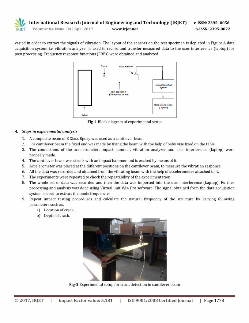
Fig-2 Experimental setup for crack detection in cantilever beam

International Research Journal of Engineering and Technology (IRJET) e-ISSN: 2395 -0056
Volume: 04 Issue: 04 | Apr -2017 www.irjet.net p-ISSN: 2395-0072
© 2017, IRJET | Impact Factor value: 5.181 | ISO 9001:2008 Certified Journal | Page 1779
5. NUMERICAL ANALYSIS
Finite Element Analysis (FEA) approach is widely used these days for numerical analysis. ANSYS is commercial finite element
software package which has capability to analyze a wide range of different problems. Modal Analysis is a tool used to
determine vibration characteristics or natural frequencies of a mechanical structure. It can also be used for dynamic analysis,
harmonic response, and transient dynamic analysis. Modal analysis in ANSYS® is linear analysis. The proposed work is
concentrated on determination of natural frequency of vibration. A Composite beam of dimensions 550mm×50mm×10mm
with 20 layers of epoxy glass fibers having thickness 0.5mm is modeled using ANSYS 16.2. The material properties for woven
glass fabric are considered as E11=25GPa, E22=25GPa, E33=0.6E11, µ=0.2 and modulus of rigidity G=4GPa.The natural frequency
and mode shapes for cantilever conditions with and without crack were analyzed for varying crack depth and crack locations.
Following procedures for a cracked composite beam were followed for the analysis-
A. Steps in numerical analysis
1. Geometry modeling of composite beam.
2. Selection of element type (here SOLSH190 element of 3D modeling is used).
3. Applying material properties to composite beam (Material modeling > Orthotropic properties)
4. Section Lay-up of composite beam. Specify the thickness of layer (0.5mm), orientation (0/90 orientation), number of
integration points.
5. Meshing of model.
6. Apply boundary conditions (one end fixed for cantilever structure) and define number of modes to be extracted.
7. Solution.
8. Perform post processing to read and plot result.
Fig-3 Layers stacking in ANSYS.

International Research Journal of Engineering and Technology (IRJET) e-ISSN: 2395 -0056
Volume: 04 Issue: 04 | Apr -2017 www.irjet.net p-ISSN: 2395-0072
© 2017, IRJET | Impact Factor value: 5.181 | ISO 9001:2008 Certified Journal | Page 1780
Fig-4 Meshed composite cantilever beam model.
6. RESULTS AND DISCUSSION
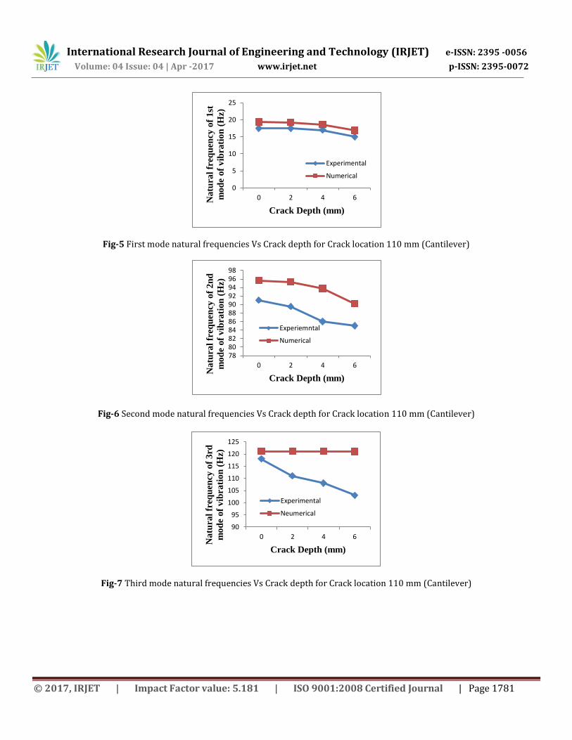
The results obtained from the experimental and numerical analysis on cracked composite plate for crack depth 2 mm, 4 mm
and 6 mm. The length of the crack is also varied as 110mm, 220mm and 330mm from left hand support.
The 1st, 2nd and 3rd mode natural frequencies in case of both cracked and uncracked composite beams for cantilever condition
are shown in Table
Crack Location
(mm)
Crack Depth (mm)
Experimental Numerical
(Hz)
(Hz)
(Hz)
(Hz)
(Hz)
(Hz)
Uncracked
- 17.5 91.0 118 19.390 95.627 121.14
110
2 17.5 89.5 111 19.206 95.260 121.10
4 17.0 86 108 18.573 93.768 121.07
6 15.0 85.0 103 16.866 90.211 120.98
220
2 17 87.5 104 19.312 95.478 120.42
4 16 85.5 102 19.045 94.864 117.89
6 16 84.5 97.5 18.241 93.324 111.23
330
2 17.5 86.5 105 19.369 95.600 120.15
4 17 85 100 19.303 95.456 116.68
6 16 83.5 98.5 19.086 95.066 107.21
Table-1 Natural frequency for both Uncracked and cracked composite cantilever beam.
International Research Journal of Engineering and Technology (IRJET) e-ISSN: 2395 -0056
Volume: 04 Issue: 04 | Apr -2017 www.irjet.net p-ISSN: 2395-0072
© 2017, IRJET | Impact Factor value: 5.181 | ISO 9001:2008 Certified Journal | Page 1781
Fig-5 First mode natural frequencies Vs Crack depth for Crack location 110 mm (Cantilever)
Fig-6 Second mode natural frequencies Vs Crack depth for Crack location 110 mm (Cantilever)
Fig-7 Third mode natural frequencies Vs Crack depth for Crack location 110 mm (Cantilever)
0
5
10
15
20
25
0 2 4 6Na
tura
l fr
eq
uen
cy o
f 1
st
mo
de
of
vib
rati
on
(H
z)
Crack Depth (mm)
Experimental
Numerical
7880828486889092949698
0 2 4 6
Na
tura
l fr
eq
uen
cy o
f 2
nd
mo
de
of
vib
rati
on
(H
z)
Crack Depth (mm)
Experiemntal
Numerical
90
95
100
105
110
115
120
125
0 2 4 6
Na
tura
l fr
eq
uen
cy o
f 3
rd
mo
de
of
vib
rati
on
(H
z)
Crack Depth (mm)
Experimental
Neumerical

International Research Journal of Engineering and Technology (IRJET) e-ISSN: 2395 -0056
Volume: 04 Issue: 04 | Apr -2017 www.irjet.net p-ISSN: 2395-0072
© 2017, IRJET | Impact Factor value: 5.181 | ISO 9001:2008 Certified Journal | Page 1782
Fig-8 FRF of Uncracked cantilever beam
Fig-10 FRF of cracked cantilever beam at 110mm and depth 2mm.

International Research Journal of Engineering and Technology (IRJET) e-ISSN: 2395 -0056
Volume: 04 Issue: 04 | Apr -2017 www.irjet.net p-ISSN: 2395-0072
© 2017, IRJET | Impact Factor value: 5.181 | ISO 9001:2008 Certified Journal | Page 1783
Fig-9 FRF of cracked cantilever beam at 110mm & depth 4mm.
Fig-11 FRF of cracked cantilever beam at 110mm & depth 6mm.
Fig-12 Deformed shape for 1st mode of vibration of composite cantilever beam for crack at 110mm and depth 2mm.

International Research Journal of Engineering and Technology (IRJET) e-ISSN: 2395 -0056
Volume: 04 Issue: 04 | Apr -2017 www.irjet.net p-ISSN: 2395-0072
© 2017, IRJET | Impact Factor value: 5.181 | ISO 9001:2008 Certified Journal | Page 1784
Fig-13 Deformed shape for 2nd mode of vibration of composite cantilever beam for crack at 110mm and depth 4mm.
Fig-14 Deformed shape for 3rd mode of vibration of composite cantilever beam for crack at 110mm and depth 6mm.
7. CONCLUSION It can be seen that the natural frequencies for cantilever conditions decrease with the introduction of a crack. It can be
concluded that the natural frequency of vibration of the composite plate decreases with increase in depth of the crack. The
natural frequency of the beam decreases with increase in length of the crack from left hand fixed end till the mid span of
beam and again starts increasing towards free end.
REFERENCES
[1] Nahvi H. and Jabbari M., Crack detection in beams using experimental modal data and finite element model, International
Journal of Mechanical Sciences 47, (2005), pp.1477–1497.
[2] Rizos P.F., Aspragathos N., and Dimarogonas A.D., Identification of cracked location and magnitude in a cantilever beam
from the vibrational modes, Journal of Sound and Vibration, 138 (3), (1989), pp.381 – 388.
[3] D. K. Agrawal, D. R. Parhi, Effect of Crack on Modal Parameters of Cantilever Beam Subjected to Vibration, Elsevier
Procedia Engineering, 51, 2013,pp. 665-669.
[4] Ertuğrul Çam, Orhan Sadettin and Lüy Murat , An analysis of cracked beam structure using impact echo method, NDT and
E International 38, (2005), pp.368–373.
[5] M. Lakhdar, D. Mohammed, L. Boudjemaa, A. Rabia, M. Bachir, Damage Detection in a Comosite Structure by Vibration
Analysis, Elsevier Energy Procedia, 36, 2013,pp.888-897.
[6] T. Yan. J. Yang, Forced Vibration of Edge Cracked Functionally Graded Beams due to Transverse Moving Load., Elsevier
Prpcedia Engineering, 14, 2011, pp.3293-3300.
[7] Meng-Kao Yeh, Nyan-Hwa Tai, Dong-Syuan Lin, Vibration analysis of Multi Walled Carbon Nanotubes / epoxy composite
beam. Elsevier Procedia Engineering, 79, 2014, pp.244-248.
[8] Chondros T.G, Dimarogonas A.D and Yao, J.A. Continuos Cracked Beam Vibration Theory, Journal of Sound and Vibration,
215,(1998), pp.17-34
[9] Dipak Kr. Maiti & P. K. Sinha. Bending and free vibration analysis of shear deformable laminated composite beams
by finite element method. Composite Structures, 29, 1994, pp.421-431.
International Research Journal of Engineering and Technology (IRJET) e-ISSN: 2395 -0056
Volume: 04 Issue: 04 | Apr -2017 www.irjet.net p-ISSN: 2395-0072
© 2017, IRJET | Impact Factor value: 5.181 | ISO 9001:2008 Certified Journal | Page 1785
[10] K. H. Barad, D. S. Sharma,V.Vyas , Crack Detection in Cantilever Beam by Frequency based method, Elsevier Procedia
Engineering, 51, 2013, pp.770-775.
[11] J. S. Rao and K. Gupta, Theory and Practice of Mechanical Vibrations, New Age International Publishers.


