CROWN AND BRIDGE RESTORATIONS WITHTHE SYNOCTA® PROSTHETIC SYSTEM

Straumann is the industrial partner of the ITI (International Team for Implantology) in the areas of research, development, and education.
�
CONTENTS 1. Introduction 4
2. Advantage 5
�. System Overview 6
4. synOcta® Abutments – Overview 8
5. Impression procedure with the synOcta® prosthetic system 10
5.a Closed tray impression procedure “snap-on” 12
5.b Open tray impression procedure “screwed” 1�
6. Bite registration 14
7. Temporary restorations 16
8. Fabricating the master cast 18
9. Case planning with the prosthetic planning kit 20
10.a synOcta® 1.5 screw-retained Abutments for transocclusal screw-retained crowns and bridges 22
10.b synOcta® cemented Abutments for cement-retained crowns and bridges 26
10.c synOcta® Angled for RN 15° and 20° angled abutments for screw-retained and cement-retained crowns and bridges �1
10.d synOcta® Angled for WN 15° angled abutment for cement-retained crowns and bridges �6
10.e synOcta® Transversal (TS for RN) Abutment for transversal screw-retained crowns and bridges 40
11. synOcta® gold abutment for RN The one-piece solution for anterior zone esthetics 49
12. Meso abutment Step-by-step 56
1�. Processing instructions 58
4
1. INTRODuCTION
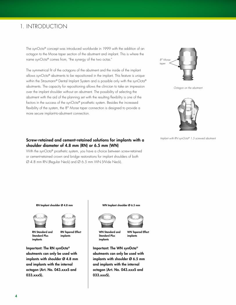
Implant with RN synOcta® 1.5 screwed abutment
The synOcta® concept was introduced worldwide in 1999 with the addition of an octagon to the Morse taper section of the abutment and implant. This is where the name synOcta® comes from, “the synergy of the two octas.”
The symmetrical fit of the octagons of the abutment and the inside of the implant allows synOcta® abutments to be repositioned in the implant. This feature is unique within the Straumann® Dental Implant System and is possible only with the synOcta® abutments. The capacity for repositioning allows the clinician to take an impression over the implant shoulder without an abutment. The possibility of selecting the abutment with the aid of the planning set with the resulting flexibility is one of the factors in the success of the synOcta® prosthetic system. Besides the increased flexibility of the system, the 8° Morse taper connection is designed to provide a more secure implant-to-abutment connection.
Screw-retained and cement-retained solutions for implants with a shoulder diameter of 4.8 mm (RN) or 6.5 mm (WN)With the synOcta® prosthetic system, you have a choice between screw-retained or cement-retained crown and bridge restorations for implant shoulders of both Ø 4.8 mm RN (Regular Neck) and Ø 6.5 mm WN (Wide Neck).
Octagon on the abutment
8° Morse taper
Important: The RN synOcta® abutments can only be used with implants with shoulder Ø 4.8 mm and implants with the internal octagon (Art. No. 04�.xxxS and 0��.xxxS).
Important: The WN synOcta® abutments can only be used with implants with shoulder Ø 6.5 mm and implants with the internal octagon (Art. No. 04�.xxxS and 0��.xxxS).
RN Implant shoulder Ø 4.8 mm
RN Standard andStandard Plusimplants
RN Tapered Effectimplants
WN Implant shoulder Ø 6.5 mm
WN Standard andStandard Plusimplants
WN Tapered Effectimplants
5
Reliable. Simple. Flexible.The synOcta® prosthetic system offers clinicians the advantages of a reliable, simple and flexible prosthetic solution.
The secret of synOcta®’s success exists in the implant-to-abutment connection. The precise fit of the abutment octagon in the implant octagon allows the abutment to be precisely repositioned from the master cast to the mouth.
Reliableß The 8° cone of the Morse taper offers an ideal combination between cold welding
and reliable vertical positioningß Virtually no abutment loosening
Simpleß Simple impression taking without the abutmentß Simple options for provisionalization
Flexibleß Abutments can be repositioned from master cast to the mouthß Abutment selection on the model with prosthetic planning kitß Restorative options with comprehensive abutment range
2. ADVANTAGE
Important: Please note the description of the indication for each implant type. You will find this in the current product catalog, in “SURGICAL, Basic information on surgical procedure with the Straumann® Dental Implant System” (USLIT 100), and in the instructions for use enclosed with the implants.
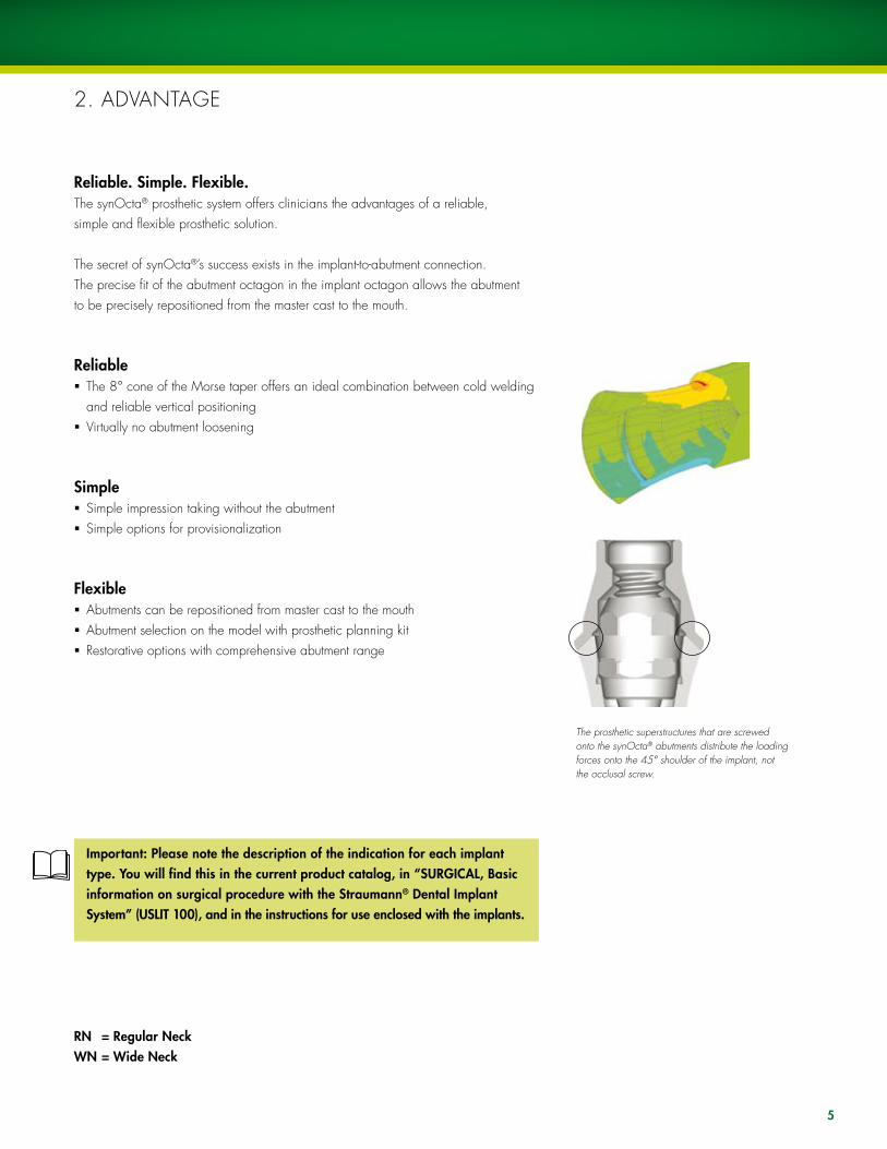
The prosthetic superstructures that are screwed onto the synOcta® abutments distribute the loading forces onto the 45° shoulder of the implant, not the occlusal screw.
RN = Regular Neck WN = Wide Neck
••• 048.214 •• /241 • /240
••• 048.204
048.350V4 048.360V4 048.361V4
048.602
•• 048.632
••/••• 048.227
• 048.633
• 048.642
• 048.229
048.921V4
048.620
• 048.651
048.634
048.665
04 9. 15 4
u 048.916/917/918/919V4
u 048.612/613/617/618
u 048.922/923/924/925V4
u/•• 048.610/611/615/616
048.676V4
048.350V4
048.670
048.930V4
048.60 5
•• 048.650
•• 048.638
•• 048.666
048.350 048.361V4
048.032 048.054 V4
048.931V4
048.603
• 048.639
• 048.667
048.933V4
048.608
048.678
048.934V 4
048.609
• 048.233
048.171
048.091
048.932V4
048.606
•• 048.234
048.095
048.6 72
048.000 V4 048.059 V4 048.003 V4 048.002 V4
•• 048.662
• 048.663
048.013
•• 048.244
• 048.243
048.090
048.929V4
048.010
048.124
048.070V4 048.017V4
Ø 6.5 mm
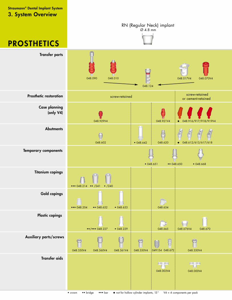
screw-retained cement-retained screw-retained or cement-retained
screw-retained or cement-retained cement-retained screw-retained
i • crown •• bridge ••• bar u not f or hollow cylinder mplants, 15 ° V4 = 4 components per pac k
WN ( W ide Neck) implant
Prosthetic restoratio n
Case planning (only V4)
Abutments
Te m porar y components
Titanium copings
Gold copings
Plastic copings
Auxiliar y par ts/screws
Tr ansfer aids
T ransfer par ts
PROSTHETIC S
Straumann ® Dental I mplant Syste m
3. System Overview
Ø 4.8 mm RN (Regular Neck) implant
• 048.561
048.350V4
• 048.668
• 048.560

••• 048.214 •• /241 • /240
••• 048.204
048.350V4 048.360V4 048.361V4
048.602
•• 048.632
••/••• 048.227
• 048.633
• 048.642
• 048.229
048.921V4
048.620
• 048.651
048.634
048.665
04 9. 15 4
u 048.916/917/918/919V4
u 048.612/613/617/618
u 048.922/923/924/925V4
u/•• 048.610/611/615/616
048.676V4
048.350V4
048.670
048.930V4
048.60 5
•• 048.650
•• 048.638
•• 048.666
048.350 048.361V4
048.032 048.054 V4
048.931V4
048.603
• 048.639
• 048.667
048.933V4
048.608
048.678
048.934V 4
048.609
• 048.233
048.171
048.091
048.932V4
048.606
•• 048.234
048.095
048.6 72
048.000 V4 048.059 V4 048.003 V4 048.002 V4
•• 048.662
• 048.663
048.013
•• 048.244
• 048.243
048.090
048.929V4
048.010
048.124
048.070V4 048.017V4
Ø 6.5 mm
screw-retained cement-retained screw-retained or cement-retained
screw-retained or cement-retained cement-retained screw-retained
i • crown •• bridge ••• bar u not f or hollow cylinder mplants, 15 ° V4 = 4 components per pac k
WN ( W ide Neck) implant
Prosthetic restoratio n
Case planning (only V4)
Abutments
Te m porar y components
Titanium copings
Gold copings
Plastic copings
Auxiliar y par ts/screws
Tr ansfer aids
T ransfer par ts
PROSTHETIC S
Straumann ® Dental I mplant Syste m
3. System Overview
Ø 4.8 mm RN (Regular Neck) implant
• 048.561
048.350V4
• 048.668
• 048.560
8
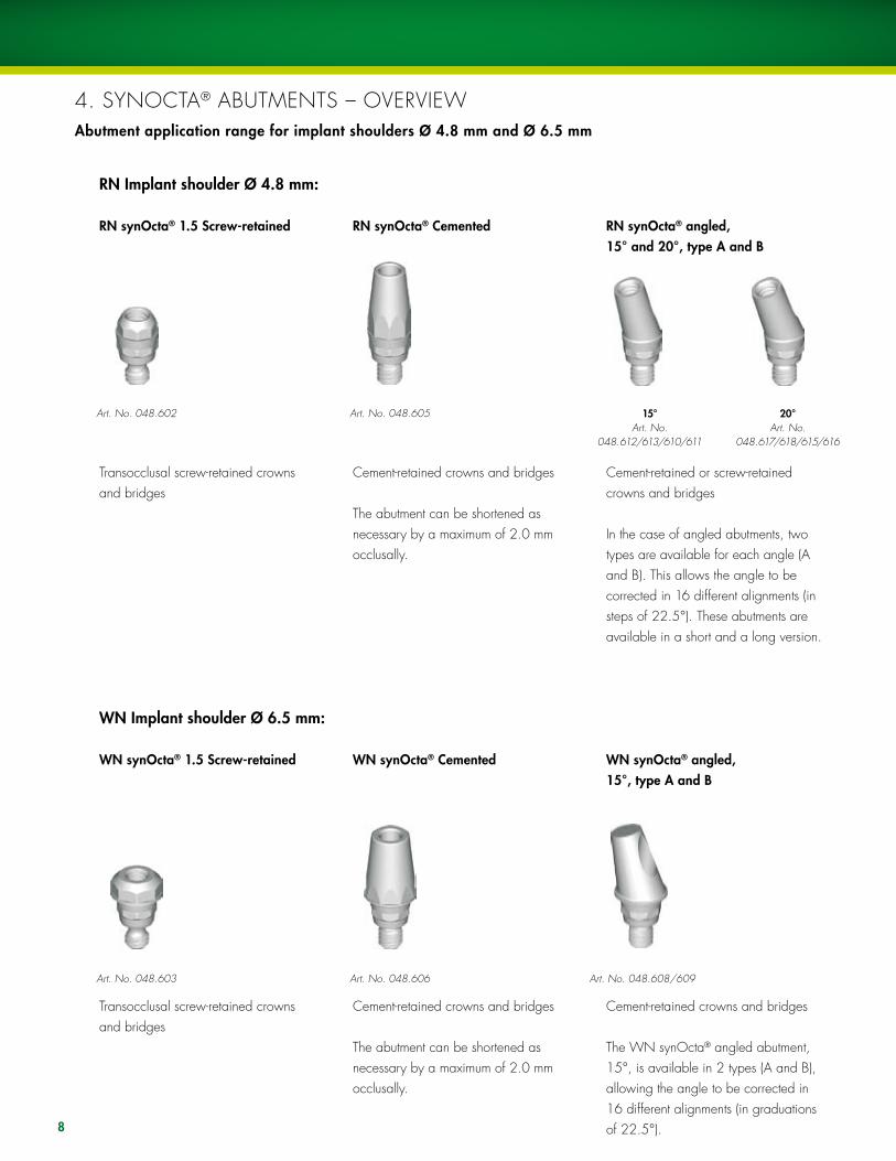
4. SyNOCTA® ABuTMENTS – OVERVIEWAbutment application range for implant shoulders Ø 4.8 mm and Ø 6.5 mm
RN synOcta® 1.5 Screw-retained
Transocclusal screw-retained crowns and bridges
RN synOcta® Cemented
Cement-retained crowns and bridges
The abutment can be shortened as necessary by a maximum of 2.0 mm occlusally.
RN synOcta® angled, 15° and 20°, type A and B
Cement-retained or screw-retained crowns and bridges
In the case of angled abutments, two types are available for each angle (A and B). This allows the angle to be corrected in 16 different alignments (in steps of 22.5°). These abutments are available in a short and a long version.
Art. No. 048.602 Art. No. 048.605 15°Art. No.
048.612/613/610/611
20°Art. No.
048.617/618/615/616
WN synOcta® 1.5 Screw-retained
Transocclusal screw-retained crowns and bridges
WN synOcta® Cemented
Cement-retained crowns and bridges
The abutment can be shortened as necessary by a maximum of 2.0 mm occlusally.
WN synOcta® angled, 15°, type A and B
Cement-retained crowns and bridges
The WN synOcta® angled abutment, 15°, is available in 2 types (A and B), allowing the angle to be corrected in 16 different alignments (in graduations of 22.5°).
Art. No. 048.603 Art. No. 048.606 Art. No. 048.608/609
RN Implant shoulder Ø 4.8 mm:
WN Implant shoulder Ø 6.5 mm:

9
Art. No. 048.620 Art. No. 048.642
RN synOcta® meso abutment
For the fabrication of a meso structure for cement-retained crowns The synOcta® meso abutment is made of titanium.
Art. No. 048.560
RN synOcta® gold abutment
Transocclusal screw-retained crowns, and for the production of a meso structure for cement-retained crowns The gold abutment is a combination of coping and abutment in one piece.
RN synOcta® transversal (TS)
Transversal screw-retained crowns and bridges
The RN synOcta® TS abutment has two transversal openings. One screw opening is aligned with the flat wall of the octagon, while a second screw opening is aligned with the apex, enabling the transversal screw to be aligned in 16 different directions (in steps of 22.5°).
WN synOcta® meso abutment
For the fabrication of a meso structure for cement-retained crowns The synOcta® meso abutment is made of titanium.
Art. No. 048.561
SterilizationStraumann abutments and components are not sterile when delivered. Please use the following procedure for sterilization prior to use.
Material Method ConditionsTi, Ti alloy, PEEK, Autoclave, 134˚C (273˚F), 18 min.PEEK with Ti inlay moist heat
Note: Parts that have been modified or altered from their original state may require different sterilization procedures.
To prevent tension cracks in PMMA products do not use the following: alcohol; uV radiation; sterilization; immersion in liquid for more than one hour; temperatures over 60˚C (140˚F).

10
5. IMPRESSION PROCEDuRE WITH THE SyNOCTA® PROSTHETIC SySTEM
OPEN TRAY CLOSED TRAY
Art. No. 048.070V4Art. No. 048.090 Art. No. 048.010
There are two options available for taking an impression on RN and WN implant shoulders Ø 4.8 mm and Ø 6.5 mm:ß the open tray technique “screwed”ß the closed tray technique “snap-on”
The closed tray option can be regarded as the standard version. The impression cap can easily “snap” into place and be used in most cases.
RN = Regular NeckWN = Wide Neck
The open tray version is indicated particularly in cases where the implant shoulder is placed very deeply (more than 3.0 mm subgingival) and where the gingiva is very close. In this case, the open tray impression procedure is advantageous; the impression cap is screwed tightly and precisely to the implant, and loosening of the impression cap following displacement by the gingiva is avoided.
COLOR CODING
RN synOcta® impression components on implant shoulder Ø 4.8 mm = red
WN synOcta® impression components on implant shoulder Ø 6.5 mm = white
Art. No. 048.091
Ø 4.8 mm RN Ø 6.5 mm WN
Ø 4.8 mm RN Ø 6.5 mm WN
Art. No. 048.171Art. No. 048.124
Art. No. 048.095
Art. No. 048.017V4 Art. No. 048.013
Ø 4.8 mm RN Ø 6.5 mm WN

11

�a
�b
12
5.A ClOSED TRAy IMPRESSION PROCEDuRE “SNAP-ON”
The closed-tray impression-taking procedure for implant shoulder Ø 4.8 mm RN and implant shoulder Ø 6.5 mm WN is identical.
All parts of the transfer system are supplied non-sterile. The parts can be disinfected as required using standard commercial disinfectants that are suitable for plastic products. Follow the manufacturer’s instructions.
Caution: The plastic components are for single use only. They must not be sterilized. In order to prevent damage to the plastic components (loss of elasticity or embrittlement), they must be protected from strong light and heat.
Art. No. 048.070V4 Art. No. 048.017V4 Art. No. 048.124 Art. No. 048.095 Art. No. 048.013 Art. No. 048.171
RN Implant shoulder Ø 4.8 mm WN Implant shoulder Ø 6.5 mm
1. Positioning of the impression capBoth the implant shoulder and the internal configuration must be cleaned of blood and tissue prior to the impression procedure. Push the RN impression cap (048.017V4) onto the implant shoulder until it clicks into place. Gently turn the impression cap to ensure it is in the correct position. When the cap is in the correct position, it can be rotated on the implant.
Important: The shoulder and the margin of the impression cap must not be damaged to ensure accuracy of the impression procedure.
2. Insertion of the positioning cylinderThe octagon of the RN synOcta® positioning cylinder must be properly aligned with the octagon in the implant and pushed into the impression cap until it meets the flat part of the impression cap.
�. Impression takingThe impression is taken using an elastomeric impression material (polyvinyl siloxane or polyether rubber).
Important: Due to its low tensile strength, hydrocolloid is not suitable for this application.
click
No gap

1
�a
2
�b
1�
5.B OPEN TRAy IMPRESSION PROCEDuRE “SCREWED”
The open tray impression-taking procedure is identical for implant shoulder Ø 4.8 mm RN and implant shoulder Ø 6.5 mm WN.
For this impression procedure use a custom-made tray with perforations. A standard tray with appropriate perforations may also be used.
Important: Only the integral screw must be used. The margin and the octagon must not be damaged to ensure accuracy of the transfer procedure. For this reason, the impression caps are intended for single use only.
RN Implant shoulder Ø 4.8 mm WN Implant shoulder Ø 6.5 mm
A) Positioning of the impression cap
Both the implant shoulder and the internal configuration must be cleaned of blood and tissue prior to the impression procedure. Place the RN synOcta® impression cap (048.010) onto the implant shoulder and tighten it with the integral guide screw and a SCS screwdriver. It is important to accurately position the octagon of the coping with the internal configuration of the implant before tightening the screw.
Option: If interocclusal space is adequate, the impression can also be taken with the open tray RN synOcta® impression cap with built-in handle (048.090). The external octagon on the coping must be lined up with the internal octagon of the implant.
B) Impression taking
1. The custom-made tray (light-cured resin) contains perforations for the guide screws.
�. Once cured, the guide screw is loosened and the impression is removed with the aid of a SCS screwdriver.
2. The impression is taken using an elastomeric impression material (polyvinyl siloxane or polyether rubber).
Important: Due to its low tensile strength, hydrocolloid is not suitable for this application.
Art. No.048.010
Art. No.048.090
Art. No.048.124
Art. No.048.091
Art. No.048.171
1 2
�a �b
14
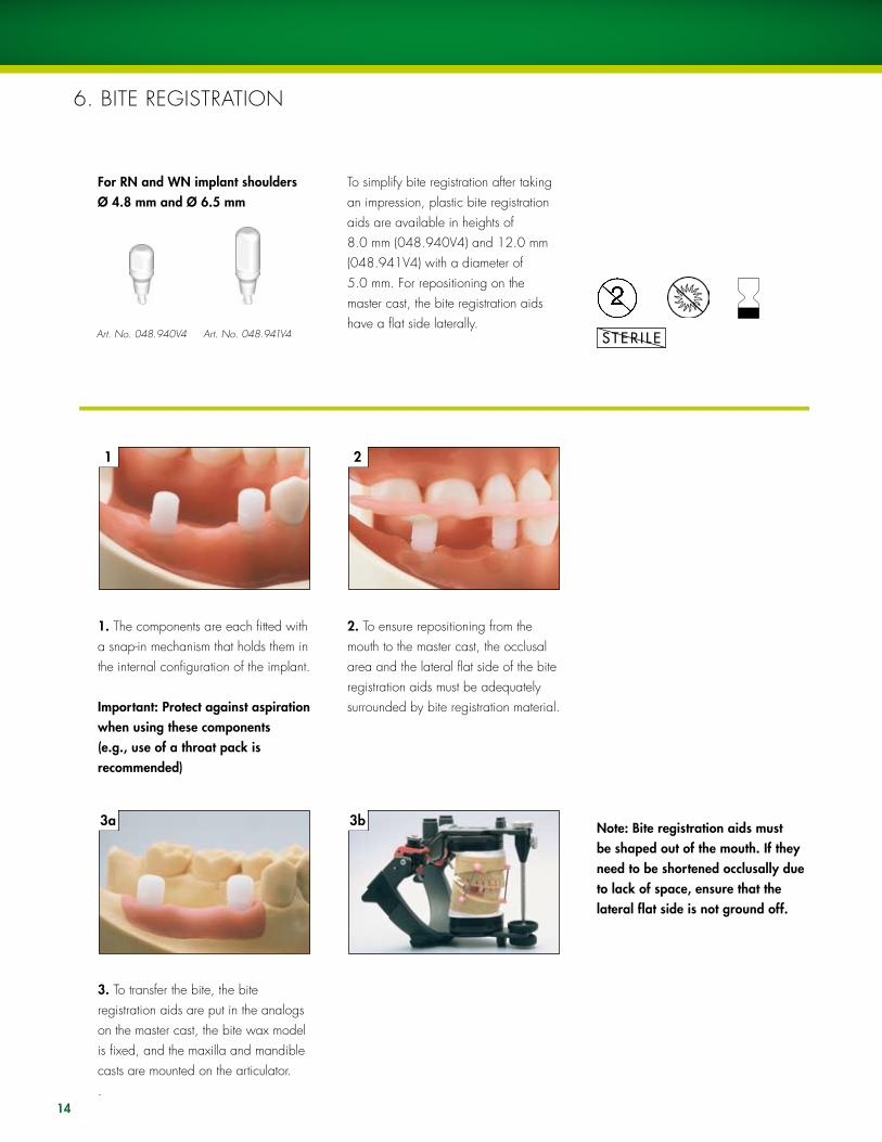
6. BITE REGISTRATION
To simplify bite registration after taking an impression, plastic bite registration aids are available in heights of 8.0 mm (048.940V4) and 12.0 mm (048.941V4) with a diameter of 5.0 mm. For repositioning on the master cast, the bite registration aids have a flat side laterally.
Art. No. 048.940V4 Art. No. 048.941V4
For RN and WN implant shouldersØ 4.8 mm and Ø 6.5 mm
1. The components are each fitted with a snap-in mechanism that holds them in the internal configuration of the implant.
Important: Protect against aspiration when using these components (e.g., use of a throat pack is recommended)
2. To ensure repositioning from the mouth to the master cast, the occlusal area and the lateral flat side of the bite registration aids must be adequately surrounded by bite registration material.
�. To transfer the bite, the bite registration aids are put in the analogs on the master cast, the bite wax model is fixed, and the maxilla and mandible casts are mounted on the articulator..
Note: Bite registration aids must be shaped out of the mouth. If they need to be shortened occlusally due to lack of space, ensure that the lateral flat side is not ground off.

15
16
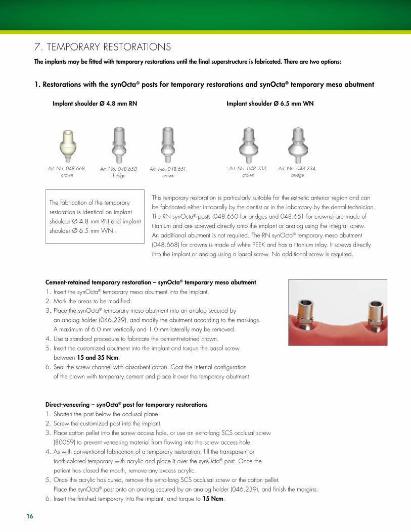
7. TEMPORARy RESTORATIONSThe implants may be fitted with temporary restorations until the final superstructure is fabricated. There are two options:
Cement-retained temporary restoration – synOcta® temporary meso abutment1. Insert the synOcta® temporary meso abutment into the implant.2. Mark the areas to be modified.3. Place the synOcta® temporary meso abutment into an analog secured by an analog holder (046.239), and modify the abutment according to the markings. A maximum of 6.0 mm vertically and 1.0 mm laterally may be removed.4. use a standard procedure to fabricate the cement-retained crown.5. Insert the customized abutment into the implant and torque the basal screw between 15 and �5 Ncm.6. Seal the screw channel with absorbent cotton. Coat the internal configuration of the crown with temporary cement and place it over the temporary abutment.
Direct-veneering – synOcta® post for temporary restorations1. Shorten the post below the occlusal plane.2. Screw the customized post into the implant.3. Place cotton pellet into the screw access hole, or use an extra-long SCS occlusal screw (80059) to prevent veneering material from flowing into the screw access hole.4. As with conventional fabrication of a temporary restoration, fill the transparent or tooth-colored temporary with acrylic and place it over the synOcta® post. Once the patient has closed the mouth, remove any excess acrylic.5. Once the acrylic has cured, remove the extra-long SCS occlusal screw or the cotton pellet. Place the synOcta® post onto an analog secured by an analog holder (046.239), and finish the margins. 6. Insert the finished temporary into the implant, and torque to 15 Ncm.
1. Restorations with the synOcta® posts for temporary restorations and synOcta® temporary meso abutment
The fabrication of the temporary restoration is identical on implant shoulder Ø 4.8 mm RN and implant shoulder Ø 6.5 mm WN.
This temporary restoration is particularly suitable for the esthetic anterior region and can be fabricated either intraorally by the dentist or in the laboratory by the dental technician. The RN synOcta® posts (048.650 for bridges and 048.651 for crowns) are made of titanium and are screwed directly onto the implant or analog using the integral screw. An additional abutment is not required. The RN synOcta® temporary meso abutment (048.668) for crowns is made of white PEEK and has a titanium inlay. It screws directly into the implant or analog using a basal screw. No additional screw is required.
Art. No. 048.650,bridge
Art. No. 048.651,crown
Implant shoulder Ø 4.8 mm RN Implant shoulder Ø 6.5 mm WN
Art. No. 048.233,crown
Art. No. 048.234,bridge
Art. No. 048.668,crown

17
Fabrication in the laboratory:The posts can be veneered either by grinding out prefabricated acrylic teeth or by waxing up and investing. This method is especially useful if a silicone key of the wax-up is available. The titanium posts should be silanized to improve bonding of the composite. The temporary restoration is fabricated using veneering composite.
Important: The synOcta® posts and RN synOcta® temporary meso abutments must not remain in situ for longer than 6 months and the restoration must always be out of occlusion in order to reduce the lateral forces that occur.
Important: Prefabricated titanium posts cannot be used for cast-on techniques.
2. Use of the closure screw/healing cap
With this option, the closure screw that was used during the healing period is replaced following the impression procedure. This version is particularly suitable when an existing prosthesis (full or partial denture) has been used as a temporary restoration or if the gap in the teeth is in the posterior region and therefore does not affect esthetics.
Direct-veneering – synOcta® temporary meso abutment1. Insert the synOcta® temporary meso abutment into an implant.2. Mark the areas to be modified.3. Place the synOcta® temporary meso abutment into an analog secured by an analog holder (046.239), and modify the abutment according to the markings. A maximum of 6.0 mm vertically and 1.0 mm laterally may be removed.4. For additional mechanical retention, sandblast the PEEK portion of the abutment, or use a bonding agent. 5. Screw the customized abutment into the implant.6. Place cotton pellet into the screw access hole, or use an extra-long SCS occlusal screw (80059) to prevent veneering material from flowing into the screw access hole.7. As with conventional fabrication of a temporary restoration, fill the transparent or tooth-colored temporary with acrylic and place it over the synOcta® temporary meso abutment. Once the patient has closed the mouth, remove any excess acrylic.8. Once the acrylic has cured, remove the extra-long SCS occlusal screw or the cotton pellet. Place the synOcta® temporary meso abutment into an analog secured by an analog holder (046.239), and finish the margins.9. Insert the finished temporary abutment into the implant, torque the basal screw between 15 and �5 Ncm, and fill the screw access hole with acrylic.

18
8. FABRICATING THE MASTER CAST
The fabrication of the master cast is identical for implant shoulder Ø 4.8 mm RN and implant shoulder Ø 6.5 mm WN.
Art. No. 048.124
Implant shoulder Ø 4.8 mm RN
Art. No. 048.171
Implant shoulder Ø 6.5 mm WN
Important: To ensure accuracy when taking the impression, the analog in both versions must be connected exactly with the octagon of the impression components before snapping it on or screwing it in.
Closed tray technique (snap-on):In the laboratory, the RN synOcta® analog (048.124) is repositioned in the impression. The shoulder must click audibly into place. The red RN synOcta® positioning cylinder indicates to the dental technician that the RN synOcta® analog with the red line must be used.
Analogs for:
COLOR CODING
RN synOcta® impression components on implant shoulder Ø 4.8 mm = red
WN synOcta® impression components on implant shoulder Ø 6.5 mm = white

19
Open tray technique (screwed):The RN synOcta® analog is fixed in the impression using the integral guide screw. The red RN synOcta® impression cap indicates to the dental technician that the RN synOcta® analog with the red line must be used.
Important: When tightening the screw, grasp the retentive section of the analog in order to prevent the impression cap from rotating. This is especially important if the cap has been shortened.
Fabrication of working model:
Tip: A gingival mask should always be used to ensure that the emergence profile of the crown is contoured optimally. This is essential for restorations in esthetically demanding regions, and with subgingival crown margins.
Conventional fabrication of the working model using special hard plaster type 4 (DIN 13911)
20
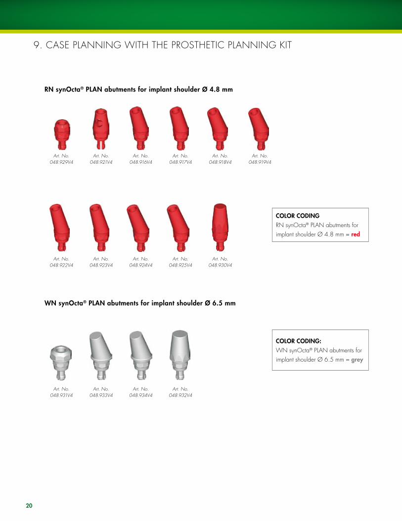
9. CASE PlANNING WITH THE PROSTHETIC PlANNING KIT
COLOR CODINGRN synOcta® PlAN abutments for implant shoulder Ø 4.8 mm = red
COLOR CODING:WN synOcta® PlAN abutments for implant shoulder Ø 6.5 mm = grey
Art. No.048.929V4
Art. No.048.921V4
Art. No.048.916V4
Art. No.048.917V4
Art. No.048.918V4
Art. No.048.919V4
RN synOcta® PLAN abutments for implant shoulder Ø 4.8 mm
Art. No.048.922V4
Art. No.048.923V4
Art. No.048.924V4
Art. No.048.925V4
Art. No.048.930V4
WN synOcta® PLAN abutments for implant shoulder Ø 6.5 mm
Art. No.048.931V4
Art. No.048.933V4
Art. No.048.934V4
Art. No.048.932V4

21
The prosthetic planning kit (048.901) allows for optimal planning of the restoration on the model. This gives the dentist and dental technician the greatest flexibility in cooperative planning and also minimizes the number of components that need to be stocked.
This prosthetic planning kit contains plastic abutments for crown and bridge restorations that can be placed on the analogs in order to check the height, axial alignment and screw axis. This also makes it easy to determine which of the angled abutments offers the best solution.
Caution: These PLAN abutments are only for use on the model and must not be used intraorally.

22
10.A SyNOCTA® 1.5 SCREW-RETAINEDAbutments for transocclusal screw-retained crowns and bridges
Art. No. 048.632RN synOcta® gold coping without internal octagon for bridge, for use with
048.602(includes modeling aid)
Art. No. 048.633RN synOcta® gold coping
with internal octagon for crown, for use with
048.602(includes modeling aid)
Art. No. 048.602
Implant shoulder Ø 4.8 mm RN
Art. No. 048.603
Implant shoulder Ø 6.5 mm WN
Inserting the abutmentThe original abutment is put on the analog and aligned in the octagon.
Important: The abutment must be properly positioned in the octagon before the screw is tightened.
The screw is tightened by hand using the SCS screwdriver.
B) Process of the copings
Version 1: synOcta® gold copings for the cast-on techniqueThe gold copings are made of a non-oxidizing high-fusing alloy (Ceramicor®: Au 60 %, Pt 19 %, Pd 20 %, Ir 1%; melting range 1400° – 1490 °C, 2552° – 2714 °F). With these copings, the modeling aid (burn-out plastic) is already in place. The modeling aid can be shortened if necessary.
Tip: Never cast without the modeling aid. Otherwise the metal-ceramic alloy will not flow at all or will be too thin at the upper edge of the coping (screw seating on the coping), leading to a risk of cracks appearing in the ceramic due to different heat expansion coefficients. The modeling aid also ensures that the end of the screw channel is clean and sharp-edged.
Art. No. 048.638WN synOcta® gold
coping without internal octagon for bridge, for
use with 048.603 (includes modeling aid)
Art. No. 048.639WN synOcta® gold
coping with internal oc-tagon for crown, for use
with 048.603 (includes modeling aid)
A) Fabrication of the superstructure

1 2 �
2�
1. Position the selected coping (gold or plastic), then secure with a SCS occlusal screw or SCS guide screw. Depending on the individual circumstances, the modeling aid, plastic coping and/or the guide screw may need to be shortened to the height of the occlusal plane.
2. Wax up the framework in the conventional manner for veneers (plastic/porcelain). use the silicone key of the wax-up to check the framework shape. The modeling is carried out on a scaled-down tooth shape. The crowns must be premolarized in size to reduce the risk of nonaxial loading and prevent plaque accumulation due to overcontouring.
�. When waxing up the framework, ensure that those areas of the prefabri-cated gold copings that are to be veneered with porcelain are coated with wax (at least 0.7 mm). As the gold coping consists of a non-oxidizing alloy, the porcelain cannot be bonded directly onto it (no oxidation for bonding).
Important: Do not cover the delicate margin of the copings with wax. The use of investment material for rapid heating methods (speed investment methods) is not recommended. Do not use wetting agents.
Tip: Before investment, it is recommended that the delicate margin is cleaned with a cotton bud (dipped in alcohol) as even minimal wax residue here can lead to overflow of the cast-on alloy onto the edge or into the interior of the coping.
1 2 3
24
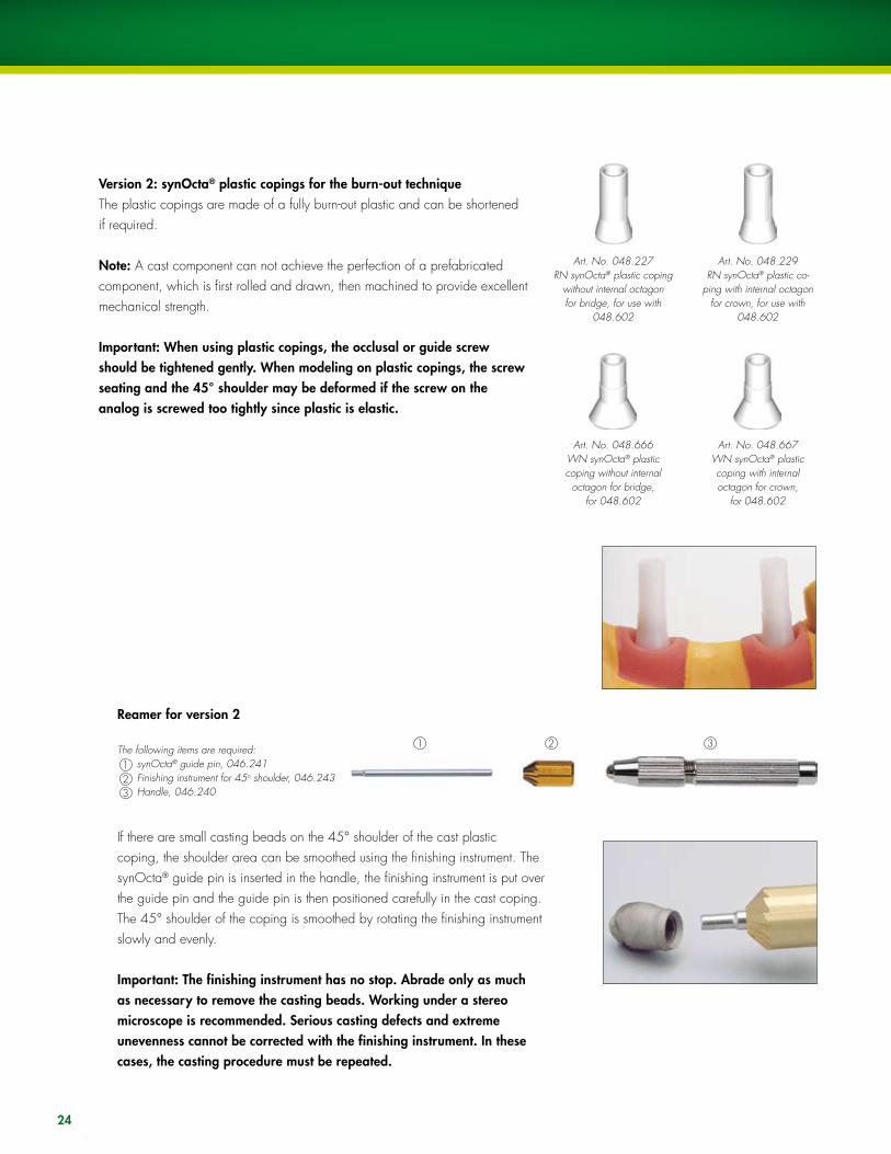
Version 2: synOcta® plastic copings for the burn-out techniqueThe plastic copings are made of a fully burn-out plastic and can be shortened if required.
Note: A cast component can not achieve the perfection of a prefabricated component, which is first rolled and drawn, then machined to provide excellent mechanical strength.
Important: When using plastic copings, the occlusal or guide screw should be tightened gently. When modeling on plastic copings, the screw seating and the 45° shoulder may be deformed if the screw on the analog is screwed too tightly since plastic is elastic.
Reamer for version 2
The following items are required:1 synOcta® guide pin, 046.2412 Finishing instrument for 45o shoulder, 046.2433 Handle, 046.240
If there are small casting beads on the 45° shoulder of the cast plastic coping, the shoulder area can be smoothed using the finishing instrument. The synOcta® guide pin is inserted in the handle, the finishing instrument is put over the guide pin and the guide pin is then positioned carefully in the cast coping. The 45° shoulder of the coping is smoothed by rotating the finishing instrument slowly and evenly.
Important: The finishing instrument has no stop. Abrade only as much as necessary to remove the casting beads. Working under a stereo microscope is recommended. Serious casting defects and extreme unevenness cannot be corrected with the finishing instrument. In these cases, the casting procedure must be repeated.
Art. No. 048.227RN synOcta® plastic coping
without internal octagon for bridge, for use with
048.602
Art. No. 048.229RN synOcta® plastic co-
ping with internal octagon for crown, for use with
048.602
Art. No. 048.666WN synOcta® plastic coping without internal
octagon for bridge, for 048.602
Art. No. 048.667WN synOcta® plastic coping with internal octagon for crown,
for 048.602

25
SCS occlusal screwArt. No. 048.350V4
SCS guide screwArt. No.
048.360V4/361/362/363/364
See also CD-ROM “Straumann® Dental Implant System-Prosthetics,” Art. No. 150.5�8: Screw-retained single tooth restoration with the RN synOcta® 1.5 screw-retained abutment.
Tighten the superstructure on the synOcta® 1.5 abutment with a torque of 15 Ncm. The following options are available for securing the superstructure:
Version 1: Securing with the SCS occlusal screwWith this option, cover the screw heads with a little wax or gutta percha and seal the transocclusal screw channels (e.g., with composite).
Tightening torque = 15 Ncm
Version 2: Securing with the SCS guide screwWith this option, shorten the SCS guide screw intraorally to the occlusal plane, and cover.
Tightening torque = 15 Ncm
26
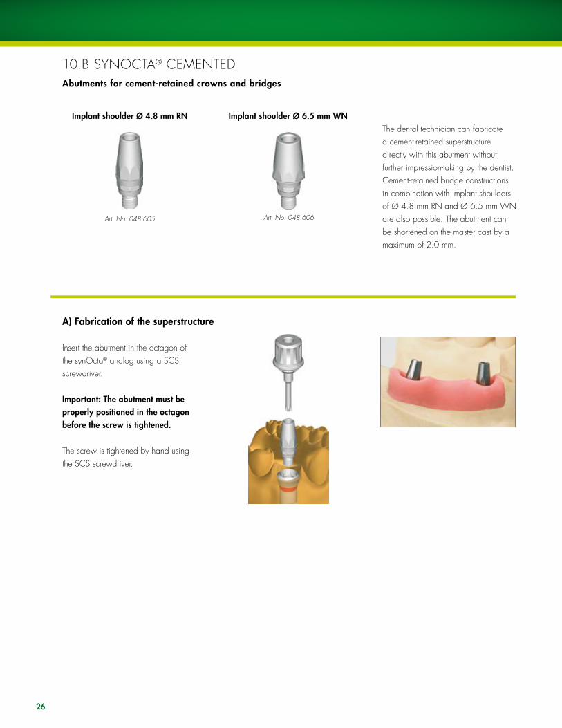
10.B SyNOCTA® CEMENTEDAbutments for cement-retained crowns and bridges
Art. No. 048.605
Insert the abutment in the octagon of the synOcta® analog using a SCS screwdriver.
Important: The abutment must be properly positioned in the octagon before the screw is tightened.
The screw is tightened by hand using the SCS screwdriver.
Implant shoulder Ø 4.8 mm RN Implant shoulder Ø 6.5 mm WN
Art. No. 048.606
A) Fabrication of the superstructure
The dental technician can fabricate a cement-retained superstructure directly with this abutment without further impression-taking by the dentist. Cement-retained bridge constructions in combination with implant shoulders of Ø 4.8 mm RN and Ø 6.5 mm WN are also possible. The abutment can be shortened on the master cast by a maximum of 2.0 mm.
1 2 �
27
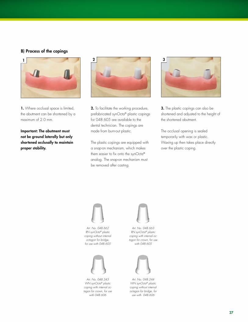
1. Where occlusal space is limited, the abutment can be shortened by a maximum of 2.0 mm.
Important: The abutment must not be ground laterally but only shortened occlusally to maintain proper stability.
2. To facilitate the working procedure, prefabricated synOcta® plastic copings for 048.605 are available to the dental technician. The copings are made from burn-out plastic.
The plastic copings are equipped with a snap-on mechanism, which makes them easier to fix onto the synOcta® analog. The snap-on mechanism must be removed after casting.
�. The plastic copings can also be shortened and adjusted to the height of the shortened abutment.
The occlusal opening is sealed temporarily with wax or plastic. Waxing up then takes place directly over the plastic coping.
Art. No. 048.662 RN synOcta® plastic
coping without internal octagon for bridge,
for use with 048.605
Art. No. 048.663 RN synOcta® plastic
coping with internal oc-tagon for crown, for use
with 048.605
Art. No. 048.243 WN synOcta® plastic coping with internal oc-tagon for crown, for use
with 048.606
Art. No. 048.244 WN synOcta® plastic coping without internal octagon for bridge, for
use with 048.606
B) Process of the copings
4 5
1 2 3
6
28
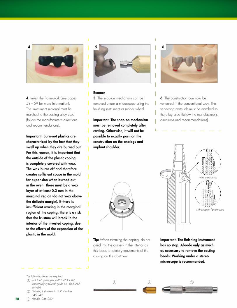
4. Invest the framework (see pages 58 – 59 for more information). The investment material must be matched to the casting alloy used (follow the manufacturer’s directions and recommendations).
Important: Burn-out plastics are characterized by the fact that they swell up when they are burned out. For this reason, it is important that the outside of the plastic coping is completely covered with wax. The wax burns off and therefore creates sufficient space in the mold for expansion when burned out in the oven. There must be a wax layer of at least 0.� mm in the marginal region (do not wax above the delicate margin). If there is insufficient waxing in the marginal region of the coping, there is a risk that the frustum will break in the interior of the invested coping, due to the effects of the expansion of the plastic in the mold.
The following items are required:1 synOcta® guide pin, 046.246 for RN
respectively synOcta® guide pin, 046.247 for WN
2 Finishing instrument for 45° shoulder, 046.243
3 Handle, 046.240
Reamer5. The snap-on mechanism can be removed under a microscope using the finishing instrument or rubber wheel.
Important: The snap-on mechanism must be removed completely after casting. Otherwise, it will not be possible to exactly position the construction on the analogs and implant shoulder.
Tip: When trimming the coping, do not grind into the corners in the interior as this leads to rotatory movements of the coping on the abutment.
6. The construction can now be veneered in the conventional way. The veneering materials must be matched to the alloy used (follow the manufacturer’s directions and recommendations).
Important: The finishing instrument has no stop. Abrade only as much as necessary to remove the casting beads. Working under a stereo microscope is recommended.
with snap-on lip
with snap-on lip removed
29
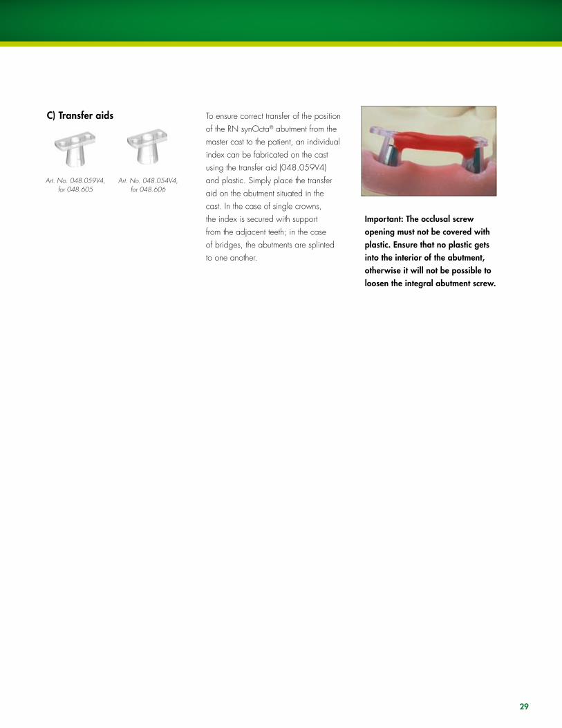
C) Transfer aids To ensure correct transfer of the position of the RN synOcta® abutment from the master cast to the patient, an individual index can be fabricated on the cast using the transfer aid (048.059V4) and plastic. Simply place the transfer aid on the abutment situated in the cast. In the case of single crowns, the index is secured with support from the adjacent teeth; in the case of bridges, the abutments are splinted to one another.
Important: The occlusal screw opening must not be covered with plastic. Ensure that no plastic gets into the interior of the abutment, otherwise it will not be possible to loosen the integral abutment screw.
Art. No. 048.059V4, for 048.605
Art. No. 048.054V4, for 048.606

�0
The restoration is delivered to the dentist with the original abutments on the master cast.
Remove the healing cap or temporary restoration. Thoroughly clean and dry the interior of the implants.
Remove the screws of the abutments from the master cast using a SCS screwdriver and place the transfer aid in the patient’s mouth. Transfer can be done using the screwdriver.
Important: Properly position the RN synOcta® abutments in the internal octagon. The abutment must first be properly positioned in the octagon of the implant before the screw is tightened.
Tighten the abutment screws with the SCS screwdriver along with the ratchet (046.119) and torque control device (046.049).
A tightening torque of �5 Ncm is recommended for inserting the abutments.
Tightening torque = �5 Ncm
See also CD-ROM “Straumann® Dental Implant System-Prosthetics,” USADV 022: Cemented single tooth restoration with the RN and WN synOcta® cemented abutment.
D) Fitting the final restoration

�1
10.C SyNOCTA® ANGlED FOR RN15° and 20° angled abutments for screw-retained and cement-retained crowns and bridges
RN angled abutments allow prosthetic restorations to be performed while equalizing the implant axis at the same time. The angles of 15° and 20° mean that the angle of insertion required for each situation can be determined and the necessary axis correction made. The angled abutment allows screw-retained and cement-retained crowns and bridges to be fabricated.
Important: RN angled abutments must not be used with 15° angled hollow cylinder implants.
Due to their design, long angled abutments may be shortened by a maximum of 2.0 mm, when shortened only cement-retained restorations can be done. Short angled abutments cannot be modified.
The RN synOcta® angled abutments are available in a short version (Art. No. 048.612/613/617/618) and a long version (Art. No. 048.610/611/615/616). The handling of both versions is identical. The difference in height is 1.0 mm.
15° 20°
22.5°
Selecting the correct abutment
Two types of RN synOcta® angled abutments are available for each angle, enabling the axis to be corrected in 16 different alignments (in 22.5° graduations).The use of the prosthetic planning kit (048.901) is recommended to help determine the most suitable abutment.
Art. No. 048.610, 048.61215°
Art. No. 048.615, 048.61720°
Art. No. 048.611, 048.61315°
Art. No. 048.616, 048.61820°
B = angle to the flat wallA = angle to the apex
Type BType A

1a 1b 2 �b�a
�2
1. Align the abutment on the working model and tighten the abutment screw using the SCS screwdriver.
Important: The abutment must be properly positioned in the octagon of the implant before the screw is tightened.
Tip: Once the correct position has been determined, it is recommended that the position on the model is marked with a felt-tip pen to ensure that the original position is immediately recognizable when the abutment is removed. During the modeling process, the lateral opening must be sealed with a material that can be easily removed (wax, gutta percha, modeling resin, silicone).
Important: This seal must be removed once the crown is completed.
2. Attach the plastic extension shell (048.670) to the abutment with a SCS occlusal screw and shorten occlusally or adapt individually. The screw head should always be out of occlusion in order to prevent any possible riveting of the screw head. The extension shell must always be used, since this contains the screw seating and is required for screw retention.
�. Model and cast the framework.The snap-on mechanism of the plastic shoulder must be removed after casting (for example, carefully with a polishing rubber under the microscope).Carry out veneering in accordance with the anatomical guidelines and allow for the premolarization in the lateral region. The “freedom in centric” concept should be used for the occlusion (see page 63).
Art. No. 048.676A-1) Fabricating a transocclusal screw-retained single crown
Option: Plastic shoulder for RN synOcta® 15° and 20° angled abutments
A special plastic shoulder with a snap-on mechanism (048.676V4) is available for modeling the framework. The modeling aid is made of a fully burn-out plastic. Simply put the shoulder on the shoulder of the analog until the snap-on mechanism clicks audibly into place. Modeling can be carried out in wax or plastic and can be used for transocclusal screw-retained and cement-retained crowns and bridges.

1
�a
2
�c�b
��
1. In this case, the occlusal opening must also be sealed (e.g., composite, gutta percha, silicone), in addition to the lateral opening.
�. Model and cast the framework. Carry out veneering in accordance with the anatomical guidelines and allow for premolarization in the lateral region.
The “freedom in centric” concept should be used for the occlusion (see page 63).
2. Position the plastic shoulder with snap-on mechanism (048.676V4), for RN synOcta® 15° and 20° angled abutments.
Important: Before delivery of the work to the dentist, the lateral seal of the screw opening must be removed to ensure that no residue is left, and the abutment must be cleaned.
A-2) Fabricating a cemented single crown

�4
To ensure correct transfer of the position of the RN synOcta® angled abutments from the master cast to the patient, the transfer aid can be used. It is made from polymerizable plastic.
It can be placed on Secure with thethe RN synOcta® SCS occlusal angled abutment. screw (048.350)
An index is fabricated using plastic. In the case of a bridge, the transfer aids can be splinted. Support from adjacent teeth is not required. If space is tight, the retention elements of the transfer aid can be shortened.
B) Transfer aids
Art. No. 048.002V4 for RN synOcta®
angled, long, Art. No. 048.610/
611/615/616
Art. No. 048.000V4 for RN synOcta®
angled, short, Art. No. 048.612/
613/617/618

�5
The restoration is delivered to the dentist with the original abutment on the master cast. loosen the abutment using the SCS screwdriver and remove it from the analog. Then, place the abutment in the patient’s mouth using the transfer aid. Finally, remove the transfer aid and fit the superstructure onto the implant.
Important: The RN synOcta® abutment is properly positioned in the internal octagon without the use of cement.
The abutment screw is tightened with the SCS screwdriver along with the ratchet (046.119) and torque control device (046.049).
Important: The abutment must be properly positioned in the octagon of the implant before the screw is tightened.
A tightening torque of �5 Ncm is recommended for inserting the abutments..
Tighten the crown with a torque of 15 Ncm using a SCS occlusal screw or a SCS guide screw shortened to occlusal level.
Important: If the superstructure is cemented, the lateral and the occlusal openings must be re-sealed with wax or gutta percha.
C) Fitting the final restoration
�6
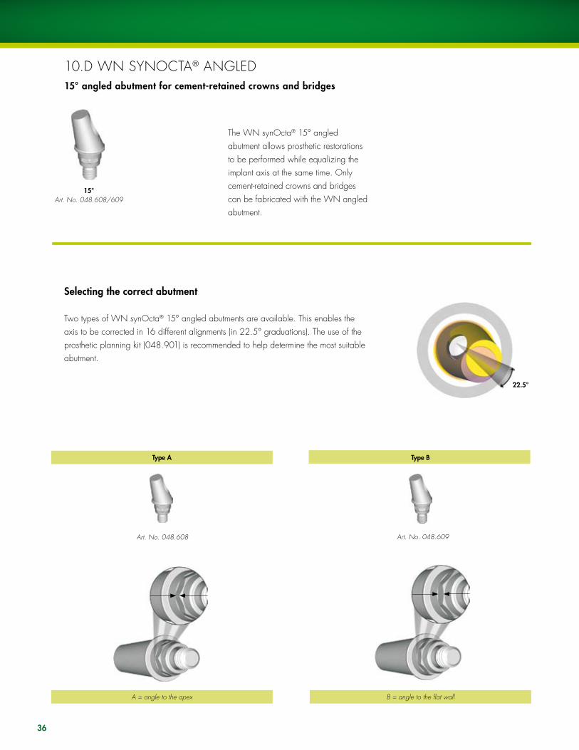
10.D WN SyNOCTA® ANGlED15° angled abutment for cement-retained crowns and bridges
The WN synOcta® 15° angled abutment allows prosthetic restorations to be performed while equalizing the implant axis at the same time. Only cement-retained crowns and bridges can be fabricated with the WN angled abutment.
15° Art. No. 048.608/609
22.5°
Selecting the correct abutment
Two types of WN synOcta® 15° angled abutments are available. This enables the axis to be corrected in 16 different alignments (in 22.5° graduations). The use of the prosthetic planning kit (048.901) is recommended to help determine the most suitable abutment.
Art. No. 048.608 Art. No. 048.609
B = angle to the flat wallA = angle to the apex
Type BType A

1 2
� 4b4a 5
�7
1. Align the abutment on the working model and tighten the abutment screw using the SCS screwdriver.
Important: The abutment must be properly positioned in the octagon of the implant before the screw is tightened.
Tip: Once the correct position has been determined, it is recommended that the position on the model is marked with a felt-tip pen in order to ensure that the original position is immediately recognizable when the abutment is removed.
2. During the modeling process, the lateral opening must be sealed with a material that can be easily removed (e.g., wax, gutta percha, modeling resin, silicone).
Important: This seal must be removed once the crown is completed.
Option: Plastic shoulder for WN synOcta® 15° angled abutmentThere is a special plastic shoulder with a snap-on mechanism (048.678) for modeling the framework. The modeling aid is made of a fully burn-out plastic.
Art. No. 048.678
�. Simply place the shoulder on the WN analog shoulder until the snap-on mechanism clicks audibly into place.
5. This is followed by casting of the framework. The snap-on mechanism of the plastic shoulder must be removed after casting (for example, carefully with a polishing rubber under the mi-croscope).
Important: Before delivery of the work to the dentist, the lateral seal of the screw opening must be removed, ensuring that no residue is left and the abutment is cleaned.
A) Fabricating a cement-retained single crown

�8
To ensure correct transfer of the position of the WN synOcta® angled abutment from the master cast to the patient, the transfer aid (048.032) can be used.It is made from polymerizable plastic.
The transfer aid is placed on the abutment.
Fabricate an index using plastic. In the case of a bridge, the transfer aids can be splinted. Support from adjacent teeth is not required. If space is tight, the retention elements of the transfer aid can be shortened.
Art. No. 048.032
B) Transfer aid

�9
C) Fitting the final restoration
The restoration is delivered to the dentist with the original abutment on the master cast. loosen the WN synOcta® angled abutment using the SCS screwdriver and remove from the analog. Place the abutment in the patient’s mouth using the transfer aid. Finally, remove the transfer aid and fit the superstructure.
Important: Properly position the abutment in the internal octagon without the use of cement.
Tighten the abutment screw with the SCS screwdriver along with the ratchet (046.119) and torque control device (046.049).
Important: The abutment must be properly positioned in the octagon of the implant before the screw is tightened.
A tightening torque of �5 Ncm is recommended for inserting the abutment.
Important: Before cementing the superstructure, the lateral opening must be resealed with wax or gutta percha.
Tightening torque = �5 Ncm

40
10.E RN SyNOCTA® TRANSVERSAlAbutment for transversal screw-retained crowns and bridges
Transversal screw retention is used in cases where occlusal/incisal screw retention is contraindicated due to reasons of esthetics and/or construction (axial alignment of the screw).Art. No. 048.620
Inserting of the abutmentPut the original abutment on the RN synOcta® analog and align in the octagon.
Important: The abutment must be properly positioned in the octagon before the screw is tightened.
The abutment screw is tightened by hand using the SCS screwdriver. The transversal opening can be aligned in 16 different positions.
A) Fabrication of the superstructure
One screw opening is aligned with the flat wall, while a second screw opening is aligned with the apex.
View from above
41
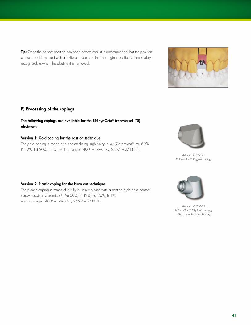
Tip: Once the correct position has been determined, it is recommended that the position on the model is marked with a felt-tip pen to ensure that the original position is immediately recognizable when the abutment is removed.
B) Processing of the copings
The following copings are available for the RN synOcta® transversal (TS) abutment:
Version 1: Gold coping for the cast-on techniqueThe gold coping is made of a non-oxidizing high-fusing alloy (Ceramicor®: Au 60 %, Pt 19 %, Pd 20 %, Ir 1%; melting range 1400° – 1490 °C, 2552° – 2714 °F).
Version 2: Plastic coping for the burn-out techniqueThe plastic coping is made of a fully burn-out plastic with a cast-on high gold content screw housing (Ceramicor®: Au 60 %, Pt 19 %, Pd 20 %, Ir 1%; melting range 1400° – 1490 °C, 2552° – 2714 °F).
Art. No. 048.634 RN synOcta® TS gold coping
Art. No. 048.665RN synOcta® TS plastic coping with cast-on threaded housing

1a
1b
2 �
42
1. Position the selected coping and then carefully tighten with a transversal screw (049.154) and the TS hexagonal screwdriver (046.420).
Important: The lingual/palatal part of the gold coping or the lingual/palatal edge of the threaded housing must not be modified prior to casting. Otherwise, the margin of the thread protection screw will no longer fit.
2. Wax up the framework in the conventional manner for veneers (plastic/porcelain). use the silicone key of the wax-up to check the framework shape.
The modeling is carried out on a scaled-down tooth shape. The crowns must be premolarized in size to reduce the risk of nonaxial loading and prevent plaque accumulation due to overcontouring.
Important: Do not cover the delicate margin of the copings with wax
�. When waxing up the framework, ensure that those areas of the pre-fabricated gold copings that are to be veneered with porcelain are coated with wax (at least 0.7 mm). As the gold coping consists of a non-oxidizing alloy, the porcelain cannot be bonded directly onto it (no oxidation for bonding).
4a
4b
5
4�
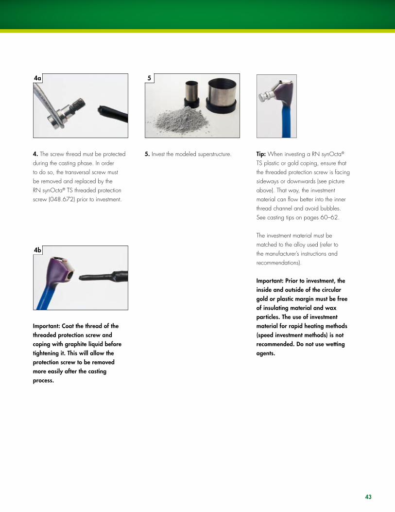
4. The screw thread must be protected during the casting phase. In order to do so, the transversal screw must be removed and replaced by the RN synOcta® TS threaded protection screw (048.672) prior to investment.
Important: Coat the thread of the threaded protection screw and coping with graphite liquid before tightening it. This will allow the protection screw to be removed more easily after the casting process.
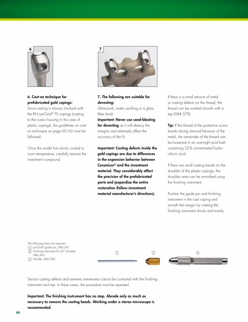
5. Invest the modeled superstructure. Tip: When investing a RN synOcta® TS plastic or gold coping, ensure that the threaded protection screw is facing sideways or downwards (see picture above). That way, the investment material can flow better into the inner thread channel and avoid bubbles. See casting tips on pages 60–62.
The investment material must be matched to the alloy used (refer to the manufacturer’s instructions and recommendations).
Important: Prior to investment, the inside and outside of the circular gold or plastic margin must be free of insulating material and wax particles. The use of investment material for rapid heating methods (speed investment methods) is not recommended. Do not use wetting agents.
6 7
1 2 3
44
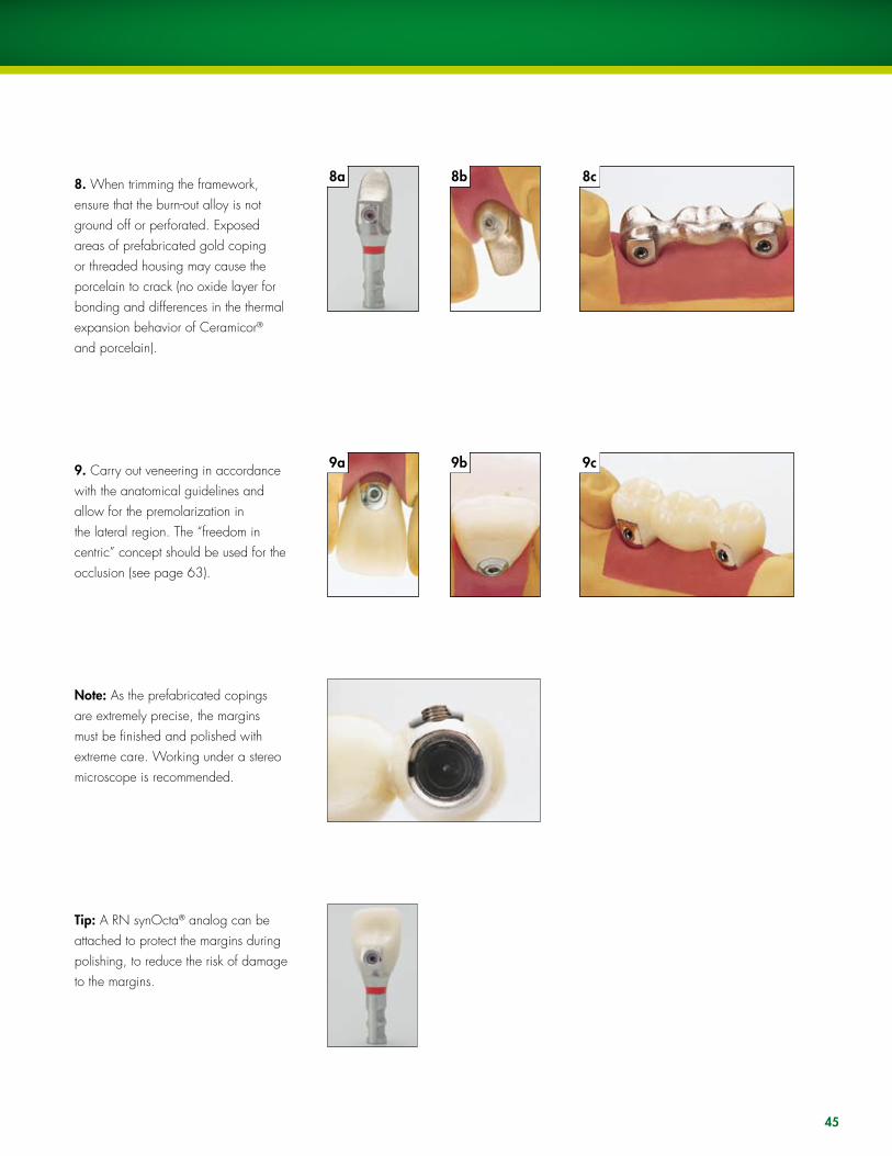
6. Cast-on technique for prefabricated gold copings:Since casting is always involved with the RN synOcta® TS copings (casting to the screw housing in the case of plastic copings), the guidelines on cast-on technique on page 60–62 must be followed.
Once the model has slowly cooled to room temperature, carefully remove the investment compound.
The following items are required:1 synOcta® guide pin, 046.2412 Finishing instrument for 45° shoulder,
046.2433 Handle, 046.240
7. The following are suitable for devesting:ultrasound, water, pickling or a glass fiber brush Important: Never use sand-blasting for devesting as it will destroy the margins and adversely affect the accuracy of the fit.
Important: Casting defects inside the gold copings are due to differences in the expansion behavior between Ceramicor® and the investment material. They considerably affect the precision of the prefabricated parts and jeopardize the entire restoration (follow investment material manufacturer’s directions).
If there is a small amount of metal or casting defects on the thread, the thread can be worked smooth with a tap (044.570).
Tip: If the thread of the protective screw breaks during removal because of the metal, the remainder of the thread can be loosened in an overnight acid bath containing 32 % concentrated hydro-chloric acid.
If there are small casting beads on the shoulder of the plastic copings, the shoulder area can be smoothed using the finishing instrument.
Position the guide pin and finishing instrument in the cast coping and smooth the margin by rotating the finishing instrument slowly and evenly.
Serious casting defects and extreme unevenness cannot be corrected with the finishing instrument and tap. In these cases, the procedure must be repeated.
Important: The finishing instrument has no stop. Abrade only as much as necessary to remove the casting beads. Working under a stereo microscope is recommended.
8b8a
9b9a
8c
9c
45
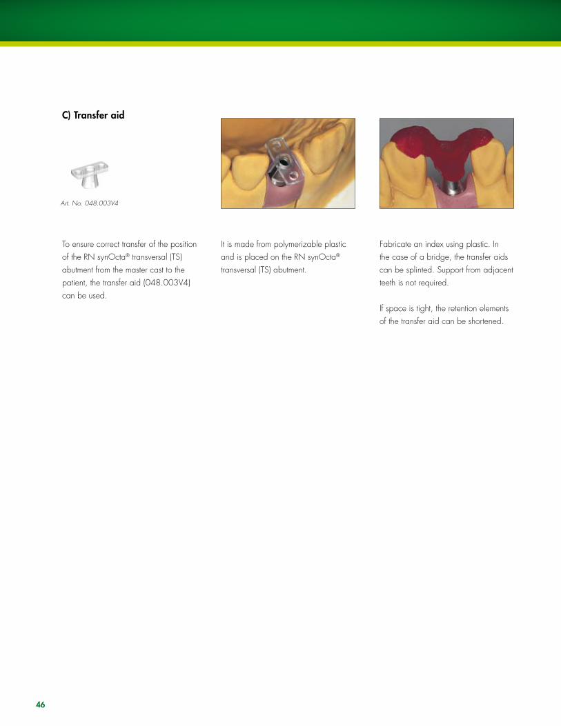
8. When trimming the framework, ensure that the burn-out alloy is not ground off or perforated. Exposed areas of prefabricated gold coping or threaded housing may cause the porcelain to crack (no oxide layer for bonding and differences in the thermal expansion behavior of Ceramicor® and porcelain).
9. Carry out veneering in accordance with the anatomical guidelines and allow for the premolarization in the lateral region. The “freedom in centric” concept should be used for the occlusion (see page 63).
Note: As the prefabricated copings are extremely precise, the margins must be finished and polished with extreme care. Working under a stereo microscope is recommended.
Tip: A RN synOcta® analog can be attached to protect the margins during polishing, to reduce the risk of damage to the margins.
46
C) Transfer aid
To ensure correct transfer of the position of the RN synOcta® transversal (TS) abutment from the master cast to the patient, the transfer aid (048.003V4) can be used.
It is made from polymerizable plastic and is placed on the RN synOcta® transversal (TS) abutment.
Fabricate an index using plastic. In the case of a bridge, the transfer aids can be splinted. Support from adjacent teeth is not required.
If space is tight, the retention elements of the transfer aid can be shortened.
Art. No. 048.003V4

47
The restoration is delivered to the dentist with the original abutment on the master cast.
Remove the healing cap or temporary restoration. Thoroughly clean and dry the interior of the implant.
Remove the RN synOcta® transversal (TS) abutment from the master cast using the SCS screwdriver.
Fit the abutment intraorally using the transfer aid.
Remove the transfer aid and fit the superstructure.
D) Fitting the final restoration
48
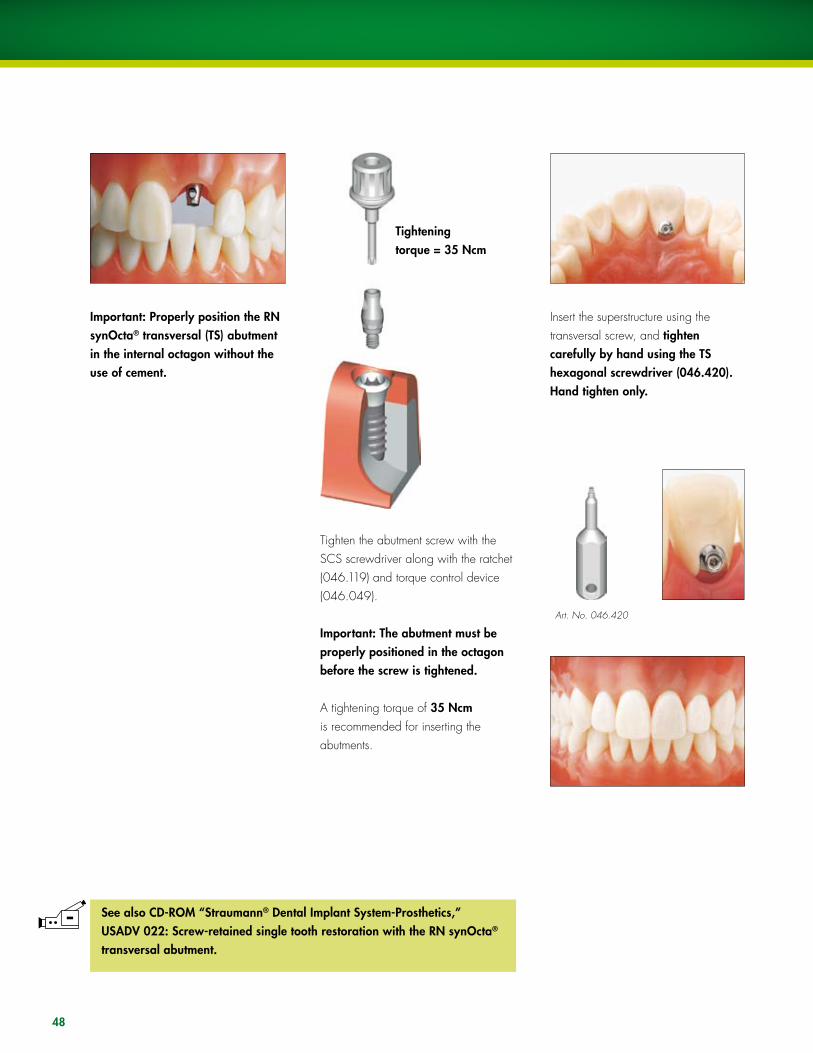
Important: Properly position the RN synOcta® transversal (TS) abutment in the internal octagon without the use of cement.
Tighten the abutment screw with the SCS screwdriver along with the ratchet (046.119) and torque control device (046.049).
Important: The abutment must be properly positioned in the octagon before the screw is tightened.
A tightening torque of �5 Ncm is recommended for inserting the abutments.
Insert the superstructure using the transversal screw, and tighten carefully by hand using the TS hexagonal screwdriver (046.420). Hand tighten only.
Tightening torque = �5 Ncm
Art. No. 046.420
See also CD-ROM “Straumann® Dental Implant System-Prosthetics,” USADV 022: Screw-retained single tooth restoration with the RN synOcta® transversal abutment.
49
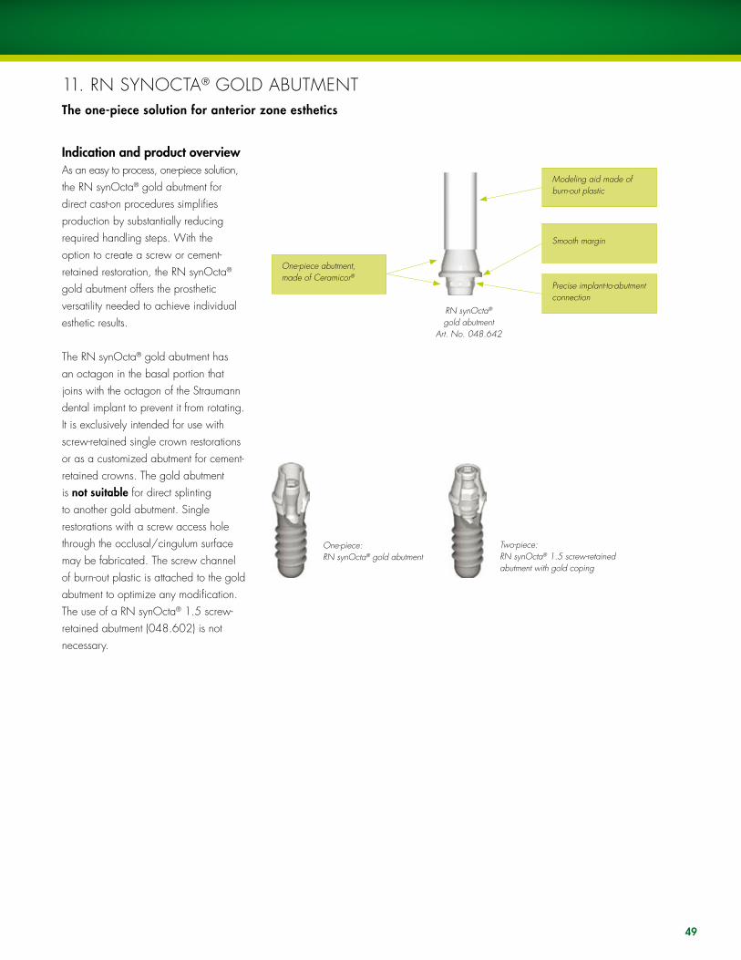
Indication and product overviewAs an easy to process, one-piece solution, the RN synOcta® gold abutment for direct cast-on procedures simplifies production by substantially reducing required handling steps. With the option to create a screw or cement-retained restoration, the RN synOcta® gold abutment offers the prosthetic versatility needed to achieve individual esthetic results.
The RN synOcta® gold abutment has an octagon in the basal portion that joins with the octagon of the Straumann dental implant to prevent it from rotating. It is exclusively intended for use with screw-retained single crown restorations or as a customized abutment for cement-retained crowns. The gold abutment is not suitable for direct splinting to another gold abutment. Single restorations with a screw access hole through the occlusal/cingulum surface may be fabricated. The screw channel of burn-out plastic is attached to the gold abutment to optimize any modification. The use of a RN synOcta® 1.5 screw-retained abutment (048.602) is not necessary.
RN synOcta® gold abutment
Art. No. 048.642
One-piece abutment, made of Ceramicor®
Modeling aid made of burn-out plastic
Smooth margin
Precise implant-to-abutmentconnection
11. RN SyNOCTA® GOlD ABuTMENTThe one-piece solution for anterior zone esthetics
One-piece: RN synOcta® gold abutment
Two-piece: RN synOcta® 1.5 screw-retained abutment with gold coping
1a 1b
50
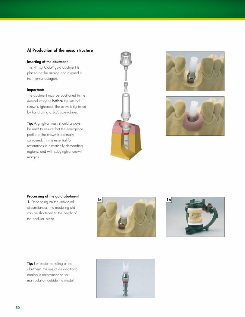
Inserting of the abutmentThe RN synOcta® gold abutment is placed on the analog and aligned in the internal octagon.
Important:The abutment must be positioned in the internal octagon before the internal screw is tightened. The screw is tightened by hand using a SCS screwdriver.
Tip: A gingival mask should always be used to ensure that the emergence profile of the crown is optimally contoured. This is essential for restorations in esthetically demanding regions, and with subgingival crown margins.
A) Production of the meso structure
Processing of the gold abutment1. Depending on the individual circumstances, the modeling aid can be shortened to the height of the occlusal plane.
Tip: For easier handling of the abutment, the use of an additional analog is recommended for manipulation outside the model.

2a
4a
2b
4b
�
4c
51
2. For optimal esthetic planning, a wax-up can be modeled.
�. A silicone key will be made over the wax-up to define the optimal wax modelation for the customized abutment.
4a. A wax modelation is contoured according to the anatomical circumstances of the individual case.
4b. The silicone key shows exactly the space for the cement-retained crown, which will be made over this customized abutment.
Note: The modeling on the abutment must be sufficiently thick (wax layer of at least 0.7 mm). Do not cover the delicate margin of the abutment with wax. The modeling aid ensures a clean and sharp-edged finish of the screw channel.
The picture shows an optimal design for fabrication of the customized abutment for contouring of an ideal emergence profile and adaptation of the margin to the gingival contour. Max. 2.0 mm
For reasons of hygiene, the cement margin must be no more than 2.0 mm below the gingival level.

5a
6a
5b
6b
52
5. Invest the customized abutment in the usual method without the use of wetting agents.
In order to avoid overflow of the cast-on alloy on the delicate circular edge and interior of the abutment, it is recommended to thoroughly clean the abutment prior to investment (removal of wax particles, insulating agents with a cotton pellet and/or brush moistened with alcohol).
Warning: Ensure that there is no wax on the delicate margin. The use of investment materials for rapid heating methods (speed investment materials) is not recommended. When processing the investment material, follow the investment material manufacturer’s instructions. Observe the recommended mixing ratio and preheating time exactly.
Tip: Always do the cast with the modeling aid. Otherwise the dental casting alloy will not, or only too thinly, flow out at the upper coping rim.
6. Cast the customized abutment. Gentle devestment with ultrasound, water jet, pickling acid or glass fiber brush
Note: Intruded casting metals and casting pearls cannot be removed from the shoulder part of the gold abutment with the reamer instrument for the 45° shoulder due to design reasons.
Warning: Never use sand-blasting for devestment, as it will destroy the abutment.
7a 7b
5�
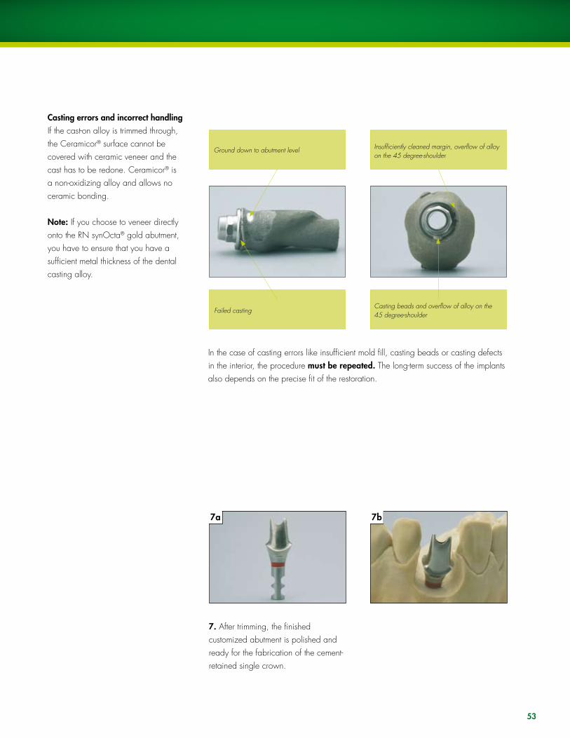
Casting errors and incorrect handlingIf the cast-on alloy is trimmed through, the Ceramicor® surface cannot be covered with ceramic veneer and the cast has to be redone. Ceramicor® is a non-oxidizing alloy and allows no ceramic bonding.
Note: If you choose to veneer directly onto the RN synOcta® gold abutment, you have to ensure that you have a sufficient metal thickness of the dental casting alloy.
In the case of casting errors like insufficient mold fill, casting beads or casting defects in the interior, the procedure must be repeated. The long-term success of the implants also depends on the precise fit of the restoration.
7. After trimming, the finished customized abutment is polished and ready for the fabrication of the cement-retained single crown.
Ground down to abutment level
Failed casting
Insufficiently cleaned margin, overflow of alloy on the 45 degree-shoulder
Casting beads and overflow of alloy on the 45 degree-shoulder
1a
�
5
1b
4b4a
6b6a
2
4c
54
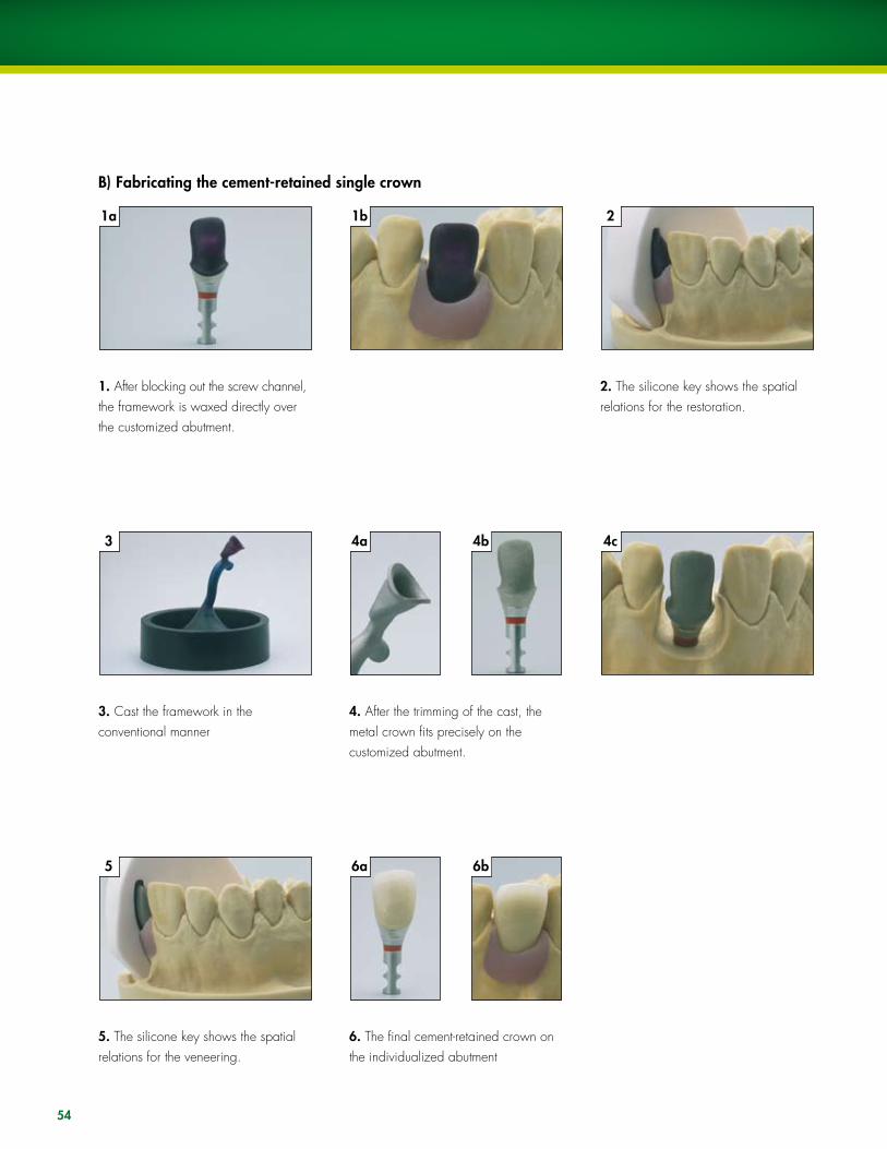
1. After blocking out the screw channel, the framework is waxed directly over the customized abutment.
2. The silicone key shows the spatial relations for the restoration.
�. Cast the framework in the conventional manner
4. After the trimming of the cast, the metal crown fits precisely on the customized abutment.
5. The silicone key shows the spatial relations for the veneering.
6. The final cement-retained crown on the individualized abutment
B) Fabricating the cement-retained single crown

55
The restoration is delivered to the dentist with the customized abutment on the master cast. The customized abutment must be positioned in the internal octagon of the implant without the use of cement. The basal screw of the RN synOcta® gold abutment is then tightened to �5 Ncm on the implant using a SCS screwdriver, ratchet (046.119) and torque control device (046.049).
Before cementing the crown, the SCS configuration of the occlusal screw should be closed with cotton and sealing compound (gutta percha). This allows the possibility of later removal of the customized abutment in case a crown replacement becomes necessary.
The final restoration will be definitively cemented on the customized abutment.
Tightening torque = �5 Ncm
See also CD-ROM “Straumann® Dental Implant System-Prosthetics,” USADV 022: Screw-retained single tooth restoration with the RN synOcta® gold abutment.
C) Fitting the final restoration

1
1. Any case with more than 3.0 mm of soft tissue would be a potential site for use of the synOcta® Meso abutment.
2
2. Create a diagnostic wax up or setup. �. Make a lab putty index that will record the neutral zone of the edentulous space. This will provide a visual guide for the modification of the synOcta® Meso abutment.
4. Remove the tissue from the model, seat the abutment on the master case, and contour.
5. Remove the abutment from the master cast and replace the tissue. Return the abutment to the master cast, and mark the tissue height with a marker.
6. Note the proposed extended finish line that the abutment will be reduced to.
7
7. using end cutting titanium carbide, complete the final preparations. Polish the modified abutment using rubber and silicone.
8
8. Return the abutment to the master cast, and verify the preparations with the lab index.
9
9. This lateral view illustrates that the abutment has been properly modified to allow enough room for the final restoration.
MESO ABuTMENT STEP-By-STEP
�a �b
4 5 6
Proposed finish line
56
10
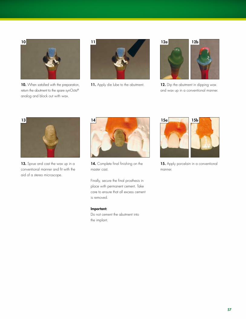
10. When satisfied with the preparation, return the abutment to the spare synOcta® analog and block out with wax.
11
11. Apply die lube to the abutment.
12a
12. Dip the abutment in dipping wax and wax up in a conventional manner.
1�
1�. Sprue and cast the wax up in a conventional manner and fit with the aid of a stereo microscope.
14
14. Complete final finishing on the master cast.
Finally, secure the final prosthesis in place with permanent cement. Take care to ensure that all excess cement is removed.
Important:Do not cement the abutment into the implant.
15. Apply porcelain in a conventional manner.
12b
15a 15b
57

12. PROCESSING INSTRuCTIONSInvesting and casting
Casting tips for burn-out plastic copings
For implant shoulder Ø 4.8 mm RN
Casting the frameworkThe success of work carried out with prefabricated plastic components depends onthe attention paid to the following points:
ß Burn-out plastics are characterized by the fact that they swell up when they are burned out. For that reason it is important that the outside of the plastic coping is completely covered with wax. The wax burns off and therefore creates sufficient space in the mold for expansion when burned out in the oven. There must be a wax layer of at least 0.3 mm in the marginal region (Caution: Do not wax above the delicate margin). If there is insufficient waxing in the marginal region of the coping, there is a risk that the frustum will break in the interior of the invested coping (screw channel), due to the effects of the expansion of the plastic in the mold.
ß To avoid casting errors due to wax particles, insulating agents, etc., careful cleaning of the interior and the inside and outside of the delicate edge of the coping prior to investment (e.g., with a cotton bud soaked in alcohol) is recommended.
ß The sprues must encourage elimination of the wax and plastic and must not impede the direction of flow of the alloy (i.e., there should be no sharp angles and edges). Follow the investment material manufacturer’s recommendations on the selection and positioning of sprues.
For implant shoulder Ø 6.5 mm WN
58
ß Do not use wax wetting agents, if possible. The plastic is so smooth that the investment material will fill all the fine contours of the coping’s interior very well during investment (with the aid of a fine blunt instrument or a fine brush). However, if wetting agents are utilized, ensure that no aggressive wetting agents are used which could attack the surface of the plastic copings. Then blow-dry the copings carefully with compressed air. Wetting agent residues can lead to a reaction with the investing material and thus to casting errors.
ß To avoid air bubbles or casting beads in the case of occlusal screw-retained plastic copings, ensure that the investment material flows through the screw channel into the interior of the coping. If it flows directly into the interior, this can lead to the formation of bubbles.
ß The use of phosphate-bonded investment materials that allow a staged burn-out is recommended. These must be matched with the alloy used.
ß When processing the investment material, follow the investment material manufacturer’s instructions. Observe the recommended mixing ratio and preheating times exactly.
ß The use of investment material for rapid heating methods (speed investment methods) is not recommended.
ß use only high gold content alloys, and refer to the alloy manufacturer’s alloy tables.
59

60
Casting tips for prefabricated gold copings (Ceramicor®)
For implant shoulder Ø 4.8 mm RN
Casting the frameworkß Do not use wax wetting agents, if possible. The fine film of the wax wetting agent
on the surface of the gold during casting can result in metal on the 45° shoulder or in the interior (also see casting tips for burn-out plastics, page 58–59). In this case, the work has to be repeated, as the long-term success of the implants also depends on the accurate fit of the prosthetic work.
ß In order to avoid overflow of the cast-on alloy on the delicate circular edge and interior of the gold/plastic copings, it is advisable to clean them prior to investment (removal of wax particles, insulating agents, for instance, with a cotton bud soaked in alcohol).
ß The sprues must encourage elimination of the wax and plastic and must not impede the direction of flow of the alloy (i.e., there should be no sharp angles and edges). Follow the investment material manufacturer’s recommendations on the selection and positioning of the sprues.
ß The use of phosphate-bonded investment materials is recommended. These must be matched to the alloy used.
ß When processing the investment material, follow the investment material manufacturer’s instructions. Observe the recommended mixing ratio and preheating times exactly.
ß The use of investment materials for rapid heating methods (speed investment materials) is not recommended.
For implant shoulder Ø 6.5 mm WN
61
Guidelines for creating reliable cast-on joints
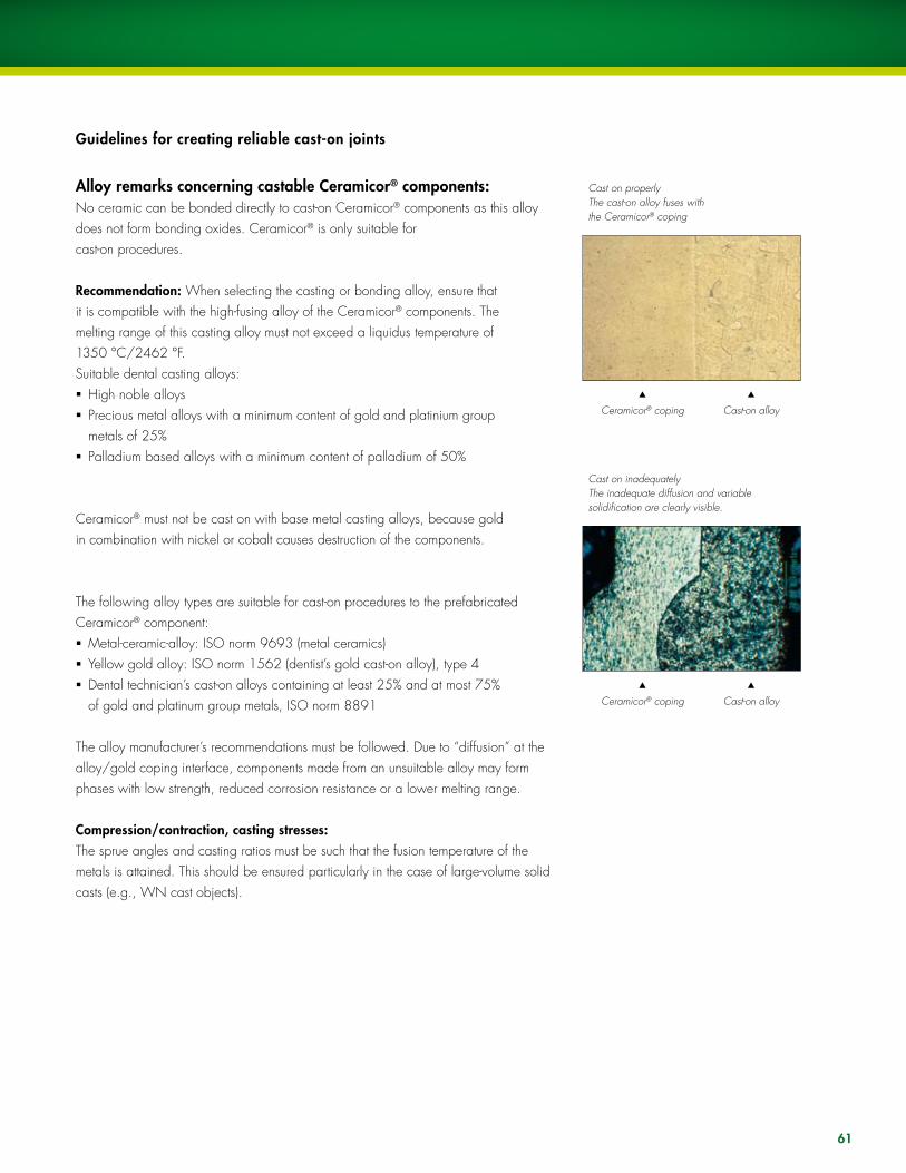
Cast on properlyThe cast-on alloy fuses with the Ceramicor® coping
Ceramicor® coping Cast-on alloy
Cast on inadequatelyThe inadequate diffusion and variable solidification are clearly visible.
Ceramicor® coping Cast-on alloy
Alloy remarks concerning castable Ceramicor® components:No ceramic can be bonded directly to cast-on Ceramicor® components as this alloy does not form bonding oxides. Ceramicor® is only suitable for cast-on procedures.
Recommendation: When selecting the casting or bonding alloy, ensure that it is compatible with the high-fusing alloy of the Ceramicor® components. The melting range of this casting alloy must not exceed a liquidus temperature of 1350 °C/2462 °F.Suitable dental casting alloys:ß High noble alloysß Precious metal alloys with a minimum content of gold and platinium group
metals of 25%ß Palladium based alloys with a minimum content of palladium of 50%
Ceramicor® must not be cast on with base metal casting alloys, because gold in combination with nickel or cobalt causes destruction of the components.
The following alloy types are suitable for cast-on procedures to the prefabricated Ceramicor® component:ß Metal-ceramic-alloy: ISO norm 9693 (metal ceramics)ß yellow gold alloy: ISO norm 1562 (dentist’s gold cast-on alloy), type 4ß Dental technician’s cast-on alloys containing at least 25% and at most 75%
of gold and platinum group metals, ISO norm 8891
The alloy manufacturer’s recommendations must be followed. Due to “diffusion” at the alloy/gold coping interface, components made from an unsuitable alloy may form phases with low strength, reduced corrosion resistance or a lower melting range.
Compression/contraction, casting stresses: The sprue angles and casting ratios must be such that the fusion temperature of the metals is attained. This should be ensured particularly in the case of large-volume solid casts (e.g., WN cast objects).
62
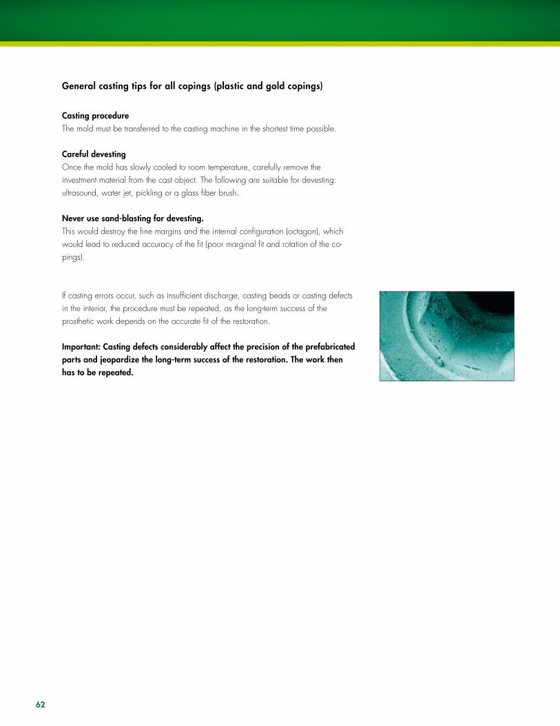
General casting tips for all copings (plastic and gold copings)
Casting procedureThe mold must be transferred to the casting machine in the shortest time possible.
Careful devestingOnce the mold has slowly cooled to room temperature, carefully remove the investment material from the cast object. The following are suitable for devesting: ultrasound, water jet, pickling or a glass fiber brush.
Never use sand-blasting for devesting.This would destroy the fine margins and the internal configuration (octagon), which would lead to reduced accuracy of the fit (poor marginal fit and rotation of the co-pings).
If casting errors occur, such as insufficient discharge, casting beads or casting defects in the interior, the procedure must be repeated, as the long-term success of the prosthetic work depends on the accurate fit of the restoration.
Important: Casting defects considerably affect the precision of the prefabricated parts and jeopardize the long-term success of the restoration. The work then has to be repeated.
6�
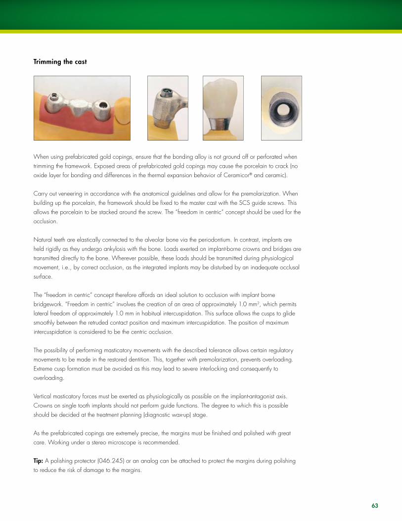
Trimming the cast
When using prefabricated gold copings, ensure that the bonding alloy is not ground off or perforated when trimming the framework. Exposed areas of prefabricated gold copings may cause the porcelain to crack (no oxide layer for bonding and differences in the thermal expansion behavior of Ceramicor® and ceramic).
Carry out veneering in accordance with the anatomical guidelines and allow for the premolarization. When building up the porcelain, the framework should be fixed to the master cast with the SCS guide screws. This allows the porcelain to be stacked around the screw. The “freedom in centric” concept should be used for the occlusion.
Natural teeth are elastically connected to the alveolar bone via the periodontium. In contrast, implants are held rigidly as they undergo ankylosis with the bone. loads exerted on implant-borne crowns and bridges are transmitted directly to the bone. Wherever possible, these loads should be transmitted during physiological movement, i.e., by correct occlusion, as the integrated implants may be disturbed by an inadequate occlusal surface.
The “freedom in centric” concept therefore affords an ideal solution to occlusion with implant borne bridgework. “Freedom in centric” involves the creation of an area of approximately 1.0 mm2, which permits lateral freedom of approximately 1.0 mm in habitual intercuspidation. This surface allows the cusps to glide smoothly between the retruded contact position and maximum intercuspidation. The position of maximum intercuspidation is considered to be the centric occlusion.
The possibility of performing masticatory movements with the described tolerance allows certain regulatory movements to be made in the restored dentition. This, together with premolarization, prevents overloading. Extreme cusp formation must be avoided as this may lead to severe interlocking and consequently to overloading.
Vertical masticatory forces must be exerted as physiologically as possible on the implant-antagonist axis. Crowns on single tooth implants should not perform guide functions. The degree to which this is possible should be decided at the treatment planning (diagnostic wax-up) stage.
As the prefabricated copings are extremely precise, the margins must be finished and polished with great care. Working under a stereo microscope is recommended.
Tip: A polishing protector (046.245) or an analog can be attached to protect the margins during polishing to reduce the risk of damage to the margins.

64
Alloy Ceramicor®
Color White
Composition AuPtPdAgCuIrother
%%%%%%
+ = <1%
60.019.020.0
1.0
Melting range ºC 1400º –1490 ºC ºF 2552º –2714 ºF
Heat expansion coefficient
WAK
ºC 25–500 ºC = 11.9 μm/m x ºC 25–600 ºC = 12.2 μm/m x ºC ºF 77–932 ºF = 11.9 μm/m x ºF 77–1112 ºF = 12.2 μm/m x ºF
Hardness condition (by delivery) HV5 220
Hardness after casting or soldering HV5 205Self-hardening
Hardened HV5 205
0,2 % proof stress (Rp 0,2 %) condition as delivered
N/mm2 780
0,2 % proof stress (Rp 0,2 %) after castingor soldering
N/mm2
635
Possibilities for metal bonding Casting or soldering
Technical informationApplications
Non-oxidizing alloy for casting-on with precious metal alloys or for soldering with precious metal and non-precious metal alloys.
Material information
65
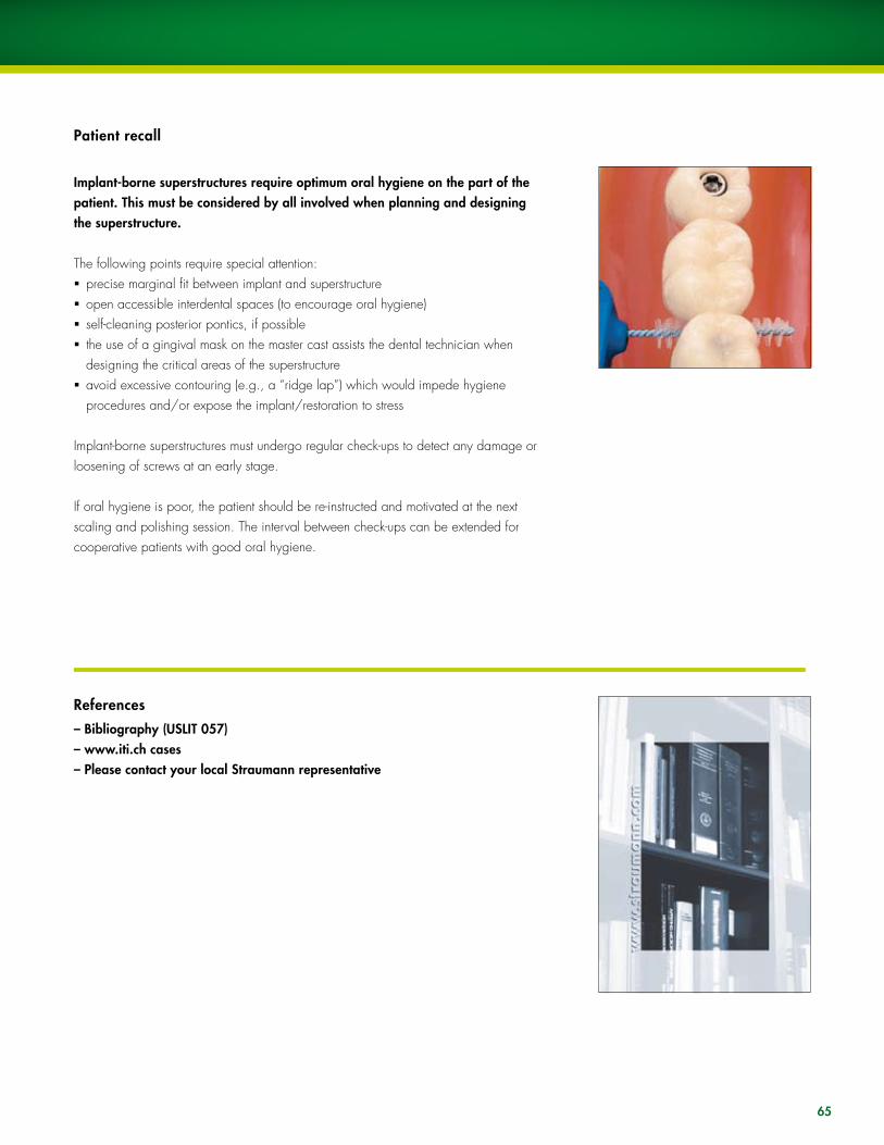
Patient recall
Implant-borne superstructures require optimum oral hygiene on the part of the patient. This must be considered by all involved when planning and designing the superstructure.
The following points require special attention:ß precise marginal fit between implant and superstructureß open accessible interdental spaces (to encourage oral hygiene)ß self-cleaning posterior pontics, if possibleß the use of a gingival mask on the master cast assists the dental technician when
designing the critical areas of the superstructureß avoid excessive contouring (e.g., a “ridge lap”) which would impede hygiene
procedures and/or expose the implant/restoration to stress
Implant-borne superstructures must undergo regular check-ups to detect any damage or loosening of screws at an early stage.
If oral hygiene is poor, the patient should be re-instructed and motivated at the next scaling and polishing session. The interval between check-ups can be extended for cooperative patients with good oral hygiene.
References
– Bibliography (USLIT 057)– www.iti.ch cases– Please contact your local Straumann representative
66
Documentation
On the “Straumann® Dental Implant System-Prosthetics“ CD-ROM, uSADV 022, you will find the following films on the following subjects:
Screw-retained single tooth restoration with the RN synOcta® 1.5 screw-retained abutment.
Cemented single tooth restoration with the RN and WN synOcta® cemented abutment.
Cemented single tooth restoration with the WN synOcta® Cemented abutment.
Screw-retained single tooth restoration with the RN synOcta® transversal abutment.
Screw-retained single tooth restoration with the RN synOcta® gold abutment.
Cemented single tooth restoration with the angled NN Titanium abutment.
Single tooth restoration on a RN Solid abutment.
Single tooth restoration on a WN Solid abutment.
Hybrid dentures: Screw-retained bar construction on RN synOcta® 1.5 screw-retained abutment.
67
Disclaimer of liabilityThe Straumann® dental implant is part of an overall concept and may only be used in conjunction with the associated original components and instruments according to Institut Straumann AG’s instructions and recommendations. use of products made by third parties in conjunction with the Straumann® Dental Implant System will void any warranty or other obligation, expressed or implied, of Straumann. Instruction as to application of our products takes place verbally, in writing, by electro-nic media, or in hands-on training corresponding to state-of-the-art at the time of introduction of the product. The user of Straumann products has the duty to determine whether or not any product is suitable for a particular patient and circumstance. Straumann disclaims any liability, expressed or implied, and shall have no responsibility for any direct, indirect, punitive or other damages, arising out of, or in connection, with any errors in professional judgment or practice in the use or installation of Straumann products.
The user is also obliged to study the latest developments of the Straumann® Dental Implant System and its applications regularly.
Please noteThe descriptions given are insufficient to allow immediate use of the Straumann® Dental Implant System. Guidance in the handling of these instruments by a doctor experienced in their use is strongly recommended.
Validityupon publication of this brochure, all previous versions are superseded.
AvailabilityNot all products listed in this brochure are available in all countries.
CautionOur products must be secured against aspiration when used intraorally (e.g., use of a throat pack is recommended).
Federal law restricts these devices to sale by, or on the order of, a dentist or physician.
Units per packageunless stated otherwise, there is one unit in each package.
Documentationyou can obtain detailed instructions on the Straumann® Dental Implant System from your Straumann representative.
DefinitionSlA® = Sand-blasted, large grit, Acid-etched
SlActiveTM = Sand-blasted, large grit, Acid-etched, chemically active and hydrophilic.
Copyright and trademarksStraumann documents may not be reprinted or published, in whole or part, without the written authorization of Institut Straumann AG. Straumann® Dental Implant System, SlA®, and synOcta® are registered trademarks of Institut Straumann AG, Switzerland.
Explanation of the symbols on labels and instruction leaflets
lot/batch number
Article number
Sterile by gamma irradiation
Non-sterile
upper temperature limit
Temperature limitation
Caution: Federal (uSA) law restricts these devices to sale by, or on the order of, a dentist or physician
Do not use on patients
Do not reuse
Refer to instructions for use
use before expiration date
Protect from exposure to strong light or heat
Straumann products carry the CE mark and fulfill the requirements of the Medical Devices Directive 93/42 EEC
Colored warning labels YELLOW ➡ Caution: Indicates hazards or unsafe handling that might cause minor injury or damage to property.
ORANGE ➡ Warning: Indicates hazards that might cause serious or fatal injury.
RED ➡ Danger: Indicates hazards that might cause immediate serious or fatal injury.
lOT
REF
RSTER I lE
IMPORTANT NOTES
STER I lE
Stra
uman
n pr
oduc
ts ar
e C
E m
arke
d
8/
07
C
AlIT
187
International HeadquartersInstitut Straumann AG Peter Merian-Weg 12CH-4002 Basel, SwitzerlandPhone +41 (0)61 965 11 11Fax +41 (0)61 965 11 01
www.s t raumann.com
North American DistributorsStraumann uSA, llC 60 Minuteman Road Andover, MA 01810 Phone 800/448 8168 978/747 2500 Fax 978/747 2490 www.straumannusa.com
Straumann Canada limited 4145 North Service Road, Suite 303Burlington, ON l7l 6A3 Phone 800/363 4024 905/319 2900 Fax 905/319 2911 www.straumann.ca


