
JUNE 2018, ATHENS
NATIONAL TECHNICAL UNIVERSITY OF ATHENS
NAVAL ARCHITECTURE AND MARINE ENGINEERING
LABORATORY OF SHIPBUILDING TECHNOLOGY
Cryogenic Treatment of
Uddeholm Orvar 2M tool steel
Diploma Thesis
Anthi I. Tsaroucha
SUPERVISOR: DIMITRIOS I. PANTELIS
COMMITTEE: DIMITRIOS E. MANOLAKOS
DIMITRIOS I. PANTELIS
NIKOLAOS G. TSOUVALIS

1

2
Preface
This thesis is written in order to examine the effects of the cryogenic treatment on the
mechanical properties and microstructure of Uddeholm Orvar 2M tool steel. It has been written
to fulfill the graduation requirements of the Naval Architecture and Marine Engineering studies
at the National Technical University of Athens (NTUA). I was engaged in researching and
writing this diploma thesis from March 2017 to June 2018.
I would like to thank my professor, Dr. Dimitrios I. Pantelis, for the assignment of this project,
for his supervision on the subject as well as his valuable advises during the process. Moreover, I
would like to thank Dr. Chara Sarafoglou and Mr Dimitrios Papageorgiou for their guidance and
their assistance during the experimental procedure. Additionally, I would like to thank Thodoris
Langos and the staff of the laboratory of the Mechanical Engineers field for their assistance
during experimental procedure. Many thanks to Prof. Nikolaos G. Tsouvalis and Prof. Dimitrios
E. Manolakos for their participation as the examination committee. Last but not least, many
thanks to my family and my friends Antonia, Vasiliki, Dimitrios, Elena, Polina, Simos,
Dimitrios, Christina for their support and their patience through this study.
Anthi Tsaroucha Greece, 2018

3
Abstract
The purpose of this study procedure is to examine the effect of Cryogenic Treatment on the
microstructure and mechanical properties, especially microhardness, of hot work H13 tool steel.
The thesis is divided in two parts – theoretical and experimental. During the first chapter of the
study, reference regarding the steels is made, focusing on tool steels category, especially H13 hot
work tool steel. The second chapter contains an overview of the heat treatment procedures,
which are carried out on steels, paying attention on the processes applied on tool steels. The last
theoretical part refers to Cryogenic treatment with a presentation of the parameters and factors
affecting the treatment and a study of the results on microstructure and mechanical properties of
tool steels through years of experiments.
The experimental part concerns a research regarding the effect of cryogenic treatment as an
addition to conventional treatment on Uddeholm Orvar 2M tool steel microstructure and
microhardness. In case of our study, Uddeholm Orvar 2M tool steel is going to be subjected to
cryogenic treatment with subsequent tempering. The experimental procedure consists of two
heat treatment cycles, focusing on the impact of cryogenic temperature and soaking time on the
material. The tool steel specimens are going to be under austenitization quenching, cryogenic
treatment and tempering at different temperatures (TT). All the processes are going to be carried
out in the above sequence. Regarding subzero procedure, the first cycle consists of the
conventional treatment with an addition of deep cryogenic process at -195 oC for 24 hrs. The
second cycle differs on the conditions, including a cryogenic treatment at -130 oC for 20 minutes.
By using a microscope and a scanning electron microscope (SEM), the grain boundaries, the
retained austenite, as well as the primary and secondary carbides are going to be observed.
Moreover, the measurement of the microhardness for every TT will form a distribution, from
which, conclusions about the conditions of primary and secondary hardness will be extracted.
The experiment of the study showed that the subzero treatment contributes to increase of
hardness, decrease of retained austenite and homogenous distribution of finer carbides.
4
Contents
Chapter I: Tool Steels ................................................................................................................................. 6
Section 1: Introduction .................................................................................................................................. 6
1.1 General Information - Steels ............................................................................................................... 6
1.2 Classification of Steels ........................................................................................................................ 6
Section 2: Tool steels .................................................................................................................................... 8
2.1 General Information ............................................................................................................................ 8
2.2 Applications ........................................................................................................................................ 8
2.3 Classification and Characteristics ....................................................................................................... 9
2.4 Hot Work steels ................................................................................................................................. 10
2.4.1 Chromium hot-work steels (types H10 to H19) ........................................................................ 10
2.4.2 Tool Steel H13 ........................................................................................................................... 10
Chapter II: Heat Treatment in Tool Steels ............................................................................................ 14
Section 1: Introduction ................................................................................................................................ 14
1.1 Heat Treatment Processes for steels ................................................................................................. 14
1.2 Annealing .......................................................................................................................................... 14
1.3 Austenitization .................................................................................................................................. 16
1.4 Quenching ......................................................................................................................................... 16
1.5 Tempering ........................................................................................................................................ 19
Section 2: Structural transformation methods ............................................................................................ 20
2.1 Diffusion ........................................................................................................................................... 20
2.2 Martensite Transformation ............................................................................................................... 20
2.3 Stages of Hardening .......................................................................................................................... 21
Section 3: Tool steels .................................................................................................................................. 22
3.1 Austenitization ................................................................................................................................. 22
3.2 Quenching ........................................................................................................................................ 23
3.3 Tempering ........................................................................................................................................ 23
3.4 Cryogenic treatment of Steels .......................................................................................................... 24
3.5 Cryogenic Treatment on Tool Steels ................................................................................................ 25
Chapter III: Cryogenic Treatment .......................................................................................................... 26
5
Section 1: Introduction ................................................................................................................................ 26
Section 2: Microstructure ............................................................................................................................ 27
2.1 Retained Austenite ............................................................................................................................ 27
2.2 Carbide precipitation ......................................................................................................................... 36
Section 3: Hardness and Fracture Toughness ............................................................................................. 46
3 Cryogenic treatment in different stages and in combination with surface treatments ........................... 51
Chapter IV – Experimental Procedure ................................................................................................... 60
Section 1: Introduction ................................................................................................................................ 60
1.2 Specimens’ preparation ..................................................................................................................... 60
1.3 Pre Treatment .................................................................................................................................... 62
1.3.1 Stage No 1: Austenitization ....................................................................................................... 62
1.3.2 Stage No2: Quenching ............................................................................................................... 65
1.3.3 Stage No3: Cryogenic Treatment ............................................................................................... 67
1.3.4 Stage No4: Tempering ............................................................................................................... 70
1.4 After Treatment ............................................................................................................................... 72
1.4.1 Cutting ........................................................................................................................................ 72
1.4.2 Mounting .................................................................................................................................... 73
1.4.3 Grinding and Polishing .............................................................................................................. 74
Section 2: Results ........................................................................................................................................ 76
2.1 Microstructure ................................................................................................................................... 76
2.2 Carbide Precipitation ........................................................................................................................ 80
2.3 Hardness ............................................................................................................................................ 88
Conclusion ................................................................................................................................................. 93
ANNEX I .................................................................................................................................................... 94
ANNEX II ................................................................................................................................................ 105
References ................................................................................................................................................ 115

6
Chapter I: Tool Steels
Section 1: Introduction
1.1 General Information - Steels
Steels can be manufactured relatively inexpensively in large quantities to very precise
specifications. That is the reason they are the most widely used category of metallic material
They are characterized by a wide range of mechanical properties, from moderate yield strength
levels (200 to 300 MPa, or 30 to 40 ksi) with great ductility to yield strengths exceeding 1400
MPa (200 ksi) with fracture toughness levels as high as 110 MPa (100 ksi). [1]
Steel's base metal is iron is able to take on two crystalline forms (allotropic forms), body
centered cubic (BCC) and face centered cubic (FCC), depending on its temperature. The
interaction of those allotropes with the alloying elements, primarily carbon gives steel and cast
iron their range of unique properties. In the body-centered cubic arrangement, there is an iron
atom in the center of each cube, and in the face-centered cubic, there is one at the center of each
of the six faces of the cube. [20]
1.2 Classification of Steels[1]
Steels can be classified by a variety of different systems depending on:
• The composition, such as carbon, low-alloy, or stainless steels
• The manufacturing methods, such as open hearth, basic oxygen process, or electric
furnace methods
• The finishing method, such as hot rolling or cold rolling
• The product form, such as bar, plate, sheet, strip, tubing, or structural shape
• The deoxidation practice, such as killed, semi killed, capped, or rimmed steel
• The microstructure, such as ferritic, pearlitic, and martensitic (Fig. 1)
• The required strength level, as specified in ASTM standards
• The heat treatment, such as annealing, quenching and tempering, and thermo-mechanical
processing
• Quality descriptors, such as forging quality and commercial quality

7
Fig.1 Classification based on microstructure for steels
8
Section 2: Tool steels
2.1 General Information
Tool steels are used to make tools for cutting, forming, or shaping a material into a part or
component adapted to a definite use. Before 1868, tool steels were simple, plain carbon steels,
but in the early 20th century, many complex, highly alloyed tool steels were developed. These
alloy tool steels, which contain relatively large amounts of tungsten, molybdenum, vanadium,
manganese, and chromium, were able to meet increasingly severe service demands and provide
much better dimensional control and freedom from cracking during heat treatment. Many alloy
tool steels are also widely used for machinery components and structural applications in which
particularly stringent demands are to be faced, such as high-temperature springs, ultrahigh
strength fasteners, special-purpose valves, and bearings of various types for elevated-temperature
service. [2]
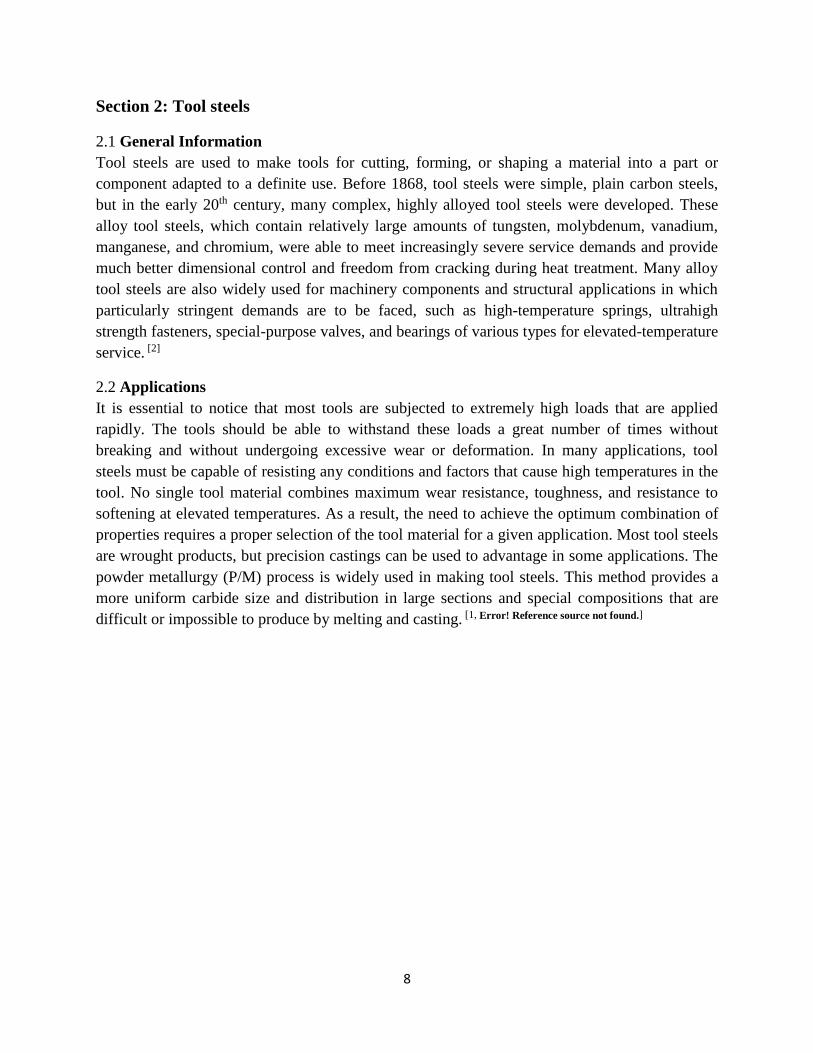
2.2 Applications
It is essential to notice that most tools are subjected to extremely high loads that are applied
rapidly. The tools should be able to withstand these loads a great number of times without
breaking and without undergoing excessive wear or deformation. In many applications, tool
steels must be capable of resisting any conditions and factors that cause high temperatures in the
tool. No single tool material combines maximum wear resistance, toughness, and resistance to
softening at elevated temperatures. As a result, the need to achieve the optimum combination of
properties requires a proper selection of the tool material for a given application. Most tool steels
are wrought products, but precision castings can be used to advantage in some applications. The
powder metallurgy (P/M) process is widely used in making tool steels. This method provides a
more uniform carbide size and distribution in large sections and special compositions that are
difficult or impossible to produce by melting and casting. [1, Error! Reference source not found.]

9
2.3 Classification and Characteristics
The very large number of tool steels is effectively classified by the widely used system
developed by the American Iron and Steel Institute (AISI). This system is the starting point for
the selection of the proper steel for a given function from the large number of steels available.
The AISI classification system arranges tool steels into groups that are based on prominent
characteristics such as: [Error! Reference source not found.]
• Alloying (for example, tungsten or molybdenum high-speed steels),
• Application (for example, cold-work or hot-work tool steels),
• Heat treatment (for example, water-hardening or oil hardening tool steels).
Table 1 lists nine main groups of tool steels and their identifying letter symbols
Table 1 Main groups of tool steels and AISI letter symbols
Group Identifying Symbol
Water-hardening tool steels W
Shock-resisting tool steels S
Oil-hardening cold-work tool steels O
Air-hardening, medium-alloy cold-work tool
steels A
High-carbon, high-chromium cold-work tool
steels D
Mold steels P
Hot-work tool steels, chromium, tungsten, and
molybdenum H
Tungsten high-speed tool steels T
Molybdenum high-speed tool steels M
Several very general alloying and heat treatment principles are introduced at this point to provide
a base for comparing the various groups of tool steels:
• The hardened microstructure of a typical tool steel consists of a matrix of tempered
martensite containing various dispersions of iron and alloy carbides.
• High carbon and high alloy content promote hardenability or the ability to form
martensite on cooling.
• The higher the carbon and alloy content in supersaturation in the martensite, as inherited
from the parent austenite, the higher the density of carbides that can be formed on
tempering.
• The higher the content of strong carbide-forming elements, the higher the density of
stable carbides in austenite during hot work and austenitizing. These carbides are retained
as components of the microstructure in addition to those formed in martensite during
tempering.
10
• The higher the carbon content of the martensite and the higher the density of carbides, the
higher the hardness and wear resistance but the lower the toughness of a tool steel
microstructure.
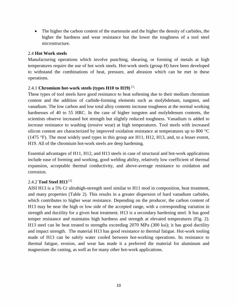
2.4 Hot Work steels
Manufacturing operations which involve punching, shearing, or forming of metals at high
temperatures require the use of hot work steels. Hot-work steels (group H) have been developed
to withstand the combinations of heat, pressure, and abrasion which can be met in these
operations.
2.4.1 Chromium hot-work steels (types H10 to H19) [1]
These types of tool steels have good resistance to heat softening due to their medium chromium
content and the addition of carbide-forming elements such as molybdenum, tungsten, and
vanadium. The low carbon and low total alloy contents increase toughness at the normal working
hardnesses of 40 to 55 HRC. In the case of higher tungsten and molybdenum contents, the
scientists observe increased hot strength but slightly reduced toughness. Vanadium is added to
increase resistance to washing (erosive wear) at high temperatures. Tool steels with increased
silicon content are characterized by improved oxidation resistance at temperatures up to 800 °C
(1475 °F). The most widely used types in this group are H11, H12, H13, and, to a lesser extent,
H19. All of the chromium hot-work steels are deep hardening.
Essential advantages of H11, H12, and H13 steels in case of structural and hot-work applications
include ease of forming and working, good welding ability, relatively low coefficient of thermal
expansion, acceptable thermal conductivity, and above-average resistance to oxidation and
corrosion.
2.4.2 Tool Steel H13 [1]
AISI H13 is a 5% Cr ultrahigh-strength steel similar to H11 mod in composition, heat treatment,
and many properties (Table 2). This results in a greater dispersion of hard vanadium carbides,
which contributes to higher wear resistance. Depending on the producer, the carbon content of
H13 may be near the high or low side of the accepted range, with a corresponding variation in
strength and ductility for a given heat treatment. H13 is a secondary hardening steel. It has good
temper resistance and maintains high hardness and strength at elevated temperatures (Fig. 2).
H13 steel can be heat treated to strengths exceeding 2070 MPa (300 ksi); it has good ductility
and impact strength. The material H13 has good resistance to thermal fatigue. Hot-work tooling
made of H13 can be safely water cooled between hot-working operations. Its resistance to
thermal fatigue, erosion, and wear has made it a preferred die material for aluminum and
magnesium die casting, as well as for many other hot-work applications.

11
However, H13 is subject to hydrogen embrittlement. It can be nitride for additional wear
resistance. Although H13 has not been used as widely as H11 mod as an ultrahigh-strength
constructional steel, the similarities in properties make H13 equally attractive for such
applications. This is particularly true in noncritical service in which slightly higher wear
resistance is an advantage.
Fig. 2 IT diagram for H13 steel containing 0.40% C, 1.05% Si, 5.00% Cr, 1.35% Mo, and 1.10% V. Courtesy of
Crucible Steel Co.
Properties
Table 2 Compositions of H13 steel
Medium-alloy air-
hardening steels
Composition, wt %
C Mn Si Cr Mo V
H13 0.32−0.45 0.20−0.50 0.80−1.20 4.75−5.50 1.10−1.75 0.80−1.20
Somewhat different properties should be expected when the carbon content is near either the
high end or the low end of the range.

12
H13 tool steel is one of the most widely used of all hot-work tool steels. Although the steel is
well known, costly tool failures, which happen, can be lead to the insufficient knowledge of heat
treatment. The hardening temperature lies between 1000°C and 1050°C. The temperature for the
hardening operation is chosen in order for the material to obtain the properties that are regarded
as the most important ones. The strength at elevated temperatures increases as the hardening
temperature is raised but this increase in strength takes place at the expense of the toughness.
The higher the hardening temperature the more susceptible is the steel to grain growth. Coarse-
grained steel is less tough than a fine-grained one.
Due to high vanadium content, grade H13 is not unduly susceptible to grain growth. It is
essential to notice that the grain size number after hardening should be at least 7 ASTM. In the
case of a neutral salt bath heating treatment the holding time is easily kept under control. If the
tool is pack-heated, it is difficult to confirm the actual holding time and therefore when this
method of heating is used the lower temperature of the hardening range is recommended.
As the hardening temperature increases, the greater the number of carbides go into solution. For
grade H 13 this leads to the fact that the higher the hardening temperature the sooner is the start
of the carbide precipitation that precedes the pearlite and bainite formation when quenching the
steel. [25]
Fig. 3 Influence of hardening temperature and holding time on
grain size of steel H 13

13
Impact strength determinations carried out on specimens of steel H13, after having been
hardened from various temperatures, show that toughness decreases with increasing hardening
temperature (Fig.3). In this case, grain growth cannot have been the only factor that must be in
concern since the steel is relatively insensitive to grain growth. Tests involving different rates of
cooling have shown that the lowest cooling rate resulted in the lowest impact strength. It has also
been demonstrated that there is a connection between low impact values and the presence of
precipitated grain-boundary carbides in the steel. Hence, if the highest possible impact strength is
to be imparted to grade H13, a moderately high hardening temperature combined with a high
cooling rate should be used. [25]
Applications [16]
Typical applications for the specific grade H13 include casting dies for aluminium, magnesium
and zinc, extrusion dies for aluminium and brass, liners, mandrels, pressure pads, followers,
bolsters, die cases, die holders and adaptor rings for copper and brass extrusion. H13 can be used
in production of hot stamping and press forge dies, split hot heading dies, gripper dies, hot
punching, piercing and trimming tools. Other applications consist of plastic moulds, shear blades
for hot work and hot swaging dies and also tooling and structural applications including punches,
shafts, beams, torsion bars, shrouds, and ratchets.

14
Chapter II: Heat Treatment in Tool Steels
Section 1: Introduction
1.1 Heat Treatment Processes for steels [41]
As it has been discussed, most of the steels, in order to be used in production and industry,
should be subjected to heat treatment in order to have their mechanical and physical properties
improved. Heat treatments processes are used to provide the demanded properties for the last
stage of the steels before production.
Heat treatment processes include two categories, a) heat treatment inside the matrix and b)
treatment on the surface of steels.
Heat treatment of steel
• Annealing
• Austenitization
• Quenching
• Tempering
Heat treatment processes are designed with the purpose of increasing steel hardness, decreasing
or total elimination of mechanical stresses and regulating the grain size and the properties.
1.2 Annealing[2]
Steels are submitted to a wide range of annealing processes for improvement of their mechanical
and other properties. Annealing is a generic term denoting a treatment that consists of heating
and holding at a suitable temperature followed by cooling at an appropriate rate, primarily for the
softening of metallic materials. In plain carbon steels, annealing produces a ferrite-pearlite
microstructure. Steels can be annealed in order to facilitate cold working or machining, to
improve mechanical and electrical properties, or in the case of achieving dimensional stability.

15
Fig.4 Iron-carbon binary phase diagram
The critical temperatures that must be considered in the annealing process of steel are those that
define the onset and completion of the transformation to or from austenite (Fig 4). The critical
temperatures depend on whether the steel is being heated or cooled. Critical temperatures for the
start and completion of the transformation to austenite during heating are denoted, respectively,
by Ac1 and Ac3 for hypoeutectoid steels and by Ac1 and Accm for hypereutectoid steels. These
temperatures are higher than the corresponding critical temperatures for the start and completion
of the transformation from austenite during cooling, which are denoted, respectively, by Ar3 and
Ar1 for hypoeutectoid steels and by Arcm and Ar1 for hypereutectoid steels. (The "c" and "r" in
the symbols are derived from the French words chauffage for heating and refroidissement for
cooling.) These critical temperatures converge to the equilibrium values Ae1, Ae3, and Aecm as
the rates of heating or cooling become infinitely slow. Various alloying elements markedly affect
these critical temperatures. For example, chromium raises the eutectoid temperature, A1, and
manganese lowers it.

16
1.3 Austenitization[41]
Austenitization includes heating steel on a temperature almost 50 oC above upper critical
temperature (Ac3). In order to achieve complete austenitization, steel remains in these
temperature conditions for a certain amount of time, to obtain homogeneous austenite without
undissolved carbides. The time of austenitization is important since too much extending of
duration may cause overheating and eventually unwanted increased grain size.
During heating, a difference in temperature between the surface and inner mass of the alloy is
observed. As a result, plastic deformation of the crystalline mesh in the austenitic area is caused.
Therefore, it is essential for the process to be carried out on a relatively slow rate. As
temperature increases until austenitization, steel is oxidized, causing material loss from the
surface and decreasing its content in carbon. The above problems can easily be treated by heating
in furnaces of controlled atmosphere conditions.
1.4 Quenching[2]
Quenching is the process of rapidly cooling metal parts from the austenitizing or solution treating
temperature, typically from within the range of 815 to 870 °C (1500 to 1600 °F) for steel.
Stainless and high-alloy steels usually are submitted to quenching to minimize the presence of
grain boundary carbides or to improve the ferrite distribution. However, most steels including
carbon, low-alloy, and tool steels, are quenched in order to produce controlled amounts of
martensite in the microstructure. Successful hardening means achieving the required
microstructure, hardness, strength, or toughness while minimizing residual stress, distortion, and
the possibility of cracking.
The selection of a quenchant medium depends on the hardenability of the particular alloy, the
section thickness and shape involved, and the cooling rates needed to achieve the desired
microstructure. The most common quenchant media are either liquids or gases. The liquid
quenchants commonly used include:
• Oil that may contain a variety of additives
• Water
• Aqueous polymer solutions
• Water that may contain salt or caustic additives
The most widely used gaseous quenchants are inert gases including helium, argon, and nitrogen.
These quenchants are sometimes used after austenitizing in a vacuum. The ability of a quenchant
to harden steel depends on the cooling characteristics of the quenching medium. Quenching
effectiveness is dependent on the steel composition, type of quenchant, or the quenchant use
conditions. The success of the procedure is also based on the design of the quenching system and
the thoroughness with which the system is maintained.

17
In conclusion, the objective of the quenching process is cooling steel from the austenitizing
temperature sufficiently quickly to form the desired microstructural phases, sometimes bainite
but more often martensite. The basic quenchant function is to control the rate of heat transfer
from the surface of the part being quenched.
Quenching Process
The rate of heat extraction by a quenching medium and the way it is used substantially affects
quenchant performance (Fig. 5). Variations in quenching practices have resulted in the
assignment of specific names to some quenching techniques:
• Direct quenching
• Time quenching
• Selective quenching
• Spray quenching
• Fog quenching
• Interrupted quenching
Direct quenching refers to quenching directly from the austenitizing temperature and is by far
the most widely used practice. The term direct quenching is used to differentiate this type of
cycle from more indirect practices which might involve carburizing, slow cooling, reheating,
followed by quenching.

18
Fig. 5 Comparison of cooling rates and temperature gradients as work pieces pass into and through martensite
transformation range for a conventional quenching and tempering process and for interrupted quenching processes.
(a) Conventional quenching and tempering processes that use oil, water, or polymer quenchants. (b) Marquenching,
which uses either salt or hot oil as a quenchant. (c) Austempering, which uses a salt as a quenchant. (d) Isothermal
quenching, which uses either salt or hot oil as a quenchant.

19
1.5 Tempering [2]
Tempering of steel refers to the process in which previously hardened or normalized steel is
usually heated to a temperature below the lower critical temperature and cooled at a suitable rate,
primarily to increase ductility and toughness, but also to increase the grain size of the matrix.
Steels are tempered by reheating after hardening to obtain specific values of mechanical
properties and also to relieve quenching stresses and to ensure dimensional stability. Tempering
usually follows quenching from above the upper critical temperature. However, tempering is also
used to relieve the stresses and reduce the hardness developed during welding and to relieve
stresses induced by forming and machining.
Principal Variables
Variables associated with tempering that affect the microstructure and the mechanical properties
of tempered steel include:
• Tempering temperature
• Time at temperature
• Cooling rate from the tempering temperature
• Composition of the steel, including carbon content, alloy content, and residual elements
In the case of quenched steel which is characterized by a microstructure consisting essentially of
martensite, the iron lattice is strained by the carbon atoms, producing high hardness. Upon
heating, the carbon atoms diffuse and react in a series of distinct steps that eventually form Fe3C
or alloy carbide in a ferrite matrix of gradually decreasing stress level. The properties of the
tempered steel are primarily determined by the size, shape, composition, and distribution of the
carbides that form, with a relatively minor contribution from solid-solution hardening of the
ferrite. These changes in microstructure usually decrease hardness, tensile strength, and yield
strength but increase ductility and toughness.
Under certain conditions, hardness may remain unaffected by tempering or may even be
increased as a result of it. For instance, tempered steel at very low tempering temperatures may
cause no change in hardness but may produce a desired increase in yield strength. Moreover,
those alloy steels that contain one or more of the carbide-forming elements (chromium,
molybdenum, vanadium, and tungsten) can achieve secondary hardening and increase hardness
after tempering.
Temperature and time are interdependent variables in the tempering process. Lowering
temperature, within limits, and increasing time can usually produce the same effect as raising
temperature and decreasing time. However, minor temperature changes have a far greater effect
than minor time changes in typical tempering operations. With few exceptions, tempering is
carried out at temperatures between 175 and 705 °C (350 and 1300 °F) and for times from 30
min to 4 h.

20
Section 2: Structural transformation methods [41]
The study of structural transformations for metals and alloys depends on the knowledge of the
balance curves. In order to learn about metallurgical characteristics of alloys, it is essential to
study two types of curves.
• Solidification Curves
• Solid State Transformation Curves
For this section, we study the second category of curves mentioned, in which heat treatment
processes are based on. Two basic structural transformation methods that are observed, during
heat treatment, are diffusion and martensite transformation.
2.1 Diffusion [41]
Diffusion is the process of migration of individual atoms within materials and takes place in
gases, liquids and solids, and consequently occurs in steels and other metallic systems. Diffusion
is of immense importance to most heat treatment processes and therefore some appreciation of
the mechanisms and laws of diffusion will facilitate the understanding of many heat treatments
including carburizing and decarburizing, nitriding and annealing. [25]
The atoms move due to the phenomenon of diffusion, which is caused from the temperature
difference between neighboring positions. Their transposition is great (of magnitude 1-106 of
interatomic distance) and they jump in random positions. Transformation rate depends abruptly
on heating temperature. For example, diffusion happens in lower rate for temperature 525 oC
than in 700 oC. It is extremely important to mention that the phenomenon of diffusion cannot be
carried out at temperatures below 0.3-0.4Tm. The total volume of the transformed material also
depends on heating temperature and time. In conclusion, diffusion allows the change in chemical
composition of different phases in alloys. Furthermore, there is a chance that crystallographic
relationship between initial and final structure may occur in the process.
2.2 Martensite Transformation [41]
Martensite transformation is happening during quenching, below the temperature MS (start of
martensite transformation), creating instantaneously a new phase called martensite. The
martensite phase is formed as soon as the temperature is reached and the phenomenon does not
continue in isothermal conditions. Therefore, in order to keep creating the new phase, the
temperature must decrease and as a result martensite keeps forming in new areas instead of
continuing from the already formed positions. For steels, martensite is formed, since cooling rate
is fast enough to prevent pearlitic phase from being generated through mechanism of diffusion.
The atoms move in small distances (magnitude of interatomic distance) creating and breaking
interatomic bonds and they transpose consecutively in exact sequence.

21
Transformation rate equals to the rate of the mesh vibrations in the crystal. On the contrary, it is
not related to temperature and the transformation is able to happen even on temperature near 4K.
The total volume of the transformed material is related only to temperature. The temperature
regarding the start of martensite transformation MS as well as the temperature related to the end
of formation Mf decreases as content in carbon increases. The critical quenching rate (VC)
changes according to content in carbon and depends on grain size and clarity of steel.
Chemical composition remains unchanged and the atoms, as they do not have the necessary time
to move, they stay at their positions. Moreover, there is always crystallographic relationship
between the generated martensite phase and the initial mesh.
Heat treatment of steel, especially martensitic hardening is usually accompanied by the evolution
of large residual stresses, which exist without any external load on the part considered. Causes
for such stresses include:
• Thermal expansion or contraction of a homogeneous material in a temperature gradient
field
• Different thermal expansion coefficients of the various phases in a multiphase material
• Density changes due to phase transformations in the metal
• Growth stresses of reaction products formed on the surface or as precipitates, for
example, external and internal oxidation
2.3 Stages of Hardening
It is essential to know that complete transformation from austenite to martensite is generally
preferable prior to tempering. However, conditions vary widely, and 100% transformation
rarely, occurs. During hardening, martensite develops as a continuous process from start (MS) to
finish (Mf) through the martensite formation range. Except in a few highly alloyed steels,
martensite starts to form at well above room temperature. In many cases, transformation is
essentially complete at room temperature. Retained austenite tends to be present in varying
amounts. However, for some applications, this retained austenite must be transformed to
martensite and then tempered.
The below stages describe the procedure of hardening steels.
a) Austenitization
b) Quenching
c) Tempering
22
Section 3: Tool steels
With few exceptions, all tool steels must be heat treated to develop specific combinations of
wear resistance, resistance to deformation or breaking under high loads, and resistance to
softening at elevated temperatures. A few simple shapes may be obtained directly from tool steel
producers in correctly heat-treated condition. However, most tool steels first are formed or
machined to produce the required shape and then heat treated as required.
Improper finishing after heat treatment and most important grinding can damage tool steels
through the development of surface residual stresses and cracks. Some tools are heat treated in a
blank or semi-finished state and subsequently ground, turned, or electrical discharge machined to
create the final tool. Even though the above manufacturing techniques have progressed in recent
years, metallurgical damage and surface stresses are still a major worriment.
Annealing [2]
Tool steels are usually received from the supplier in the annealed condition in order to be easily
machined and heat treated. However, if they are subjected to hot or cold forming, often they
must be fully annealed again before subsequent operations. Whether a tool is to be submitted to
rehardening, it should first be thoroughly annealed. This procedure is important with the steels of
higher alloy content to avoid irregular grain growth occurs and a mixed grain size (sometimes
called fish scale or duplex grains). All of the chromium hot-work steels have high hardenability.
3.1 Austenitization [2]
Austenitizing is the most critical of all heating operations performed on tool steels. Tools that are
subjected to excessively high austenitizing temperatures or abnormally long holding times may
produce excessive distortion, abnormal grain growth, loss of ductility, and low strength. This
problem can be faced in the case of high-speed steels, which are frequently austenitized at a
temperature close to that at which melting begins. Moreover, underheating may result in low
hardness and low wear resistance. During the process of quenching, if the center of a tool is
cooler than the exterior, spalling or fracturing of the corners may result, particularly with water-
hardening steels. Prior to heat treatment, all tool surfaces must be free of decarburization.
During austenitization the final alloy element partitioning between the austenitic matrix (that will
transform to martensite) and the retained carbides occurs. This partitioning fixes the chemistry,
volume fraction, and dispersion of the retained carbides. The retained alloy carbides contribute to
wear resistance, and control austenitic grain size. The finer the carbides and the larger the
volume fraction of carbides, the more effectively austenitic grain growth is controlled. Thus if
austenitizing is performed at too high a temperature, undesirable grain growth may occur inside
the material as the alloy carbides increasingly coarsen or dissolve into the austenite.

23
3.2 Quenching [2]
Quenching from the austenitizing temperature may be carried out in water, brine, oil, salt, inert
gas, or air, depending on composition and section thickness. The quenching medium must cool
the work piece rapidly enough to obtain full hardness. The selection of the cooling medium is
important since mediums which exceed the requirements may cause cracking or excessive
distortion may occur.
Tool steels that will harden during air cooling are frequently hot quenched to the range 540 to
650 °C (1000 to 1200 °F) after austenitizing. Quenching time is long enough for decomposition
of austenite to begin. After hot quenching, the steels are air cooled or oil quenched to ambient
temperature. Hot quenching minimizes distortion without adversely affecting hardness since it
prevents the hard scale from forming on most air-hardening steels during air cooling.
3.3 Tempering [2]
Tempering produces a more desirable combination of strength, hardness, and toughness than
obtained in the quenched steel. The quenched structure of tool steel is a heterogeneous mixture
of retained austenite, untempered martensite, and carbides. The changes that take place in the
microstructure during tempering of hardened tool steels are time-temperature dependent. Time at
tempering temperature should not be less than 1 h for any given cycle.
Most manufacturers of high-speed steels recommend multiple tempers of 2 h or more each to
attain the desired microstructure and properties. Carrying out the procedure with recommended
tempering times, temperatures, and number of tempers (a minimum of two) ensures attainment
of consistent tempered martensitic structures and overcomes uncertainties caused by variations in
the amount of retained austenite in the quenched condition. These variances are based on
differences in heat chemistry, prior thermal history, hardening temperatures, and quenching
conditions. Other factors that influence the tempering requirements of high-speed steels are:
• Increasing the free (matrix) carbon content increases the amount of retained austenite in
the as-quenched condition
• The amount of retained austenite significantly affects the rate of transformation,
particularly for short tempering cycles. Multiple tempering is more important to attain an
acceptable structure if short tempering times are used
• Cobalt in alloys such as M42 reduces the amount of retained austenite in the as-quenched
condition and accelerates the transformation of the retained austenite during tempering
24
3.4 Cryogenic treatment of Steels [4]
Cryogenics is usually defined as the science and technology dealing with temperatures less than
about 120 K. The techniques which are used to produce cryogenic temperatures are significantly
different from those dealing with conventional refrigeration. One major point of difference is the
need to precool the compressed gas before it is expanded in order to reach cryogenic
temperatures when starting from 0 ◦C or higher. Precooling can be accomplished with a cascade
of refrigerant baths or with a heat exchanger. The value of cryogenic treatment of steel and other
materials has been debated for many years; even today many metallurgical professionals have
serious reservations about its value.
Several theories exist in order to understand the reasons behind the use and evolvement of
cryogenic treatment. One theory involves the more nearly complete transformation of retained
austenite into martensite. This theory has been verified by x-ray diffraction measurements.
Another theory is based on the strengthening of the material caused by precipitation of
submicroscopic carbides as a result of the cryogenic treatment. Allied with this is the reduction
in internal stresses in the martensite that happens when the submicroscopic carbide precipitation
occurs. A reduction in micro cracking tendencies resulting from reduced internal stresses is also
suggested as a reason for improved properties.
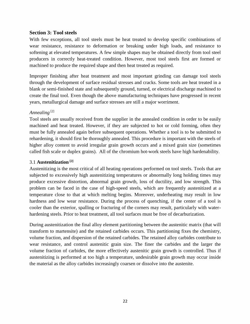
Cryogenic Treatment Cycles [2]
Typical cryogenic treatment consists of a slow cool-down (~2.5 °C/min, or 4.5 °F/min) from
ambient temperature to liquid nitrogen temperature. When the material reaches approximately 80
K (-315 °F), it is soaked for an appropriate time (generally 24 h). At the end of the soak period,
the material is removed from the liquid nitrogen and allowed to warm to room temperature in
ambient air. The temperature-time plot for this cryogenic treatment is shown in Fig.6. By
conducting the cool-down cycle in gaseous nitrogen, temperature can be controlled accurately
and thermal shock to the material is avoided. Single-cycle tempering is usually performed after
cryogenic treatment to improve impact resistance, although double or triple tempering cycles are
sometimes used.
Fig. 6 Plot of temperature versus time for the cryogenic treatment process

25
Equipment for Cryogenic Treatment [2]
Liquid nitrogen systems have become the customary method for achieving cryogenic
temperatures. The two types of systems are described below.
• The heat-exchanger system passes liquid nitrogen through a heat exchanger, and the
exhaust gas from the unit is piped into the main gaseous-nitrogen header line. The
chamber atmosphere is drawn over the heat-exchanger coils by a fan. In some versions of
the system, the cooling is boosted by spraying liquid nitrogen directly into the chamber.
• The direct spray system sprays liquid nitrogen directly into the chamber, while a fan
circulates the gases over the work. In this system, the spent gas cannot be recovered for
use as a furnace atmosphere. The equipment design does not permit the liquid nitrogen to
come into direct contact with the work, thereby reducing the probability of thermal
shock.
In both systems, temperature controllers are used to control the flow of liquid nitrogen (through a
solenoid valve) and to monitor the work temperature. Temperature charts of the cycle provide a
record of the processing.
3.5 Cryogenic Treatment on Tool Steels
The complete treatment process in case of steels consists of Hardening (Austenitization +
Quenching), CT, and Tempering. CT is an expanded process to conventional heat-treatment
process (Hardening and Tempering). It has experimentally discovered that the CT, when carried
out after quenching and prior to tempering, contributes to activation of the tempering
transformations of the virgin martensite because of its high oversaturation attained at -196 oC (77
K). Due to this, the carbide precipitation occurs with higher activation energy, thus leading to a
higher nucleation rate and, in turn, to finer dimensions and a more homogeneous distribution.
Depending upon the application of the temperature it may be classified as
• Cold treatment, which is also recognized as Shallow Cryogenic Treatment (SCT), is to
gradually cool the work piece in the range -84 oC (189 K)
• CT or Cryogenic Treatment may also be explored as Deep Cryogenic Treatment (DCT) is
carried out at about -195 oC (78 K).

26
Chapter III: Cryogenic Treatment
Section 1: Introduction
During the World War II, scientists found that, when metals were subjected to low temperatures,
wear resistance increased. This fact led to the development of cryogenic treatment. The term
“Cryogenic Processing” was first introduced by CryoTech Company (Detroit, MI, USA), in
1996. The main reason was the fact that they observed an increase in metal tool life of magnitude
200-400%, after practicing cryogenic and tempering.
Cryogenic treatment is a supplementary process to conventional heat treatment procedure in
steels. It is an inexpensive one-time permanent treatment influencing the core properties of the
treated material of the component unlike surface treatments, such as coatings. The sub-zero
treatment is a well-known and an effective method to improve dimensional stability, fatigue
behavior, toughness and wear resistance, which is commercially used to improve the
performance of many metallic materials for decades.
In fine blanking, stamping and punching applications tools are exposed to very demanding
contact conditions, including high loads, high contact pressures, elevated contact temperatures
and wear. However, the type of tool failure mode and its progression depend on the tool material
and heat treatment, tool shape, design and manufacturing, forming process parameters and work
material. The biggest impact comes from the tool material and its microstructure. Apart from the
conventional heat treatment, cryogenic treatment has been used for enhancing hardness and
toughness and improving tool life. In the below paragraphs, the effects of cryogenic treatment on
tool steel microstructure and mechanical properties will be examined.

27
Section 2: Microstructure
2.1 Retained Austenite
After conventional heat treatments, a small percentage of austenite remains in the material. This
is a result of ambient temperature cooling conditions or temperature Mf of eutectoid martensite.
This retained austenite is soft and unstable at lower temperatures. Consequently, this structure
will be transformed into martensite in case of reheating or being submitted to a stress field,
causing distortion on its body. This retained austenite transformed in non-tempered martensite
may cause cracks, particularly in complex shape tools made of highly alloyed steels. However,
in case of cryogenic treatment, the retained austenite will be transformed before tempering,
providing dimensional stability in the tool steel.
According to the study of the effect of deep cryogenic treatments on the mechanical properties of
an AISI H13[28], the samples which were subjected to cryogenic treatment, reduced the retained
austenite content, enhancing the dimensional stability of the dies, and leading to increased
service lifetimes. Two specimens (samples 1 and were likewise subjected to the heat treatments,
in order the effect of quench severity to be studied, comparing oil and air as quenching media.
The samples were heat treated following the bellow procedure (Table 3).
Table 3 Different heat treatment cycles on the samples
Heat Treatments and
samples Processing sequences
HT1
Austenitizing at 1020 oC
for 30 min. followed by
gas quench
- Triple tempering at 590
oC for 2 h
HT2
Austenitizing at 1020 oC
for 30 min. followed by
gas quench
Cryogenic treatment at -
196 oC for 12 h
Triple tempering at 590 oC for 2 h
HT3
Austenitizing at 1020 oC
for 30 min. followed by
oil quench
- Triple tempering at 590
oC for 2 h
HT4
Austenitizing at 1020 oC
for 30 min. followed by
oil quench
Cryogenic treatment at -
196 oC for 12 h
Triple tempering at 590 oC for 2 h
Sample 1
Austenitizing at 1020 oC
for 30 min. followed by
air quench (Q)
Cryogenic treatment at -
196 oC for 12 h (C)
Triple tempering at 590 oC for 2 h (3T)
Sample 2
Austenitizing at 1020 oC
for 30 min. followed by
oil quench (Q)
Cryogenic treatment at -
196 oC for 12 h (C)
Triple tempering at 590 oC for 2 h (3T)

28
Table 4 Retained austenite content as a function of the heat treatment (HT) and the carbide correction, Volume
fraction % (error %)
Heat Treatment HT1 HT2 HT3 HT4
Retained austenite
content without
carbide correctiona
3.7 (±1.3) 2.3 (±1.2) 2.9 (±1.1) 2.5 (±1.0)
Retained austenite
content after carbide
correctionb
3.3 (±1.1) 2.0 (±1.0) 2.5 (±1.0) 2.2 (±1.0)
aVa + Vγ = 1 bVa + Vγ + Vc= 1
As it is observed (Table 4), despite the carbide correction, the samples treated by cryogenic
treatment retain a smaller percentage of austenite in their microstructure. In some cases, the
retained austenite is minimized. Nevertheless, there is a low austenite content that could not be
transformed even after the application of cryogenic treatment. It is hence considered not to have
any negative effect during the forging process, as it will not be susceptible to transformation
during the service life of the die. Thus, cryogenic treatment contributes to the mechanical
stabilization of the retained austenite, avoiding the formation of martensite during the normal
service life of tool steels. It is essential to examine the effect of the quenching medium on the
retained austenite content (Fig. 7). Oil quenching resulted in lower austenite content than air
quenching, due to the former´s higher cooling rate. In fact, the higher retained austenite content
after air quenching is a consequence of the stabilization of the austenite owing to the lower
cooling rate. Thus, the cryogenic stage modifies the residual austenite content, especially for air
quenching.
Fig. 7 Evolution of the retained austenite (%) throughout the overall heat treatment (without carbide
correction); Quenching (Q), Cryogenic (C), Tempering (T)
29
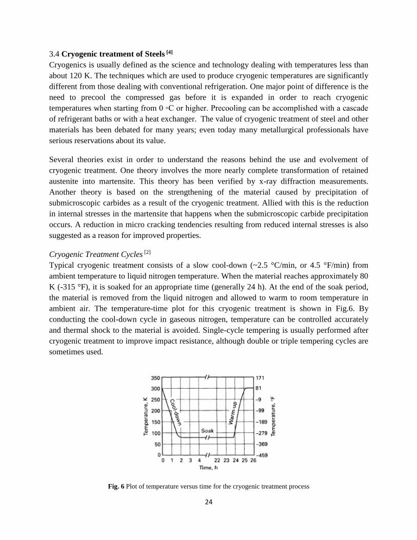
It is relevant to note that martensitic transformation never goes to completion, and the retained
austenite always exists in the structure of high-carbon martensites. Another study [23] suggested
that the reduction of retained austenite, as a transformation into martensite, may improve the
wear resistance of the material. In the particular experiment, samples of HSS tool steel,
especially M2, are subjected to the heat treatment cycles presented in Table 5.
Table 5 Different cycles applied to M2 high speed steel
Different cycles applied to M2 high speed steel
A Quenching from 1250 oC + triple tempering at 560 oC
B Quenching from 1250 oC + 1 cycle 24 h sub-zero at -196 oC+ triple tempering at 560 oC
C Quenching from 1250 oC + 1 cycle 48 h sub-zero at -196 oC+ triple tempering at 560 oC D Quenching from 1250 oC + 3 cycles 48 h sub-zero at -196 oC+ triple tempering at 560 oC E Quenching from 1250 oC + triple tempering at 560 oC+ 1 cycle 48 h sub-zero at -196 oC
Using X-ray difractometer, Seyed Ebrahim Vahdat et a.l. observed that there is a significant
difference in retained austenite between the treated and non-treated samples. The cryogenically
treated material showed nearly 0% of retained austenite into microstructure, in comparison with
the untreated tool steels which retain austenite in a percentage of 25%. However, the
transformation of the retained austenite into martensite did not result in a significant
improvement of wear resistance, at the conditions the sliding abrasion test was carried out.
Literature results showed that, depending on the test parameters such as normal load, average
grain size and type of the abrasive, quantity and shape of the carbides, among others, the
increasing of the amount of retained austenite can lead to an increase or to a decrease in the wear
rate of ferrous alloys. This behavior is regarded with the ability of austenite to harden during
plastic deformation either by workhardening or by martensite transformation.
It is essential to notice that the results depend on the conditions on which the heat treatment has
been carried out. The above statement can be confirmed by the next study. J.y. Huang et a.l
studied the microstructure of cryogenic treated M2 tool steel [20]. The samples were subjected to
austenitization at 1100 oC in a nitrogen atmosphere at 20 Pa, holding for 1 h, followed by
quenching to an ambient temperature in a cool nitrogen gas. Cryogenic treatment was performed
by soaking the samples in liquid nitrogen at -196 oC for 1 week and both treated and non-treated
specimens were tempered at 200 oC in nitrogen atmosphere for 24 h. X-ray diffraction showed no
detection of retained austenite in treated samples, due to small percentage. Although, the volume
fraction of retained austenite was measured to be almost the same in both treated and non-treated
samples, wear resistance was improved in case of cryogenic treatment. Thus, transformation of
retained austenite is not a main factor of influence for wear resistance, for the particular tool
steel.

30
Soaking time can be a significant factor influencing the amount of retained austenite. In a study
of deep cryogenic treatment in tool steel X220CrVMo 13-4 (DIN 1.2380)[19], which is a high-
carbon, high-chromium air-hardening tool steel, A.I. Tyshchenkoa et a.l subjected the samples to
different cycles of heat treatment, including cryogenic treatment. These specimens were held for
austenitization at 1080 oC for 20 min under protective pure argon atmosphere and cooled using
the flow of the cold argon. After quenching, some of the specimens were cooled to -196 or -150
◦C with holding at these temperatures for 24, 36 or 48 h.
Table 6 Retained austenite after different treatment cycles
Cooling after solution treatment Martensite RA Carbide Fe0 Fe1
Quenching at RT 81.7 7.7 10.6 27.2 34.0
RT -196 oC (24h) 86.6 4.1 9.3 24.3 37.3
RT -196 oC (36h) 87.0 3.9 9.1 22.8 38.8
RT -196 oC (48h) 87.3 3.7 9.0 19.9 43.3
RT -196 oC (24h) 89.1 3.5 7.4 15.2 46.3
RT (1 week) -196 oC (24h) 85.6 5.8 8.6 21.2 36.5
From Table 6, it can be observed that the samples which were subjected at -196 ◦C for 48h,
showed the smallest percentage of retained austenite into microstructure, among the other groups
subjected at the same temperature. However, it is essential to notice that the cryogenic cycle at -
150 ◦C was more effective that the one in liquid nitrogen. Moreover, in case of the preliminary
ageing at RT before cryogenic treatment, A.I. Tyshchenkoa et a.l observed that, in comparison
with cryogenic treatment at -196 ◦C for 24h, the stabilization of the retained austenite decreased
the amount of the low-temperature martensite. This behavior is justified by the fact that after
quenching, the austenite-to-martensite transformation does not stop sharply and the
transformation rate decreases for a number of months.
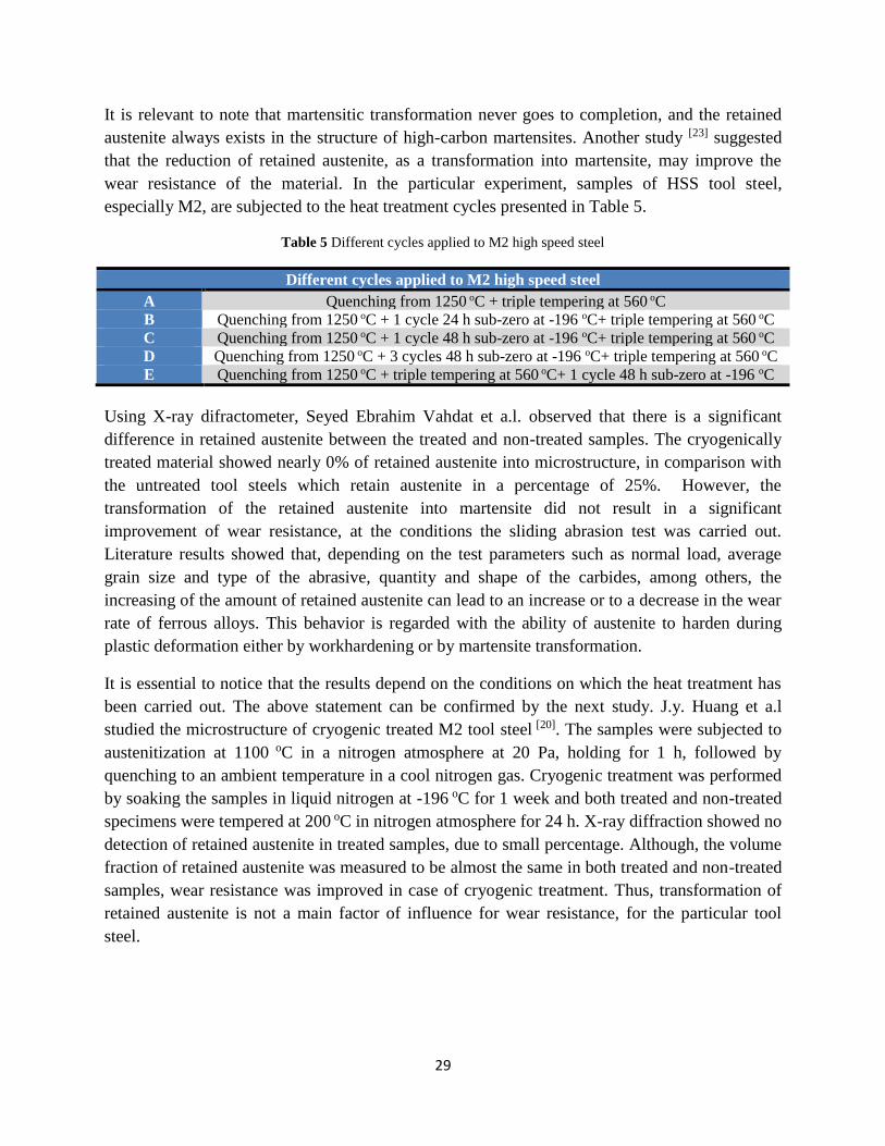
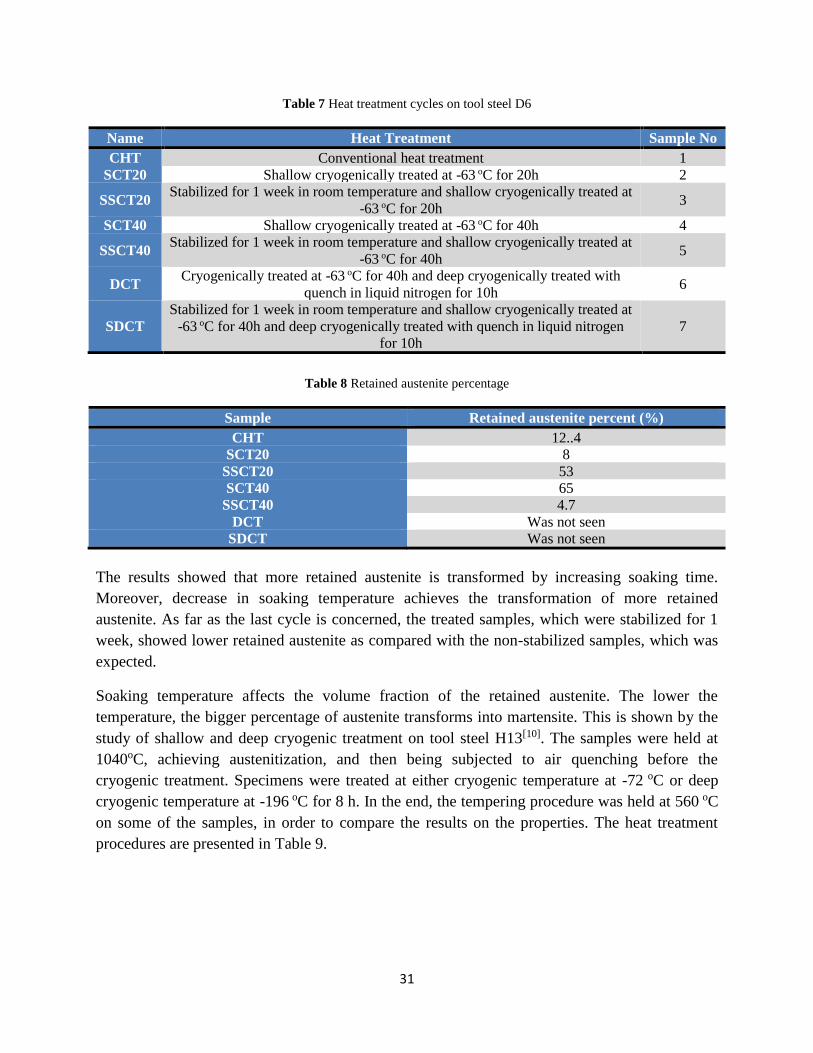
A. Akhbarizadeh et a.l [11] confirmed the above results, after studying the effect of cryogenic
treatment on D6 tool steel. The samples were subjected to different cycles of cryogenic treatment
and were examined for comparison with the conventional heat treatment (Table 7). As far as
deep cryogenic treatment is concerned, retained austenite could not be detected due to its very
small percentage. For the other types of treatment, retained austenite was observed in small
amount (Table 8).
31
Table 7 Heat treatment cycles on tool steel D6
Name Heat Treatment Sample No
CHT Conventional heat treatment 1
SCT20 Shallow cryogenically treated at -63 oC for 20h 2
SSCT20 Stabilized for 1 week in room temperature and shallow cryogenically treated at
-63 oC for 20h 3
SCT40 Shallow cryogenically treated at -63 oC for 40h 4
SSCT40 Stabilized for 1 week in room temperature and shallow cryogenically treated at
-63 oC for 40h 5
DCT Cryogenically treated at -63 oC for 40h and deep cryogenically treated with
quench in liquid nitrogen for 10h 6
SDCT
Stabilized for 1 week in room temperature and shallow cryogenically treated at
-63 oC for 40h and deep cryogenically treated with quench in liquid nitrogen
for 10h
7
Table 8 Retained austenite percentage
Sample Retained austenite percent (%)
CHT 12..4
SCT20 8
SSCT20 53
SCT40 65
SSCT40 4.7
DCT Was not seen
SDCT Was not seen
The results showed that more retained austenite is transformed by increasing soaking time.
Moreover, decrease in soaking temperature achieves the transformation of more retained
austenite. As far as the last cycle is concerned, the treated samples, which were stabilized for 1
week, showed lower retained austenite as compared with the non-stabilized samples, which was
expected.
Soaking temperature affects the volume fraction of the retained austenite. The lower the
temperature, the bigger percentage of austenite transforms into martensite. This is shown by the
study of shallow and deep cryogenic treatment on tool steel H13[10]. The samples were held at
1040oC, achieving austenitization, and then being subjected to air quenching before the
cryogenic treatment. Specimens were treated at either cryogenic temperature at -72 oC or deep
cryogenic temperature at -196 oC for 8 h. In the end, the tempering procedure was held at 560 oC
on some of the samples, in order to compare the results on the properties. The heat treatment
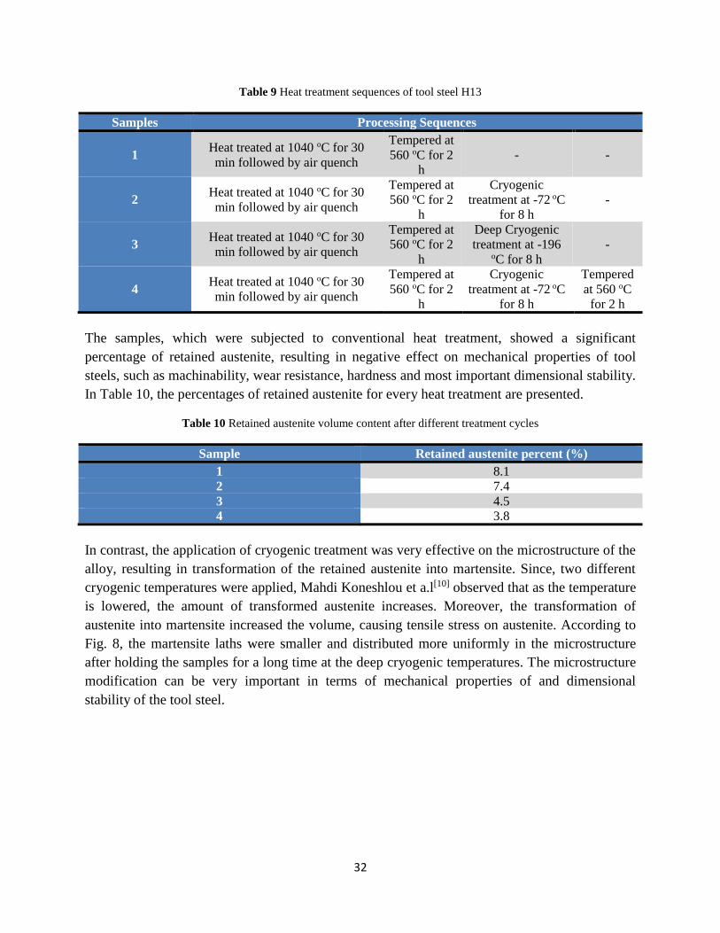
procedures are presented in Table 9.
32
Table 9 Heat treatment sequences of tool steel H13
Samples Processing Sequences
1 Heat treated at 1040 oC for 30
min followed by air quench
Tempered at
560 oC for 2
h
- -
2 Heat treated at 1040 oC for 30
min followed by air quench
Tempered at
560 oC for 2
h
Cryogenic
treatment at -72 oC
for 8 h
-
3 Heat treated at 1040 oC for 30
min followed by air quench
Tempered at
560 oC for 2
h
Deep Cryogenic
treatment at -196
oC for 8 h -
4 Heat treated at 1040 oC for 30
min followed by air quench
Tempered at
560 oC for 2
h
Cryogenic
treatment at -72 oC
for 8 h
Tempered
at 560 oC
for 2 h
The samples, which were subjected to conventional heat treatment, showed a significant
percentage of retained austenite, resulting in negative effect on mechanical properties of tool
steels, such as machinability, wear resistance, hardness and most important dimensional stability.
In Table 10, the percentages of retained austenite for every heat treatment are presented.
Table 10 Retained austenite volume content after different treatment cycles
Sample Retained austenite percent (%)
1 8.1
2 7.4
3 4.5
4 3.8
In contrast, the application of cryogenic treatment was very effective on the microstructure of the
alloy, resulting in transformation of the retained austenite into martensite. Since, two different
cryogenic temperatures were applied, Mahdi Koneshlou et a.l[10] observed that as the temperature
is lowered, the amount of transformed austenite increases. Moreover, the transformation of
austenite into martensite increased the volume, causing tensile stress on austenite. According to
Fig. 8, the martensite laths were smaller and distributed more uniformly in the microstructure
after holding the samples for a long time at the deep cryogenic temperatures. The microstructure
modification can be very important in terms of mechanical properties of and dimensional
stability of the tool steel.

33
Fig. 8 Scanning electron microscopy images of the samples 1–4 after different heat treatment cycle
After the hardening process by cryogenic treatment, material expansion is observed. This
expansion is caused by the phenomenon of transformation of the retained austenite. The
tempering procedure is carried out in order to achieve stabilization and releasing the stress of the
martensitic structure. Thus, most studies carry out mostly three tempering procedures.
Fig. 9 The effect of deep cold treatment on retained austenite for an austenitising temperature of 1070 oC for tool
steel D2.

34
The first tempering manages to release the stress of the martensite and as a result the material
shrinks. During the second tempering, the carbides begin to grow and stabilization is achieved.
Finally, the third tempering has usually no noticeable effect. Such procedure is carried out on the
study of cryogenic treatment on AISI D2 tool steel [30]. According to Cord Henrik Surberg et a.l,
after third tempering, dimensions do not face significant changes (Fig. 10). Moreover, it can be
seen that after the first tempering, the retained austenite remains below 2% with no further
change after the second and third tempering procedure (Fig. 9).
Fig. 10 The effect of a deep cold treatment on dimensional stability
According to the experiment, the samples were subjected to different soaking temperatures and
time. Thus, in regard with the previous studies, it is confirmed that the lower the temperature, the
greater the expansion during deep cryogenic treatment because more retained austenite is
transformed. Dimensional stability is independent of the soaking time during deep cryogenic
treatment (Fig. 11).
Fig. 11 Comparison of dimensional stability after treatment at various deep cold temperatures for 25 min

35
This retained austenite is soft and unstable at lower temperatures that it is likely to transform into
martensite under certain conducive conditions. Thus retained austenite should be alleviated to the
maximum possible before any component or tool is put into service. The degree of undercooling
decides the potential to transform retained austenite to martensite completely.
The transformation of the austenite to martensite in combination with thermal contraction caused
surface tensile residual stress to all the specimens. According to Marcos Pérez and Francisco
Javier Belzunce [28], a slight relaxation in stress was observed, during cryogenic procedure, due
to fine carbides precipitation (Fig. 12). Specifically, during heating up to room temperature after
cryogenic stage, small carbides are formed by clusters. These clusters were made when the
carbon atoms inside the martensitic matrix, segregated to nearby structural defects, during
cryogenic process. Significant improvement on relaxation of stress is observed during first
tempering procedure, as a result of carbide precipitation and decrease in carbon content of
martensite. However, the second and third tempering had no effect on the stress state. The
second tempering is used as a procedure to transform the martensite, which is formed during
cooling of the first tempering. Although, the samples are subjected to third tempering, the new
fresh martensite form cooling of the second tempering can be detected.
Fig. 12 Evolution of the surface stress versus the quenching medium for each stage of the overall heat treatment (Q-
Quenching, C-Cryogenic, T-Tempering

36
2.2 Carbide precipitation
Apart from the transformation of the retained austenite into martensite, deep cryogenic treatment
contributes to the formation of finer martensite laths in the microstructure and initiates
nucleation sites for precipitation of fine carbide particles. The precipitation of finer carbides
results in the enhancement of mechanical properties of the alloy. The subzero procedure results
in facilitating the formation of carbon clustering and increases the carbide density in the
microstructure.
Inside the matrix of tool steel subjected to heat treatment, two types of carbides are observed:
• Primary Carbides (PCs), which form on the grain boundaries during quenching. Although the
formation of the primary carbides has no significant impact on hardness, may lower tool steel
fracture resistance. This leads to quench cracking intergranular fracture of overheated tool
steels, or reduced performance of hot work die steels such as H13.[24]
• Secondary Carbides (SCs), known as transition carbides. These carbides are formed during
the first stage of tempering and are identified as ε-carbides (epsilon-carbides) and η-carbides
(eta-carbides). The transition carbide has an orthorhombic structure isomorphous with
transition metal carbides of the M2C type. The transition carbide is characterized by carbon
contents substantially higher than that of the cementite, Fe3C, which forms at higher
temperatures. Throughout the range of η-carbides formation, a percentage of carbon in the
martensite is retained and randomly dissolved in the retained austenite with the martensite,
during tempering.[24]
J.Y. Huang et a.l [20] observed that the carbides, demonstrated in the microstructure, were
uniformly dispersed. They were localized in certain regions, and their size varied from region to
region. As a result of the precipitation of the fine carbides, wear resistance of material increased
and there was reduction in micro cracking tendency from reduced internal stress.
Fig. 13 TEM micrographs of M2 tool steel after cryogenic treatment and tempering.

37
Fig. 14 TEM micrographs of M2 tool steel after non-cryogenic treatment and tempering. Note that the carbides in
(a) are small, while those in (b) are large.
It is essential to mention that the volume fraction of carbides in the cryogenically treated sample
was higher (11%) than that in the non-cryogenically treated ones (5%) (Fig. 13, 14). The
precipitation of more hard carbides in the cryogenically treated samples resulted in reduction of
carbon and alloy contents in the matrix, which improved the toughness of the matrix. J.Y. Huang
et a.l [20] mentions the fact that the combination of higher carbide content and tougher matrix
enhanced the wear resistance.
A study of cryogenic treatment on W9Mo3Cr4V high speed steel [13], showed the different types
of carbides that are precipitated in the microstructure. Fig. 16 exhibits a non-uniform distribution
of primary carbides and a fairly uniform distribution of secondary carbides in the tempered
martensite matrix. Every SEM picture shows the microstructure for samples cryogenically
treated at 193 K (b), 153K (d), 113 K (f), 77 K (h) respectively. The first picture shows the
microstructure of the samples that are subjected to conventional heat treatment (a). In the
microstructure, , X.G. Yan and D.Y.Li observed resolved prior austenite grain boundaries. As it
can be seen, the large, irregular white regions represent the primary carbides (PCs – Primary
Carbides). The amount, size and distribution of them appear identical irrespective of the type of
heat treatment. This behavior is justified because time and temperature of austenitization are
responsible for the characteristics of the primary carbides. Moreover, there are two types of the
secondary carbides. The SEM pictures show some tiny white patches (SSCs – Small Secondary
Carbides) and some small white regions (LSCs – Large Secondary Carbides). The volume
fraction of the secondary carbides, especially the SSCs, is affected by the heat treatment
condition. Apparently, fraction volume of the secondary carbides increases with the decrease of
the cryogenic temperature.

38
Fig. 15 Quantitative information on the volume fractions of carbides in samples experienced different sub-zero
treatments of W9Mo3Cr4V high speed steel. The volume fraction of carbides is represented by the number of
carbides per unit area
Fig. 15presents that the samples, which were subjected to cryogenic treatment, showed increase
for all the types of carbides, in comparison with the conventional heat treatment. The deep
cryogenic treatment provided increase in secondary carbides, in contrast with the shallow
cryogenic treatment.
Fig. 16 SEM micrographs of samples experienced different heat treatment processes. The microstructure of the
W9HSS samples generally consists of a matrix of tempered martensite and carbides, including primary carbides
(PCs: size45 mm) and secondary carbides (SCs: sizer5 mm), which are further sub-classified as large secondary
carbides (LSCs:1 mm osizer5 mm) and small secondary carbides (SSCs: size r1 mm): (a)SEM micrograph of CONT
(b)SEM micrograph of CT; (c) SEM micrograph of SCT; (d)SEM micrograph of DCT1; (e)SEM micrograph of
DCT2;

39
Seyed Ebrahim Vahdat et a.l examined microstructure of 45WCrV7 tool steel after deep
cryogenic treatment [22]. The specimens were subjected to austenitization at 900 oC for 1h, then
deep cryogenic treatment at -195 oC for 24h, 36h, 48h and finally they are tempered at 200 oC for
1h, 2h, 3h. (Fig. 17).
Fig. 17 DCT cycle
According to researchers, the first mechanism of precipitation of secondary carbide (SCs) is the
result by the expansion from the transformation of retained austenite into martensite. The second
mechanism is caused by the difference in thermal contraction of the phases. The below SEM
picture (Fig. 18) shows the different types of carbides inside the matrix of the samples.
Fig. 18 SEM image, 20 kV, in which letters A, B and C show different carbides and D is the matrix of 45WCrV7

40
Letters A and C represent the primary carbides (M7C3) and letter B represent the secondary
carbides (M23C6). Letter D is the matrix of the material. The primary carbides are characterized
by grey color, since they have higher carbon content that the secondary carbides. Thus, region B
is presented by a white spherical phase. Letter M represents either W, or Cr, Si, Fe.
Fig. 19 PC, SC and tertiary carbide volume fraction (a) tempering time trend and (b) soaking time trend
Seyed Ebrahim Vahdat et a.l [22] mentions that, according to Fig. 19, volume fraction of the
secondary carbides increases with the tempering time. Greater effect on the increase of the
secondary carbides is given by soaking time, due to defect density around the PCs in the phase
matric. However, volume fraction of the primary carbides remains constant irrespective of
tempering and soaking time. Another point worth mentioned is that specimens 002, 003 have the
volume fraction of SCs almost constant, since the conditions of formation of SC were not
facilitated. In conclusion, cryogenically treated samples showed precipitation of fine secondary
carbides. This subzero procedure increased their volume fraction and their population density,
causing the formation of more homogenous and refined microstructure.
B. Podgornik et a.l [9] used high C and V content cold-work steel A2, cold work tool steel A1
lower C and high W and Co content and high speed tool steel B1 and examined the
microstructure after conventional heat treatment (Fig. 20) and deep cryogenic treatment at -196
oC for 25 h. Three groups of the materials were formed (Table 11).

41
Table 11 Different treatment cycles for tool steels A1, A2, B1
Group Austenitizing DC Treatment Tempering
Temp [oC] Soaking
time [min] Temp [oC]
Immersion
time [h] Temp [oC] Time [h]
A1
1 1130 6 - - 520/520/500 2/2/2
2 1100 20 - - 500/500/480 2/2/2
3 1070 20 - - 585/585/565 2/2/2
1P 1130 6 -196 25 520 2
2P 1100 20 -196 25 500 2
3P 1070 20 -196 25 585 2
A2
1 1180 6 - - 540/540/510 2/2/2
2 1180 6 - - 560/560/530 2/2/2
3 1180 6 - - 500/500/480 2/2/2
1P 1180 6 -196 25 540 2
2P 1180 6 -196 25 560 2
3P 1180 6 -196 25 500 2
B1
1 1180 2 - - 530/530/500 2/2/2
2 1100 20 - - 560/560/530 2/2/2
3 1030 20 - - 570/570/540 2/2/2
1P 1180 2 -196 25 530 2
2P 1100 20 -196 25 560 2
3P 1030 20 -196 25 570 2
Fig. 20 Typical SEM images for analysis of undissolved eutectic carbides (MC—grey/black and M6C—white) after
conventional heat treatment from the highest austenitizing temperature (1180 OC) for (a) tool steel A1, (b) tool steel
A2 and (c) tool steel B1 tool steel A2

42
Fig. 21 Microstructure of A1 cold work tool steel after (a) quenching, (b) conventional triple tempering (group 1)
and (c) DCT and single tempering (group 1P)
Table 12 Quantitative metallographic analysis (a below the detection limit)
Group
Conventional heat treatment Deep Cryogenic treatment (P)
Grain size
Volume
Fraction
[%]
Grain size
Volume
Fraction
[%]
[μm] ISO
643 Carbides RA [μm]
ISO
643 Carbides RA
A1
1 3.7 G13 4.43±0.37 <1.0a 3.8 G13 4.38±0.27 <1.0a
2 2.9 G14 4.85±0.43 <1.0a 2.9 G14 4.98±0.38 <1.0a
3 2.6 G14 5.05±0.36 <1.0a 2.8 G14 5.50±0.27 <1.0a
A2
1 2.1 G15 19.40±1.33 <1.0a 2.0 G15 19.25±0.53 <1.0a
2 1.8 G15 19.25±0.65 <1.0a 1.8 G15 18.20±1.43 <1.0a
3 2.2 G15 19.30±0.63 <1.0a 1.5 G15 18.76±0.99 <1.0a
B1
1 2.3 G15 16.82±1.21 <1.0a 2.1 G15 16.20±1.41 <1.0a
2 2.1 G15 18.17±2.06 <1.0a 1.8 G15 17.84±1.59 <1.0a
3 1.9 G15 20.49±1.70 <1.0a 2.0 G15 20.72±1.70 <1.0a
As it can be seen from Table 12, for tool steel A1, the grain size of the prior-austenite stayed
between 2.6 and 3.8 μm in the microstructure. Moreover, volume fraction of the fine uniformly
distributed carbides (eutectic carbides of MC – grey/black, M6C – white) reached the value of
5%. As far as the retained austenite is concerned, the volume fraction after cryogenic treatment
and tempering was below the detection limit (1%) (Fig. 21). It is essential to notice that decrease
in tempering temperature caused increase in the volume fraction of the carbides. However, deep
cryogenic treatment had no significant effect on both retained austenite and volume of carbides.
In the case of tool steel A2, the increased content of C and V caused reduction to prior-austenite
grain size, in contrast with A1. Moreover, the grain size of the undissolved eutectic carbides
showed great increase, being mainly of MC type. Similar results were observed for the high
speed steel B2, although the carbides are both MC and M6C. However, none of the three types of

43
tool steels showed significant effect in grain size and carbide volume fraction after deep
cryogenic treatment.
The advantage of cryogenic treatment is the formation of fine uniformly distributed carbides,
which have significant positive effects in strength, fracture toughness and structure homogeneity.
Strength and fracture toughness are described in the next paragraph.
As discussed above, in tool steels there are three types of carbides morphologies: large carbides,
which do not dissolve during austenitization, secondary microcarbides, distributed during
quenching, and secondary nanocarbides, formed during tempering. Thus, cryogenic treatment
affects only the nanocarbides during tempering, and let primary and secondary carbides keep
their characteristics.
For cryogenically treated tool steel H13 samples, microstructural analysis exhibited expected
tempered martensite, involving fine spherical homogeneously dispersed carbides [28]. Marcos
Pérez and Francisco Javier Belzunce presented that there is a significant difference in the
carbides precipitation between the treated and non-treated samples (Fig. 22). HT1 treatment
cycle exhibited a relatively coarse and sometimes elongated appearance. However, samples
subjected to cryogenic treatment in cycle HT4 showed a more uniform distribution of finer
carbides. Thus, cryogenic treatment provided a homogeneous distribution of finer carbides and
increases their volume fraction. It is important to mention that the characteristics of the carbide
network have a positive effect in toughness of H13.
According to the study, the precipitation of fine η-carbides (transition carbides) was observed in
the structural defects created during the quenching and cryogenic stages. Moreover,, there was an
in-situ nucleation of M3C carbides (cementite) on η-carbides. The final formation of alloy
carbides was responsible for secondary hardening. In the case of chromium containing tool
steels, M3C carbides transform to M7C3, whereas in tool steels containing molybdenum, M3C
carbides transform to M2C. As H13 steel has both chromium and molybdenum, M3C carbides are
supposed to transform into M7C3 and M2C.
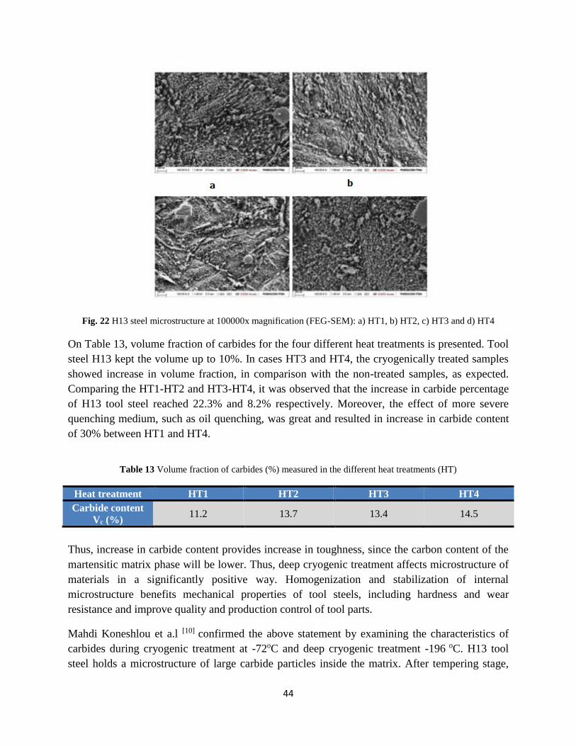
44
Fig. 22 H13 steel microstructure at 100000x magnification (FEG-SEM): a) HT1, b) HT2, c) HT3 and d) HT4
On Table 13, volume fraction of carbides for the four different heat treatments is presented. Tool
steel H13 kept the volume up to 10%. In cases HT3 and HT4, the cryogenically treated samples
showed increase in volume fraction, in comparison with the non-treated samples, as expected.
Comparing the HT1-HT2 and HT3-HT4, it was observed that the increase in carbide percentage
of H13 tool steel reached 22.3% and 8.2% respectively. Moreover, the effect of more severe
quenching medium, such as oil quenching, was great and resulted in increase in carbide content
of 30% between HT1 and HT4.
Table 13 Volume fraction of carbides (%) measured in the different heat treatments (HT)
Heat treatment HT1 HT2 HT3 HT4
Carbide content
Vc (%) 11.2 13.7 13.4 14.5
Thus, increase in carbide content provides increase in toughness, since the carbon content of the
martensitic matrix phase will be lower. Thus, deep cryogenic treatment affects microstructure of
materials in a significantly positive way. Homogenization and stabilization of internal
microstructure benefits mechanical properties of tool steels, including hardness and wear
resistance and improve quality and production control of tool parts.
Mahdi Koneshlou et a.l [10] confirmed the above statement by examining the characteristics of
carbides during cryogenic treatment at -72oC and deep cryogenic treatment -196 oC. H13 tool
steel holds a microstructure of large carbide particles inside the matrix. After tempering stage,

45
precipitation of finer carbides was observed, in case of deep cryogenic treatment. Moreover,
through the scanning electron microscope picture (Fig. 23), there were two different types of
carbides: (a) chromium (black), (b) and molybdenum (white) carbides. The chromium carbides
were the dominant carbides in the microstructure.
Figure 23 Scanning electron microscopy images showing the effect of deep cryogenic treatment on th chromium
(black) and molybdenum (white) carbides distribution of sample 1 (a) and sample 4 (b)
The sample, which was subjected in deep cryogenic treatment, showed a fine and more uniform
distribution of spherical carbides in microstructure after tempering. The percentage of carbides
was measured to be 5.8% for non-treated sample. For shallow cryogenic treatment, the
percentage was not affected and remained similar. However, deep cryogenically treated sample
showed increase in value which reached 6.9%. The increase in volume fraction is caused by the
transformation of the retained austenite to martensite and the precipitation of more carbides. The
more spherical and uniform carbides benefit hardness which is an essential factor in tool steel
applications. Furthermore, it is confirmed that deep cryogenic treatment results in formation of
finer martensite laths in the microstructure. This formation is a main factor which initiates
nucleation sites for precipitation of fine carbide particles, resulting in enhancement of
mechanical properties of the H13 tool steel

46
Section 3: Hardness and Fracture Toughness
Cryogenic treatment affects microstructure of tool steel, enhancing mechanical properties,
especially hardness and wear resistance. In general, materials with a face-centered cubic (fcc)
lattice keep their ductility at cryogenic temperatures, whereas body-centered cubic (bcc) and
hexagonal-closed packed (hcp) materials become brittle (jawahir2016). The increase in hardness
is caused by the transformation of austenite to martensite, resulting in great martensite content.
Another factor is the precipitation of finer carbides, uniformly distributed in matrix.
A. Akhbarizadeh et a.l [11] proved the above statement by subjecting D6 tool steel to cryogenic
treatment. According to mechanical properties of D6, hardness without heat treatment reaches
the value of 46 Rockwell C. After carrying out the different types of hardening treatments, it was
observed that deep cryogenic treatment provided greater increase in hardness of material (Table
4). Although, shallow cryogenic treatment showed higher hardness than conventional treatment,
in the case of deep cryogenic process, the combination of transformed retained austenite with
more homogenized chromium carbide distribution and higher chromium carbide percentage
exhibited better results. Compared with the non-stabilized samples, the stabilized ones did not
show significant increase in hardness.
Table 14 The hardness (HRC) of the heat-treated D6 tool steel samples after and before temper
Sample After tempering Before tempering
SHT 62±0.5 64±0.7
SCT20 62.5±0.6 65±0.5
SSCT20 63.3±0.4 65.5±0.4
SCT40 63±0.5 65.5±0.3
SSCT40 63.5±0.6 66±0.5
DCT 64±0.4 66.7±0.4
SDCT 64.2±0.3 67±0.5
Hardness and fracture toughness have an inversely proportional relationship. In fact, deep
cryogenic treatment causes increase in hardness but decrease in toughness. Debdulal Das et a.l [18] came to the conclusion that fracture toughness decreases almost linearly with increase in both
macrohardness and microhardness (Fig. 24). The specimens were subjected to the below heat
treatments:
• CHT – Conventional HT
• CT – Cold Treatment at -75oC for 5 min
• SCT – Shallow Cryogenic Treatment at -125oC for 5 min
• DCT – Deep Cryogenic Treatment at -196oC for 36 hrs

47
The deep cryogenically treated samples of D2 tool steel showed moderate fracture toughness, in
contrast with higher value of hardness. The variations of the fracture toughness between the
different heat treatments were due to alterations of the matric microstructure. The matrix of all of
the studied specimens consisted of secondary carbide particles in the tempered martensite, while
the presence of retained austenite had been identified only for the conventionally treated and cold
treated specimens. Since the characteristics of the secondary carbides were modified by the
conditions of the heat treatments, the variations were related to these microstructure alterations.
Fig. 24 Variations of fracture toughness with Vickers (a) macrohardness and (b) microhardness of the investigated
specimens. CHT: conventionally heat treated, CT: cold treated, SCT: shallow cryogenically treated, DCT: deep
cryogenically treated.
It can be seen that the degree of improvement in hardness varies with the type of cryogenic
treatment (Fig. 25). Deep cryogenic treatment shows higher value of hardness than shallow type.
Moreover, it can be seen that the subzero treatment has a more significant effect in case of
microhardness, compare to macrohardness. In fact, study [27] shows that the improvement in
microhardness over conventional treatment reaches 8.1%, in contrast with 11.4% for bulk
hardness. The increase in bulk hardness can be related to reduction of austenite, improvement of
amount of secondary carbides and tough tempered martensite.
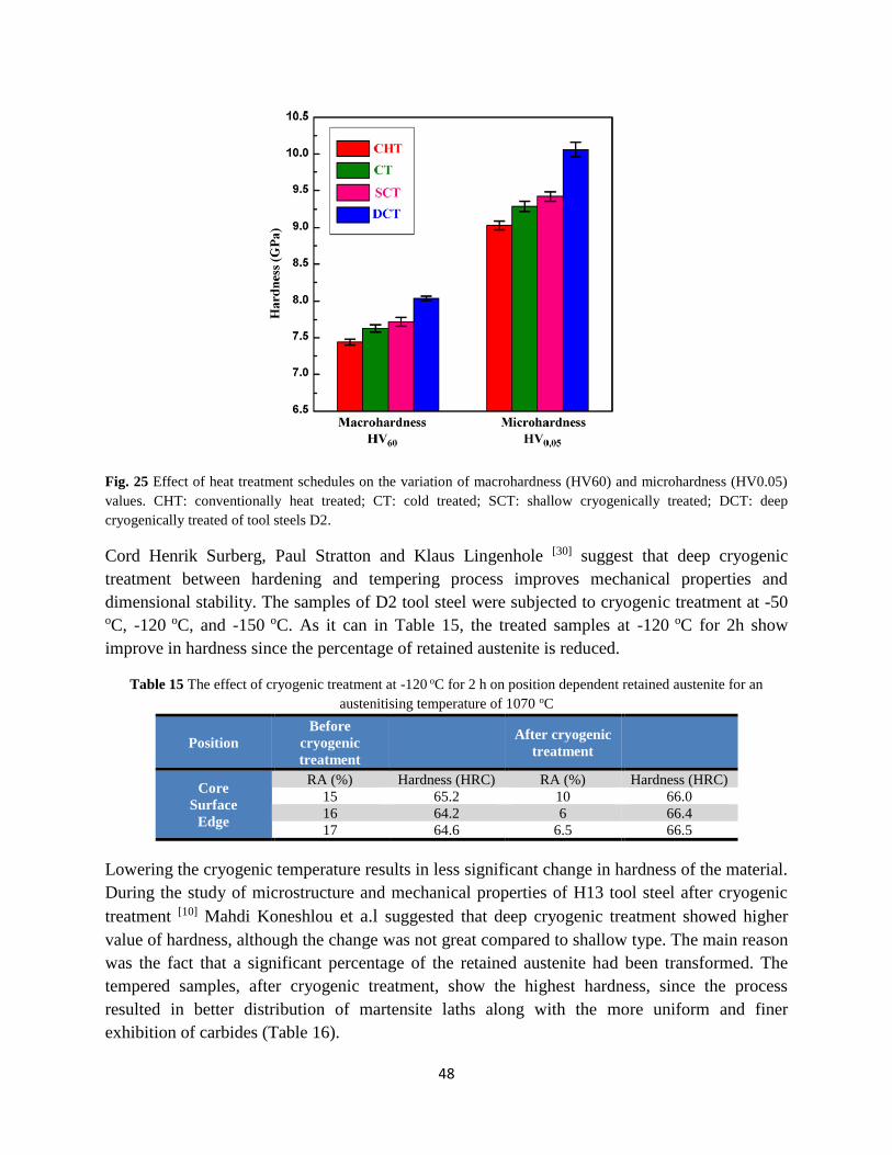
48
Fig. 25 Effect of heat treatment schedules on the variation of macrohardness (HV60) and microhardness (HV0.05)
values. CHT: conventionally heat treated; CT: cold treated; SCT: shallow cryogenically treated; DCT: deep
cryogenically treated of tool steels D2.
Cord Henrik Surberg, Paul Stratton and Klaus Lingenhole [30] suggest that deep cryogenic
treatment between hardening and tempering process improves mechanical properties and
dimensional stability. The samples of D2 tool steel were subjected to cryogenic treatment at -50 oC, -120 oC, and -150 oC. As it can in Table 15, the treated samples at -120 oC for 2h show
improve in hardness since the percentage of retained austenite is reduced.
Table 15 The effect of cryogenic treatment at -120 oC for 2 h on position dependent retained austenite for an
austenitising temperature of 1070 oC
Position
Before
cryogenic
treatment
After cryogenic
treatment
Core
Surface
Edge
RA (%) Hardness (HRC) RA (%) Hardness (HRC)
15 65.2 10 66.0
16 64.2 6 66.4
17 64.6 6.5 66.5
Lowering the cryogenic temperature results in less significant change in hardness of the material.
During the study of microstructure and mechanical properties of H13 tool steel after cryogenic
treatment [10] Mahdi Koneshlou et a.l suggested that deep cryogenic treatment showed higher
value of hardness, although the change was not great compared to shallow type. The main reason
was the fact that a significant percentage of the retained austenite had been transformed. The
tempered samples, after cryogenic treatment, show the highest hardness, since the process
resulted in better distribution of martensite laths along with the more uniform and finer
exhibition of carbides (Table 16).

49
Table 16 Ultimate tensile strength and hardness of samples H13 tool steel
Samples Ultimate tensile
strength (MPa) Hardness (HRC) Impact energy (J)
1 1580 49 15.4
2 1640 51 16.1
3 1695 55 17.3
4 1720 59 18.2
Although, it seems that cryogenic treatment affects in a positive way the hardness of the
material, the degree of improvement is related to austenitization temperature. B. Podgornik et a.l [9] suggested that the higher austenitization temperature provides the highest value of hardness
(Fig. 26). A1 tool steel reached the highest hardness, but the lowest fracture toughness at the
highest austenitizing temperature of 1130 oC. On the other hand, A1 tool steel has the highest
toughness and lowest hardness value at the lowest austenitizing temperature of 1070 o C and high
tempering temperature of 500 oC. As far as B1 high speed steel is concerned, similar result are
observed, reaching the highest value of hardness at the highest austenitizing temperature of 1180
oC and the highest value of fracture toughness at the lowest austenitizing temperature of 1030 o C
and high tempering temperature of 530 oC . In the case of A2, austenitizing temperature remains
constant for all three groups at 1180 oC. Maximum hardness and maximum toughness is reached
at tempering temperature of 540 oC.
In conclusion, it can be seen that deep cryogenic treatment at -196 oC has no significant effect in
hardness of A1 tool steel, although there is improvement in fracture toughness. In Group 1,
fracture toughness increased at almost 70%, for an extremely small drop of hardness. For Group
2, hardness is maintained at the same level and the increase in fracture is lower than Group 1.
The lower degree of change is observed in Group 3, in which toughness increases only about
10%, whereas hardness remains constant. According to the study, this behavior can be related to
plastic deformation of primary martensite accompanying martensitic transformation, partial dis-
solution of carbide particles and formation of carbon clusters. This plastic deformation, in
combination with educed amount of dissolved carbon in the martensite and finer and more
homogeneous carbides precipitation improved fracture toughness. In the case of B1,
improvement of toughness reaches 10% in Group 1 at the highest value of hardness, whereas in
two other groups increase reaches 5%. Thus, deep cryogenic treatment had no effect on B1 high
speed steel hardness and fracture toughness. The small effect can be attributed to very small
volume fraction of retained austenite in B1 steel after quenching, but mainly to high volume
fraction of undissolved eutectic carbides. Finally, for A2 tool steel, deep cryogenic treatment had
negative effect, since in all three groups, it led to reduction in fracture toughness. In fact, in two
of the three groups, reduction in hardness is observed. This behavior is justified by the presence
of undissolved eutectic carbides, as for B1.

50
Fig. 26 Effect of deep cryogenic treatment on (a) hardness, (b) fracture toughness
Seyed Ebrahim Vahdat et a.l[22] compared the treated specimens with the non-treated ones, for
tool steel 45WCrV7, and discovered that hardness of DCT specimens showed 9-12% increase.
The non-treated material was subjected to oil quenching and tempering at 450 oC, whereas the
deep cryogenically treated samples were quenched in water prior to DCT. Improvement in both
toughness and hardness was observed in specimens, which were subjected to cryogenic treatment
at -196 oC for 36h and tempering at 200 oC for 1h and specimens subjected to cryogenic
treatment at -196 oC for 48h and tempering at 200 oC for 2h.
For the treated 45WCrV7 tool steel, maximum toughness is achieved by simultaneously
increasing soaking and tempering times. However, it is essential to value time and cost of
production. Thus, specimens, subjected to cryogenic treatment at -196 oC for 36h and tempering
at 200 oC for 1h, is a more feasible option. On the other hand, maximum hardness is obtained by
increasing either soaking or tempering times. In this case, a more feasible option would be the
specimens which were subjected to cryogenic treatment at -196 oC for 24h and tempering at 200
oC for 3h.

51
3 Cryogenic treatment in different stages and in combination with surface treatments
Microstructure and mechanical properties can be affected by the conditions on which cryogenic
treatment is carried out. In many cases, cryogenic treatment is held after tempering procedure. In
other cases, surface treatment, especially TiN coating is used before or after cryogenic treatment.
The effect of these combinations is examined in multiple studies, which are presented below.
The process of nitriding is a ferritic thermochemical treatment and usually involves the
introduction of atomic nitrogen into the ferrite phase in the temperature range 500-590 °C and
consequently no phase transformation occurs on cooling to room temperature. The method was
first used at the end of the 1920s and since then its application has continuously spread, due
among other things to the fact that the process has been further developed and can now be
applied to a much larger number of steels than was originally thought possible
D. Mohan Lal et a.l [7] used samples of M2, T1, D3 tool steels and subjected them to cryogenic
treatment before and after tempering, as well as coating with titanium before and after the
subzero process (Table 17).The study showed that the samples with prior tempering exhibited
69% and 33.9% improvement on M2 and D3 respectively. However, post tempering procedure
improved the above tool steel samples at a percentage of 86.6% and 48% respectively. Hence,
tempering procedure after cryogenic treatment is a more desirable option. This can be attributed
to stabilization of carbides and microstructural phases during tempering process, which inhibits
further transformation during cryogenic treatment. Moreover, cryogenic treatment is carried out
at a very slow rate for cooling and heating. In that way, the process itself relieves the brittleness
and stress accumulated. As a result, a post tempering procedure relieves any brittleness
remaining.
Table 17 Different hardening treatment cycles
Cases Nomenclature followed
Hardened and tempered SHT
Cryotreated at 93 K for 24 h CT (93/24)
Cryotreated at 133 K for 24 h CT (133/24)
Cryotreated at 163 K for 24 h CT (163/24)
Cryotreated at 93 K for 6 h CT (93/6)
Cryotreated at 93 K for 6 h and
quenched in LN2 for 2 h CT (93/6) + LN2/2
Tempered and cryotreated at 133
K for 24 h TCT (133/24)
Tempered and cryotreated at 93
K for 24 h TCT (93/24)
Titanium nitride coated TiN
Cryotreated (CT 93/24) and then
coated with Titanium CT + TiN
Titanium nitride coated and then
cryotreated (CT 93/24) TiN + CT

52
Fig. 27 Flank wear versus machining time for different cases
From Fig. 27, it can be observed that TiN-coating caused 48.4%, 42%, 41% improvement while
cryogenic treatment showed 110.2%, 86.6% and 48% in T1, M2, D3 steels, respectively. Thus, it
is observed that cryotreated tools outperformed TiN-coated tools, while the cost of TiN coating
and cryogenic treatment were 25% and 10% of the tool cost, respectively. The case of coating
the cryogenically treated samples showed improvement of 205.3%, 153% and 146% for T1, M2,
D3 respectively. On the other hand, a prior coating treatment at the treated samples caused less
improvement, reaching the percentage of only 104% and 109% in M2, D3 respectively. Hence,
cryogenic treatment on TiN coated samples is not favorable, since it results in shorter tool life.
This may be attributed to the uneven contraction during cryotreatment of the coating material
and the substrate leading to incipient cracks at the interface. Hence cryotreatment should not be
done after TiN coating.

53
The process of Nitriding was, also, carried out for four tool steel grades: X38CrMoV5-1,
55NiCrMoV6 and Swedish steel grades Uddeholm HOTVAR and Uddeholm QRO 90 Supreme.
[Error! Reference source not found.] The samples were nitrited both before and after cryogenic treatment.
The impact in hardness of X38CrMoV5-1tool steel is distributed on Fig. 28.
Fig. 28 Averages and 95% confidence intervals of surface hardness HV5 of X38CrMoV5-1 tool steel specimens
after hardening and tempering and after various types of additional treatment
It can be observed that, in comparison with the prior nitriding hardening process, post nitriding
treatment exhibits greater value of hardness for the particular tool steel sample. Moreover, in the
case of conventional heat treatment and then nitriding, the samples show higher value of
hardness than the process of hardening + nitriding + cryogenic treatment. However, according to
researchers the drop in hardness for the second case mentioned was insignificant and fell within
statistical error. Similar relations between the different hardening processes are shown on the
below distribution (Fig. 29). In the case of the combination of cryogenic treatment followed by
nitriding, extremely high value of hardness was achieved at great depth from surface. Similar
changes in microhardness were seen for the HOTVAR and QRO 90 Supreme steel as well. The
process of cryogenic treatment carried out prior to nitriding and structural transformations
associated with this process seem to facilitate diffusion nitriding, thus affecting both the depth
and the hardness of the internal nitrogen hardening zone.

54
Fig. 29 Microhardness profiles of X38CrMoV5-1 tool steel specimens after hardening and tempering and after
various types of additional treatment
The volume fraction of retained austenite in samples treated by DCT is related to the sequence
between cryogenic treating and tempering. The above statement is justified by the study of
microstructure and hardness of tool steel Cr8Mo2SiV, during different heating treatments and
cycles. [17] The cryogenically treated samples were austenitized at 1040 oC, quenched in oil and
then DCT treated in different cycles at -196 oC in liquid nitrogen, whereas the non-treated ones
were subjected to conventional hardening and tempered at 210 oC in a vacuum furnace under
flowing argon atmosphere (Table 18).
Table 18 Different cycles of heat treatment for tool steel Cr8Mo2SiV
Groups Details of treatment Nomenclature
No.1 Hardening & tempering (2 times) HT
No.2 Hardening & DCT (2h) & tempering (2 times) HCT2
No.3 Hardening & DCT (24h) & tempering (2 times) HCT24
No.4 Hardening & tempering (2 times) & DCT (24h) HTC
No.5 Hardening & DCT (3 times, 1h) & tempering (2
times) HC3T
No.6 Hardening & tempering (1 time) & DCT (24h) &
tempering (1 time) HTCT
As it was discussed in previous paragraphs, the higher hardness of the cryogenic treated samples
is due to the decrease of the retained austenite. Fig. 30 shows the XRD profiles associated with
the martensite reflections and the carbon content of martensite for all DCT treating cycles. The
results show the carbon content in the martensite decreased when prolonger the soaking time in
the liquid nitrogen for the quenched samples. Executing the deep cryogenic treatment after
tempering, increases the volume fraction of retained austenite in a higher level in contrast with

55
the case of subzero treatment prior to tempering (Table 19). The possible reason is the retained
austenite stabilized after tempering and the stabilized retained austenite is beneficial to
toughness.
Table 19 Retained austenite percentage according to every cycle
Nomenclature Retained austenite percent (%)
HT 23.25
HCT2 2.87
HCT24 2.79
HTC 4.65
HC3T 3.05
HTCT 5.72
Fig. 30 The carbon content in martensite for all heat treatment cycles
Shaohong Li, et a.l observed that deep cryogenic treatment after tempering achieves increase in
toughness, whereas hardness is not affected. The reason can be found in the precipitation of
carbides during tempering. Moreover, the samples, which were subjected to deep cryogenic
treatment before tempering, show higher value of hardness [HCT2 (+2.5HRC) and HCT24
(+3.5HRC)] than the ones in the case of prior tempering. When the samples repeated several
times in the liquid nitrogen, the hardness increased as high as carrying out the deep cryogenic
treatment between quenching and tempering for 2 h, and the lower toughness was obtained. The
reason is probably the internal stress increased and micro cracks produced when the samples
repeated several times in the liquid nitrogen. It is indicated that the hardness obviously increased
when carried out the deep cryogenic treatment between quenching and tempering.
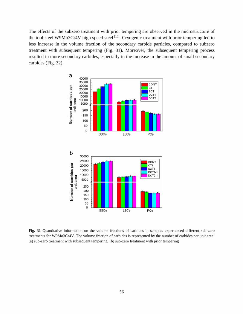
56
The effects of the subzero treatment with prior tempering are observed in the microstructure of
the tool steel W9Mo3Cr4V high speed steel [13]. Cryogenic treatment with prior tempering led to
less increase in the volume fraction of the secondary carbide particles, compared to subzero
treatment with subsequent tempering (Fig. 31). Moreover, the subsequent tempering process
resulted in more secondary carbides, especially in the increase in the amount of small secondary
carbides (Fig. 32).
Fig. 31 Quantitative information on the volume fractions of carbides in samples experienced different sub-zero
treatments for W9Mo3Cr4V. The volume fraction of carbides is represented by the number of carbides per unit area:
(a) sub-zero treatment with subsequent tempering; (b) sub-zero treatment with prior tempering
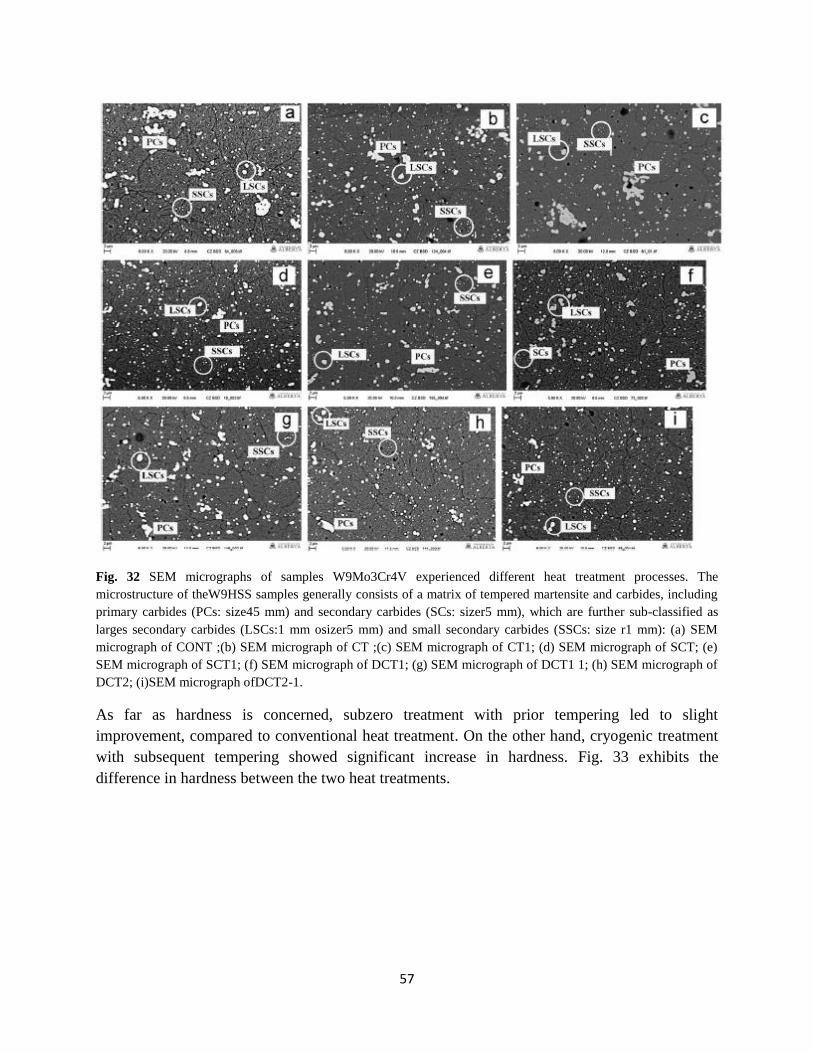
57
Fig. 32 SEM micrographs of samples W9Mo3Cr4V experienced different heat treatment processes. The
microstructure of theW9HSS samples generally consists of a matrix of tempered martensite and carbides, including
primary carbides (PCs: size45 mm) and secondary carbides (SCs: sizer5 mm), which are further sub-classified as
larges secondary carbides (LSCs:1 mm osizer5 mm) and small secondary carbides (SSCs: size r1 mm): (a) SEM
micrograph of CONT ;(b) SEM micrograph of CT ;(c) SEM micrograph of CT1; (d) SEM micrograph of SCT; (e)
SEM micrograph of SCT1; (f) SEM micrograph of DCT1; (g) SEM micrograph of DCT1 1; (h) SEM micrograph of
DCT2; (i)SEM micrograph ofDCT2-1.
As far as hardness is concerned, subzero treatment with prior tempering led to slight
improvement, compared to conventional heat treatment. On the other hand, cryogenic treatment
with subsequent tempering showed significant increase in hardness. Fig. 33 exhibits the
difference in hardness between the two heat treatments.

58
Fig. 33 Hardness values of samples experienced different heat treatment processes in different temperature ranges
(CONT, CT, SCT, and DCT) for W9Mo3Cr4V
As illustrated, the sub-zero treatment with subsequent tempering is more effective in
strengthening the material than in the case with prior tempering. For sub-zero treatments with
subsequent tempering, SCT W9 HSS samples showed significantly higher hardness than CONT
samples. The increase in hardness of DCT1 and DCT2 samples is trivial when compared with the
SCT sample. The shallow cryogenic treatment boosted the sample hardness due to near complete
transition of soft retained austenite to relatively hard martensite. However, when the sample was
subjected to deep cryogenic treatment, no further improvement in hardness was observed as
compared to SCT sample. The reason is that the deep cryogenic temperature produced smaller
secondary spherical carbides, which could be more beneficial to the fracture tough- ness but may
not lead to significant improvement in hardness. For sub-zero treatments with prior tempering,
the improvement in hardness is slight, compared to CONT samples.
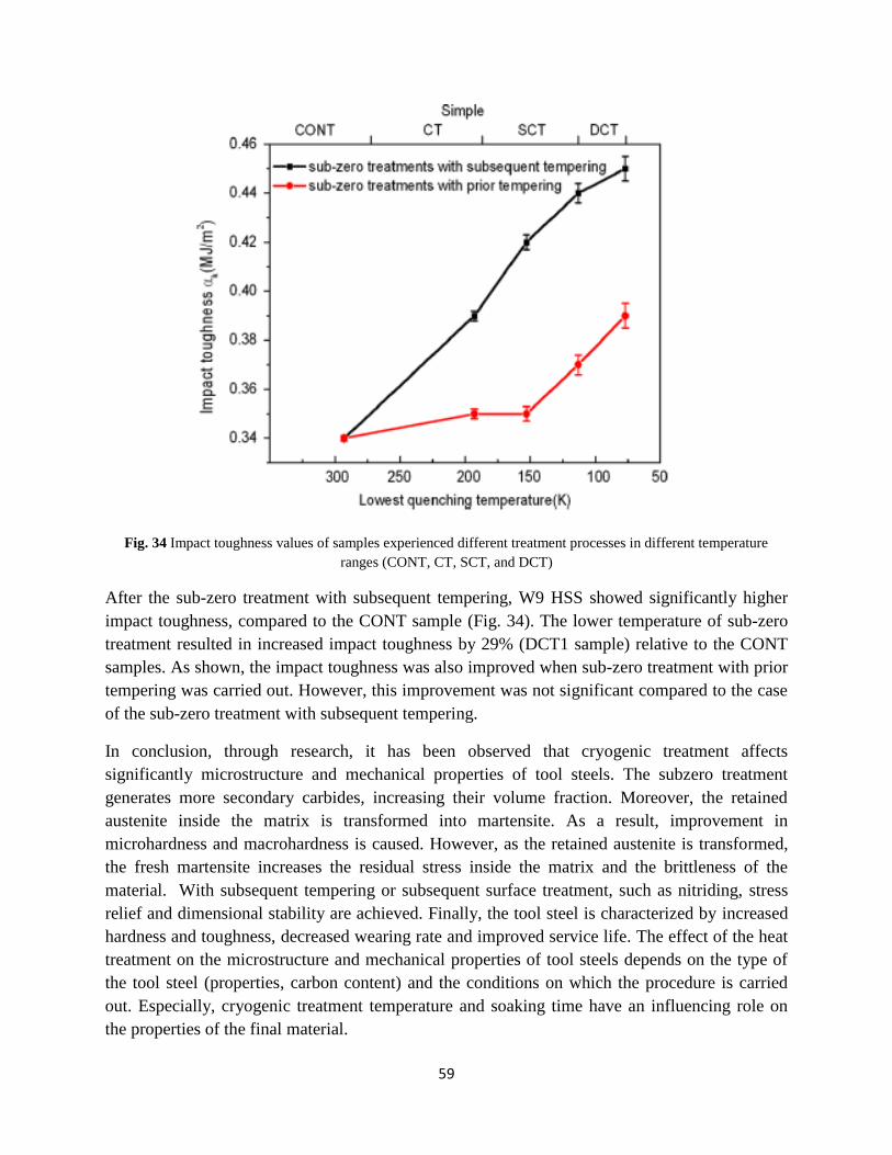
59
Fig. 34 Impact toughness values of samples experienced different treatment processes in different temperature
ranges (CONT, CT, SCT, and DCT)
After the sub-zero treatment with subsequent tempering, W9 HSS showed significantly higher
impact toughness, compared to the CONT sample (Fig. 34). The lower temperature of sub-zero
treatment resulted in increased impact toughness by 29% (DCT1 sample) relative to the CONT
samples. As shown, the impact toughness was also improved when sub-zero treatment with prior
tempering was carried out. However, this improvement was not significant compared to the case
of the sub-zero treatment with subsequent tempering.
In conclusion, through research, it has been observed that cryogenic treatment affects
significantly microstructure and mechanical properties of tool steels. The subzero treatment
generates more secondary carbides, increasing their volume fraction. Moreover, the retained
austenite inside the matrix is transformed into martensite. As a result, improvement in
microhardness and macrohardness is caused. However, as the retained austenite is transformed,
the fresh martensite increases the residual stress inside the matrix and the brittleness of the
material. With subsequent tempering or subsequent surface treatment, such as nitriding, stress
relief and dimensional stability are achieved. Finally, the tool steel is characterized by increased
hardness and toughness, decreased wearing rate and improved service life. The effect of the heat
treatment on the microstructure and mechanical properties of tool steels depends on the type of
the tool steel (properties, carbon content) and the conditions on which the procedure is carried
out. Especially, cryogenic treatment temperature and soaking time have an influencing role on
the properties of the final material.

60
Chapter IV – Experimental Procedure
Section 1: Introduction
In the present thesis, the behavior of hot work tool steel Uddeholm Orvar 2M (AISI H13/W. Nr.
1.2344, 0.39%C, 1%Si, 0.4%Mn, 5.3%Cr, 1.3%Mo, 0.9%V) at tempered condition after
cryogenic treatment was studied. Experiments aimed at investigating the effect the cryogenic
treatment on microstructure and mechanical properties (micro-hardness) of tool steels. The
specific grade of tool steel was subjected to two different types of cryogenic treatments, as
follows:
- Deep Cryogenic Treatment (DCT) at -196 oC for 24hrs. This temperature is considered to
be the lowest limit of temperature of cryogenic treatment, since it is the boiling point of
Nitrogen.
- Shallow Cryogenic Treatment (SCT) at -130 oC for 20 min. According to studies, the
destabilization of austenite starts at this temperature [39]. For the particular experiment, 20
minutes are the minimum duration of cryogenic treatment.
It is essential to point that cryogenic treatment was carried out prior to tempering for both
experiments. After Cryogenic Treatment, the specimens were separated into pairs, each one of
them referred to a different Tempering Temperature (TT). For every TT, the average value of
hardness was measured, producing thus a curve of hardness as a function of TT. Furthermore,
changes in microstructure in each pair were observed. A comparative study was performed
between cryogenic and non-cryogenic processed specimens in relation to microstructure and
microhardness.
1.2 Specimens’ preparation
Twenty (20) specimens of tool steel H13 have been chosen for the experiment. All specimens
were prepared by the following procedure:
i. Cutting: Specimens were cut as rectangular pieces of 40x15x15 mm from a tool steel bar.
ii. Milling: The final shape of the specimens is complete by the milling process.
iii. Preparation for the experiment
Before inserting the 20 specimens in the furnace, it was essential to organize the pairs in way to
handle them during the process. Each one of the 20 specimens (Fig. 35, 36) has one through hole,
for support purposes. As a result, they are tied in 4 groups of 5 with a metal wire of great
resistance in high temperatures. After cryogenic treatment is completed, the pairs remain tied in
the same way, being ready for the process of tempering.

61
Fig. 35 Indicative view of the Orvar 2M specimen before treatment
Fig. 36 Grouped specimens before inserting in furnace

62
1.3 Pre Treatment
1.3.1 Stage No 1: Austenitization
Temperature control is an integral step of heat-treating procedures, which generally consist of
three separate functions: material movement, the application of energy, and the supervision of
process conditions. In a typical heat-treat procedure, the specimen is placed into a furnace,
heated according to a time-temperature program, cooled or quenched, and finally removed of the
furnace or quench vessel. The temperature, and frequently the atmosphere, must be controlled
precisely in order to achieve the desired metallurgical results. [2]
Heat treatment furnaces are classified as batch, semicontinuous, or continuous. In batch furnaces,
which are the most common and most versatile in the heat treatment industry, the specimen is
typically held stationary in the furnace vestibule. The furnace is loaded or unloaded in a single
(batch mode) operation.
Box Furnace
The box furnace is the simplest heat-treating furnace (Fig 37a). It is used for tempering,
annealing, normalizing, stress relieving, and pack-carburizing. It is capable of operating over a
wide range of temperatures, 95-1095oC (200–2000oF). In the particular project this type of
furnace is used.
(a) (b)
Fig. 37 (a) The Furnace used in procedure, (b) The box used for inserting the specimens in the furnace
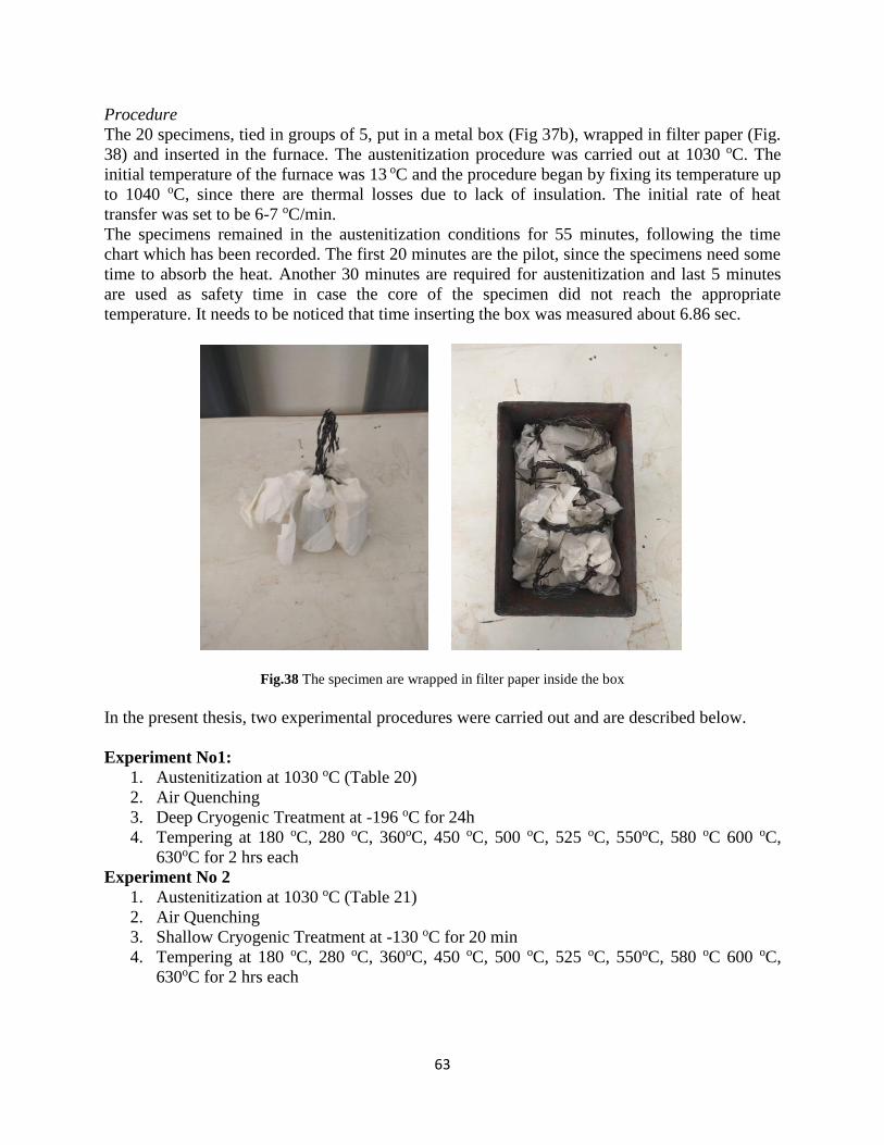
63
Procedure
The 20 specimens, tied in groups of 5, put in a metal box (Fig 37b), wrapped in filter paper (Fig.
38) and inserted in the furnace. The austenitization procedure was carried out at 1030 oC. The
initial temperature of the furnace was 13 oC and the procedure began by fixing its temperature up
to 1040 oC, since there are thermal losses due to lack of insulation. The initial rate of heat
transfer was set to be 6-7 oC/min.
The specimens remained in the austenitization conditions for 55 minutes, following the time
chart which has been recorded. The first 20 minutes are the pilot, since the specimens need some
time to absorb the heat. Another 30 minutes are required for austenitization and last 5 minutes
are used as safety time in case the core of the specimen did not reach the appropriate
temperature. It needs to be noticed that time inserting the box was measured about 6.86 sec.
Fig.38 The specimen are wrapped in filter paper inside the box
In the present thesis, two experimental procedures were carried out and are described below.
Experiment No1:
1. Austenitization at 1030 oC (Table 20)
2. Air Quenching
3. Deep Cryogenic Treatment at -196 oC for 24h
4. Tempering at 180 oC, 280 oC, 360oC, 450 oC, 500 oC, 525 oC, 550oC, 580 oC 600 oC,
630oC for 2 hrs each
Experiment No 2
1. Austenitization at 1030 oC (Table 21)
2. Air Quenching
3. Shallow Cryogenic Treatment at -130 oC for 20 min
4. Tempering at 180 oC, 280 oC, 360oC, 450 oC, 500 oC, 525 oC, 550oC, 580 oC 600 oC,
630oC for 2 hrs each
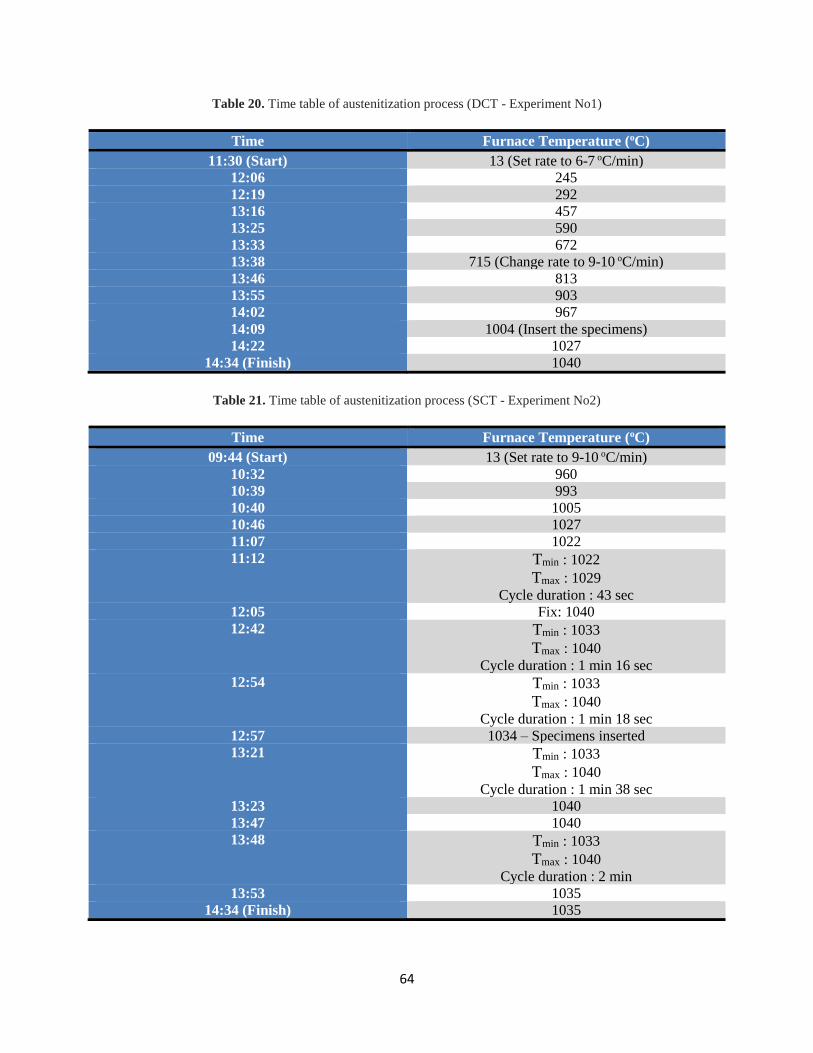
64
Table 20. Time table of austenitization process (DCT - Experiment No1)
Time Furnace Temperature (oC)
11:30 (Start) 13 (Set rate to 6-7 oC/min)
12:06 245
12:19 292
13:16 457
13:25 590
13:33 672
13:38 715 (Change rate to 9-10 oC/min)
13:46 813
13:55 903
14:02 967
14:09 1004 (Insert the specimens)
14:22 1027
14:34 (Finish) 1040
Table 21. Time table of austenitization process (SCT - Experiment No2)
Time Furnace Temperature (oC)
09:44 (Start) 13 (Set rate to 9-10 oC/min)
10:32 960
10:39 993
10:40 1005
10:46 1027
11:07 1022
11:12 Tmin : 1022
Tmax : 1029
Cycle duration : 43 sec
12:05 Fix: 1040
12:42 Tmin : 1033
Tmax : 1040
Cycle duration : 1 min 16 sec
12:54 Tmin : 1033
Tmax : 1040
Cycle duration : 1 min 18 sec
12:57 1034 – Specimens inserted
13:21 Tmin : 1033
Tmax : 1040
Cycle duration : 1 min 38 sec
13:23 1040
13:47 1040
13:48 Tmin : 1033
Tmax : 1040
Cycle duration : 2 min
13:53 1035
14:34 (Finish) 1035

65
The heat transfer process that occurs when a part is heated in a furnace is depicted in Figure.39.
Typically, the heat transfer rate is rapid initially and decreases as the temperature of the center of
the part reaches the surface temperature, which achieves the furnace temperature more rapidly.
Heat transfer in furnaces occurs by convection, radiation, and conduction.
Fig.39 Relationship of temperature rise and heating rates with respect to time
1.3.2 Stage No2: Quenching
After austenitization is completed, the specimens remain outside the furnace to cool down (Fig.
40). The exportation endured 13.19 sec. at 15:08 followed by the process of quenching. Once
the austenite is cooled below its critical temperature, it becomes unstable and transforms into
martensite. By reheating, these crystallographic and microstructural changes result in the
precipitation of finer carbides in the tempered microstructure, with consequent increase in
toughness.
Cooling rate is a function of the thickness and geometry of the sample. Moreover, it is related to
the quenching facility including the extent of agitation, racking procedure, extent of surface
oxidation, and the effective heat transfer coefficient between the part and the quenchant. In this
case, the quenchant is cold air from a blower. Following, a timetable recorded during quenching
is presented.
Table 22. Time table of quenching process (DCT - Experiment No1)
Time Quenching Temperature (oC)
15:09 (Start) 1030
15:24 65
15:28 45
15:45 (Finish) 25

66
Table 23. Time table of quenching process (DCT - Experiment No2)
Time Quenching Temperature (oC)
13:58 (Start) 1030
14:24 (Finish) 25
(a) (b)
Fig 40. (a) The box of specimens out of the furnace, (b) The specimens ready for quenching
After the process of quenching, the specimens were inserted in a secondary furnace and
maintained at 100 oC for about 1 hour, in order to achieve temporary tempering (Fig. 41). This
process is called snap tempering and is known as a precautionary interim stress-relieving
treatment applied to high hardenability steels immediately after quenching to prevent cracking.
The process started at 16:11, the temperature raised at 16:14 and thus tempering of the specimens
began. At time 17:30, the specimens were exported form the furnace and left to cool down. Their
temperature reached 40 oC at 17:49.

67
(a) (b)
Fig.41 (a) The specimens after quenching, (b) The secondary Furnace for mini tempering
1.3.3 Stage No3: Cryogenic Treatment
Liquid nitrogen is most widely used in cryogenic treatment. It has a melting point and a boiling
point of -210.01 oC (63K) and -195.8 oC (78 K), respectively. It is a most abundant gas: it
composes about four-fifths (78.03%) by volume of the atmosphere. It is often abbreviated as
LN2. It is colorless, odorless, tasteless, and nontoxic.
At the initial stage, conventional electrical cooling may also be used to reduce the temperature to
about -73 oC (200K) which makes the process economical. At -73 oC (200 K), the liquid nitrogen
system cuts in, to cool it further following a desired cycle. Liquid nitrogen is converted to a gas
before it enters the chamber, so that at no time does liquid nitrogen come in contact with the
parts to eliminate any danger of cracking of the specimen. This process refines and stabilizes the
crystal lattice structure and distributes carbon particles evenly throughout the material, creating a
stronger, more durable material. [5]
Figures 42a and 42b show the cryogenic processor of STL along with Liquid Nitrogen container.

68
(a) (b)
Fig. 42 (a) Liquid Nitrogen, (b) Chamber of Cryogenic treatment
Initially, the two main valves of nitrogen were opened. The rate of decreasing temperature
reached 2.5 oC/min, and the initial temperature was at 19 oC. When liquid nitrogen was converted
to a gas and entered the chamber, creating cryogenic conditions, specimens were inserted in the
chamber. The process endured 24 hours at temperature -196 oC.
In the end of the treatment, the final pressure reached the point of 56 PSI or 3.9 bar. Shutting off
the valves, the temperature began to increase with rate of magnitude 2.74 oC/min. The gate of the
chamber opened and the specimens were ready for cooling down until ambient temperature. The
color of the specimens, from light grey due to low temperatures, began to fade and dark metal
color was observed (Fig. 43). Below, a timetable of the procedure is exhibited.
Table. 24 Time table for Cryogenic treatment (DCT - Experiment No1)
Time Temperature oC
17:53 (Start – Open Valves) 19
18:05 -2
18:11 -20
19:18 -196
19:18 (24h – Finish) -196
19:20 -187
19:25 -178
19:30 -174
19:35 (Open the Gate) -172

69
The second experiment was carried out with the same machine and instruments. Cryogenic
treatment temperature is -130 oC with holding time of about 20 minutes, under the same
conditions regarding the cooling rate.
Table. 25 Time table for Cryogenic treatment (SCT - Experiment No2)
Time Temperature oC
16:33 (Start – Open Valves) 19
16:39 11
16:41 7
16:42 1
16:47 -6
16:52 -21
16:55 -26
16:59 -39
17:03 -51
17:05 -58
Finish (20 min) -130
(a) (b)
Fig. 43 (a) Inside the Chamber of Cryogenic treatment, (b) The specimens after the process

70
1.3.4 Stage No4: Tempering
Structural Changes [2]
Based on x-ray, dilatometric, and microstructural studies, there are three distinct stages of
tempering, even though the temperature ranges overlap:
• Stage I: The formation of transition carbides and lowering of the carbon content of the
martensite to 0.25% (100 to 250 °C, or 210 to 480 °F)
• Stage II: The transformation of retained austenite to ferrite and cementite (200 to 300 °C,
or 390 to 570 °F)
• Stage III: The replacement of transition carbides and low-temperature martensite by
cementite and ferrite (250 to 350 °C, or 480 to 660 °F)
An additional stage of tempering (stage IV), precipitation of finely dispersed alloy carbides,
exists for high-alloy steels. It has been found that stage I of tempering is often preceded by the
redistribution of carbon atoms, called autotempering or quench tempering, during quenching
and/or holding at room temperature. Other structural changes take place because of carbon atom
rearrangement preceding the classical stage I of tempering.
Dimensional Changes[2]
Martensite transformation is associated with an increase in volume. During tempering,
martensite decomposes into a mixture of ferrite and cementite with a resultant decrease in
volume as tempering temperature increases. Because a 100% martensitic structure after
quenching cannot always be assumed, volume may not continuously decrease with increasing
tempering temperature.
The retained austenite in plain carbon steels and low-alloy steels transforms to bainite with an
increase in volume, in stage II of tempering. When certain alloy steels are tempered, a
precipitation of finely distributed alloy carbides occurs, along with an increase in hardness,
called secondary hardness, and an increase in volume. With the precipitation of alloy carbides,
the Ms temperature (temperature at which martensite starts to form from austenite upon cooling)
of the retained austenite will increase and transform to martensite during cooling from the
tempering temperature. As far as the specimens are concerned, they, as pairs, are inserted in the
furnace. It is important to know that the tempering process is held in the same furnace the
austenitization happened.

71
Before placing the specimens, the bath salt of the specific Tempering Temperature was inserted
in the furnace in order to melt. When the bath salt reached expected temperature, the specimens
were inserted. The temperature of the bath salts was measured with dual input thermocouple
thermometer (Fig. 44). In Annex I and Annex II the timetables of the 20 tempering procedures
are presented.
Fig. 44 Thermometer used for the experiment

72
1.4 After Treatment
After the experiments, specimens were prepared for microstructure analysis and microhardness
measurement following the described procedure below
1.4.1 Cutting
Every one of the specimens was cut in two pieces with the follow dimensions (Fig. 46):
• One piece of 15x15x15 mm
• One piece of 25x15x15 mm
The cutting machine of Shipbuilding Technology Laboratory which was used is Discotom-5
manufactured by Struers (Fig. 45). Cutting procedure was performed with the following settings
• Propulsion speed fixed to 0.5 mm/s
• Rotational speed of disk set to 2300 RPM.
(a) (b)
Fig. 45 (a) Cutting machine outside, (b) Cutting machine inside
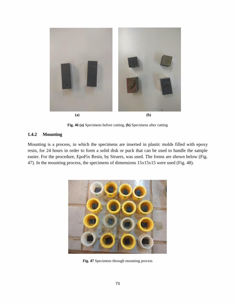
73
(a) (b)
Fig. 46 (a) Specimens before cutting, (b) Specimens after cutting
1.4.2 Mounting
Mounting is a process, in which the specimens are inserted in plastic molds filled with epoxy
resin, for 24 hours in order to form a solid disk or puck that can be used to handle the sample
easier. For the procedure, EpoFix Resin, by Struers, was used. The forms are shown below (Fig.
47). In the mounting process, the specimens of dimensions 15x15x15 were used (Fig. 48).
Fig. 47 Specimens through mounting process

74
(a) (b)
Fig. 48 (a), (b) Specimens being and numbered after mounting procedure
1.4.3 Grinding, polishing and etching
The mounted specimens were polished, in order to be used for metallographic analysis and
microhardness measurement (Fig. 50). The polishing machine is type LaboPol-5, manufactured
by Struers (Fig. 49a). The variable rotational speed of between 50 - 500 rpm is controlled by an
electronic servo system that keeps the selected speed constant, independent of the load. The
chosen speed was 300 rpm. The system is water cooled, with a 200mm in diameter platen while
sample holder can hold three specimens of 30mm. Moreover, for the procedure multiple types of
grinding papers were used, including, Grit 180, 220, 320, 500, 800, 1000, 2000. After grinding,
polishing procedure was performed by using a velvet disk with two types of polishing pastes as
lubricant, a) AP-A Suspension 1μm agglomerated alpha alumina, b) AP-A Suspension 0.3μm
agglomerated alpha alumina (Fig 49.b). Finally, nital of concentration 3-4% was used as etchant
for preparing the surface for microstructure analysis.

75
(a) (b)
Fig. 49 (a) Grinding and polishing machine LaboPol-5, (b) Polishing pastes
Fig. 50 Polished specimens

76
Section 2: Results
2.1 Microstructure
The treated samples were subjected to microstructure examination by using Leica DMIL optical
microscope coupled with Leica DFC290 HD digital microscope camera and Leica Application
Suite image analysis software. The microstructure of the material is presented in magnification
of x10, x20, x50 and x100. Microstructures were compared to the corresponding ones from the
untreated material. Figures below (Fig 51-54) show the microstructure of the specimen subjected
to tempering at 180°C and at temperatures in the precipitation area, 450°C, 500°C, 525°C and
550°C, for the two experimental procedures.
As it can be observed, the below pictures show the expected structure of martensite along with
the carbides, the density of which is noticeably increased at the temperatures around the area of
precipitation. Even though, it is argued that the cryogenic treatment contributes to complete
transformation of the retained austenite, a small percentage of remained austenite is expected to
be found [40]. The white areas are expected to be carbide areas and are dispersed inside the
matrix.
Comparing the aforementioned cryogenic treatment procedures, optical metallographic
microscope shows no difference in microstructure. Thus, SEM microscope is needed to examine
further the matrix of the samples. SEM photos are shown in the next paragraph.
Deep Cryogenic Treatment - Experiment No 1
(a) (b)
Fig. 51 Indicative microstructures of DCT (Experiment No 1) at various TT: a) Specimen No 4 – 180oC (x100), b)
Specimen No 6 – 450oC (x100)
Grain boundaries
Grain boundaries

77
(a) (b)
(c)
Fig. 52 Indicative microstructures of DCT (Experiment No 1) at various TT: a) Specimen No 8 - 500°C (x100), b)
Specimen No 12 - 525°C (x100), c) Specimen No 13 – 550°C (x100)
In the case of tempering at 180°C (Fig.51), it is observed that the microstructures after tempering
are similar with clearly etched grain boundaries. The size of the coarse grains may indicate lower
percentage of precipitated carbides inside the boundaries, in relation to the rest of the tempering
temperatures. Taking into consideration the microstructures of the TT of 500 °C, 525°C and
550°C, the grain boundaries are not clearly etched. However, carbide agglomeration areas are
observed, suggesting that microstructure is not typical tempered martensite. As TT increases, the
agglomeration of carbides becomes greater and more obvious. Moreover, fine martensite laths
and dispersed spherical carbides of Molybdenum and Vanadium (V-Cs, Mo-Cs) of size below
1μm are observed in all the above cases. The larger and wider carbides (size 1-3μm) are expected
to be the Chromium carbides (Cr-Cs). Regarding the case of shallow cryogenic treatment,
similar microstructures appear for TT of 180°C and 450°C. Nevertheless, microstructures for TT
of 500°C and 525°C show reverse results in relation to DCT. Higher levels of carbide
agglomeration are observed in the first case, suggesting increase in carbide content. For both
DCT and SCT, microstructure of tempered martensite at 550°C shows similar results.
V-Cs & Mo-Cs & Cr-Cs
Carbide agglomeration
Carbide agglomeration
Carbide agglomeration
V-Cs & Mo-Cs & Cr-Cs

78
Shallow Cryogenic Treatment - Experimental No 2
(a) (b)
(c) (d)
(e)
Fig. 53 Indicative microstructures of SCT (Experiment No 2) at various TT: a) Specimen No 21- 180°C (x100), b)
Specimen No 28 - 450°C (x100) c) Specimen No 29 - 500°C (x100), d) Specimen No 31 - 525°C (x100), e)
Specimen No 33 - 550°C (x100)
Grain boundaries
Carbide agglomeration
V-Cs & Mo-Cs & Cr-Cs
Carbide agglomeration
V-Cs & Mo-Cs & Cr-Cs
Carbide agglomeration
Grain boundaries
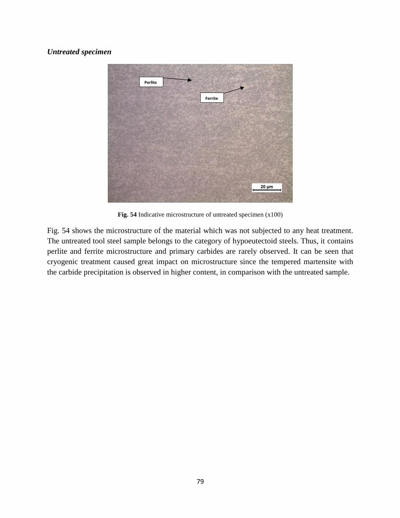
79
Untreated specimen
Fig. 54 Indicative microstructure of untreated specimen (x100)
Fig. 54 shows the microstructure of the material which was not subjected to any heat treatment.
The untreated tool steel sample belongs to the category of hypoeutectoid steels. Thus, it contains
perlite and ferrite microstructure and primary carbides are rarely observed. It can be seen that
cryogenic treatment caused great impact on microstructure since the tempered martensite with
the carbide precipitation is observed in higher content, in comparison with the untreated sample.
Perlite
Ferrite

80
2.2 Carbide Precipitation
As it has been discussed above, cryogenic treatment contributes to the formation of finer
martensite laths in the microstructure and initiates nucleation sites for precipitation of fine
carbide particles. In order to observe the precipitated carbides inside the steel matrix, scanning
electron microscope (SEM - Jeol JSM-6390), of STL was used. The SEM microscope produces
images of a sample by scanning the surface with a focused beam of electrons. The electrons
interact with atoms in the sample, producing various signals that contain information about the
sample's surface topography and composition. The following pictures exhibit the microstructure
of the H13 tool steel, including the presence of the carbides for the main tempering temperatures
(180°C, 450°C, 500°C, 525°C and 550°C).
Deep Cryogenic Treatment - Experiment No 1
• Specimen No 4 (180°C)
(a) (b)
(c)
Fig. 55 Indicative SEM microstructures of DCT (Experiment No 1) at TT=180°C: a) x10,000, b) x5,000, c) x3,000
SCs
SCs
PCs SCs
SCs
PCs
PCs
PCs
SCs
SCs

81
Carbides of various dimensions are depicted in the above photo, for tempering temperature of
180oC. The large carbide at the grain boundary is considered to be primary insoluble carbide.
Additionally, a number of carbides are portrayed in the picture, with diameter up to 0.3 μm,
which have been precipitated during tempering procedure at 180oC. It is essential to mention that
the secondary carbides at TT of 180 oC are a combination of the transition carbides (ε-carbides
and η-carbides), which were formed during tempering, and the carbides of Mo and V, which
already exist inside the matrix of the untreated tool steel. Although, the Mo-carbides and V-
carbides are part of the primal microstructure of the material, they cannot be considered as
primary carbides due to their size.
• Specimen No 6 (450°C)
(a) (b)
(c) (d)
Fig. 56 Indicative SEM microstructures of DCT (Experiment No 1) at TT=450°C: a) x10,000, b) x5,000, c) x5,000
Tempered martenisite microstructure is observed in the above photo. In contrast with the
tempering temperature of 180oC (Fig. 55), there is higher content of carbides which are more
uniformly dispersed.
SCs
SCs
PCs
SCs
SCs
SCs
SCs
SCs
PCs PCs
PCs

82
• Specimen No 8 (500°C)
Fig. 57 Indicative SEM microstructures of DCT (Experiment No 1) at TT=500°C
• Specimen No 12 (525°C)
(a) (b)
Fig. 58 Indicative SEM microstructures of DCT (Experiment No 1) at TT=525°C: a) x2,000, b) x5,000
SCs
SCs
SCs
SCs
SCs
SCs
SCs
SCs
SCs
SCs
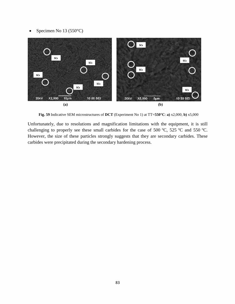
83
• Specimen No 13 (550°C)
(a) (b)
Fig. 59 Indicative SEM microstructures of DCT (Experiment No 1) at TT=550°C: a) x2,000, b) x5,000
Unfortunately, due to resolutions and magnification limitations with the equipment, it is still
challenging to properly see these small carbides for the case of 500 oC, 525 oC and 550 oC.
However, the size of these particles strongly suggests that they are secondary carbides. These
carbides were precipitated during the secondary hardening process.
SCs
SCs
SCs
SCs
SCs
SCs
SCs
SCs
SCs

84
Shallow Cryogenic Treatment - Experimental No 2
• Specimen No 21 (180°C)
(a) (b)
(c) (d)
Fig. 60 Indicative SEM microstructures of SCT (Experiment No 2) at TT=180°C: a) x10,000, b) x10,000, c)
x7,000, d) x7,000
In the above case (Fig. 60), uniform dispersion of carbides of the same size is observed. This
microstructure is similar with the one in the case of deep cryogenic treatment. In picture 60(a),
an agglomeration of carbides is observed, revealing that the thermodynamic conditions are such
as to cause the merge of two carbides. In addition, the crowded areas of carbides (Fig. 60d) show
that, despite the low TT of 180°C, the energy state of the material facilitates the initiation of the
nucleation sites for precipitation of more fine carbide particles.
SCs
SCs SCs
SCs
PCs PCs
PCs
SCs
SCs
PCs
SCs
SCs
PCs

85
• Specimen No 28 (450°C)
(a) (b)
(c) (d)
Fig. 61 Indicative SEM microstructures of SCT (Experiment No 2) at TT=450°C: a) x10,000, b) x10,000, c)
x7,000, d) x5,000
Regarding the temperature of 450°C (Fig. 61), there is uniform dispersion and the carbide
content is higher.
PCs
SCs
SCs
SCs
SCs
SCs
SCs
SCs
SCs SCs
SCs
PCs

86
• Specimen No 29 (500°C)
(a) (b)
Fig. 62 Indicative SEM microstructures of SCT (Experiment No 2) at TT=500°C: a) x10,000, b) x5,000
• Specimen No 31 (525°C)
(a) (b)
Fig. 63 Indicative SEM microstructures of SCT (Experiment No 2) at TT=525°C: a) x10,000, b) x5,000
For both of the above temperatures (Fig 62, 63), the microstructure is similar with the matrix of
the samples subjected to deep cryogenic treatment and tempered at 450 oC.
SCs
SCs
SCs
PCs
PCs
SCs
SCs
SCs
SCs
SCs

87
• Specimen No 33 (550°C)
(a) (b)
Fig. 64 Indicative SEM microstructures of SCT (Experiment No 2) at TT=550°C: a) x10,000, b) x5,000
In the particular case of shallow cryogenic treatment and tempering at 550°C, uniformly
dispersed carbides of size up to 0.3 μm are observed. These carbides are considered to be
carbides of secondary precipitation.
SCs
SCs SCs
SCs SCs
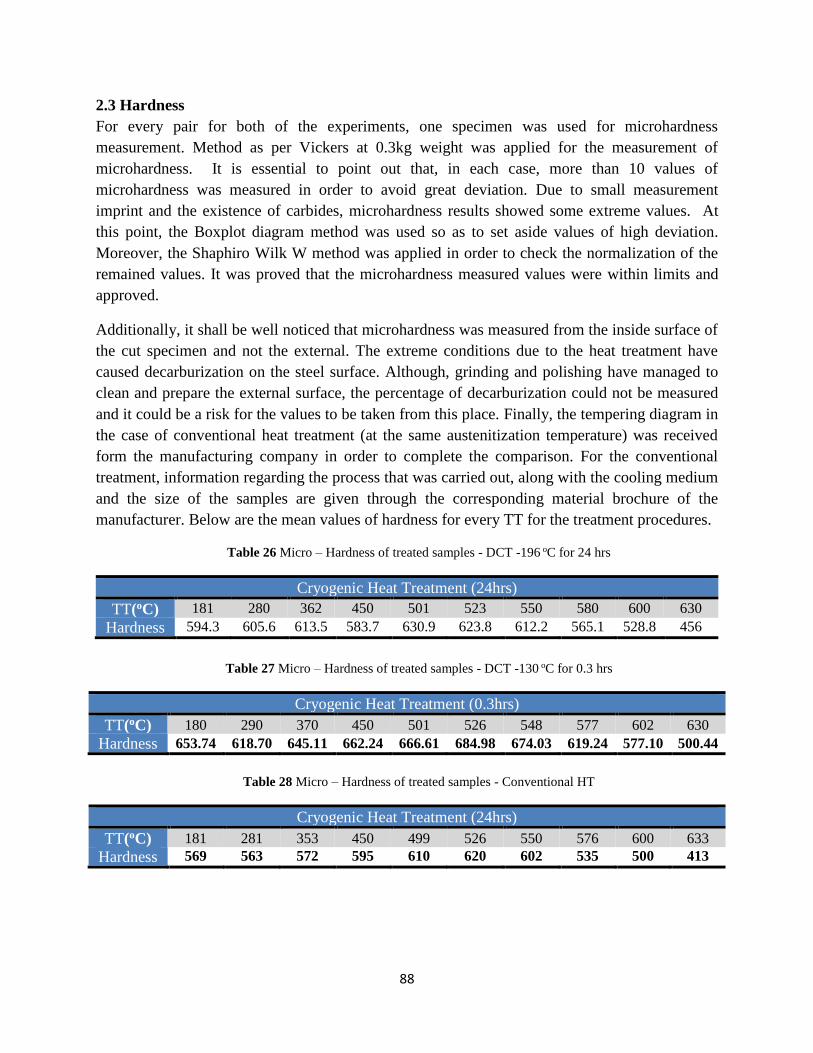
88
2.3 Hardness
For every pair for both of the experiments, one specimen was used for microhardness
measurement. Method as per Vickers at 0.3kg weight was applied for the measurement of
microhardness. It is essential to point out that, in each case, more than 10 values of
microhardness was measured in order to avoid great deviation. Due to small measurement
imprint and the existence of carbides, microhardness results showed some extreme values. At
this point, the Boxplot diagram method was used so as to set aside values of high deviation.
Moreover, the Shaphiro Wilk W method was applied in order to check the normalization of the
remained values. It was proved that the microhardness measured values were within limits and
approved.
Additionally, it shall be well noticed that microhardness was measured from the inside surface of
the cut specimen and not the external. The extreme conditions due to the heat treatment have
caused decarburization on the steel surface. Although, grinding and polishing have managed to
clean and prepare the external surface, the percentage of decarburization could not be measured
and it could be a risk for the values to be taken from this place. Finally, the tempering diagram in
the case of conventional heat treatment (at the same austenitization temperature) was received
form the manufacturing company in order to complete the comparison. For the conventional
treatment, information regarding the process that was carried out, along with the cooling medium
and the size of the samples are given through the corresponding material brochure of the
manufacturer. Below are the mean values of hardness for every TT for the treatment procedures.
Table 26 Micro – Hardness of treated samples - DCT -196 oC for 24 hrs
Cryogenic Heat Treatment (24hrs)
TT(oC) 181 280 362 450 501 523 550 580 600 630
Hardness 594.3 605.6 613.5 583.7 630.9 623.8 612.2 565.1 528.8 456
Table 27 Micro – Hardness of treated samples - DCT -130 oC for 0.3 hrs
Cryogenic Heat Treatment (0.3hrs)
TT(oC) 180 290 370 450 501 526 548 577 602 630
Hardness 653.74 618.70 645.11 662.24 666.61 684.98 674.03 619.24 577.10 500.44
Table 28 Micro – Hardness of treated samples - Conventional HT
Cryogenic Heat Treatment (24hrs)
TT(oC) 181 281 353 450 499 526 550 576 600 633
Hardness 569 563 572 595 610 620 602 535 500 413
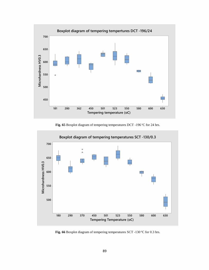
89
Fig. 65 Boxplot diagram of tempering temperatures DCT -196 oC for 24 hrs.
Fig. 66 Boxplot diagram of tempering temperatures SCT -130 oC for 0.3 hrs.
630600580550523501450362280181
700
650
600
550
500
450
Tempering temperature (oC)
Mic
roh
ard
ness
HV
0.3
Boxplot diagram of tempering tempertures DCT -196/24
630600580550523501450370290180
700
650
600
550
500
Tempering Temperature (oC)
Mic
roh
ard
ness
HV
0.3
Boxplot diagram of tempering temperatures SCT -130/0.3

90
Fig. 67 Boxplot diagram of tempering temperatures Conventional HT
According to above Boxplot diagrams (Fig. 65-67), there are extreme values of microhardness
for each of the tempering temperatures. The ones which exist far from the mean value are
considered “invalid” since they represent values of hardness in the case of carbides. As a result,
these values shall be excluded from the final chart.
It is essential to mention that the heating rate from the cryogenic temperature to ambient
temperature was studied. In the case of deep cryogenic treatment, heating rate was higher (at -
172oC, the specimens were taken out of the chamber in order to reach ambient temperature. On
the other hand, in shallow cryogenic treatment, the samples remained inside the chamber until
the expected temperature was reached.
633576550526499450353281181
750
700
650
600
550
500
Tempering temperature (oC)
Mic
roh
ard
ness
HV
0.3
Boxplot diagram of tempering temperatures Conv HT

91
Fig. 68 Comparative Tempering Chart
Shallow Cryogenic Treatment -130oC/20min
From the tempering chart (Fig 68), increase in microhardness values of 50-80HV is observed
through the temperature range, except for the area of secondary carbide precipitation where this
difference is reduced to 20-40HV. According to Uddeholm manufacturing company [31] the
difference is due to the more complete transformation of austenite into martensite, γ → α. For
lower tempering temperatures, the difference in microhardness is 1-2 HRC, whereas less or no
change is expected in the case of higher tempering temperatures. In the area of carbide
precipitation, the complete austenite transformation contributes to increasing the carbide
percentage and as a result hardness is increased. However, the difference in hardness, in the
particular area, is lower, in relation to the conventional heat treatment due to the existence of the
tempered martensite. Tempered martensite is more stable and characterized by lower hardness
than the untempered. As far as the high tempering temperatures are concerned, the difference in
microhardness between shallow cryogenic treatment and conventional treatment is greater since
there is no carbide precipitation. Additionally, no difference is observed at the temperatures of
secondary hardening between the two aforementioned heat treatments. The conditions, on which
the shallow heat treatment was carried out, such as the temperature and the duration, did not
contribute to carbide precipitation [32, 33, 34, 35]. Thus, the thermodynamic behavior of the material
did not change.
35
135
235
335
435
535
635
735
0 100 200 300 400 500 600 700
HA
RD
NE
SS
H
V0
.3
TEMPERING TEMPERATURE (OC)
ORVAR 2M:COMPARATIVE TEMPERING CHART
Conv Cryo -196/24 Cryo -130/0.3

92
Deep Cryogenic Treatment -196oC/24hrs
Regarding this type of cryogenic treatment, an increase in microhardness values of 20-40 HV is
observed, across the whole TT range, except the area of the carbide precipitation (Fig. 68). This
behavior is justified by the same reason as the ones in the case of the shallow cryogenic
treatment. Moreover, it can be observed from the chart, that the temperature, at which the carbide
precipitation takes place, is reduced by 20oC, resulting in transposition of the curve to the left.
Deep cryogenic treatment accelerates the phenomenon of diffusion and as result the precipitation
of the carbides is activated ta a lower tempering temperature. This shift is the macroscopic
representation of the change in the thermodynamic behavior of the material.
In comparison with the shallow cryogenic treatment, it can be observed that microhardness, in
the case of shallow, shows higher values than deep. This is considered to be in conflict with the
theory of microcarbide formation during the subsidence temperatures [36]. This phenomenon is
attributed to two specific reasons. One reason is related to carbon content inside the martensite
matrix [37]. The under study material contains an average percentage of carbon. As a result, the
process of carbide precipitation is restricted and there is great difficulty in observing huge
changes in hardness. However, changes in wear resistance are expected. Another reason relies on
increasing rate from the cryogenic temperature to the ambient temperature. In the case of shallow
cryogenic treatment temperature rate was slow. On the other hand, deeply cryogenically treated
samples showed higher rate of increasing temperature. According to researchers, this heating rate
plays an important role on the performance of cryogenic treatment [38]. Based on thermodynamics
rules, slow heating rate has as a result the material to pass through successive equilibrium states
in relation to the rapid rate. Thus, the final state of the material is in a different intensive state.

93
Conclusion
The present experimental thesis was carried out in order to study the changes in microstructure
and mechanical properties of Uddeholm Orvar 2M tool steel after cryogenic treatment.
According to numerous studies, cryogenic treatment on tool steels contributes to complete
transformation of retained austenite to martensite as well as precipitation and formation of finer
carbides in the material. The above microstructural changes led to enhancement of mechanical
properties of the material, including increase in hardness. The level of the changes depends on
the type of the cryogenic treatment (Deep or Shallow) and the grade of the tool steel, especially
the carbon content. Moreover, the level of contribution on the behavior of the material depends
on the sequence of the treatment processes, the quenching medium as well as the application of
additional surface treatment, such as nitriding.
Through the experimental procedure, Orvar 2M samples were subjected to deep and shallow
cryogenic treatment prior to tempering and the results were compared to the conventional heat
treatment behavior. As it was observed, both types of cryogenic treatment showed secondary
hardening in the matrix, although higher values of microhardness were measured in the case of
the shallow treatment. These results may be related to the heating rate from the cryogenic
temperature for each procedure or the carbon content of the martensitic matrix of the tool steel.
Moreover, through SEM and optical microscope, microstructure changes were observed. The
retained austenite from quenching process has not been completely transformed into martensite
and the percentage of precipitated carbides increased. The finer carbides are uniformly dispersed
inside the matrix, increasing the microhardness. It is expected that wear resistance is also
increased.
In conclusion, the present thesis gave the opportunity to understand cryogenic processing, a
subject on which a number of published papers contain conflicting or specific, generally,
conclusions and information. However, cryogenic treatment contributes in the enhancement of
mechanical properties and structure stability of the material.

94
ANNEX I
Experiment No 1 (A – Q – CT (-195/24h) – T)
Tempering Temperature = 362 oC
Specimens 1 & 2
Table A.1 Tempering at 362 oC
Time Procedure Temperature
The bathing box is
inserted in the furnace
Fix : 220 oC
Display : 276 oC
Temperature of bath: 330 oC
New Fix Fix : 320 oC
Temperature of bath: 336 oC
Cycle Tmin : 317 oC
Tmax : 338 oC
17: 52 The specimens are
inserted
Fix : 320 oC
Display : 323 oC
17:54 Check Display : 336 oC
17:56 Check Display : 329 oC (Cold material in hot environment)
18:01 Check Display : 320 oC
18:02 Check Display : 317 oC
18:03 Check Display : 330 oC
Max : 333 oC
18:05 Check Display : 331 oC
18:05 Cycle
Tmin : 317 oC
Tmax : 333 oC
Cycle duration : 12 min 18 sec
18:36 Check Display : 318 oC
18:37 Check Display : 317 oC (Re: ON)
18:49 Check Display : 324 oC
18:51 Check Display : 334 oC
18:55 Check Display : 326 oC
19:01 Check Display : 317 oC
19:02 Check
Fix : 320 oC
Display : 333 oC
Temperature of bath: 363 oC
19:02 Check
Tmin : 317 oC
Tmax : 333 oC
(10,44 min)
20:02 END of Tempering Temperature of bath: 362 oC
20:03 Cooling
20:09 END T: 30 oC

95
Tempering Temperature = 180 oC
Specimens 3 & 4
Table A.2 Tempering at 180 oC
Time Procedure Temperature
The bathing box is
inserted in the furnace
Fix : 220 oC
Display : 218 oC
Temperature of bath: 264 oC
New Fix
Fix : 170 oC
Display : 218 oC
Temperature of bath: 246 oC
New Fix Fix : 150 oC
18:28 Check
Fix : 150 oC
Display : 189 oC
Temperature of bath: 221 oC
18:48 Check
Fix : 120 oC
Display : 158 oC
Temperature of bath: 204 oC
19:06 Check
Fix : 130 oC
Display : 147 oC
Temperature of bath: 198oC
19:22 New Fix Fix : 100 oC
Temperature of bath: 184oC
19:30 Check
Fix : 100 oC
Display : 145 oC
Temperature of bath: 181oC
19:33 New Fix Fix : 135 oC
19:40 Check Display : 142 oC
Temperature of bath: 183oC
19:40 New Fix Fix : 130 oC
19:40 The specimens are
inserted
19:47 Check Display : 149 oC
19:57 Check Fix : 135 oC
Display : 146 oC
20:12 New Fix Fix : 140 oC
Display : 143 oC
20:38 Check
Fix : 140 oC
Display : 135 oC
Temperature of bath: 183oC
20:54 Check Display : 155 oC
21:08
21:16 Check
Display : 149 oC
Display : 147 oC
21:18 Check Display : 140 oC
Temperature of bath: 185oC
21:32 Check Display : 141 oC
21:38 Check Display : 140 oC
21:47 END of Tempering Display : 139 oC
Temperature of bath: 183oC

96
Tempering Temperature = 450 oC
Specimens 5 & 6
Table A.3 Tempering at 450 oC
Time Procedure Temperature
The Furnace is ON Fix : 415 oC
Rate : 7-8 oC/min
The specimens are
inserted
18:38 Check Display : 426 oC
Temperature of bath: 440oC
19:09 Cycle
Tmin : 412 oC
Tmax : 425 oC
Cycle duration : 8 min 14 sec
19:45 Check
Fix : 415 oC
Display : 424 oC
Temperature of bath: 448oC
20:38 Check
Fix : 415 oC
Display : 415 oC
Temperature of bath: 449oC
20:38 END of Tempering
20:39 Cooling
20:50 END

97
Tempering Temperature = 500 oC
Specimens 7 & 8
Table A.4 Tempering at 500 oC
Time Procedure Temperature
09:46 The Furnace is ON Fix : 465 oC
Rate : 6-7 oC/min
10:04 Check Display : 306 oC
10:08 New Rate Rate : 9-10 oC/min
10:23 Check Display : 459 oC (Re : ON)
Display : 461 oC (Re : OFF)
10:25 Cycle T: 462 oC(Re : ON) T: 464 oC(Re : OFF) (38.7 sec)
10:28 Check Display : 468 oC
10:28 Cycle
Tmin : 462 oC
Tmax : 469 oC
Cycle duration : 2 min 26 sec
10:33 Check Display : 469 oC
Temperature of bath: 371oC
10:54 Check Display : 468 oC
10:59 Cycle
Tmin : 462 oC
Tmax : 473 oC
Cycle duration : 3 min 55 sec
11:26 Check Temperature of bath: 482oC
11:37 Check
Fix : 465 oC
Display : 466 oC
Temperature of bath: 486oC
11:53 Check Temperature of bath: 488oC
12:16 Check Temperature of bath: 493oC
12:40 Check – New Fix Temperature of bath: 493oC
Fix : 470 oC
13:07 New Fix Fix : 480 oC
Display : 488 oC
13:09 The specimens are
inserted
Fix : 480 oC
Display : 482 oC
Temperature of bath: 501oC
13:32 Check Display : 477 oC
13:50 Cycle
Tmin : 476 oC
Tmax : 489 oC
Cycle duration : 5 min 52 sec
14:30 Check Display : 476 oC (Re : ON)
Display : 481 oC (Re : OFF)
14:32 Check Display : 489 oC (MAX)
14:56 Check Fix : 480 oC
Display : 492 oC
Temperature of bath: 507oC
15:10 END of Tempering
15:16 Cooling
15:21 END

98
Tempering Temperature = 280 oC
Specimens 9 & 10
Table A.5 Tempering at 280 oC
Time Procedure Temperature
08:50
The Furnace is ON - The
bath salts for 280 oC, 350
oC are inserted
09:10 Check
Fix : 230 oC
Rate : 6-7 oC/min
Display : 85 oC
09:32 Check Display : 204 oC
09:39 New Fix Fix : 230 oC
Display : 225 oC
09:42 New Fix Fix : 240 oC
09:59 New Fix Fix : 260 oC
Display : 271 oC
10:05 Liquefaction of bath
10:06 Check Display : 257 oC (Re : ON)
10:07 Check Display : 262 oC (Re : OFF)
10:16 Check Display : 257 oC (Re : ON)
Display : 262 oC (Re : OFF)
10:23 Check Display : 273 oC (MAX)
10:52 Full Liquefaction of bath
11:10 Check – New Fix – new
Rate
Temperature of bath: 230oC
Fix : 290 oC
Rate : 10 oC/min
11:14 Check Display : 309 oC
11:23 Cycle
Tmin : 287 oC
Tmax : 301 oC
Cycle duration : 5 min 26 sec
11:33 Check Temperature of bath: 260oC
11:34 New Fix Fix : 310 oC
12:22 Check – New Fix Temperature of bath: 330oC
Fix : 260 oC
13:10 Check Temperature of bath: 316oC
13:20 New Fix Fix : 225 oC
13:55 Check - The door of
Furnace is opened Temperature of bath: 302oC
14:03 Check - The door of
Furnace is closed Display : 197 oC
14:24 Check Fix : 225 oC
Display : 232 oC
Temperature of bath: 283oC
14:40 The specimens are
inserted
Fix : 225 oC
Display : 232 oC
Temperature of bath: 280oC
15:02 Check Fix : 225 oC

99
Display : 229 oC
15:14 Check Display : 225 oC
15:24 Check Display : 222 oC (Re : ON)
Display : 226 oC (Re : OFF)
15:24 Cycle
Tmin : 222 oC
Tmax : 240 oC
Cycle duration : 27 min 9 sec
16:25 Check Temperature of bath: 270oC
16:42 END of Tempering
16:43 Cooling
16:47 END

100
Tempering Temperature = 525 oC
Specimens 11 & 12
Table A.6 Tempering at 525 oC
Time Procedure Temperature
09:53 The Furnace is ON
Fix : 490 oC
Rate : 7-8 oC/min
Display : 498 oC
09:56 Cycle
Tmin : 486 oC
Tmax : 498 oC
Cycle duration : 4 min 29 sec
10:20 Check Display : 486 oC (Re : ON)
10:27 Check Display : 495 oC
10:42 Check Display : 498 oC (MAX)
10:51 Cycle
Tmin : 486 oC
Tmax : 498 oC
Cycle duration : 5 min 11 sec
10:56 Check
Fix : 490 oC
Display : 490 oC
Temperature of bath: 513oC
Rate : 7-8 oC/min
11:56 Check
Fix : 490 oC
Display : 498 oC
Temperature of bath: 517oC
11:56 New Fix Fix = 495 oC
12:05 Cycle
Tmin : 491 oC
Tmax : 503 oC
Cycle duration : 5 min 35 sec
12:13 Check Temperature of bath: 521oC
12:59 Check Fix : 495 oC
Display : 503 oC
13:10 Check Temperature of bath: 522oC
13:37 The specimens are
inserted
Temperature of bath: 523oC
13:55 Check Fix : 495 oC
Display : 497 oC
13:55 Cycle
Tmin : 491 oC
Tmax : 504 oC
Cycle duration : 6 min 52 sec
15:04 Check Display : 494 oC
15:14 Check Display : 504 oC
15:27 Check Display : 491 oC (Re : ON)
15:30 Check Fix : 495 oC
Display : 500 oC
Temperature of bath: 525oC
15:37 END of Tempering
15:38 Cooling
15:46 END

101
Tempering Temperature = 550 oC
Specimens 13 & 14
Table A.7 Tempering at 550 oC
Time Procedure Temperature
09:52 The Furnace is ON Fix : 520 oC
Rate : 7-8 oC/min
11:41 Check Display : 520 oC
11:43 Check Display : 531 oC
11:43 Cycle
Tmin : 517 oC
Tmax : 529 oC
Cycle duration : 6 min 58 sec
12:04 Check
Fix : 520 oC
Display : 518 oC
Temperature of bath: 550oC
12:08 The specimens are
inserted
12:50 Check Display : 519 oC
12:50 Cycle
Tmin : 517 oC
Tmax : 529 oC
Cycle duration : 6 min 51 sec
13:00 Check Display : 527 oC
Fix : 520 oC
13:36 Check Fix : 520 oC
Display : 524 oC
13:45 Check Fix : 520 oC
Display : 517 oC (Re : ON)
13:55 Check Fix : 520 oC
Display : 524 oC
14:02 Check
Fix : 520 oC
Display : 529 oC
Temperature of bath: 551oC
14:08 END of Tempering
14:09 Cooling
14:15 END

102
Tempering Temperature = 580 oC
Specimens 15 & 16
Table A.8 Tempering at 580 oC
Time Procedure Temperature
09:41 The Furnace is ON
Fix : 550 oC
Display : 498 oC
Rate : 7-8 oC/min
10:01 Check Fix : 550 oC
Display : 548 oC
10:09 Cycle
Tmin : 546 oC
Tmax : 553 oC
Cycle duration : 2 min 20 sec
10:23 Check Fix : 550 oC
Display : 546 oC (Re : ON)
10:34 Check Display : 552 oC
Temperature of bath: 566oC
10:47 Cycle
Tmin : 546 oC
Tmax : 557 oC
Cycle duration : 3 min 20 sec
12:02 Check
Fix : 550 oC
Display : 547 oC
Temperature of bath: 569oC
12:02 New Fix - New Rate Fix : 560 oC
Rate : 8-9 oC/min
12:20 Cycle
Tmin : 556 oC
Tmax : 567 oC
Cycle duration : 4 min 12 sec
12:40 The specimens are
inserted
Fix : 560 oC
Display : 558 oC
Temperature of bath: 580oC
13:00 Check Fix : 560 oC
Display : 563 oC
13:10 Check Fix : 560 oC
Display : 567 oC
13:34 Cycle
Tmin : 556 oC
Tmax : 568 oC
Cycle duration : 4 min 54 sec
14:22 Check Fix : 560 oC
Display : 568 oC
14:33 Check
Fix : 560 oC
Display : 567 oC
Temperature of bath: 585oC
14:43 END of Tempering
Fix : 560 oC
Display : 564 oC
Temperature of bath: 585oC
14:44 Cooling
14:52 END

103
Tempering Temperature = 600 oC
Specimens 17 & 18
Table A.9 Tempering at 600 oC
Time Procedure Temperature
The Furnace is ON Fix : 580 oC
Rate : 9-10 oC/min
17:42 The specimens are
inserted
Fix : 580 oC
Display : 582 oC
17:42 Cycle
Tmin : 576 oC
Tmax : 586 oC
Cycle duration : 5 min 12 sec
17:42 Cycle
Tmin : 412 oC
Tmax : 425 oC
Cycle duration : 5 min 20 sec
19:47 Cycle
Tmin : 412 oC
Tmax : 425 oC
Cycle duration : 5 min 15 sec
19:47 Check Fix : 580 oC
Temperature of bath: 603oC
19:47 END of Tempering
14:48 Cooling
14:55 END

104
Tempering Temperature = 630 oC
Specimens 19 & 20
Table A.10 Tempering at 630 oC
Time Procedure Temperature
09:34 The Furnace is ON Fix : 650 oC
Rate : 9-10 oC/min
11:08 Open the door – New Fix Fix : 600 oC
Temperature of bath: 657oC
11:12
Close the door
Fix : 600 oC
Display : 570 oC
11:23 Check Fix : 600 oC
Display : 607 oC
11:23 Cycle
Tmin : 596 oC
Tmax : 607 oC
Cycle duration : 4 min 37 sec
11:52 Check – New Fix
Fix : 610 oC
Display : 600 oC
Temperature of bath: 615oC
12:03 Check Fix : 610 oC
Display : 613 oC
12:03 Cycle
Tmin : 606 oC
Tmax : 616 oC
Cycle duration : 3 min 31 sec
12:17 Check Fix : 610 oC
Display : 616 oC
12:25 Check
Fix : 610 oC
Display : 615 oC
Temperature of bath: 627oC
12:30 The specimens are
inserted
13:07 Check Fix : 610 oC
Display : 610 oC
13:07 Cycle
Tmin : 606 oC
Tmax : 617 oC
Cycle duration : 4 min 15 sec
14:06 Check Fix : 610 oC
Display : 607 oC
14:24 Check
Fix : 610 oC
Display : 608 oC
Temperature of bath: 632oC
14:30 END of Tempering
14:31 Cooling
14:40 END

105
ANNEX II
Experiment No 2 (A – Q – CT (-130/20m) – T)
Tempering Temperature = 180 oC
Specimens 21 & 22
Table A.11 Tempering at 180 oC
Time Procedure Temperature
09:44 Furnace is ON Fix : 120 oC
Rate : 7-8 oC/min
09:52 Check-New rate
Fix : 120 oC
Display : 61oC
Rate : 9-10 oC/min
09:57 Bath of 190 oC is
inserted
10:13 Check Fix : 120 oC
Display : 133 oC
10:22 Cycle
Tmin : 118 oC
Tmax : 137 oC
Cycle duration : 11 min 33 sec
10:35 New Fix New Fix : 220 oC
Display : 119 oC
11:28 Check Fix : 220oC
Display : 226 oC
Cycle
Tmin : 217 oC
Tmax : 234 oC
Cycle duration : 8 min 29 sec
12:10 Check – New Fix
Display : 228 oC
Temperature of bath: 211oC
New Fix : 200 oC
12:30 New Fix Fix : 150 oC
13:50 Check Fix : 150 oC
Display : 187 oC
13:35 New Fix – Open door Fix : 130 oC
14:20 Check Fix : 130 oC
Temperature of bath: 180oC
The specimens are
inserted
15:00 Check Display : 150 oC
15:25 Check Fix : 130 oC
Display : 143 oC
15:44 Check Fix : 140 oC
Display : 136 oC
16:07 Check Display : 135 oC
16:20 END of Tempering Display : 134 oC
Temperature of bath: 180oC
16:26 Cooling
16:31 END

106
Tempering Temperature = 290 oC
Specimens 23 & 24
Table A.12 Tempering at 290 oC
Time Procedure Temperature
09:21
The Furnace is ON - The
bath salts for 190 oC is
inserted
Fix : 290 oC
Rate : 9-10 oC/min
09:41 Check Fix : 230 oC
Display : 295 oC
09:59 Check Display : 286 oC
10:31 Cycle
Tmin : 286 oC
Tmax : 302 oC
Cycle duration : 6 min 52 sec
10:40 Check
Fix : 290 oC
Display : 289 oC
Temperature of bath: 274oC
10:45 Cycle
Tmin : 286 oC
Tmax : 302 oC
Cycle duration : 6 min 58 sec
10:57 Check Display : 294 oC (Re : ON)
11:07 Check Display : 291 oC
Temperature of bath: 300oC
11:11 New fix – Open door Fix : 270 oC
11:47 Check Fix : 270 oC
Temperature of bath: 272oC
12:08 Cycle
Tmin : 267 oC
Tmax : 284 oC
Cycle duration : 11 min 7 sec
12:24 New Fix - Open Door Fix : 260 oC
Rate : 9-10 oC/min
12:30 Check Temperature of bath: 283oC
12: 30 Specimen are inserted
13:22 Check Display : 263 oC
Cycle
Tmin : 257 oC
Tmax : 275 oC
Cycle duration : 17 min 59 sec
13:56 Check Fix : 260 oC
Display : 266oC
Cycle Tmin : 257oC
Tmax : 275 oC
Cycle duration : 18 min 3 sec
14:25 Check Temperature of bath: 290oC
14:30 END of Tempering
14:31 Cooling
14:36 END

107
Tempering Temperature = 370 oC
Specimens 25 & 26
Table A.13 Tempering at 370 oC
Time Procedure Temperature
14:38
The bathing box of 290
oC is inserted in the
furnace
Fix : 330 oC
Rate : 9-10 oC/min
15:08 Check Display : 329 oC
15:30 Cycle
Tmin : 326oC
Tmax : 342 oC
Cycle duration : 5 min 38 sec
15:43 Check Display : 334 oC
16:00 Check – New Fix Temperature of bath: 288oC
New Fix : 340 oC
16:19 Cycle
Tmin : 336oC
Tmax : 353 oC
Cycle duration : 8 min 51 sec
16:45 Check Fix : 340 oC
Temperature of bath: 355oC
16:45 The specimen are
inserted
17:21 Cycle
Tmin : 336oC
Tmax : 353 oC
Cycle duration : 11 min 55 sec
18:09 Check Display : 344 oC
Cycle
Tmin : 336oC
Tmax : 353 oC
Cycle duration : 12 min 21 sec
18:40 Check Temperature of bath: 370 oC
18:45 END of Tempering
18:46 Cooling
18:54 END

108
Tempering Temperature = 450 oC
Specimens 27 & 28
Table A.14 Tempering at 450 oC
Time Procedure Temperature
09:41 The Furnace is ON Fix : 410 oC
Rate : 9-10 oC/min
10:29 Check Display : 415 oC
Temperature of bath: 361oC
10:56 Check Display : 412 oC
Temperature of bath: 412oC
11:09 Cycle
Tmin : 407 oC
Tmax : 421 oC
Cycle duration : 5 min 54 sec
11:35 Check Fix : 410 oC
Temperature of bath: 434oC
12:51 Check Fix : 410 oC
Temperature of bath: 445oC
The specimen are
inserted
14:07 Check Display : 412 oC
14:28 Cycle
Tmin : 407 oC
Tmax : 422 oC
Cycle duration : 9 min 14 sec
14:43 Check Temperature of bath: 444oC
15:51 END of Tempering
14:53 Cooling
15:00 END

109
Tempering Temperature = 500 oC
Specimens 29 & 30
Table A.15 Tempering at 500 oC
Time Procedure Temperature
15:05 The Furnace is ON Fix : 450 oC
Rate : 9-10 oC/min
15:32 Check Display : 460 oC
Temperature of bath: 474oC
15:51 Cycle
Tmin : 447 oC
Tmax : 461 oC
Cycle duration : 7 min 35 sec
Check Temperature of bath: 480oC
16:20 Check – New Fix Temperature of bath: 481oC
New Fix : 460 oC
16:53 Check Temperature of bath: 490oC
17:17 New Fix Fix : 470 oC
17:41 Check Temperature of bath: 500oC
The specimen are
inserted
18:07 Check Display : 480 oC
18:36 Cycle
Tmin : 467 oC
Tmax : 480 oC
Cycle duration : 7 min 48 sec
19:21 Cycle
Tmin : 467 oC
Tmax : 480 oC
Cycle duration : 7 min 53 sec
19:35 Check Display : 501 oC
19:41 END of Tempering
19:42 Cooling
19:45 END

110
Tempering Temperature = 525 oC
Specimens 31 & 32
Table A.16 Tempering at 525 oC
Time Procedure Temperature
09:31 The Furnace is ON Fix : 490 oC
Rate : 9-10 oC/min
10:15 Check Display : 490 oC
10:15 Cycle
Tmin : 486 oC
Tmax : 496 oC
Cycle duration : 2 min 49 sec
12:09 Check – New Fix Temperature of bath: 515oC
New Fix : 500 oC
12:34 Check Temperature of bath: 521oC
12:40 Cycle
Tmin : 497 oC
Tmax : 509 oC
Cycle duration : 2 min 49 sec
Cycle
Tmin : 486 oC
Tmax : 498 oC
Cycle duration : 5 min 30 sec
12:51 Check Temperature of bath: 524oC
The specimen are
inserted
14:03 Check Display : 500 oC
Cycle
Tmin : 497 oC
Tmax : 510 oC
Cycle duration : 6 min 19 sec
14:45 Check Temperature of bath: 526oC
14:51 END of Tempering
14:52 Cooling
14:59 END

111
Tempering Temperature = 550 oC
Specimens 33 & 34
Table A.17 Tempering at 550 oC
Time Procedure Temperature
09:27 The Furnace is ON Fix : 520 oC
Rate : 9-10 oC/min
10:46 Check
Fix : 520 oC
Display : 518 oC
Temperature of bath: 550oC
11:03 Cycle
Tmin : 517 oC
Tmax : 528 oC
Cycle duration : 4 min
11:16 Check Temperature of bath: 537oC
12:01 Check – New Fix Temperature of bath: 540oC
New Fix : 525 oC
12:41 Check Temperature of bath: 548oC
12:42 The specimens are
inserted
13:57 Cycle
Tmin : 522 oC
Tmax : 534 oC
Cycle duration : 5 min 25 sec
14:38 Check Temperature of bath: 547oC
14:42 END of Tempering
14:43 Cooling
14:51 END

112
Tempering Temperature = 580 oC
Specimens 35 & 36
Table A.18 Tempering at 580 oC
Time Procedure Temperature
09:30 The Furnace is ON Fix : 550 oC
Rate : 9-10 oC/min
10:30 Check Fix : 550 oC
Display : 555 oC
10:49 Check Display : 574oC
Cycle
Tmin : 546 oC
Tmax : 557 oC
Cycle duration : 3 min 20 sec
11:14 Check Fix : 550 oC
Temperature of bath: 574oC
11:28 Cycle
Tmin : 547 oC
Tmax : 558 oC
Cycle duration : 4 min 3 sec
11:56 Check Temperature of bath: 577oC
The specimens are
inserted
13:02 Cycle
Tmin : 552 oC
Tmax : 563 oC
Cycle duration : 4 min 47 sec
13:32 Cycle
Tmin : 552 oC
Tmax : 563 oC
Cycle duration : 4 min 57 sec
13:49 Check Fix : 560 oC
Temperature of bath: 577oC
13:56 END of Tempering
13:57 Cooling
14:01 END
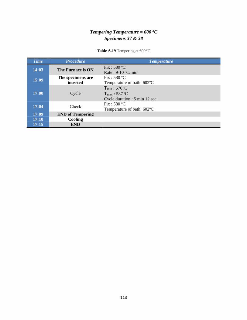
113
Tempering Temperature = 600 oC
Specimens 37 & 38
Table A.19 Tempering at 600 oC
Time Procedure Temperature
14:03 The Furnace is ON Fix : 580 oC
Rate : 9-10 oC/min
15:09 The specimens are
inserted
Fix : 580 oC
Temperature of bath: 602oC
17:00 Cycle
Tmin : 576 oC
Tmax : 587 oC
Cycle duration : 5 min 12 sec
17:04 Check Fix : 580 oC
Temperature of bath: 602oC
17:09 END of Tempering
17:10 Cooling
17:15 END

114
Tempering Temperature = 630 oC
Specimens 39 & 40
Table A.20 Tempering at 630 oC
Time Procedure Temperature
11:39 The Furnace is ON Fix : 600 oC
Rate : 9-10 oC/min
12:16 Check Fix : 600 oC
Display : 600 oC
Cycle
Tmin : 596 oC
Tmax : 604 oC
Cycle duration : 2 min 5 sec
13:07 Check Fix : 600 oC
Temperature of bath: 614oC
13:39 Cycle
Tmin : 596 oC
Tmax : 606 oC
Cycle duration : 3 min 28 sec
13:44 Check – New Fix Temperature of bath: 618oC
New Fix : 605 oC
14:14 Check Fix : 605 oC
Display : 604 oC
Cycle
Tmin : 601 oC
Tmax : 611 oC
Cycle duration : 4 min 2 sec
14:26 Check Fix : 605 oC
Temperature of bath: 626oC
14:27 The specimens are
inserted
16:09 Check Fix : 605 oC
Display : 607 oC
16:11 Cycle
Tmin : 601 oC
Tmax : 612 oC
Cycle duration : 4 min 27 sec
Cycle
Tmin : 601 oC
Tmax : 612 oC
Cycle duration : 4 min 26 sec
16:22 Check Fix : 610 oC
Temperature of bath: 626oC
16:27 END of Tempering
16:28 Cooling
16:33 END

115
References
1. ASM Handbook Committee (2005), ASM Handbook, Volume 1, Properties and
Selection: Irons, Steels, and High Performance Alloys, ASM International,(2005),
ISBN-10: 0871703777, USA, , p. 233-250, p. 708-731, p. 1165-1175
2. ASM Handbook Committee (1991), ASM Handbook Vol 4: Heat Treating, ASM, 1991,
ISBN-10: 0871703793, USA, p. 102-294, p. 487, p. 1544-1589, p. 1162,
3. Bohler-Uddeholm (2013), H13Tool Steel, Bohler-Uddeholm Materialize Visions
4. Klaus D. Timmerhaus, Thomas M. Flynn (1989), Cryogenic Process Engineering,
International Cryogenics Monograph Series, Springer, 1989, USA, p. 16-18
5. Nirmal S. Kalsi, Rakesh Sehgal, and Vishal S. Sharma(2010), Cryogenic Treatment of
Tool Materials: A Review, Taylor & Francis Group, LLC, ISSN: 1042-6914,2010, UK, p.
6, p. 1077-1096
6. Klaus D. Timmerhaus and Richard P. Reed (2007), Cryogenic Engineering: Fifty Years
of Progress, Springer Science+Business Media, LLC, 2007, USA, p. 19-25
7. D. Mohan Lal, S. Renganarayanan, A. Kalanidhi, (2001), Cryogenic treatment to
augment wear resistance of tool and die steels, Elsevier Ltd , 2001, p. 149-155
8. Zbigniew Latas, Aleksander Ciski, Pavel Suchmann Comtes Fht s.r.o., (2006) Cryogenic
Treatment and Combination of Nitriding and Cryogenic Treatment of Hot Forging
Tools, Cryogenics, 4th WSEAS Int. Conf , 2006, Greece, p. 133-139
9. B. Podgornik, I. Paulina, B. Zajecb, S. Jacobsonc, V. Leskovˇsek (2015), Deep
cryogenic treatment of tool steels, Journal of Materials Processing Technology, Elsevier
Ltd , 27 September 2015, p. 398-406
10. Mahdi Koneshlou, Kaveh Meshinchi Asl, Farzad Khomamizadeh (2010) Effect of
cryogenic treatment on microstructure, mechanical and wear behaviors of AISI H13
hot work tool steel, Cryogenics , Elsevier Ltd, 1 November 2010, p. 55-61
11. A. Akhbarizadeh , A. Shafyei, M.A. Golozar (2008), Effects of cryogenic treatment on
wear behavior of D6 tool steel, Materials and Design, Elsevier Ltd, 2008, Department of
Materials Engineering, Isfahan University of Technology, Iran, p. 3259-3264
12. Sanjeev Katoch, Rakesh Sehgal, Vishal Singh (2014), Effect of Cryogenic Treatment on
Hardness, Microstructure and Wear Behavior of Hot Die Steel Grade AISI-H13,
Springer, 2014, India, p. 159-166
13. X.G. Yan, D.Y.Li, (2013), Effects of the sub-zero treatment condition on
microstructure, mechanical behavior and wear resistance of W9Mo3Cr4V high speed
steel, Wear, Elsevier B.V., 2013, China, p. 854-862
14. J.R. Davis (1998), ASM Specialty Handbook Carbon and Alloy Steels, ASM, ISBN:
978-0-87170-557-0, 1998, USA, p. 3-12
15. William E. Bryson (2009), Heat Treatment, Selection, and Application of Tool Steels
2nd Edition, Carl Hanser Verlag/ Hanser Publications, ISBN 1-56990-376-X 2009,
Germany, p. 17-35
16. West Yorkshire Steel, H13 Tool Steel, West Yorkshire Steel Co Ltd, UK

116
17. Shaohong Li, Yinzi Xie, Xiaochun Wu , (2010), Hardness and Toughness
investigations of deep cryogenic treated cold work die steel, Cryogenics, Elsevier B.V.,
2010, China, p. 89-92
18. Debdulal Das, Rajdeep Sarkarb, Apurba Kishore Dutta, Kalyan Kumar Ray, (2010),
Influence of sub-zero treatments on fracture toughness of AISI D2 steel, Materials
Science and Engineering A , Elsevier B.V., 2010, India, p. 589-603
19. A.I. Tyshchenko,W. Theisen, A. Oppenkowski, S. Siebert, O.N. Razumov, A.P. Skoblik,
V.A. Sirosha, Yu.N. Petrov, V.G. Gavriljuk , (2010), Low-temperature martensitic
transformation and deep cryogenic treatment of a tool steeL, Materials Science and
Engineering A, Elsevier B.V., 2010, p. 7027-7039
20. Wikipedia «Tool Steels»
21. J.Y. Huang, Y.T. Zhu, X.Z. Liao, I.J. Beyerlein, M.A. Bourke, T.E. Mitchell(2003),
Microstructure of cryogenic treated M2 tool steel, Materials Science and Engineering A,
Materials Science and Technology Division, Los Alamos National Laboratory, Elsevier
B.V., 2003, USA, p. 241-244
22. Seyed Ebrahim Vahdat , Saeed Nategh, Shamsoddin Mirdamadi (2013), Microstructure
and tensile properties of 45WCrV7 tool steel after deep cryogenic treatment, Materials
Science and Engineering A , Department of Materials Engineering, Isfahan University of
Technology, Elsevier B.V., 2013, India, p. 444-454
23. Flavio J. da Silva, Sinesio D. Franco, Alisson R. Machado, Emmanuel O. Ezugwu,
Antonio M. Souza Jr. (2006), Performance of cryogenically treated HSS tools, Wear,
Elsevier B.V., 2006, p. 674-685
24. George Kraus (2005), Steels: Processing, Structure, and Performance (2nd Ed), ASM
International, Materials Park (OH), 2005, USA, p. 384-385, p. 637-638
25. Karl-Erik Thelning (1984), Steel and its heat treatment, Second edition, Butterworth-
Heinemann, ISBN 0 408 01424 5, 1984, Sweden, p. 355-368
26. George E. Totten, Ph.D., FASM (2007), Steel Heat Treatment Handbook: Equipment
and Process Design, Taylor & Francis Group, LLC, ISBN-10: 0-8493-8454-0, 2007,
USA, p. 7-13
27. Debdulal Das, Rajdeep Sarkarb, Apurba Kishore Dutta, Kalyan Kumar Ray (2010), Sub-
zero treatments of AISI D2 steel: Part I. Microstructure and hardness, Materials
Science and Engineering A, Elsevier B.V., 2010, p. 2182-2193
28. George Roberts, George Krauss, Richard Kennedy (2005), Tool Steels: 5th Edition,
ASM International , 1998, USA, p. 212-244
29. Marcos Pérez, Francisco Javier Belzunce (2014), The effect of deep cryogenic
treatments on the mechanical properties of an AISI H13 steel, Materials Science and
Engineering A, Materials Science & Engineering A, Elsevier B.V, 2014, p. 32-40
30. Cord Henrik Surberg, Paul Stratton, Klaus Lingenhole (2010), The effect of some heat
treatment parameters on the dimensional stability of AISI D2, Cryogenics, Elsevier
B.V., 2010, p. 42-47

117
31. Uddeholms AB, Heat treatment of Uddeholm tool steels (2017), Edition 9, 2018,
Germany, p.4-18
32. Meng F.,Tagashira K., Azuma R., Sohma H. (1994), Role of Eta-carbide Precipitations
in the Wear Resistance Improvements of Fe-12Cr-Mo-V-1.4C Tool Steel by Cryogenic
Treatment ,ISIJ Int 34 (1994), p. 205-210
33. Yen, P.L., Kamody, D.J. Formation of Fine Eta Carbides in Special Cryogenic and
Tempering Process Key to Improved Properties of Alloy Steels, Ind. Heat., Vol. 64,
1997, p. 40–44.
34. M.J. Van Cenderen, A. Böttger, R.J. Cernik, E.J. Mittemeijer, Metall. Trans. A 24
(1993), p. 1965-1973
35. Gogte C.L.,Kumar M.I., Paretkar R.K in: M. Rosso, M Actis Grande, Urgues D. (Eds),
Proceedings of the 7th International Tooling Conference, Politechnico di Torino,
Torino, Italy, May 2-5, 2006, p. 151-158.
36. Mohan Lal D., Renganarayanan S., Kalanidhi A., Cryogenics 41 (2001), p. 149-155
37. Hirotsu Y., Nagakura S., Acta Metall. Vol 20 (1972), p. 645-655
38. Oppenkowski A., Weber S., Theisen W, J. Mater. Process. Tech 210 (2010), p. 1949-
1955
39. Kokosza A., Pacyna J., Proceedings of the 13th ISCAMME (2005), p. 315-318
40. Perez M., Belzunce F.J., Mater Sci & Eng A 624 (2015), p. 32-40
41. Γιάννης Δ. Χρυσουλάκης (Καθηγητής ΕΜΠ), Δημήτρης Ι. Παντέλης (Καθηγητής ΕΜΠ),
(2008), Επιστήμη και Τεχνολογία των μεταλλικών υλικών, Εκδόσεις Παπασωτηρίου,
2008, Greece, p.335-343, p. 393-405, p. 471-490


