
CS5500 Computer Graphics
March 12, 2007

Classical Viewing
Ed Angel
Professor of Computer Science, Electrical and Computer
Engineering, and Media Arts
University of New Mexico
3Angel: Interactive Computer Graphics 3E © Addison-Wesley 2002
Objectives
• Introduce the classical views• Compare and contrast image formation by computer with how images have been formed by architects, artists, and engineers
• Learn the benefits and drawbacks of each type of view

4Angel: Interactive Computer Graphics 3E © Addison-Wesley 2002
Classical Viewing
• Viewing requires three basic elements One or more objects
A viewer with a projection surface
Projectors that go from the object(s) to the projection surface
• Classical views are based on the relationship among these elements
The viewer picks up the object and orients it how she would like to see it
• Each object is assumed to constructed from flat principal faces
Buildings, polyhedra, manufactured objects

5Angel: Interactive Computer Graphics 3E © Addison-Wesley 2002
Planar Geometric Projections
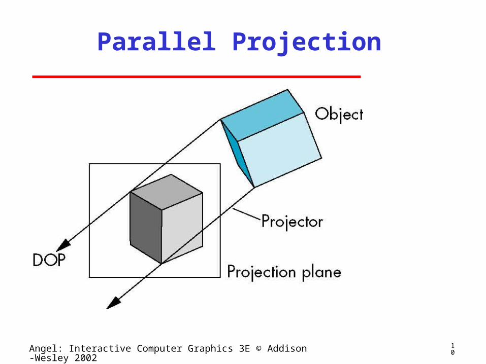
• Standard projections project onto a plane• Projectors are lines that either
converge at a center of projection
are parallel
• Such projections preserve lines but not necessarily angles
• Nonplanar projections are needed for applications such as map construction

6Angel: Interactive Computer Graphics 3E © Addison-Wesley 2002
Classical Projections

7Angel: Interactive Computer Graphics 3E © Addison-Wesley 2002
Perspective vs Parallel
• Computer graphics treats all projections the same and implements them with a single pipeline
• Classical viewing developed different techniques for drawing each type of projection
• Fundamental distinction is between parallel and perspective viewing even though mathematically parallel viewing is the limit of perspective viewing
8Angel: Interactive Computer Graphics 3E © Addison-Wesley 2002
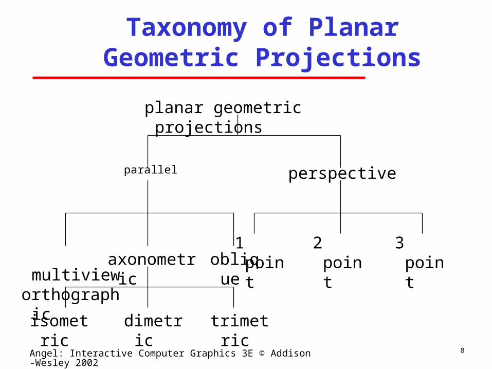
Taxonomy of Planar Geometric Projections
parallel perspective
axonometric multivieworthographic
oblique
isometric dimetric trimetric
2 point1 point 3 point
planar geometric projections
9Angel: Interactive Computer Graphics 3E © Addison-Wesley 2002
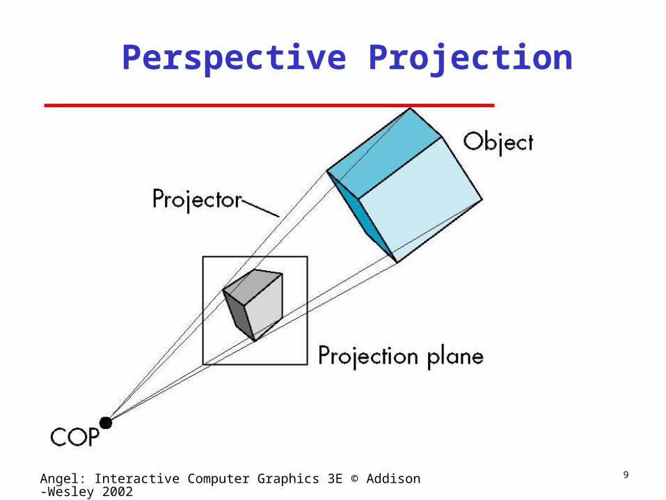
Perspective Projection
10Angel: Interactive Computer Graphics 3E © Addison-Wesley 2002
Parallel Projection
11Angel: Interactive Computer Graphics 3E © Addison-Wesley 2002
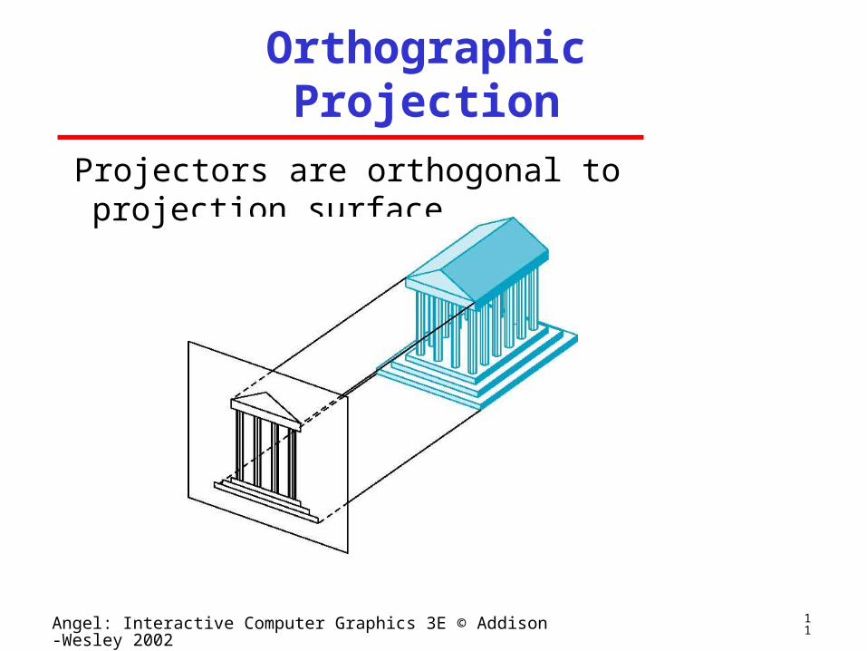
Orthographic Projection
Projectors are orthogonal to projection surface
12Angel: Interactive Computer Graphics 3E © Addison-Wesley 2002
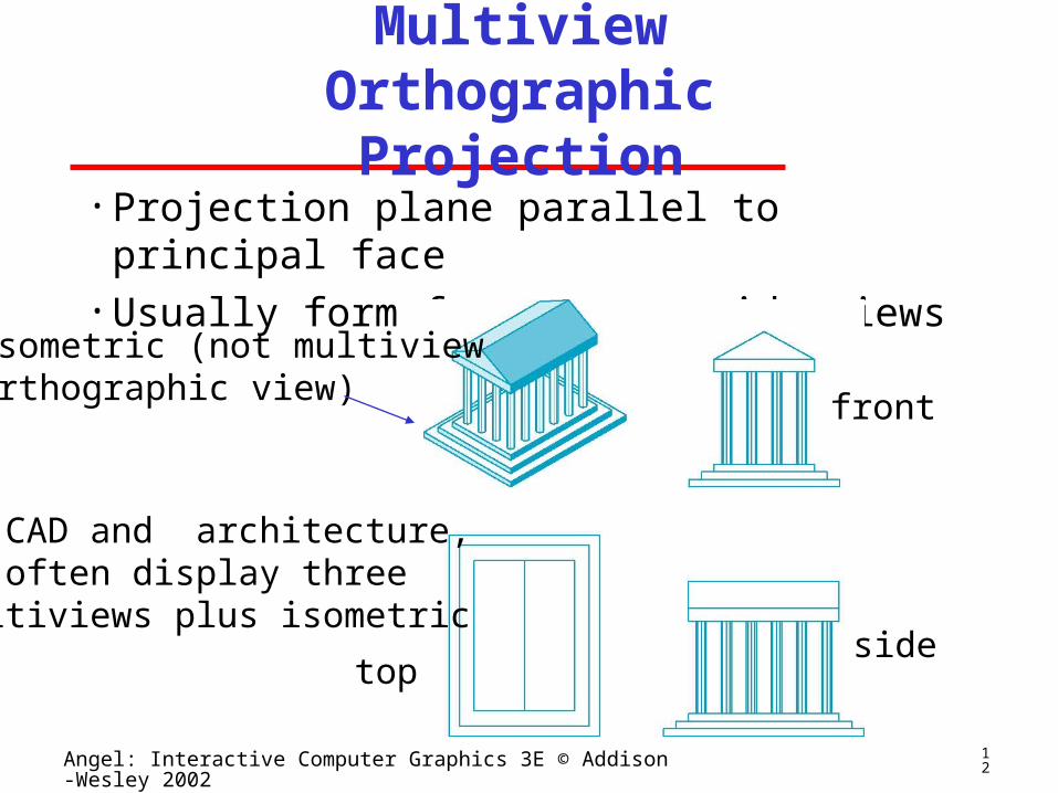
Multiview Orthographic Projection
• Projection plane parallel to principal face• Usually form front, top, side views
isometric (not multivieworthographic view) front
sidetop
in CAD and architecture, we often display three multiviews plus isometric

13Angel: Interactive Computer Graphics 3E © Addison-Wesley 2002
Advantages and Disadvantages
• Preserves both distances and angles Shapes preserved
Can be used for measurements• Building plans• Manuals
• Cannot see what object really looks like because many surfaces hidden from view
Often we add the isometric

14Angel: Interactive Computer Graphics 3E © Addison-Wesley 2002
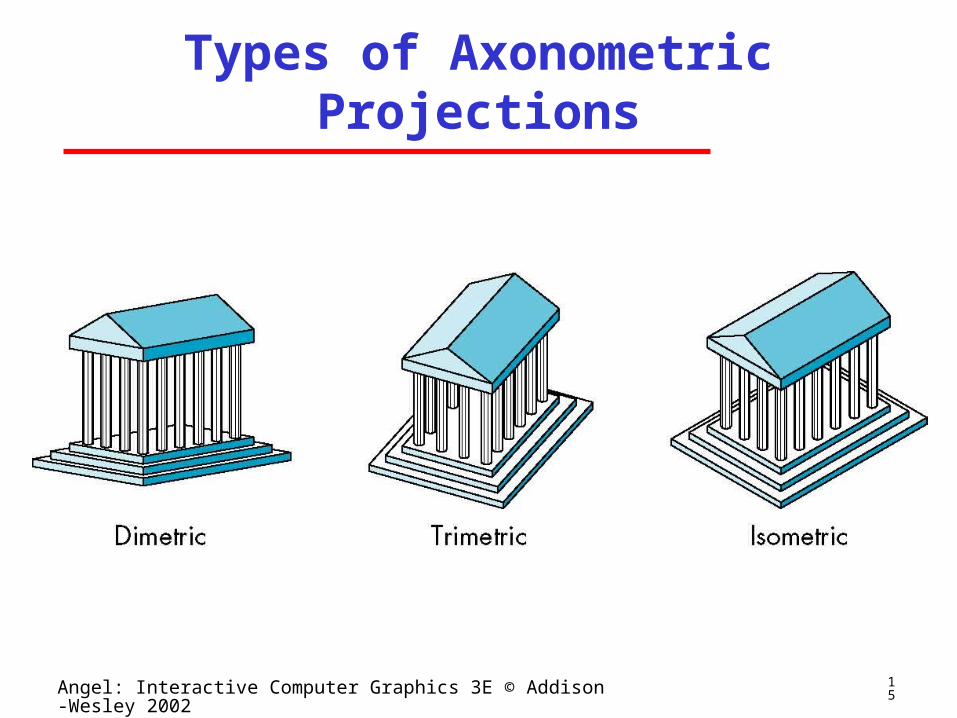
Axonometric Projections
Allow projection plane to move relative to object
classify by how many angles ofa corner of a projected cube are the same
none: trimetrictwo: dimetricthree: isometric
1
32
15Angel: Interactive Computer Graphics 3E © Addison-Wesley 2002
Types of Axonometric Projections
16Angel: Interactive Computer Graphics 3E © Addison-Wesley 2002
Advantages and Disadvantages
• Lines are scaled (foreshortened) but can find scaling factors
• Lines preserved but angles are not Projection of a circle in a plane not parallel to the
projection plane is an ellipse
• Can see three principal faces of a box-like object
• Some optical illusions possible Parallel lines appear to diverge
• Does not look real because far objects are scaled the same as near objects
• Used in CAD applications
17Angel: Interactive Computer Graphics 3E © Addison-Wesley 2002
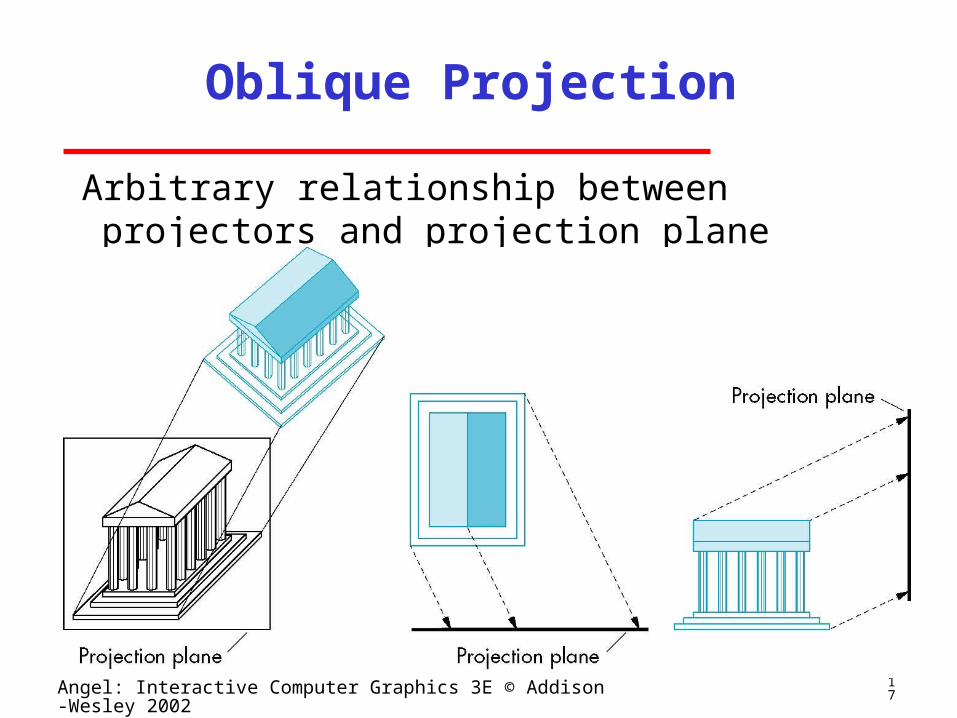
Oblique Projection
Arbitrary relationship between projectors and projection plane

18Angel: Interactive Computer Graphics 3E © Addison-Wesley 2002
Advantages and Disadvantages
• Can pick the angles to emphasize a particular face
Architecture: plan oblique, elevation oblique• Angles in faces parallel to projection plane are preserved while we can still see “around” side
• In physical world, cannot create with simple camera; possible with bellows camera or special lens (architectural)

19Angel: Interactive Computer Graphics 3E © Addison-Wesley 2002
Perspective Projection
Projectors coverge at center of projection

20Angel: Interactive Computer Graphics 3E © Addison-Wesley 2002
Vanishing Points
• Parallel lines (not parallel to the projection plan) on the object converge at a single point in the projection (the vanishing point)
• Drawing simple perspectives by hand uses these vanishing point(s)
vanishing point
21Angel: Interactive Computer Graphics 3E © Addison-Wesley 2002
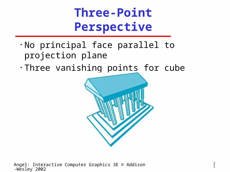
Three-Point Perspective
• No principal face parallel to projection plane• Three vanishing points for cube

22Angel: Interactive Computer Graphics 3E © Addison-Wesley 2002
Two-Point Perspective
• On principal direction parallel to projection plane• Two vanishing points for cube
23Angel: Interactive Computer Graphics 3E © Addison-Wesley 2002
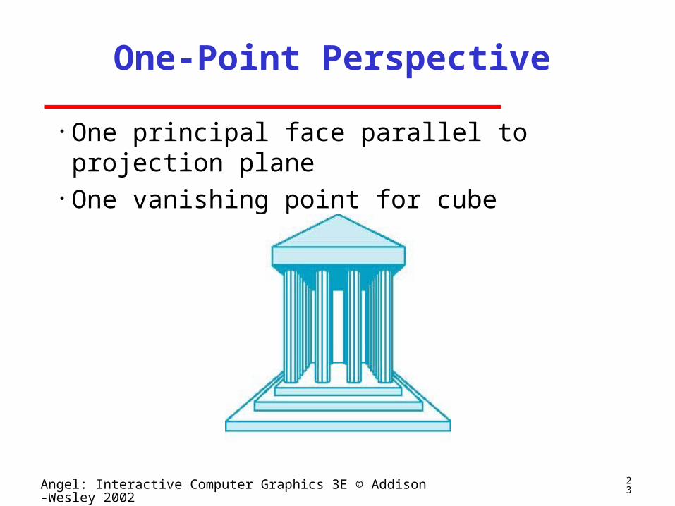
One-Point Perspective
• One principal face parallel to projection plane• One vanishing point for cube
24Angel: Interactive Computer Graphics 3E © Addison-Wesley 2002
Advantages and Disadvantages
• Objects further from viewer are projected smaller than the same sized objects closer to the viewer (diminuition)
Looks realistic• Equal distances along a line are not projected into equal distances (nonuniform foreshortening)
• Angles preserved only in planes parallel to the projection plane
• More difficult to construct by hand than parallel projections (but not more difficult by computer)


