
CSE331 W07&8.1 Irwin Fall 2007 PSU
CSE 331Computer Organization and
DesignFall 2007
Week 7&8
Section 1: Mary Jane Irwin (www.cse.psu.edu/~mji)
Section 2: Krishna Narayanan
Course material on ANGEL: cms.psu.edu
[adapted from D. Patterson slides]

CSE331 W07&8.2 Irwin Fall 2007 PSU
Head’s Up Last week’s material
Intro to VHDL This week’s material
Number representation, basic arithmetic ops, MIPS ALU design
- Reading assignment – PH 3.1-3.5, B.5-B.6 Next week’s material
Designing a MIPS single cycle datapath- Reading assignment – PH 5.1-5.3, B.7
Reminders HW 6 is due Monday, Oct 29th (by 11:55pm) Quiz 5 closes Thursday, Oct 25th (by 11:55pm) Exam #1 take home solution due Thursday, Nov 1st (by
11:55pm) Exam #2 is Thursday, Nov 8, 6:30 to 7:45pm
CSE331 W07&8.3 Irwin Fall 2007 PSU
Architects write the checks that the design engineers have to cash. If the amount is too high, the whole project goes bankrupt.
Design engineers must constantly juggle many conflicting demands: schedule, performance, power dissipation, features, testing, documentation, training and hiring.
The Pentium Chronicles, Colwell, pg. 64 & 63
CSE331 W07&8.4 Irwin Fall 2007 PSU
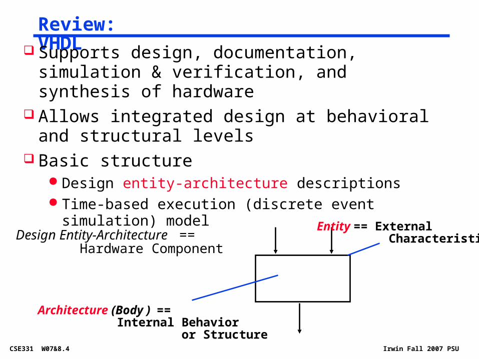
Review: VHDL Supports design, documentation, simulation &
verification, and synthesis of hardware Allows integrated design at behavioral and structural
levels Basic structure
Design entity-architecture descriptions Time-based execution (discrete event simulation) model
Design Entity-Architecture == Hardware Component
Entity == External Characteristics
Architecture (Body ) == Internal Behavior or Structure

CSE331 W07&8.5 Irwin Fall 2007 PSU
Review: Entity-Architecture Features Entity defines externally visible characteristics
Ports: channels of communication - signal names for inputs, outputs, clocks, control
Generic parameters: define class of components- timing characteristics, size (fan-in), fan-out
Architecture defines the internal behavior or structure of the circuit
Declaration of internal signals Description of behavior
- collection of Concurrent Signal Assignment (CSA) statements (indicated by <=); can also model temporal behavior with the delay annotation
- one or more processes containing CSAs and (sequential) variable assignment statements (indicated by :=)
Description of structure- interconnections of components; underlying behavioral
models of each component must be specified

CSE331 W07&8.6 Irwin Fall 2007 PSU
Arithmetic
Where we've been Abstractions
- Instruction Set Architecture (ISA)- Assembly and machine language
What's up ahead Implementing the architecture (in VHDL)
32
32
32
m (operation)
result
A
B
ALU
4
zero ovf
11
CSE331 W07&8.7 Irwin Fall 2007 PSU
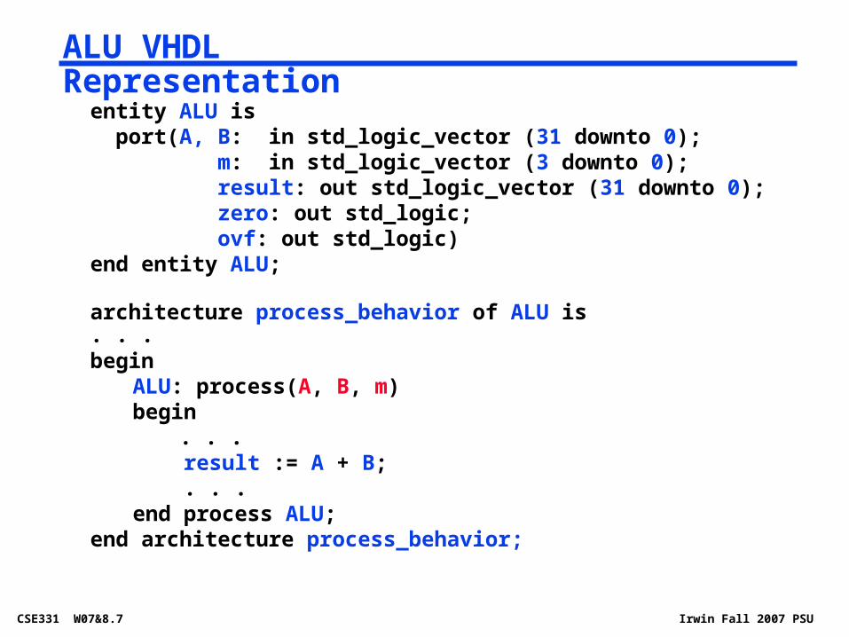
ALU VHDL Representation
entity ALU is port(A, B: in std_logic_vector (31 downto 0);
m: in std_logic_vector (3 downto 0); result: out std_logic_vector (31 downto 0); zero: out std_logic; ovf: out std_logic)
end entity ALU;
architecture process_behavior of ALU is. . .begin
ALU: process(A, B, m)begin
. . . result := A + B; . . .end process ALU;
end architecture process_behavior;

CSE331 W07&8.8 Irwin Fall 2007 PSU
Machine Number Representation Bits are just bits (have no inherent meaning)
conventions define the relationships between bits and numbers
Binary numbers (base 2) - integers0000 0001 0010 0011 0100 0101 . . . in decimal from 0 to 2n-1 for n bits
Of course, it gets more complicated storage locations (e.g., register file words) are finite, so
have to worry about overflow (i.e., when the number is too big to fit into 32 bits)
have to be able to represent negative numbers, e.g., how do we specify -8 in
addi $sp, $sp, -8 #$sp = $sp - 8 in real systems have to provide for more that just
integers, e.g., fractions and real numbers (and floating point) and alphanumeric (characters)

CSE331 W07&8.9 Irwin Fall 2007 PSU
Possible RepresentationsSign Mag. Two’s Comp. One’s Comp.
1000 = -8
1111 = -7 1001= -7 1000 = -7
1110 = -6 1010 = -6 1001 = -6
1101 = -5 1011 = -5 1010 = -5
1100 = -4 1100 = -4 1011 = -4
1011 = -3 1101 = -3 1100 = -3
1010 = -2 1110 = -2 1101 = -2
1001 = -1 1111 = -1 1110 = -1
1000 = -0 1111 = -0
0000 = +0 0000 = 0 0000 = +0
0001 = +1 0001 = +1 0001 = +1
0010 = +2 0010 = +2 0010 = +2
0011 = +3 0011 = +3 0011 = +3
0100 = +4 0100 = +4 0100 = +4
0101 = +5 0101 = +5 0101 = +5
0110 = +6 0110 = +6 0110 = +6
0111 = +7 0111 = +7 0111 = +7
Issues:
balance
number of zeros
ease of operations
Which one is best? Why?

CSE331 W07&8.10 Irwin Fall 2007 PSU
32-bit signed numbers (2’s complement):
0000 0000 0000 0000 0000 0000 0000 0000two = 0ten
0000 0000 0000 0000 0000 0000 0000 0001two = + 1ten
0000 0000 0000 0000 0000 0000 0000 0010two = + 2ten
...
0111 1111 1111 1111 1111 1111 1111 1110two = + 2,147,483,646ten
0111 1111 1111 1111 1111 1111 1111 1111two = + 2,147,483,647ten
1000 0000 0000 0000 0000 0000 0000 0000two = – 2,147,483,648ten
1000 0000 0000 0000 0000 0000 0000 0001two = – 2,147,483,647ten
1000 0000 0000 0000 0000 0000 0000 0010two = – 2,147,483,646ten
...
1111 1111 1111 1111 1111 1111 1111 1101two = – 3ten
1111 1111 1111 1111 1111 1111 1111 1110two = – 2ten
1111 1111 1111 1111 1111 1111 1111 1111two = – 1ten
What if the bit string represented addresses? need operations that also deal with only positive (unsigned)
integers
maxint
minint
MIPS Representations

CSE331 W07&8.11 Irwin Fall 2007 PSU
Negating a two's complement number – complement all the bits and then add a 1 remember: “negate” and “invert” are quite different!
Converting n-bit numbers into numbers with more than n bits: MIPS 16-bit immediate gets converted to 32 bits for
arithmetic sign extend - copy the most significant bit (the sign bit)
into the other bits0010 -> 0000 00101010 -> 1111 1010
sign extension versus zero extend (lb vs. lbu)
Two's Complement Operations

CSE331 W07&8.12 Irwin Fall 2007 PSU
Design the MIPS Arithmetic Logic Unit (ALU) Must support the Arithmetic/Logic
operations of the ISAadd, addi, addiu, addu
sub, subu
mult, multu, div, divu
sqrt
and, andi, nor, or, ori, xor, xori
beq, bne, slt, slti, sltiu, sltu
32
32
32
m (operation)
result
A
B
ALU
4
zero ovf
11
With special handling for sign extend – addi, addiu, slti, sltiu zero extend – andi, ori, xori overflow detection – add, addi, sub
CSE331 W07&8.13 Irwin Fall 2007 PSU
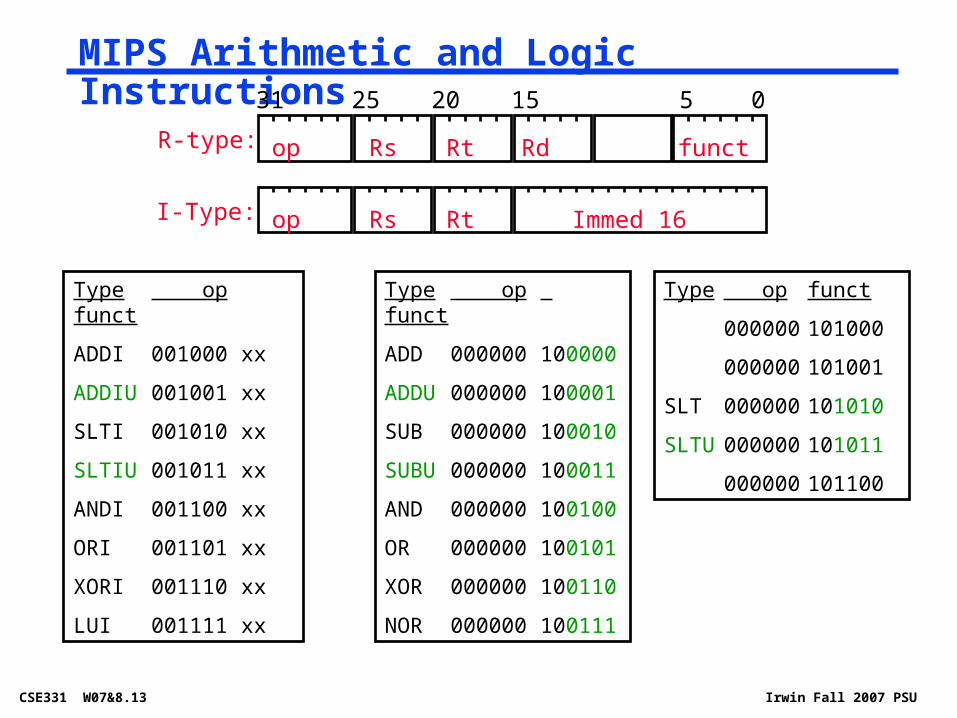
MIPS Arithmetic and Logic Instructions
R-type:
I-Type:
31 25 20 15 5 0
op Rs Rt Rd funct
op Rs Rt Immed 16
Type op funct
ADDI 001000 xx
ADDIU 001001 xx
SLTI 001010 xx
SLTIU 001011 xx
ANDI 001100 xx
ORI 001101 xx
XORI 001110 xx
LUI 001111 xx
Type op funct
ADD 000000 100000
ADDU 000000 100001
SUB 000000 100010
SUBU 000000 100011
AND 000000 100100
OR 000000 100101
XOR 000000 100110
NOR 000000 100111
Type op funct
000000 101000
000000 101001
SLT 000000 101010
SLTU 000000 101011
000000 101100
CSE331 W07&8.14 Irwin Fall 2007 PSU
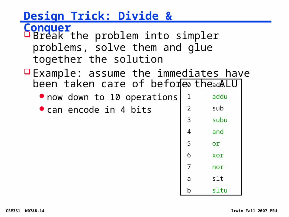
Design Trick: Divide & Conquer
Break the problem into simpler problems, solve them and glue together the solution
Example: assume the immediates have been taken care of before the ALU
now down to 10 operations can encode in 4 bits
0 add
1 addu
2 sub
3 subu
4 and
5 or
6 xor
7 nor
a slt
b sltu

CSE331 W07&8.16 Irwin Fall 2007 PSU
Just like in grade school (carry/borrow 1s) 0111 0111 0110+ 0110 - 0110 - 0101
Two's complement operations are easy do subtraction by negating and then adding
0111 0111 - 0110 + 1010
Overflow (result too large for finite computer word) e.g., adding two n-bit numbers does not yield an n-bit number
0111+ 0001
Addition & Subtraction
1101 0001 0001
0001 1 0001
1000

CSE331 W07&8.17 Irwin Fall 2007 PSU
Building a 1-bit Binary Adder
1 bit Full Adder
A
BS
carry_in
carry_out
S = A xor B xor carry_in carry_out = A&B | A&carry_in | B&carry_in (majority function)
How can we use it to build a 32-bit adder?
How can we modify it easily to build an adder/subtractor?
A B carry_in carry_out S
0 0 0 0 0
0 0 1 0 1
0 1 0 0 1
0 1 1 1 0
1 0 0 0 1
1 0 1 1 0
1 1 0 1 0
1 1 1 1 1

CSE331 W07&8.18 Irwin Fall 2007 PSU
Building 32-bit Adder
1-bit FA
A0
B0
S0
c0=carry_in
c1
1-bit FA
A1
B1
S1
c2
1-bit FA
A2
B2
S2
c3
c32=carry_out
1-bit FA
A31
B31
S31
c31
. .
.
Just connect the carry-out of the least significant bit FA to the carry-in of the next least significant bit and connect . . .
Ripple Carry Adder (RCA)
advantage: simple logic, so small (low cost)
disadvantage: slow and lots of glitching (so lots of energy consumption)

CSE331 W07&8.20 Irwin Fall 2007 PSU
A 32-bit Ripple Carry Adder/Subtractor
Remember 2’s complement is just
complement all the bits
add a 1 in the least significant bit
A 0111 0111 B - 0110 +
1-bit FA S0
c0=carry_in
c1
1-bit FA S1
c2
1-bit FA S2
c3
c32=carry_out
1-bit FA S31
c31
. .
.
A0
A1
A2
A31
B0
B1
B2
B31
add/sub
B0
control(0=add,1=sub) B0 if control = 0
!B0 if control = 1
0001
1001 1
1 0001

CSE331 W07&8.21 Irwin Fall 2007 PSU
Overflow Detection and Effects
Overflow: the result is too large to represent in the number of bits allocated
When adding operands with different signs, overflow cannot occur! Overflow occurs when
adding two positives yields a negative or, adding two negatives gives a positive or, subtract a negative from a positive gives a negative or, subtract a positive from a negative gives a positive
On overflow, an exception (interrupt) occurs Control jumps to predefined address for exception Interrupted address (address of instruction causing the
overflow) is saved for possible resumption
Don't always want to detect (interrupt on) overflow

CSE331 W07&8.22 Irwin Fall 2007 PSU
New MIPS Instructions
Category Instr Op Code Example Meaning
Arithmetic
(R & I format)
add unsigned 0 and 21 addu $s1, $s2, $s3 $s1 = $s2 + $s3
sub unsigned 0 and 23 subu $s1, $s2, $s3 $s1 = $s2 - $s3
add imm.unsigned
9 addiu $s1, $s2, 6 $s1 = $s2 + 6
Data Transfer
ld byte unsigned
24 lbu $s1, 25($s2) $s1 = Mem($s2+25)
ld half unsigned 25 lhu $s1, 25($s2) $s1 = Mem($s2+25)
Cond. Branch (I & R format)
set on less than unsigned
0 and 2b sltu $s1, $s2, $s3 if ($s2<$s3) $s1=1 else $s1=0
set on less than imm unsigned
b sltiu $s1, $s2, 6 if ($s2<6) $s1=1
else $s1=0
Sign extend – addiu, addiu, slti, sltiu Zero extend – andi, ori, xori Overflow detected – add, addi, sub

CSE331 W07&8.24 Irwin Fall 2007 PSU
Those who are not engineers know two certainties: death and taxes. Engineers know a third: there are no perfect designs. … The FDIV flaw was a subtle, complex bug that survived both design and validation.
The Pentium Chronicles, Colwell

CSE331 W07&8.25 Irwin Fall 2007 PSU
Review: MIPS Arithmetic Instructions
R-type:
I-Type:
31 25 20 15 5 0
op Rs Rt Rd funct
op Rs Rt Immed 16
Type op funct
ADD 00 100000
ADDU 00 100001
SUB 00 100010
SUBU 00 100011
AND 00 100100
OR 00 100101
XOR 00 100110
NOR 00 100111
Type op funct
00 101000
00 101001
SLT 00 101010
SLTU 00 101011
00 101100
0 add
1 addu
2 sub
3 subu
4 and
5 or
6 xor
7 nor
a slt
b sltu
expand immediates to 32 bits before ALU10 operations so can encode in 4 bits
32
32
32
m (operation)
result
A
B
ALU
4
zeroovf
11

CSE331 W07&8.26 Irwin Fall 2007 PSU
Review: A 32-bit Adder/Subtractor
1-bit FA S0
c0=carry_in
c1
1-bit FA S1
c2
1-bit FA S2
c3
c32=carry_out
1-bit FA S31
c31
. .
.
Built out of 32 full adders (FAs) A0
B0
A1
B1
A2
B2
A31
B31
add/subt
1 bit FA
A
BS
carry_in
carry_out
S = A xor B xor carry_in
carry_out = A&B | A&carry_in | B&carry_in (majority function)
Small but slow!

CSE331 W07&8.27 Irwin Fall 2007 PSU
Minimal Implementation of a Full Adder
architecture concurrent_behavior of full_adder is
signal t1, t2, t3, t4, t5: std_logic;
begin
t1 <= not A after 1 ns;
t2 <= not cin after 1 ns;
t4 <= not((A or cin) and B) after 2 ns;
t3 <= not((t1 or t2) and (A or cin)) after 2 ns;
t5 <= t3 nand B after 2 ns;
S <= not((B or t3) and t5) after 2 ns;
cout <= not(t1 or t2) and t4) after 2 ns;
end architecture concurrent_behavior;
Can you create the equivalent schematic? Can you determine worst case delay (the worst case timing path through the circuit)?
Gate library: inverters, 2-input nands, or-and-inverters

CSE331 W07&8.28 Irwin Fall 2007 PSU
Also need to support the logic operations (and, nor, or, xor) Bit wise operations (no carry operation involved) Need a logic gate for each function and a mux to choose
the output Also need to support the set-on-less-than
instruction (slt) Uses subtraction to determine if (a – b) < 0 (implies a < b)
Also need to support test for equality (bne, beq) Again use subtraction: (a - b) = 0 implies a = b
Also need to add overflow detection hardware overflow detection enabled only for add, addi, sub
Immediates are sign extended outside the ALU with wiring (i.e., no logic needed)
Tailoring the ALU to the MIPS ISA

CSE331 W07&8.29 Irwin Fall 2007 PSU
A Simple ALU Cell with Logic Op Support
1-bit FA
carry_in
carry_out
A
B
add/subt
add/subt
result
op

CSE331 W07&8.32 Irwin Fall 2007 PSU
Modifying the ALU Cell for slt
1-bit FA
A
B
result
carry_in
carry_out
add/subt op
add/subt
less
0
1
2
3
6
7

CSE331 W07&8.34 Irwin Fall 2007 PSU
Modifying the ALU for slt
0
0set
First perform a subtraction
Make the result 1 if the subtraction yields a negative result
Make the result 0 if the subtraction yields a positive result
tie the most significant sum bit (sign bit) to the low order less input
A1
B1
A0
B0
A31
B31
+
result1
less
+
result0
less
+
result31
less
. . .

CSE331 W07&8.36 Irwin Fall 2007 PSU
Modifying the ALU for Zero
+
A1
B1
result1
less
+
A0
B0
result0
less
+
A31
B31
result31
less
. . .
0
0
set
First perform subtraction
Insert additional logic to detect when all result bits are zero
zero
. . .
add/subtop
Note zero is a 1 when result is all zeros

CSE331 W07&8.38 Irwin Fall 2007 PSU
Overflow Detection Overflow occurs when the result is too large to
represent in the number of bits allocated adding two positives yields a negative or, adding two negatives gives a positive or, subtract a negative from a positive gives a negative or, subtract a positive from a negative gives a positive
On your own: Prove you can detect overflow by: Carry into MSB xor Carry out of MSB
1
1
1 10
1
0
1
1
0
0 1 1 1
0 0 1 1+
7
3
0
1
– 6
1 1 0 0
1 0 1 1+
–4
– 5
71
0
CSE331 W07&8.39 Irwin Fall 2007 PSU
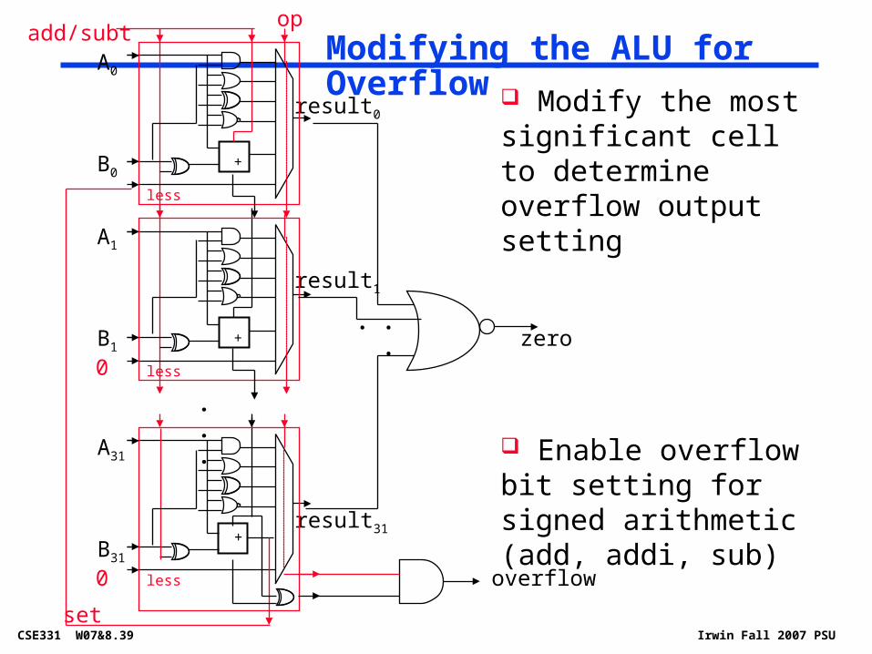
Modifying the ALU for Overflow
+
A1
B1
result1
less
+
A0
B0
result0
less
+
A31
B31
result31
less
. . .
0
0
set
Modify the most significant cell to determine overflow output setting
Enable overflow bit setting for signed arithmetic (add, addi, sub)
zero
. . .
add/subtop
overflow

CSE331 W07&8.40 Irwin Fall 2007 PSU
But What about Performance? Critical path of n-bit ripple-carry adder is n*CP
Design trick – throw hardware at it (Carry Lookahead)
A0
B0
1-bitALU
Result0
CarryIn0
CarryOut0
A1
B1
1-bitALU
Result1
CarryIn1
CarryOut1
A2
B2
1-bitALU
Result2
CarryIn2
CarryOut2
A3
B3
1-bitALU
Result3
CarryIn3
CarryOut3

CSE331 W07&8.41 Irwin Fall 2007 PSU
More complicated than addition Can be accomplished via shifting and adding
0010 (multiplicand) x_1011 (multiplier)
0010 0010 (partial product
0000 array) 0010 00010110 (product)
Double precision product produced More time and more area to compute
Multiplication

CSE331 W07&8.42 Irwin Fall 2007 PSU
Multiply produces a double precision product
mult $s0, $s1 # hi||lo = $s0 * $s1
Low-order word of the product is left in processor register lo and the high-order word is left in register hi
Instructions mfhi rd and mflo rd are provided to move the product to (user accessible) registers in the register file
MIPS Multiply Instruction
op rs rt rd shamt funct
Multiplies are done by fast, dedicated hardware and are much more complex (and slower) than adders
Hardware dividers are even more complex and even slower; ditto for hardware square root

CSE331 W07&8.43 Irwin Fall 2007 PSU
Division Division is just a bunch of quotient digit guesses
and left shifts and subtracts
dividenddivisor
partialremainderarray
quotientn
n
remainder
n
0 0 0
0
0
0
CSE331 W07&8.44 Irwin Fall 2007 PSU
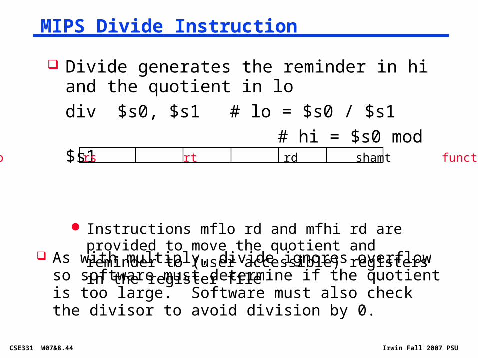
Divide generates the reminder in hi and the quotient in lo
div $s0, $s1 # lo = $s0 / $s1
# hi = $s0 mod $s1
Instructions mflo rd and mfhi rd are provided to move the quotient and reminder to (user accessible) registers in the register file
MIPS Divide Instruction
As with multiply, divide ignores overflow so software must determine if the quotient is too large. Software must also check the divisor to avoid division by 0.
op rs rt rd shamt funct
CSE331 W07&8.45 Irwin Fall 2007 PSU
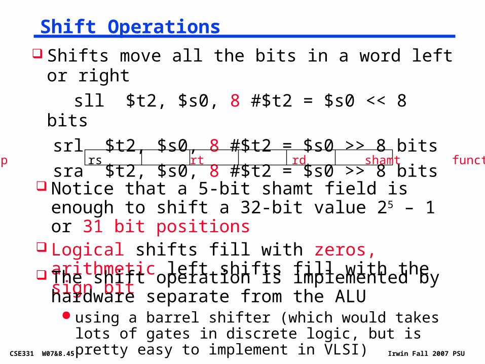
Shift Operations Shifts move all the bits in a word left or right
sll $t2, $s0, 8 #$t2 = $s0 << 8 bits
srl $t2, $s0, 8 #$t2 = $s0 >> 8 bits
sra $t2, $s0, 8 #$t2 = $s0 >> 8 bits
op rs rt rd shamt funct
Notice that a 5-bit shamt field is enough to shift a 32-bit value 25 – 1 or 31 bit positions
Logical shifts fill with zeros, arithmetic left shifts fill with the sign bit
The shift operation is implemented by hardware separate from the ALU
using a barrel shifter (which would takes lots of gates in discrete logic, but is pretty easy to implement in VLSI)

CSE331 W07&8.46 Irwin Fall 2007 PSU
Parallel Programmable ShiftersD
ata
In
Control
Dat
a O
ut
Shift amount (Sh4Sh3Sh2Sh1Sh0)Shift direction (left, right)Shift type (logical, arithmetic)
=

CSE331 W07&8.48 Irwin Fall 2007 PSU
Logarithmic Shifter StructureD
ata
In
Dat
a O
utshifts of 0 or 1 bits
!Sh0Sh0
0,1shifts
shifts of 0 or 2 bits
!Sh1Sh1
0,1,2,3shifts
shifts of 0 or 4 bits
!Sh2Sh2
0,1,2,3,4,5,6,7 shifts
shifts of 0 or 8 bits
!Sh3Sh3
0,1,2…15 shifts
shifts of 0
or 16 bits
!Sh4Sh4
0,1,2…31 shifts
Sh0 & right
datainidataouti
dataini-1
dataini+1
Sh0 & left
!Sh0
Sh1 & right
datainidataouti
dataini-2
dataini+2
Sh1 & left
!Sh1
CSE331 W07&8.49 Irwin Fall 2007 PSU
Wrap-Up
We can build an ALU to support the MIPS ISA we can efficiently perform subtraction using two’s
complement we can replicate a 1-bit ALU to produce a 32-bit ALU
Important points about hardware all of the gates are always working (concurrently) the speed of a gate is affected by the number of inputs
to the gate (fan-in) and the number of gates that the output is connected to (fan-out)
the speed of a circuit is affected by the speed of and number of gates in series (on the “critical path” or the “number of levels of logic”) and the length of wires interconnecting the gates
Our primary focus is comprehension, however clever changes to organization can improve
performance (similar to using better algorithms in software)


