Title: Site | Structure | Architecture – Projects that Create Change
Authors: Leo Chow, Skidmore, Owings & Merrill LLPMark Sarkisian, Skidmore, Owings & Merrill LLP
Subjects: Architectural/DesignStructural EngineeringUrban Design
Keywords: SeismicStructural EngineeringUrban Design
Publication Date: 2017
Original Publication: International Journal of High-Rise Buildings Volume 6 Number 3
Paper Type: 1. Book chapter/Part chapter2. Journal paper3. Conference proceeding4. Unpublished conference paper5. Magazine article6. Unpublished
© Council on Tall Buildings and Urban Habitat / Leo Chow; Mark Sarkisian
ctbuh.org/papers

International Journal of High-Rise Buildings
September 2017, Vol 6, No 3, 237-248
https://doi.org/10.21022/IJHRB.2017.6.3.237
International Journal of
High-Rise Buildingswww.ctbuh-korea.org/ijhrb/index.php
Site | Structure | Architecture - Projects that Create Change
Leo Chow†, AIA, Mark P. Sarkisian†, and PE SE LEED
Skidmore, Owings & Merrill LLP, One Front Street, Suite 2400, San Francisco, CA 94111, USA
Abstract
China’s rapid growth has created great opportunities for design and construction of projects that not only transform sites butcities. This work combines local, national, and international expertise in developing memorable designs that seek to humanizeurban life and emphasize the importance of visionary clients. Innovative examples of work in China will be presented withemphasis on three iconic projects designed and built for Poly Corporation based in China. These projects include developmentsin Beijing and Guangzhou and introduce the use of locally supplied materials and construction techniques. The Poly CorporateHeadquarters, the Poly Real Estate Headquarters, and the Poly International Plaza, and will be described through innovativeideas that integrate urban planning, structure, and architecture.
Keywords: Structural steel, Efficiency, Cable net, Mechanism, Seismic
1. Introduction
The rapid and sustained growth of the Chinese econ-
omy, the desire of some enlightened clients to create sig-
nature buildings, and the ability of Chinese domestic fab-
ricators to produce quality architectural components have
all coalesced into an unprecedented period of design opp-
ortunity. In particular, the Poly Corporation has been a
champion of supporting high quality design that has not
only transformed local development but has influence
ideas for other building projects around the world.
The Poly Corporate Headquarters building in Beijing,
China was the first to be designed and built. Creating a
“window to the world” this unusual mixed-use develop-
ment includes 24 stories of office space, an eight-story
hanging museum ‘lantern’ structure and a 90 meter-tall
atrium enclosed by the world’s largest cable-net supported
glass wall. The second was the Poly Real Estate Head-
quarters located in Guangzhou, China. Located on the
bank of the Pearl River, this project consists of two
slender towers carefully integrated with a ground level
landscaped area as well as a podium. This project prov-
ides column-free office space, a structure that has a dual
purpose of shading the southern facades, and a vertical
transportation system that uses translucent and transparent
glass. Located approximately half way between the For-
bidden City and the Beijing Capital Airport, the third pro-
ject, Poly International Plaza occupies a prominent posi-
tion immediately adjacent to the Capital Airport Express-
way and the interchange with the Fifth Ring Road. The
building offers a unique light-filled spatial experience for
entering and moving through the office building, utilizes
a long-span structure to open up interior spaces, and emp-
loys a highly sustainable architectural/mechanical engin-
eering approach to address climate and air quality issues
particular to Beijing.
2. The Rocker Mechanism and the Tallest Cable Net in the World - Poly Corporate Headquarters
2.1. Architectural Concept
The client’s goal for this headquarters building was to
represent the company’s disparate subsidiaries as a unified
whole. The program for the building contains a wide range
of spaces including office, retail, restaurants and the Poly
Museum. The museum, established by one of the comp-
any’s subsidiaries, has the unique purpose of repatriating
China’s cultural antiquities through purchases at interna-
tional auctions.
The project is prominently located at a major intersec-
tion along Beijing’s second ring road, northeast of the
Forbidden City. The site’s primary orientation is northeast
toward the intersection and beyond to the client’s existing
headquarters building. The triangular form minimizes the
perimeter length exposed to the elements, while a series
of interior atriums provide additional interior surface area
to give office areas maximum access to daylight. The
result is a simple ‘L’ shaped office plan that cradles a large
atrium (Fig. 1). The exterior walls of the atrium are com-
prised of minimal glass membranes supported on two-
way cable nets to maximize visual and solar transparency.
†Corresponding authors: Leo ChowTel: +1-1-415-352-6824; Fax: +1-1-415-398-3214E-mail: [email protected] authors: Mark SarkisianTel: +1-1-415-352-6803; Fax: +1-1-415-398-3214E-mail: [email protected]

238 Leo Chow et al. | International Journal of High-Rise Buildings
Forming a unique solution to the unusual mixed-use
requirements of this project, the Poly Museum is sus-
pended within a ‘Lantern’ in the main atrium space (Fig.
2). This defined programmatic volume within the atrium
space, is both isolated from and yet enclosed by the main
building volume. Its crystalline surface of laminated pat-
terned glass is pleated to increase its light reflecting/ref-
racting qualities. Inside the ‘Lantern,’ exhibit and lease
spaces are enclosed by wood walls which control daylight
while common circulation areas occupy the void between
the solids and the glazed perimeter walls.
Secondary ‘Sunset’ and ‘All-Day’ atriums cut through
the west (Fig. 3) and south (Fig. 4) legs of the ‘L’ to act
as daylight chambers for bringing direct sunlight into the
main atrium. The exterior walls of these atriums are com-
prised of minimal glass membranes supported by two way
cable nets in order to maximize visual and solar trans-
parency. The main atrium’s cable-net is stiffened by two
‘V’-cables that are in turn counterweighted and kept in
tension by the self-weight of the suspended ‘Museum Lan-
tern’ (Fig. 5).
The cable-net wall is 90 meters high by 60 meters wide
- dimensions making a simple cable-net supported wall
uneconomical. The design is achieved by folding the
cable-net around diagonal V-shaped, parallel-strand
bridge cables, subdividing the wall into three facets and
reducing the effective cable spans. The parallel-strand
cables also support the ‘lantern’ as it hangs in the atrium
space without any columns extending to grade. Gravity
loads from the ‘lantern’ are used to induce high levels of
pre-tension in the parallel-strand cables. An innovative
‘rocker mechanism’ is used to isolate the cable hanger
system from forces induced by lateral drift. The ‘rocker
mechanism’ is architecturally ‘celebrated’ - an exposed
articulated joint mechanism made of rigid pin-connected
castings which perform as a pulley equivalent.
The project is prominently located at a major intersec-
tion along Beijing’s second ring road, northeast of the
Forbidden City. The site’s primary orientation is northeast
toward the intersection and beyond to the client’s existing
headquarters building. The triangular form minimizes the
Figure 1. Atrium Concepts.
Figure 2. The ‘Museum Lantern’.
Figure 3. Typical High-Rise Plan.
Figure 4. Typical Low-Rise Plan.

Site | Structure | Architecture - Projects that Create Change 239
perimeter exposed to the elements, whilst a series of inte-
rior atria provide additional interior surface area to give
office areas maximum access to daylight. The result is a
simple ‘L’ shaped office plan that cradles a large atrium.
The exterior walls of the atrium are comprised of minimal
glass membranes supported on two-way cable nets to
maximize visual and solar transparency (Figs. 6 and 7).
2.2. Technology
While conceptually simple, cable-net curtain wall sys-
tems may still be considered an exotic solution for the
structural support of glass curtain walls. However, the
completion of several major walls around the world has
established a proven track record of an achievable scale
and level of transparency. Planar two-way cable systems
support and stabilize glass facades through the resistance
to deformation of the two-way pre-stressed net. Gravita-
tional loads from the glass elements are carried through
the attachment nodes to the vertical cables, and up to a
transfer structure in the base building above. Lateral def-
ormations due to wind and seismic loadings are resisted
by the tendency of each of the horizontal and vertical
cables to return to its straight-line configuration between
supports, while being subject to a perpendicular force.
The flexible nature of a planar cable-net under lateral
loading means that the critical design goal is limiting
deflection through adjusting axial stiffness of the cables,
and the cable pre-stress. Deflection limits of L/40 to L/50
are generally set for the design loading condition (typic-
ally the 50-year wind event), to protect the integrity of the
glass and sealants and to minimize a perception of weak-
ness by the building’s occupants.
2.3. Challenge
The Poly Corporate Headquarters project is a 100 m tall
composite structure and includes a 90 m tall atrium enc-
losed by a cable-net glass wall, 90 m high by 60 m wide.
The scale of this wall greatly exceeds that which has been
built before, introducing specific challenges that are not
critical in smaller walls. SOM’s preliminary analysis sho-
Figure 5. Northeast Elevation Rendering.
Figure 6. Northeast Building Elevation.
Figure 7. Upward View from Atrium Floor.

240 Leo Chow et al. | International Journal of High-Rise Buildings
wed that the cable-net spans were too large to be econo-
mically achieved using a simple two-way cable-net design.
SOM determined however that the cable-net could be
achieved by subdividing the large cable-net area into
three smaller zones by folding the cable-net into a faceted
surface, and introducing a relatively stiff element along the
fold lines. The faceted cable-net solution allows the indi-
vidual sections of the cable-net to span to a virtual bound-
ary condition at the fold line, effectively shortening the
spans. Rather than introduce a beam or truss element to
stiffen the fold line, a large diameter cable under signifi-
cant pre-stress is used. The largest of these primary cables
is 275 mm in diameter and consists of a parallel strand
cable bundle of 199 individual 1×7 strands, each strand
being 15.2 mm in diameter. The largest cable is pre-stre-
ssed to 17,000 kN, and experiences a maximum in service
loading of 18,300 kN during a 100 year wind event. Using
the faceted design solution, the typical horizontal and
vertical cables are limited in diameter to 34 mm and 26
mm respectively.
By introducing the large diameter diagonal cables, an
issue is created as one is solved. As the base building
structure is subject to seismic and wind loads, it experi-
ences inter-story drifts as any building structure does. By
connecting a point on one floor slab with an axially stiff
element diagonally to another point 45 m higher up the
structure, the diagonal cable element behaves as a brace
element and tries to resist the base building drift. Thus
analyzed, the forces in the main cables were too great to
be resisted by the main cables, or the base building struc-
ture. However, when the base building drifts in a direc-
tion that causes one diagonal cable to go into tension
(tries to lengthen) the other cable that forms part of the
“V” configuration goes in compression (tries to shorten).
A pulley analogy was developed that allowed the “V”
cables to be considered as a single element, with rotation
at the base of the “V” allowing the length increase of one
cable to be offset against the length decrease of the other
cable (Fig. 8). This allows the base building to drift with-
out significantly increasing or decreasing the level of pre-
stress in the main cables. The pulley analogy was realized
in a buildable form as a cast ‘Rocker Mechanism’. By
crossing the cables and connecting to the rocker casting
arms, the need to provide curved pulley surfaces and cur-
ved sections of the main cable were eliminated (Figs. 9
and 10).
2.4. Performance
The critical service level load condition, (the 50 -year
wind event) was determined through careful Wind Engin-
Figure 8. Pully Equivalent Concept.
Figure 9. The ‘Rocker Mechanism’ Model.
Figure 10. The ‘Rocker’ Installed.

Site | Structure | Architecture - Projects that Create Change 241
eering studies performed by Beijing University. The wind
studies included a traditional rigid model of the building
massing as well as that of the surrounding building fabric,
and an aero-elastic wind tunnel study performed on a
flexible model of the actual cable-net configuration, using
wires and a membrane to replicate the anticipated dyna-
mic response of the cable-net system. This study, likely
the first of its kind to be performed on a cable-net curtain
wall system was used to verify and modify where appro-
priate the results of the rigid model. Analysis and testing
shows that the New Beijing Poly cable-net wall behaves
very much as conceived. The results from the static non-
linear (large displacement) analysis clearly show that the
strategy of subdividing the wall into facets with shorter
individual spans was successful (Fig. 11). This strategy
allows the overall displacements to meet the established
for the project, while maintaining the economic viability
of the project (Fig. 12).
Table 1 illustrates the key attibutes of the northeast cable
net.
3. Braced Concrete Butresses-Poly Real Estate Headquarters
In considering a structure’s life and its effects on the
environment, structural solutions, building orientation and
integrated systems are important considerations. To achi-
eve a high level of sustainability, the structure must allow
the entry natural light and natural ventilation, air distribu-
tion from below the floor, shaded outdoor spaces, green
roofs and minimal material use. The structural concept
for the 525 ft (160 m) twin Poly International Plaza Tow-
ers (Fig. 13) incorporates a long-span concrete floor fra-
ming system with a series of concrete buttress walls to not
only resist gravity and lateral loads but provide shading
of the south facades (Fig. 14) significantly reducing the
need for mechanical cooling of towers over their opera-
tional life.
To further enhance the shading effects, two lines of bra-
ces were incorporated into the south facades of the towers
to provide significant stiffness in the east-west direction
of the towers (long direction), but more importantly, act
to anchor the structure in the north-south (short direction)
of the towers functioning in tandem with the buttress walls
as a “stressed skin” through the action of the outriggers.
The stressed skin acts as a flange to resist compressive
and tensile loads applied in the short direction. See Fig.
15 for the construction of the south façade. See Figs. 16
and 17 for architectural and structural floor plans respec-
tively.
Figure 11. Deflected Shape Under Wind Loading. Figure 12. Completed 90mx60m Folded Cable-Net.
Table 1. Project Summary Statistics
Overall Parameters Main Cables Horizontal Cables Vertical Cables
Height Width Deflect. Dia. Pre-stress Dia. Pre-stress Dia. Pre-stress
90m 60m 928mm 248mm 17MN 36mm 210kN 26mm 90kN

242 Leo Chow et al. | International Journal of High-Rise Buildings
Sustained gravity loads are used as ballast within the
primary lateral load resisting elements achieved through
long-span reinforced concrete framing where compres-
sive loads are placed on both the north and south facade
structural systems. Openings were introduced into the
mid-height of the two towers to provide an area of refuge
during an emergency and to provide an aperture for pre-
dominant winds to pass through the structure. The screen
enclosures at the top of the towers consist of tilted indi-
vidual panels, providing open paths for wind to pass thr-
ough, reducing wind loads on the top of the towers where
they would induce the highest demand on the structure.
Through balancing load on the structure by using an
efficient bracing system on the south facades and the
openings that allowed for winds to pass through the
structure, a 15% savings of structural materials was achi-
eved when compared to conventional structures of the
same height (even with slender forms). See Fig. 18 for an
exploded view of major building components. See Fig. 19
for the completed building.
4. Combining a Concrete Shear Wall with a Diagrid Frame - Poly International Plaza
The Poly International Plaza Tower (Fig. 20), located at
a prominent site approximately half way between the For-
bidden City and Beijing Capital Airport, China, incorpor-
ates a faceted exoskeleton system to create an iconic exte-
rior envelope highly visible in the surrounding skyline ser-
ves as part of the gravity and lateral force resisting system
while allowing for long 18 m (60 ft) column-free spans
combined with the reinforced concrete central core. A
primary design goal of the 32-story office building is to
provide a unique, high-quality work environment utilizing
long span structural framing to open up interior spaces and
achieve a light-filled spatial experience throughout the
tower.
The diagrid perimeter structure is designed to resist
gravity and lateral loads axially, with only minor bending
effects due to the rigid welded nodal connections. The
concrete filled steel tube (CFT) diagrid members serve as
effective axial members to resist high compression loads
due to gravity and lateral overturning, varying from 1300
mm (51”) in diameter at the base to 800 mm (32”) at the
top. The load path of the axial force travels around the
perimeter diagrid down to the base, allowing for long
spans between nodes while providing global stiffness to
distribute lateral forces.
While the helical load path is advantageous in allowing
Figure 13. Poly International Plaza, Guangzhou, China.
Figure 14. Shading Effects on South Façade.
Figure 15. Poly International Plaza Under ConstructionIllustrated Structural Steel Interconnected with ConcreteElements.
Site | Structure | Architecture - Projects that Create Change 243
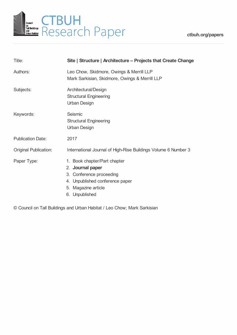
for long perimeter spans and large atriums, the axial forces
in the elliptical exterior diagrid result in tensile perimeter
Figure 16. Typical Architectural Floor Plan.
Figure 17. Typical Structural Floor Plan.
Figure 18. Exploded View Showing Major Building Com-ponents.
Figure 19. South Façade and Base of Tower.

244 Leo Chow et al. | International Journal of High-Rise Buildings
hoop and radial floor diaphragm forces that needed to be
resolved through the perimeter steel framing members at
nodal levels and radial steel floor framing members that
connect the diagrid nodes to the inner concrete core. The
interior reinforced concrete shear walls form an elongated
core that follows the same elliptical shape as the exterior
façade. The shear walls vary in thickness from 1300 mm
(51”) thick in the basement to 400 mm (16”) at the top.
The varying shear wall thickness and diagrid member
diameters were optimized to meet design drift limits
using strain energy optimization with ETABS and Excel
VBA. The combination of the perimeter diagrid and inner
concrete shear wall core create a tube-in-tube lateral force
resisting system, sharing a balanced portion of lateral
forces between the two systems.
An advantage of designing a diagrid structure is the
availability of helical axial load paths for resisting gravity
and lateral loads (Fig. 21) while allowing for a column-
free interior and long span framing without compromis-
ing effective global stiffness.
In a structure with a conventional perimeter moment
frame system, a continuous floor slab diaphragm is needed
to transmit lateral forces to the frames at each level. The
loads then travel down each respective plane of frames to
the building base. In a diagrid system, however, lateral
loads are transmitted to the base in a helical manner not
relying on a continuous diaphragm slab at the building
ends (Fig. 22). The exoskeletal diagrid system on the peri-
meter acts in tandem with the concrete walls at the build-
ing’s core to provide a dual gravity and lateral load resist-
Figure 20. Poly International Plaza Tower Rendering (left), Building Under Construction (right).
Figure 21. Helical Axial Load Path (left).Figure 22. Diagrid System Lateral Load Path vs. Conventional System Lateral Load Path (left to right).

Site | Structure | Architecture - Projects that Create Change 245
ing system with multiple continuous and redundant load
paths.
Since the diagrid members are most efficient as axial
members, connections of the floor diaphragms are limited
to nodal floors to avoid imposing bending demands at the
mid-spans of members. With a four-story tall diagrid mo-
dule, every alternate floor connects to diagrid nodes and
every other intermediate floor requires hangers to connect
to members of the nodal floor above (Fig. 23). These han-
gers at non-nodal floors were incorporated into the enc-
losure mullions to maintain a column free perimeter. The
annular space created between the slab edges of hung
floors and the nodal floors above and below made it po-
ssible to have a double plane exterior wall, which afforded
the building sustainable thermal buffering possibilities.
The typical floor framing plan at a nodal floor is shown
in Fig. 24.
Concrete filled steel tubes (CFT) were chosen as the
most efficient member type for the diagrid, since gravity
forces resulted in high compression loading in the axial
members.
A challenge of using concrete filled tubes is ensuring
that the connection at the diagrid nodes is stronger than
the members framing in. Connections were envisioned for
the CFT nodes as either fabricated using castings or wel-
ded steel plates. The lower cost, efficiency and modular
possibilities available using welded steel plates ultimately
led to their selection for use in the node connections.
In addition to the axial diagrid forces due to gravity and
lateral loads, the nodes also transmit perimeter hoop and
radial diaphragm forces that result from the folded diagrid
geometry (Fig. 25). Caused by the bulging tendency of the
diagrid’s form under gravity loads, maximum hoop and
radial forces in the diaphragms were noted primarily at the
Figure 23. Diagrid Floors Showing Hanger Columns (left).Figure 24. Typical Structural Floor Plan (right).
Figure 25. Floor Plan Showing Hoop and Radial Stresses in Diaphragms.
246 Leo Chow et al. | International Journal of High-Rise Buildings
Level 6, Level 8 and Level 10 nodal floors. The diaph-
ragm hoop forces are resisted by tension in the steel floor
framing members around the perimeter of the floor plan
that connect the diagrid nodes. The radial diaphragm for-
ces are resisted using the steel floor framing members that
span between the core walls and diagrid nodes. In order
to protect the connections of these critical members, addi-
tional plate strengthening elements were provided at the
diagrid node connections, and embedded steel wide flan-
ged shapes were used to strengthen the connections of the
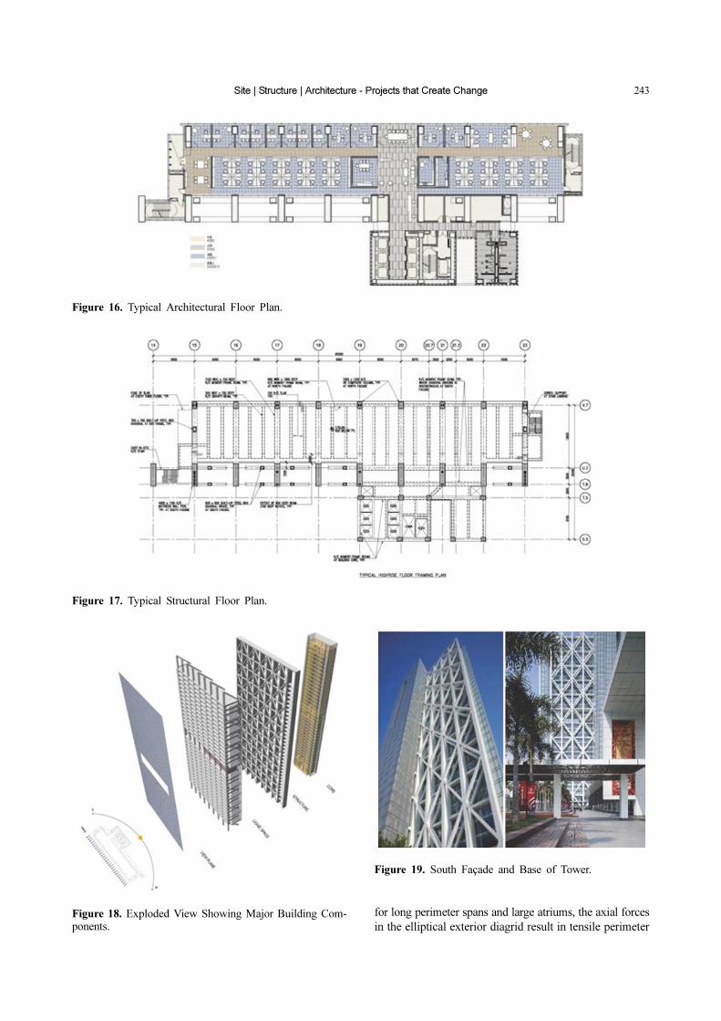
radial members to the core walls. The lateral axial force
distribution is shown in Fig. 26.
Suspended intermediate level floor diaphragms do not
connect to the perimeter diagrid frame and transfer all
their inertial seismic forces to the core walls. These diap-
hragm slabs thus act as in-plane cantilevers supported at
the face of the core walls. They are reinforced to transfer
horizontal seismic forces during the moderate earthquake
to the core walls without yielding. See Fig. 27 for the
concrete cone and diagrid frame under construction and
the finished building in Fig. 28.
Figure 26. Lateral Axial Force Distribution. Figure 27. Concrete Shear Wall within Diagrid Frame.
Figure 28. Finished Building Photograph.

Site | Structure | Architecture - Projects that Create Change 247
5. Conclusions, Opportunities, and the Future
Each of the Poly projects uniquely responded to their
sites and use while creating an integrated design solution.
Perhaps in the future projects will refer to this work for
new inspirations. See rendered elevation at based and
finished Poly International Plaza in Fig. 29. For instance,
exterior wall systems for structures represent the single
greatest opportunity to consider flow and interaction bet-
ween structure and building service systems. Hundreds of
millions of square feet of occupied area are enclosed each
year by a system that essentially provides protection from
the elements and internal comfort. A closed loop structural
system integrated with the exterior wall system that inc-
ludes liquid-filled structural elements such as pipes could
provide a thermal radiator that when heated during the
day could be used for building service systems such as
hot water supply or heat for occupied spaces, especially
during the evening hours. A solar collection system could
be integrated into the network and incorporated into dou-
ble wall systems where it can be used to heat the internal
cavity in cold climates. See Figs. 30 and 31.
Transparent photovoltaic cells could be introduced into
the glass and spandrel areas to further capture the energy
Figure 29. Rendered Elevation at Building Base and Finished Building.
Figure 30. Exploded View of Integrated Systems.

248 Leo Chow et al. | International Journal of High-Rise Buildings
of the sun. When storing fluid in structural systems of
great height, pressures within the networked vessel bec-
ome very large. With this level of pressure, water supply
systems to the structure or to neighboring structures of
lesser height could easily be supplied without requiring
additional energy to move the water. Constant low flow
through these systems would prevent the liquid from
freezing.
Liquid within the networked system could act to cont-
rol motion with fluid flow acting to dampen the structure
when subjected to lateral loads due wind and earthquake
events. In addition, liquids at high pressure could add sig-
nificantly to the axial stiffness and stability of structural
members subjected to compression, increasing capacities
without increasing structural material by creating capped
compartments. Combining ultra-high strength tensile ma-
terials such as carbon fiber fabricated into closed circular
forms where loads are primarily resisted by hoop stress
with the liquids under ultra-high compressive stress would
likely result in greatest efficiency in resisting applied load.
The concept of flow can be further developed into
structures that are interactively monitored for movement.
Through the measurement of imposed accelerations due
to ground motions or wind, structures could respond by
changing the state of the liquid within the system. For
instance, the structure could use endothermic reactions to
change liquids to solids within the closed network. Sensor
devices could inform structural elements of imminent
demand and initiate a state change in liquids that would
be subjected to high compressive loads where buckling
could occur. In the simplest sense, water within the system
could be frozen for additional structural rigidity.
For example, the Poly International Plaza, Beijing,
China, offers a unique insight into towers of the future.
The structure makes significant steps in the direction of
the most advanced technologies. Because of significant
levels of seismicity and the concern for life-cycle seismic
performance, concrete was used in the exterior tubular
frame. In the future, however, this framed system could
be utilized for a fully integrated approach where structure,
architecture, and mechanical systems are completely syn-
ergetic.
The study of these emerging forms as they interact with
the architecture (overtly or covertly) will only yield fur-
ther opportunities to explore light, space, structure and a
new relationship that combines them all in an ephemeral
solution. The investigation into the flow of material that
can be manipulated to adhere to a seismic, temperature or
safety condition can only inform us of new ways to design
and build.
References
Janssen, Jules J. A. (1991). Mechanical Properties of Bam-
boo, Springer Science+Business Media B.V., Dordrecht,
Netherlands.
Mitchell, A. G. M. (1904). “The Limits of Economy of Mat-
erial in Frame Structures.” Philosophical Magazine, 8(6),
pp. 589-597.
Sarkisian, M., Mathias, N., Garai, R., Hachem, M., and
Deierlein, G. (2010). “Pine Fuse Systems-Limiting Struc-
tural Damage in Major Seismic Events Using Friction
Fuses.” Proceedings SEAOC Convention.
Figure 31. Internal Column-Free Space.
![The Importance of Culture: Building and Sustaining Effective Engineering Organizations [QCon Beijing 2014]](https://cdn.vdocument.in/doc/165x107/53f8cdb38d7f7253318b48aa/the-importance-of-culture-building-and-sustaining-effective-engineering-organizations-qcon-beijing-2014.jpg)


