
CHAP T E R
6
Database Design using the E-R
Model
Solutions for the Pra ti e Exer ises of Chapter 6
Pra ti e Exer ises
6.1
Answer:
One possible E-R diagram is shown in Figure 6.101. Payments are modeled as
weak entities sin e they are related to a spe i� poli y.
Note that the parti ipation of a ident in the relationship parti ipated is not
total, sin e it is possible that there is an a ident report where the parti ipating
ar is unknown.
customer
customer_id
name
address
owns
participated
car
license_no
model
accident
report_id
date
place
payment
policy
policy_idcovers1 . . 11 . . *
premium_ payment
payment_no
due_date
amount
received_on
Figure 6.101 E-R diagram for a ar insuran e ompany.
35

36 Chapter 6 Database Design using the E-R Model
student
student_id
name
dept_name
tot_cred
course
course_id
title
credits
section
sec_id
semester
year
exam_marks sec_course
exam
exam_id
name
place
time
marks
Figure 6.102 E-R diagram for marks database.
6.2
Answer:
a. The E-R diagram is shown in Figure 6.102. Note that an alternative is to
model examinations as weak entities related to a se tion, rather than as
strong entities. The marks relationship would then be a binary relation-
ship between student and exam, without dire tly involving se tion.
b. The E-R diagram is shown in Figure 6.103. Note that here we have not
modeled the name, pla e, and time of the exam as part of the relationship
attributes. Doing so would result in dupli ation of the information, on e
per student, and we would not be able to re ord this information without
an asso iated student. If we wish to represent this information, we need
to retain a separate entity orresponding to ea h exam.
6.3
Answer:
The diagram is shown in Figure 6.104. The derived attribute season s ore is
omputed by summing the s ore values asso iated with the player entity set via
the played relationship set.
student
student_id
name
dept_name
tot_cred
course
course_id
title
credits
section
sec_id
semester
year
exam_marks sec_course
{exam_marks
exam_id
marks
}
Figure 6.103 Another E-R diagram for marks database.

Pra ti e Exer ise 37
played
player
player_id
nameage
season_score()
score
match
match_id
date
stadium
opponent
own_score
opp_score
Figure 6.104 E-R diagram for favorite team statisti s.
6.4
Answer:
The reason an entity set would appear more than on e is if one is drawing a
diagram that spans multiple pages.
The di�erent o urren es of an entity set may have di�erent sets of at-
tributes, leading to an in onsistent diagram. Instead, the attributes of an entity
set should be spe i�ed only on e. All other o urren es of the entity should
omit attributes. Sin e it is not possible to have an entity set without any at-
tributes, an o urren e of an entity set without attributes learly indi ates that
the attributes are spe i�ed elsewhere.
6.5
Answer:
a. If a pair of entity sets are onne ted by a path in an E-R diagram, the
entity sets are related, though perhaps indire tly. A dis onne ted graph
implies that there are pairs of entity sets that are unrelated to ea h other.
In an enterprise, we an say that the two parts of the enterprise are om-
pletely independent of ea h other. If we split the graph into onne ted
omponents, we have, in e�e t, a separate database orresponding to ea h
independent part of the enterprise.
b. As indi ated in the answer to the previous part, a path in the graph be-
tween a pair of entity sets indi ates a (possibly indire t) relationship be-
tween the two entity sets. If there is a y le in the graph, then every pair
of entity sets on the y le are related to ea h other in at least two distin t
ways. If the E-R diagram is a y li , then there is a unique path between
every pair of entity sets and thus a unique relationship between every pair
of entity sets.

38 Chapter 6 Database Design using the E-R Model
6.6
Answer:
a. Let E = ^e
1
, e
2
`, A = ^a
1
, a
2
`, B = ^b
1
`, C = ^
1
`, R
A
=
^(e
1
, a
1
), (e
2
, a
2
)`, R
B
= ^(e
1
, b
1
)`, and R
C
= ^(e
1
,
1
)`. We see that
be ause of the tuple (e
2
, a
2
), no instan e of A,B,C, and R exists that or-
responds to E, R
A
, R
B
and R
C
.
b. See Figure 6.105. The idea is to introdu e total parti ipation onstraints
between E and the relationships R
A
, R
B
, R
C
so that every tuple in E has a
relationship with A, B, and C.
. Suppose A totally parti ipates in the relationhip R, then introdu e a total
parti ipation onstraint between A and R
A
, and similarly for B and C.
6.7
Answer:
The primary key of a weak entity set an be inferred from its relationship with
the strong entity set. If we add primary-key attributes to the weak entity set, they
will be present in both the entity set, and the relationship set and they have to
be the same. Hen e there will be redundan y.
6.8
Answer:
In this example, the primary key of se tion onsists of the attributes ( ourse id,
se id, semester, year), whi h would also be the primary key of se ourse, while
ourse id is a foreign key from se ourse referen ing ourse. These onstraints
ensure that a parti ular se tion an only orrespond to one ourse, and thus the
many-to-one ardinality onstraint is enfor ed.
However, these onstraints annot enfor e a total parti ipation onstraint, sin e
a ourse or a se tion may not parti ipate in the se ourse relationship.
6.9
A
EB CR
BR
AR
C
Figure 6.105 E-R diagram for Exer ise Exer ise 6.6b.

Pra ti e Exer ise 39
Answer:
In addition to de laring s ID as primary key for advisor, we de lare i ID as a
superkey for advisor (this an be done in SQL using the unique onstraint on
i ID).
6.10
Answer:
The foreign-key attribute in R orresponding to the primary key of B should be
made not null. This ensures that no tuple of A whi h is not related to any entry
in B under R an ome in R. For example, say a is a tuple in A whi h has no
orresponding entry in R. This means when R is ombined with A, it would have
a foreign-key attribute orresponding to B as null, whi h is not allowed.
6.11
Answer:
a. For the many-to-many ase, the relationship set must be represented as a
separate relation that annot be ombined with either parti ipating entity.
Now, there is no way in SQL to ensure that a primary-key value o urring
in an entity E1 also o urs in a many-to-many relationship R, sin e the
orresponding attribute in R is not unique; SQL foreign keys an only
refer to the primary key or some other unique key.
Similarly, for the one-to-many ase, there is no way to ensure that an at-
tribute on the one side appears in the relation orresponding to the many
side, for the same reason.
b. Let the relation R be many-to-one from entity A to entity B with a and b as
their respe tive primary keys. We an put the following he k onstraints
on the "one" side relation B:
onstraint total part he k (b in (sele t b from A));
set onstraints total part deferred;
Note that the onstraint should be set to deferred so that it is only he ked
at the end of the transa tion; otherwise if we insert a b value in B before
it is inserted in A, the onstraint would be violated, and if we insert it in
A before we insert it in B, a foreign-key violation would o ur.
6.12
Answer:
A inherits all the attributes of X, plus it may de�ne its own attributes. Similarly,
C inherits all the attributes of Y plus its own attributes. B inherits the attributes
of both X and Y. If there is some attribute name whi h belongs to both X and Y,
it may be referred to in B by the quali�ed name X.name or Y.name.
40 Chapter 6 Database Design using the E-R Model
6.13
Answer:
.
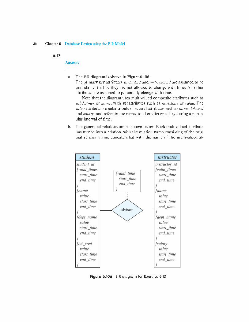
a. The E-R diagram is shown in Figure 6.106.
The primary key attributes student id and instru tor id are assumed to be
immutable, that is, they are not allowed to hange with time. All other
attributes are assumed to potentially hange with time.
Note that the diagram uses multivalued omposite attributes su h as
valid times or name, with subattributes su h as start time or value. The
value attribute is a subattribute of several attributes su h as name, tot red
and salary, and refers to the name, total redits or salary during a parti -
ular interval of time.
b. The generated relations are as shown below. Ea h multivalued attribute
has turned into a relation, with the relation name onsisting of the orig-
inal relation name on atenated with the name of the multivalued at-
student
student_id
{valid_times
start_time
end_time
}
{name
value
start_time
end_time
}
{dept_name
value
start_time
end_time
}
{tot_cred
value
start_time
end_time
}
instructor
instructor_id
{valid_times
start_time
end_time
}
{name
value
start_time
end_time
}
{dept_name
value
start_time
end_time
}
{salary
value
start_time
end_time
}
advisor
{valid_time
start_time
end_time
}
Figure 6.106 E-R diagram for Exer ise 6.13

Pra ti e Exer ise 41
tribute. The relation orresponding to the entity has only the primary-key
attribute, and this is needed to ensure uniqueness.
student(student id)
student valid times(student id, start time, end time)
student name(student id, value, start time, end time
student dept name(student id, value, start time, end time
student tot red(student id, value, start time, end time
instru tor(instru tor id)
instru tor valid times(instru tor id, start time, end time)
instru tor name(instru tor id, value, start time, end time
instru tor dept name(instru tor id, value, start time, end time
instru tor salary(instru tor id, value, start time, end time
advisor(student id, instru tor id, start time, end time)
The primary keys shown are derived dire tly from the E-R diagram. If we
add the additional onstraint that time intervals annot overlap (or even
the weaker ondition that one start time annot have two end times), we
an remove the end time from all the above primary keys.


