
www.danelec.com
MT-4E Analog and P25 Digital Radio SystemsMAINTENANCE GUIDE


MG-001 Daniels MT-4E Radio Systemswww.danelec.com
i
Mainte-nance Guide
Daniels MT-4EAnalog and P25 Digital
Radio Systems
Maintenance Guide

MG-001 Daniels MT-4E Radio Systemswww.danelec.com
ii
Mainte-nanceGuide
Copyright © 2009 Daniels Electronics Ltd. All rights reserved. No part of this publication may be reproduced, stored in a retrieval system or transmitted in any form or by any means, electronic, mechanical, photocopying, recording or otherwise, without the prior written consent of Daniels Electronics Ltd.
The stylized “Daniels Electronics Ltd.” and “DE” logo are registered Canadian and US trademarks of Daniels Electronics Ltd.The stylized “Daniels Electronics Ltd.” and “DE” logo are trademarks of Daniels Electronics Ltd.IMBE™ is a trademark of Digital Voice Systems, Inc.Motorola® is a registered trademark of Motorola, Inc.
NOTE
Daniels Electronics Ltd. utilizes a three-level revision system. This system enables Daniels to identify the signifi cance of a revision. Each element of the revision number signifi es the scope of change as described in the diagram below.
DOCUMENT REVISION DEFINITION
Major Revisions: The result of a major change to product function, process or
requirements.
Minor Revisions: The result of a minor change to product, process or
requirements.
Editorial Revisions: The result of typing corrections or changes in formatting,
grammar or wording.
1-0-0
Three-level revision numbers start at 1-0-0 for the fi rst release. The appropriate element of the revision number is incremented by 1 for each subsequent revision, causing any digits to the right to be reset to 0.
For example:If the current revision = 2-1-1 Then the next major revision = 3-0-0If the current revision = 4-3-1 Then the next minor revision = 4-4-0If the current revision = 3-2-2 Then the next editorial revision = 3-2-3
Daniels Electronics Ltd.43 Erie Street, Victoria, BCCanada V8V [email protected]
Toll Free Canada and USA:phone: 1-800-664-4066fax: 1-877-750-0004
International:phone: 250-382-8268fax: 250-382-6139
PRINTED IN CANADA
Document Number:Revision:
Revision Date:
MG-0014-0-0December 2009

MG-001 Daniels MT-4E Radio Systemswww.danelec.com
iii
Mainte-nance Guide
For the past 60 years Daniels has provided customers in North America and internationally with highly reliable Base Stations and Repeaters that are environmentally robust to operate in rugged and extreme temperature conditions where low current consumption (solar powered) is a key requirement.
Daniels has been a pioneering member of the P25 Digital standard, for radio system interoperability between emergency response governmental organizations, providing enhanced functionality and encryption. Our products operate between 29 - 869 MHz and are available in a variety of Base Station and Repeater confi gurations for two way voice and mobile data applications.
Our self-servicing customers range from Forestry and National Park services through Police and Fire departments and on to Utility and Transportation groups. Our products have been deployed in every imaginable situation from the Antarctic to Hawaiian mountaintops to Alaska, enabling respondents to Forest Fires, Ground Zero rescue and routine patrols.
Daniels is an industry leader in Analog and P25 radio systems design. We offer modular rack-mounted Base Stations and Repeaters capable of operating in the following bands:
Low Band VHF VHF AM VHF FM UHF FM800 MHz
ABOUT DANIELS ELECTRONICS LTD.
MG-001 Daniels MT-4E Radio Systemswww.danelec.com
iv
Mainte-nanceGuide
Daniels Electronics Ltd. provides many resources for the testing, tuning, maintenance and design of your Daniels MT-4E Analog and P25 Digital Radio System.
Instruction Manuals
Daniels Electronics instruction manuals are very comprehensive and include information on:
Theory of operationDetailed Specifi cationsTesting and tuning instructionsComponent layout illustrations
Instruction manuals can be obtained from the factory.
Technical Notes
Technical notes outline key aspects of tuning, installing, maintaining and servicing Daniels P25 Radio Systems.
Technical Notes can be found online at www.danelec.com.
Daniels MT-4R/D and IFR 2975 Test Procedures (TN950)
Technical Note TN950 is an aid to confi guring and testing Daniels MT-4R/D radios using an IFR 2975 Service Monitor by Aerofl ex. TN950 is intended to be used with IFR 2975 Setup fi les that can be loaded into the Service Monitor.
TN950 and the Setup Files can be found online at www.danelec.com and can also be found on the Aerofl ex web page at www.p25.com.
Application Notes
Application Notes provide an overview of the range of applications in which Daniels P25 Radio equipment can be used.
Application Notes can be found online at www.danelec.com.
P25 Training Guide
The P25 Training Guide provides the reader with a simple, concise and informative description of Project 25.
The P25 Training Guide can be found online at www.danelec.com.
MT-4E Analog and P25 Digital Radio Systems User Guide
The MT-4E User Guide provides an overview of the confi guration, operation and programming of Daniels MT-4E radios.
The MT-4E User Guide can be found online at www.danelec.com.
RESOURCES

MG-001 Daniels MT-4E Radio Systemswww.danelec.com
v
Mainte-nance Guide
ContentsChapter 1: Daniels Radio Maintenance ................................1
Introduction to Daniels MT-4E ....................................................................1Recommended Maintenance Schedule .....................................................2Repair Note ................................................................................................2ESD - Electrostatic Discharge ....................................................................2Audio and Carrier Levels Reference ..........................................................3
Audio Levels ...................................................................................................3Carrier Levels .................................................................................................3
Chapter 2: Installation ............................................................5Installation of Daniels Subrack ...................................................................5
Chapter 3: Test Equipment and Spares .................................9Recommended Test Equipment .................................................................9Recommended Spares ............................................................................ 10Recommended Maintenance Items ......................................................... 11
Chapter 4: Radio Site Survey .............................................. 13Introduction to a Radio Site Survey ......................................................... 13
Daniels Radio Site Checklist and Inventory ...................................................13Preparation for a Site Survey ................................................................... 14Exterior Site Survey ................................................................................. 15Interior Site Survey .................................................................................. 15Radio Site Inventory ................................................................................. 15Radio System Testing .............................................................................. 16Departure Checklist ................................................................................. 16

MG-001 Daniels MT-4E Radio Systemswww.danelec.com
vi
Mainte-nanceGuide
Chapter 5: Daniels Radio System Testing ........................... 17MT-4E Testing with the IFR 2975 by Aerofl ex .......................................... 17General Set-Up and Connections ............................................................ 18
Uploading Daniels Confi gurations to the IFR 2975 .......................................18Radio Service Software (RSS) ......................................................................18Control Cards ................................................................................................18Adapters, Cables and Extender Cards ..........................................................19Audio Connections ........................................................................................19Daniels MT-4E Radio System Test Sheet ......................................................19
System Regulator Testing ........................................................................ 20System Voltage Testing .................................................................................20
Receiver Testing ....................................................................................... 21Receiver Analog Testing ................................................................................21Receiver Digital Testing .................................................................................26Receiver Bit Error Rate Testing .....................................................................28Receiver RF Preselector Alignment and Tuning ............................................30Receiver Reference Oscillator Adjustment ....................................................32
Transmitter Testing ................................................................................... 35Transmitter Analog Testing ............................................................................35Transmitter CTCSS Testing ...........................................................................40Transmitter Digital Testing .............................................................................43Transmitter Modulation Fidelity Testing .........................................................45Transmitter Reference Oscillator Adjustment ................................................47
System Testing ......................................................................................... 49Duplex Analog Testing ...................................................................................49Duplex Digital Testing ....................................................................................52
Chapter 6: Additional Radio System Tests ........................... 55Radio System Testing Through Filtering Equipment ................................ 56Radio System Testing with the Antenna Connected ................................ 57
VSWR ............................................................................................................57Receiver Desense .........................................................................................58RF Carrier Signal Levels on Links between Sites .........................................59Spurious Signals over the Air ........................................................................60
Chapter 7: Blank Worksheets .............................................. 61
MG-001 Daniels MT-4E Radio Systemswww.danelec.com
Chapter 1: Daniels Radio Maintenance 1
Mainte-nance Guide
This document is written as a maintenance guide to Daniels Electronics Ltd. MT-4E Analog and P25 Digital Radio Systems. The document assumes the reader is familiar with conventional Two-Way Radio Communications systems and general electronics maintenance practices. This document is a companion document to the Daniels Electronics Ltd. MT-4E Analog and P25 Digital Radio Systems User Guide.
INTRODUCTION TO DANIELS MT-4E
Daniels MT-4E radio systems are designed for operation in highly varied conditions. Your application may require high performance radio systems (intermodulation and selectivity) for operation in congested radio sites, operation over wide temperatures using battery solar powered systems (low current drain), or a confi gurable system for emergency deployment in a transportable case. Daniels manufactures a diverse range of radio products tailored to the type of operation you need.
The MT-4E radio system is characterized by high performance and reliability, whether it is a remote, low current repeater or a high performance base station. The total system is designed to provide dependable, low maintenance performance and great fl exibility for expansion and servicing.
The MT-4E series of radio and control modules are packaged in the compact Eurostandard housing with anodized aluminum front panels, and are ruggedly designed for remote or transportable applications. All of the modules use high reliability components and corrosion resistant fasteners.
The MT-4E radio system is specifi cally designed to deliver high performance under adverse conditions. Voltage stress testing and a 24 hour burn-in is performed on the radio system and performance of the system at room temperature (25°C) is documented and measured. As an option, extensive environmental testing can be conducted over the temperature range - 30°C to + 60°C and the performance measured to ensure compliance with the design specifi cations.
A Daniels MT-4E radio system consists of separate RF receiver and transmitter modules plugged into a standard 19” subrack. Each subrack also requires a control card and system regulator. External connections to the system (COR, PTT, audio, channel select, etc.) are made through an auxiliary connector on the rear of the subrack. An optional cable or terminal strip connector is available to connect externally through the auxiliary connector to the radio system.
CHAPTER 1: DANIELS RADIO MAINTENANCE

MG-001 Daniels MT-4E Radio Systemswww.danelec.com
Chapter 1: Daniels Radio Maintenance2
Mainte-nanceGuide
RECOMMENDED MAINTENANCE SCHEDULE
Daniels Electronics does not recommend any specifi c maintenance schedule for our MT-4E radio systems. Many organizations have annual preventative maintenance scheduled as part of their standard maintenance procedures; other organizations will only maintain the radio system when a system failure occurs; and other organizations will use a combination of preventative maintenance and maintenance for failures.
REPAIR NOTE
The MT-4E Radio System employs a high percentage of surface mount components which should not be removed or replaced using an ordinary soldering iron. Removal and replacement of surface mount components should be performed only with specifi cally designed surface mount rework and repair stations complete with Electrostatic Discharge (ESD) protection. When removing Surface Mount Solder Jumpers, it is recommended to use solder wick braid in place of vacuum type de-soldering tools. This will help prevent damage to the circuit boards.
ESD - ELECTROSTATIC DISCHARGE
Static Electricity can damage electronic equipment, causing it to stop functioning immediately, or degrading it, leading to breakdown later. Static sensitive parts should be handled by technicians grounded with wrist and/or two heel straps. Transferring of ESD sensitive components to or from different areas should be conducted in ESD safe bags, tote boxes or carts.

MG-001 Daniels MT-4E Radio Systemswww.danelec.com
Chapter 1: Daniels Radio Maintenance 3
Mainte-nance Guide
AUDIO AND CARRIER LEVELS REFERENCE
The following are conversions for both audio levels and RF carrier levels.
Audio Levels
2.500 Vrms 6.928 Vpp +10 dBm (@ 600 ohms)
0.975 Vrms 2.758 Vpp +2 dBm
0.775 Vrms 2.191 Vpp 0 dBm
0.388 Vrms 1.098 Vpp -6 dBm
0.308 Vrms 0.872 Vpp -8 dBm
0.245 Vrms 0.692 Vpp -10 dBm
0.098 Vrms 0.276 Vpp -18 dBm
0.077 Vrms 0.219 Vpp -20 dBm
Carrier Levels
70.71 uV -70 dBm (@ 50 ohms)
0.707 uV -110 dBm
0.398 uV -115 dBm
0.354 uV -116 dBm
0.316 uV -117 dBm
0.282 uV -118 dBm
0.251 uV -119 dBm
0.224 uV -120 dBm
0.199 uV -121 dBm
0.178 uV -122 dBm
0.158 uV -123 dBm

MG-001 Daniels MT-4E Radio Systemswww.danelec.com
4
Mainte-nanceGuide
This Page Intentionally Left Blank

MG-001 Daniels MT-4E Radio Systemswww.danelec.com
Chapter 2: Installation 5
Mainte-nance Guide
CHAPTER 2: INSTALLATION
INSTALLATION OF DANIELS SUBRACK
1. Ensure the 19” rack has enough room for the Daniels subrack to be installed. Each Daniels subrack requires 5 1/4” height (3 RU) and 13.5” (maximum) depth clearances.
2. Install the subrack unit(s) in the 19” rack using four #10 x 3/4” screws as shown in Figure 2-1. Eight screw holes are available, only four screws are required to mount the subrack properly. Use stainless steel screws if the equipment is to be placed in a corrosive environment.
Figure 2-1: Subrack Installation
#10 x 3/4”screws

MG-001 Daniels MT-4E Radio Systemswww.danelec.com
Chapter 2: Installation6
Mainte-nanceGuide
3. Connect the primary power (+10 Vdc to +17 Vdc, +13.8 Vdc nominal) to the Barrier Strip power input on the rear of the subrack as shown in Figure 2-2. Ensure that the power source does not exceed +18 Vdc. Use a wire gauge suitable for delivering the power required by the subrack(s). If the subrack is using a DC-DC or AC-DC Power Supply, refer to the specifi c manual supplied with the equipment for installation instructions.
Reverse voltage protection and over voltage protection (transient suppressor) is provided at the main power (+13.8 Vdc) input as well as the +9.5 Vdc line. The main power input is protected with a standard fast-blow 15 amp fuse. These components may require replacing if the power supply is not connected properly, or even after a power surge or a lightning strike. The two transient suppressors have different voltage ratings for the main power input and +9.5 Vdc lines.
4. Install the System Regulator, Receiver, Transmitter, Power Amplifi er and Control Card modules in to the subrack using the proper guide rail slots if not already done. When installing modules, ensure the quick release fasteners on the top and the bottom of the modules are in the unlocked (slot should be horizontal) position before insertion to the guide rails. To lock the quick release fasteners, push and turn the fastener 90 degrees clockwise with a fl at screwdriver.
Note: MT-4E modules may be removed or inserted from the subrack while power is supplied without damaging the equipment.
5. Interconnect +9.5 Vdc and +13.8 Vdc power between subrack units if one of the subracks does not include a system regulator (no system regulator is required for a second subrack with only power amplifi ers mounted in it). If a CI-RC-4M Multiple Link Controller is part of the system, connect the +9.5 Vdc from the subrack to the controller.
Figure 2-2: Subrack Power Connections
Power Input+10 to +17 Vdc
+13.8 Vdc Nominal
+9.5 Vdc RegulatedPower Input / Output
(used for interconnecting 2 subracks or powering
CI-RC-4M)
P1 Auxiliary Connector
FuseReverse and Over Voltage
Protection

MG-001 Daniels MT-4E Radio Systemswww.danelec.com
Chapter 2: Installation 7
Mainte-nance Guide
6. If an external controller (eg. Vega tone-remote adapter) is to be connected to the system, all wiring should be made to the DB25 connector or to the optional screw-type A-PNL-AUX96-3 auxiliary terminal connector shown in Figure 2-3.
The female DB25 connector can be used for basic base connections to a Vega DSP-223 or IP-223, using a standard straight-through male-to-male DB25 cable.
WARNING: JU108 must be confi gured correctly for DSP-223 or IP-223 or damage can occur. JU108 A for +13.8 Vdc / DSP-223 or JU108 B for Rx A COR / IP-223
The plug in screw connectors on the A-PNL-AUX96-3 can be removed to allow for easy connection of the wires.
For some applications, a cable, not a terminal strip connector, is used to connect to the auxiliary connector. The cable must be plugged into the P1 auxiliary connector shown in Figure 2-2 on the rear of the subrack. Ensure locking tabs on the connector are completely engaged.
Figure 2-3: Auxiliary Terminal Connector
7. Connect the RJ45 cables between the Receiver, Transmitter and Control Card for repeater operation.
8. Connect the RF cables to the Receiver and Transmitter and ensure they are fi rmly screwed on. Ensure the RF cables are properly connected to the Duplexer / Antenna Relay / Multicoupler / Combiner and Antenna.
A-PNL-AUX96-3 optional screw-type auxiliary terminal connector
Telex / Vega CI-DSP-223or CI-IP-223connector

MG-001 Daniels MT-4E Radio Systemswww.danelec.com
8
Mainte-nanceGuide
This Page Intentionally Left Blank
MG-001 Daniels MT-4E Radio Systemswww.danelec.com
Chapter 3: Test Equipment and Spares 9
Mainte-nance Guide
CHAPTER 3: TEST EQUIPMENT AND SPARES
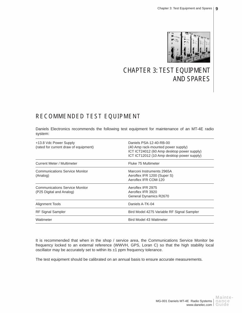
RECOMMENDED TEST EQUIPMENT
Daniels Electronics recommends the following test equipment for maintenance of an MT-4E radio system:
+13.8 Vdc Power Supply Daniels PSA-12-40-RB-00 (rated for current draw of equipment) (40 Amp rack-mounted power supply) ICT ICT24012 (60 Amp desktop power supply) ICT ICT12012 (10 Amp desktop power supply)
Current Meter / Multimeter Fluke 75 Multimeter
Communications Service Monitor Marconi Instruments 2965A(Analog) Aerofl ex IFR 1200 (Super S) Aerofl ex IFR COM-120
Communications Service Monitor Aerofl ex IFR 2975(P25 Digital and Analog) Aerofl ex IFR 3920 General Dynamics R2670
Alignment Tools Daniels A-TK-04
RF Signal Sampler Bird Model 4275 Variable RF Signal Sampler
Wattmeter Bird Model 43 Wattmeter
It is recommended that when in the shop / service area, the Communications Service Monitor be frequency locked to an external reference (WWVH, GPS, Loran C) so that the high stability local oscillator may be accurately set to within its ±1 ppm frequency tolerance.
The test equipment should be calibrated on an annual basis to ensure accurate measurements.

MG-001 Daniels MT-4E Radio Systemswww.danelec.com
Chapter 3: Test Equipment and Spares10
Mainte-nanceGuide
RECOMMENDED SPARES
Daniels Electronics recommends one complete radio system spare for every ten radio systems (or less) in operation to account for lightning damage or other maintenance issues. The amount of spares could be dependant on the critical nature of the radio system and the availability of service for the system. Daniels recommends a complete radio system spare for every critical / essential site in the system. The design of Daniels Electronics Ltd. MT-4E radio systems makes it easy to swap components of a radio system and can save valuable time and effort during maintenance. The exact spares would depend on the types of systems in operation, but would typically include:
Subrack / Motherboard SR-39-1
System Regulator SM-3-H0-014-00 (Standard) SM-3-H0-R1N-00 (with single antenna relay) SM-3-H0-R2N-00 (with dual antenna relays)
Control Card CI-RC-4L (Repeater Control Card) CI-BC-4E (Base Control Card) CI-RC-4M (Multiple Link Controller)
Receiver VR-4E150-A0-000 (136 - 174 MHz Class A) UR-4E420-A0-000 (406 - 430 MHz Class A) UR-4E460-A0-000 (450 - 470 MHz Class A) VR-4E150-00-000 (136 - 174 MHz Class B) UR-4E420-00-000 (406 - 430 MHz Class B) UR-4E460-00-000 (450 - 470 MHz Class B) UR-4E500-00-000 (470 - 520 MHz Class B) UR-4E800-00-000 (806 - 824 MHz Class B) UR-4E850-00-000 (851 - 869 MHz Class B)
Transmitter VT-4E150-00-800 (136 - 174 MHz) UT-4E450-00-800 (406 - 470 MHz) UT-4E500-00-800 (470 - 520 MHz) UT-4E850-00-300 (799 - 869 MHz)
Amplifi er AMP-2/150-30-00 (VHF 30 Watts) AMP-2/450-30-00 (UHF 30 Watts)
Auxiliary Connector A-PNL-AUX96-3

MG-001 Daniels MT-4E Radio Systemswww.danelec.com
Chapter 3: Test Equipment and Spares 11
Mainte-nance Guide
RECOMMENDED MAINTENANCE ITEMS
Daniels Electronics recommends the following maintenance items at each radio site:
A-TK-04 MT-4 Tool Kit
EC-48RD 48 pin Direct Connect Extender
EC-96D1 96 pin Direct Connect Extender
5059-TP110300 Test Points (included with all extender cards)
Additional extender kits can also be located at the radio shop:
EC-48RK-1.22 48 pin Extender Kit with cable
EC-96K-1.22 96 pin Extender Kit with cable
Items included in the MT-4 Tool Kit include:
5192-WJ01BJ01 SMB to BNC Jack Adapter
7910-WP0WP012 SMB to SMB Cable
2007-1N637500 10V Transient Suppressor
2007-1N637800 18V Transient Suppressor
2001-MR751000 Reverse Voltage Diode (Qty=2)
5604-5GAGC150 15 Amp Fast-Blow Fuse
CBLC46-12506050 50 cm RJ45 Cable
Radio Service Software (RSS)
APP-RSS03-WC-XX Radio Service Software for programming and service of the Receiver and Transmitter modules.
CBLC44-20704305 type A to 5 pin mini-type B USB cable to connect from computer to Receiver or Transmitter.

MG-001 Daniels MT-4E Radio Systemswww.danelec.com
12
Mainte-nanceGuide
This Page Intentionally Left Blank

MG-001 Daniels MT-4E Radio Systemswww.danelec.com
Chapter 4: Radio Site Survey 13
Mainte-nance Guide
CHAPTER 4: RADIO SITE SURVEY
INTRODUCTION TO A RADIO SITE SURVEY
Radio sites (repeaters, base stations, etc.) can be located in remote locations and require extensive travel to visit. Remote radio sites could require helicopter transportation, be motor vehicle accessible, or even require travel by horseback in order to reach them. Typically when visiting these sites it is a good idea to perform a site survey to document and inspect the site for possible damage (weather related, vandalism, wildlife), and general maintenance of the site. Radio sites that are not remote can also benefi t greatly from a site survey.
A site survey is a valuable tool in the preventative maintenance of the radio site. Documenting site condition, inventory and radio system operation on each visit can highlight action that is needed and allows the technician to prepare for subsequent visits.
While every site is different and many organizations may have their own procedures for site surveys, this chapter can be used as a general outline for a radio site survey.
Daniels Radio Site Checklist and InventoryA Daniels Radio Site Checklist and a Daniels Radio Site Inventory is included in Chapter 7 of this Maintenance Guide. It is recommended that the checklist and inventory be fi lled out each time the radio site is visited.

MG-001 Daniels MT-4E Radio Systemswww.danelec.com
Chapter 4: Radio Site Survey14
Mainte-nanceGuide
PREPARATION FOR A SITE SURVEY
When preparing for a site survey, remember to bring the following items:
• Communications Service Monitor
• Multimeter
• Spare radio equipment
• Standard tool box with wire strippers, screwdrivers, crimper, etc.
• Extra RF cabling to replace any damaged cables
• Adapters (N Type to BNC, etc.)
• Extender cards for radio maintenance
• Daniels A-TK-04 Tool Kit
Optional Items:
• Paper, pens and pencils for documenting
• Soldering Iron, solder and de-soldering tool
• Portable radio
• Survival gear, food and drink
• Camera for photographing site condition
• Keys for the buildings / gates
• Documentation for the radio system (manuals, diagrams, previous site survey / inventory)
• Wildlife deterrent (pepper spray)
Check that all test equipment and spare radio equipment is operational and tuned to the correct frequency for that site.
Be aware of all applicable safety measures and regulations for working at, and travelling to and from a radio site (eg. does anyone know where you are going and when you are expected back?).

MG-001 Daniels MT-4E Radio Systemswww.danelec.com
Chapter 4: Radio Site Survey 15
Mainte-nance Guide
EXTERIOR SITE SURVEY
When fi rst arriving at the radio site, an external survey of the site and surrounding area should be conducted to identify any hazards. Actions or repairs that may be required for this or the next site survey can also be identifi ed.
• Check that the building is in good condition (no cracks, leaks, vandalism or other damage)
• Check the antennas, and antenna structure (tower) for visible damage
• Check the external RF cables and connectors for visible damage or corrosion
• Check the external leased lines and / or power cables for damage
• Check the lightning protection for damage
• Check that there are no obstructions in the area (branches, overgrown brush, etc.)
• Exterior site photographs can be taken
INTERIOR SITE SURVEY
Once the radio site is entered an interior survey of the site should be conducted.
• Check the interior of the building, including the fl oor, for water leaks, animal entry or other damage
• Check the condition of the cabinet / equipment rack
• Check the internal RF cables and connectors for visible damage or corrosion
• Check the duplexers / combiners / multicouplers for damage, loose parts or corrosion
• Check the internal leased lines and / or power cables for damage
• Check the power supply / batteries / solar panels and ensure they are operating correctly
• Interior site photographs can be taken
RADIO SITE INVENTORY
It is a good idea to fi ll out a complete inventory of all model numbers and serial numbers of the radio equipment, duplexers, antennas, power supplies and all other equipment at the site when performing a site survey. Use the Daniels Radio Site Inventory to record this information. Daniels Electronics Ltd.suggests that customers maintain a site inventory, as serial and model numbers can help the factory with any customer support issues.

MG-001 Daniels MT-4E Radio Systemswww.danelec.com
Chapter 4: Radio Site Survey16
Mainte-nanceGuide
RADIO SYSTEM TESTING
Test the radio system as detailed in Chapter 5 and 6 of this Maintenance Guide. Chapter 5 includes detailed testing information on the Daniels radio system using an IFR 2975 test set, and Chapter 6 includes information on additional tests that can be performed on a complete radio system at the radio site.
DEPARTURE CHECKLIST
It is extremely important to perform a fi nal departure check before leaving the radio site.
• Check the RF cables, fi ltering system and antenna system to ensure it is all connected properly, and that the RF connectors are all fi rmly in place on all equipment
• Check that the power supply is turned on, connected, and operational
• Check that the switches on the Receiver and Transmitter are in the NORM position and the System Regulator speaker switch is OFF (turning the LED on the System Regulator OFF), and any other additional switches are in the correct position
• Ensure that the RJ45 interconnection cables are plugged in (if used)
• Check that the building lights are turned off, tower lights are turned on and any other lights are set correctly
• Perform a radio check on air with a portable radio and have another user verify the radio operation (dispatcher / operator)
• Check that the door is closed and locked

MG-001 Daniels MT-4E Radio Systemswww.danelec.com
Chapter 5: Daniels Radio System Testing 17
Mainte-nance Guide
CHAPTER 5: DANIELS RADIO SYSTEM TESTING
MT-4E TESTING WITH THE IFR 2975 BY AEROFLEX
This Chapter contains instructions for Tuning, Testing, Maintaining and Servicing MT-4E Analog and P25 Digital Radio Systems with the IFR 2975 by Aerofl ex.
This Chapter is intended as an aid to confi guring and testing Daniels MT-4E radios using an IFR 2975 Service Monitor by Aerofl ex. Neither Daniels Electronics Ltd. or Aerofl ex Inc. assume responsibility for damage caused to either unit as a result of misinterpretation or misuse of this procedure. Daniels manufactured products are warranted against defective materials and workmanship. This warranty does not extend to damage due to misuse, neglect, accident, improper confi guration or installation. Daniels and Aerofl ex shall be released from all obligations under its respective warranty in the event the Products are subject to misuse, neglect, alteration, accident, improper installation or testing, or if unauthorized repairs are performed by the customer or others.
These procedures can be modifi ed, changed and altered at any time to better suit your specifi c needs and requirements. The alarm points set in the IFR 2975 test set do not necessarily refl ect a radio system that is not operating to specifi cation. Refer to Daniels Electronics Instruction Manuals for complete radio system specifi cations.

MG-001 Daniels MT-4E Radio Systemswww.danelec.com
Chapter 5: Daniels Radio System Testing18
Mainte-nanceGuide
GENERAL SET-UP AND CONNECTIONS
Uploading Daniels Confi gurations to the IFR 2975The IFR 2975 allows for confi guration fi les to be saved and recalled on the test set. These confi guration fi les are uploaded to the test set from a fl oppy disk and can also be uploaded from your computer if the test set is connected to your network.
Firmware version 1.8.1 or higher is required on your IFR 2975 to use these confi guration fi les. To check the fi rmware version of the IFR 2975, go to System (7) then Version (3). If Version 1.8.1 or higher is not installed in the IFR 2975, go to www.P25.com for the latest update. On some fi rmware versions, the fi les would be recalled with the MOD TYPE off. Update the fi rmware version or remember to turn the MOD TYPE to FM or P25 after recalling a setup.
The IFR 2975 confi guration fi les are available from Daniels website at www.danelec.com. The fi le can be downloaded, then unzipped and copied onto a fl oppy disk or transferred onto the network. If a Daniels directory already exists on your IFR 2975 (for MT-4R/D testing), rename that directory or it will be overwrittwen by the MT-4E Daniels directory.
To upload a fi le from a fl oppy disk, insert the fl oppy disk into the drive and go to System (7) then Save / Recall Setups (6). Click on the BACKUP SETUPS button on the right hand side of the screen. In the window that opens, click on the BACKUP TO button and select RESTORE FROM fl oppy. This will download the Daniels directory to the internal drive of your IFR 2975.
The recalled setups could affect some of the System Confi guration settings on the IFR 2975 (such as the 10 MHz reference selection). You may need to change and re-save these saved fi les depending on your system confi guration (eg. if you are using an EXTERNAL 10 MHz reference).
Please note that some of the setups that are recalled are generic and may need to be changed for your specifi c receiver and transmitter settings.
The generic saved setups are as follows:Audio = 1000 Hz @ 1.5 KHz deviation (for wideband set this to 3.0 KHz deviation)CTCSS = 100.0 Hz @ 0.35 KHz deviation (for wideband set this to 0.5 KHz deviation)NAC = 293TGID = 1
Radio Service Software (RSS)Start the RSS program on the computer and ensure you are connected to the receiver or transmitter via the type A to 5 pin mini-type B USB cable. Read the transmitter or receiver programming and familiarize yourself with the settings (RF frequency, wide / narrowband, digital / analog, CTCSS / NAC, etc.).
Control CardsSome Daniels MT-4E radio systems may have an AC-3E Audio Control Card or CI-BC-4E Base Control Card for use in the radio system. The Control Cards connect to the receiver and transmitter balanced audio lines with an unbalanced load, which could cause some measurements to be in error. If the radio system includes an AC-3E Audio Control Card or CI-BC-4E Base Control Card, remove the control card from the rack for the individual receiver and transmitter tests unless otherwise noted.

MG-001 Daniels MT-4E Radio Systemswww.danelec.com
Chapter 5: Daniels Radio System Testing 19
Mainte-nance Guide
Adapters, Cables and Extender CardsVarious adapters, cables and extender cards are required for the different radio tests. Extender cards and adapters are available from Daniels Electronics. The receiver reference oscillator and RF preselector fi lter tests require an SMB - BNC adapter and a small SMB - SMB cable is required for the reference oscillator test as well. The SMB adapters and cables are included in the A-TK-04 Tool Kit.
Audio ConnectionsThe Receiver, Transmitter and Auxiliary Balanced audio lines are available for connection on Daniels extender cards or by connecting to the optional back panel A-PNL-AUX96-3 screw-type terminal connector. The extender cards have solder points available on each signal line that can have a small test point, (5059-TP110300) that is supplied with the extender card, soldered to them for easy connection with clip-on type clips. Recommended Test Points are:
Audio Control Card and Base Control Card Extender Card pins (EC-96D1 and EC-96K-1.22):Auxiliary 1 Audio Output = B11 and A11Auxiliary 2 Audio Output = C1 and C3 (Audio Control Card); C2 and C4 (Base Control Card)Auxiliary 1 Audio Input = C19 and C20Auxiliary 2 Audio Input = B14 and A14
Receiver and Transmitter Extender Card pins (EC-48RD and EC-48RK-1.22):Rx Balanced Audio Output = B26 and Z26Tx Balanced Audio Input = B18 and Z18Tx Subtone Input = B22 and Ground (B32)
The test points can be soldered into the extender cards as shown in Figure 5-1.
Figure 5-1: EC-96D1 and EC-48RD Direct Connect Extender Cards with Test Points Added
Daniels MT-4E Radio System Test SheetA Daniels MT-4E Radio System Test Sheet is included in Chapter 7 of this Maintenance Guide. It is recommended that this test sheet be fi lled out each time the radio system is tested. If two or more pairs of transceivers are tested, use a second test sheet to record the results. The test sheet will record settings for a single Tx and Rx frequency, however other frequencies can be tested and recorded if desired.
test points soldered onto extender card

MG-001 Daniels MT-4E Radio Systemswww.danelec.com
Chapter 5: Daniels Radio System Testing20
Mainte-nanceGuide
SYSTEM REGULATOR TESTING
System Voltage TestingThe fi rst stage of testing a Daniels MT-4E radio system is to perform a basic system check on the supply and regulated voltages. The System Regulator module is designed with a convenient and easy test point built into the front panel. This test point allows a technician access to the DC supply and regulated voltages. Simply connect a standard Digital Volt Meter (DVM) to the METER jacks on the front panel of the System Regulator as shown in Figure 5-2.
Figure 5-2: System Regulator Voltage Testing
The FUNCTION rotary switch on the front panel of the System Regulator will allow you to test various points in the radio system. Following is a list of System Regulator rotary switch positions, the functions they measure and the parameters measured:
1 Supply Voltage +10 Vdc to +17 Vdc (+13.8 Vdc nominal)
2 +9.5 Volts Regulated +9.5 Vdc (± 0.1 Vdc)
3 Rx A Audio Receiver A Audio (NOT Rx Balanced Output)
4 Rx A Carrier Strength 0 Vdc to +5.0 Vdc based on received signal strength (0 Vdc is a low RF signal level, +5.0 Vdc is high)
5 Rx B Audio Receiver B Audio (NOT Rx Balanced Output)
6 Rx B Carrier Strength 0 Vdc to +5.0 Vdc based on received signal strength (0 Vdc is a low RF signal level, +5.0 Vdc is high)
Enter the Supply Voltage and +9.5 Volts Regulated values on the MT-4E Test Sheet and inject a -100 dBm carrier signal into the Receiver and record the RSSI Voltage on the MT-4E Test Sheet. Enter the Date, Firmware Versions and Serial numbers of the Receivers and Transmitters on the MT-4E Test Sheet. The Firmware Version and Serial Number can be found by connecting the RSS and clicking on Rx ID or Tx ID. The Serial Numbers can also be found on the side of the modules.
The standby current draw of the radio system should be measured for battery / solar powered systems. Connect an ammeter to the power input line and measure the standby current draw and transmit current draw of the system. Enter the Standby Current Draw and Transmit Current Draw readings on the MT-4E Test Sheet. The maximum standby and transmit current draw is dependent on the radio system (number and class of receivers, transmitter output power, amplifi ers, auxiliary equipment, etc.).
VOL
2
1
5
4
3
678
11
10
9
SYSTEM REGULATORFUNCTION
METER
+
-
12
MADE IN CANADA
DANIELSELECTRONICS LTD.
ONOFF
SPKRINTEXT
EXT
SPKR
MIN MAXHOLD REL
% msHz RANGE
dB
dB
ac+dc
ac+dc
ac+dc
ac+dc
F
nS
mA
mAA
mV
V
mV
V
OFF
C
A
A
A
A mA COM V
TEMPERATURE
A
MIN MAXHOLD REL
% msHz RANGE
dB
dB
ac+dc
ac+dc
ac+dc
ac+dc
F
nS
mA
mAA
mV
V
mV
V
OFF
C
A
A
A
A mA COM V
TEMPERATURE
A
AutoHOLD LOGGING
SAVECANCEL
FAST MN MX
SETUP
YES
NO
DIGITAL MULTIMETER
CLEAR MEMVIEW
DC
REPEATERCONTROL
RX B
TX B
RX A
TX A
CI-RC-4L PULL DOWNTO REMOVE
9
5
3
711
15
9
13
3
711
15
SWITCH A SWITCH B
TRANSMITTER
CNTLBUS
MIC RF OUT
A D
ANALOGDIGITAL
NORMOFFKEY TX
MICMODE
DANIELSELECTRONICS LTD.
REFIN
USB
FREQUENCY (MHz)
MADE IN CANADAMODEL # CODE
RECEIVER
NORM
SQ. DISABLE
OFF
CNTLBUS
A D
RF NI
DANIELSELECTRONICS LTD.
REFIN
USB
FREQUENCY (MHz)
MADE IN CANADAMODEL # CODE

MG-001 Daniels MT-4E Radio Systemswww.danelec.com
Chapter 5: Daniels Radio System Testing 21
Mainte-nance Guide
RECEIVER TESTING
Receiver Analog TestingConnect the IFR 2975 and Daniels Radio as shown in Figure 5-3:
Figure 5-3: Receiver Analog Testing
On the IFR 2975, recall Daniels setup 1 (Rx_Ana) from your internal drive. Enter the correct RF frequency and ensure that the deviation level of the 1.0 KHz tone is set correctly for your receiver (wide / narrow). Enter the correct CTCSS tone (if used) and deviation level for the tone. On the Daniels Radio system, ensure the receiver is turned on and turn the System Regulator Speaker switch to ON and INT. Set the FUNCTION rotary switch to position 3 for Rx A or position 5 for Rx B (depending on the receiver being tested), then turn the volume up until the 1 KHz tone is audible.
In the Jumper Settings area of the Service section on the RSS, ensure that the “Subtones on audio path” selection is set to “Don’t pass” as shown in Figure 5-4. The IFR 2975 will conduct all tests with CTCSS tones on the audio, giving erroneous measurements, if the Subtones are set to “Pass”.
Figure 5-4: RSS Subtone Settings
Rx Balanced Audio Output(from pins B26 and Z26)
Computer running RSS
USB fromComputer to Rx
T/R port from IFR 2975 to RF IN on Rx
HELP MODE
TAB
SHIFT
+
-
.
BKSP
HOLD
RETURN
ESC ENTER POWER
1 2ABC
3DEF
JKL MNOGHI654
TUV WXYZPQRS987
#0*
VOLUME
SQUELCH
GEN T/R ANT
125 W MAXMIC AUDIO I/ODVMCH2CH1SCOPETEST PORT
100V MAX 100V MAX 100V MAX
AUDIO IN AUDIO OUT 1 AUDIO OUT 2
Audio InRECEIVER
NORM
SQ. DISABLE
OFF
CNTLBUS
A D
RF NI
DANIELSELECTRONICS LTD.
REFIN
USB
FREQUENCY (MHz)
MADE IN CANADAMODEL # CODE
VOL
2
1
5
4
3
678
11
10
9
SYSTEM REGULATORFUNCTION
METER
+
-
12
MADE IN CANADA
DANIELSELECTRONICS LTD.
ONOFF
SPKRINTEXT
EXT
SPKR

MG-001 Daniels MT-4E Radio Systemswww.danelec.com
Chapter 5: Daniels Radio System Testing22
Mainte-nanceGuide
Audio Distortion:
To check receiver distortion, inject -70 dBm RF carrier level into the receiver and measure the distortion on the meter as shown in Figure 5-5. The High Alarm is set to 2.0 %.
Figure 5-5: Receiver Distortion Measurement
Enter the Audio Distortion reading on the MT-4E Test Sheet.
MG-001 Daniels MT-4E Radio Systemswww.danelec.com
Chapter 5: Daniels Radio System Testing 23
Mainte-nance Guide
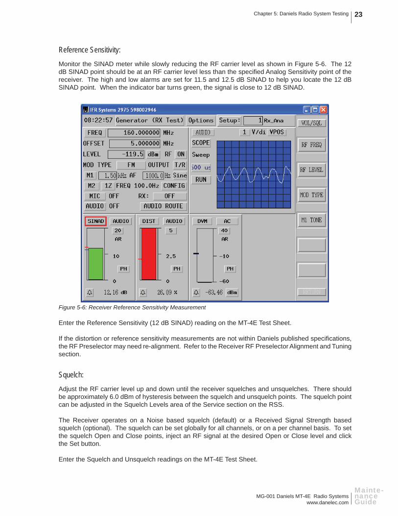
Reference Sensitivity:
Monitor the SINAD meter while slowly reducing the RF carrier level as shown in Figure 5-6. The 12 dB SINAD point should be at an RF carrier level less than the specifi ed Analog Sensitivity point of the receiver. The high and low alarms are set for 11.5 and 12.5 dB SINAD to help you locate the 12 dB SINAD point. When the indicator bar turns green, the signal is close to 12 dB SINAD.
Figure 5-6: Receiver Reference Sensitivity Measurement
Enter the Reference Sensitivity (12 dB SINAD) reading on the MT-4E Test Sheet.
If the distortion or reference sensitivity measurements are not within Daniels published specifi cations, the RF Preselector may need re-alignment. Refer to the Receiver RF Preselector Alignment and Tuning section.
Squelch:
Adjust the RF carrier level up and down until the receiver squelches and unsquelches. There should be approximately 6.0 dBm of hysteresis between the squelch and unsquelch points. The squelch point can be adjusted in the Squelch Levels area of the Service section on the RSS.
The Receiver operates on a Noise based squelch (default) or a Received Signal Strength based squelch (optional). The squelch can be set globally for all channels, or on a per channel basis. To set the squelch Open and Close points, inject an RF signal at the desired Open or Close level and click the Set button.
Enter the Squelch and Unsquelch readings on the MT-4E Test Sheet.

MG-001 Daniels MT-4E Radio Systemswww.danelec.com
Chapter 5: Daniels Radio System Testing24
Mainte-nanceGuide
Audio Level:
The audio level adjustment is not required when connecting the receiver in a repeater confi guration using LVDS Serial Data. The audio level adjustment can be done on both the Rx Balanced Audio Output and the Auxiliary Balanced Output (1 and 2). The Auxiliary Balanced Output is only available on the AC-3E Control Card or CI-BC-4E Base Control Card.
To adjust the receiver balanced audio output, ensure that the AC-3E Control Card or CI-BC-4E Base Control Card is NOT plugged into the subrack, disconnect the Rx Balanced audio output from the Audio Input of the IFR 2975 (audio box) and connect it to the DVM input directly on the IFR 2975 as shown in Figure 5-7 (no external load is required as the internal 600 ohm load of the IFR 2975 is used). Inject -70 dBm RF carrier level into the receiver.
Figure 5-7: Receiver Analog Audio Testing
In the Audio Levels area of the Service section on the RSS, adjust the Rx Balanced Audio Output level adjustment as shown in Figure 5-8 until -8.0 dBm audio level (0.308 Vrms @ 600 ohms) is measured on the DVM meter of the IFR 2975 as shown in Figure 5-9. The high and low alarms are set at -7.5 dBm and -8.5 dBm audio levels.
Figure 5-8: RSS Receiver Audio Level Adjustment
Rx Balanced Audio Output(from pins B26 and Z26)
Computer running RSS
USB fromComputer to Rx
T/R port from IFR 2975 to RF IN on Rx
HELP MODE
TAB
SHIFT
+
-
.
BKSP
HOLD
RETURN
ESC ENTER POWER
1 2ABC
3DEF
JKL MNOGHI654
TUV WXYZPQRS987
#0*
VOLUME
SQUELCH
GEN T/R ANT
125 W MAXMIC AUDIO I/ODVMCH2CH1SCOPETEST PORT
100V MAX 100V MAX 100V MAX
DVM port onIFR 2975
RECEIVER
NORM
SQ. DISABLE
OFF
CNTLBUS
A D
RF NI
DANIELSELECTRONICS LTD.
REFIN
USB
FREQUENCY (MHz)
MADE IN CANADAMODEL # CODE
VOL
2
1
5
4
3
678
11
10
9
SYSTEM REGULATORFUNCTION
METER
+
-
12
MADE IN CANADA
DANIELSELECTRONICS LTD.
ONOFF
SPKRINTEXT
EXT
SPKR

MG-001 Daniels MT-4E Radio Systemswww.danelec.com
Chapter 5: Daniels Radio System Testing 25
Mainte-nance Guide
Figure 5-9: Receiver Balanced (and Auxiliary) Audio Output Measurement
To adjust the auxiliary balanced audio output, plug the AC-3E Control Card or CI-BC-4E Base Control Card into the subrack using an extender card and connect the Auxiliary Balanced audio output to the DVM input directly on the IFR 2975 (no external load is required as the internal 600 ohm load of the IFR 2975 is used). Auxiliary 1 audio output is available on pins B11 and A11, and Auxiliary 2 audio output is available on pins C1 and C3 for the AC-3E Control Card and pins C2 and C4 for the CI-BC-4E Base Control Card. Ensure that NO external devices (eg. tone remote adapter or IP router) are connected to the auxiliary audio output. Adjust the Auxiliary Balanced Audio Output level adjustment (R13 for Aux Out 1, R56 for Aux Out 2) for 0.0 dBm audio level (0.775 Vrms @ 600 ohms).
Enter the Balanced Audio Output Level and Auxiliary Audio Output Level (if used) readings on the MT-4E Test Sheet.
There are no specifi c measurements to check Receive CTCSS, just verify that the receiver CTCSS is operating.

MG-001 Daniels MT-4E Radio Systemswww.danelec.com
Chapter 5: Daniels Radio System Testing26
Mainte-nanceGuide
Receiver Digital TestingConnect the IFR 2975 and Daniels Radio as shown in Figure 5-10.
Figure 5-10: Receiver Digital Testing
On the IFR 2975, recall Daniels setup 2 (Rx_Dig) from your internal drive. Enter the correct RF frequency, and ensure that the MOD TYPE is set to P25 and it is set for the SPEECH test pattern (or optionally the 1011 test pattern).
Rx Balanced Audio Output(from pins B26 and Z26)
Computer running RSS
USB fromComputer to Rx
T/R port from IFR 2975 to RF IN on Rx
HELP MODE
TAB
SHIFT
+
-
.
BKSP
HOLD
RETURN
ESC ENTER POWER
1 2ABC
3DEF
JKL MNOGHI654
TUV WXYZPQRS987
#0*
VOLUME
SQUELCH
GEN T/R ANT
125 W MAXMIC AUDIO I/ODVMCH2CH1SCOPETEST PORT
100V MAX 100V MAX 100V MAX
AUDIO IN AUDIO OUT 1 AUDIO OUT 2
Audio InRECEIVER
NORM
SQ. DISABLE
OFF
CNTLBUS
A D
RF NI
DANIELSELECTRONICS LTD.
REFIN
USB
FREQUENCY (MHz)
MADE IN CANADAMODEL # CODE
VOL
2
1
5
4
3
678
11
10
9
SYSTEM REGULATORFUNCTION
METER
+
-
12
MADE IN CANADA
DANIELSELECTRONICS LTD.
ONOFF
SPKRINTEXT
EXT
SPKR

MG-001 Daniels MT-4E Radio Systemswww.danelec.com
Chapter 5: Daniels Radio System Testing 27
Mainte-nance Guide
Inject the correct NAC (and TGID if programmed) and ensure that the receiver is operating as shown in Figure 5-11. There are no specifi c measurements to make on this test, just verify that the receiver is operating.
Figure 5-11: Receiver Digital Check
MG-001 Daniels MT-4E Radio Systemswww.danelec.com
Chapter 5: Daniels Radio System Testing28
Mainte-nanceGuide
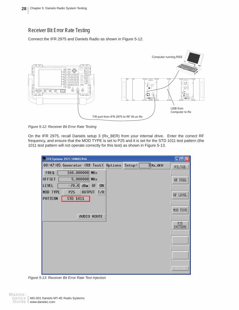
Receiver Bit Error Rate TestingConnect the IFR 2975 and Daniels Radio as shown in Figure 5-12.
Figure 5-12: Receiver Bit Error Rate Testing
On the IFR 2975, recall Daniels setup 3 (Rx_BER) from your internal drive. Enter the correct RF frequency, and ensure that the MOD TYPE is set to P25 and it is set for the STD 1011 test pattern (the 1011 test pattern will not operate correctly for this test) as shown in Figure 5-13.
Figure 5-13: Receiver Bit Error Rate Test Injection
Computer running RSS
USB fromComputer to Rx
T/R port from IFR 2975 to RF IN on Rx
HELP MODE
TAB
SHIFT
+
-
.
BKSP
HOLD
RETURN
ESC ENTER POWER
1 2ABC
3DEF
JKL MNOGHI654
TUV WXYZPQRS987
#0*
VOLUME
SQUELCH
GEN T/R ANT
125 W MAXMIC AUDIO I/ODVMCH2CH1SCOPETEST PORT
100V MAX 100V MAX 100V MAX
RECEIVER
NORM
SQ. DISABLE
OFF
CNTLBUS
A D
RF NI
DANIELSELECTRONICS LTD.
REFIN
USB
FREQUENCY (MHz)
MADE IN CANADAMODEL # CODE
VOL
2
1
5
4
3
678
11
10
9
SYSTEM REGULATORFUNCTION
METER
+
-
12
MADE IN CANADA
DANIELSELECTRONICS LTD.
ONOFF
SPKRINTEXT
EXT
SPKR

MG-001 Daniels MT-4E Radio Systemswww.danelec.com
Chapter 5: Daniels Radio System Testing 29
Mainte-nance Guide
In the receiver RSS, enter the Service section and click on “Bit Error Rate”. The receiver frequency should automatically be shown in the frequency box. Select the Test Type to “Continuous” and Average Frames to “8”. Click on the “Start Test” button to start the BER test. You should get 0% BER at the -70 dBm default RF carrier level.
Monitor the BER reading while slowly reducing the RF carrier level as shown in Figure 5-14. The 5% BER point should be at an RF carrier level less than the specifi ed Digital Sensitivity point of the receiver.
Figure 5-14: RSS Receiver Bit Error Rate Test
Enter the Reference Sensitivity (5% BER) reading on the MT-4E Test Sheet.
If the BER measurements are not within Daniels published specifi cations, the RF Preselector may need re-alignment. Refer to the Receiver RF Preselector Alignment and Tuning section.

MG-001 Daniels MT-4E Radio Systemswww.danelec.com
Chapter 5: Daniels Radio System Testing30
Mainte-nanceGuide
Receiver RF Preselector Alignment and TuningTuning of the RF Preselector fi lter is typically only required when the Analog or Digital Sensitivity or Analog Distortion do not meet published specifi cations, or when the receiver RF frequency is changed beyond the band pass of the fi lter (typically 5 - 7 MHz in a VHF or UHF 400 MHz receiver). The UHF 800 MHz receiver RF Preselector is Full Band and does not require any tuning.
Connect the IFR 2975 and Daniels Radio as shown in Figure 5-15.
Figure 5-15: Receiver RF Preselector Tuning
The RF Preselector output is a small RF cable internal in the receiver that terminates in an SMB connector. The SMB plugs into J3 on the Receiver Mainboard. Disconnect the SMB cable from J3 and use the SMB-BNC adapter to connect this point to the ANT input on the IFR 2975 as shown in Figure 5-16.
Figure 5-16: Receiver RF Preselector Connection
RF Preselector output from Receiverto ANT input on IFR 2975
T/R port from IFR 2975 to RF IN on Rx
HELP MODE
TAB
SHIFT
+
-
.
BKSP
HOLD
RETURN
ESC ENTER POWER
1 2ABC
3DEF
JKL MNOGHI654
TUV WXYZPQRS987
#0*
VOLUME
SQUELCH
GEN T/R ANT
125 W MAXMIC AUDIO I/ODVMCH2CH1SCOPETEST PORT
100V MAX 100V MAX 100V MAX
RECEIVER
NORM
SQ. DISABLE
OFF
CNTLBUS
A D
RF NI
DANIELSELECTRONICS LTD.
REFIN
USB
FREQUENCY (MHz)
MADE IN CANADAMODEL # CODE
VOL
2
1
5
4
3
678
11
10
9
SYSTEM REGULATORFUNCTION
METER
+
-
12
MADE IN CANADA
DANIELSELECTRONICS LTD.
ONOFF
SPKRINTEXT
EXT
SPKR
J3
To ANT input on IFR 2975
RF Preselector output

MG-001 Daniels MT-4E Radio Systemswww.danelec.com
Chapter 5: Daniels Radio System Testing 31
Mainte-nance Guide
On the IFR 2975, recall Daniels setup 4 (Rx_PreTune) from your internal drive. Enter the correct RF frequency and ensure the receiver is turned on. In the “Trace” box on the right hand side of the screen click on the “Run” button. The fi lter waveform should appear as shown in Figure 5-17. Click on Options then Confi gure Markers to add optional markers to the spectrum analyzer if desired.
Figure 5-17: Receiver RF Preselector on the Spectrum Analyzer
To tune the RF Preselector fi lter, remove the dust caps on the variable capacitors and, starting from the capacitor closest to the front panel of the receiver and moving back, tune the fi lter to its new frequency.

MG-001 Daniels MT-4E Radio Systemswww.danelec.com
Chapter 5: Daniels Radio System Testing32
Mainte-nanceGuide
Receiver Reference Oscillator AdjustmentConnect the IFR 2975 and Daniels Radio as shown in Figure 5-18.
Figure 5-18: Receiver Reference Oscillator Testing
The reference oscillator test on the receiver requires a connection directly into the Synthesizer, which uses an SMB connector. Disconnect the SMB cable from the LO output of the synthesizer and connect the small SMB-SMB cable to the SMB jack that is mounted on the Synthesizer (beneath the RF Preselector). The SMB-BNC adapter is required to connect this point to the ANT input on the IFR 2975 as shown in Figures 5-19 (VHF and UHF 400 MHz Receiver) and 5-20 (UHF 800 MHz Receiver).
Figure 5-19: VHF and UHF 400 MHz Receiver Reference Oscillator Connection
Synthesizer L.O. output from Receiverto ANT input on IFR 2975
Computer running RSS
USB fromComputer to Rx
HELP MODE
TAB
SHIFT
+
-
.
BKSP
HOLD
RETURN
ESC ENTER POWER
1 2ABC
3DEF
JKL MNOGHI654
TUV WXYZPQRS987
#0*
VOLUME
SQUELCH
GEN T/R ANT
125 W MAXMIC AUDIO I/ODVMCH2CH1SCOPETEST PORT
100V MAX 100V MAX 100V MAX
RECEIVER
NORM
SQ. DISABLE
OFF
CNTLBUS
A D
RF NI
DANIELSELECTRONICS LTD.
REFIN
USB
FREQUENCY (MHz)
MADE IN CANADAMODEL # CODE
VOL
2
1
5
4
3
678
11
10
9
SYSTEM REGULATORFUNCTION
METER
+
-
12
MADE IN CANADA
DANIELSELECTRONICS LTD.
ONOFF
SPKRINTEXT
EXT
SPKR
To ANT input on IFR 2975
SMB-SMB cable
LO output of synthesizer

MG-001 Daniels MT-4E Radio Systemswww.danelec.com
Chapter 5: Daniels Radio System Testing 33
Mainte-nance Guide
Figure 5-20: UHF 800 MHz Receiver Reference Oscillator Connection
On the IFR 2975, recall Daniels setup 5 (Rx_Ref) from your internal drive as shown in Figure 5-21.
Figure 5-21: Receiver Reference Oscillator Measurement
To ANT input on IFR 2975
SMB-SMB cable
LO output of synthesizer

MG-001 Daniels MT-4E Radio Systemswww.danelec.com
Chapter 5: Daniels Radio System Testing34
Mainte-nanceGuide
In the receiver RSS, enter the Service section and click on “Ref Oscillator”. The reference oscillator frequency is shown as the “Target Synthesizer RF OUT”. Enter this RF frequency into the IFR 2975. The receiver generates this frequency out of the Synthesizer into the IFR 2975.
Monitor the RF Error window on the IFR 2975. To change the reference frequency, adjust the softpot slider in the RSS as shown in Figure 5-22. Adjust until the RF error is as close to 0 Hz as possible. Click on the “Program” button to program in the new Reference Oscillator softpot value. The high and low alarms are turned off.
Figure 5-22: RSS Receiver Reference Oscillator Alignment
Enter the L.O. Reference Oscillator Offset reading on the MT-4E Test Sheet.

MG-001 Daniels MT-4E Radio Systemswww.danelec.com
Chapter 5: Daniels Radio System Testing 35
Mainte-nance Guide
TRANSMITTER TESTING
Transmitter Analog TestingConnect the IFR 2975 and Daniels Radio as shown in Figure 5-23.
Figure 5-23: Transmitter Analog Testing
On the IFR 2975, recall Daniels setup 6 (Tx_Ana) from your internal drive. Enter the correct RF frequency on the IFR 2975, set the MIC MODE switch on the front panel of the transmitter to Analog, and fl ip the other switch to KEY TX (or set the switch to NORM and key the transmitter through the RSS).
FGEN1 is confi gured to inject a 1.0 KHz tone at -8.0 dBm (0.308 Vrms) into the transmitter balanced input.
Tx Balanced Audio Input(to pins B18 and Z18)
Computer running RSS
USB fromComputer to Tx
Tx RF OUT to T/R port on IFR 2975
HELP MODE
TAB
SHIFT
+
-
.
BKSP
HOLD
RETURN
ESC ENTER POWER
1 2ABC
3DEF
JKL MNOGHI654
TUV WXYZPQRS987
#0*
VOLUME
SQUELCH
GEN T/R ANT
125 W MAXMIC AUDIO I/ODVMCH2CH1SCOPETEST PORT
100V MAX 100V MAX 100V MAX
AUDIO IN AUDIO OUT 1 AUDIO OUT 2
AudioOut 1
TRANSMITTER
CNTLBUS
MIC RF OUT
A D
ANALOGDIGITAL
NORMOFFKEY TX
MICMODE
DANIELSELECTRONICS LTD.
REFIN
USB
FREQUENCY (MHz)
MADE IN CANADAMODEL # CODE
VOL
2
1
5
4
3
678
11
10
9
SYSTEM REGULATORFUNCTION
METER
+
-
12
MADE IN CANADA
DANIELSELECTRONICS LTD.
ONOFF
SPKRINTEXT
EXT
SPKR

MG-001 Daniels MT-4E Radio Systemswww.danelec.com
Chapter 5: Daniels Radio System Testing36
Mainte-nanceGuide
Audio Distortion:
The distortion meter will read demodulated audio and give you a transmitter distortion reading as shown in Figure 5-24. The High Alarm is set to 3.0 %.
Figure 5-24: Transmitter Distortion and Power Measurements
Enter the Audio Distortion reading on the MT-4E Test Sheet.

MG-001 Daniels MT-4E Radio Systemswww.danelec.com
Chapter 5: Daniels Radio System Testing 37
Mainte-nance Guide
RF Power:
Monitor the RF power output of the transmitter as shown in Figure 5-24. In the Power Level area of the Service section on the RSS, click on the “Key Tx” button and adjust the Transmitter Output Power adjustment as shown in Figure 5-25 to change the RF output power. The High Alarm is set at 8.5 Watts and the Low Alarm is set at 0.5 Watts. Transmitter RF power output will vary slightly with the +10 - +17 Vdc input.
Figure 5-25: RSS Transmitter Power Level Adjustment
Enter the RF Power Output reading on the MT-4E Test Sheet.
Connect the transmitter to the power amplifi er (if used) and measure the RF power output of the amplifi er. Daniels 30 Watt Amplifi er’s RF power output can be changed by adjusting the transmitter (exciter) RF power output. Do not exceed power amplifi er input levels. Higher power amplifi ers typically have a fi xed RF power input level and RF power output level.
Enter the Amplifi er RF Power Output reading on the MT-4E Test Sheet.

MG-001 Daniels MT-4E Radio Systemswww.danelec.com
Chapter 5: Daniels Radio System Testing38
Mainte-nanceGuide
Deviation Level:
The deviation level adjustment is not required when connecting the transmitter in a repeater confi guration using LVDS Serial Data. The audio level / deviation level adjustment can be done on both the Tx Balanced Audio Input and the Auxiliary Balanced Input (1 and 2). The Auxiliary Balanced Input is only available on the AC-3E Control Card or CI-BC-4E Base Control Card.
Change the Audio Filter (below DEMOD) from BANDPASS to 15 KHz LP as shown in Figure 5-26 for a more accurate deviation reading without CTCSS encode. If the transmitter has CTCSS encode, leave the Audio Filter on BANDPASS.
To adjust the transmitter balanced input, ensure that the AC-3E or CI-BC-4E Control Card is NOT plugged into the subrack. FGEN1 is confi gured to inject a 1.0 KHz tone at -8.0 dBm (0.308 Vrms) into the Tx Balanced audio input.
Figure 5-26: Transmitter Deviation Measurement

MG-001 Daniels MT-4E Radio Systemswww.danelec.com
Chapter 5: Daniels Radio System Testing 39
Mainte-nance Guide
In the Audio Levels area of the Service section on the RSS, click on the “Key Tx” button and adjust the Tx Balanced Audio Input level adjustment as shown in Figure 5-27 until a deviation of +/- 1.5 KHz (narrowband) or +/-3.0 KHz (wideband) is measured on the IFR 2975. The high and low alarms are set at +/-1.4 KHz to +/- 1.6 KHz deviation.
Figure 5-27: RSS Transmitter Audio Level Adjustment
Enter the Transmitter Deviation Level reading on the MT-4E Test Sheet.
Confi gure FGEN1 to inject a 300 Hz tone at +10.0 dBm (2.500 Vrms) into the Tx Balanced audio input and adjust the audio frequency from 300 Hz to 3400 Hz in increments of 100 Hz and check that the transmitter deviation does not rise above +/- 2.5 KHz (narrowband) or +/-5.0 KHz (wideband). The MT-4E Transmitter will transmit a maximum deviation at an audio frequency of approximately 1300 Hz.
Enter the Transmitter Maximum Deviation Level reading on the MT-4E Test Sheet.
To adjust the auxiliary balanced audio input, plug the AC-3E Control Card or CI-BC-4E Base Control Card into the subrack using an extender card, disconnect the Tx Balanced audio input and connect the Auxiliary Balanced audio input to the Audio Out 1 on the IFR 2975 (audio box). Auxiliary 1 audio input is available on pins C19 and C20, and Auxiliary 2 audio input is available on pins B14 and A14. Ensure that NO external devices (eg. tone remote adapter or IP router) are connected to the auxiliary audio input. Confi gure FGEN1 to inject a 1.0 KHz tone at 0.0 dBm (0.775 Vrms) into the Auxiliary Balanced audio input. Adjust the Auxiliary Balanced Audio Input level adjustment (R120 for Aux In 1, R123 for Aux In 2) for deviation of +/- 1.5 KHz (narrowband) or +/-3.0 KHz (wideband). The high and low alarms are set at +/-1.4 KHz to +/- 1.6 KHz deviation.
Enter the Auxiliary Deviation Level (if used) reading on the MT-4E Test Sheet.

MG-001 Daniels MT-4E Radio Systemswww.danelec.com
Chapter 5: Daniels Radio System Testing40
Mainte-nanceGuide
Transmitter CTCSS TestingMT-4E Transmitters can be programmed, per channel, to generate CTCSS tones internally, or to allow for External Input of the CTCSS tones from another device (such as a tone-remote adapter).
Connect the IFR 2975 and Daniels Radio as shown in Figure 5-28. The Tx Subtone input connection is only required when testing the External Input. If the internal programming is used to generate the CTCSS tone, disconnect the Tx Subtone input from the IFR 2975.
Figure 5-28: Transmitter CTCSS Testing
On the IFR 2975, recall Daniels setup 7 (Tx_CTCSS) from your internal drive. Enter the correct RF frequency on the IFR 2975, set the MIC MODE switch on the front panel of the transmitter to Analog and fl ip the other switch to KEY TX (or set the switch to NORM and key the transmitter through the RSS).
Computer running RSS
USB fromComputer to Tx
Tx RF OUT to T/R port on IFR 2975
HELP MODE
TAB
SHIFT
+
-
.
BKSP
HOLD
RETURN
ESC ENTER POWER
1 2ABC
3DEF
JKL MNOGHI654
TUV WXYZPQRS987
#0*
VOLUME
SQUELCH
GEN T/R ANT
125 W MAXMIC AUDIO I/ODVMCH2CH1SCOPETEST PORT
100V MAX 100V MAX 100V MAX
TRANSMITTER
CNTLBUS
MIC RF OUT
A D
ANALOGDIGITAL
NORMOFFKEY TX
MICMODE
DANIELSELECTRONICS LTD.
REFIN
USB
FREQUENCY (MHz)
MADE IN CANADAMODEL # CODE
Tx Subtone Input (to pins B22 and Ground (B32))
AUDIO IN AUDIO OUT 1 AUDIO OUT 2
AudioOut 1
VOL
2
1
5
4
3
678
11
10
9
SYSTEM REGULATORFUNCTION
METER
+
-
12
MADE IN CANADA
DANIELSELECTRONICS LTD.
ONOFF
SPKRINTEXT
EXT
SPKR

MG-001 Daniels MT-4E Radio Systemswww.danelec.com
Chapter 5: Daniels Radio System Testing 41
Mainte-nance Guide
FGEN1 (if used) is confi gured to inject a 100 Hz tone at -18.0 dBm (0.098 Vrms or 0.277 Vpp) into the Tx Subtone input as shown in Figure 5-29. If the internal programming is used to generate the CTCSS tone, FGEN1 is not used and the CTCSS tone is generated internally in the transmitter.
Figure 5-29: Transmitter CTCSS Tone and Deviation Measurement
MG-001 Daniels MT-4E Radio Systemswww.danelec.com
Chapter 5: Daniels Radio System Testing42
Mainte-nanceGuide
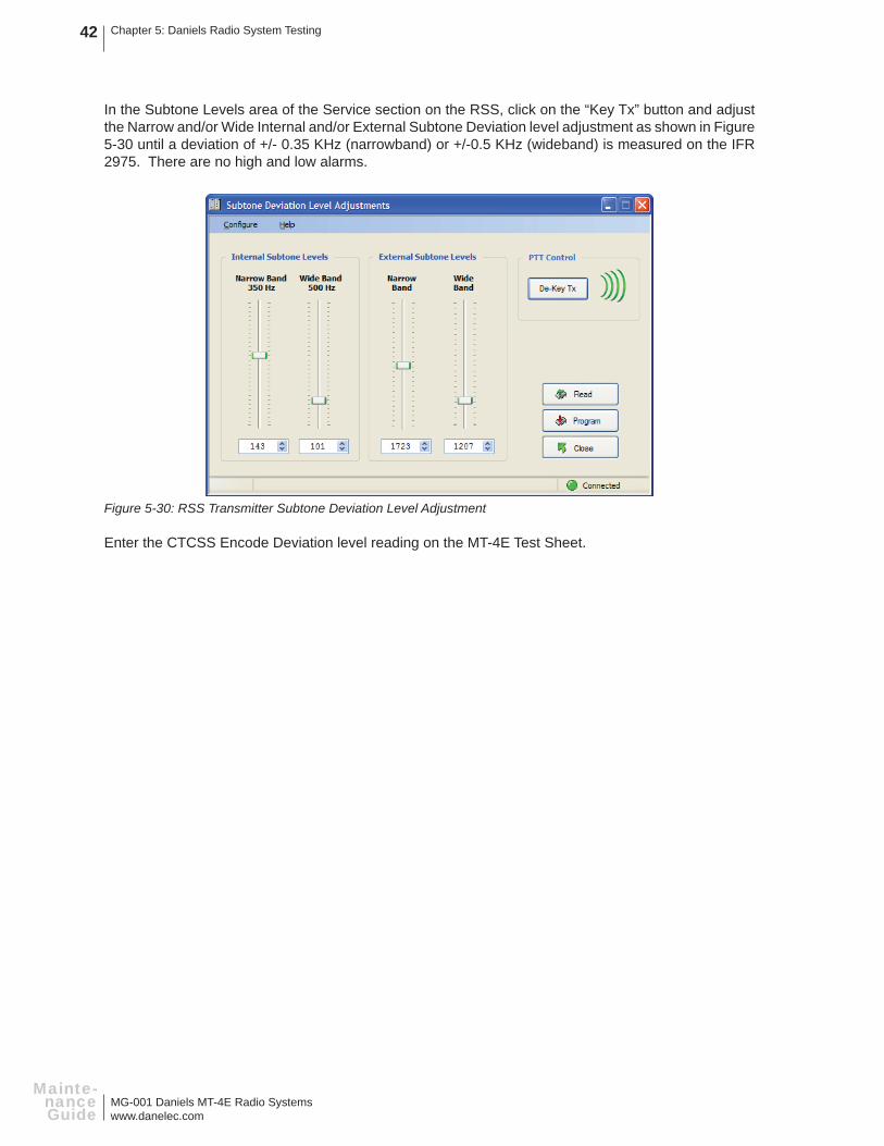
In the Subtone Levels area of the Service section on the RSS, click on the “Key Tx” button and adjust the Narrow and/or Wide Internal and/or External Subtone Deviation level adjustment as shown in Figure 5-30 until a deviation of +/- 0.35 KHz (narrowband) or +/-0.5 KHz (wideband) is measured on the IFR 2975. There are no high and low alarms.
Figure 5-30: RSS Transmitter Subtone Deviation Level Adjustment
Enter the CTCSS Encode Deviation level reading on the MT-4E Test Sheet.

MG-001 Daniels MT-4E Radio Systemswww.danelec.com
Chapter 5: Daniels Radio System Testing 43
Mainte-nance Guide
Transmitter Digital TestingConnect the IFR 2975 and Daniels Radio as shown in Figure 5-31.
Figure 5-31: Transmitter Digital Testing
On the IFR 2975, recall Daniels setup 8 (Tx_Dig) from your internal drive. Enter the correct RF frequency on the IFR 2975, set the MIC MODE switch on the front panel of the transmitter to Digital and fl ip the other switch to KEY TX (or set the switch to NORM and key the transmitter through the RSS).
Tx Balanced Audio Input(to pins B18 and Z18)
Computer running RSS
USB fromComputer to Tx
Tx RF OUT to T/R port on IFR 2975
HELP MODE
TAB
SHIFT
+
-
.
BKSP
HOLD
RETURN
ESC ENTER POWER
1 2ABC
3DEF
JKL MNOGHI654
TUV WXYZPQRS987
#0*
VOLUME
SQUELCH
GEN T/R ANT
125 W MAXMIC AUDIO I/ODVMCH2CH1SCOPETEST PORT
100V MAX 100V MAX 100V MAX
AUDIO IN AUDIO OUT 1 AUDIO OUT 2
AudioOut 1
TRANSMITTER
CNTLBUS
MIC RF OUT
A D
ANALOGDIGITAL
NORMOFFKEY TX
MICMODE
DANIELSELECTRONICS LTD.
REFIN
USB
FREQUENCY (MHz)
MADE IN CANADAMODEL # CODE
VOL
2
1
5
4
3
678
11
10
9
SYSTEM REGULATORFUNCTION
METER
+
-
12
MADE IN CANADA
DANIELSELECTRONICS LTD.
ONOFF
SPKRINTEXT
EXT
SPKR

MG-001 Daniels MT-4E Radio Systemswww.danelec.com
Chapter 5: Daniels Radio System Testing44
Mainte-nanceGuide
FGEN1 is confi gured to inject a 1.0 KHz tone at -8.0 dBm (0.308 Vrms) into the transmitter balanced input. A continuous tone injected into the transmitter will be demodulated as a “fl uctuating” audio level and tone. This is inherent in all P25 radio systems. Optionally, a microphone can be connected to the front panel of the transmitter and the tester can speak into the microphone and listen to the demodulated audio on the IFR 2975.
Ensure the correct NAC, TGID and Unit ID are being transmitted properly as shown in Figure 5-32. The NAC, TGID and Unit ID are all programmed into the transmitter via the RSS. There are no specifi c measurements to make on this test, just verify that the transmitter is operating.
Figure 5-32: Transmitter Digital Check

MG-001 Daniels MT-4E Radio Systemswww.danelec.com
Chapter 5: Daniels Radio System Testing 45
Mainte-nance Guide
Transmitter Modulation Fidelity TestingConnect the IFR 2975 and Daniels Radio as shown in Figure 5-33.
Figure 5-33: Transmitter Modulation Fidelity Testing
On the IFR 2975, recall Daniels setup 9 (Tx_ModFid) from your internal drive. Enter the correct RF frequency on the IFR 2975 and set the transmitter front panel switch to NORM. The MIC MODE switch on the front panel can be set to either Digital or Analog (this test does not make use of the front panel switch).
In the transmitter RSS, enter the Service section and click on “Test Patterns”. Ensure the transmitter frequency is in the frequency box. In the Select Pattern window select “C4FM Modulation Fidelity”. Click on the “Key Tx” button as shown in Figure 5-34 and the transmitter will begin generating the test pattern out the RF output.
Figure 5-34: RSS Transmitter Modulation Fidelity Test Pattern
Computer running RSS
USB fromComputer to Tx
Tx RF OUT to T/R port on IFR 2975
HELP MODE
TAB
SHIFT
+
-
.
BKSP
HOLD
RETURN
ESC ENTER POWER
1 2ABC
3DEF
JKL MNOGHI654
TUV WXYZPQRS987
#0*
VOLUME
SQUELCH
GEN T/R ANT
125 W MAXMIC AUDIO I/ODVMCH2CH1SCOPETEST PORT
100V MAX 100V MAX 100V MAX
TRANSMITTER
CNTLBUS
MIC RF OUT
A D
ANALOGDIGITAL
NORMOFFKEY TX
MICMODE
DANIELSELECTRONICS LTD.
REFIN
USB
FREQUENCY (MHz)
MADE IN CANADAMODEL # CODE
VOL
2
1
5
4
3
678
11
10
9
SYSTEM REGULATORFUNCTION
METER
+
-
12
MADE IN CANADA
DANIELSELECTRONICS LTD.
ONOFF
SPKRINTEXT
EXT
SPKR

MG-001 Daniels MT-4E Radio Systemswww.danelec.com
Chapter 5: Daniels Radio System Testing46
Mainte-nanceGuide
Measure the Modulation Fidelity of the transmitter as shown in Figure 5-35. The transmitter should not read more than 5% Modulation Fidelity. If the Modulation Fidelity is more than 5%, the transmitter will need to be returned to the factory for service. The high alarm point is set at 5%.
Figure 5-35: Transmitter Modulation Fidelity Measurement
Enter the C4FM Modulation Fidelity reading on the MT-4E Test Sheet.

MG-001 Daniels MT-4E Radio Systemswww.danelec.com
Chapter 5: Daniels Radio System Testing 47
Mainte-nance Guide
Transmitter Reference Oscillator AdjustmentConnect the IFR 2975 and Daniels Radio as shown in Figure 5-36.
Figure 5-36: Transmitter Reference Oscillator Testing
On the IFR 2975, recall Daniels setup 10 (Tx_Ref) from your internal drive. Set the transmitter front panel switch to KEY TX (or set the switch to NORM and key the transmitter through the RSS). The MIC MODE switch on the front panel can be set to either Digital or Analog (this test does not make use of the front panel switch).
In the transmitter RSS, enter the Service section and click on “Ref Oscillator”. The reference oscillator frequency is shown as the “Target Frequency”. Enter this RF frequency into the IFR 2975. Click on the “Key Tx” button and the transmitter will generate the reference frequency out of the RF output into the IFR 2975.
Monitor the RF Error window on the IFR 2975. To change the reference frequency, click on the “Key Tx” button and adjust the softpot slider in the RSS as shown in Figure 5-37.
Figure 5-37: RSS Transmitter Reference Oscillator Alignment
Computer running RSS
USB fromComputer to Tx
Tx RF OUT to T/R port on IFR 2975
HELP MODE
TAB
SHIFT
+
-
.
BKSP
HOLD
RETURN
ESC ENTER POWER
1 2ABC
3DEF
JKL MNOGHI654
TUV WXYZPQRS987
#0*
VOLUME
SQUELCH
GEN T/R ANT
125 W MAXMIC AUDIO I/ODVMCH2CH1SCOPETEST PORT
100V MAX 100V MAX 100V MAX
TRANSMITTER
CNTLBUS
MIC RF OUT
A D
ANALOGDIGITAL
NORMOFFKEY TX
MICMODE
DANIELSELECTRONICS LTD.
REFIN
USB
FREQUENCY (MHz)
MADE IN CANADAMODEL # CODE
VOL
2
1
5
4
3
678
11
10
9
SYSTEM REGULATORFUNCTION
METER
+
-
12
MADE IN CANADA
DANIELSELECTRONICS LTD.
ONOFF
SPKRINTEXT
EXT
SPKR

MG-001 Daniels MT-4E Radio Systemswww.danelec.com
Chapter 5: Daniels Radio System Testing48
Mainte-nanceGuide
Adjust until the RF error is as close to 0 Hz as possible as shown in Figure 5-38. Click on the “Program” button to program in the new Reference Oscillator softpot value. The high and low alarms are turned off.
Figure 5-38: Transmitter Reference Oscillator Measurement
Enter the Carrier Reference Oscillator Offset reading on the MT-4E Test Sheet.

MG-001 Daniels MT-4E Radio Systemswww.danelec.com
Chapter 5: Daniels Radio System Testing 49
Mainte-nance Guide
SYSTEM TESTING
Duplex Analog TestingConnect the IFR 2975 and Daniels Radio as shown in Figure 5-39:
Figure 5-39: System Duplex Analog Testing
On the IFR 2975, recall Daniels setup 11 (Dup_Ana) from your internal drive as shown in Figure 5-40. Enter the correct RF frequencies for the receiver and transmitter and ensure that the deviation level of the 1.0 KHz tone is set correctly for your receiver (wide / narrow). Enter the correct CTCSS tone (if used) and deviation level for the tone. Set the receiver and transmitter front panel switch to NORM. The MIC MODE switch on the transmitter front panel can be set to either Digital or Analog (this test does not make use of the front panel switch).
REPEATERCONTROL
RX B
TX B
RX A
TX A
CI-RC-4L PULL DOWNTO REMOVE
9
5
3
711
15
9
13
3
711
15
SWITCH A SWITCH B
Computer running RSS
USB fromComputer to Rx or Tx
Tx RF OUT to T/R port on IFR 2975
HELP MODE
TAB
SHIFT
+
-
.
BKSP
HOLD
RETURN
ESC ENTER POWER
1 2ABC
3DEF
JKL MNOGHI654
TUV WXYZPQRS987
#0*
VOLUME
SQUELCH
GEN T/R ANT
125 W MAXMIC AUDIO I/ODVMCH2CH1SCOPETEST PORT
100V MAX 100V MAX 100V MAX
GEN port from IFR 2975 to RF IN on Rx
To Txor Rx
Daniels RJ45 cableson front panel
TRANSMITTER
CNTLBUS
MIC RF OUT
A D
ANALOGDIGITAL
NORMOFFKEY TX
MICMODE
DANIELSELECTRONICS LTD.
REFIN
USB
FREQUENCY (MHz)
MADE IN CANADAMODEL # CODE
RECEIVER
NORM
SQ. DISABLE
OFF
CNTLBUS
A D
RF NI
DANIELSELECTRONICS LTD.
REFIN
USB
FREQUENCY (MHz)
MADE IN CANADAMODEL # CODE
VOL
2
1
5
4
3
678
11
10
9
SYSTEM REGULATORFUNCTION
METER
+
-
12
MADE IN CANADA
DANIELSELECTRONICS LTD.
ONOFF
SPKRINTEXT
EXT
SPKR

MG-001 Daniels MT-4E Radio Systemswww.danelec.com
Chapter 5: Daniels Radio System Testing50
Mainte-nanceGuide
Ensure that the receiver and transmitter are connected to the repeater controller via the RJ45 cables on the front panel. In some systems, the receiver and transmitter may be connected directly together using the RJ45 cables.
Figure 5-40: System Analog Duplex Measurement
Demodulated Audio Frequency:
Check the COUNT meter on the meter panel. The demodulated audio should read the same as the modulated input. The low and high alarms are set for 995 Hz and 1005 Hz.
Distortion:
The distortion meter will read demodulated audio and give you a complete repeater system distortion reading. The High Alarm is set to 4.0 %.
Enter the System Distortion reading on the MT-4E Test Sheet.
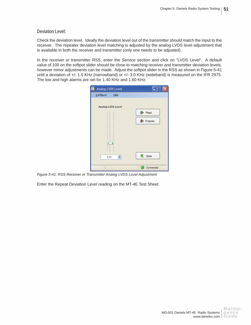
MG-001 Daniels MT-4E Radio Systemswww.danelec.com
Chapter 5: Daniels Radio System Testing 51
Mainte-nance Guide
Deviation Level:
Check the deviation level. Ideally the deviation level out of the transmitter should match the input to the receiver. The repeater deviation level matching is adjusted by the analog LVDS level adjustment that is available in both the receiver and transmitter (only one needs to be adjusted).
In the receiver or transmitter RSS, enter the Service section and click on “LVDS Level”. A default value of 100 on the softpot slider should be close to matching receiver and transmitter deviation levels, however minor adjustments can be made. Adjust the softpot slider in the RSS as shown in Figure 5-41 until a deviation of +/- 1.5 KHz (narrowband) or +/- 3.0 KHz (wideband) is measured on the IFR 2975. The low and high alarms are set for 1.40 KHz and 1.60 KHz.
Figure 5-41: RSS Receiver or Transmitter Analog LVDS Level Adjustment
Enter the Repeat Deviation Level reading on the MT-4E Test Sheet.
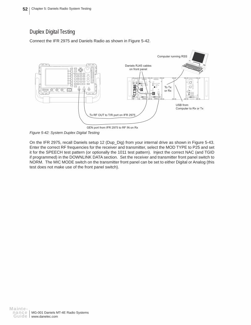
MG-001 Daniels MT-4E Radio Systemswww.danelec.com
Chapter 5: Daniels Radio System Testing52
Mainte-nanceGuide
Duplex Digital TestingConnect the IFR 2975 and Daniels Radio as shown in Figure 5-42.
Figure 5-42: System Duplex Digital Testing
On the IFR 2975, recall Daniels setup 12 (Dup_Dig) from your internal drive as shown in Figure 5-43. Enter the correct RF frequencies for the receiver and transmitter, select the MOD TYPE to P25 and set it for the SPEECH test pattern (or optionally the 1011 test pattern). Inject the correct NAC (and TGID if programmed) in the DOWNLINK DATA section. Set the receiver and transmitter front panel switch to NORM. The MIC MODE switch on the transmitter front panel can be set to either Digital or Analog (this test does not make use of the front panel switch).
REPEATERCONTROL
RX B
TX B
RX A
TX A
CI-RC-4L PULL DOWNTO REMOVE
9
5
3
711
15
9
13
3
711
15
SWITCH A SWITCH B
Computer running RSS
USB fromComputer to Rx or Tx
Tx RF OUT to T/R port on IFR 2975
HELP MODE
TAB
SHIFT
+
-
.
BKSP
HOLD
RETURN
ESC ENTER POWER
1 2ABC
3DEF
JKL MNOGHI654
TUV WXYZPQRS987
#0*
VOLUME
SQUELCH
GEN T/R ANT
125 W MAXMIC AUDIO I/ODVMCH2CH1SCOPETEST PORT
100V MAX 100V MAX 100V MAX
GEN port from IFR 2975 to RF IN on Rx
To Txor Rx
Daniels RJ45 cableson front panel
TRANSMITTER
CNTLBUS
MIC RF OUT
A D
ANALOGDIGITAL
NORMOFFKEY TX
MICMODE
DANIELSELECTRONICS LTD.
REFIN
USB
FREQUENCY (MHz)
MADE IN CANADAMODEL # CODE
RECEIVER
NORM
SQ. DISABLE
OFF
CNTLBUS
A D
RF NI
DANIELSELECTRONICS LTD.
REFIN
USB
FREQUENCY (MHz)
MADE IN CANADAMODEL # CODE
VOL
2
1
5
4
3
678
11
10
9
SYSTEM REGULATORFUNCTION
METER
+
-
12
MADE IN CANADA
DANIELSELECTRONICS LTD.
ONOFF
SPKRINTEXT
EXT
SPKR

MG-001 Daniels MT-4E Radio Systemswww.danelec.com
Chapter 5: Daniels Radio System Testing 53
Mainte-nance Guide
Ensure that the receiver and transmitter are connected to the repeater controller via the RJ45 cables on the front panel. In some systems, the receiver and transmitter may be connected directly together using the RJ45 cables.
Figure 5-43: System Digital Duplex Check

MG-001 Daniels MT-4E Radio Systemswww.danelec.com
Chapter 5: Daniels Radio System Testing54
Mainte-nanceGuide
There are no specifi c measurements to make on this test, just verify that the system is operating correctly.
NAC:
Check to make sure your receiver unsquelches on the proper NAC. If the NAC is set for $F7F in the receiver, ensure that the system transmits the NAC it receives.
TGID:
Check to make sure your receiver unsquelches on the proper TGID code (if used). Ensure that the system transmits the TGID code it receives.
Unit ID (SID):
Ensure that the system transmits the Unit ID code it receives.
*After changing the TGID or Unit ID the SEND button in the DOWNLINK DATA window must be clicked to send the information.
*The TGID and Unit ID programmed into the transmitter via the RSS are only transmitted when keying the transmitter in a non-repeater mode (see the Transmitter Digital Testing). In repeater mode the system transmits the TGID and Unit ID it receives.
Emergency Bit (EMG):
Ensure that the system transmits the Emergency Bit it receives.
Algorithm ID:
The Algorithm ID is typically set for 80 for CLEAR operation.
To ensure encrypted signals will pass through the repeater:
1. Click on the DOWNLINK DATA window to open the full window.
2. Set the ALGID to 81 or select the DES option in the box to the right (this will change the ALGID to 81).
3. Ensure the KEY ID is set to 0000.
4. Click on the UPLINK window to open the full window. In the ES DATA portion of the window the KID will read 0000, the ALGID will read 81, and the MI data will be constantly changing.
5. Check the P25 Digital Repeat Capability Checked box on the MT-4E Test Sheet.

MG-001 Daniels MT-4E Radio Systemswww.danelec.com
Chapter 6: Additional Radio System Tests 55
Mainte-nance Guide
CHAPTER 6: ADDITIONAL RADIO SYSTEM TESTS
A number of additional radio system tests can be performed on the Daniels MT-4E radio system at the radio site with the full radio system. In this chapter, testing of the radio system is typically done as an entire system with the antenna and fi ltering equipment connected.
Filtering equipment is defi ned as duplexers, multicouplers, combiners, or in some cases, an antenna relay.

MG-001 Daniels MT-4E Radio Systemswww.danelec.com
Chapter 6: Additional Radio System Tests56
Mainte-nanceGuide
RADIO SYSTEM TESTING THROUGH FILTERING EQUIPMENT
The Transmitter RF power output and Receiver sensitivity tests can be performed by injecting and measuring the RF signals through the fi ltering equipment. Connect the test set to the antenna port of the fi ltering equipment as shown in Figure 6-1. When testing through this equipment, the test results will be noticeably lower as the fi ltering equipment typically has 1 to 3 dB of insertion loss associated with it.
Figure 6-1: Transmitter and Receiver Testing Through Filtering Equipment
REPEATERCONTROL
RX B
TX B
RX A
TX A
CI-RC-4L PULL DOWNTO REMOVE
9
5
3
711
15
9
13
3
711
15
SWITCH A SWITCH B
Rx Balanced Audio Output(from pins B26 and Z26)
T/R port from IFR 2975 toAntenna port on Duplexer
HELP MODE
TAB
SHIFT
+
-
.
BKSP
HOLD
RETURN
ESC ENTER POWER
1 2ABC
3DEF
JKL MNOGHI654
TUV WXYZPQRS987
#0*
VOLUME
SQUELCH
GEN T/R ANT
125 W MAXMIC AUDIO I/ODVMCH2CH1SCOPETEST PORT
100V MAX 100V MAX 100V MAX
AUDIO IN AUDIO OUT 1 AUDIO OUT 2
Audio InTRANSMITTER
CNTLBUS
MIC RF OUT
A D
ANALOGDIGITAL
NORMOFFKEY TX
MICMODE
DANIELSELECTRONICS LTD.
REFIN
USB
FREQUENCY (MHz)
MADE IN CANADAMODEL # CODE
RECEIVER
NORM
SQ. DISABLE
OFF
CNTLBUS
A D
RF NI
DANIELSELECTRONICS LTD.
REFIN
USB
FREQUENCY (MHz)
MADE IN CANADAMODEL # CODE
RF OUT from Txto Duplexer Duplexer to
RF IN on Rx
VOL
2
1
5
4
3
678
11
10
9
SYSTEM REGULATORFUNCTION
METER
+
-
12
MADE IN CANADA
DANIELSELECTRONICS LTD.
ONOFF
SPKRINTEXT
EXT
SPKR
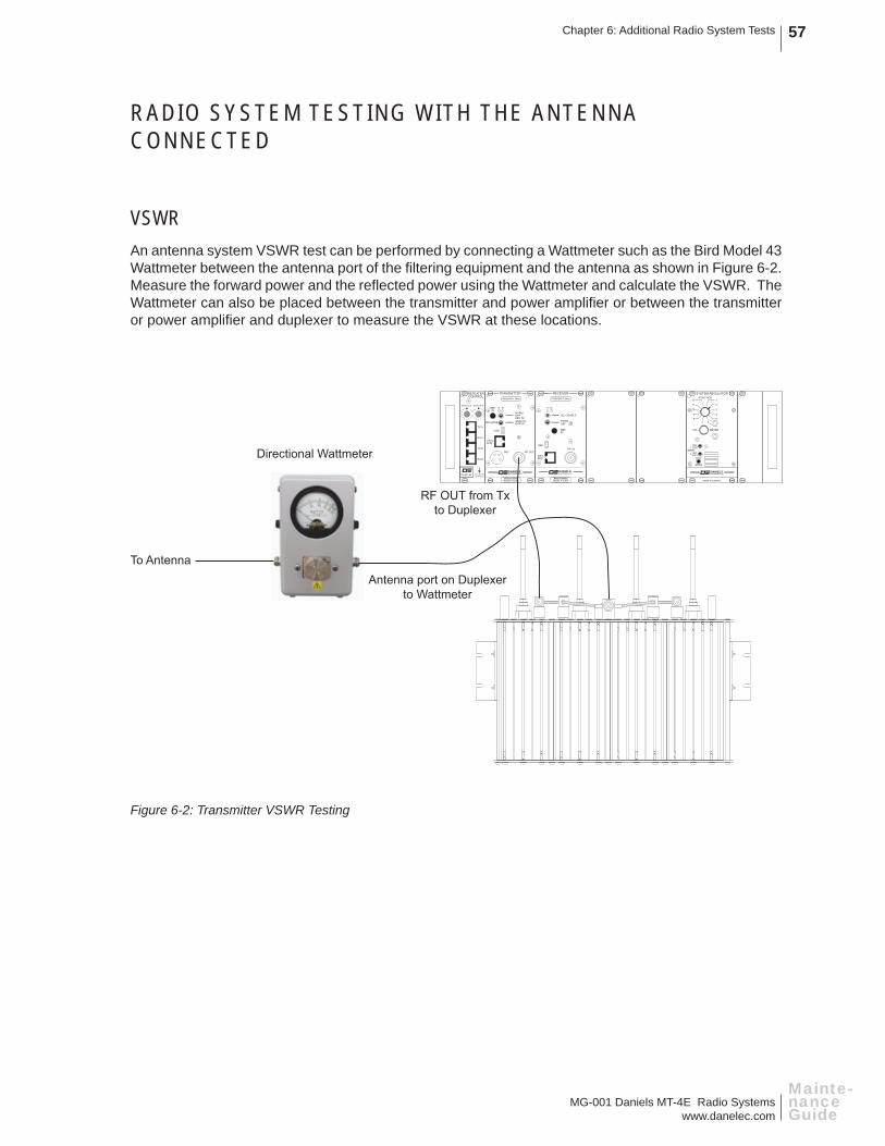
MG-001 Daniels MT-4E Radio Systemswww.danelec.com
Chapter 6: Additional Radio System Tests 57
Mainte-nance Guide
RADIO SYSTEM TESTING WITH THE ANTENNA CONNECTED
VSWRAn antenna system VSWR test can be performed by connecting a Wattmeter such as the Bird Model 43 Wattmeter between the antenna port of the fi ltering equipment and the antenna as shown in Figure 6-2. Measure the forward power and the refl ected power using the Wattmeter and calculate the VSWR. The Wattmeter can also be placed between the transmitter and power amplifi er or between the transmitter or power amplifi er and duplexer to measure the VSWR at these locations.
Figure 6-2: Transmitter VSWR Testing
REPEATERCONTROL
RX B
TX B
RX A
TX A
CI-RC-4L PULL DOWNTO REMOVE
9
5
3
711
15
9
13
3
711
15
SWITCH A SWITCH B
TRANSMITTER
CNTLBUS
MIC RF OUT
A D
ANALOGDIGITAL
NORMOFFKEY TX
MICMODE
DANIELSELECTRONICS LTD.
REFIN
USB
FREQUENCY (MHz)
MADE IN CANADAMODEL # CODE
RECEIVER
NORM
SQ. DISABLE
OFF
CNTLBUS
A D
RF NI
DANIELSELECTRONICS LTD.
REFIN
USB
FREQUENCY (MHz)
MADE IN CANADAMODEL # CODE
Directional Wattmeter
To Antenna
RF OUT from Txto Duplexer
Antenna port on Duplexerto Wattmeter
VOL
2
1
5
4
3
678
11
10
9
SYSTEM REGULATORFUNCTION
METER
+
-
12
MADE IN CANADA
DANIELSELECTRONICS LTD.
ONOFF
SPKRINTEXT
EXT
SPKR
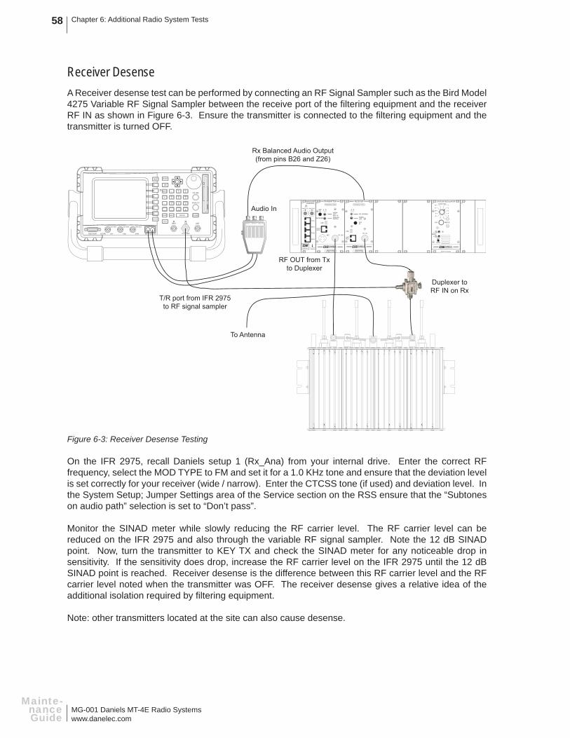
MG-001 Daniels MT-4E Radio Systemswww.danelec.com
Chapter 6: Additional Radio System Tests58
Mainte-nanceGuide
Receiver DesenseA Receiver desense test can be performed by connecting an RF Signal Sampler such as the Bird Model 4275 Variable RF Signal Sampler between the receive port of the fi ltering equipment and the receiver RF IN as shown in Figure 6-3. Ensure the transmitter is connected to the fi ltering equipment and the transmitter is turned OFF.
Figure 6-3: Receiver Desense Testing
On the IFR 2975, recall Daniels setup 1 (Rx_Ana) from your internal drive. Enter the correct RF frequency, select the MOD TYPE to FM and set it for a 1.0 KHz tone and ensure that the deviation level is set correctly for your receiver (wide / narrow). Enter the CTCSS tone (if used) and deviation level. In the System Setup; Jumper Settings area of the Service section on the RSS ensure that the “Subtones on audio path” selection is set to “Don’t pass”.
Monitor the SINAD meter while slowly reducing the RF carrier level. The RF carrier level can be reduced on the IFR 2975 and also through the variable RF signal sampler. Note the 12 dB SINAD point. Now, turn the transmitter to KEY TX and check the SINAD meter for any noticeable drop in sensitivity. If the sensitivity does drop, increase the RF carrier level on the IFR 2975 until the 12 dB SINAD point is reached. Receiver desense is the difference between this RF carrier level and the RF carrier level noted when the transmitter was OFF. The receiver desense gives a relative idea of the additional isolation required by fi ltering equipment.
Note: other transmitters located at the site can also cause desense.
REPEATERCONTROL
RX B
TX B
RX A
TX A
CI-RC-4L PULL DOWNTO REMOVE
9
5
3
711
15
9
13
3
711
15
SWITCH A SWITCH B
Rx Balanced Audio Output(from pins B26 and Z26)
T/R port from IFR 2975to RF signal sampler
HELP MODE
TAB
SHIFT
+
-
.
BKSP
HOLD
RETURN
ESC ENTER POWER
1 2ABC
3DEF
JKL MNOGHI654
TUV WXYZPQRS987
#0*
VOLUME
SQUELCH
GEN T/R ANT
125 W MAXMIC AUDIO I/ODVMCH2CH1SCOPETEST PORT
100V MAX 100V MAX 100V MAX
AUDIO IN AUDIO OUT 1 AUDIO OUT 2
Audio InTRANSMITTER
CNTLBUS
MIC RF OUT
A D
ANALOGDIGITAL
NORMOFFKEY TX
MICMODE
DANIELSELECTRONICS LTD.
REFIN
USB
FREQUENCY (MHz)
MADE IN CANADAMODEL # CODE
RECEIVER
NORM
SQ. DISABLE
OFF
CNTLBUS
A D
RF NI
DANIELSELECTRONICS LTD.
REFIN
USB
FREQUENCY (MHz)
MADE IN CANADAMODEL # CODE
RF OUT from Txto Duplexer
Duplexer toRF IN on Rx
To Antenna
VOL
2
1
5
4
3
678
11
10
9
SYSTEM REGULATORFUNCTION
METER
+
-
12
MADE IN CANADA
DANIELSELECTRONICS LTD.
ONOFF
SPKRINTEXT
EXT
SPKR
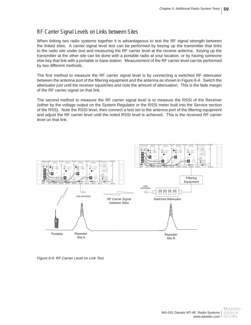
MG-001 Daniels MT-4E Radio Systemswww.danelec.com
Chapter 6: Additional Radio System Tests 59
Mainte-nance Guide
RF Carrier Signal Levels on Links between SitesWhen linking two radio systems together it is advantageous to test the RF signal strength between the linked sites. A carrier signal level test can be performed by keying up the transmitter that links to the radio site under test and measuring the RF carrier level at the receive antenna. Keying up the transmitter at the other site can be done with a portable radio at your location, or by having someone else key that link with a portable or base station. Measurement of the RF carrier level can be performed by two different methods.
The fi rst method to measure the RF carrier signal level is by connecting a switched RF attenuator between the antenna port of the fi ltering equipment and the antenna as shown in Figure 6-4. Switch the attenuator just until the receiver squelches and note the amount of attenuation. This is the fade margin of the RF carrier signal on that link.
The second method to measure the RF carrier signal level is to measure the RSSI of the Receiver (either by the voltage output on the System Regulator or the RSSI meter built into the Service section of the RSS). Note the RSSI level, then connect a test set to the antenna port of the fi ltering equipment and adjust the RF carrier level until the noted RSSI level is achieved. This is the received RF carrier level on that link.
Figure 6-4: RF Carrier Level on Link Test
Portable RepeaterSite B
RepeaterSite A
LINK ANTENNA
REPEATERCONTROL
RX B
TX B
RX A
TX A
CI-RC-4L PULL DOWNTO REMOVE
9
5
3
711
15
9
13
3
711
15
SWITCH A SWITCH B
TRANSMITTER
CNTLBUS
MIC RF OUT
A D
ANALOGDIGITAL
NORMOFFKEY TX
MICMODE
DANIELSELECTRONICS LTD.
REFIN
USB
FREQUENCY (MHz)
MADE IN CANADAMODEL # CODE
RECEIVER
NORM
SQ. DISABLE
OFF
CNTLBUS
A D
RF NI
DANIELSELECTRONICS LTD.
REFIN
USB
FREQUENCY (MHz)
MADE IN CANADAMODEL # CODE
TRANSMITTER
CNTLBUS
MIC RF OUT
A D
ANALOGDIGITAL
NORMOFFKEY TX
MICMODE
DANIELSELECTRONICS LTD.
REFIN
USB
FREQUENCY (MHz)
MADE IN CANADAMODEL # CODE
RECEIVER
NORM
SQ. DISABLE
OFF
CNTLBUS
A D
RF NI
DANIELSELECTRONICS LTD.
REFIN
USB
FREQUENCY (MHz)
MADE IN CANADAMODEL # CODE
Switched AttenuatorRF Carrier Signalbetween Sites
LINKANTENNA
FilteringEquipment
VOL
2
1
5
4
3
678
11
10
9
SYSTEM REGULATORFUNCTION
METER
+
-
12
MADE IN CANADA
DANIELSELECTRONICS LTD.
ONOFF
SPKRINTEXT
EXT
SPKR
VOL
2
1
5
4
3
678
11
10
9
SYSTEM REGULATORFUNCTION
METER
+
-
12
MADE IN CANADA
DANIELSELECTRONICS LTD.
ONOFF
SPKRINTEXT
EXT
SPKR

MG-001 Daniels MT-4E Radio Systemswww.danelec.com
Chapter 6: Additional Radio System Tests60
Mainte-nanceGuide
Spurious Signals over the AirA spurious signal test can be performed by keying up the transmitter over the air and observing the spectrum using a Spectrum Analyzer with an antenna on the input port as shown in Figure 6-5.
On the Spectrum Analyzer, attenuate the incoming RF signal so that the RF carrier does not extend beyond the range of the display on the Spectrum Analyzer (this will overdrive the receiver of the analyzer causing erroneous spurs to be shown in the spectrum).
Look at the spectrum and ensure there are no large spurs being generated by the radio system.
Figure 6-5: Spurious Signals over the Air Test
REPEATERCONTROL
RX B
TX B
RX A
TX A
CI-RC-4L PULL DOWNTO REMOVE
9
5
3
711
15
9
13
3
711
15
SWITCH A SWITCH B
TRANSMITTER
CNTLBUS
MIC RF OUT
A D
ANALOGDIGITAL
NORMOFFKEY TX
MICMODE
DANIELSELECTRONICS LTD.
REFIN
USB
FREQUENCY (MHz)
MADE IN CANADAMODEL # CODE
RECEIVER
NORM
SQ. DISABLE
OFF
CNTLBUS
A D
RF NI
DANIELSELECTRONICS LTD.
REFIN
USB
FREQUENCY (MHz)
MADE IN CANADAMODEL # CODE
Radio System Transmitting Over the Air
Spectrum Analyzer
VOL
2
1
5
4
3
678
11
10
9
SYSTEM REGULATORFUNCTION
METER
+
-
12
MADE IN CANADA
DANIELSELECTRONICS LTD.
ONOFF
SPKRINTEXT
EXT
SPKR

MG-001 Daniels MT-4E Radio Systemswww.danelec.com
Chapter 7: Blank Worksheets 61
Mainte-nance Guide
CHAPTER 7: BLANK WORKSHEETS
Rad
io S
ite C
heck
list
Dat
e (D
/M/Y
)Te
chni
cian
Rad
io S
ite N
ame
Prep
arat
ion
for a
Site
Sur
vey
Com
mun
icat
ions
Ser
vice
Mon
itor
Pap
er a
nd p
enci
lsM
ultim
eter
Sol
derin
g iro
nS
pare
radi
o eq
uipm
ent
Por
tabl
e R
adio
Sta
ndar
d to
ol b
oxS
urvi
val G
ear,
Food
and
Drin
kE
xtra
RF
cabl
ing
Cam
era
Ada
pter
sK
eys
Ext
ende
r car
dsS
yste
m /
Site
Doc
umen
tatio
nA
-TK
-04
Tool
Kit
Wild
life
dete
rren
t
Exte
rior S
ite S
urve
yB
uild
ing
Con
ditio
nS
ite P
hoto
grap
hsA
nten
nas
and
stru
ctur
eR
F ca
bles
and
con
nect
ors
Leas
ed li
nes
and
pow
er c
able
sLi
ghtn
ing
prot
ectio
nO
bstru
ctio
ns
Inte
rior S
ite S
urve
yB
uild
ing
Con
ditio
nS
ite P
hoto
grap
hsC
abin
et /
Equ
ipm
ent R
ack
RF
cabl
es a
nd c
onne
ctor
sD
uple
xers
/ C
ombi
ners
/ M
utlic
oupl
ers
Leas
ed li
nes
and
pow
er c
able
sP
ower
sup
ply
/ bat
terie
s / s
olar
pan
els
Rad
io S
yste
m T
estin
gR
adio
Site
Inve
ntor
yR
adio
sys
tem
test
edIn
vent
ory
com
plet
ed
Dep
artu
reR
F ca
bles
/ fil
terin
g / a
nten
nas
Pow
er s
uppl
y co
nnec
ted
and
oper
atio
nal
Sw
itche
s in
cor
rect
pos
ition
RJ4
5 In
terc
onne
ct c
able
plu
gged
inLi
ghts
off
/ Tow
er li
ghts
on
Rad
io s
yste
m c
heck
per
form
edD
oor i
s cl
osed
and
lock
ed
DA
NIE
LSE
LEC
TRO
NIC
S L
TD.TM

MG-001 Daniels MT-4E Radio Systemswww.danelec.com
Chapter 7: Blank Worksheets62
Mainte-nanceGuide
Radio Site Inventory
Date (D
/M/Y
)Technician
Radio S
ite Nam
e
Description
Model N
umber
Serial N
umber
Daniels R
adio SystemS
ubrackS
ystem R
egulatorC
ontrol Card
Receiver A
Transmitter A
Receiver B
Transmitter B
30 Watt P
ower A
mplifier
Pow
er Converter
Additional Equipm
entD
uplexerD
uplexerC
ombiner
Mulitcoupler
Pow
er Supply
Cabinet / R
ackA
ntennaA
ntenna
VH
F ___ UH
F ___ Links to: ____________________V
HF ___ U
HF ___ Links to: ____________________
VH
F ___ UH
F ___V
HF ___ U
HF ___
Additional Inform
ation
96 pin Auxiliary C
onnector on back ___O
ne Antenna R
elay ___ Two A
ntenna Relays ___
CI-R
C-4L ___ C
I-BC
-4E ___ C
I-RC
-4M ___
VH
F ___ UH
F ___ Links to: ____________________V
HF ___ U
HF ___ Links to: ____________________
VH
F ___ UH
F ___ Links to: ____________________
VH
F ___ UH
F ___
AC
-DC
___ DC
-DC
___
VH
F ___ UH
F ___
DA
NIE
LSE
LEC
TRO
NIC
S LTD
. TM

MG-001 Daniels MT-4E Radio Systemswww.danelec.com
Chapter 7: Blank Worksheets 63
Mainte-nance Guide
MT-
4E R
adio
Sys
tem
Tes
t She
et
Dat
e (D
/M/Y
)Fi
rmw
are
Ver
sion
sS
eria
l Num
bers
Rx:
____
____
____
_R
ecei
ver:_
____
____
____
____
___
Tx:_
____
____
____
Tran
smitt
er:_
____
____
____
____
_
Mea
sure
men
tSy
stem
Mon
itor T
estin
gV
dcV
dcV
dc
Rec
eive
r Tes
ting
%dB
mS
quel
chdB
mU
nsqu
elch
dBm
dBm
Ref
eren
ce S
ensi
tivity
(5%
BE
R)
dBm Hz
Tran
smitt
er T
estin
g% W W
KH
zM
axim
um D
evia
tion
(1.3
KH
z to
ne @
+10
dB
m)
KH
zH
z % Hz
Syst
em T
estin
gm
A AdB
mK
Hz
KH
z %
* Th
e P
aram
eter
s as
sho
wn
are
for r
oom
tem
pera
ture
(25
°C) t
estin
g. R
esul
ts o
ver t
he e
ntire
tem
pera
ture
rang
e (-
30C
to +
60C
) may
var
y.
Aux
iliar
y D
evia
tion
Leve
l (0
dBm
aux
iliar
y in
put)
± 1.
5 K
Hz
(12.
5 K
Hz)
or ±
3.0
KH
z (2
5 K
Hz)
± 0
.1 K
Hz
2.5
KH
z (1
2.5
KH
z) o
r 5
.0 K
Hz
(25
KH
z)
P25
Dig
ital R
epea
t Cap
abili
ty C
heck
edC
heck
mar
k
Rep
eat D
evia
tion
Leve
l±
1.5
KH
z (1
2.5
KH
z) o
r ± 3
.0 K
Hz
(25
KH
z) ±
0.1
KH
zS
yste
m D
isto
rtion
No
para
met
er (t
ypic
ally
4
.0%
)
Aux
iliar
y A
udio
Out
put L
evel
Bal
ance
d A
udio
Out
put L
evel
L.O
. Ref
eren
ce O
scill
ator
Offs
et
-8.0
dB
m (3
08 m
Vrm
s @
600
ohm
s) ±
0.5
dB
m -1
18 d
Bm
(VH
F an
d U
HF)
/ -1
16 d
Bm
(800
MH
z)±
1.0
ppm
(VH
F) /
± 0.
5 pp
m (U
HF)
/ ±
0.1
ppm
(800
MH
z)
Aud
io D
isto
rtion
Ref
eren
ce S
ensi
tivity
(12
dB S
INA
D)
Squ
elch
Thr
esho
lds
Des
crip
tion
Sup
ply
Vol
tage
+9.5
Vol
ts R
egul
ated
Rec
eive
r RS
SI @
-100
dB
m
Par
amet
ers
+10
Vdc
to +
17 V
dc (+
13.8
Vdc
nom
inal
)+9
.5 V
dc (±
0.1
Vdc
)0
Vdc
to +
3.3
Vdc
2.0
% 1
KH
z To
ne @
60%
max
imum
dev
iatio
n -1
18 d
Bm
(VH
F an
d U
HF)
/ -1
16 d
Bm
(800
MH
z)N
o pa
ram
eter
(typ
ical
ly s
quel
ch /
unsq
uelc
h po
ints
are
cen
tere
dar
ound
12
dB S
INA
D p
oint
with
6 d
B o
f hys
tere
sis)
3.0
% 1
KH
z To
ne @
60%
max
imum
dev
iatio
n
CTC
SS
Enc
ode
Tone
Dev
iatio
n±
350
Hz
(12.
5 K
Hz)
or ±
500
Hz
(25
KH
z) ±
50
Hz
C4F
M M
odul
atio
n Fi
delit
y 5
.0%
Dev
iatio
n Le
vel (
-8.0
dB
m a
udio
inpu
t)±
1.5
KH
z (1
2.5
KH
z) o
r ± 3
.0 K
Hz
(25
KH
z) ±
0.1
KH
z
Tran
smitt
er R
F P
ower
Out
put
0.5
to 8
.0 W
Con
tinuo
us (V
HF
and
UH
F) /
0.5
to 3
.0 W
(800
MH
z)A
udio
Dis
torti
on
0 dB
m (7
75 m
Vrm
s @
600
ohm
s) ±
0.5
dB
m
Am
plifi
er R
F P
ower
Out
put
No
para
met
er (s
yste
m d
epen
dent
)
Car
rier R
efer
ence
Osc
illat
or O
ffset
± 1.
0 pp
m (V
HF)
/ ±
0.5
ppm
(UH
F) /
± 0.
1 pp
m (8
00 M
Hz)
No
para
met
er (s
yste
m d
epen
dent
)S
tand
by C
urre
nt D
raw
Tran
smit
Cur
rent
Dra
wN
o pa
ram
eter
(sys
tem
dep
ende
nt)
DA
NIE
LSE
LEC
TRO
NIC
S L
TD.TM

MG-001 Daniels MT-4E Radio Systemswww.danelec.com
64
Mainte-nanceGuide
This Page Intentionally Left Blank


Daniels Electronics Ltd.43 Erie Street, Victoria, BCCanada, V8V [email protected]
Toll Free Canada and USAPhone: 1-800-664-4066Fax: 1-877-750-0004
InternationalPhone: 250-382-8268Fax: 250-382-6139
©2009 Daniels Electronics Ltd. All Rights Reserved.
MG-001-4-0-0
www.danelec.com


