Data Sheet DS/NDL-EN Rev. B
PROFIBUS Links & Coupler
Pos: 2 /Grid-Layout/Titelseiten/Datenblatt/Feldbus + Tools/NDL - PROFIBUS @ 98\mod_1483611433725_3101.docx @ 932438 @ @ 4
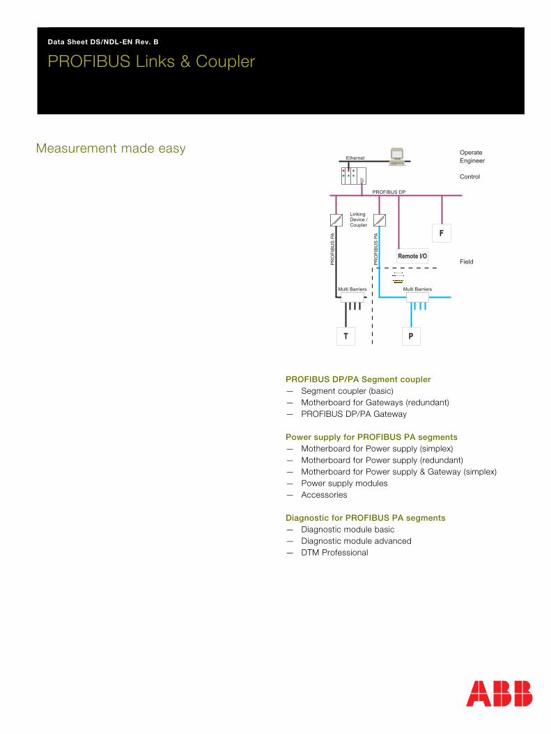
Measurement made easy
PROFIBUS DP/PA Segment coupler — Segment coupler (basic) — Motherboard for Gateways (redundant) — PROFIBUS DP/PA Gateway Power supply for PROFIBUS PA segments — Motherboard for Power supply (simplex) — Motherboard for Power supply (redundant) — Motherboard for Power supply & Gateway (simplex) — Power supply modules — Accessories Diagnostic for PROFIBUS PA segments — Diagnostic module basic — Diagnostic module advanced — DTM Professional
=== Ende der Liste für Textmarke Cover ===
Pos: 4 /Grid-Layout/++++++++++++ Seitenumbruch ++++++++++++ @ 27\mod_1238577222488_0.docx @ 254391 @ @ 1

PROFIBUS Links & Coupler
2 DS/NDL-EN Rev. B | PROFIBUS Links & Coupler
Pos: 5 /Grid-Layout/++++++++++++ Wechsel von ein- auf zweispaltig ++++++++++++ @ 27\mod_1238577723694_0.docx @ 254499 @ @ 1 Change from one to two columns Pos: 6.1 /Grid-Layout/Technische Daten/Geräte-Management und Feldbus/NDL - PROFIBUS/NDL/Compact/Einleitung/Überschrift NDL300 basic @ 98\mod_1483613151149_3101.docx @ 932494 @ 1 @ 1
NDL300 – Segment coupler (basic) Pos: 6.2 /Grid-Layout/Technische Daten/Geräte-Management und Feldbus/NDL - PROFIBUS/NDL/Compact/Einleitung/Einleitung @ 98\mod_1483611890775_3101.docx @ 932466 @ @ 1
— Output: 24 ... 26 V/400 mA — Couples PROFIBUS PA devices transparently to
PROFIBUS DP — High-power trunk for high device count and long cable
lengths — Installation in Zone 2/Class I, Div. 2 — Up to 1.5 MBit auto-adapting — PROFIBUS DP terminator selectable — Power Rail support Pos: 6.3 /Grid-Layout/Technische Daten/Geräte-Management und Feldbus/NDL - PROFIBUS/NDL/Compact/Einleitung/Abbildung Allgemeine Beschreibung @ 49\mod_1310638030530_3101.docx @ 407675 @ @ 1
Pos: 6.4 /Grid-Layout/++++++++++++ Wechsel von zwei- auf einspaltig ++++++++++++ @ 27\mod_1238577808304_0.docx @ 254523 @ @ 1
Change from two to one column Pos: 6.5 /Grid-Layout/++++++++++++ Wechsel von ein- auf zweispaltig ++++++++++++ @ 27\mod_1238577723694_0.docx @ 254499 @ @ 1 Change from one to two columns Pos: 6.6 /Grid-Layout/Technische Daten/Geräte-Management und Feldbus/NDL - PROFIBUS/NDL/Compact/Einleitung/Allgemeine Beschreibung @ 98\mod_1483614216094_3101.docx @ 932523 @ @ 1
The basic Segment Coupler is an all-in-one gateway and fieldbus power supply for connecting PROFIBUS PA to PROFIBUS DP transparently. The power output suits long cable lengths and high device counts. Device couplers provide explosion protection for live work at the spur where needed. Communication is transparent between DP and PA. The gateway of the Segment Coupler makes each PA device appear as if it was connected to DP: This relates to addressing, cyclic/acyclic data exchange, and the transfer rate.
Segment design is clear and easy to understand without subnetworks. The gateway itself is confguration-free. All in all, these features significantly reduce engineering work. Availability and a long service life are achieved through a passive impedance filter and a design optimized for low heat dissipation. Pos: 6.7 /Grid-Layout/++++++++++++ Wechsel von zwei- auf einspaltig ++++++++++++ @ 27\mod_1238577808304_0.docx @ 254523 @ @ 1
Change from two to one column Pos: 6.8 /Grid-Layout/Technische Daten/Geräte-Management und Feldbus/NDL - PROFIBUS/NDL/Compact/Einleitung/Abbildung Allgemeine Beschreibung II @ 79\mod_1418033793579_3101.docx @ 667727 @ @ 1
Pos: 6.9 /Grid-Layout/++++++++++++ Wechsel von ein- auf zweispaltig ++++++++++++ @ 27\mod_1238577723694_0.docx @ 254499 @ @ 1 Change from one to two columns Pos: 6.10 /Grid-Layout/++++++++++++ Seitenumbruch ++++++++++++ @ 27\mod_1238577222488_0.docx @ 254391 @ @ 1

PROFIBUS Links & Coupler | DS/NDL-EN Rev. B 3
Pos: 6.11 /Grid-Layout/Technische Daten/Geräte-Management und Feldbus/NDL - PROFIBUS/NDL/Compact/Einleitung/Überschrift NDL300 basic @ 98\mod_1483613151149_3101.docx @ 932494 @ 1 @ 1
NDL300 – Segment coupler (basic) Pos: 6.12 /Grid-Layout/Überschriften/1.1/S - U/Technische Daten @ 49\mod_1311076392227_3101.docx @ 408982 @ @ 1
Specifications Pos: 6.13 /Grid-Layout/Technische Daten/Geräte-Management und Feldbus/NDL - PROFIBUS/NDL/Compact/Technische Daten/Technische Daten @ 79\mod_1417439683299_3101.docx @ 664804 @ @ 1
General specifications
Design / Mounting Cabinet installation
Supply
Connection Power Rail or terminals 11 (L+), 12 (L-)
Rated voltage Un 20 ... 30 V DC
Ripple ≤ 10 %
Rated current In 640 ... 365 mA
Power dissipation max 2.5 W
Fieldbus interface
PROFIBUS PA
Connection 3+, 6+, 2-, 5-, 1 shield, 4 shield
Rated voltage 24 ... 26 V
Rated current ≤ 400 mA
Terminating
impedance 100 Ω , integrated
PROFIBUS DP PROFIBUS with RS-485 transmission
technology
Connection Terminals 7 RxD/TxD-P, 8 RxD/TxD-N, 9
shield, 10 FE
Baud rate 1.5 MBit/s max.
Indicators / operating means
Switch PROFIBUS DP terminator
LED PWR Green: Power on
LED DP/ERR Red 2 Hz flashing: DP error red on:
Hardware error red off:
DP communication detected
LED PA Red 2 Hz flashing: No PA communication or
overload Off: PA communication OK
Electrical isolation
PROFIBUS DP /
PROFIBUS PA
Functional insulation acc. to IEC 62103,
rated insulation voltage 50 V AC / 70 V DC
PROFIBUS DP / Supply Basic insulation according to IEC/EN
61010, rated insulation voltage 253 V AC /
357 V DC
PROFIBUS PA / Supply Basic insulation according to IEC/EN
61010, rated insulation voltage 253 V AC /
357 V DC
Directive conformity
Electromagnetic compatibility
Directive 2014/30/EU EN 61326-1:2013
Standard conformity
Electromagnetic compatibility NAMUR NE 21
Degree of protection IEC/EN 60529
Fieldbus standard EN 50170/2
Climatic conditions DIN IEC 721
Shock resistance EN 60068-2-27
Vibration resistance EN 60068-2-6
Ambient conditions
Ambient temperature -40 ... 60 °C (-40 ... 140 °F)
Storage temperature -40 ... 85 °C (-40 ... 185 °F)
Relative humidity < 95 % non-condensing
Shock resistance 15 g 11 ms
Vibration resistance 1 g 10 ... 150 Hz
Pollution degree Max. 2, according to IEC 60664
Corrosion resistance Acc. to ISA-S71.04-1985, severity
level G3
Mechanical specifications
Connection type Terminals
Core cross-section Up to 2.5 mm2
Housing material Polycarbonate
Degree of protection IP 20
Mass 180 g
Mounting DIN rail mounting
Data for application in connection with Ex-areas
Statement of conformity TÜV 16 ATEX 7831 X
Group, category, type of
protection, temperature
class
II 3G Ex ec IIC T4 Gc
Directive conformity
Directive 2014/34/EU EN 60079-0:2012 , EN 60079-
7:2015
International approvals
CSA approval CSA 16.70064204
Approved for Class I, Division 2, Groups A, B, C, D
Class I, Zone 2, Ex nA IIC T4 Gc
IECEx approval IECEx TUR 16.0006X
Approved for Ex ec IIC T4 Gc
Pos: 6.14 /Grid-Layout/++++++++++++ Seitenumbruch ++++++++++++ @ 27\mod_1238577222488_0.docx @ 254391 @ @ 1
PROFIBUS Links & Coupler
4 DS/NDL-EN Rev. B | PROFIBUS Links & Coupler
Pos: 6.15 /Grid-Layout/Technische Daten/Geräte-Management und Feldbus/NDL - PROFIBUS/NDL/Compact/Einleitung/Überschrift NDL300 basic @ 98\mod_1483613151149_3101.docx @ 932494 @ 1 @ 1
NDL300 – Segment coupler (basic) Pos: 6.16 /Grid-Layout/Technische Daten/Geräte-Management und Feldbus/NDL - PROFIBUS/NDL/Compact/Technische Daten/Technische Daten 2 @ 98\mod_1483617981206_3101.docx @ 932551 @ @ 4
General information
Supplementary information Statement of Conformity, Declaration
of Conformity, Attestation of
Conformity and instructions have to
be observed where applicable.
Pos: 6.17 /Grid-Layout/++++++++++++ Spaltenumbruch ++++++++++++ @ 27\mod_1238577564630_0.docx @ 254475 @ @ 1
Pos: 6.18 /Grid-Layout/++++++++++++ Wechsel von zwei- auf einspaltig ++++++++++++ @ 27\mod_1238577808304_0.docx @ 254523 @ @ 1
Change from two to one column Pos: 6.19 /Grid-Layout/++++++++++++ Absatzmarke (einzeln) ++++++++++++ @ 56\mod_1329208232428_0.docx @ 484352 @ @ 1
Pos: 6.20 /Grid-Layout/Technische Daten/Geräte-Management und Feldbus/NDL - PROFIBUS/NDL/Compact/Technische Daten/System Component Overview @ 98\mod_1483618801328_3101.docx @ 932699 @ @ 1
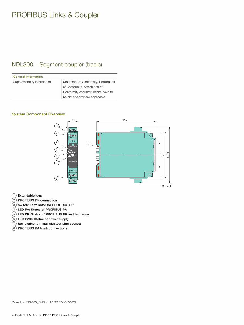
System Component Overview
1 Extendable lugs
2 PROFIBUS DP connection
3 Switch: Terminator for PROFIBUS DP
4 LED PA: Status of PROFIBUS PA
5 LED DP: Status of PROFIBUS DP and hardware
6 LED PWR: Status of power supply
7 Removable terminal with test plug sockets
8 PROFIBUS PA trunk connections
Pos: 6.21 /Grid-Layout/Technische Daten/Geräte-Management und Feldbus/NDL - PROFIBUS/NDL/Compact/Fußzeile "Based on" @ 98\mod_1483620769375_3101.docx @ 932792 @ @ 1
Based on 277830_ENG.xml / RD 2016-06-23 Pos: 7 /Grid-Layout/++++++++++++ Seitenumbruch ++++++++++++ @ 27\mod_1238577222488_0.docx @ 254391 @ @ 1

PROFIBUS Links & Coupler | DS/NDL-EN Rev. B 5
Pos: 8 /Grid-Layout/++++++++++++ Wechsel von ein- auf zweispaltig ++++++++++++ @ 27\mod_1238577723694_0.docx @ 254499 @ @ 1 Change from one to two columns Pos: 9.1 /Grid-Layout/Technische Daten/Geräte-Management und Feldbus/NDL - PROFIBUS/NDL/Redundant/Einleitung/Überschrift NDL300 redundant @ 49\mod_1311078942689_3101.docx @ 409010 @ 1 @ 1
NDL300 – Motherboard for Gateways (redundant) Pos: 9.2 /Grid-Layout/Technische Daten/Geräte-Management und Feldbus/NDL - PROFIBUS/NDL/Redundant/Einleitung/Einleitung @ 98\mod_1483621744924_3101.docx @ 932820 @ @ 1
— For 2 gateway modules —For PROFIBUS PA —Redundant configuration —Installation in Zone 2/Class I, Div. 2 Pos: 9.3 /Grid-Layout/Technische Daten/Geräte-Management und Feldbus/NDL - PROFIBUS/NDL/Redundant/Einleitung/Abbildung Allgemeine Beschreibung @ 49\mod_1311079661066_3101.docx @ 409082 @ @ 1
Pos: 9.4 /Grid-Layout/++++++++++++ Wechsel von zwei- auf einspaltig ++++++++++++ @ 27\mod_1238577808304_0.docx @ 254523 @ @ 1
Change from two to one column Pos: 9.5 /Grid-Layout/++++++++++++ Wechsel von ein- auf zweispaltig ++++++++++++ @ 27\mod_1238577723694_0.docx @ 254499 @ @ 1 Change from one to two columns Pos: 9.6 /Grid-Layout/Technische Daten/Geräte-Management und Feldbus/NDL - PROFIBUS/NDL/Redundant/Einleitung/Allgemeine Beschreibung @ 98\mod_1483622057680_3101.docx @ 932848 @ @ 1
This motherboard is a system component of the Power Hub. It is the mounting base and wiring interface for 2 communication gateways. In connection with power supply modules and the respective motherboard it forms a complete unit for power supply of segments with data conversion. Sockets for all modules enable simple installation and replacement without tools.
The motherboard supports a choice of gateways for different host protocols. A PROFIBUS PA master for each segment enables short bus cycle times. The DCS can access the advanced diagnostic module directly via the gateway without additional wiring or configuration. Pos: 9.7 /Grid-Layout/++++++++++++ Wechsel von zwei- auf einspaltig ++++++++++++ @ 27\mod_1238577808304_0.docx @ 254523 @ @ 1
Change from two to one column Pos: 9.8 /Grid-Layout/Technische Daten/Geräte-Management und Feldbus/NDL - PROFIBUS/NDL/Redundant/Einleitung/Abbildung Allgemeine Beschreibung II @ 79\mod_1418218734561_3101.docx @ 668439 @ @ 1
Pos: 9.9 /Grid-Layout/++++++++++++ Wechsel von ein- auf zweispaltig ++++++++++++ @ 27\mod_1238577723694_0.docx @ 254499 @ @ 1 Change from one to two columns Pos: 9.10 /Grid-Layout/++++++++++++ Seitenumbruch ++++++++++++ @ 27\mod_1238577222488_0.docx @ 254391 @ @ 1
PROFIBUS Links & Coupler
6 DS/NDL-EN Rev. B | PROFIBUS Links & Coupler
Pos: 9.11 /Grid-Layout/Technische Daten/Geräte-Management und Feldbus/NDL - PROFIBUS/NDL/Redundant/Einleitung/Überschrift NDL300 redundant @ 49\mod_1311078942689_3101.docx @ 409010 @ 1 @ 1
NDL300 – Motherboard for Gateways (redundant) Pos: 9.12 /Grid-Layout/Überschriften/1.1/S - U/Technische Daten @ 49\mod_1311076392227_3101.docx @ 408982 @ @ 1
Specifications Pos: 9.13 /Grid-Layout/Technische Daten/Geräte-Management und Feldbus/NDL - PROFIBUS/NDL/Redundant/Technische Daten/Technische Daten @ 98\mod_1483622337127_3101.docx @ 932876 @ @ 4
General specifications
Design / Mounting Motherboard based
Supply
Rated voltage Un 19.2 ... 35 V SELV/PELV
Rated current In 2 ... 3 A
Indicators/operating means
Fault signal VFC alarm output via connectors
Rotary switch Bus addressing, gateway-specific
Directive conformity
Electromagnetic compatibility
Directive 2014/30/EU EN 61326-1:2013
Standard conformity
Electromagnetic compatibility NE 21:2011
Degree of protection IEC 60529
Fieldbus standard IEC 61158-2
Shock resistance EN 60068-2-27
Vibration resistance EN 60068-2-6
Ambient conditions
Ambient temperature -40 ... 70 °C (-40 ... 158 °F)
Storage temperature -40 ... 85 °C (-40 ... 185 °F)
Relative humidity < 95 % non-condensing
Shock resistance 15 g 11 ms
Vibration resistance 1 g , 10 ... 150 Hz
Pollution Degree Max. 2, according to IEC 60664
Corrosion resistance Acc. to ISA-S71.04-1985, severity
level G3
Mechanical specifications
Housing material Polycarbonate
Degree of protection IP 20
Mass approx. 300 g
Mounting DIN mounting rail
Data for application in connection with Ex-areas
Statement of conformity TÜV 15 ATEX 7735 X
Group, category, type of
protection, temperature
classification
II 3 G Ex ec IIC T4 Gc
Directive conformity
Directive 2014/34/EU EN 60079-0:2012 , EN 60079-
7:2015 , EN 60079-11:2012
International approvals
IECEx approval IECEx TUR 16.0007X
Approved for Ex ec IIC T4 Gc
Certificates and approvals
Marine approval Pending
Supplementary information Statement of Conformity, Declaration of Conformity, Attestation of Conformity and instructions have to be observed where applicable. Pos: 9.14 /Grid-Layout/++++++++++++ Seitenumbruch ++++++++++++ @ 27\mod_1238577222488_0.docx @ 254391 @ @ 1

PROFIBUS Links & Coupler | DS/NDL-EN Rev. B 7
Pos: 9.15 /Grid-Layout/++++++++++++ Wechsel von zwei- auf einspaltig ++++++++++++ @ 27\mod_1238577808304_0.docx @ 254523 @ @ 1 Change from two to one column Pos: 9.16 /Grid-Layout/Technische Daten/Geräte-Management und Feldbus/NDL - PROFIBUS/NDL/Redundant/Einleitung/Überschrift NDL300 redundant @ 49\mod_1311078942689_3101.docx @ 409010 @ 1 @ 1
NDL300 – Motherboard for Gateways (redundant) Pos: 9.17 /Grid-Layout/Überschriften/1.1/M - O/Montageabmessungen @ 48\mod_1307436478312_3101.docx @ 403487 @ @ 1
Mounting dimensions Pos: 9.18 /Grid-Layout/Technische Daten/Geräte-Management und Feldbus/NDL - PROFIBUS/NDL/Redundant/Montageabmessungen/Montageabmessungen @ 98\mod_1483946176893_3101.docx @ 932948 @ @ 4
1 Motherboard
b Gateway, see separate datasheet
c Connections: Volt-free contact alarm and diagnostic bus. Diagnostic link cable, optional accessory
d SUB-D interface for the connection of Power Hub motherboards
e Rotary switches for gateway addressing, x1, x10, x100
f Earth connection
g Mounting slot for DIN mounting rai
Link cable between gateway motherboard and Power Hub motherboard. 1 cable comes with the gateway motherboard. Pos: 9.19 /Grid-Layout/Technische Daten/Geräte-Management und Feldbus/NDL - PROFIBUS/NDL/Redundant/Fußzeile "Based on" @ 98\mod_1483947001805_3101.docx @ 932976 @ @ 1
Based on 177581_ENG.xml / RD 2016-07-12 Pos: 10 /Grid-Layout/++++++++++++ Seitenumbruch ++++++++++++ @ 27\mod_1238577222488_0.docx @ 254391 @ @ 1

PROFIBUS Links & Coupler
8 DS/NDL-EN Rev. B | PROFIBUS Links & Coupler
Pos: 11 /Grid-Layout/++++++++++++ Wechsel von ein- auf zweispaltig ++++++++++++ @ 27\mod_1238577723694_0.docx @ 254499 @ @ 1 Change from one to two columns Pos: 12.1 /Grid-Layout/Technische Daten/Geräte-Management und Feldbus/NDL - PROFIBUS/NDL/Profibus/Einleitung/Überschrift NDL300 – PROFIBUS DP/PA Gateway @ 49\mod_1311152920256_3101.docx @ 409594 @ 1 @ 1
NDL300 – PROFIBUS DP/PA Gateway Pos: 12.2 /Grid-Layout/Technische Daten/Geräte-Management und Feldbus/NDL - PROFIBUS/NDL/Profibus/Einleitung/Einleitung @ 98\mod_1483947881501_3101.docx @ 933116 @ @ 1
— PROFIBUS DP V1 / For 4 segments PA — Couples PROFIBUS PA devices transparently to
PROFIBUS DP — Optional redundant configuration — Installation in Zone 2/Class I, Div. 2 — Up to 12 Mbit/s, auto adapting — For redundant and non-redundant masters — Supports Flying Redundancy (FR) — Cyclic/acyclic data exchange Pos: 12.3 /Grid-Layout/Technische Daten/Geräte-Management und Feldbus/NDL - PROFIBUS/NDL/Profibus/Einleitung/Abbildung Allgemeine Beschreibung @ 49\mod_1311153053614_3101.docx @ 409618 @ @ 1
Pos: 12.4 /Grid-Layout/++++++++++++ Wechsel von zwei- auf einspaltig ++++++++++++ @ 27\mod_1238577808304_0.docx @ 254523 @ @ 1
Change from two to one column Pos: 12.5 /Grid-Layout/++++++++++++ Wechsel von ein- auf zweispaltig ++++++++++++ @ 27\mod_1238577723694_0.docx @ 254499 @ @ 1 Change from one to two columns Pos: 12.6 /Grid-Layout/Technische Daten/Geräte-Management und Feldbus/NDL - PROFIBUS/NDL/Profibus/Einleitung/Allgemeine Beschreibung @ 98\mod_1483948273352_3101.docx @ 933154 @ @ 1
The PROFIBUS Power Hub gateway is a system component of the PROFIBUS Power Hub and plugs into the gateway motherboard. The gateway operates with power supply modules connected to the same or a separate motherboard. This system component transparently couples PROFIBUS DP with up to 4 PROFIBUS PA segments. Communication is transparent between DP and PA. The gateway of the Segment Coupler makes each PA device appear as if it was connected to DP: This relates to addressing, cyclic/acyclic data exchange, and the transfer rate.
Segment design is clear and easy to understand without subnetworks. The gateway itself is confguration-free. All in all, these features significantly reduce engineering work. The gateway provides a PA master for each segment and thus enables short bus cycle times. In redundant configuration, 2 PROFIBUS gateway modules operate with handshake between each communication. During redundancy transfer, communication is seamless for DP master and field devices, ensuring continued plant operation. Internal status is reported via volt-free contact and via diagnostic telegram on PROFIBUS DP. Pos: 12.7 /Grid-Layout/++++++++++++ Wechsel von zwei- auf einspaltig ++++++++++++ @ 27\mod_1238577808304_0.docx @ 254523 @ @ 1
Change from two to one column Pos: 12.8 /Grid-Layout/Technische Daten/Geräte-Management und Feldbus/NDL - PROFIBUS/NDL/Profibus/Einleitung/Abbildung Allgemeine Beschreibung II @ 79\mod_1418218803001_3101.docx @ 668467 @ @ 1
Pos: 12.9 /Grid-Layout/++++++++++++ Wechsel von ein- auf zweispaltig ++++++++++++ @ 27\mod_1238577723694_0.docx @ 254499 @ @ 1 Change from one to two columns Pos: 12.10 /Grid-Layout/++++++++++++ Seitenumbruch ++++++++++++ @ 27\mod_1238577222488_0.docx @ 254391 @ @ 1

PROFIBUS Links & Coupler | DS/NDL-EN Rev. B 9
Pos: 12.11 /Grid-Layout/Technische Daten/Geräte-Management und Feldbus/NDL - PROFIBUS/NDL/Profibus/Einleitung/Überschrift NDL300 – PROFIBUS DP/PA Gateway @ 49\mod_1311152920256_3101.docx @ 409594 @ 1 @ 1
NDL300 – PROFIBUS DP/PA Gateway Pos: 12.12 /Grid-Layout/Überschriften/1.1/S - U/Technische Daten @ 49\mod_1311076392227_3101.docx @ 408982 @ @ 1
Specifications Pos: 12.13 /Grid-Layout/Technische Daten/Geräte-Management und Feldbus/NDL - PROFIBUS/NDL/Profibus/Technische Daten/Technische Daten @ 98\mod_1483952374639_3101.docx @ 933182 @ @ 4
General specifications
Design / Mounting Motherboard based
Supply
Rated voltage Un 19.2 ... 35 V DC
Rated current In 160 ... 90 mA
Power dissipation 3 W
Fieldbus interface
PROFIBUS DP
Connection 9-pin Sub-D socket
Protocol PROFIBUS DP V1
Indicators / operating means
LED Seg 1...4 Red 2 Hz flashing: PA error,
red and LED DP/ERR red: MAU error
LED PWR Green: Power on
LED DP/ERR Red 2 Hz flashing: DP error,
red: Hardware error
LED Red. Yellow: redundant operation primary
device,
Yellow 2 Hz flashing: synchronization or
redundancy not available
Electrical isolation
CH/PROFIBUS DP Functional insulation acc. to IEC 62103,
rated insulation voltage 50 Veff
PROFIBUS DP/Supply Functional insulation acc. to IEC 62103,
rated insulation voltage 50 Veff
CH/CH Functional insulation acc. to IEC 62103,
rated insulation voltage 50 Veff
All circuits/FE Functional insulation acc. to IEC 62103,
rated insulation voltage 50 Veff
Directive conformity
Electromagnetic compatibility
Directive 2014/30/EU EN 61326-1:2013
Low voltage
Directive 73/23/EEC EN 50178 (identical to EN 62103)
Standard conformity
Electrical isolation IEC 62103
Electromagnetic compatibility NE 21:2011
Degree of protection IEC 60529
Fieldbus standard IEC 61158-2
Shock resistance EN 60068-2-27
Vibration resistance EN 60068-2-6
Ambient conditions
Ambient temperature -40 ... 60 °C (-40 ... 140 °F)
Storage temperature -40 ... 85 °C (-40 ... 185 °F)
Relative humidity < 95 % non-condensing
Shock resistance 15 g 11 ms
Vibration resistance 1 g , 10 ... 150 Hz
Pollution Degree Max. 2, according to IEC 60664
Corrosion resistance Acc. to ISA-S71.04-1985, severity
level G3
Mechanical specifications
Housing material Polycarbonate
Housing width 40 mm
Housing height 106 mm
Housing depth 128 mm
Degree of protection IP 20
Mass 250 g
Mounting Motherboard mounting
Data for application in connection with hazardous areas
Statement of conformity TÜV 04 ATEX 2500 X
Group, category, type of
protection, temperature class
II 3 G Ex nA IIC T4 Gc
Directive conformity
Directive 2014/34/EU EN 60079-0:2012 , EN 60079-
11:2012 , EN 60079-15:2010
International approvals
FM approval CoC 3024816, CoC 3024816C
Approved for Class I, Div 2, Groups ABCD, T4 /
Class I, Zone 2, AEx/Ex nA IIC T4
IECEx approval IECEx TUN 13.0038X
Approved for Ex nA IIC T4 Gc
Marine approval DNV A-14038
Supplementary information Statement of Conformity, Declaration of Conformity, Attestation of Conformity and instructions have to be observed where applicable. Pos: 12.14 /Grid-Layout/++++++++++++ Seitenumbruch ++++++++++++ @ 27\mod_1238577222488_0.docx @ 254391 @ @ 1

PROFIBUS Links & Coupler
10 DS/NDL-EN Rev. B | PROFIBUS Links & Coupler
Pos: 12.15 /Grid-Layout/++++++++++++ Wechsel von zwei- auf einspaltig ++++++++++++ @ 27\mod_1238577808304_0.docx @ 254523 @ @ 1 Change from two to one column Pos: 12.16 /Grid-Layout/Technische Daten/Geräte-Management und Feldbus/NDL - PROFIBUS/NDL/Profibus/Einleitung/Überschrift NDL300 – PROFIBUS DP/PA Gateway @ 49\mod_1311152920256_3101.docx @ 409594 @ 1 @ 1
NDL300 – PROFIBUS DP/PA Gateway Pos: 12.17 /Grid-Layout/Überschriften/1.1/M - O/Montageabmessungen @ 48\mod_1307436478312_3101.docx @ 403487 @ @ 1
Mounting dimensions Pos: 12.18 /Grid-Layout/Technische Daten/Geräte-Management und Feldbus/NDL - PROFIBUS/NDL/Profibus/Montageabmessungen/Montageabmessungen @ 98\mod_1483953680870_3101.docx @ 933364 @ @ 4
1 Plug connections to Motherboard
b PROFIBUS DP interface
c LED Seg 1 ... Seg 4: -red flashing with 2 Hz: PA error: double slave address d LED Redundancy: -yellow constant: redundancy operation primary device; -yellow flashing: synchronization e LED DP/Error: -red flashing with 2 Hz: DP error; -red constant: hardware error f LED Power: green: Power on
Pos: 12.19 /Grid-Layout/Technische Daten/Geräte-Management und Feldbus/NDL - PROFIBUS/NDL/Profibus/Fußzeile "Based on" @ 98\mod_1483954267647_3101.docx @ 933392 @ @ 1
Based on 180563_ENG.xml / RD 2016-08-08 Pos: 13 /Grid-Layout/++++++++++++ Seitenumbruch ++++++++++++ @ 27\mod_1238577222488_0.docx @ 254391 @ @ 1

PROFIBUS Links & Coupler | DS/NDL-EN Rev. B 11
Pos: 14 /Grid-Layout/++++++++++++ Wechsel von ein- auf zweispaltig ++++++++++++ @ 27\mod_1238577723694_0.docx @ 254499 @ @ 1 Change from one to two columns Pos: 15.1 /Grid-Layout/Technische Daten/Geräte-Management und Feldbus/NDL - PROFIBUS/NPP/Simplex Profibus PA/Einleitung/Überschrift NPP310 simplex @ 49\mod_1311156269965_3101.docx @ 409771 @ 1 @ 1
NPP310 – PROFIBUS PA Motherboard for Power supply (simplex) Pos: 15.2 /Grid-Layout/Technische Daten/Geräte-Management und Feldbus/NDL - PROFIBUS/NPP/Simplex Profibus PA/Einleitung/Einleitung @ 98\mod_1483954644139_3101.docx @ 933468 @ @ 1
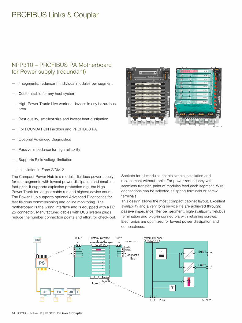
— 4 segments, individual modules per segment — Customizable cable connections to any PLC and PCS
hosts — High-Power Trunk: Live work on devices in any hazardous
area — Best quality, smallest size and lowest heat dissipation — For FOUNDATION Fieldbus and PROFIBUS PA — Optional Advanced Diagnostics — Passive impedance for high reliability — Supports Ex ic voltage limitation — Installation in Zone 2/Div. 2 Pos: 15.3 /Grid-Layout/++++++++++++ Spaltenumbruch ++++++++++++ @ 27\mod_1238577564630_0.docx @ 254475 @ @ 1
Pos: 15.4 /Grid-Layout/Technische Daten/Geräte-Management und Feldbus/NDL - PROFIBUS/NPP/Simplex Profibus PA/Einleitung/Abbildung Allgemeine Beschreibung @ 49\mod_1311155644186_3101.docx @ 409699 @ @ 1
Pos: 15.5 /Grid-Layout/++++++++++++ Wechsel von zwei- auf einspaltig ++++++++++++ @ 27\mod_1238577808304_0.docx @ 254523 @ @ 1
Change from two to one column Pos: 15.6 /Grid-Layout/++++++++++++ Wechsel von ein- auf zweispaltig ++++++++++++ @ 27\mod_1238577723694_0.docx @ 254499 @ @ 1 Change from one to two columns Pos: 15.7 /Grid-Layout/Technische Daten/Geräte-Management und Feldbus/NDL - PROFIBUS/NPP/Simplex Profibus PA/Einleitung/Allgemeine Beschreibung @ 98\mod_1483955077161_3101.docx @ 933496 @ @ 1
The Compact Power Hub is a modular fieldbus power supply for four segments with lowest power dissipation and smallest foot print. It supports explosion protection e.g. the High-Power Trunk for longest cable run and highest device count. The Power Hub supports optional Advanced Diagnostics for fast fieldbus commissioning and online monitoring. The motherboard is the wiring interface and is equipped with a DB 25 connector. Manufactured cables with DCS system plugs reduce the number connection points and effort for check-out.
Sockets for all modules enable simple installation and replacement without tools. Wire connections can be selected as spring terminals or screw terminals. This design allows the most compact cabinet layout. Excellent availability and a very long service life are achieved through: passive impedance filter per segment, high-availability fieldbus termination and plug-in connectors with retaining screws. Electronics are optimized for lowest power dissipation and compactness. Pos: 15.8 /Grid-Layout/++++++++++++ Wechsel von zwei- auf einspaltig ++++++++++++ @ 27\mod_1238577808304_0.docx @ 254523 @ @ 1
Change from two to one column Pos: 15.9 /Grid-Layout/Technische Daten/Geräte-Management und Feldbus/NDL - PROFIBUS/NPP/Simplex Profibus PA/Einleitung/Abbildung Allgemeine Beschreibung II @ 79\mod_1418218907197_3101.docx @ 668495 @ @ 1
Pos: 15.10 /Grid-Layout/++++++++++++ Wechsel von ein- auf zweispaltig ++++++++++++ @ 27\mod_1238577723694_0.docx @ 254499 @ @ 1 Change from one to two columns Pos: 15.11 /Grid-Layout/++++++++++++ Seitenumbruch ++++++++++++ @ 27\mod_1238577222488_0.docx @ 254391 @ @ 1

PROFIBUS Links & Coupler
12 DS/NDL-EN Rev. B | PROFIBUS Links & Coupler
Pos: 15.12 /Grid-Layout/Technische Daten/Geräte-Management und Feldbus/NDL - PROFIBUS/NPP/Simplex Profibus PA/Einleitung/Überschrift NPP310 simplex @ 49\mod_1311156269965_3101.docx @ 409771 @ 1 @ 1
NPP310 – PROFIBUS PA Motherboard for Power supply (simplex) Pos: 15.13 /Grid-Layout/Überschriften/1.1/S - U/Technische Daten @ 49\mod_1311076392227_3101.docx @ 408982 @ @ 1
Specifications Pos: 15.14 /Grid-Layout/Technische Daten/Geräte-Management und Feldbus/NDL - PROFIBUS/NPP/Simplex Profibus PA/Technische Daten/Technische Daten @ 98\mod_1483955347551_3101.docx @ 933524 @ @ 4
General specifications
Design / Mounting Motherboard based
Supply
Connection Redundant
Rated voltage Un 19.2 ... 35 V SELV/PELV
Rated current In 12 A
Power dissipation typ. 0.4 W per segment
Fieldbus interface
Number of segments 4 simplex
Host-side System specific cable connection
Terminating resistor 100 Ω integrated
Indicators / operating means
Fault signal VFC alarm 1 A, 50 V DC, normally
closed
Electrical isolation
Fieldbus segment / Fieldbus
segment
Functional insulation acc. to IEC
62103, rated insulation voltage
50 Veff
Fieldbus segment / Supply Functional insulation acc. to IEC
62103, rated insulation voltage
250 Veff
Directive conformity
Electromagnetic compatibility
Directive 2014/30/EU EN 61326-1:2013
Standard conformity
Electromagnetic compatibility NE 21:2011
Degree of protection IEC 60529
Fieldbus standard IEC 61158-2
Shock resistance EN 60068-2-27
Vibration resistance EN 60068-2-6
Ambient conditions
Ambient temperature -40 ... 70 °C (-40 ... 158 °F)
Storage temperature -40 ... 85 °C (-40 ... 185 °F)
Relative humidity < 95 % non-condensing
Shock resistance 10 g, 11 ms
Vibration resistance 1 g , 10 ... 150 Hz
Pollution Degree Max. 2, according to IEC 60664
Corrosion resistance Acc. to ISA-S71.04-1985, severity
level G3
Mechanical specifications
Connection type Plug-in terminals, screw terminals
Core cross-section 2.5 mm2
Housing material Polycarbonate
Degree of protection IP 20
Mass Approx. 540 g
Mounting DIN mounting rail
Data for application in connection with hazardous areas
Statement of conformity TÜV 10 ATEX 555761X
Group, category, type of
protection, temperature
classification
II 3 G Ex nA IIC T4 Gc
Directive conformity
Directive 2014/34/EU EN 60079-0:2012 , EN 60079-
11:2012 , EN 60079-15:2010
International approvals
FM approval CoC 3024816, CoC 3024816C
Approved for Class I, Division 2,
Groups A, B, C, D, T4 / Class I,
Zone 2, AEx/Ex nA IIC T4
IECEx approval IECEx TUN 13.0037X
Approved for Ex nA IIC T4 Gc
Marine approval DNV A-14038
Supplementary information Statement of Conformity, Declaration of Conformity, Attestation of Conformity and instructions have to be observed where applicable. Pos: 15.15 /Grid-Layout/++++++++++++ Seitenumbruch ++++++++++++ @ 27\mod_1238577222488_0.docx @ 254391 @ @ 1

PROFIBUS Links & Coupler | DS/NDL-EN Rev. B 13
Pos: 15.16 /Grid-Layout/++++++++++++ Wechsel von zwei- auf einspaltig ++++++++++++ @ 27\mod_1238577808304_0.docx @ 254523 @ @ 1 Change from two to one column Pos: 15.17 /Grid-Layout/Technische Daten/Geräte-Management und Feldbus/NDL - PROFIBUS/NPP/Simplex Profibus PA/Einleitung/Überschrift NPP310 simplex @ 49\mod_1311156269965_3101.docx @ 409771 @ 1 @ 1
NPP310 – PROFIBUS PA Motherboard for Power supply (simplex) Pos: 15.18 /Grid-Layout/Überschriften/1.1/M - O/Montageabmessungen @ 48\mod_1307436478312_3101.docx @ 403487 @ @ 1
Mounting dimensions Pos: 15.19 /Grid-Layout/Technische Daten/Geräte-Management und Feldbus/NDL - PROFIBUS/NPP/Simplex Profibus PA/Montageabmessungen/Montageabmessungen @ 98\mod_1483957504436_3101.docx @ 933552 @ @ 1
1 Motherboard
b Power supply modules
c Diagnostic module
d Mounting slot for DIN mounting rail
e Connections for alarm voltage-free contact and diagnostic bus
f Connections for fieldbus trunk
g Screening / earthing kit for trunk shields, optional accessory
h Connections for bulk power supply
i DB 25 connector for host via custom cable
Pos: 15.20 /Grid-Layout/Technische Daten/Geräte-Management und Feldbus/NDL - PROFIBUS/NPP/Simplex Profibus PA/Fußzeile "Based on" @ 98\mod_1483957770582_3101.docx @ 933580 @ @ 1
Based on 169684_ENG.xml / RD 2016-08-10 Pos: 16 /Grid-Layout/++++++++++++ Seitenumbruch ++++++++++++ @ 27\mod_1238577222488_0.docx @ 254391 @ @ 1
PROFIBUS Links & Coupler
14 DS/NDL-EN Rev. B | PROFIBUS Links & Coupler
Pos: 17 /Grid-Layout/++++++++++++ Wechsel von ein- auf zweispaltig ++++++++++++ @ 27\mod_1238577723694_0.docx @ 254499 @ @ 1 Change from one to two columns Pos: 18.1 /Grid-Layout/Technische Daten/Geräte-Management und Feldbus/NDL - PROFIBUS/NPP/Redundant/Einleitung/Überschrift NPP310 redundant @ 49\mod_1311160421772_3101.docx @ 410160 @ 1 @ 1
NPP310 – PROFIBUS PA Motherboard for Power supply (redundant) Pos: 18.2 /Grid-Layout/Technische Daten/Geräte-Management und Feldbus/NDL - PROFIBUS/NPP/Redundant/Einleitung/Einleitung @ 98\mod_1483958133379_3101.docx @ 933720 @ @ 1
— 4 segments, redundant, individual modules per segment — Customizable for any host system — High-Power Trunk: Live work on devices in any hazardous
area — Best quality, smallest size and lowest heat dissipation — For FOUNDATION Fieldbus and PROFIBUS PA — Optional Advanced Diagnostics — Passive impedance for high reliability — Supports Ex ic voltage limitation — Installation in Zone 2/Div. 2
Pos: 18.3 /Grid-Layout/Technische Daten/Geräte-Management und Feldbus/NDL - PROFIBUS/NPP/Redundant/Einleitung/Abbildung Allgemeine Beschreibung @ 79\mod_1417694971196_3101.docx @ 665944 @ @ 1
Pos: 18.4 /Grid-Layout/++++++++++++ Wechsel von zwei- auf einspaltig ++++++++++++ @ 27\mod_1238577808304_0.docx @ 254523 @ @ 1
Change from two to one column Pos: 18.5 /Grid-Layout/++++++++++++ Wechsel von ein- auf zweispaltig ++++++++++++ @ 27\mod_1238577723694_0.docx @ 254499 @ @ 1 Change from one to two columns Pos: 18.6 /Grid-Layout/Technische Daten/Geräte-Management und Feldbus/NDL - PROFIBUS/NPP/Redundant/Einleitung/Allgemeine Beschreibung @ 98\mod_1483958477973_3101.docx @ 933748 @ @ 1
The Compact Power Hub is a modular fieldbus power supply for four segments with lowest power dissipation and smallest foot print. It supports explosion protection e.g. the High-Power Trunk for longest cable run and highest device count. The Power Hub supports optional Advanced Diagnostics for fast fieldbus commissioning and online monitoring. The motherboard is the wiring interface and is equipped with a DB 25 connector. Manufactured cables with DCS system plugs reduce the number connection points and effort for check-out.
Sockets for all modules enable simple installation and replacement without tools. For power redundancy with seamless transfer, pairs of modules feed each segment. Wire connections can be selected as spring terminals or screw terminals. This design allows the most compact cabinet layout. Excellent availability and a very long service life are achieved through: passive impedance filter per segment, high-availability fieldbus termination and plug-in connectors with retaining screws. Electronics are optimized for lowest power dissipation and compactness. Pos: 18.7 /Grid-Layout/++++++++++++ Wechsel von zwei- auf einspaltig ++++++++++++ @ 27\mod_1238577808304_0.docx @ 254523 @ @ 1
Change from two to one column Pos: 18.8 /Grid-Layout/Technische Daten/Geräte-Management und Feldbus/NDL - PROFIBUS/NPP/Redundant/Einleitung/Abbildung Allgemeine Beschreibung II @ 79\mod_1418218983015_3101.docx @ 668523 @ @ 1
Pos: 18.9 /Grid-Layout/++++++++++++ Wechsel von ein- auf zweispaltig ++++++++++++ @ 27\mod_1238577723694_0.docx @ 254499 @ @ 1 Change from one to two columns Pos: 18.10 /Grid-Layout/++++++++++++ Seitenumbruch ++++++++++++ @ 27\mod_1238577222488_0.docx @ 254391 @ @ 1

PROFIBUS Links & Coupler | DS/NDL-EN Rev. B 15
Pos: 18.11 /Grid-Layout/Technische Daten/Geräte-Management und Feldbus/NDL - PROFIBUS/NPP/Redundant/Einleitung/Überschrift NPP310 redundant @ 49\mod_1311160421772_3101.docx @ 410160 @ 1 @ 1
NPP310 – PROFIBUS PA Motherboard for Power supply (redundant) Pos: 18.12 /Grid-Layout/Überschriften/1.1/S - U/Technische Daten @ 49\mod_1311076392227_3101.docx @ 408982 @ @ 1
Specifications Pos: 18.13 /Grid-Layout/Technische Daten/Geräte-Management und Feldbus/NDL - PROFIBUS/NPP/Redundant/Technische Daten/Technische Daten @ 98\mod_1483958730024_3101.docx @ 933776 @ @ 4
General specifications
Design / Mounting Motherboard based
Supply
Connection Redundant
Rated voltage Un 19.2 ... 35 V SELV/PELV
Rated current In 12 A
Power dissipation Typ. 0.4 W per segment
Fieldbus interface
Number of segments 4 redundant
Host-side System specific cable connection
Terminating resistor 100 Ω integrated
Indicators / operating means
Fault signal VFC alarm 1 A, 50 V DC, normally
closed
Electrical isolation
Fieldbus segment / Fieldbus
segment
Functional insulation acc. to IEC
62103, rated insulation voltage
50 Veff
Fieldbus segment / Supply Functional insulation acc. to IEC
62103, rated insulation voltage
250 Veff
Directive conformity
Electromagnetic compatibility
Directive 2014/30/EU EN 61326-1:2013
Standard conformity
Electromagnetic compatibility NE 21:2011
Degree of protection IEC 60529
Fieldbus standard IEC 61158-2
Shock resistance EN 60068-2-27
Vibration resistance EN 60068-2-6
Ambient conditions
Ambient temperature -40 ... 70 °C (-40 ... 158 °F)
Storage temperature -40 ... 85 °C (-40 ... 185 °F)
Relative humidity < 95 % non-condensing
Shock resistance 10 g 11 ms
Vibration resistance 1 g , 10 ... 150 Hz
Pollution Degree Max. 2, according to IEC 60664
Corrosion resistance Acc. to ISA-S71.04-1985, severity
level G3
Mechanical specifications
Connection type Plug-in terminals, screw terminal
Core cross-section 2.5 mm2
Housing material Polycarbonate
Degree of protection IP 20
Mass Approx. 580 g
Mounting DIN mounting rail
Data for application in connection with hazardous areas
Statement of conformity TÜV 10 ATEX 555761X
Group, category, type of
protection, temperature
classification
II 3 G Ex nA IIC T4 Gc
Directive conformity
Directive 2014/34/EU EN 60079-0:2012 , EN 60079-
11:2012 , EN 60079-15:2010
International approvals
FM approval CoC 3024816, CoC 3024816C
Approved for Class I, Division 2,
Groups A, B, C, D, T4 / Class I,
Zone 2, AEx/Ex nA IIC T4
IECEx approval IECEx TUN 13.0037X
Approved for Ex nA IIC T4 Gc
Marine approval DNV A-14038
Supplementary information Statement of Conformity, Declaration of Conformity, Attestation of Conformity and instructions have to be observed where applicable. Pos: 18.14 /Grid-Layout/++++++++++++ Seitenumbruch ++++++++++++ @ 27\mod_1238577222488_0.docx @ 254391 @ @ 1

PROFIBUS Links & Coupler
16 DS/NDL-EN Rev. B | PROFIBUS Links & Coupler
Pos: 18.15 /Grid-Layout/++++++++++++ Wechsel von zwei- auf einspaltig ++++++++++++ @ 27\mod_1238577808304_0.docx @ 254523 @ @ 1 Change from two to one column Pos: 18.16 /Grid-Layout/Technische Daten/Geräte-Management und Feldbus/NDL - PROFIBUS/NPP/Redundant/Einleitung/Überschrift NPP310 redundant @ 49\mod_1311160421772_3101.docx @ 410160 @ 1 @ 1
NPP310 – PROFIBUS PA Motherboard for Power supply (redundant) Pos: 18.17 /Grid-Layout/Überschriften/1.1/M - O/Montageabmessungen @ 48\mod_1307436478312_3101.docx @ 403487 @ @ 1
Mounting dimensions Pos: 18.18 /Grid-Layout/Technische Daten/Geräte-Management und Feldbus/NDL - PROFIBUS/NPP/Redundant/Montageabmessungen/Montageabmessungen @ 98\mod_1483960028231_3101.docx @ 933804 @ @ 1
1 Motherboard
b Power supply modules
c Diagnostic module
d Mounting slot for DIN mounting rail
e Connections for alarm voltage-free contact and diagnostic bus
f Connections for fieldbus trunk
g Screening / earthing kit for trunk shields, optional accessory
h Connections for bulk power supply
i DB 25 connector for host via custom cable
Pos: 18.19 /Grid-Layout/Technische Daten/Geräte-Management und Feldbus/NDL - PROFIBUS/NPP/Redundant/Fußzeile "Based on" @ 98\mod_1483960433072_3101.docx @ 933832 @ @ 4
Based on 169683_ENG.xml / RD 2016-08-10 Pos: 19 /Grid-Layout/++++++++++++ Seitenumbruch ++++++++++++ @ 27\mod_1238577222488_0.docx @ 254391 @ @ 1
PROFIBUS Links & Coupler | DS/NDL-EN Rev. B 17
Pos: 20 /Grid-Layout/++++++++++++ Wechsel von ein- auf zweispaltig ++++++++++++ @ 27\mod_1238577723694_0.docx @ 254499 @ @ 1 Change from one to two columns Pos: 21.1 /Grid-Layout/Technische Daten/Geräte-Management und Feldbus/NDL - PROFIBUS/NPP/Simplex Profibus/Einleitung/Überschrift NPP310 simplex @ 98\mod_1483964960892_3101.docx @ 934094 @ 1 @ 1
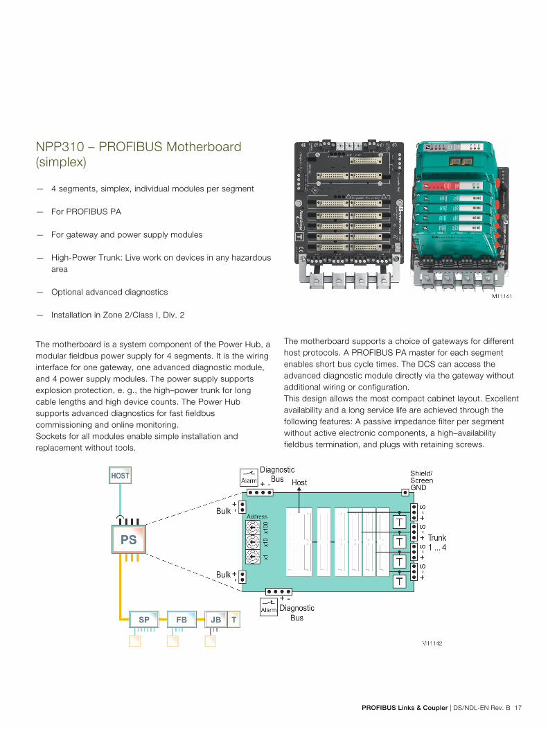
NPP310 – PROFIBUS Motherboard (simplex) Pos: 21.2 /Grid-Layout/Technische Daten/Geräte-Management und Feldbus/NDL - PROFIBUS/NPP/Simplex Profibus/Einleitung/Einleitung @ 98\mod_1483964952616_3101.docx @ 934066 @ @ 1
— 4 segments, simplex, individual modules per segment — For PROFIBUS PA — For gateway and power supply modules — High-Power Trunk: Live work on devices in any hazardous
area — Optional advanced diagnostics — Installation in Zone 2/Class I, Div. 2 Pos: 21.3 /Grid-Layout/Technische Daten/Geräte-Management und Feldbus/NDL - PROFIBUS/NPP/Simplex Profibus/Einleitung/Abbildung Allgemeine Beschreibung @ 98\mod_1483964897096_3101.docx @ 933972 @ @ 1
Pos: 21.4 /Grid-Layout/++++++++++++ Wechsel von zwei- auf einspaltig ++++++++++++ @ 27\mod_1238577808304_0.docx @ 254523 @ @ 1
Change from two to one column Pos: 21.5 /Grid-Layout/++++++++++++ Wechsel von ein- auf zweispaltig ++++++++++++ @ 27\mod_1238577723694_0.docx @ 254499 @ @ 1 Change from one to two columns Pos: 21.6 /Grid-Layout/++++++++++++ Absatzmarke (einzeln) ++++++++++++ @ 56\mod_1329208232428_0.docx @ 484352 @ @ 1 Pos: 21.7 /Grid-Layout/Technische Daten/Geräte-Management und Feldbus/NDL - PROFIBUS/NPP/Simplex Profibus/Einleitung/Allgemeine Beschreibung @ 98\mod_1483964933961_3101.docx @ 934038 @ @ 1
The motherboard is a system component of the Power Hub, a modular fieldbus power supply for 4 segments. It is the wiring interface for one gateway, one advanced diagnostic module, and 4 power supply modules. The power supply supports explosion protection, e. g., the high–power trunk for long cable lengths and high device counts. The Power Hub supports advanced diagnostics for fast fieldbus commissioning and online monitoring. Sockets for all modules enable simple installation and replacement without tools.
The motherboard supports a choice of gateways for different host protocols. A PROFIBUS PA master for each segment enables short bus cycle times. The DCS can access the advanced diagnostic module directly via the gateway without additional wiring or configuration. This design allows the most compact cabinet layout. Excellent availability and a long service life are achieved through the following features: A passive impedance filter per segment without active electronic components, a high–availability fieldbus termination, and plugs with retaining screws. Pos: 21.8 /Grid-Layout/++++++++++++ Wechsel von zwei- auf einspaltig ++++++++++++ @ 27\mod_1238577808304_0.docx @ 254523 @ @ 1
Change from two to one column Pos: 21.9 /Grid-Layout/Technische Daten/Geräte-Management und Feldbus/NDL - PROFIBUS/NPP/Simplex Profibus/Einleitung/Abbildung Allgemeine Beschreibung II @ 98\mod_1483964908415_3101.docx @ 934010 @ @ 1
Pos: 21.10 /Grid-Layout/++++++++++++ Wechsel von ein- auf zweispaltig ++++++++++++ @ 27\mod_1238577723694_0.docx @ 254499 @ @ 1 Change from one to two columns Pos: 21.11 /Grid-Layout/++++++++++++ Seitenumbruch ++++++++++++ @ 27\mod_1238577222488_0.docx @ 254391 @ @ 1

PROFIBUS Links & Coupler
18 DS/NDL-EN Rev. B | PROFIBUS Links & Coupler
Pos: 21.12 /Grid-Layout/Technische Daten/Geräte-Management und Feldbus/NDL - PROFIBUS/NPP/Simplex Profibus/Einleitung/Überschrift NPP310 simplex @ 98\mod_1483964960892_3101.docx @ 934094 @ 1 @ 1
NPP310 – PROFIBUS Motherboard (simplex) Pos: 21.13 /Grid-Layout/Überschriften/1.1/S - U/Technische Daten @ 49\mod_1311076392227_3101.docx @ 408982 @ @ 1
Specifications Pos: 21.14 /Grid-Layout/Technische Daten/Geräte-Management und Feldbus/NDL - PROFIBUS/NPP/Simplex Profibus/Technische Daten/Technische Daten @ 98\mod_1483965448682_3101.docx @ 934151 @ @ 4
General specifications
Design / Mounting Motherboard based
Supply
Connection Redundant
Rated voltage Un 19.2 ... 35 V SELV/PELV
Rated current In 12 A
Power dissipation Typ. 0.4 W per segment
Fieldbus interface
Number of segments 4 simplex
Terminating resistor 100 Ω integrated
Indicators / operating means
Fault signal VFC alarm 1 A, 50 V DC, normally
closed
Rotary switch Bus addressing, gateway-specific
Electrical isolation
Fieldbus segment / Fieldbus
segment
Functional insulation acc. to IEC
61010, rated insulation voltage
50 Veff
Fieldbus segment / Supply Functional insulation acc. to IEC
61010, rated insulation voltage
50 Veff
Directive conformity
Electromagnetic compatibility
Directive 2014/30/EU EN 61326-1:2013
Standard conformity
Electromagnetic compatibility NE 21:2011
Degree of protection IEC 60529
Fieldbus standard IEC 61158-2
Shock resistance EN 60068-2-27
Vibration resistance EN 60068-2-6
Ambient conditions
Ambient temperature -40 ... 70 °C (-40 ... 158 °F)
Storage temperature -40 ... 85 °C (-40 ... 185 °F)
Relative humidity < 95 % non-condensing
Shock resistance 10 g, 11 ms
Vibration resistance 1 g , 10 ... 150 Hz
Pollution Degree Max. 2, according to IEC 60664
Corrosion resistance Acc. to ISA-S71.04-1985, severity
level G3
Mechanical specifications
Connection type Plug-in terminals, screw terminals
Core cross-section 2.5 mm2
Housing material Polycarbonate
Degree of protection IP 20
Mass Approx. 540 g
Mounting DIN mounting rail
Data for application in connection with hazardous areas
Statement of conformity TÜV 15 ATEX 7735 X
Group, category, type of
protection, temperature
classification
II 3G Ex ec IIC T4 Gc
Directive conformity
Directive 2014/34/EU EN 60079-0:2012 , EN 60079-
7:2015 , EN 60079-11:2012
International approvals
IECEx approval IECEx TUR 16.0007X
Approved for Ex ec IIC T4 Gc
Marine approval Pending
Supplementary information Statement of Conformity, Declaration of Conformity, Attestation of Conformity and instructions have to be observed where applicable. Pos: 21.15 /Grid-Layout/++++++++++++ Seitenumbruch ++++++++++++ @ 27\mod_1238577222488_0.docx @ 254391 @ @ 1

PROFIBUS Links & Coupler | DS/NDL-EN Rev. B 19
Pos: 21.16 /Grid-Layout/++++++++++++ Wechsel von zwei- auf einspaltig ++++++++++++ @ 27\mod_1238577808304_0.docx @ 254523 @ @ 1 Change from two to one column Pos: 21.17 /Grid-Layout/Technische Daten/Geräte-Management und Feldbus/NDL - PROFIBUS/NPP/Simplex Profibus/Einleitung/Überschrift NPP310 simplex @ 98\mod_1483964960892_3101.docx @ 934094 @ 1 @ 1
NPP310 – PROFIBUS Motherboard (simplex) Pos: 21.18 /Grid-Layout/Überschriften/1.1/M - O/Montageabmessungen @ 48\mod_1307436478312_3101.docx @ 403487 @ @ 1
Mounting dimensions Pos: 21.19 /Grid-Layout/Technische Daten/Geräte-Management und Feldbus/NDL - PROFIBUS/NPP/Simplex Profibus/Montageabmessungen/Montageabmessungen @ 98\mod_1483966065191_3101.docx @ 934207 @ @ 1
1 Motherboard
b Gateway module
c Diagnostic module
d Power supply modules (x 4)
e Trunk connection
f Shielding/grounding kit for trunk shields, optional accessory
g Connections: Volt-free contact alarm and diagnostic bus (x 2)
h Connection for bulk power supply (x 2)
i Rotary switches for gateway addressing x1, x10, x100
j Shield connection
k Mounting slot for DIN rail mounting
Pos: 21.20 /Grid-Layout/Technische Daten/Geräte-Management und Feldbus/NDL - PROFIBUS/NPP/Simplex Profibus/Fußzeile "Based on" @ 98\mod_1483966311347_3101.docx @ 934235 @ @ 1
Based on 177582_ENG.xml / RD 2016-08-08 Pos: 22 /Grid-Layout/++++++++++++ Seitenumbruch ++++++++++++ @ 27\mod_1238577222488_0.docx @ 254391 @ @ 1
PROFIBUS Links & Coupler
20 DS/NDL-EN Rev. B | PROFIBUS Links & Coupler
Pos: 23 /Grid-Layout/++++++++++++ Wechsel von ein- auf zweispaltig ++++++++++++ @ 27\mod_1238577723694_0.docx @ 254499 @ @ 1 Change from one to two columns Pos: 24.1 /Grid-Layout/Technische Daten/Geräte-Management und Feldbus/NDL - PROFIBUS/NGP/L0150/Einleitung/Überschrift NGP310 (L0150) @ 98\mod_1483967269830_3101.docx @ 934291 @ 1 @ 1
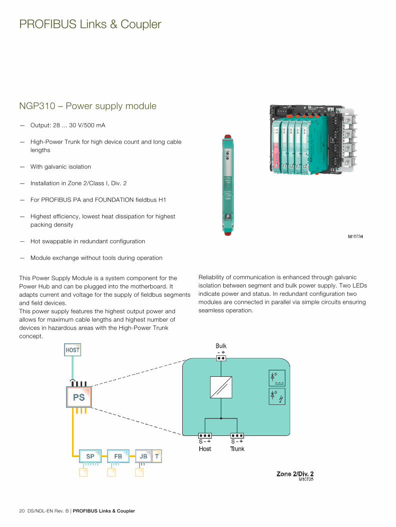
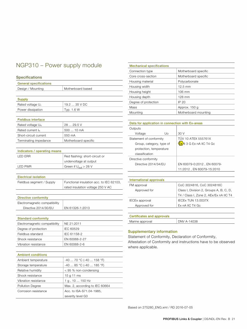
NGP310 – Power supply module Pos: 24.2 /Grid-Layout/Technische Daten/Geräte-Management und Feldbus/NDL - PROFIBUS/NGP/L0150/Einleitung/Einleitung @ 98\mod_1483967403439_3101.docx @ 934320 @ @ 1
— Output: 28 ... 30 V/500 mA — High-Power Trunk for high device count and long cable
lengths — With galvanic isolation — Installation in Zone 2/Class I, Div. 2 — For PROFIBUS PA and FOUNDATION fieldbus H1 — Highest efficiency, lowest heat dissipation for highest
packing density — Hot swappable in redundant configuration — Module exchange without tools during operation Pos: 24.3 /Grid-Layout/Technische Daten/Geräte-Management und Feldbus/NDL - PROFIBUS/NGP/L0150/Einleitung/Abbildung Allgemeine Beschreibung @ 49\mod_1311233976653_3101.docx @ 410684 @ @ 1
Pos: 24.4 /Grid-Layout/++++++++++++ Wechsel von zwei- auf einspaltig ++++++++++++ @ 27\mod_1238577808304_0.docx @ 254523 @ @ 1
Change from two to one column Pos: 24.5 /Grid-Layout/++++++++++++ Wechsel von ein- auf zweispaltig ++++++++++++ @ 27\mod_1238577723694_0.docx @ 254499 @ @ 1 Change from one to two columns Pos: 24.6 /Grid-Layout/Technische Daten/Geräte-Management und Feldbus/NDL - PROFIBUS/NGP/L0150/Einleitung/Allgemeine Beschreibung @ 79\mod_1417696930593_3101.docx @ 666124 @ @ 1
This Power Supply Module is a system component for the Power Hub and can be plugged into the motherboard. It adapts current and voltage for the supply of fieldbus segments and field devices. This power supply features the highest output power and allows for maximum cable lengths and highest number of devices in hazardous areas with the High-Power Trunk concept.
Reliability of communication is enhanced through galvanic isolation between segment and bulk power supply. Two LEDs indicate power and status. In redundant configuration two modules are connected in parallel via simple circuits ensuring seamless operation. Pos: 24.7 /Grid-Layout/++++++++++++ Wechsel von zwei- auf einspaltig ++++++++++++ @ 27\mod_1238577808304_0.docx @ 254523 @ @ 1
Change from two to one column Pos: 24.8 /Grid-Layout/Technische Daten/Geräte-Management und Feldbus/NDL - PROFIBUS/NGP/L0150/Einleitung/Abbildung Allgemeine Beschreibung II @ 98\mod_1484229038677_3101.docx @ 934934 @ @ 1
Pos: 24.9 /Grid-Layout/++++++++++++ Wechsel von ein- auf zweispaltig ++++++++++++ @ 27\mod_1238577723694_0.docx @ 254499 @ @ 1 Change from one to two columns Pos: 24.10 /Grid-Layout/++++++++++++ Seitenumbruch ++++++++++++ @ 27\mod_1238577222488_0.docx @ 254391 @ @ 1
PROFIBUS Links & Coupler | DS/NDL-EN Rev. B 21
Pos: 24.11 /Grid-Layout/Technische Daten/Geräte-Management und Feldbus/NDL - PROFIBUS/NGP/L0150/Einleitung/Überschrift NGP310 (L0150) @ 98\mod_1483967269830_3101.docx @ 934291 @ 1 @ 1
NGP310 – Power supply module Pos: 24.12 /Grid-Layout/Überschriften/1.1/S - U/Technische Daten @ 49\mod_1311076392227_3101.docx @ 408982 @ @ 1
Specifications Pos: 24.13 /Grid-Layout/Technische Daten/Geräte-Management und Feldbus/NDL - PROFIBUS/NGP/L0150/Technische Daten/Technische Daten @ 98\mod_1483967642750_3101.docx @ 934348 @ @ 1
General specifications
Design / Mounting Motherboard based
Supply
Rated voltage Un 19.2 ... 35 V DC
Power dissipation Typ. 1.6 W
Fieldbus interface
Rated voltage UN 28 ... 29.5 V
Rated current IN 500 ... 10 mA
Short-circuit current 550 mA
Terminating impedance Motherboard specific
Indicators / operating means
LED ERR Red flashing: short-circuit or
undervoltage at output
LED PWR Green if Uout > 28 V
Electrical isolation
Fieldbus segment / Supply Functional insulation acc. to IEC 62103,
rated insulation voltage 250 V AC
Directive conformity
Electromagnetic compatibility
Directive 2014/30/EU EN 61326-1:2013
Standard conformity
Electromagnetic compatibility NE 21:2011
Degree of protection IEC 60529
Fieldbus standard IEC 61158-2
Shock resistance EN 60068-2-27
Vibration resistance EN 60068-2-6
Ambient conditions
Ambient temperature -40 ... 70 °C (-40 ... 158 °F)
Storage temperature -40 ... 85 °C (-40 ... 185 °F)
Relative humidity < 95 % non-condensing
Shock resistance 15 g 11 ms
Vibration resistance 1 g , 10 ... 150 Hz
Pollution Degree Max. 2, according to IEC 60664
Corrosion resistance Acc. to ISA-S71.04-1985,
severity level G3
Mechanical specifications
Connection type Motherboard specific
Core cross-section Motherboard specific
Housing material Polycarbonate
Housing width 12.5 mm
Housing height 106 mm
Housing depth 128 mm
Degree of protection IP 20
Mass Approx. 150 g
Mounting Motherboard mounting
Data for application in connection with Ex-areas
Outputs
Voltage Uo 30 V
Statement of conformity TÜV 10 ATEX 555761X
Group, category, type of
protection, temperature
classification
II 3 G Ex nA IIC T4 Gc
Directive conformity
Directive 2014/34/EU EN 60079-0:2012 , EN 60079-
11:2012 , EN 60079-15:2010
International approvals
FM approval CoC 3024816, CoC 3024816C
Approved for Class I, Division 2, Groups A, B, C, D,
T4 / Class I, Zone 2, AEx/Ex nA IIC T4
IECEx approval IECEx TUN 13.0037X
Approved for Ex nA IIC T4 Gc
Certificates and approvals
Marine approval DNV A-14038
Supplementary information Statement of Conformity, Declaration of Conformity, Attestation of Conformity and instructions have to be observed where applicable. Pos: 24.14 /Grid-Layout/Technische Daten/Geräte-Management und Feldbus/NDL - PROFIBUS/NGP/L0150/Fußzeile "Based on" @ 98\mod_1483968311189_3101.docx @ 934376 @ @ 4
Based on 275280_ENG.xml / RD 2016-07-05 Pos: 25 /Grid-Layout/++++++++++++ Seitenumbruch ++++++++++++ @ 27\mod_1238577222488_0.docx @ 254391 @ @ 1

PROFIBUS Links & Coupler
22 DS/NDL-EN Rev. B | PROFIBUS Links & Coupler
Pos: 26 /Grid-Layout/++++++++++++ Wechsel von ein- auf zweispaltig ++++++++++++ @ 27\mod_1238577723694_0.docx @ 254499 @ @ 1 Change from one to two columns Pos: 27.1 /Grid-Layout/Technische Daten/Geräte-Management und Feldbus/NDL - PROFIBUS/NGP/Basic/Einleitung/Überschrift NGP312 basic @ 49\mod_1311236375112_3101.docx @ 410904 @ 1 @ 1
NGP312 – Diagnostic module basic Pos: 27.2 /Grid-Layout/Technische Daten/Geräte-Management und Feldbus/NDL - PROFIBUS/NGP/Basic/Einleitung/Einleitung @ 79\mod_1418025696348_3101.docx @ 666688 @ @ 1
— Basic monitoring for power supply output and health — Plug-in Module for the Power Hub — Plug and play - no engineering required — For online monitoring — For FOUNDATION fieldbus-H1 and PROFIBUS PA — Installation in Zone 2/Class I, Div. 2 — System state and fault indication via LEDs Pos: 27.3 /Grid-Layout/Technische Daten/Geräte-Management und Feldbus/NDL - PROFIBUS/NGP/Basic/Einleitung/Abbildung Allgemeine Beschreibung @ 49\mod_1311236294253_3101.docx @ 410880 @ @ 1
Pos: 27.4 /Grid-Layout/++++++++++++ Wechsel von zwei- auf einspaltig ++++++++++++ @ 27\mod_1238577808304_0.docx @ 254523 @ @ 1
Change from two to one column Pos: 27.5 /Grid-Layout/++++++++++++ Wechsel von ein- auf zweispaltig ++++++++++++ @ 27\mod_1238577723694_0.docx @ 254499 @ @ 1 Change from one to two columns Pos: 27.6 /Grid-Layout/Technische Daten/Geräte-Management und Feldbus/NDL - PROFIBUS/NGP/Basic/Einleitung/Allgemeine Beschreibung @ 49\mod_1311236143191_3101.docx @ 410856 @ @ 1
Designed as a plug-in module for the Power Hub, the Basic Diagnostic Module provides basic system diagnostics. It checks for proper operation of bulk power supplies and monitors the connected trunks for overload or short-circuit conditions. All Power Hub modules are checked for proper function. On redundant power modules it indicates missmatching pairs.
The module indicates a fault condition via voltage-free contact. It provides monitoring "plug-and-play" without additional engineering. LED signals indicate a fault for easy detection. Pos: 27.7 /Grid-Layout/++++++++++++ Wechsel von zwei- auf einspaltig ++++++++++++ @ 27\mod_1238577808304_0.docx @ 254523 @ @ 1
Change from two to one column Pos: 27.8 /Grid-Layout/Technische Daten/Geräte-Management und Feldbus/NDL - PROFIBUS/NGP/Basic/Einleitung/Abbildung Allgemeine Beschreibung II @ 79\mod_1418219081145_3101.docx @ 668551 @ @ 1
Pos: 27.9 /Grid-Layout/++++++++++++ Wechsel von ein- auf zweispaltig ++++++++++++ @ 27\mod_1238577723694_0.docx @ 254499 @ @ 1 Change from one to two columns Pos: 27.10 /Grid-Layout/++++++++++++ Seitenumbruch ++++++++++++ @ 27\mod_1238577222488_0.docx @ 254391 @ @ 1

PROFIBUS Links & Coupler | DS/NDL-EN Rev. B 23
Pos: 27.11 /Grid-Layout/Technische Daten/Geräte-Management und Feldbus/NDL - PROFIBUS/NGP/Basic/Einleitung/Überschrift NGP312 basic @ 49\mod_1311236375112_3101.docx @ 410904 @ 1 @ 1
NGP312 – Diagnostic module basic Pos: 27.12 /Grid-Layout/Überschriften/1.1/S - U/Technische Daten @ 49\mod_1311076392227_3101.docx @ 408982 @ @ 1
Specifications Pos: 27.13 /Grid-Layout/Technische Daten/Geräte-Management und Feldbus/NDL - PROFIBUS/NGP/Basic/Technische Daten/Technische Daten @ 98\mod_1484119040847_3101.docx @ 934468 @ @ 1
General specifications
Design / Mounting Motherboard based
Supply
Rated voltage Un 19.2 ... 35 V
Rated current In 20 mA
Power dissipation Max. 0.5 W
Indicators / operating means
LED PRI PWR Green: on, primary bulk power
supply connected
LED SEC PWR Green: on, secondary bulk power
supply connected
LED ERR Red: 2 Hz flashing, power supply
fault (short-circuit, undervoltage),
redundancy fault
Fault signal VFC alarm 1 A, 50 V DC, normally
closed
Electrical isolation
Fieldbus segment / Fieldbus
segment
Functional insulation acc. to
IEC 62103, rated insulation voltage
50 Veff
Directive conformity
Electromagnetic compatibility
Directive 2014/30/EU EN 61326-1:2013
Standard conformity
Electromagnetic compatibility NE 21:2011
Degree of protection IEC 60529
Shock resistance EN 60068-2-27
Vibration resistance EN 60068-2-6
Ambient conditions
Ambient temperature -40 ... 70 °C (-40 ... 158 °F)
Storage temperature -40 ... 85 °C (-40 ... 185 °F)
Relative humidity < 95 % non-condensing
Shock resistance 15 g 11 ms
Vibration resistance 1 g , 10 ... 150 Hz
Pollution Degree Max. 2, according to IEC 60664
Corrosion resistance Acc. to ISA-S71.04-1985, severity
level G3
Mechanical specifications
Connection type Motherboard specific
Core cross-section Motherboard specific
Housing material Polycarbonate
Housing width 18 mm
Housing height 106 mm
Housing depth 128 mm
Degree of protection IP 20
Mass Approx. 70 g
Mounting Motherboard mounting
Data for application in connection with Ex-areas
Statement of conformity TÜV 04 ATEX 2500 X
Group, category, type of
protection, temperature
classification
II 3 G Ex nA nC IIC T4 Gc
Directive conformity
Directive 2014/34/EU EN 60079-0:2012 , EN 60079-
11:2012 , EN 60079-15:2010
International approvals
FM approval CoC 3024816, CoC 3024816C
Approved for Class I, Division 2, Groups A, B, C,
D, T4 / Class I, Zone 2, AEx/Ex nC
IIC T4
IECEx approval IECEx TUN 13.0038X
Approved for Ex nA nC IIC T4 Gc
Certificates and approvals
Marine approval DNV A-14038
Supplementary information Statement of Conformity, Declaration of Conformity, Attestation of Conformity and instructions have to be observed where applicable. Pos: 27.14 /Grid-Layout/++++++++++++ Seitenumbruch ++++++++++++ @ 27\mod_1238577222488_0.docx @ 254391 @ @ 1

PROFIBUS Links & Coupler
24 DS/NDL-EN Rev. B | PROFIBUS Links & Coupler
Pos: 27.15 /Grid-Layout/++++++++++++ Wechsel von zwei- auf einspaltig ++++++++++++ @ 27\mod_1238577808304_0.docx @ 254523 @ @ 1 Change from two to one column Pos: 27.16 /Grid-Layout/Technische Daten/Geräte-Management und Feldbus/NDL - PROFIBUS/NGP/Basic/Einleitung/Überschrift NGP312 basic @ 49\mod_1311236375112_3101.docx @ 410904 @ 1 @ 1
NGP312 – Diagnostic module basic Pos: 27.17 /Grid-Layout/Überschriften/1.1/M - O/Montageabmessungen @ 48\mod_1307436478312_3101.docx @ 403487 @ @ 1
Mounting dimensions Pos: 27.18 /Grid-Layout/Technische Daten/Geräte-Management und Feldbus/NDL - PROFIBUS/NGP/Basic/Montageabmessungen/Montageabmessungen @ 79\mod_1421050460623_3101.docx @ 676242 @ @ 1
Dimensions complete redundant system
Dimensions Diagnostics Module 1 Power Supply Modules, see separate data sheets
b Diagnostics Module
c Connections for fieldbus trunk, terminator switch
d Screening / earthing kit for trunk cables shield, optional accessory
e Mounting slot for DIN rail
f Motherboard, see separate data sheets
g Connections for alarm, voltage free contact and diagnostics bus
h Connections for redundant host
i Connections for redundant bulk power supply
j Plug connections to Motherboard
k State and fault indication LEDs
Pos: 27.19 /Grid-Layout/Technische Daten/Geräte-Management und Feldbus/NDL - PROFIBUS/NGP/Basic/Fußzeile "Based on" @ 98\mod_1484119534938_3101.docx @ 934496 @ @ 1
Based on 131001_ENG.xml / RD 2016-04-19 Pos: 28 /Grid-Layout/++++++++++++ Seitenumbruch ++++++++++++ @ 27\mod_1238577222488_0.docx @ 254391 @ @ 1

PROFIBUS Links & Coupler | DS/NDL-EN Rev. B 25
Pos: 29 /Grid-Layout/++++++++++++ Wechsel von ein- auf zweispaltig ++++++++++++ @ 27\mod_1238577723694_0.docx @ 254499 @ @ 1 Change from one to two columns Pos: 30.1 /Grid-Layout/Technische Daten/Geräte-Management und Feldbus/NDL - PROFIBUS/NGP/Advanced/Einleitung/Überschrift NGP312 advanced @ 49\mod_1311240700851_3101.docx @ 411225 @ 1 @ 1
NGP312 – Diagnostic module advanced Pos: 30.2 /Grid-Layout/Technische Daten/Geräte-Management und Feldbus/NDL - PROFIBUS/NGP/Advanced/Einleitung/Einleitung @ 79\mod_1418027822616_3101.docx @ 666772 @ @ 1
— Comprehensive diagnostics for fieldbus physical layer and power supply
— Plug-in Module for the Power Hub — Precise measurements through passive circuits — For commissioning, online monitoring and troubleshooting — For FOUNDATION fieldbus-H1 and PROFIBUS PA — Installation in Zone 2/Class I, Div. 2 — System state and fault indication via LEDs — Display of data in the safety of the control room — Automatic setup of diagnostic system — Full software integration into DCS and PAM possible Pos: null /Grid-Layout/++++++++++++ Spaltenumbruch ++++++++++++ @ 27\mod_1238577564630_0.docx @ 254475 @ @ 1
Pos: 30.4 /Grid-Layout/Technische Daten/Geräte-Management und Feldbus/NDL - PROFIBUS/NGP/Advanced/Einleitung/Abbildung Allgemeine Beschreibung @ 49\mod_1311240844644_3101.docx @ 411249 @ @ 1
Pos: 30.5 /Grid-Layout/++++++++++++ Wechsel von zwei- auf einspaltig ++++++++++++ @ 27\mod_1238577808304_0.docx @ 254523 @ @ 1
Change from two to one column Pos: 30.6 /Grid-Layout/++++++++++++ Wechsel von ein- auf zweispaltig ++++++++++++ @ 27\mod_1238577723694_0.docx @ 254499 @ @ 1 Change from one to two columns Pos: 30.7 /Grid-Layout/Technische Daten/Geräte-Management und Feldbus/NDL - PROFIBUS/NGP/Advanced/Einleitung/Allgemeine Beschreibung @ 98\mod_1484121695997_3101.docx @ 934580 @ @ 1
Designed as a plug-in module for the Power Hub, this Advanced Diagnostic Module (ADM) is a comprehensive measurement tool for the physical layer of up to four fieldbus segments. It's passive input circuits leave the physical layer untouched for exact data. The ADM detects gradual or sudden changes and helps trace even intermittent malfunctions. The ADM supports commissioning, online monitoring and troubleshooting.
It can be integrated tightly into the DCS and PAM via a separate diagnostic bus, making the fieldbus physical layer itself a managable asset. Configuration tools automate setup of the ADM and of selected DCS. The Diagnostic Manager is the software for display and operation from the safety of the control room. The Professional Edition provides powerful functions and wizards simplifying and automating work procedures: Embedded expert system data historian and a built-in oscilloscope are included (see datasheet NGP312 DTM Professional). Pos: 30.8 /Grid-Layout/++++++++++++ Wechsel von zwei- auf einspaltig ++++++++++++ @ 27\mod_1238577808304_0.docx @ 254523 @ @ 1
Change from two to one column Pos: 30.9 /Grid-Layout/Technische Daten/Geräte-Management und Feldbus/NDL - PROFIBUS/NGP/Advanced/Einleitung/Abbildung Allgemeine Beschreibung II @ 79\mod_1418219141101_3101.docx @ 668579 @ @ 1
Pos: 30.10 /Grid-Layout/++++++++++++ Seitenumbruch ++++++++++++ @ 27\mod_1238577222488_0.docx @ 254391 @ @ 1
M10967

PROFIBUS Links & Coupler
26 DS/NDL-EN Rev. B | PROFIBUS Links & Coupler
Pos: 30.11 /Grid-Layout/++++++++++++ Wechsel von ein- auf zweispaltig ++++++++++++ @ 27\mod_1238577723694_0.docx @ 254499 @ @ 1 Change from one to two columns Pos: 30.12 /Grid-Layout/Technische Daten/Geräte-Management und Feldbus/NDL - PROFIBUS/NGP/Advanced/Einleitung/Überschrift NGP312 advanced @ 49\mod_1311240700851_3101.docx @ 411225 @ 1 @ 1
NGP312 – Diagnostic module advanced Pos: 30.13 /Grid-Layout/Überschriften/1.1/S - U/Technische Daten @ 49\mod_1311076392227_3101.docx @ 408982 @ @ 1
Specifications Pos: 30.14 /Grid-Layout/Technische Daten/Geräte-Management und Feldbus/NDL - PROFIBUS/NGP/Advanced/Technische Daten/Technische Daten @ 98\mod_1484121894818_3101.docx @ 934608 @ @ 4
General specifications
Design / Mounting Motherboard based
Supply
Rated voltage Un 19.2 ... 35 V
Rated current In 110 ... 30 mA
Power dissipation Max. 2 W
Fieldbus interface
Number of segments 4
Fieldbus type FOUNDATION fieldbus-H1 /
PROFIBUS PA
Rated voltage Un 9 ... 32 V
Indicators / operating means
LED PRI PWR Green: on, primary bulk power supply
connected
LED SEC PWR Green: on, secondary bulk power
supply connected
LED Seg 1...4 Yellow: bus activity; red 2 Hz flashing:
alarm; red: hardware error
Fault signal VFC alarm 1 A, 50 V DC, normally
closed
DIP-switch Diagnostic address 1...247, binary
coded
Interface
Interface type Diagnostic bus: RS 485
Electrical isolation
Fieldbus segment / Fieldbus
segment
Functional insulation acc. to IEC 62103,
rated insulation voltage 50 Veff
Fieldbus segment / Supply Functional insulation acc. to IEC 62103,
rated insulation voltage 50 Veff
Directive conformity
Electromagnetic compatibility
Directive 2014/30/EU EN 61326-1:2013
Standard conformity
Electromagnetic compatibility NE 21:2011
Degree of protection IEC 60529
Shock resistance EN 60068-2-27
Vibration resistance EN 60068-2-6
Ambient conditions
Ambient temperature -40 ... 70 °C (-40 ... 158 °F)
Storage temperature -40 ... 85 °C (-40 ... 185 °F)
Relative humidity < 95 % non-condensing
Shock resistance 15 g 11 ms
Vibration resistance 1 g , 10 ... 150 Hz
Pollution Degree Max. 2, according to IEC 60664
Corrosion resistance Acc. to ISA-S71.04-1985, severity
level G3
Mechanical specifications
Connection type Motherboard specific
Core cross-section Motherboard specific
Housing material Polycarbonate
Housing width 18 mm
Housing height 106 mm
Housing depth 128 mm
Degree of protection IP 20
Mass Approx. 100 g
Mounting Motherboard mounting
Mating cycles 100
Data for application in connection with Ex-areas
Statement of conformity TÜV 04 ATEX 2500 X
Group, category, type of
protection, temperature
classification
II 3 G Ex nA IIC T4 Gc
Directive conformity
Directive 2014/34/EU EN 60079-0:2012 , EN 60079-
11:2012 , EN 60079-15:2010
International approvals
FM approval CoC 3024816, CoC 3024816C
Approved for Class I, Division 2, Groups A, B, C, D,
T4 / Class I, Zone 2, AEx/Ex nA IIC T4
IECEx approval IECEx TUN 13.0038X
Approved for Ex nA IIC T4 Gc
Marine approval DNV A-10798
Patents This product may be covered by the
following patent: US7,698,103
Supplementary information Statement of Conformity, Declaration of Conformity, Attestation of Conformity and instructions have to be observed where applicable. Pos: 30.15 /Grid-Layout/++++++++++++ Wechsel von zwei- auf einspaltig ++++++++++++ @ 27\mod_1238577808304_0.docx @ 254523 @ @ 1
Change from two to one column Pos: 30.16 /Grid-Layout/++++++++++++ Seitenumbruch ++++++++++++ @ 27\mod_1238577222488_0.docx @ 254391 @ @ 1

PROFIBUS Links & Coupler | DS/NDL-EN Rev. B 27
Pos: 30.17 /Grid-Layout/Technische Daten/Geräte-Management und Feldbus/NDL - PROFIBUS/NGP/Advanced/Einleitung/Überschrift NGP312 advanced @ 49\mod_1311240700851_3101.docx @ 411225 @ 1 @ 1
NGP312 – Diagnostic module advanced Pos: 30.18 /Grid-Layout/Technische Daten/Geräte-Management und Feldbus/NDL - PROFIBUS/NGP/Advanced/Montageabmessungen/Montageabmessungen @ 98\mod_1484123133991_3101.docx @ 934636 @ @ 1
Dimensions complete redundant system*
Dimensions Advanced Diagnostic Module*
*all dimensions without tolerance indication
1 Power Supply Modules, see separate data sheets
b Advanced Diagnostic Module
c Connections for fieldbus trunk, terminator switch
d Screening / earthing kit for trunk cables shield, optional accessory
e Mounting slot for DIN rail
f Motherboard, see separate data sheets
g Connections for alarm, voltage free contact and diagnostics bus
h Connections for redundant host
i Connections for redundant bulk power supply
j Plug connections to Motherboard
k LED Seg 1 ... Seg 4
l LED green SEC Power
m LED green PRI Power
n Dip-Switch-Array for diagnostic address or address on the diagnostics bus
o Address selection overview Pos: 30.19 /Grid-Layout/++++++++++++ Seitenumbruch ++++++++++++ @ 27\mod_1238577222488_0.docx @ 254391 @ @ 1

PROFIBUS Links & Coupler
28 DS/NDL-EN Rev. B | PROFIBUS Links & Coupler
Pos: 30.20 /Grid-Layout/Technische Daten/Geräte-Management und Feldbus/NDL - PROFIBUS/NGP/Advanced/Einleitung/Überschrift NGP312 advanced @ 49\mod_1311240700851_3101.docx @ 411225 @ 1 @ 1
NGP312 – Diagnostic module advanced Pos: 30.21 /Grid-Layout/Überschriften/1.1/G - I/Installationshinweis @ 49\mod_1311246295290_3101.docx @ 411609 @ @ 1
Installation note Pos: 30.22 /Grid-Layout/Technische Daten/Geräte-Management und Feldbus/NDL - PROFIBUS/NGP/Advanced/Installationshinweis/Installationshinweis @ 79\mod_1420635198805_3101.docx @ 673982 @ @ 1
Pos: 30.23 /Grid-Layout/Technische Daten/Geräte-Management und Feldbus/NDL - PROFIBUS/NGP/Advanced/Fußzeile "Based on" @ 98\mod_1484123465762_3101.docx @ 934664 @ @ 1
Based on 131000_ENG.xml / RD 2016-04-19 Pos: 31 /Grid-Layout/++++++++++++ Seitenumbruch ++++++++++++ @ 27\mod_1238577222488_0.docx @ 254391 @ @ 1

PROFIBUS Links & Coupler | DS/NDL-EN Rev. B 29
Pos: 32 /Grid-Layout/++++++++++++ Wechsel von ein- auf zweispaltig ++++++++++++ @ 27\mod_1238577723694_0.docx @ 254499 @ @ 1 Change from one to two columns Pos: 33.1.1 /Grid-Layout/Technische Daten/Geräte-Management und Feldbus/NDL - PROFIBUS/NGP/DTM/Einleitung/Überschrift NGP312 DTM @ 49\mod_1311248503875_0.docx @ 411895 @ 1 @ 1
NGP312 – DTM Professional Pos: 33.1.2 /Grid-Layout/Technische Daten/Geräte-Management und Feldbus/NDL - PROFIBUS/NGP/DTM/Einleitung/Einleitung @ 49\mod_1311248154692_3101.docx @ 411773 @ @ 1
— Software user interface for Advanced Diagnostic Modules — Simultaneous access to all ADM of a plant — Embedded expert system gives pointed advice in clear
text — Includes Commissioning Wizard, data historian,
oscilloscope... — For FOUNDATION fieldbus-H1 and PROFIBUS PA — Automatic setup of diagnostic system Pos: 33.1.3 /Grid-Layout/Technische Daten/Geräte-Management und Feldbus/NDL - PROFIBUS/NGP/DTM/Einleitung/Abbildung Allgemeine Beschreibung @ 49\mod_1311248323409_3101.docx @ 411797 @ @ 1
Pos: 33.1.4 /Grid-Layout/++++++++++++ Wechsel von zwei- auf einspaltig ++++++++++++ @ 27\mod_1238577808304_0.docx @ 254523 @ @ 1
Change from two to one column Pos: 33.1.5 /Grid-Layout/++++++++++++ Absatztrenner ++++++++++++ @ 41\mod_1276163521345_0.docx @ 342607 @ @ 1
Pos: 33.1.6 /Grid-Layout/++++++++++++ Wechsel von ein- auf zweispaltig ++++++++++++ @ 27\mod_1238577723694_0.docx @ 254499 @ @ 1 Change from one to two columns Pos: 33.1.7 /Grid-Layout/Technische Daten/Geräte-Management und Feldbus/NDL - PROFIBUS/NGP/DTM/Einleitung/Allgemeine Beschreibung @ 49\mod_1311248410892_3101.docx @ 411851 @ @ 1
The Diagnostic Manager displays measurements of Advanced Diagnostic Modules (ADM). It commissions and configures the ADMs and receives data and alarms in realtime.
An Expert System learns values and characteristics of each segment and translates them into concise descriptions of causes in clear text. Maintenance or repair work can be scheduled proactively while the plant still operates. The Diagnostic Manager and ADM ensure best possible quality of the physical layer, higher plant availability and reduced troubleshooting effort. Pos: 33.2 /Grid-Layout/++++++++++++ Seitenumbruch ++++++++++++ @ 27\mod_1238577222488_0.docx @ 254391 @ @ 1

PROFIBUS Links & Coupler
30 DS/NDL-EN Rev. B | PROFIBUS Links & Coupler
Pos: 33.3 /Grid-Layout/Technische Daten/Geräte-Management und Feldbus/NDL - PROFIBUS/NGP/DTM/Einleitung/Überschrift NGP312 DTM @ 49\mod_1311248503875_0.docx @ 411895 @ 1 @ 1
NGP312 – DTM Professional Pos: 33.4.1 /Grid-Layout/Überschriften/1.1/S - U/Technische Daten @ 49\mod_1311076392227_3101.docx @ 408982 @ @ 1
Specifications Pos: 33.4.2 /Grid-Layout/Technische Daten/Geräte-Management und Feldbus/NDL - PROFIBUS/NGP/DTM/Technische Daten/Technische Daten @ 49\mod_1311248929995_3101.docx @ 411992 @ @ 1
Software
Hardware
requirements
PC with 1 GHz processor and at least 512 MByte
RAM
Operating
system
Windows 7, VISTA and XP, each with
.NET framework 1.1 and PACTwareTM 3.6 /4.0
Languages English
Licensing New plant licenses:
DTM-FC-AD for production process plants with up to
100 segments
DTM-FC-AD.1 for more than 100 segments
Upgrade licenses:
DTM-FC-AD.UPG upgrade of existing DTMFC-AD
DTM-FC-AD.1.UPG upgrade of existing DTM-FC-AD.1
Expert System Built-in expert system interprets behavior of each
segment based on rules and gives pointed information
in clear text. Precisely diagnosis causes and suggests
remedies, which are easy to understand.
Physical Layer
Diagnostics
Bulk power health, segment voltage and current,
unbalance, noise, signal level, signal polarity, jitter
Software
Commissioning
Wizard
Generates reports on physical layer and
communications data per device or segment.
Automates repetitive tasks during commissioning.
Snapshot
Explorer
User interface to review the history of Physical Layer
Measurement Reports stored.
History Data
Export
Export of long-term history data to Excel and the file
formats comma-separated (CSV) or binary for graphic
analysis and diagram creation
Segment Focus
Mode
Fast update of detailed measurements for a single
segment
Integrated
oscilloscope
Displays fieldbus signals in waveform giving greatest
detail. To aid troubleshooting activities, even seldom
occuring events can be captured using the
oscilloscope's many selectable trigger functions.
OPC Server
Interface
The open OPC server interface can easily be adapted
to any OPC client. It provides as a Data Access Server
(Version 2.05) Summarized State information and
basic diagnostic data such as the operating status of
the diagnostic module and of the segments.
Remote
diagnostics
Fieldbus experts and maintenance contractors are
enabled to review Physical Layer diagnostics from off-
site.
Pos: 33.5 /Grid-Layout/++++++++++++ Wechsel von zwei- auf einspaltig ++++++++++++ @ 27\mod_1238577808304_0.docx @ 254523 @ @ 1
Change from two to one column Pos: 33.6.1 /Grid-Layout/Überschriften/1.1/D - F/Elektrische Anschlüsse @ 27\mod_1238674850031_3101.docx @ 255491 @ @ 1
Pos: 33.7 /Grid-Layout/Technische Daten/Geräte-Management und Feldbus/NDL - PROFIBUS/NGP/DTM/Fußzeile "Based on" @ 49\mod_1311754547988_3101.docx @ 415841 @ @ 1
Based on T33373_ENG.xml / RD 2010-08-09 Pos: 34 /Grid-Layout/++++++++++++ Seitenumbruch ++++++++++++ @ 27\mod_1238577222488_0.docx @ 254391 @ @ 1

PROFIBUS Links & Coupler | DS/NDL-EN Rev. B 31
Pos: 35 /Grid-Layout/Überschriften/1/A - C/Bestellinformationen @ 27\mod_1238498656781_3101.docx @ 253327 @ 1 @ 1
Ordering Information Pos: 36 /Grid-Layout/Technische Daten/Geräte-Management und Feldbus/NDL - PROFIBUS/Bestellinformationen/Bestellinformationen @ 98\mod_1484126234384_3101.docx @ 934692 @ @ 1
DP / PA Segment coupler Order number NDL300
Segment Coupler (basic)
IP 20, Zone 2/Class I, Div. 2., Module comprises the following function:
— PROFIBUS DP/PA gateway, DP bus up to 1.5 Mbit/s, transparent
— Power supply, PA bus fixed at 31.25 kbit/s,
— PA power feed: US = 24 ... 26 V DC, IS ≤ 400 mA, incl. fixed bus termination
(277830) 3KXN635300L0002
Motherboard for Gateways (redundant)
For 2x DP / PA gateway modules (redundant), DIN top-hat rail, screw terminals,
IP 20, Zone 2/Class I, Div. 2.
— Includes SUB-D cable, 25-pin, for connecting the motherboards
— Includes rotary switches for address assignment (optional for diagnostic transmission)
(276874) 3KXN635300L0121
PROFIBUS DP/PA Gateway
DP bus up to 12 Mbit/s, transparent, for 4x power supply modules,
IP 20, Zone 2/Class I, Div. 2.
(180563) 3KXN635300L0150
Power supply for PA segments NPP310
PROFIBUS PA Motherboard for power supply (simplex)
For 4 power supply modules and 1 diagnostic module,
4x fixed PA bus terminators, DIN top-hat rail, screw terminals
IP 20, Zone 2/Class I, Div. 2.
(267035) 3KXN636310L0111
PROFIBUS PA Motherboard for Power supply (redundant)
For 2x4 power supply modules (redundant) and 1x diagnostic module,
4x fixed PA bus terminators, DIN top-hat rail, screw terminals,
IP 20, Zone 2/Class I, Div. 2.
(267038) 3KXN636310L0121
PROFIBUS Motherboard (simplex)
For 4 power supply modules, 1 DP/PA gateway module and 1 diagnostic module,
4x fixed PA bus terminators, DIN top-hat rail, screw terminals
IP 20, Zone 2/Class I, Div. 2.
— Includes rotary switches for address assignment (optional for diagnostic transmission)
(276877) 3KXN636310L0131
NGP310 PROFIBUS PA / FOUNDATION Fieldbus-H1 Grounding connection set for motherboards
For large-surface connection of the trunk cable shields.
(133733) 3KXN617310L0100
Power supply module
PA / H1 bus fixed at 31.25 kbit/s, IP 20, Zone 2/Class I, Div. 2.
— PA / H1 power feed: US = 28...30 V DC, IS ≤ 500 mA, elec. isolation.
(275280) 3KXN617310L0154
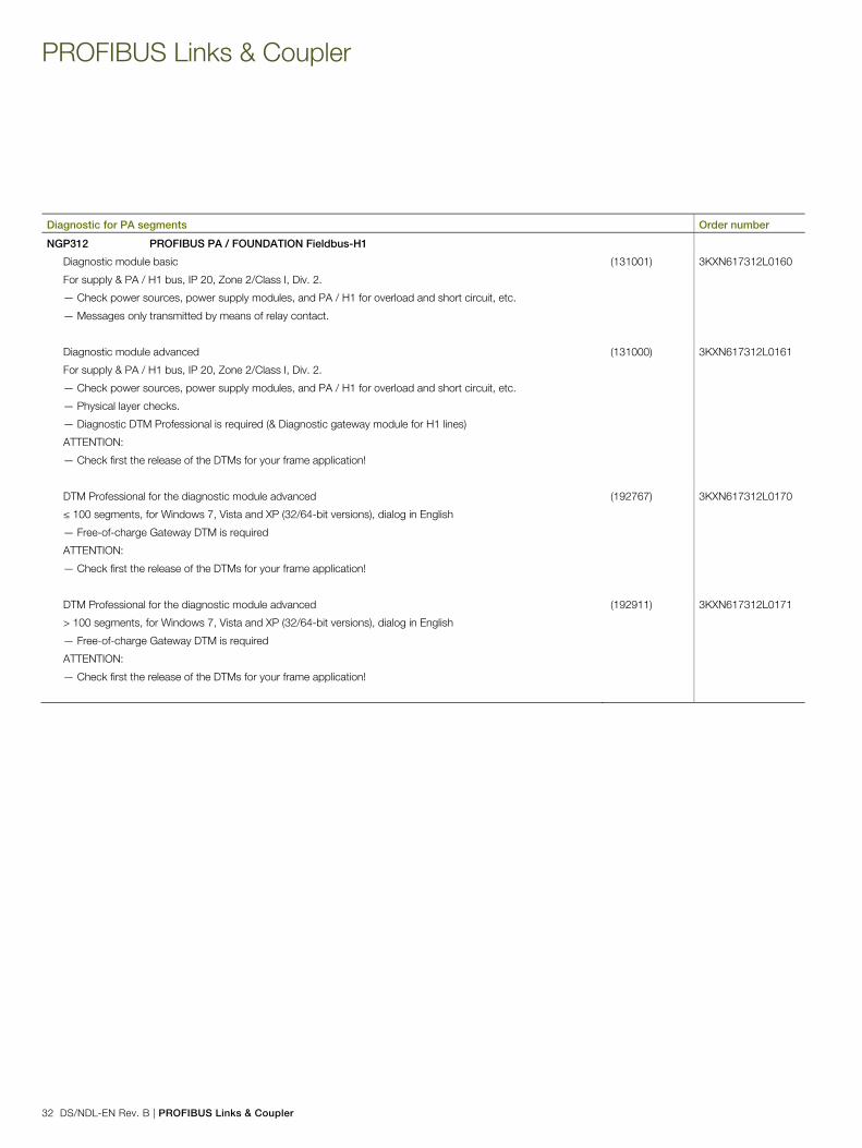
PROFIBUS Links & Coupler
32 DS/NDL-EN Rev. B | PROFIBUS Links & Coupler
Diagnostic for PA segments Order number NGP312 PROFIBUS PA / FOUNDATION Fieldbus-H1
Diagnostic module basic
For supply & PA / H1 bus, IP 20, Zone 2/Class I, Div. 2.
— Check power sources, power supply modules, and PA / H1 for overload and short circuit, etc.
— Messages only transmitted by means of relay contact.
(131001) 3KXN617312L0160
Diagnostic module advanced
For supply & PA / H1 bus, IP 20, Zone 2/Class I, Div. 2.
— Check power sources, power supply modules, and PA / H1 for overload and short circuit, etc.
— Physical layer checks.
— Diagnostic DTM Professional is required (& Diagnostic gateway module for H1 lines)
ATTENTION:
— Check first the release of the DTMs for your frame application!
(131000) 3KXN617312L0161
DTM Professional for the diagnostic module advanced
≤ 100 segments, for Windows 7, Vista and XP (32/64-bit versions), dialog in English
— Free-of-charge Gateway DTM is required
ATTENTION:
— Check first the release of the DTMs for your frame application!
(192767) 3KXN617312L0170
DTM Professional for the diagnostic module advanced
> 100 segments, for Windows 7, Vista and XP (32/64-bit versions), dialog in English
— Free-of-charge Gateway DTM is required
ATTENTION:
— Check first the release of the DTMs for your frame application!
(192911) 3KXN617312L0171
Pos: 37 /Grid-Layout/++++++++++++ Seitenumbruch ++++++++++++ @ 27\mod_1238577222488_0.docx @ 254391 @ @ 1 === Ende der Liste für Textmarke Content ===

Notes
PROFIBUS Links & Coupler | DS/NDL-EN Rev. B 33
Notes

Notes
34 DS/NDL-EN Rev. B | PROFIBUS Links & Coupler
Notes

Notes
PROFIBUS Links & Coupler | DS/NDL-EN Rev. B 35
Notes

Contact us
DS
/ND
L-EN
Rev
. B 0
1.20
17
Pos: 39 /Grid-Layout/Rückseiten Datenblätter/Geräte_Feldbus/Rückseite_NDL @ 79\mod_1417684812879_3101.docx @ 665365 @ @ 1
ABB Automation GmbH Service Instrumentation Kallstadter Straße 1 68309 Mannheim, Germany Customer service center: +49 (0)180 5 222 580* E-Mail: [email protected] www.abb.com/measurement *14 cents/minute from German landlines, max. 42 cents/minute from mobiles.
Note We reserve the right to make technical changes or modify the contents of this document without prior notice. With regard to purchase orders, the agreed particulars shall prevail. ABB does not accept any responsibility whatsoever for potential errors or possible lack of information in this document. We reserve all rights in this document and in the subject matter and illustrations contained therein. Any reproduction, disclosure to third parties or utilization of its contents - in whole or in parts – is forbidden without prior written consent of ABB. Copyright© 2017 ABB All rights reserved 3KXN635000R1001
Sales Service
=== Ende der Liste für Textmarke Backcover ===


